1
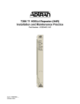
T200 HDSL4 Transceiver Unit, Remote-Local Powered
FRONT PANEL LED STATUS
HDSL4
T200 H4TU-R
DSL1/DSL2
DS1
DSL 1
DSL 2
ALM
ESF/SF
DS1
B8ZS/AMI
ALM
ESF/SF
(YEL) (GRN)
B8ZS/AMI
LLB/RLB
(YEL) (GRN)
LLB/RLB
(YEL) (GRN)
*61223424L2-22B*
Pin
Designation
Description
1
CH GND
Chassis ground
5
DS1-T1
DS1 receive out tip (to customer interface)
7
H1-T
HDSL4 Loop tip (facility)
! Green
! Red
DS1 signal present and no errors currently detected
No DS1 signal, or signal present with errors
11
CH GND
Chassis ground
13
H1-R
HDSL4 Loop ring (facility)
" Off
! Yellow
! Red
No active alarm present
Loss of DSX-1 signal from the network
Loss of DS1 signal from the customer (CPE)
15
DS1-R1
DS1 receive out ring (to customer interface)
17
48 VR
48 VDC Return
20
VCC
+5 VDC for protection switching
" Off
! Green
! Yellow
Unit is provisioned for UNFRAMED data
Unit is provisioned for SF data
Unit is provisioned for ESF data
27
CH GND
Chassis ground
35
48 V
48 VDC; range ±24 to ± 56 VDC (48 VDC nominal)
41
H2-T
HDSL4 Tip (Loop 2)
! Green
! Yellow
Unit is provisioned for AMI line code
Unit is provisioned for B8ZS line code
47
H2-R
HDSL4 Ring (Loop 2)
49
DS1-R
DS1 transmit in ring (from customer interface)
55
DS1-T
DS1 transmit in tip (from customer interface
" Off
! Yellow
! Green
No local loopbacks active
Local loopback active
Active loopback at the H4TU-C toward the customer
R
S
2
3
2
Provisioning options are assumed from settings made at the H4TU-C.
FEATURES
Front Panel Pushbuttons
TScan
REM Initiates a loopback at the H4TU-C toward the customer
The ADTRAN® T200 H4TU-R incorporates the TScan™ feature. TScan allows for remote
retrieval of circuit diagnostics and performs advanced fault location. For more information about
TScan refer to the Installation and Maintenance practice.
DS1 MONITOR JACKS
Bad Splice Detection
LBK
TX
M
O
N
RX
PROVISIONING OPTIONS
OPTIONS
LOC Initiates a bidirectional loopback of the T200 H4TU-R toward the network and customer
LOC
REM
CARD EDGE PINOUTS
Loop 1/Loop 2 synchronization achieved and signal is present
No errors currently detected, and SNR margin ≥ 3 dB
Loop 1/Loop 2 synchronization not achieved, in sync with
errors, or SNR margin < 3 dB
! Red
P/N 1223424L2
CLEI: T1L83Z3C_ _
1223424L2
LOCAL
! Green
61223424L2-22B
0505
TX
RX
DS1 signal from the DCP toward network (nonintrusive)
DS1 receive from the local loop (nonintrusive)
POWER
This specific unit is intended for Local Power Only. If a Span Powered unit is required, refer to
P/N 1223426L2.
A local power supply is available from ADTRAN by ordering P/N 1353.DSK48V04.
The Runtime TScan bad splice detection feature is an ADTRAN proprietary non-intrusive method
for detection of anomalies (bad splices) in the copper plant. This feature non-intrusively monitors
the cable pair during runtime for the presence of bad splices, which may potentially impact service.
Poor splices in the cable are often undetected by normal testing methods. Often, these splices
present no problem for the data transmission equipment until the point at which oxidation with the
splice itself causes a rapid impedance change. Such a change in impedance may cause errors,
signal margin fluctuation, and/or a retrain of the DSL transceivers. The splice detection feature is
accessed from the Troubleshooting Screen via the craft access port.
Fast Retrain
COMPLIANCE
This product is intended to be installed in Restricted Access Areas only and in equipment with
a Type “B” or “E” enclosure.
Code
Input
Output
Power Code
C
C
Telecommunication Code (TC)
X
X
Installation Code (IC)
A
–
Fast Retrain is an ADTRAN proprietary feature that minimizes downtime due to an intermittent
impairment which due to its duration cannot be bridged. When such impairments occur, the fast
retrain feature will be invoked to restore service within 5 to 7 seconds, instead of the traditional 25
to 30 second retrain duration.
NOTE: Fast-Retrain capable units must be installed on both ends of the circuit for this feature
to function properly. Also, if there is a failure, for any reason, of a fast retrain attempt
then the traditional (25-30 second) retrain will be initiated.
This product meets all requirements of Bellcore GR-1089-CORE (Class A2), ANSI T1.4182002. This product is NRTL listed to the applicable UL standards.
C A U T I O N !
WARNING:
Up to –200 VDC may be present on telecommunications wiring. Ensure
Chassis ground is properly connected.
SUBJECT TO ELECTROSTATIC DAMAGE
OR DECREASE IN RELIABILITY.
HANDLING PRECAUTIONS REQUIRED.
For more information, refer to the Installation and Maintenance Practice (P/N 61223HDSL4L2-5) available online at www.adtran.com.
T200 HDSL4 Transceiver Unit, Remote-Local Powered
TROUBLESHOOTING HDSL4
This ADTRAN HDSL4 unit is equipped with troubleshooting-at-a-glance LEDs (identified on the reverse side of
this document) that provide customers with a simple means of identifying the location of certain faults.
Additionally, screens available via the craft interface simplify the trouble isolation process. These screens and their
associated benefits are described below.
PRICING AND AVAILABILITY 800.827.0807
TECH SUPPORT 800.726.8663
RETURN FOR REPAIR 256.963.8722
www.adtran.com
61223424L2-22B
LOOPBACK CONTROL CODES
Pattern
Description
Requires
Arming?
1in3
Loop down all units and disarm.
No
Troubleshooting Screen
2in5
Arming Pattern, H4TU-R will loop up if Smartjack LB is enabled.
No
Available via the Main Menu: provides ADTRAN contact information and access to the Troubleshooting Guidance
and General Information screens.
3in5
Disarm and loop down all units. Restores LB TMO after D5D6.
No
2in6
H4R1 LB to Network.
No
3in6
H4R2 LB to Network.
No
4in6
H4R1 LB to Customer.
No
5in6
H4R2 LB to Customer.
No
3in7
H4TU-R LB to Network.
No
4in7
H4TU-C LB to Network.
No
5in7
H4TU-R LB to Customer.
No
6in7
H4TU-C LB to Customer.
No
3F1E
H4TU-C LB to Customer.
No
3F02
H4TU-R LB to Customer.
No
3F04
H4R1 LB to Customer.
No
3F06
H4R2 LB to Customer.
No
General Information Screen
3F08
H4R3 LB to Customer
No
Available via the Troubleshooting screen: a reference page which displays the minimum acceptable signal margin,
maximum attenuation, and other deployment parameters for this HDSL4 circuit.
NOTE: Along with the Troubleshooting screens, the Detailed Status screen and Performance History screen,
available via the craft access terminal, provide both real-time and historical view of this circuit.
For complete deployment guidelines on the HDSL4 circuit, refer to the Installation and Maintenance
Practice referenced on the front page.
6767
Disable span powering while present.
Yes
9393
Loop down H4TU-C, Repeaters – all loopbacks. Loop down H4TU-R – Cust LB always. Will only
loop down H4TU-R Network LB if NIU is disabled. Does not disarm units if they are armed.
No
C741
H4R1 loopback pattern. 10 bit error injection.
Yes
C742
H4TU-R loopback pattern. 20 bit error injection.
Yes
C754
H4R2 loopback pattern. 200 bit error injection.
Yes
C743
H4R3 loopback pattern. 30 bit error injection.
Yes
D3D3
H4TU-C loop up pattern. 231 bit error injection.
Yes
D5D5
Query Loopback Pattern (error injection) - H4TU-C: 231 Errors, H4R1: 10 Errors,
H4R2: 200 Errors, H4R3: 30 errors, H4TU-R: 20 Errors
No
D5D6
Loopback Timeout Override: Disables LB timeout. Restores original LB timeout when unit is disarmed.
Yes
FF48
FDL Arming Pattern (ESF only). Arms all units, H4TU-R will LB to Network if NIU Enabled (if
pattern sources at network).
No
Recommended Maximum
FF24
FDL Disarm Pattern (ESF only). Loop down and disarm all units
No
10,470 ft.
FF1E
H4TU-C LB to Network. Will not loop up H4TU-C if H4TU-C already in LB to Customer.
No
9,865 ft. 1,2
FF02
H4TU-R LB to Network. Will not loop up H4TU-R if any unit already in LB to Customer.
No
14,770 ft.
FF04
H4R1 LB to Network.
No
14,050 ft. 1,2
FF06
H4R2 LB to Network.
No
FF08
H4R3 LB to Network
No
Troubleshooting Guidance Screens
Available via the Troubleshooting screen: detects and displays errors and/or alarms at any of the monitored inputs
(DSX1, DS1 and HDSL). Guidance on the fault(s) detected includes possible cause(s) and suggested actions,
including those shown below:
DSX-1/DS1:
Facility:
LOS
Loss of signal (Red Alarm) at the DSX-1/DS1
GROUND Ground Fault on span (facility pair grounded)
receiver
SHORT Short circuit (or low impedance) between pairs
CLK
T1 receive clock is out of range
OPEN
Open circuit between facility pairs
RAI
Remote Alarm Indication (Yellow Alarm)
DSL:
detected at DSX-1/DS1 receiver
LOS
Loss of HDSL sync
AIS
Alarm Indication Signal (Blue Alarm) detected
MARG
Margin has exceeded the alarm threshold
at DSX-1/DS1 receiver
ATTEN Attenuation has exceeded the alarm threshold
ERR
Errors recorded at DSX-1/DS1 receiver
ERR
Errors recorded at the HDSL receiver
HIST
Performance History of the DSL units
ATTENUATION LIMITS
Recommended Maximum
Segment
1st
segment
2nd and 3rd segment
Upstream
Downstream
30 dB
32 dB
28 dB
28 dB
RANGE LIMITS, PIC Cable, 70°F
Gauge/Segment
26 Gauge, 1st segment
26 Gauge, 2nd and 3rd segment
24 Gauge, 1st segment
24 Gauge, 2nd and 3rd segment
1
In three segment circuits (two H4Rs), individual segment resistance values must be verified. Refer to the Installation and Maintenance Practice for details and calculations.
2 When designing a dual H4R loop (three segment), the first segment should have lower DC resistance than the
second segment.
Warranty: ADTRAN will replace or repair this product within the warranty period if it does not meet its published specifications or fails while in service.
Warranty information can be found at www.adtran.com/warranty.