1
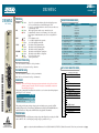
JOBAID
3192 H4TU-C
3192 H4TU-C
CLEI: T1L56YSC_ _
LED STATUS
DSL1/DSL2
DEFAULT PROVISIONING VALUES
● Green
● Red
DSX
● Green
● Red
ALM
●
●
●
●
●
●
●
●
●
●
H TUC
1222404L1
DSL 1
ESF/SF
DSL 2
B8ZS/AMI
LBK
Off
Red
Yellow
Off
Yellow
Green
Yellow
Green
Off
Yellow
Loop 1/ Loop 2 synchronization achieved and signal is present.
No errors currently detected, and SNR margin ≥ 3 dB.
Loop 1/ Loop 2 synchronization not achieved, in sync with errors,
or SNR margin < 3 dB.
DSX-1 signal present and no errors currently detected.
In framed mode, denotes loss of framing or loss of sync at the
DSX-1 input. In unframed mode, denotes loss of signal DSX-1
input.
No T1 alarms are active.
Loss of DSX-1 signal from the network.
Loss of DS1 signal from the CPE.
Unit has detected Unframed data.
Unit has detected ESF framing data.
Unit has detected SF framing data.
Unit has detected B8ZS line coding data.
Unit has detected AMI line coding data.
No local loopbacks active.
Local loopback active.
DSX EQ SPLITTING JACKS
DSX
/DS1
TX
DSX EQ
TX
Provisioning Options
Option Settings
0-133 Feet
2.
3.
4.
5.
6.
7.
8.
9.
10.
11.
12.
B8ZS
ESF
Disabled
Enabled
120 Minutes
T1 (Disabled)
–7.5 dB
Enabled
AIS/CI
Auto
34 dB
13.
14.
0-133 Feet
133-266 Feet
266- 399 Feet
399-533 Feet
533-655 Feet
DSX-1/DS1 Line Code
AMI, B8ZS
DSX-1/DS1 Framing
SF, ESF, Unframed, Auto
Forced Frame Conversion
Enabled, Disabled
Smartjack Loopback
Enabled, Disabled
Loopback Timeout
None, 120 Minutes
Latching Loopback Mode
T1 (Disabled), FT1 (Enabled)
DS1 TX Level
0 dB, –7.5 dB, –15 dB
Span Power
Enabled, Disabled
Customer Loss Indicator
AIS, AIS/CI, Loopback
PRM Setting
None, SPRM, NPRM, Auto
Loop Atten Alarm Threshold 0 (Disabled)
1-99 dB
SNR Margin Alarm Threshold 0 (Disabled)
1-15 dB
Remote Provisioning
Enabled, Disabled
RX
B8ZS
/AMI
TX
DSX-1 transmit toward the local loop (nonintrusive)
RX DSX-1 receive from the local loop (nonintrusive)
LBK
TX
RX
DSX MON
COMPLIANCE
WARNING: Up to –200 VDC might be present on telecommunications wiring. Ensure chassis
ground is properly connected. The DSX-1 interface is intended for connection to
intra-building wiring only.
This product is intended for installation in restricted access locations only and in equipment
with a Type “B” or “E” enclosure.
ut
R
S
2
3
2
Code
Input Output
Power Code (PC)
F
C
Telecommunication Code (TC) –
X
Installation Code (IC)
A
–
This product provides span powering voltage (negative only with respect to ground, –190 VDC
nominal, GFI protection < 5 mA) and meets all requirements of Bellcore GR-1089-CORE (Class A2),
and ANSI T1.418-2002. This product is NRTL Listed to the applicable UL standards.
POWERING MODE
H4TU-C EDGE CONNECTOR WIRING
1
2
3
4
5
6
7
8
9
10
A
B
C
D
E
F
H
J
K
L
R Tx DSX (In from DSX)
R1 Rx DSX (Out to DSX)
GND
R1 HDSL4 Loop 2
—48V
R HDSL4 Loop 1
Fuse Alarm (to Alarm Module)
T Tx DSX (In from DSX)
T1 Rx DSX (Out to DSX)
T1 HDSL4 Loop 2
RCV LOS (to Alarm Module)
Frame Ground
T HDSL4 Loop 1
The H4TU-C provides –190 VDC span powering voltage and will provide powering to the H4Rs
and the H4TU-R. The –190 VDC span powering voltage is provided on Loop 2.
C A U T I O N !
SUBJECT TO ELECTROSTATIC DAMAGE
OR DECREASE IN RELIABILITY.
HANDLING PRECAUTIONS REQUIRED.
Default Settings
1. DSX-1 Line Build Out
DSX MONITOR JACKS
ESF
/SF
#61222404L1-22D#
DSX-1 transmit toward the local loop (intrusive)
RX DSX-1 receive from the local loop (intrusive)
ALM
61222404L1-22D
0311
■ For a complete Installation and Maintenance Practice (P/N 61222404L1-5): 877-457-5007, Faxback Document 885. Please have your fax number ready. ■
4 dB
Enabled
HDSL4 TROUBLESHOOTING GUIDE
ADTRAN HDSL4 equipment is designed with troubleshooting-at-a-glance features. The following information provides
suggestions for troubleshooting as a result of LED indications which are indicative of loop trouble.
NOTE: Pressing “ESC” while on any screen will go back to the previous screen.
INDICATIONS AND POSSIBLE CAUSES
DSL LED Red
Connect a terminal or PC to the RS-232 (DB-9) craft interface on the front panel. The terminal must be VT100 or compatible
and set for 1.2 to 19.2 kbps, 8 data bits, no parity, 1 stop bit, no flow control. Select “3” from the ADTRAN HDSL4 Main Menu
screen and “1” from the Span Status Screen. Verify the following conditions on the HDSL4 and T1 Detailed Status Screen:
■ Margin ≥ 3 dB
■ Attenuation ≤ 35 dB (1st segment)
Attenuation ≤ 31 dB (2nd segment)
■ No ES, SES, or UAS (Performance History Screen, Main
Menu Selection 5)
If the above conditions do exist, the circuit should provide
quality service; however, if any of the above conditions do not
exist, a cable problem or excessive loss situation is probable,
and more detailed cable testing should be done to verify all
HDSL4 loop specifications are met. These conditions may also
reflect intermittent cable faults or excessive noise impairments.
If intermittent faults or noise impairments are suspected, review
the Performance History Screen.
HDSL4 DEPLOYMENT GUIDELINES
The guidelines provided below apply to the segments of an
HDSL4 circuit, as follows:
1st segment = between the H4TU-C and H4R
NOTE: The insertion loss reading shown on the Detailed Status
Screen is an approximation that is valid for some loops.
Exercise caution when using this value.
2nd segment = between two H4Rs or single H4R and H4TU-R
3rd segment = between the second H4R and the H4TU-R
These deployment guidelines provide the basics for HDSL4 circuit provisioning. If these parameters are met, then the circuit
will provide quality service. If not, a cable problem or excessive loss situation is probable. In this case, a more detailed cable
analysis is required to ensure that all HDSL4 loop specifications are met. These conditions may also be the result of
intermittent cable faults or intermittent noise impairments. If intermittent problems are suspected, utilize the Performance
History screen to assist in troubleshooting.
Range Limits: 26 Gauge / 70ºF / PIC
1. All loops are nonloaded only
Recommended Maximum
2. Any single bridged tap is limited to 2 kft.
(DSL Assistant Green Zone)
3. Total bridged tap length is limited to 2.5 kft.
1st segment
10.8 kft.
4. Bridge tap within 1000 feet of units may affect performance of the
2nd/3rd segment
10.55 kft.
circuit
Range Limits: 24 Gauge / 70ºF / PIC
5. Margin ≥ 6 dB (Detailed Status Screen)
Recommended Maximum
6. No ES, SES, or UAS (Performance History Screen)
(DSL Assistant Green Zone)
7. Foreign Voltage DC (t-r, t-g, r-g) < 3 VDC
1st segment
15.25 kft.
8. Insulation Resistance (t-r, r-g, t-g) > 3.5 MΩ
2nd/3rd segment
15.05 kft.
9. Impulse Noise ≤ –40 dBmF (measured with an F filter)
10. Wideband Noise ≤ –54 dBmF
Attenuation Limits
11. Longitudinal Noise (Power Influence) < 80 dBrnC OK
Recommended Maximum
80–90 dBrnc Marginal
(DSL Assistant Green Zone)
> 90 dBrnc
Unacceptable
1st segment
2nd/3rd segment
Upstream
31 dB
30 dB
Downstream
33 dB
30 dB
NOTE: In three segment circuits (two H4Rs), individual
segment resistance values must be verified. Refer
to the HDSL4 Deployment Guidelines section of
the Installation and Maintenance Practice
(P/N 61222404L1-5x) for those guidelines.
PRICING AND AVAILABILITY 800.827.0807
TECHNICAL SUPPORT 800.726.8663
RETURN FOR REPAIR 256.963.8722
www.adtran.com
61222404L1-22D
LOOPBACK AND CONTROL CODES
Pattern
1in3
2in5
3in5
1in6
2in6
3in6
4in6
5in6
3in7
4in7
5in7
6in7
3F1E
3F02
3F04
3F06
6767
9393
C741
C742
C754
D3D3
D5D5
D5D6
FF48
FF24
FF1E
FF02
FF04
FF06
Description
Requires Arming?
Loop down all units and disarm.
No
Arming Pattern, H4TU-R will loop up if Smartjack LB is enabled.
No
Disarm and loop down all units. Restores LB TMO after D5D6.
No
Network Arming Pattern. If Smartjack LB is enabled, HTU-R will loop toward network.
No
H4R LB to Network.
No
H4R LB to Network.
No
H4R LB to Customer.
No
H4R LB to Customer.
No
H4TU-R LB to Network.
No
H4TU-C LB to Network.
No
H4TU-R LB to Customer.
No
H4TU-C LB to Customer.
No
H4TU-C LB to Customer.
No
H4TU-R LB to Customer.
No
H4R LB to Customer.
No
H4R LB to Customer.
No
Disable span powering while present.
Yes
Loop down H4TU-C, Repeaters - all loopbacks. Loop down H4TU-R - Cust LB always.
Will only loop down H4TU-R Network LB if NIU is disabled. Does not disarm units if they
are armed.
No
H4R #1 loop up pattern. 10 bit error injection.
Yes
H4TU-R loop up pattern. 20 bit error injection.
Yes
H4R #2 loop up pattern. 200 bit error injection.
Yes
H4TU-C loop up pattern. 231 bit error injection.
Yes
Query Loopback Pattern (error injection)
H4TU-C: 231 Errors, H4R #1: 10 Errors, H4R #2: 200 Errors, H4TU-R: 20 Errors
No
Loopback Timeout Override: Disables LB timeout. Restores original LB timeout when unit
is disarmed.
Yes
FDL Arming Pattern (ESF only). Arms all units, H4TU-R will LB to Network if NIU Enabled
(if pattern sources at network).
No
FDL Disarm Pattern (ESF only). Loop down and disarm all units
No
H4TU-C LB to Network. Will not loop up H4TU-C if H4TU-C already in LB to Customer.
No
H4TU-R LB to Network. Will not loop up H4TU-R if any unit already in LB to Customer.
No
H4R LB to Network.
No
H4R LB to Network.
No
WARRANTY
ADTRAN will replace or repair this product within the warranty period if it does not meet its published
specifications or fails while in service. Warranty information can be found at
www.adtran.com/warranty. U.S. and Canada customer Faxback: 877-457-5007, Document 414.