1
BD9:AL&,&*
)M+BZiVa8jii^c\
7VcYhVl
DLC:GHB6CJ6A
;DGBD9:AHB6CJ;68IJG:96;I:G'$%-
E]dcZ/&"(+%",()"()-'Dc"A^cZIZX]c^XVaHjeedgi/iZX]"hjeedgi5lddYhidX`^ci#Xdb
8DENG><=I?jan!'%%(7NLDD9HID8@>CI:GC6I>DC6A!>C8#G:K>H:9B6N!'%%.IH
L6GC>C</CDEDGI>DCD;I=>HB6CJ6AB6N7:G:EGD9J8:9>C6CNH=6E:DG;DGBL>I=DJI
I=:LG>II:C6EEGDK6AD;LDD9HID8@>CI:GC6I>DC6A!>C8#
*)(*?I
Eg^ciZY^c8]^cV
K_`jdXelXcgifm`[\jZi`k`ZXcjX]\kp`ejkilZk`fejfek_\gifg\ij\klg#
fg\iXk`fe#dX`ek\eXeZ\Xe[j\im`Z\f]k_`jdXZ_`e\&\hl`gd\ek%
=X`cli\kfi\X[#le[\ijkXe[Xe[]fccfnk_\`ejkilZk`fej^`m\e`ek_`j
dXelXcdXpi\jlck`ej\i`fljg\ijfeXc`ealip#`eZcl[`e^XdglkXk`fe#
\c\ZkifZlk`fefi[\Xk_%
K_\fne\if]k_`jdXZ_`e\&\hl`gd\ek`jjfc\cpi\jgfej`Yc\]fi`kjjX]\
lj\%K_`ji\jgfej`Y`c`kp`eZcl[\jYlk`jefkc`d`k\[kfgifg\i`ejkXccX$
k`fe`eXjX]\\em`ifed\ek#g\ijfee\ckiX`e`e^Xe[ljX^\Xlk_fi`qX$
k`fe#gifg\i`ejg\Zk`feXe[dX`ek\eXeZ\#dXelXcXmX`cXY`c`kpXe[
Zfdgi\_\ej`fe#Xggc`ZXk`fef]jX]\kp[\m`Z\j#YcX[\&Zlkk\i`ek\^i`kp#
Xe[k_\ljX^\f]g\ijfeXcgifk\Zk`m\\hl`gd\ek%
K_\dXel]XZkli\in`ccefkY\_\c[c`XYc\]fi`ealipfigifg\ikp
[XdX^\]ifde\^c`^\eZ\#`dgifg\ikiX`e`e^#dXZ_`e\df[`]`ZXk`fejfi
d`jlj\%
Jfd\[ljkZi\Xk\[Ypgfn\ijXe[`e^#jXn`e^#^i`e[`e^#[i`cc`e^#Xe[
fk_\iZfejkilZk`feXZk`m`k`\jZfekX`ejZ_\d`ZXcjbefnekfk_\JkXk\f]
:Xc`]fie`XkfZXlj\ZXeZ\i#Y`ik_[\]\Zkjfifk_\ii\gif[lZk`m\_Xid%
Jfd\\oXdgc\jf]k_\j\Z_\d`ZXcjXi\1
C\X[]ifdc\X[$YXj\[gX`ekj%
:ipjkXcc`e\j`c`ZX]ifdYi`Zbj#Z\d\ekXe[fk_\idXjfeipgif[lZkj%
8ij\e`ZXe[Z_ifd`ld]ifdZ_\d`ZXccp$ki\Xk\[cldY\i%
Pflii`jb]ifdk_\j\\ogfjli\jmXi`\j#[\g\e[`e^fe_fnf]k\epfl
[fk_`jkpg\f]nfib%Kfi\[lZ\pfli\ogfjli\kfk_\j\Z_\d`ZXcj1
Nfib`eXn\ccm\ek`cXk\[Xi\X#Xe[nfibn`k_Xggifm\[jX]\kp\hl`g$
d\ek#jlZ_Xjk_fj\[ljkdXjbjk_XkXi\jg\Z`Xccp[\j`^e\[kf]`ck\i
flkd`ZifjZfg`ZgXik`Zc\j%
@EKIF;L:K@FE%%%%%%%%%%%%%%%%%%%%%%%%%%%%%%%%%%%%%)
Woodstock Technical Support .................. 2
8::<JJFI@<J%%%%%%%%%%%%%%%%%%%%%%%%%%%%%%%%%%%%%% )/
Metal Cutting Bandsaw Accessories ......... 28
<C<:KI@:8C%%%%%%%%%%%%%%%%%%%%%%%%%%%%%%%%%%%%%%% ('
110V Operation ................................. 10
Extension Cords ................................ 10
Electrical Specifications ...................... 10
D8@EK<E8E:<%%%%%%%%%%%%%%%%%%%%%%%%%%%%%%%%%%%% )0
General .......................................... 29
Cleaning ......................................... 29
Lubrication ...................................... 29
J8=<KP
J<KLG%%%%%%%%%%%%%%%%%%%%%%%%%%%%%%%%%%%%%%%%%%%%%% ((
Unpacking ....................................... 11
Inventory ........................................ 11
Machine Placement ............................ 12
Cleaning Machine............................... 12
Test Run.......................................... 17
J<IM@:<%%%%%%%%%%%%%%%%%%%%%%%%%%%%%%%%%%%%%%%%%%%% *'
Blade Change ................................... 30
Blade Tracking .................................. 31
Blade Tension ................................... 32
Squaring Blade .................................. 32
Blade Guide Bearings .......................... 33
Electrical Safety Instructions................. 35
Electrical Components ........................ 36
Wiring Diagram ................................. 36
Troubleshooting................................. 37
<C<:KI@:8C
@EKIF;L:K@FE
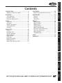
:fek\ekj
G8IKJ%%%%%%%%%%%%%%%%%%%%%%%%%%%%%%%%%%%%%%%%%%%%%% *0
N8II8EKP%%%%%%%%%%%%%%%%%%%%%%%%%%%%%%%%%%%%%%%% +,
J<KLG
FG<I8K@FEJ%%%%%%%%%%%%%%%%%%%%%%%%%%%%%%%%%%%%%%% (/
General .......................................... 18
Operation Tips .................................. 19
Vertical Operation ............................. 20
Head Locking Pin ............................... 21
Blade Guides .................................... 23
Feed Rate ....................................... 23
Blade Terminology ............................. 25
Blade Selection ................................. 26
Metal Chip Inspection Chart .................. 27
FG<I8K@FEJ
D8@EK<E8E:<
J<IM@:<
G8IKJ
LJ<K?<HL@:B>L@;<G8><C89<CJKFJ<8I:?FLK@E=FID8K@FE=8JK
@EKIF;L:K@FE
N(.(,Fne\ijDXelXcD]^%J`eZ\)&'/
@EKIF;L:K@FE
Nff[jkfZbK\Z_e`ZXcJlggfik
This machine has been specially designed to provide many years of trouble-free service. Close attention
to detail, ruggedly built parts and a rigid quality control program assure safe and reliable operation.
Woodstock International, Inc. is committed to customer satisfaction. Our intent with this manual is to
include the basic information for safety, setup, operation, maintenance, and service of this product.
We stand behind our machines! In the event that questions arise about your machine, please
contact Woodstock International Technical Support at (360) 734-3482 or send e-mail to:
k\Z_$jlggfik7j_fg]fo%Y`q. Our knowledgeable staff will help you troubleshoot problems and process
warranty claims.
If you need the latest edition of this manual, you can download it from _kkg1&&nnn%j_fg]fo%Y`q.
If you have comments about this manual, please contact us at:
Nff[jkfZb@ek\ieXk`feXc#@eZ%
8kke1K\Z_e`ZXc;fZld\ekXk`feDXeX^\i
G%F%9fo)*'0
9\cc`e^_Xd#N80/)).
<dX`c1dXelXcj7nff[jkfZb`ek%Zfd
-2-
B68=>C:
HE:8>;>86I>DCH
Phone #: (360) 734-3482 • Online Tech Support: [email protected] • Web: www.shopfox.biz
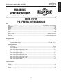
BD9:AL&,&*
)M+B:I6A8JII>C<76C9H6L
Dfkfi
Type .......................................................................................... TEFC Capacitor Start Induction
Horsepower ............................................................................................................... 3⁄4 HP
Voltage ...................................................................................................................... 110V
Phase....................................................................................................................... Single
Amps ............................................................................................................................ 5A
Speed .................................................................................................................. 1725 RPM
Cycle ........................................................................................................................ 60 Hz
Number Of Speeds ............................................................................................................. 1
Power Transfer ...........................................................................................V-Belt & Gear Drive
Bearings ............................................................................................... Sealed and Lubricated
DX`eJg\Z`]`ZXk`fej
Fg\iXk`fe@e]fidXk`fe
Blade Speeds ..........................................................................................78, 108, 180 FPM
Standard Blade Length .......................................................................... 1⁄2" x 0.028" x 64 1⁄2"
:lkk`e^:XgXZ`k`\j
Angle Cuts ..........................................................................................................0°–60°
Vise Jaw Depth ...................................................................................................... 6 1⁄2"
Vise Jaw Height ..................................................................................................... 3 1⁄4"
Max. Capacity Rectangle Height at 90° ......................................................................... 4 1⁄2"
Max. Capacity Rectangle Width at 90° ............................................................................. 6"
Max. Capacity Round at 90° ....................................................................................... 4 1⁄2"
Max. Capacity Rectangle Height at 45° ......................................................................... 4 1⁄2"
Max. Capacity Rectangle Width at 45° .......................................................................... 3 1⁄2"
Max. Capacity Round at 45° ....................................................................................... 3 1⁄2"
Max. Capacity Rectangle Height at 60° ......................................................................... 4 1⁄2"
Max. Capacity Rectangle Width at 60° ............................................................................. 5"
Max. Capacity Round at 60° ....................................................................................... 4 1⁄2"
Fm\iXcc;`d\ej`fej
Weight .................................................................................................................. 144 lbs.
Length ......................................................................................................................... 16"
Width .......................................................................................................................... 39"
Height ......................................................................................................................... 19"
Foot Print (Length/Width).....................................................................................13 3⁄4" x 19 3⁄4"
-3-
@EKIF;L:K@FE
N(.(,Fne\ijDXelXcD]^%J`eZ\)&'/
@EKIF;L:K@FE
N(.(,Fne\ijDXelXcD]^%J`eZ\)&'/
:fejkilZk`feDXk\i`Xcj
Table .................................................................................................................... Cast Iron
Stand ......................................................................................................... Pre-Formed Steel
Body............................................................................................................. Aluminum Cast
Wheel ................................................................................................................... Cast Iron
Base ..................................................................................................................... Cast Iron
Paint ...................................................................................................Urethane Hammertone
J_`gg`e^;`d\ej`fej
Weight ................................................................................................................... 148 lbs.
Length ...................................................................................................................... 17 3⁄4"
Width ....................................................................................................................... 21 1⁄2"
Height ......................................................................................................................... 37"
<c\Zki`ZXc
Switch ..................................................................................................... Automatic Shut-Off
Switch Voltage ............................................................................................................. 110V
Cord Length.............................................................................................................. 6 1⁄2 ft.
Cord Gauge ............................................................................................................ 18 gauge
Recommended Breaker Size...........................................................................................15 amp
Plug ............................................................................................................................ Yes
Fk_\i
Wheel Size .................................................................................................................. 7 3⁄8"
Blade Guides Upper .............................................................................................. Ball Bearing
Blade Guides Lower .............................................................................................. Ball Bearing
Table Information
Length ...................................................................................................................... 10 1⁄4"
Width ........................................................................................................................ 6 3⁄4"
Thickness .................................................................................................................... 1 1⁄4"
Floor to Table Height........................................................................................................ 33"
=\Xkli\j
Horizontal & Vertical Operation
Automatic Shut-Off
3
⁄4 HP Motor
Work Stop
-4-
@EKIF;L:K@FE
N(.(,Fne\ijDXelXcD]^%J`eZ\)&'/
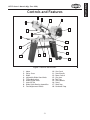
:fekifcjXe[=\Xkli\j
5
4
2
3
6
1
7
8
9
18
10
17
12
11
16
13
15
14
=`^li\(% Machine Identification.
(.
).
*.
+%
,%
-%
.%
/%
0.
Motor
Pulley Cover
Blade
Adjustable Blade Guard Knob
Tilting Mechanism
Blade Tension Knob
Auto Off Tab
Blade Guide Bearing Assemblies
Feed Adjustment Handle
-5-
('% Vise Crank
((% Stand Handle
()% Power Switch
(*% Vise Jaws
(+% Tool Tray
(,% Stand Wheels
(-% Stand
(.% Work Stop
(/% Horizontal Stop
N(.(,Fne\ijDXelXcD]^%J`eZ\)&'/
J8=<KP
J8=<KP
I<8;D8EL8C9<=FI<FG<I8K@E>D8:?@E<%
=8@CLI<KF=FCCFN@EJKIL:K@FEJ9<CFNN@CC
I<JLCK@EG<IJFE8C@EALIP%
@e[`ZXk\jXe`dd`e\ekcp_XqXi[fljj`klXk`fen_`Z_#`]efkXmf`[\[#N@CC
i\jlck`e[\Xk_fij\i`flj`ealip%
@e[`ZXk\jXgfk\ek`Xccp_XqXi[fljj`klXk`fen_`Z_#`]efkXmf`[\[#:FLC;
i\jlck`e[\Xk_fij\i`flj`ealip%
@e[`ZXk\jXgfk\ek`Xccp_XqXi[fljj`klXk`fen_`Z_#`]efkXmf`[\[#D8P
i\jlck`ed`efifidf[\iXk\`ealip%
EFK@:<
K_`jjpdYfc`jlj\[kfXc\ikk_\lj\ikflj\]lc`e]fidXk`feXYflkgifg\i
fg\iXk`fef]k_\\hl`gd\ek#Xe[&fiXj`klXk`fek_XkdXpZXlj\[XdX^\
kfk_\dXZ_`e\ip%
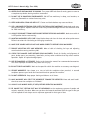
JkXe[Xi[JX]\kp@ejkilZk`fej
(% I<8;K?IFL>?K?<<EK@I<D8EL8C9<=FI<JK8IK@E>D8:?@E<IP%DXZ_`e\ipgi\j\ekjj\i`flj
`ealip_XqXi[jkflekiX`e\[lj\ij%
)% 8CN8PJ LJ< 8EJ@ 8GGIFM<; J8=<KP >C8JJ<J N?<E FG<I8K@E> D8:?@E<IP% <m\ip[Xp \p\$
^cXjj\jfecp_Xm\`dgXZki\j`jkXekc\ej\jÇk_\pXi\EFKjX]\kp^cXjj\j%
*% 8CN8PJN<8I8E@FJ?8GGIFM<;I<JG@I8KFIN?<EFG<I8K@E>D8:?@E<IPK?8KGIF;L:<J
;LJK%Nff[[ljk`jXZXiZ`ef^\eXe[ZXeZXlj\ZXeZ\iXe[j\m\i\i\jg`iXkfip`cce\jj\j%
+% 8CN8PJ LJ< ?<8I@E> GIFK<:K@FE N?<E FG<I8K@E> D8:?@E<IP% DXZ_`e\ip ef`j\ ZXe ZXlj\
g\idXe\ek_\Xi`e^[XdX^\%
,% N<8IGIFG<I8GG8I<C%;FEFKn\Xicffj\Zcfk_`e^#^cfm\j#e\Zbk`\j#i`e^j#fia\n\cipn_`Z_dXp
^\k ZXl^_k `e dfm`e^ gXikj% N\Xi gifk\Zk`m\ _X`i Zfm\i`e^ kf ZfekX`e cfe^ _X`i Xe[ n\Xi efe$jc`g
]ffkn\Xi%
-% E<M<IFG<I8K<D8:?@E<IPN?<EK@I<;#FILE;<IK?<@E=CL<E:<F=;IL>JFI8C:F?FC%
9\d\ekXccpXc\ikXkXcck`d\jn_\eilee`e^dXZ_`e\ip%
.% FECP8CCFNKI8@E<;8E;GIFG<ICPJLG<IM@J<;G<IJFEE<CKFFG<I8K<D8:?@E<IP%DXb\
jli\fg\iXk`fe`ejkilZk`fejXi\jX]\Xe[Zc\Xicple[\ijkff[%
/% B<<G:?@C;I<E8E;M@J@KFIJ8N8P%B\\gXccZ_`c[i\eXe[m`j`kfijXjX]\[`jkXeZ\]ifdk_\nfib
Xi\X%
0% D8B<NFIBJ?FG:?@C;GIFF=%Lj\gX[cfZbj#dXjk\ijn`kZ_\j#Xe[i\dfm\jkXikjn`kZ_b\pj%
-6-
N(.(,Fne\ijDXelXcD]^%J`eZ\)&'/
('% E<M<IC<8M<N?<ED8:?@E<@JILEE@E>%Kliegfn\iF==Xe[XccfnXccdfm`e^gXikjkfZfd\kf
XZfdgc\k\jkfgY\]fi\c\Xm`e^dXZ_`e\leXkk\e[\[%
((% ;FEFKLJ<@E;8E><IFLJ<EM@IFED<EKJ%;FEFKlj\dXZ_`e\ip`e[Xdg#n\kcfZXk`fej#fi
n_\i\Xep]cXddXYc\fiefo`flj]ld\jdXp\o`jk%
(*% LJ<8>IFLE;<;<OK<EJ@FE:FI;I8K<;=FIK?<D8:?@E<8DG<I8><%Le[\ij`q\[Zfi[jfm\i$
_\XkXe[cfj\gfn\i%I\gcXZ\\ok\ej`feZfi[j`]k_\pY\Zfd\[XdX^\[%;FEFKlj\\ok\ej`feZfi[j
]fi))'MdXZ_`e\ip%
(+% 8CN8PJ;@J:FEE<:K=IFDGFN<IJFLI:<9<=FI<J<IM@:@E>D8:?@E<IP%DXb\jli\jn`kZ_`j
`eF==gfj`k`feY\]fi\i\Zfee\Zk`e^%
(,% D8@EK8@ED8:?@E<IPN@K?:8I<%B\\gYcX[\jj_XigXe[Zc\Xe]fiY\jkXe[jX]\jkg\i]fidXeZ\%
=fccfn`ejkilZk`fej]ficlYi`ZXk`e^Xe[Z_Xe^`e^XZZ\jjfi`\j%
(-% D8B<JLI<>L8I;J8I<@EGC8:<8E;NFIB:FII<:KCP9<=FI<LJ@E>D8:?@E<IP%
(.% I<DFM< 8;ALJK@E> B<PJ 8E; NI<E:?<J% DXb\ X _XY`k f] Z_\Zb`e^ ]fi b\pj Xe[ X[aljk`e^
ni\eZ_\jY\]fi\klie`e^dXZ_`e\ipFE%
(/% :?<:B =FI ;8D8><; G8IKJ 9<=FI< LJ@E> D8:?@E<IP% :_\Zb ]fi Y`e[`e^ Xe[ Xc`^ed\ek f]
gXikj#Yifb\egXikj#gXikdflek`e^#cffj\Yfckj#Xe[Xepfk_\iZfe[`k`fejk_XkdXpX]]\ZkdXZ_`e\
fg\iXk`fe%I\gX`ifii\gcXZ\[XdX^\[gXikj%
(0% LJ<I<:FDD<E;<;8::<JJFI@<J%I\]\ikfk_\`ejkilZk`fedXelXc]fii\Zfdd\e[\[XZZ\jjfi`\j%
K_\lj\f]`dgifg\iXZZ\jjfi`\jdXpZXlj\i`jbf]`ealip%
)'%;FEFK=FI:<D8:?@E<IP%NfibXkk_\jg\\[]fin_`Z_k_\dXZ_`e\fiXZZ\jjfipnXj[\j`^e\[%
)(% J<:LI< NFIBG@<:<% Lj\ ZcXdgj fi X m`j\ kf _fc[ k_\ nfibg`\Z\ n_\e giXZk`ZXc% 8 j\Zli\[
nfibg`\Z\gifk\Zkjpfli_Xe[jXe[]i\\jYfk__Xe[jkffg\iXk\k_\dXZ_`e\%
))% ;FEFKFM<II<8:?%B\\ggifg\i]ffk`e^Xe[YXcXeZ\XkXcck`d\j%
)*% D8EPD8:?@E<JN@CC<A<:KK?<NFIBG@<:<KFN8I;K?<FG<I8KFI%BefnXe[Xmf`[Zfe[`$
k`fejk_XkZXlj\k_\nfibg`\Z\kfb`ZbYXZb%
)+% 8CN8PJCF:BDF9@C<98J<J@=LJ<; 9<=FI<FG<I8K@E>D8:?@E<IP%
),% 9< 8N8I< K?8K :<IK8@E ;LJK D8P 9< ?8Q8I;FLJ kf k_\ i\jg`iXkfip jpjk\dj f] g\fgc\ Xe[
Xe`dXcj#\jg\Z`Xccp]`e\[ljk%DXb\jli\pflbefnk_\_XqXi[jXjjfZ`Xk\[n`k_k_\kpg\f][ljkpfl
n`ccY\\ogfj\[kfXe[XcnXpjn\XiXi\jg`iXkfiXggifm\[]fik_Xkkpg\f][ljk%
-7-
J8=<KP
()% B<<GNFIB8I<8:C<8E8E;N<CCC@K%:clkk\iXe[[Xibj_X[fnjdXpZXlj\XZZ`[\ekj%
N(.(,Fne\ijDXelXcD]^%J`eZ\)&'/
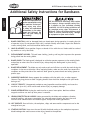
J8=<KP
8[[`k`feXcJX]\kp@ejkilZk`fej]fi9Xe[jXnj
I<8;Xe[le[\ijkXe[k_`j
\ek`i\dXelXcY\]fi\lj`e^
k_`jdXZ_`e\%J\i`fljg\i$
jfeXc `ealip dXp fZZli
`] jX]\kp Xe[ fg\iXk`feXc
`e]fidXk`fe `j efk le[\i$
jkff[ Xe[ ]fccfn\[% ;F
EFK i`jb pfli jX]\kp Yp
efki\X[`e^
LJ<k_`jXe[fk_\idXZ_`e\ipn`k_ZXlk`fe
Xe[ i\jg\Zk% 8cnXpj Zfej`[\i jX]\kp ]`ijk#
Xj `k Xggc`\j kf pfli `e[`m`[lXc nfib`e^
Zfe[`k`fej%Efc`jkf]jX]\kp^l`[\c`e\jZXe
Y\ Zfdgc\k\Ç\m\ip j_fg \em`ifed\ek `j
[`]]\i\ek%=X`cli\kf]fccfn^l`[\c`e\jZflc[
i\jlck `e j\i`flj g\ijfeXc `ealip# [XdX^\
kf\hl`gd\ekfigffinfibi\jlckj%
(% 9C8;<:FE;@K@FE% A dull or damaged blade can break apart during operation, increasing the risk
of operator injury. Do not operate with a dull, cracked or badly worn blade. Inspect the blade for
cracks, missing teeth, and weld condition before each use.
)% ?8E;GC8:<D<EK% Never position fingers or thumbs in line with the cut. Hands could be crushed
by machine or cut by the blade.
*% <EK8E>C<D<EK?8Q8I;J% Tie back loose clothing, jewelry, and long hair to prevent the operator
being pulled into the moving blade.
+% 9C8;<>L8I;%The blade guard is designed to minimize operator exposure to the rotating blade
and pulleys to reduce the risk of serious injury. Always keep the blade guard in place during
operation.
+% 9C8;<I<GC8:<D<EK% The blade can only make a safe and efficient cut with the teeth facing the
workpiece in the correct direction. When replacing blades, make sure the teeth face toward the
workpiece and the pivot side of the machine. Wear gloves to protect hands and safety glasses to
protect eyes.
,% NFIBG@<:<?8E;C@E>% Always support the workpiece with the table, vise, or other support
fixtures. Flag long pieces to avoid a tripping hazard. Never hold the workpiece with your hands
during a cut.
-% CFJJF=JK89@C@KP% Unsupported workpieces may jeopardize machine stability and cause the
machine to tip or fall, which could cause serious injury or property damage.
.% GFN<I@EK<IILGK@FE% Unplug the machine after a power interruption. Machines without
magnetic switches can start up after power is restored.
0% ?<8I@E>GIFK<:K@FE?8Q8I;J% Noise generated by the blade and workpiece vibration,
material handling, and power transmission can cause permanent hearing loss over time and
interfere with communication and audible signals. Always wear hearing protection.
('% ?FKJLI=8:<J% Due to friction, the workpiece, chips, and some machine components can be hot
enough to burn you.
((% JK8IK@E>GFJ@K@FE% Never turn the saw ON with the blade resting on the workpiece to prevent
blade breakage that could cause a serious injury hazard to the operator.
-8-
N(.(,Fne\ijDXelXcD]^%J`eZ\)&'/
8mf`[`e^Gfk\ek`Xc@eali`\j
J8=<KP
Vise
=`^li\)%Always clamp workpiece in vise when
cutting in the horizontal position.
=`^li\+%Never cut without using the vise in the
horizontal position.
=`^li\*%Always have the work table installed
when cutting in the vertical position.
=`^li\,%Never cut material “free-hand” in the
vertical position.
-9-
N(.(,Fne\ijDXelXcD]^%J`eZ\)&'/
<C<:KI@:8C
<C<:KI@:8C
K_\ dXZ_`e\ dljk Y\ gifg\icp j\k lg Y\]fi\ `k `j
jX]\kffg\iXk\%;FEFKZfee\Zkk_`jdXZ_`e\kfk_\
gfn\i jfliZ\ lek`c `ejkilZk\[ kf [f jf `e k_\ K\jk
Ilegfik`fef]k_`jdXelXc%
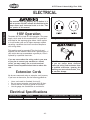
(('MFg\iXk`fe
The Model W1715 is wired for 110V operation. The power
supply circuit used for this machine MUST be grounded
and rated for the amperage given below. Never replace
a circuit breaker with one of higher amperage without
consulting a qualified electrician to ensure compliance
with wiring codes.
=`^li\-% 5-15 plug and receptacle.
This machine must be grounded! The electrical cord
supplied with this machine comes with a grounding pin. If
your outlet does not accommodate a ground pin, have it
replaced by a qualified electrician.
@]pflXi\lejli\XYflkk_\n`i`e^Zf[\j`epfliXi\X
fipflgcXekfZfee\ZkpflidXZ_`e\kfXj_Xi\[
Z`iZl`k#pfldXpZi\Xk\X]`i\fiZ`iZl`kfm\icfX[
_XqXi[ÇZfejlckXhlXc`]`\[\c\Zki`Z`Xekfi\[lZ\k_`j
i`jb%
<ok\ej`fe:fi[j
;FEFKnfibfepfli\c\Zki`ZXcjpjk\d
`] pfl Xi\ lejli\ XYflk \c\Zki`ZXc
Zf[\jXe[n`i`e^J\\bXjj`jkXeZ\]ifd
X hlXc`]`\[ \c\Zki`Z`Xe% @^efi`e^ k_`j
nXie`e^ZXeZXlj\\c\ZkifZlk`fe#]`i\#
fidXZ_`e\[XdX^\%
We do not recommend using an extension cord; however,
if you have no alternative, use the following guidelines:
•
•
•
•
Use a cord rated for Standard Service (S).
Do not use an extension cord longer than 50 feet.
Ensure that the cord has a ground wire and pin.
Use the gauge size listed below as a minimum.
<c\Zki`ZXcJg\Z`]`ZXk`fej
Fg\iXk`e^MfckX^\
8dg;iXn
D`e%:`iZl`kJ`q\
Gcl^&I\Zfdd\e[\[Gcl^
<ok\ej`fe:fi[
110V Operation
5 Amps
15A
NEMA 5-15
14 Gauge
-10-
N(.(,Fne\ijDXelXcD]^%J`eZ\)&'/
J<KLG
LegXZb`e^
This machine has been carefully packaged for safe
transportation. If you notice the machine has been
damaged during shipping, please contact your authorized
Shop Fox dealer immediately.
@em\ekfip
The following is a description of the main components
shipped with the Model W1715. Lay the components out
to inventory them.
@em\ekfip=`^li\. Hkp
8% Bandsaw (not shown) .....................................1
9% Stand Legs ..................................................2
:% Tool Tray ....................................................1
;% Corner Support Braces ....................................4
<% Wheels ......................................................2
=% Axle ..........................................................1
>% Wheel Mounting Bracket .................................1
?% Work Stop Rod .............................................1
@% Work Stop ...................................................1
A% Transport Handle ..........................................1
B% Pulley Cover ................................................1
C% V-Belt ........................................................1
D% Pulleys with Keys ..........................................2
E% Table .........................................................1
F% Table Support ..............................................1
?Xi[nXi\9X^efkj_fne
• Hex Wrench 4mm (Work Stop) ..........................1
• Hex Bolts M8-1.25 x 25 (Saw to Stand) ................6
• Hex Nuts M8-1.25 (Saw to Stand) .......................6
• Flat Washers 8mm (Saw to Stand) ......................6
• Hex Bolts M6-1 x 12 (Stand) .............................8
• Phillips Head Screws M6-1 x 12 (Tray) .................4
• Hex Nuts M6-1 (Stand, Tray, Table) ................... 13
• Flat Washers 6mm (Stand, Tray) ...................... 12
• Fender Washer 6mm (Table) .............................1
• Flat Head Screw M6-1 x 12 (Table) .....................1
• Cotter Pins (Axle & Handle) .............................4
-11-
G
B
D
F
C
N
O
E
I
J
K
M
L
H
=`^li\.%The loose parts shipped with the
bandsaw.
J<KLG
Efk\1 @]pflZXek]`e[Xe`k\dfek_`jc`jk#Z_\Zbk_\
dflek`e^cfZXk`fefek_\dXZ_`e\fi\oXd`e\k_\
gXZbX^`e^dXk\i`XcjZXi\]lccp%FZZXj`feXccpn\gi\$`ejkXcc
Z\ikX`eZfdgfe\ekj]fijX]\ij_`gg`e^%
B\\g dXZ_`e\ [`jZfee\Zk\[ ]ifd
gfn\ilek`c`ejkilZk\[fk_\in`j\%
N(.(,Fne\ijDXelXcD]^%J`eZ\)&'/
J<KLG
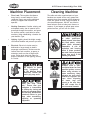
DXZ_`e\GcXZ\d\ek
=cffiCfX[1 This machine distributes a
heavy load in a small footprint. Some
residential floors may require additional
bracing to support both machine and
operator.
Nfib`e^:c\XiXeZ\j1 Consider existing and
anticipated needs, size of material to be
processed through the machine, and space
for auxiliary stands, work tables or other
machinery when establishing a location for
your Machine Type.
C`^_k`e^1 Lighting should be bright enough
to eliminate shadow and prevent eye strain.
<c\Zki`ZXc1Electrical circuits must be
dedicated or large enough to handle
amperage requirements. Outlets must be
located near each machine, so power or
extension cords are clear of high-traffic
areas. Follow local electrical codes for
proper installation of new lighting, outlets,
or circuits.
:c\Xe`e^DXZ_`e\
The table and other unpainted parts of your
bandsaw are coated with a waxy grease that
protects them from corrosion during shipment.
Clean this grease off with a solvent cleaner or
citrus-based degreaser. DO NOT use chlorinebased solvents such as brake parts cleaner or
acetone—if you happen to splash some onto a
painted surface, you will ruin the finish.
E<M<IZc\Xen`k_^Xjfc`e\
fi fk_\i g\kifc\ld$
YXj\[jfcm\ekj%Dfjk_Xm\
cfn ]cXj_ gf`ekj# n_`Z_
dXb\ k_\d \oki\d\cp
]cXddXYc\% 8 i`jb f]
\ogcfj`fe Xe[ Ylie`e^
\o`jkj `] k_\j\ gif[lZkj
Xi\lj\[%J\i`fljg\ijfeXc
`ealip dXp fZZli `] k_`j
nXie`e^`j`^efi\[
8CN8PJ nfib `e n\cc$
m\ek`cXk\[Xi\Xj]Xi]ifd
gfjj`Yc\ `^e`k`fe jfliZ\j
n_\e lj`e^ jfcm\ekj kf
Zc\Xe dXZ_`e\ip% DXep
jfcm\ekj Xi\ kfo`Z n_\e
`e_Xc\[ fi `e^\jk\[% Lj\
ZXi\ n_\e [`jgfj`e^
f] nXjk\ iX^j Xe[
kfn\cj kf Y\ jli\ k_\p
;F EFK Zi\Xk\ ]`i\ fi
\em`ifed\ekXc_XqXi[j%
LJ< _\cg\ij fi gfn\i
c`]k`e^ \hl`gd\ek kf
c`]k k_`j DXZ_`e\ EXd\%
Fk_\in`j\# j\i`flj g\i$
jfeXc`ealipdXpfZZli%
D8B< pfli j_fg ÈZ_`c[
jX]\%É <ejli\ k_Xk pfli
nfibgcXZ\ `j `eXZZ\jj`Yc\
kf Z_`c[i\e Yp Zcfj`e^ Xe[
cfZb`e^Xcc\ekiXeZ\jn_\e
pflXi\XnXp%E<M<IXccfn
lekiX`e\[ m`j`kfij `e pfli
j_fg n_\e Xjj\dYc`e^#
X[aljk`e^ fi fg\iXk`e^
\hl`gd\ek%
-12-
N(.(,Fne\ijDXelXcD]^%J`eZ\)&'/
8jj\dYcp
Although the main components of the E:AB8AJW1715
are assembled at the factory, some assembly is required.
The following series of instructions are the recommended
sequence best suited for the machine assembly.
KffcjE\\[\[
Hkp
Safety Glasses .....................................1 Per Person
Wrench 12mm ...................................................1
Wrench 14mm ...................................................1
Additional Person (for lifting).................................1
Sawhorses ........................................................2
Pliers ..............................................................1
Phillips Screwdriver #2 .........................................1
Straightedge 12" Minimum.....................................1
D8B< JLI< k_Xk pfli
dXZ_`e\ `j legcl^^\[
[li`e^ Xcc Xjj\dYcp
gifZ\[li\j @] k_`j
nXie`e^ `j `^efi\[#
j\i`flj g\ijfeXc `ealip
dXpfZZli%
Corner
Support
Brace
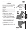
KfXjj\dYc\k_\YXe[jXn#[fk_\j\jk\gj1
Unfold the two stand leg assemblies. They are
hinged on the edges for easy setup.
)%
Use the M6-1 x 12 hex bolts, M6-1 hex nuts, and
6mm flat washers to install the corner support
braces in the bottom corners of the leg assemblies
(=`^li\ /).
*%
On one of the leg assemblies, attach the wheel
mounting bracket along with the corner support
braces to the outside bottom edge, as shown in
=`^li\/.
+%
Slide the axle through the holes in the wheel
mounting bracket.
,%
Slide the wheels onto the axle on the outside of the
mounting brackets, and secure them with the cotter
pins, as shown in =`^li\0.
Wheel
Mounting
Bracket
=`^li\/% Corner support brace and wheel
mounting bracket.
Cotter Pin
=`^li\0% Wheel installed with cotter pin.
-13-
J<KLG
(%
N(.(,Fne\ijDXelXcD]^%J`eZ\)&'/
-%
On the other leg, insert the handle into the predrilled holes and secure it with the cotter pins (see
=`^li\(').
Cotter
Pin
K_\ YXe[jXn `j X _\Xmp
dXZ_`e\ (++ cYj% Lj\
Xjj`jkXeZ\ Xe[ jX]\ c`]k`e^&
dfm`e^d\k_f[jn_\ec`]k`e^
k_`jdXZ_`e\%
J<KLG
.%
With the help of an assistant, lift the bandsaw onto
a pair of closely spaced sawhorses or other suitable
support (see =`^li\(().
/%
Attach the legs to the bandsaw with the M8-1.25 x
25 hex bolts, 8mm flat washers, and M8-1.25 hex
nuts. Tighten them with a 14mm wrench or socket
just enough to secure the parts. Final tightening will
take place when the stand is fully assembled.
0%
Remove the machine from the sawhorses, then
install the tool tray in the middle of the stand with
the M6-1 x 12 Phillips head screws, 6mm flat washers
and M6-1 hex nuts, as shown in =`^li\().
=`^li\('% Handle installed with cotter
pins.
('% Check to see if the bandsaw is relatively level, then
final tighten all the nuts.
=`^li\((% Attaching leg assemblies.
=`^li\()% Installing tool tray.
-14-
N(.(,Fne\ijDXelXcD]^%J`eZ\)&'/
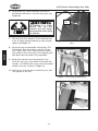
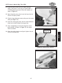
((% Place the pulley cover over the motor and gear
shafts, and secure it with the pre-installed M6-1 x
12 Phillips head screws and 12mm flat washers, as
shown in =`^li\(*.
()% Open the pulley cover, then insert the keys into the
slots on the pulley shafts.
(*% Slide the large diameter motor pulley onto the motor
shaft (see =`^li\(+).
(+% Install the worm gear pulley with the small diameter
wheel on the shaft closest to the gear box.
(,% Use a straightedge to check the alignment of the
pulley wheels, as shown in =`^li\(,, and adjust
them as needed.
(-% When the pulley wheels are aligned, tighten the set
screws on both pulleys.
=`^li\(*% Installing the pulley cover.
Motor Pulley
w/Key Slot
J<KLG
=`^li\(+% Motor pulley installed.
=`^li\(,% Checking the pulley alignment.
-15-
N(.(,Fne\ijDXelXcD]^%J`eZ\)&'/
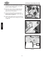
(.% Unthread the V-belt tension hex bolt, then pivot
the motor up and slide the V-belt into the pulley
grooves, as shown in =`^li\(-.
(/% Release the motor, letting its weight tension the
V-belt, then thread the V-belt tension hex bolt
against the side of the bandsaw.
(0% Install the work stop shaft into the side of the
bandsaw then lock it in place by tightening the set
screw, as shown in =`^li\(..
=`^li\(-% Installing the V-belt.
J<KLG
)'% Slide the work stop onto the end of the shaft and
lock it into position with the locking lever, as shown
in =`^li\(/.
V-belt Tension
Hex Bolt
=`^li\(.% Installing the work stop shaft.
Locking
Lever
=`^li\(/% Work stop locking lever
installed.
-16-
N(.(,Fne\ijDXelXcD]^%J`eZ\)&'/
K\jkIle
Once the assembly is complete, test run the machine to
make sure it runs properly for regular operations.
The test run consists of verifying the following: 1) The
motor powers up and runs correctly, and 2) the safety
disabling mechanism on the switch works correctly.
If, during the test run, you cannot easily locate the source
of an unusual noise or vibration, stop using the machine
immediately, then review KiflYc\j_ffk`e^ on GX^\*..
If you still cannot remedy a problem, contact our Tech
Support at (360) 734-3482 for assistance.
Gifa\Zk`c\j k_ifne ]ifd k_\ dXZ_`e\
Zflc[ ZXlj\ j\i`flj \p\ `ealip% N\Xi
jX]\kp ^cXjj\j kf i\[lZ\ k_\ i`jb f]
`ealip%
Kfk\jkilek_\dXZ_`e\#[fk_\j\jk\gj1
Read the entire instruction manual.
)%
Make sure all tools and foreign objects have been
removed from the machine.
*%
Connect the bandsaw to power.
+%
Put on safety glasses and secure loose clothing or
long hair.
,%
Raise the bandsaw by the handle.
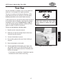
-%
Start the bandsaw while keeping your finger near
the ON/OFF switch at all times during the test run
(=`^li\(0). The bandsaw should run smoothly with
little or no vibration.
— If you suspect any problems, immediately stop the
bandsaw and correct before continuing.
-17-
J<KLG
(%
=`^li\(0% ON/OFF switch.
N(.(,Fne\ijDXelXcD]^%J`eZ\)&'/
FG<I8K@FEJ
>\e\iXc
This machine will perform many types of operations
that are beyond the scope of this manual. Many of these
operations can be dangerous or deadly if performed
incorrectly.
The instructions in this section are written with the
understanding that the operator has the necessary
knowledge and skills to operate this machine. @]XkXep
k`d\pflXi\\og\i`\eZ`e^[`]]`Zlck`\jg\i]fid`e^Xep
fg\iXk`fe#jkfglj`e^k_\dXZ_`e\
FG<I8K@FEJ
If you are an inexperienced operator, we strongly
recommend that you read books or trade articles, or
seek training from an experienced metal cutting bandsaw
operator before performing any unfamiliar operations.
8Yfm\Xcc#pflijX]\kpj_flc[Zfd\]`ijk
I<8;Xe[le[\ijkXe[k_`j\ek`i\`ejkilZ$
k`fe dXelXc Y\]fi\ lj`e^ k_`j dXZ_`e\%
J\i`flj g\ijfeXc `ealip dXp fZZli `]
jX]\kpXe[fg\iXk`feXc`e]fidXk`fe`jefk
le[\ijkff[ Xe[ ]fccfn\[% ;F EFK i`jb
pflijX]\kpYpefki\X[`e^
;FEFK`em\jk`^Xk\gifYc\djfiX[aljk
k_\ dXZ_`e\ n_`c\ `k `j ilee`e^% NX`k
lek`c k_\ dXZ_`e\ `j klie\[ F==#
legcl^^\[ Xe[ Xcc nfib`e^ gXikj
_Xm\Zfd\kfXZfdgc\k\jkfgY\]fi\
gifZ\\[`e^
8cnXpjn\XijX]\kp^cXjj\jn_\efg\i$
Xk`e^ k_`j dXZ_`e\% =X`cli\ kf Zfdgcp
dXpi\jlck`ej\i`fljg\ijfeXc`ealip%
-18-
N(.(,Fne\ijDXelXcD]^%J`eZ\)&'/
Fg\iXk`feK`gj
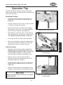
The following tips will help you safely and effectively
operate your bandsaw and help you get the maximum life
out of your saw blades.
?fi`qfekXc:lkk`e^
Use the work stop to quickly and accurately cut
multiple pieces of stock to the same length (see
=`^li\)').
•
Clamp the material firmly in the vise jaws to ensure
a straight cut through the material.
•
Allow the blade reach full speed before engaging
the workpiece. Never start a cut with the blade in
contact with the workpiece (see =`^li\)().
Chips should be curled and silvery. If the chips are
thin and powder like, increase your feed rate (refer
to the D\kXc:_`g@ejg\Zk`fe:_Xik on GX^\).).
•
If the chips are burned, reduce the blade speed.
•
Wait until the blade has completely stopped before
removing the workpiece from the vise, and avoid
touching the cut end—it could be very hot!
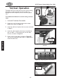
M\ik`ZXc:lkk`e^
•
Workpieces that cannot be properly supported or
stabilized without a vise should not be cut in the
vertical position. Examples are chains, cables, round
or oblong-shaped workpieces, workpieces with
internal or built-in moving or rotating parts, etc.
•
Make sure that the vertical table assembly is
securely fastened to the bandsaw frame so it will
adequately support the workpiece.
•
Always keep your fingers away from the blade and
always hold the workpiece securely in your hand
(=`^li\))).
•
Adjust the blade guides as close as possible to the
workpiece to minimize side-to-side blade movement.
NOTICE
Release the blade tension at the end of the day to
prolong blade life.
-19-
=`^li\)(% Proper bandsaw horizontal
starting position.
=`^li\))% Proper bandsaw vertical
starting position.
FG<I8K@FEJ
•
=`^li\)'% Work stop and lever.
N(.(,Fne\ijDXelXcD]^%J`eZ\)&'/
M\ik`ZXcFg\iXk`fe
The Model W1715 can easily be set up for vertical cutting
operations to make cuts that are not a straight cut
through the entire workpiece, such as curves or pattern
cuts.
Blade
Guide
Cover
KfXjj\dYc\k_\YXe[jXn]fim\ik`ZXcZlkk`e^#[fk_\j\
jk\gj1
(%
DISCONNECT BANDSAW FROM POWER!
)%
Remove the two flat head screws and the blade
guide cover shown in =`^li\)*.
=`^li\)*% Blade guide cover.
Install the table and replace the two screws removed
in Jk\g).
+%
Install the table bracket with the pre-installed hex
bolt, the M6-1 x 12 flat head screw, and the M6-1
hex nut, as shown in =`^li\)+.
,%
Place a level on the table, as shown in =`^li\),,
then use the adjustment bolt shown in =`^li\)- to
make the table level.
FG<I8K@FEJ
*%
Bolt Already
In Casting
=`^li\)+% Table and table bracket
installed.
=`^li\),% Adjusting table with a level.
Adjustment
Bolt
=`^li\)-% Table adjustment bolt.
-20-
N(.(,Fne\ijDXelXcD]^%J`eZ\)&'/
-%
Install the safety bracket and lock it in place with
the pin shown in =`^li\). to keep the saw from
falling.
Notch
Efk\1 Kf\ejli\k_\jX]\kpYiXZb\k]`kjj\Zli\cp`e
k_\efkZ_fek_\Yf[p]iXd\#k_\jX]\kpYiXZb\k
dXpe\\[kfY\jc`^_kcpdf[`]`\[n`k_X_Xdd\i
fifk_\iXggifgi`Xk\`dgc\d\ekkf]`kj\Zli\cp%
Safety
Bracket
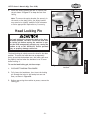
?\X[CfZb`e^G`e
Pin
K_\ _\X[ cfZb`e^ g`e j\Zli\j k_\ _\X[ `e k_\ [fne#
_fi`qfekXc gfj`k`fe% Pfl DLJK j\Zli\ k_\ _\X[ n`k_
k_\ cfZb`e^ g`e Y\]fi\ dfm`e^ k_\ dXZ_`e\ kf gi\$
m\ekk_\_\X[le\og\Zk\[cpjgi`e^`e^lg#ZXlj`e^k_\
dXZ_`e\ kf k`g fi ]Xcc% Fk_\in`j\# j\i`flj g\ijfeXc
`ealipfigifg\ikp[XdX^\Zflc[fZZli%
=`^li\).% Safety bracket in position.
Head Locking Pin
Kflj\k_\_\X[cfZb`e^g`e#[fk_\j\jk\gj1
=`^li\)/% Head locking pin correctly
installed.
(%
DISCONNECT BANDSAW FROM POWER!
)%
Fully lower the head down, then insert the locking
pin through the holes in the head pivot arm and
base, as shown in =`^li\)/.
*%
Before connecting the machine to power, remove the
locking pin.
-21-
FG<I8K@FEJ
The head locking pin safely secures the head in the down
position. To ensure the head does not unexpectedly
spring up and tip the bandsaw over, this locking pin must
be properly inserted when the bandsaw is not in use or
before moving it.
N(.(,Fne\ijDXelXcD]^%J`eZ\)&'/
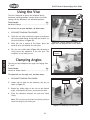
Lj`e^k_\M`j\
The vise is designed to secure the workpiece during
horizontal cutting operations. Always use the vise when
cutting with the bandsaw in the horizontal position.
KffcjE\\[\[
Hkp
Machinist's Square ..............................................1
FG<I8K@FEJ
Kflj\k_\m`j\fepfliYXe[jXn#[fk_\j\jk\gj1
(%
DISCONNECT BANDSAW FROM POWER!
)%
Check the vise with a machinist's square to make sure
the vise is perpendicular to the blade and reads 0˚ on
the scale as shown in =`^li\)0.
*%
When the vise is square to the blade, place the
material to be cut between the vise jaws.
+%
Turn the vise crank handle (=`^li\ *') clockwise to
firmly secure the workpiece in the vise jaws. The
workpiece is now ready to cut.
Scale
=`^li\)0% Using a machinist's square to
adjust the vise perpendicular to the blade.
Vise Crank
Handle
:cXdg`e^8e^c\j
The vise can hold workpieces for angle cuts ranging from
0˚ to 60˚.
KffcjE\\[\[
Hkp
Wrench or Socket 14mm .......................................1
KfX[aljkk_\m`j\]fiXe^c\Zlkj#[fk_\j\jk\gj1
(%
DISCONNECT BANDSAW FROM POWER!
)%
Loosen the hex bolts on the stationary vise jaw, as
shown in=`^li\*(.
=`^li\*'% Vise crank handle.
Hex Bolts
*% Rotate the sliding edge of the vise to the desired
angle, indicated by the scale, and secure the bolts.
+%
Place the workpiece between the jaws and clamp
firmly.
Efk\1 K_\m`j\aXnfek_\c\X[jZi\ng`mfkj]i\\cpkf
dXkZ_k_\Xe^c\f]k_\fk_\iaXn%
=`^li\*(% Loosening vise hex bolts.
-22-
N(.(,Fne\ijDXelXcD]^%J`eZ\)&'/
9cX[\>l`[\j
The blade guides should be as close to the workpiece as
possible. This will help ensure straight cuts by keeping the
blade from twisting and drifting off the cut line.
Adjustment Knob
Blade Guides
KfX[aljkk_\YcX[\^l`[\j#[fk_\j\jk\gj:
(%
DISCONNECT BANDSAW FROM POWER!
)%
Loosen the adjustment knob shown in =`^li\*) and
slide the blade guide as close to the workpiece as
possible, then re-tighten the knob.
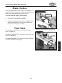
=\\[IXk\
=`^li\*)% Blade guide adjustment knob.
The feed rate is controlled by the spring and handle
shown in =`^li\**.
=fiJcfn\i=\\[IXk\1 Twist the handle clockwise to add
tension to the spring.
Spring
=fi=Xjk\i=\\[IXk\1 Twist the handle counterclockwise
to remove tension from the spring.
=`^li\**% Feed rate spring and handle.
-23-
FG<I8K@FEJ
Handle
N(.(,Fne\ijDXelXcD]^%J`eZ\)&'/
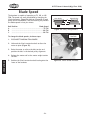
9cX[\Jg\\[
The bandsaw is capable of operating at 78, 108, or 180
FPM. The speed can easily be adjusted by changing the
V-belt placement. =`^li\*+ shows an illustration of each
pulley to belt combination, and the following list provides
the blade speeds in feet per minute.
9\ckGfj`k`fe
9cX[\Jg\\[
8
....................................................... 78 FPM
9
...................................................... 108 FPM
:
...................................................... 180 FPM
DfkfiGlcc\p
8
9
:
=`^li\*+% Pulley configurations.
V-belt Tension
Hex Bolt
KfZ_Xe^\k_\YcX[\jg\\[j#[fk_\j\jk\gj1
FG<I8K@FEJ
>\XiGlcc\p
(%
DISCONNECT BANDSAW FROM POWER!
)%
Unthread the V-belt tension hex bolt to allow the
motor to pivot (=`^li\*,).
*%
Raise the motor to relieve the belt tension and
position the belt in the desired pulley alignment.
+%
Release the motor and let the motor weight tension
the belt.
,%
Position the V-belt tension hex bolt back against the
frame of the bandsaw.
-24-
=`^li\*,% V-belt tension hex bolt.
N(.(,Fne\ijDXelXcD]^%J`eZ\)&'/
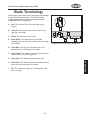
9cX[\K\id`efcf^p
Selecting the right blade for the cut requires a knowledge
of various blade characteristics. Use the illustration
in =`^li\*- and the following descriptions to better
understand blade characteristics.
A
B
8% B\i]1 The width of the cut by the blade during
cutting.
C
9% Kffk_J\k1 The amount each tooth is bent left or
right from the blade.
D
E
H
F
:% >Xl^\1 The thickness of the blade.
;% 9cX[\N`[k_1 The widest point of the blade
measured from the tip of the tooth to the back edge
of the blade.
G
I
=`^li\*-% Bandsaw blade components.
<% Kffk_IXb\1 The angle of the tooth from a line
perpendicular to the length of the blade.
=% >lcc\k;\gk_1 The distance from the tooth tip to the
bottom of the curved area (gullet).
>% Kffk_G`kZ_1 The distance between tooth tips.
@%
KG@1 The number of teeth per inch measured from
gullet to gullet.
-25-
FG<I8K@FEJ
?% 9cX[\9XZb1 The distance between the bottom of the
gullet and the back edge of the blade.
N(.(,Fne\ijDXelXcD]^%J`eZ\)&'/
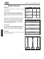
9cX[\J\c\Zk`fe
9cX[\J`q\
1
1
The Model W1715 accepts only ⁄2" x 0.025 x 64 ⁄2" blades.
Kffk_G`kZ_
Usually measured as TPI (Teeth Per Inch), tooth pitch
determines the size/number of the teeth. More teeth
per inch (fine pitch) will cut slower, but smoother; while
fewer teeth per inch (coarse pitch) will cut rougher, but
faster.
As a general rule, choose blades that will have at least
three teeth in the material at all times. Use fine pitched
blades on harder metals and coarse pitched blades on
softer metals. When selecting blades, refer to =`^li\*.
for recommended blade tooth (TPI) and speed (FPM)
based on the workpiece material.
Kffk_Jkpc\
DXk\i`Xc
Tool Steel
Stainless Steel
Bearing Bronze
Mild Steel
Hard Brass
Bronze
Soft Brass
Aluminum
Other Light Metals
=GD
24
78
18
108
14
180
=`^li\*.% Blade TPI and FPM chart.
Standard (or Raker)
Skip (or Skip Tooth)
When selecting blades, another option to consider is the
shape, gullet size, teeth set and teeth angle—otherwise
known as “Tooth Style." Many blade manufacturers offer
variations of the four basic styles shown in =`^li\*/.
FG<I8K@FEJ
KG@
Hook (or Claw)
Kffk_J\k
Three of the most common tooth sets are alternate, wavy,
and raker (see =`^li\*0).
Variable Pitch (VP)
=`^li\*/% Bandsaw blade tooth styles.
Alternate
Wavy
Raker
=`^li\*0% Bandsaw blade tooth sets.
-26-
N(.(,Fne\ijDXelXcD]^%J`eZ\)&'/
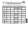
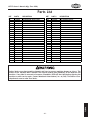
D\kXc:_`g@ejg\Zk`fe:_Xik
The best method of evaluating the performance of your metal cutting operation is to inspect the chips
that are formed from cutting. Refer to the chart below for chip inspection guidelines.
:_`g
8gg\XiXeZ\
:_`g
:fcfi
9cX[\
Jg\\[
=\\[
Gi\jjli\
Thin & Curled
Silver
>ff[
>ff[
Hard, Thick &
Short
Brown or Blue
Decrease
Decrease
Lubricate with
a small amount
of oil
Hard, Strong &
Thick
Brown or Blue
Decrease
Decrease
Lubricate with
a small amount
of oil
Hard, Strong &
Thick
Silver or Light
Brown
>ff[
Decrease
Slightly
Check Blade
Pitch
Hard & Thin
Silver
Increase
Decrease
Check Blade
Pitch
Straight & Thin
Silver
>ff[
Increase
Powdery
Silver
Decrease
Increase
Curled Tight &
Thin
Silver
>ff[
Decrease
=`^li\+'. Metal chip inspection chart.
-27-
8[[`k`feXc
8Zk`fej
Check Blade
Pitch
FG<I8K@FEJ
:_`g
;\jZi`gk`fe
N(.(,Fne\ijDXelXcD]^%J`eZ\)&'/
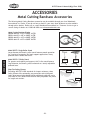
8::<JJFI@<J
D\kXc:lkk`e^9Xe[jXn8ZZ\jjfi`\j
The following Metal Cutting Bandsaw accessories may be available through your local Woodstock
International Inc. Dealer. If you do not have a dealer in your area, these products are also available
through online dealers. Please call or e-mail Woodstock International Inc. Customer Service to get a
current listing of dealers at: 1-800-840-8420 or at [email protected].
D\kXc:lkk`e^9Xe[jXn9cX[\j
;**)'Ç-+$(&)o(&)o'%'),('KG@
;**)(Ç-+$(&)o(&)o'%'),(+KG@
;**))Ç-+$(&)o(&)o'%'),(/KG@
;**)*Ç-+$(&)o(&)o'%'),)+KG@
FG<I8K@FEJ
Df[\c;)).*J`e^c\Ifcc\iJkXe[
Large diameter ball bearing roller stand features smooth operation
for a variety of processing and work support applications. Heavy
pedestal base is stable and secure.
Df[\c;)).+,Ifcc\iJkXe[
For greater work stability and support, this 5 roller stand features
large diameter, ball bearing rollers mounted on a sturdy adjustable
pedestal base.
J_fg=foJX]\kp>cXjj\j
Exceeding ANSI Z87.1-1989 standards for impact resistance, these
Safety Glasses offer outstanding eye protection and stylish good
looks. Wrap-around side shields provide additional protection and a
wide field of view. Model D2676 features easily adjustable ear pieces
for length and comfort.
-28-
D2273
D2274
D2675
D2676
N(.(,Fne\ijDXelXcD]^%J`eZ\)&'/
D8@EK<E8E:<
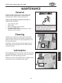
>\e\iXc
Regular periodic maintenance on your machine will
ensure its optimum performance. Make a habit of
inspecting your machine each time you use it.
:_\Zb]fik_\]fccfn`e^Zfe[`k`fejXe[i\gX`ifi
i\gcXZ\n_\ee\Z\jjXip1
Loose mounting bolts.
Worn switch.
Worn or damaged cords and plugs.
Damaged bandsaw blade.
Any other condition that could hamper the safe
operation of this machine.
D8B< JLI< k_Xk pfli dXZ_`e\ `j
legcl^^\[ [li`e^ Xcc dX`ek\eXeZ\ gif$
Z\[li\j@]k_`jnXie`e^`j`^efi\[#j\i`$
fljg\ijfeXc`ealipdXpfZZli%
:c\Xe`e^
Frequently use a brush and a shop vacuum to remove
chips and other debris from the machine. Keep the nonpainted surfaces rust-free with regular applications of an
anti-rust protectorate.
Periodically, remove the blade and thoroughly clean all
metal chips or built-up grease from the wheel surfaces
and blade housing.
Vise
Screw
=`^li\+(% Vise screw.
D8@EK<E8E:<
ClYi`ZXk`fe
Before applying lubricant to any area, wipe the area clean
to avoid contamination. Lubricate the vice screw shown in
=`^li\+( with multi-purpose gear grease.
Remove the cover on the gearbox shown in =`^li\+) and
coat the gears with multi-purpose gear grease.
Gearbox
Cover
=`^li\+)% Gearbox cover.
-29-
N(.(,Fne\ijDXelXcD]^%J`eZ\)&'/
J<IM@:<
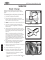
9cX[\:_Xe^\
Blades should be changed when they become dull,
damaged, or when your operation requires a different
blade.
KfZ_Xe^\k_\YcX[\fek_\YXe[jXn#[fk_\j\jk\gj1
(%
DISCONNECT BANDSAW FROM POWER!
)%
Raise the head of the bandsaw to the vertical
position, use the head locking pin to hold it in place,
then remove the wheel access cover.
*%
Loosen the tension knob and slip the blade off of the
wheels.
+%
Install the new blade through both blade guide
bearings, as shown in =`^li\+*, and around the
bottom wheel.
,%
Hold the blade around the bottom wheel with one
hand and slip it around the top wheel with the other
hand, keeping the blade between the blade guide
bearings.
=`^li\+*% Installing the blade.
Efk\1 @k`jjfd\k`d\jgfjj`Yc\kf]c`gk_\YcX[\
`ej`[\flk#`en_`Z_ZXj\k_\YcX[\n`ccY\`ejkXcc\[
`ek_\nife^[`i\Zk`fe%:_\ZbkfdXb\jli\k_\
YcX[\k\\k_Xi\]XZ`e^kfnXi[k_\nfibg`\Z\#Xj
j_fne`e=`^li\++#X]k\idflek`e^kfk_\YXe[jXn%
Jfd\YcX[\jn`cc_Xm\X[`i\Zk`feXcXiifnXjX
^l`[\%
J<IM@:<
Blade
Guide
Bearings
-%
When the blade is around both wheels, adjust the
position so the back of the blade is against the
shoulder of the wheels (see =`^li\+,).
.%
Tighten the tension knob so the blade will not slip on
the wheels upon start up.
/%
Connect the bandsaw to the power source.
0%
Briefly turn the bandsaw FE then F== to position
the blade and resume the previous tracking.
Bla
de
Tra
ve
l
=`^li\++% Correct blade travel.
Shoulder
—If the tracking needs to be adjusted, see 9cX[\
KiXZb`e^ in the next section.
—If the tracking is fine, proceed to 9cX[\K\ej`fe on
GX^\*).
-30-
=`^li\+,% Blade installed on the top
wheel.
N(.(,Fne\ijDXelXcD]^%J`eZ\)&'/
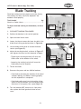
9cX[\KiXZb`e^
The blade tracking has been properly set at the factory.
The tracking will rarely need to be adjusted if the
bandsaw is used properly.
KffcjE\\[\[
Hkp
Wrench or Socket 14mm .......................................1
KfX[aljkk_\YcX[\kiXZb`e^fek_\YXe[jXn#[fk_\j\
jk\gj1
(%
DISCONNECT BANDSAW FROM POWER!
)%
Position the bandsaw in the vertical position.
*%
Open the wheel access cover.
+%
Loosen, but do not remove the lower hex bolt in the
blade wheel tilting mechanism shown in =`^li\+-.
,%
Use the blade tension knob to release the blade
tension (see =`^li\+.).
-%
Adjust the tracking hex bolt, as shown in =`^li\+.,
then tighten the lower hex bolt loosened in Jk\g+.
Lower
Hex Bolt
=`^li\+-% Blade wheel tilting lower hex
bolt.
—Tightening the tracking hex bolt will move the
blade closer to the shoulder of the wheel.
Tracking
Hex Bolt
Blade
Tension
Knob
—Loosening the tracking hex bolt will move the
blade away from the shoulder.
.%
Tension the blade.
/%
Reconnect the power and turn FE the bandsaw.
=`^li\+.% Adjusting the tracking hex bolt.
—If the blade tracks along the shoulder of the wheel
(without rubbing), the blade is tracking properly
and this adjustment is completed.
0%
Turn the bandsaw F==, disconnect it from power,
then replace the blade guard and wheel access
cover.
-31-
J<IM@:<
—If the blade walks away from the shoulder of the
wheel or hits the shoulder, turn the bandsaw F==,
disconnect it from power, then repeat Jk\gj+$/.
N(.(,Fne\ijDXelXcD]^%J`eZ\)&'/
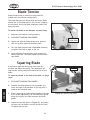
9cX[\K\ej`fe
Proper blade tension is essential to long blade life,
straight cuts, and efficient cutting times.
Two major signs that you do not have the correct blade
tension are: 1) The blade stalls in the cut and is slipping
on the wheels, and 2) the blade frequently breaks from
being too loose.
Kfk\ej`fek_\YcX[\fek_\YXe[jXn#[fk_\j\jk\gj1
(%
Make sure the blade is tracking properly.
)%
DISCONNECT BANDSAW FROM POWER!
*%
Loosen and slide the blade guides as far apart as
they will go then tighten them down again.
+%
Turn the blade tension knob in =`^li\+/ clockwise
to tighten the blade as tight as you can.
,%
Blade
Tension Knob
=`^li\+/% Blade tension knob.
Using moderate finger pressure, push against the
side of the blade. The blade should not move more
than 0.004".
JhlXi`e^9cX[\
It is always a good idea during the life of your saw
to check and adjust this setting. This adjustment will
improve your cutting results and extend the life of your
blade.
Hex Bolt
J<IM@:<
Kf jhlXi\ k_\ YcX[\ kf k_\ Y\[ f] k_\ kXYc\# [f k_\j\
jk\gj1
(%
DISCONNECT BANDSAW FROM POWER!
)%
Separate the blade guides as far as possible, the
lower the head of the bandsaw all the way until it
contacts the horizontal stop.
*%
Place a square on the table bed and against the edge
of the blade (=`^li\+0), and check different points
along the length of the table between the blade
guides.
+%
Loosen the hex bolt shown in =`^li\+0, and rotate
the seat until the blade is vertical to the bed, then
re-tighten the hex bolt.
-32-
=`^li\+0% Squaring the blade.
N(.(,Fne\ijDXelXcD]^%J`eZ\)&'/
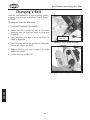
9cX[\>l`[\9\Xi`e^j
The blade guide bearings must be properly adjusted to
make square cuts. One bearing on each assembly has an
eccentric bushing that allows it to be adjusted so the
blade is square to the vise. The bearings are secured
in place by a hex nut and lock washer, as shown in
=`^li\,'.
Backing Bearing
Before adjusting the blade guide bearings, make sure that
you have squared the blade to the table as discussed in
the previous section.
Hex
Nut
KfX[aljkk_\YcX[\^l`[\Y\Xi`e^j#[fk_\j\jk\gj1
Eccentric Bushing
(%
DISCONNECT BANDSAW FROM POWER!
)%
Position the vise to 90°, then lock it in place.
*%
Put a machinist's square against the face of the vise
and move it over to the blade.
=`^li\,'% Blade guide adjustment
controls.
— The square should evenly touch both the face of
the vise and the blade. If it does, skip ahead to
Jk\g-.
— If the square does not evenly touch the blade, but
it does evenly touch the vise, continue with the
next step.
+%
Loosen the hex nuts that secure the eccentric
bushings attached to the guide bearings.
,%
Adjust the bearings as necessary to force the blade
to be 90° to the vise, then re-tighten the hex nuts.
-%
If any of the bearings are not touching the blade
evenly, loosen the hex nuts and adjust them so the
contact surface of the bearings touch the blade
evenly.
.%
Adjust the backing bearing in the same manner, but
leave a gap between 0.002-0.003" from the back of
the blade.
-33-
J<IM@:<
Efk\1 J`eZ\k_\Y\Xi`e^jkn`jkk_\YcX[\`ekf
gfj`k`fe#`k`jXZZ\gkXYc\`]k_\i\`j'%''($'%'')
^XgY\kn\\ek_\YcX[\Xe[k_\]ifekfiYXZbf]
k_\Y\Xi`e^%AljkdXb\jli\efkkfjhl\\q\k_\
YcX[\kffk`^_kcpn`k_k_\Y\Xi`e^j%8]k\ik_\^l`[\
Y\Xi`e^jXi\j\k#pflj_flc[Y\XYc\kfifkXk\k_\
^l`[\Y\Xi`e^jXck_fl^_k_\pn`ccY\jk`]] n`k_
pfli]`e^\ij%
N(.(,Fne\ijDXelXcD]^%J`eZ\)&'/
:_Xe^`e^M$9\ck
Check the V-belt periodically for signs of glazing, cracking,
or fraying. If any of these conditions are present, change
the V-belt.
KfZ_Xe^\k_\M$Y\ck#[fk_\j\jk\gj1
(%
DISCONNECT BANDSAW FROM POWER!
)%
Loosen the V-belt tension hex bolt on the motor
mounting plate to allow the motor to pivot (see
=`^li\,().
*%
Open the pulley cover door to access the V-belt, as
shown in =`^li\,).
+%
Pivot the motor towards the gear box to release belt
tension and remove the V-belt.
,%
Replace the V-belt and let the weight of the motor
provide the tension.
-%
Secure the V-belt tension bolt.
V-Belt Tension
Hex Bolt
=`^li\,(% V-belt tension hex bolt.
J<IM@:<
=`^li\,)% Installing the V-belt.
-34-
N(.(,Fne\ijDXelXcD]^%J`eZ\)&'/
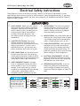
<c\Zki`ZXcJX]\kp@ejkilZk`fej
These pages are current at the time of printing. However, in the spirit of improvement, we may
make changes to the electrical systems of future machines. Study this diagram carefully. If you notice
differences between your machine and these wiring diagrams, call Woodstock International Technical
Support at (360) 734-3482.
(% J?F:B?8Q8I;% Working on wiring that is
connected to a power source is extremely
dangerous. Touching electrified parts will
result in personal injury including but not
limited to severe burns, electrocution,
or death. Disconnect the power from
the machine before servicing electrical
components!
,% DFKFIN@I@E>% The motor wiring shown
in these diagrams is current at the time
of printing, but it may not match your
machine. Always use the wiring diagram
inside the motor junction box.
-% DF;@=@:8K@FEJ% Using aftermarket parts or
modifying the wiring beyond what is shown
in the diagram may lead to unpredictable
results, including serious injury or fire.
)% HL8C@=@<;<C<:KI@:@8E% Due to the
inherent hazards of electricity, only a
qualified electrician should perform wiring
tasks on this machine. If you are not a
qualified electrician, get help from one
before attempting any kind of wiring job.
*% N@I<:FEE<:K@FEJ% All connections must
be tight to prevent wires from loosening
during machine operation. Double-check all
wires disconnected or connected during any
wiring task to ensure tight connections.
+% N@I<&:FDGFE<EK;8D8><% Damaged
wires or components increase the risk of
serious personal injury, fire, or machine
damage. If you notice that any wires or
components are damaged while performing
a wiring task, replace those wires or
components before completing the task.
.% :8G8:@KFIJ&@EM<IK<IJ% Some capacitors
and power inverters store an electrical
charge for up to five minutes after being
disconnected from the power source. To
avoid being shocked, wait at least this long
before working on these components.
/% <C<:KI@:8CI<HL@I<D<EKJ% You MUST
follow the electrical requirements at the
beginning of this manual when connecting
your machine to a power source.
0% <OG<I@<E:@E>;@==@:LCK@<J% If you are
experiencing difficulties understanding
the information included in this section,
contact our Technical Support at (360) 7343482.
WIRING DIAGRAM COLOR KEY
BLUE
WHITE
BROWN
GREEN
GRAY
YELLOW
YELLOW
GREEN
PURPLE
RED
ORANGE
PINK
-35-
LIGHT
BLUE
BLUE
WHITE
TURQUOISE
J<IM@:<
The photos and diagrams
included in this section are
best viewed in color. You
can view these pages in
color at www.shopfox.biz.
BLACK
N(.(,Fne\ijDXelXcD]^%J`eZ\)&'/
<c\Zki`ZXc:fdgfe\ekj
Power Cord
=`^li\,*% ON/OFF switch wiring.
=`^li\,+% Start capacitor.
N`i`e^;`X^iXd
Read
Page 35
JKFG
Before
Wiring
Capacitor
35MFD 250VAC
110V
Motor
Ground
J<IM@:<
Switch
Ground
WARNING
ACCIDENTAL INJURY
HAZARD!
Disconnect power
supply before
adjustments, setup,
or maintenance!
Neutral
Hot
110V NEMA 5-15
(As Recommended)
-36-
N(.(,Fne\ijDXelXcD]^%J`eZ\)&'/
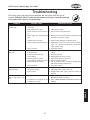
KiflYc\j_ffk`e^
This section covers the most common problems and corrections with this type of
machine. N8IE@E>;FEFKdXb\XepX[aljkd\ekjlek`cgfn\i`j[`jZfee\Zk\[Xe[
dfm`e^gXikj_Xm\Zfd\kfXZfdgc\k\jkfg
GIF9C<D
GFJJ@9C<:8LJ<
:FII<:K@M<8:K@FE
Machine does not start or a 1. Plug/receptacle is at fault or wired
breaker trips.
incorrectly.
2. Start capacitor is at fault.
3. Motor connection wired incorrectly.
4. Power supply is at fault/switched
OFF.
1. Test for good contact or correct the wiring.
2. Test/replace if faulty.
3. Correct motor wiring connections.
4. Make sure all hot lines/grounds are operational and
have correct voltage on all legs.
5. Replace faulty ON button or ON/OFF switch.
5. ON/OFF switch is at fault.
6. Wiring is open/has high resistance. 6. Troubleshoot wires for internal/external breaks;
check for disconnected/corroded connections;
repair/replace wiring.
7. Test/repair/replace.
7. Motor is at fault.
Machine stalls or is under- 1. Wrong blade for the workpiece
powered.
material (metal).
2. Feed rate too fast for task.
3. V-belt slipping.
4. Blade is slipping on wheels.
5. Pulley/sprocket slipping on shaft.
6. Motor bearings are at fault.
7. Motor is at fault.
Machine has vibration or 1. V-belt is slapping belt cover.
noisy operation.
2. V-belt worn or loose.
3. Pulley is loose.
1. Use blade with correct properties for your type of
cutting.
2. Decrease feed rate.
3. Replace bad V-belt and re-tension.
4. Adjust blade tracking and tension.
5. Replace loose pulley/shaft.
6. Test by rotating shaft; rotational grinding/loose
shaft requires bearing replacement.
7. Test/repair/replace.
1. Inspect belt cover for proper installation.
2. Inspect/replace belt with a new one.
3. Realign/replace shaft, pulley, setscrew, and key as
required.
Machine is loud when cut- 1. Excessive feed rate.
1. Refer to Feed Rate on Page 23, or Blade Speed on
ting or bogs down in the
Page 24 and adjust as required.
cut.
2. The blade TPI is too great, or the 2. Refer to Blade Selection on Page 26 and adjust as
required.
material is too coarse.
J<IM@:<
-37-
N(.(,Fne\ijDXelXcD]^%J`eZ\)&'/
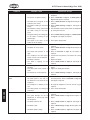
GIF9C<D
Blades break often.
GFJJ@9C<:8LJ<
:FII<:K@M<8:K@FE
1. The workpiece is loose in the vise.
1. Clamp the workpiece tighter, or use a jig to hold the
workpiece.
2. Refer to Feed Rate on Page 23, or Blade Speed on
Page 24 and adjust as required.
3. Refer to Blade Selection on Page 26 and adjust as
required.
4. Refer to Blade Tracking on Page 31, and adjust as
required.
5. Start bandsaw and then slowly lower the headstock
by setting the feed rate.
2. The feed or cut speed is wrong.
3. The blade TPI is too great, or the
material is too coarse.
4. The blade is rubbing on the wheel
flange.
5. The bandsaw is being started with
the blade resting on the workpiece.
6. The guide bearings are misaligned, 6. Refer to Blade Tracking on Page 31, or Blade Guides
on Page 23, and adjust as required.
or the blade is rubbing on the
wheel flange.
7. The blade is too thick, or the 7. Use a higher quality blade.
blades are of low quality.
Blade dulls prematurely.
2.
3.
4.
5.
6.
Blade wears on one side.
1. Refer to Blade Speed on Page 24 and adjust as
required.
2. Refer to Blade Selection on Page 26 and adjust as
The blade TPI is too coarse.
required.
The blade feed pressure is too 3. Refer to Feed Rate on Page 23, and adjust as
required.
light.
The workpiece has hard spots, 4. Increase the feed pressure, and reduce the cutting
speed.
welds, or scale is on the material.
5. Replace the blade.
The blade is twisted.
The blade is slipping on the 6. Refer to Blade Tension on Page 32, and adjust as
required.
wheels.
1. The cutting speed is too fast.
1. The blade guides are worn or mis- 1. Refer to Blade Guides on Page 23 and replace or
adjust.
adjusted.
2. The blade guide slide bracket is 2. Tighten the blade guide bracket.
loose.
3. Refer to Blade Tracking on Page 31, and adjust as
3. The wheels are out of alignment.
required.
J<IM@:<
Teeth are ripping from the 1. The feed pressure is too heavy and 1. Refer to Blade Selection on Page 26 and decrease
blade.
the feed pressure. Refer to Feed Rate on Page 23,
the blade speed is too slow; or
and adjust as required.
the blade TPI is too coarse for the
workpiece.
2. The workpiece is vibrating in the 2. Re-clamp the workpiece in the vise, and use a jig if
required.
vise.
3. The blade gullets are loading up 3. Use a coarser-tooth blade.
with chips.
The cuts are crooked.
1. Refer to Feed Rate on Page 23, and adjust as
required.
The guide bearings are out of 2. Refer to Blade Guides on Page 23 and replace or
adjust.
adjustment, or too far away from
the workpiece.
3. Refer to Blade Tension on Page 32, and adjust as
The blade tension is low.
required.
4. Refer to Blade Change on Page 30 and replace the
The blade is dull.
blade.
5. Refer to Blade Speed on Page 24 and adjust as
The blade speed is wrong.
required.
1. The feed pressure is too high.
2.
3.
4.
5.
-38-
N(.(,Fne\ijDXelXcD]^%J`eZ\)&'/
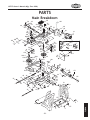
G8IKJ
DX`e9i\Xb[fne
20
101
104
52
51
103
109
108
80
87
92
94
73
106
107
91
86
81
76 7
67 87
16
75
35
10
71
35-1
35-4
56-1
56
56-2
132
126A-1
126A
35-5
35-2 35-3
70
114
61
63
62
61
60
64
69
68
89
87
88
72
58
57
3
67
66
9 65
85
120
110
20
51
12
90
179
79
182
75
117
98
83
84 75
93
96
99
185
183 180
178
112
171
72
58A-1
113
58A
55
68
118
186
59A-1
77
9
7
59A
54
11
59
15
45
52
20
28
48
47
46
50
51
17
43
122
33
157
51
52
21 19
8
51
156
184
24
181
176
3
18
22
40
175
2
12
67
26
1
174
44
39
27
5
53
37
30
32
52
51
49
36
85
34
11
12
4
23
173
13
14
1
3
6
-39-
172
170
177
2
G8IKJ
7
N(.(,Fne\ijDXelXcD]^%J`eZ\)&'/
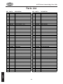
GXikjC`jk
PART #
DESCRIPTION
REF
PART #
DESCRIPTION
XPB02M
XPN01M
XPW03M
X1715004
X1715005
X1715006
XPS14M
X1715008
XPW03M
XPFH19M
XPB20M
XPN03M
X1715013
X1715014
X1715015
X1715016
X1715017
X1715018
X1715019
XPSS04M
X1715021
X1715022
X1715023
XPN06M
X1715026
X1715027
X1715028
XPR47M
X1715032
X1715033
X1715034
X1715035
X1715035-1
X1715035-2
X1715035-3
X1715035-4
X1715035-5
XPB01M
X1715037
X1715039
X1715040
X1715043
X1715044
X1715045
X1715046
HEX BOLT M6-1 X 12
HEX NUT M6-1
FLAT WASHER 6MM
STAND LEG (RIGHT)
WHEEL ASSY
COTTER PIN
PHLP HD SCR M6-1 X 12
LOCKING LEVER
FLAT WASHER 6MM
FLAT HD SCR M4-.7 X 10
HEX BOLT M8-1.5 X 35
HEX NUT M8-1.25
STAND LEG (LEFT)
TRANSPORT HANDLE
ADJUSTING ROD
MOTOR CORD
PIVOTING ROD
SUPPORT PLATE
WORK STOP
SET SCREW M6-1 X 12
STOCK STOP ROD
WIRE RELIEF RETAINER
SWITCH
HEX NUT M5-.8
SWITCH PANEL
ADJUSTING ROD SUPPORT
HAND WHEEL
EXT RETAINING RING 13MM
LEADSCREW M16-4 X 358
VISE NUT M6-4
FRONT VISE JAW
MOTOR 3/4HP 110V 1PH
MOTOR FAN COVER
MOTOR FAN
CAPACITOR COVER
CAPACITOR 35M 250V
JUNCTION BOX
HEX BOLT M10-1.5 X 30
BED
SCALE
ELECTRIC CORD COVER
GASKET
POWER CORD
NUT PLATE
SPRING ADJUST SCREW M5-.8 X 40
47
48
49
50
51
52
53
54
55
56
56-1
56-2
57
58
58A
58A-1
59
59A
59A-1
60
61
62
63
64
65
66
67
68
69
70
71
72
73
75
76
77
79
80
81
83
84
85
86
87
88
X1715047
XPS38M
X1715049
XPSS14M
XPW01M
XPB07M
XPB43M
X1715054
X1715055
X1715056
XPWF06M
XPN01M
X1715057
X1715058
XPS09M
XPW02M
X1715059
X1715059A
X1715059A-1
XPR39M
XP629ZZ
X1715062
X1715063
X1715064
X1715065
X1715066
XPLW04M
XPFH02M
X1715069
XPN03M
X1715071
X1715072
XPK12M
XPS14M
X1715076
X1715077
X1715079
X1715080
X1715081
XPB07M
X1715084
XPW04M
X1715086
XP6202ZZ
X1715088
EXTENSION SPRING 22 x 4.5 x 215
PHLP HD SCR M4-.7 X 10
REAR VISE JAW
SET SCREW M8-1.25 X 12
FLAT WASHER 8MM
HEX BOLT M8-1.25 X 25
HEX BOLT M12-1.75 X 75
PIVOT
TABLE
TABLE BRACKET
FENDER WASHER 6MM
HEX NUT M6-1
ADJUSTABLE BRACKET (TOP)
KNOB BOLT M10-1.5 X 25
PHLP HD SCR M5-.8 X 10
FLAT WASHER 5MM
BLADE BACK SAFETY COVER
PLATE
KNOB M6-1 X 8
EXT RETAINING RING 8MM
BALL BEARING 629ZZ
GUIDE PIVOT
BEARING SHAFT PIN 8 X 40MM
BLADE ADJUSTABLE SEAT
ADJUSTABLE BRACKET
GUIDE BEARING LOCK
LOCK WASHER 8MM
FLAT HD SCR M6-1 X 12
BLADE GUARD
HEX NUT M8-1.25
BLADE WHEEL (FRONT)
BLADE WHEEL BEARING COVER
KEY 5 X 5 X 30
PHLP HD SCR M6-1 X 12
SWITCH CUT OFF TIP
BLADE WHEEL (REAR)
BLADE TENSION KNOB
COMPRESSION SPRING 14.5 X 2 X 76
BODY FRAME
HEX BOLT M8-1.25 X 25
MOTOR MOUNT PLATE
FLAT WASHER 10MM
MOTOR PULLEY
BALL BEARING 6202ZZ
BEARING BUSHING
G8IKJ
REF
1
2
3
4
5
6
7
8
9
10
11
12
13
14
15
16
17
18
19
20
21
22
23
24
26
27
28
30
32
33
34
35
35-1
35-2
35-3
35-4
35-5
36
37
39
40
43
44
45
46
-40-
N(.(,Fne\ijDXelXcD]^%J`eZ\)&'/
GXikjC`jk
REF
PART #
DESCRIPTION
REF
PART #
DESCRIPTION
89
90
91
92
93
94
96
98
99
101
103
104
106
107
108
109
110
112
113
114
117
118
120
X1715089
X1715090
X1715091
X1715092
X1715093
X1715094
X1715096
XPB166M
X1715099
X1715101
X1715103
XPB20M
X1715106
X1715107
X1715108
X1715109
X1715110
X1715112
X1715113
XPW01M
XPW03M
XPR05M
XP6202ZZ
OIL SEAL
TRANSMISSION WHEEL SHAFT
TRANSMISSION GEAR
GEAR BOX GASKET
GEAR BOX COVER
WORM GEAR
BEARING BUSHING
HEX BOLT M8-1.25 X 50
BUSHING
WORM GEAR PULLEY
BLADE TENSION PLATE
HEX BOLT M8-1.25 X 35
SLIDING PLATE DRAW BLOCK
BLADE WHEEL SHAFT
SHAFT BLOCK
BLADE TENSION SLIDING GUIDES
MOTOR PULLEY COVER
V-BELT 3L215
BLADE 1/2 X .025 X 64-1/2
FLAT WASHER 8MM
FLAT WASHER 6MM
EXT RETAINING RING 15MM
BALL BEARING 6202ZZ
122
126A
126A-1
132
156
157
170
171
172
173
174
175
176
177
178
179
180
181
182
183
184
185
186
XPN09M
XP6202ZZ
XPR21M
X1715132
XPS22M
XPLW01M
X1715170
XPB10M
XPN01M
XPW03M
X1715174
X1715175
X1715176
X1715177
X1715178
XLABEL-12
X1715180
XLABEL-04
X1715182
X1715183
X1715184
X1715185
X1715186
HEX NUT M12-1.75
BALL BEARING 6202ZZ
INT RETAINING RING 35MM
BLADE SAFE GUARD
PHLP HD SCREW M5-.8 X 25
LOCK WASHER 5MM
TOOL PLATE
HEX BOLT M6-1 X 25
HEX NUT M6-1
FLAT WASHER 6MM
WHEEL STAND
COTTER PIN
AXLE
CORNER BRACKET
MACHINE ID LABEL
READ MANUAL LABEL
SAFETY GLASSES LABEL
ELECTRICITY LABEL
UNPLUG MACHINE LABEL
RPM LABEL
BLADE TRAVEL LABEL
BLADE SAFETY LABEL
TIPPING HAZARD LABEL
JX]\kp cXY\cj nXie XYflk dXZ_`e\ _XqXi[j Xe[ _fn kf gi\m\ek dXZ_`e\ [XdX^\ fi `ealip% K_\
fne\i f] k_`j dXZ_`e\ DLJK dX`ekX`e k_\ fi`^`eXc cfZXk`fe Xe[ i\X[XY`c`kp f] Xcc cXY\cj fe k_`j
dXZ_`e\%@]XepcXY\c`ji\dfm\[fiY\Zfd\jlei\X[XYc\#I<GC8:<k_XkcXY\cY\]fi\Xccfn`e^k_\
dXZ_`e\kf\ek\ij\im`Z\X^X`e%:fekXZkNff[jkfZb@ek\ieXk`feXc#@eZ%Xk(*-').*+$*+/)finnn%
j_fg]fokffcj%Zfdkffi[\ie\ncXY\cj%
G8IKJ
-41-
-42-
N(.(,Fne\ijDXelXcD]^%J`eZ\)&'/
FOLD ALONG DOTTED LINE
Place
Stamp
Here
NFF;JKF:B@EK<IE8K@FE8C@E:%
G%F%9FO)*'0
9<CC@E>?8D#N80/)).$)*'0
FOLD ALONG DOTTED LINE
TAPE ALONG EDGES--PLEASE DO NOT STAPLE
N8II8EKP
N8II8EKP
Nff[jkfZb@ek\ieXk`feXc#@eZ%nXiiXekjXccJ_fg=fodXZ_`e\ipkfY\]i\\f][\]\Zkj]ifdnfibdXej_`g
Xe[dXk\i`Xcj]fiXg\i`f[f]knfp\Xij]ifdk_\[Xk\f]fi`^`eXcgliZ_Xj\Ypk_\fi`^`eXcfne\i%
K_`jnXiiXekp[f\jefkXggcpkf[\]\Zkj[l\[`i\Zkcpfi`e[`i\Zkcpkfd`jlj\#XYlj\#e\^c`^\eZ\fi
XZZ`[\ekj#cXZbf]dX`ek\eXeZ\#fii\`dYlij\d\ekf]k_`i[gXikp\og\ej\j`eZlii\[%
Nff[jkfZb@ek\ieXk`feXc#@eZ%n`cci\gX`ifii\gcXZ\#Xk`kj\og\ej\Xe[Xk`kjfgk`fe#k_\J_fg=fo
dXZ_`e\fidXZ_`e\gXik#n_`Z_`eefidXclj\_Xjgifm\ekfY\[\]\Zk`m\#gifm`[\[k_Xkk_\fi`^`eXc
fne\ii\kliejk_\gif[lZkgi\gX`[kfXJ_fg=fo]XZkfipj\im`Z\Z\ek\in`k_giff]f]k_\`igliZ_Xj\
f]k_\gif[lZkn`k_`eknfp\Xij#Xe[gifm`[\jNff[jkfZb@ek\ieXk`feXc#@eZ%i\XjfeXYc\fggfikle`kpkf
m\i`]pk_\Xcc\^\[[\]\Zkk_ifl^_`ejg\Zk`fe%@]`k`j[\k\id`e\[k_\i\`jef[\]\Zk#fik_Xkk_\[\]\Zk
i\jlck\[]ifdZXlj\jefkn`k_`ek_\jZfg\f]Nff[jkfZb@ek\ieXk`feXc@eZ%jnXiiXekp#k_\ek_\fi`^`eXc
fne\idljkY\Xik_\Zfjkf]jkfi`e^Xe[i\klie`e^k_\gif[lZk%
K_`j`jNff[jkfZb@ek\ieXk`feXc#@eZ%jjfc\ni`kk\enXiiXekpXe[XepXe[XccnXiiXek`\jk_XkdXp
Y\`dgc`\[YpcXn#`eZcl[`e^Xepd\iZ_XekXY`c`kpfi]`ke\jj#]fiXepgXik`ZlcXigligfj\#Xi\_\i\Yp
c`d`k\[kfk_\[liXk`fef]k_`jni`kk\enXiiXekp%N\[fefknXiiXekk_XkJ_fg=fodXZ_`e\ipZfdgc`\j
n`k_k_\gifm`j`fejf]XepcXnfiXZkj%@eef\m\ekj_XccNff[jkfZb@ek\ieXk`feXc#@eZ%jc`XY`c`kple[\i
k_`jnXiiXekp\oZ\\[k_\gliZ_Xj\gi`Z\gX`[]fik_\gif[lZk#Xe[Xepc\^XcXZk`fejYifl^_kX^X`ejk
Nff[jkfZb@ek\ieXk`feXc#@eZ%j_XccY\ki`\[`ek_\JkXk\f]NXj_`e^kfe#:flekpf]N_XkZfd%N\j_Xcc
`eef\m\ekY\c`XYc\]fi[\Xk_#`eali`\jkfg\ijfejfigifg\ikpfi]fi`eZ`[\ekXc#Zfek`e^\ek#jg\Z`Xcfi
Zfej\hl\ek`Xc[XdX^\jXi`j`e^]ifdk_\lj\f]fligif[lZkj%
<m\ip\]]fik_XjY\\edX[\kf\ejli\k_XkXccJ_fg=fodXZ_`e\ipd\\kj_`^_hlXc`kpXe[[liXY`c`kp
jkXe[Xi[j%N\i\j\im\k_\i`^_kkfZ_Xe^\jg\Z`]`ZXk`fejXkXepk`d\Y\ZXlj\f]fliZfdd`kd\ekkf
Zfek`elfljcp`dgifm\k_\hlXc`kpf]fligif[lZkj%
=^\]FjVa^inBVX]^cZhVcYIddah
LddYhidX`XVgg^Zhi]djhVcYhd[egdYjXihidbZZii]ZcZZYhd[idYVnh
lddYldg`ZghVcYbZiValdg`Zgh#6h`ndjYZVaZgVWdjidi]Zg[^cZ
egdYjXih[gdbLddYhidX`>ciZgcVi^dcVa!>cX#