1
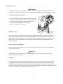
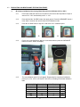
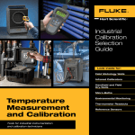
MILWAUKEE ELECTRIC TOOL CORPORATION – TEST & MEASUREMENT PRODUCT REPAIR SERVICE INSTRUCTIONS — CALIBRATION 2266-20 Laser TEMP-GUN™ Thermometer Environmental Condition Calibration and verification are performed at an ambient temperature of 23°C ~ 25°C and ambient relative humidity <55% in a controlled room. Each thermometer should be uniquely identified as to the room and/or area in which it is used or tested. REPAIR SERVICE INSTRUCTIONS Calibration MILWAUKEE TOOL 13135 WEST LISBON ROAD ● BROOKFIELD, WISCONSIN 53005-2550 ● USA 58-92-2266d3 03/2014 www.milwaukeetool.com TABLE OF CONTENTS Page Introduction 1 Precautions and Safety Information 1 Symbols 1 Safety 2 Specifications 3 General Specifications 3 Basic Maintenance 4 Loading / Changing the Batteries 4 Maintaining Tool 4 Cleaning the Laser Windows 4 Scope 5 Equipment Use 5 Testing Condition and Interference 5 Field calibration Procedure 5 IR Software Calibration Check 5 IR Software Calibration Check - continued 6 KTC Software Calibration Check using Temperature Calibration 7 i Introduction WARNING To avoid shock or injury, do not perform the verification tests or calibration procedures described in the manual unless you are qualified to do so. The information provided in this document is for the use of qualified personnel only. CAUTION The 2266-20 contain parts that can be damaged by static discharge. Follow the standard practices for handling static sensitive devices. Precautions and Safety Information Use the Laser TEMP-Gun™ only as described in the Operator’s Manual. If you do not do so, the protection provided by the Laser TEMP-Gun™ may be impaired. Read the “Safety Information” page before servicing this product. In this manual, a WARNING identifies conditions and actions that pose hazard (s) to the user; a CAUTION identifies conditions and actions that may damage the Gun or the test instruments. The Symbols The symbols used on the Laser TEMP-GUN™ and in this manual are explained in Table 1. Table A. The Symbols Symbol Meaning Volts Direct Current CAUTION Laser Light - Do Not Stare Into Beam Laser Product - Avoid Exposure: Laser Radiation Is Emitted From This Aperture Refer to the manual, Important information. + + Battery Do not discard this product or throw away. 1 SAFETY Review the following safety precautions to avoid injury and prevent damage to this product or products connected to it. To avoid potential hazards, use the product only as specified. WARNING: These statements identify conditions or practices that could result in personal injury or loss of life. CAUTION: These statements identify conditions or practices that could result in damage to the equipment or other property. Specific precautions To reduce the risk of injury, user must read and understand operator’s manual. Laser light - Do not stare into beam or view directly with optical instruments. Do not point laser light at others. Laser light can cause eye damage. Avoid exposure to laser radiation. Laser may emit hazardous radiation. Do not point laser at reflective surfaces. Unpredictable results may occur. Do not operate in wet/damp conditions. To avoid electric shock, do not operate this product in wet or damp conditions. 2 SPECIFICATIONS All specifications are warranted unless noted typical and apply to the 2266-20 Laser TEMP-GUN™ Thermometer. Stated accuracies are at 23°C±5°C at than 80% relative humidity and without the battery indicator displayed. General specifications Laser Type: Class II <1mW 630-670 nm -30°C to 500°C (-22°F to 932°F) -30°C to 10°C (-22°F to 50°F): ±1.5°C (3°F) 10°C to 30°C (50°F to 86°F): ±1.0°C (2°F) 30°C to 380°C (86°F to 716°F): ±1.5°C (3°F) or 1.5% of reading, whichever is greater 380°C to 500°C (716°F to 932°F): ±2°C (4°F) or 2% of reading, whichever is greater *Assume ambient operating temperature of 23°C to 25°C (73°F to 77°F) Min. measuring distance: 2” < 50°C (122°F), 4” > 50°C (122°F) Display resolution: 0.1°C (0.1°F) Contact temperature range: -30°C to 450°C (-22°F to 842°F) Contact temperature input accuracy: ± 2°C (± 4°F) Temperature display resolution: 0.1°C/°F in Primary, 1°C/°F in Secondary Emissivity: 0.95 Response time: <500 msec Spectral response: 8 to 14μm Distance to spot: 12 to 1 Drop: 1.5 meter Repeatability: ±0.5% OR ±1°C(±2°F) (whichever is greater) Operating temperature: 0°c to 50°C (32°F to 122°F) Storage temperature: -20°C to 60°C (-4°F to 140°F) w/o battery Relative humidity: 10 to 90% RH non-condensing at <30°C ambient Voltage: 4.5 DC Battery life: Greater than 12 hrs with all functions Max Power: Wavelength: IR Temperature range: IR Accuracy: 3 Basic Maintenance WARNING To reduce the risk of injury, always remove the batteries from the tool before performing any maintenance. Never disassemble the tool. Contact a MILWAUKEE service facility for ALL repairs. Loading/Changing the Batteries 1. Press in the battery door lock and open the battery door. 2. Before installing batteries for the first time, remove the white, rectangular tag in the battery compartment. 3. Insert three (3) AA batteries, as displayed. 4. Close the battery door securely. Maintaining Tool Keep your tool in good repair by adopting a regular maintenance program. After six months to one year, depending on use, return the tool to a MILWAUKEE service facility for repairs. If the tool does not start or operate at full power with fully charged batteries, clean the contacts on the battery door. If the tool still does not work properly, return the tool to a MILWAUKEE service facility for repairs. Cleaning the Laser Windows Clean the laser windows with a soft, moist cloth to keep them clean and clear. Remove battery pack before cleaning. WARNING To reduce the risk of personal injury and damage, never immerse your tool in liquid or allow a liquid to flow inside it. Cleaning Clean dust and debris from tool. Keep tool handles clean, dry and free of oil or grease. Use only mild soap and a damp cloth to clean the tool since certain cleaning agents and solvents are harmful to plastics and other insulated parts. Some of these include gasoline, turpentine, lacquer thinner, paint thinner, chlorinated cleaning solvents, ammonia and household detergents containing ammonia. Never use flammable or combustible solvents around tools. 4 1.0 TESTING PERSONNEL QUALIFICATION: 1.1 2.0 Testing personnel are required to be knowledgeable of the procedures in this manual. EQUIPMENT USE: 2.1 Below is Recommended Reference Thermometer Traceable to NIST: Manufacturer Model No. Range Accuracy Hart Scientific 1502A -200°C to 962°C ±0.006°C accuracy at 0°C 2.2 Below are recommended IR Black Bodies Sources / TC Calibrator: Manufacturer Model No. Range Accuracy Emissivity Target Size Hart Scientific 9133 -35°C~+150°C ±0.4°C accuracy at 100°C 0.95(±0.02) 2.0in(50mm) Hart Scientific 4181 35°C ~ +500°C ±0.5°C accuracy at 100°C 0.90~0.95(±0.02) 6.0in(152mm) Fluke TC 714 -200°C ~ +1370°C ±0.5°C accuracy at 100°C NA NA Fluke 5500A -200°C ~ +1370°C ±0.16°C accuracy at 100°C NA NA Fluke 5520A -200°C ~ +1370°C ±0.16°C accuracy at 100°C NA NA 2.3 3.0 Operate only the test equipment within its calibration period. TESTING CONDITION AND INTERFERENCE: 3.1 Calibration and verification are performed at an ambient temperature of 23°C ~ 25°C and ambient relative humidity <55% in a controlled room. Each thermometer should be uniquely identified as to the room and/or area in which it is used or tested. 3.2 If the meter is exposed to significant changes in ambient temperature (hot to cold or cold to hot) allow 3 hours for the unit to acclimate with room temperature before taking any temperature reading or calibration. 3.3 Operate the unit under test (UUT) and the reference thermometer within its specified range. 3.4 Calibration can be verified using a certified NIST traceable standard thermometer. Recalibration must be performed in similar environment conditions as it was calibrated to get similar results. 3.5 Strong electromechanical radiation or static discharges can cause reading errors if situated near the meter. 3.6 The object size under test should be larger than the spot size calculated by the field of view diagram of the meter. 5 4.0 PRODUCTION CALIBRATION AND TESTING PROCEDURE: 4.1 IR Software Calibration Check using Black Body Source (Calibrator 9133 or 4181) 4.1.1 Put all units inside the control room for about 3 hours where the temperature is kept at around 23°C --25°C and humidity is 40% +/- 10% 4.1.2 Press and hold the “ALARM” button, then apply power. Press the “MEASURE” button 4 times. After 5 seconds, the unit will enter into IR calibration mode. 4.1.3 Press the “ALARM” button to skip 25°C and move to 0°C calibration point. 4.1.4 Put the unit on the test fixture. Wait for 3-4 seconds and then press the “MEASURE” button to confirm. “PASS” will display 4.1.5 The next calibration point 50°C will appear. Repeat step3 to complete all calibration points (0°C, 50°C, 100°C, 250°C,450°C and -20°C) according to the below calibration table. Blackbody [°C] 0 50 100 250 450 -20 Distance [inch] 3 2 10 10 12 3 6 Stable Time (sec) 5 5 5 3 3 5 Fluke 9133 9133 4181 4181 4181 9133 4.2 4.1.6 You can skip any calibration points by pressing “ALARM” button until the unit will exit and turn off. 4.1.7 Once exit, the unit will default to Normal temperature Mode. KTC Software Calibration Check using Temperature Calibrator (Fluke 714 or 5500A/5520A) 4.2.1 Condition the unit to be calibrated in a stable environment as described in 3.1 to ensure they are in thermal equilibrium. 4.2.2 Set the Fluke714 or 5500A/5520A to be 0°C and “K” type mode. 4.2.3 Connect the KTC cable to Fluke714 or 5500A/5520A. Press and hold the “ALARM” button, then apply power. Press the “MEASURE” button 4 times. After 5 seconds, the unit will enter into KTC calibration mode. 4.2.4 Wait 60s for first point to stable and Press the “MEASURE” button to confirm. The next calibration point 50°C will appear. 4.2.5 Set the Fluke714 or 5500A/5520A to 50°C. Wait for 30 seconds and then press the “MEASURE” button to confirm. (For retest, the stable time is 10s). 4.2.6 Repeat steps 4.2.4~4.2.5 to complete all calibration points per table below. Calibration points Stable time for calibration Stable time for retest Fluke 0 (Thermocouple) 60s 60s 714 or 5500A/5520A 50 (Thermocouple) 30s 10s 714 or 5500A/5520A 100 (Thermocouple) 30s 10s 714 or 5500A/5520A 250 (Thermocouple) 30s 10s 714 or 5500A/5520A 450 (Thermocouple) 30s 10s 714 or 5500A/5520A -20 (Thermocouple) 30s 10s 714 or 5500A/5520A 4.2.7 You can skip any calibration points by pressing “ALM” button until the unit will exit and turn off. 4.2.8 Once exit, the unit will default to Normal Temperature Mode. 7