1
CLARION PRODUCT REGISTRATION INFORMATION
For USA and Canada only
www.clarion.com
Dear Customer:
Congratulations on your purchase of a Clarion mobile electronic products. We are confident that
you'll enjoy your Clarion experience.
There are many benefits to registering your product. We invite you to visit our website at www.
clarion.com to register your Clarion product.
We have made product registration simple with our easy to use website. The registration form
is short and easy to complete. Once you're registered, we can keep you informed of important
product information.
Register at www.clarion.com - it's easy to keep your Clarion product up to date.
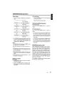
Contents
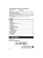
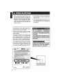
1. FEATURES
2. CONTROLS
MAIN UNIT
3. NOMENCLATURE
Names of the Buttons and Their Functions
Display Items
LCD Screen
4. PRECAUTIONS
5. HANDLING COMPACT DiSCS
6. DCP (Detachable Control Panel)
7.
8.
9.
10.
11.
2
3
3
4
4
5
5
6
7
8
OPERATIONS
Basic Operations
Radio Mode Operations
CD/MP3IWMA Mode Operations
OTHER OPERATIONS
TROUBLESHOOTING
ERROR DISPLAYS
SPECIFICATIONS
9
9
12
14
20
22
23
24
·
• Auxiliary Audio Input
• CD-R, CD-RW, WMA, & MP3 Compatible
• Rotary Volume Control & HD Display
[Q]DO~~
DIGITAL AUDIO
mp3
ID3TAG
Be sure to unfold and read the next page.
Veuillez depiier et VGUS referer la page suivante.
Assicurarsi di aprire e leggere la pagina successiva.
Cerciorese de desplegar y de leer fa pagina siguiente.
a
2
M275
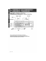
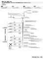
MAIN UNIT I
LI
APPARECCHIO PRINCIPALE I UNIDAD PRINCIPAL
[CD SLOT]
[DIRECT] [ROM]
[SCN]
----[SRC]
[ROTARY]
[~] ---+'--~H::J7H~":~~4~f7=d~~~4~~J~
clarion
[0] -~~ ~,~~~r~
[.1']
--~~I\\\
[lSR] ...................................................
I;:;;;;;jt;;;;±:i'.;;;=±:t:;;.9~
~=l
[AUX]
Note: Be sure to unfold this page and refer to the front diagrams as you read each chapter.
Remarque: Veuiliez dsplier certe page et vous referer aux scMmas quana VGUS lisez cnaque cnapitre.
Nota: Assicurarsi di aprire questa pagina efare riferimento a questi diagrammi quando si legge ciascun capitolo.
Nota: Cuando lea los capitulos despliegue esta pagil1a y consulte los diagramas.
l
3
M275
Note:
• Be sure to read this chapter referring to the front diagrams of chapter "2. CONTROLS" on page 3 (unfold).
Names of the Buttons and Their Functions
[RELEASE] button
[ROM] button
• Press the [RELEASE] button to unlock the
detachable panel.
• Perform random play while in the CD/MP3IWMA
mode.
• Press and hold the button for 1 second or
longer to perform all random play while in the
MP3IWMA mode.
[~] button
• Eject a CD when it is loaded in the unit.
[0] button
• During Radio mode, switch the display indication
in the following order:
Main Display ~Clock Display~ Main Display...
• During CD/AUX mode, switch the display
indication (Main Display, Clock Display).
• During MP3IWMA mode,switch the display
indication in the following order:
Track No./Play Time ~ Folder No./Play Time
~ Track Name ~ Folder Name ~ Title Tag ~
Album Tag ~ Artist Tag ~ Clock Display ~
Track No./Play Time...
• Press and hold the button for 1 second or longer
to enter the Adjustment mode.
[J'] button
• Use the button to enter to the Sound mode.
(Z-Enhancer, Bass, Treble, Balance, Fader).
• Press and hold for 1 second or longer to turn
on or off the M-B EX mode.
[lSR] button
• Recall ISR radio station in memory.
• Press and hold for 2 seconds or longer: Store
current station into ISR memory (Radio mode
only).
[DIRECT] buttons
• Store a station into memory or recall it directly
while in the Radio mode.
[SCN] button
• Perform scan play for 10 seconds of each track
while in the CD/MP3IWMA mode.
• Press and hold the button for 1 second or longer
to perform all scan play while in the MP3IWMA
mode.
[RPT] button
• Repeat play while in the CD/MP3IWMA mode.
• Press and hold the button for 1 second or longer
to perform all repeat play while in the MP3IWMA
mode.
4
M275
[UP], [ON] buttons
• Select the folder (MP3IWMA disc only).
[ ..... ], [~] buttons
• Seek a station while in the Radio mode or select
a track when listening to a CD. These buttons
are used to make various settings.
• Press and hold the button for 1 second or longer
to enter the fast-forward or fast-backward in
CD/MP3IWMA mode.
[ ~ II] button
• Perform preset scan while in the Radio mode.
Press and hold the button for 2 seconds or
longer to perform auto store.
• Play or pause a track while in the CD/MP3IWMA
mode.
• Perform second level adjustment or selection.
[SRC] button
• Press the button to turn on the power.
Press and hold the button for 1 second or longer
to turn off the power.
• Switch the Operation mode among the Radio
mode, CD/MP3IWMA mode and AUX mode.
[BND] button
• Switch the band, or seek tuning or manual
tuning while in the Radio mode.
• Play the first track while in the CD/MP3IWMA
mode.
• Press and hold the button for 1 second or
longer to select CD-DA or MP3IWMA on a Multisession disc.
[ROTARY] knob
• Adjust the volume by turning the knob clockwise
or counterclockwise.
• Use the knob to perform various settings.
Names of the Buttons and Their Functions
[CD SLOT]
[AUX] input
• CD insertion slot.
• Auxiliary jack insertion.
Display Items
Operation status indication
Main Display, Clock, etc. are displays
Preset channel
indication (1 to 6)
I
: M-B EX (MAGNA BASS EX)
indication
: Z- Enhancer indication
mIl : Enter indication
STIli: Stereo indication
(II
MANU : Manual indication
~ : All tracks indication
ROM : Random indication
RPT : Repeat indication
SeN : Scan indication
LCD Screen
In extreme cold, the screen movement may slow down and the screen may darken, but this is normal.
The screen will recover when it returns to normal temperature.
M275
5
When it is very cold in the boat and the unit is
used soon after switching on the heater, the
disc and the optical components may become
fogged and not operate properly. Wipe fogged
discs with a soft cloth. Fogged optical components will naturally return to normal when the
unit is left for about one hour after which it will
operate normally.
This equipment has been tested and found to
comply with the limits for a Class 8 digital device,
pursuant to Part 15 of the FCC Rules.
These limits are designed to provide reasonable
protection against harmful interference in a residential installation.
This equipment generates, uses, and can radiate
radio frequency energy and, if not installed and
used in accordance with the instructions, may
cause harmful interference to radio communications. However, there is no guarantee that interference will not occur in a particular installation.
If this equipment does cause harmful interference to radio or television reception, which can
be determined by turning the equipment off and
on, the user is encouraged to consult the dealer
or an experienced radiofTV technician for help.
(E:
MODEL
M275
2. When the boat is underway in rough water the
sound may skip as a result of intense vibrations and shock.
3. This unit uses a precision mechanism. Even in
the event that trouble arises, never open the
case, disassemble the unit, or lubricate the
rotating parts.
USE OF CONTROLS, ADJUSTMENTS,
OR PERFORMANCE OF PROCEDURES
OTHER THAN THOSE SPECIFIED HEREIN,
MAY RESULT IN HAZARDOUS RADIATION
EXPOSURE.
THE COMPACT DISC PLAYER SHOULD NOT
BE ADJUSTED OR REPAIRED BY ANYONE
EXCEPT PROPERLY QUALIFIED SERVICE
PERSONNEL.
"t"i·Jjl"k,·l·'t'li·Jj'U-i#j;t
CHANGES OR MODIFICATIONS TO THIS
PRODUCTNOTAPPROVEDBYTHEMAN~
FACTURER WILL VOID THE WARRANTY
AND WILL VIOLATE FCC APPROVAL.
clarion
12V e GROUND ~8~O~:5:~1~~~~~;ik~~/8l~~~~~~~~~HZ
===
15A Load 40 AUSTRALIA: AM 531-1629kHz/FM 87.0-108MHz
THIS DEVICE COMPLIES WITH PART 15 OF THE FCC RULES.
OPERATION IS SUBJECT TO THE FOLLOWING TWO CONDITIONS:
(1) THIS DEVICE MAY NOT CAUSE HARMFUL INTERFERENCE, AND
(2) THIS DEVICE MUST ACCEPT ANY INTERFERENCE RECEIVED, INCLUDING
INTERFERENCE THAT MAY CAUSE UNDESIRED OPERATION.
THIS PRODUCTION COMPLIES WITH DHHS RULES 21 CFR SUBCHAPTER
J APPLICABLE AT DATE OF MANUFACTURE.
CLARION CO.,LTD.
50 KAMITODA,TODA-SHI,SAITAMA-KEN,JAPAN
This product includes technology owned by Microsoft Corporation and cannot
be used or distributed without a license from MSLGP
----------
I
I
CLASS 1 LASER PRODUCT
0051 722 877
MANUFACTURED: CLARION MALAYSIA
SERIAL No.
PE-3008B
6
M275
Bottom View of Source Unit
(f)F
276-0277-00
Clarion Co.,Ltd.
MADE IN MALAYSIA
This unit has been designed specificall~ for
playback of compact discs bearing the rdlD~ffi1
mark. No other discs can be played.
DIGITAL AUDIO
Note on compact discs
Never stick labels on the surface of the compact
disc or mark the surface with a pencil or pen.
To remove the compact disc from its storage
case, press down on the center of the case and
lift the disc out, holding it carefully by the edges.
Removing the disc
Proper way to hold
the compact disc
Always handle the compact disc by the edges.
Never touch the surface.
To remove fingermarks and dust, use "a soft cloth,
and wipe in a straight line from the center of the
compact disc to the circumference.
Do not use any solvents such as commercially
available cleaners, anti-static spray, or thinner to
clean compact discs.
No
Do not use compact discs that have large scratches, are misshapen, or cracked, etc. Use of such
discs will cause misoperation or damage.
New discs may have some roughness around
the edges. The unit may not work or the sound
may skip if such discs are used. Use a ball-point
pen, etc. to remove roughness from the edge of
the disc.
Roughness
Do not expose compact discs to direct sunlight or
any heat source.
r
Note:
• Do not use commercially available CD protection sheets or discs equipped with stabilizers, etc. These may
get caught in the internal mechanism and damage the disc.
M275
7
The control panel can be detached to prevent
theft. When detaching the control panel, store it
in the DCP (Detachable Control Panel) case to
prevent scratches.
We recommend taking the DCP with you when
leaving the boat.
Storing the DCP in the DCP case
Hold the DCP, in the orientation as shown in the
figure below, and put it into the supplied DCP
case. (Ensure the DCP is in the correct orientation.)
DCP
Removing the DCP
1. Press the [SRC] button for 1 second or longer
to switch off the power.
2. Press in the [RELEASE] button.
DCP case
* The DCP is unlocked
•
The DCP can easily be damaged by impact.
After removing it, be careful not to drop it
or subject it to strong shocks.
•
When the Release button is pressed and the
DCP is unlocked, the intense vibration and
stock may cause it to fall. To prevent damage to the DCP, always store it in its case
after detaching it. (See figure above.)
•
The connector connecting the main unit and
the DCP is an extremely important part. Be
careful not to damage it by pressing on it
with fingernails, pens, screwdrivers, etc.
3. Remove the DCP.
Main Unit Front
Attaching the DCP
1. Insert the right side of the DCP into the main
unit.
2. Insert the left side of the DCP to attach into the
main unit.
Note:
• If the DCP is dirty, wipe off the dirt with a soft, dry
cloth only.
8
M275
Basic Operations
Note: Be sure to read this chapter referring to the front diagrams of
chapter "2. CONTROLS" on page 3 (unfold).
• Radi.o mode
Be sure to lower the volume before switching off the unit power or the ignition key. The
unit remembers its last volume setting. If
you switch the power off with the volume up,
when you switch the power back on, the sudden loud volume may hurt your hearing and
damage the unit.
Turning on/off the power
Note:
• Be careful about using this unit for a long time
without running the engine. If you drain the boat's
battery too much, you may not be able to start the
engine and this can reduce the service life of the
battery.
Main Display -+ Clock Display -+ Main Display...
• CD mode
Main Display (Track No., Play Time)-+
Clock Display -+ Main Display...
• MP3IWMA mode
Main-1 Display (Track No., Play Time)-+
Main-2 Display (Folder No., Play Time) -+
Track -+ Folder -+ Title -+ Album -+ Artist -+
Clock Display -+ Main-1 Display...
• AUX mode
Main Display -+ Clock Display -+ Main Display...
*
1. Press the [SRC] button.
2. The illumination and display on the unit light
up. The unit automatically remembers its last
Operation mode and will automatically switch
to display that mode.
3. Press and hold the [SRC] button for 1 second
or longer to turn off the power for the unit.
Selecting a mode
1. Press the [SRC] button to change the Operation mode.
2. Each time you press the [SRC] button, the Operation mode changes in the following order:
Radio mode -+ CD/MP3JWMA mode -+
AUX mode -+ Radio mode...
Note:
• If the CD mode is selected when no disc is inserted,
the display shows "NO DISC".
Once selected, the preferred display becomes the
display default. When a function adjustment such
as volume is made, the screen will momentarily
switch to that function's display, then revert back
to the preferred display several seconds after the
adjustment.
Adjusting the volume
Turning the [ROTARY] knob clockwise increases
the volume; turning it counterclockwise decreases the volLime. "VOL XX" will be displayed where
"XX" is the volume level from 0 (minimum) to 33
(maximum).
*
The factory default setting for volume is "VOL
13".
Sound mode adjustments
1. Press the [.1'] button to enter the Sound Adjustment mode.
2. Press the [ ...... , ~] button to select the
"item name".
"Z-EHCR"
Switching the display
Press the [D] button to select the desired display.
Each time you press the [D] button, the display
switches in the following order:
t
t
"TREBLE"
t
"BALANCE"
t
"FADER"
"BASS"
M275
9
Basic Operations
3. Turning the [ROTARY] knob to adjust the
selected Sound mode.
Z-EHCR
Selection type
: OFF ~ B-BOOST ~
IMPACT~ EXCITE ~OFF. ..
BASS
Adjustment range: -7 to +7
TREBLE
Adjustment range: -7 to +7
BALANCE:
Adjustment range: LEFT 12 to RIGHT 12
FADER
:
Adjustment range: FRONT 12 to REAR 12
Notes:
• If no operation is performed for more than 10 seconds, the Audio mode is cancelled and returns to
the previous mode.
• Bass and Treble can only be adjusted when the
"Z-EHCR" is off.
Setting the Z-Enhancer
This unit is provided with 3 types of sound tone
effects stored in memory. Select the one you prefer.
2-1. Press the [ ...... , ~] button and select "ZEHCR".
3-1. Turning the [ROTARY] knob to change to the
following sound tone effect.
"OFF"
t
3-1. Turning the [ROTARY] knob clockwise emphasizes the bass; turning it counterclockwise attenuates the bass.
"BASS XX" will be displayed where "XX" is
the value from -7 to +7.
Note:
• The factory default setting is "BASS 0".
Adjusting the treble
2-1. Press the [ ...... , ~] button and select
"TREBLE".
3-1. Turning the [ROTARY] knob clockwise emphasizes the bass; turning it counterclockwise attenuates the bass.
"TREB XX" will be displayed where "XX" is
the value from -7 to +7.
Note:
• The factory default setting is "TREB 0".
Adjusting the balance
2-1. Press the [ ...... , ~ ] button and select
"BALANCE".
3-1. Turning the [ROTARY] knob clockwise emphasizes the sound from the right speaker;
turning it counterclockwise emphasizes the
sound from the left speaker.
"B-BOOST"
The display changes as follows:
"IMPACT"
"RIGHT XX" will be displayed where "XX" is
the value from 1 to 12.
"EXCITE"
"LEFT XX" will be displayed where "XX" is
the value from 1 to 12.
t
t
• OFF
: no sound effect
• B-BOOST: b~ emphasized
(~;:r indicator lights in the display)
• IMPACT
: b~ and treble emphasized
(~;r indicator lights in the display)
• EXCITE
: bass and treble emphasized mid
de-emphasized
((~) indicator lights in the display)
Note:
• The factory default setting is "OFF".
10
Adjusting the bass
2-1. Press the [ ...... , ~] button and select
"BASS".
M275
Notes:
• When Balance is 0, "CENTER" will be displayed
instead.
• The factory default setting is "CENTER".
Basic Operations
Adjusting the fader
2-1. Press the [ ~ , ~] button and select
"FADER".
3-1. Turning the [ROTARY] knob clockwise emphasizes the sound from the front speakers;
turning it counterclockwise emphasizes the
sound from the rear speakers.
Notes:
• Use only the 3.5mm stereo jack for the AUX jack
input.
• Volume can be adjusted through the unit. If you
face difficulties of hearing sound even after volume
has been adjusted, please refer section "Selecting
AUX IN sensitivity" on page 20 for details.
The display change's as follows:
"FRONT XX" will be displayed where "XX" is
the value from 1 to 12.
"REAR XX" will be displayed where "XX" is
the value from 1 to 12.
Notes:
• When Fader is 0, "CENTER" will be displayed
instead.
'
Connect external music
player via 3.5mm stereo
jack
• The factory default setting is "CENTER".
Adjusting MAGNA BASS EX
The MAGNA BASS EX does not adjust the low
sound area like the normal sound adjustment
function, but emphasizes the deep bass sound
area to provide you with a dynamic sound.
1. Press and hold the [J'] button for 1 second
or longer to turn on the MAGNA BASS EX effect.
M$X indicator lights in the display.
2. Press and hold the [J'] button for 1 second
or longer to turn off the MAGNA BASS EX effect.
indicator goes off from the display.
Note:
• The factory default setting is "OFF".
AUX function
This system has an external jack input in the front
panel where you can listen to sounds and music
from external devices connected to this unit.
1. Connect the external music player to the [AUX]
input.
2. Press the [SRC] button and select the AUX
mode to activate the AUX function.
M275
11
Radio Mode Operations
Listening to the radio
• Step tuning:
1. Press the [SRC] button and select the Radio
mode, then the radio will be on.
Press the [ ...... , ~] button to perform manual
tuning.
2. To select a preset band, press the [BND] button, and then select one of the preset bands
such as FM1, FM2, FM3 or AM.
Every time the [BND] button is pressed, the
band switches in the following order:
F1
~
F2
~
F3
~ AM
-+ F1 ...
3. Press the [ ...... , ~ ] button to tune in the
desired station.
Seek tuning
1. Press the [BND] button and select the desired
band (FM or AM).
*
If "MANU" is lit in the display, press and hold
the [BND] button for 1 second or longer.
"MANU" in the display goes off and seek tuning
is now available.
2. Press the [...... ,~] button to start automatic
station tuning.
When the [~] button is pressed, search will
be performing in the direction of higher frequencies. When the [ ...... ] button is pressed,
search will be performed in the direction of
lower frequencies.
Manual tuning
There are 2 ways available: Quick tuning and
step tuning.
When you are in the step Tuning mode, the frequency changes one step at a time. In the quick
Tuning mode, you can quickly tune the desired
frequency.
1. Press the [BND] button and select the desired
band (FM or AM).
*
If "MANU" is not lit in the display, press and hold
the [BND] button for 1 second or longer.
"MANU" is lit in the display and manual tuning
is now available.
2. Tune into a station.
•
Quick tuning:
Press and hold the [ ...... , ~] button for 1 second or longer to begin station tuning.
12
M275
Preset memory function
Preset memory function can store up to 24 stations:
Six stations for each of FM1, FM2, FM3 and AM.
Manual memory function
1. Press the [BND] button and to sel~ct a band
you want to store in the memory.
2. Press the [ ...... , ~] button to tune into a
desired station.
3. Press and hold one of the [DIRECT] buttons for
2 seconds or longer to store the current station
into preset memory.
Auto store
Auto store is a function for storing up to 6 stations
that are automatically tuned in sequentially. If 6
receivable stations cannot be received, a previously stored station remains un-overwritten at
the memory position.
1. Press the [BND] button and select the desired
band (FM or AM).
2. Press and hold the [ ~ II] button for 2 seconds
or longer. The stations with good reception are
stored automatically to the preset channels.
"A-STORE" will be displayed.
Preset scan
Preset scan receives the stations stored in preset
memory in order. This function is useful when
searching for a desired station in memory.
1. Press the [~II] button.
2. When a desired station is tuned in, press the
[~II] button again to continue receiving that
station.
"P-SCN" will be displayed and "SCN" indicator
lights in the display.
Note:
• Be carefu I not to press and hold the [ ~ II] button
for 2 seconds or longer, otherwise the auto store
function is engaged and the unit starts storing stations.
Radio Mode Operations
Recalling a preset station
A total of 24 preset positions (6-FM1, 6-FM2,
6-FM3, 6-AM) exists to store individual radio
stations in memory. Pressing the corresponding [DIRECT] button recalls the stored radio frequency automatically.
The table below lists the frequency specifications
for the U.S. and other countries.
Initial
Setting
New
Setting
(U.S.
(Third
(Europe
standard) Areal
standard)
Australia
standard)
1. Press the [BND] button and select the desired
band (FM or AM).
Frequency
10 kHz
Spacing
2. Press the corresponding [DIRECT] button to
recall the stored station.
AM
Instant station recall (lSR)
Instant station recall is a special radio preset that
instantly accesses a favorite radio station at a
touch of a button. The ISR function even operates with the unit in other modes.
•
New
Setting
FM
9 kHz
9 kHz
531 to
531 to
Frequency 530 to
Range
1710 kHz 1629 kHz 1602 kHz
Frequency
200 kHz
Spacing
50 kHz
87.0 to
Frequency 87.9 to
Range
107.9 MHz 108 MHz
50 kHz
87.5 to
108 MHz
ISR memory
Switching the area change
1. Select the station that you wish to store in ISR
memory.
•
2. Press and hold the [lSR] button for 2 seconds
or longer.
While pressing the [.I'] button, press the [SCN]
button, then "U.S. standard" will be selected.
•
• Third Area/Australia standard (New Setting)
Recalling a station with ISR
In any mode, press the [lSR] button to turn on the
radio function and tune the selected radio station. "ISR" appears in the display. Press the [lSR]
button again to return to the previous mode.
While pressing the [.I'] button, press the [RPT]
button, then "Third Area/Australia standard"
will be selected.
•
Area change
Use this function when you are using the boat
stereo anywhere outside the U. S.
Inside U.S. standard (Initial Setting)
Europe standard (New Setting)
While pressing the [.I'] button, press the [ROM]
button, then "Europe standard" will be selected.
Switchable frequency spacing
This boat ste'reo is initially set to tune in frequency intervals of 10kHz for AM and 200 kHz for FM,
the standard calibrations in U.S. When using the
unit outside the U.S., use the following procedure
to switch the frequency range.
M275
13
CD/MP3IWMA Mode Operations
What is MP3?
MP3 is an audio compression method and classified into audio layer 3 of MPEG standards. This
audio compression method has penetrated into
PC users and become a standard format. This
MP3 features the original audio data compression to about 12 percent of its initial size with a
high quality sound. This means that about 10
music CDs can be recorded on a CD-R disc or
CD-RW disc to allow a long listening time without
having to change CDs.
Decode Format
Sampling Rate
(kHz)
Bit-rate (kbps)
Sampling rate
Notes:
• WMA file with DRM (Digital Rights Management)
will be skipped from being playback and jump to
the next track.
• Windows Media™, and the Windows® logo are
trademarks, or registered trademarks of Microsoft
Corporation in the United States and/or other
countries.
• To disable DRM
(Digital Rights Management):
1. When using Windows Media Player 9, click
on TOOL ~ OPTIONS ~ MUSIC RECORD
tab, then under Recording settings, unclick the
check box for RECORD PROTECTED MUSIC.
Then, reconstruct files.
2. When using Windows Media Player 10/11, click
on TOOL ~ OPTIONS ~ RIP MUSIC tab, then
under Rip settings, unclick the check box for
COpy PROTECT MUSIC. Then, reconstruct
files.
Note:
• Personally constructed WMA files are used at your
own responsibility.
•
Precautions when creating MP3IWMA
disc
• Usable sampling rates and bit rates:
48, 44.1, 32
(kHz)
What is WMA?
WMA is the abbreviation of Windows Media Audio, an audio file format developed by Microsoft
Corporation.
MPEG 1, 2 and 2.5 - Layer 3
MPEG-1
: 32,44.1,48
MPEG-2 : 16, 22.05, 24
MPEG-2.5 : 8, 11.025, 12
MPEG-1
: 32 - 320
MPEG-2 : 8 - 160
MPEG-2.5 : 8 - 160
VBR
Bit-rate (kbps)
32 - 192
Folder Level Limit
: 8 Level
Max. Folder Support : 128
Max. Files Support
: 254
Folder Name
: Max. 28 Characters
File Name
: Max. 28 Characters
•
File extensions
• Always add a file extension ".MP3" or ".WMA"
to MP3 or WMA file by using single characters
letters. If you add a file extension other than
specified or forget to add the file extension, the
file cannot be played.
•
Logical format (File system)
1. When writing MP3IWMA file on a CD-R disc or
CD-RW disc, please select "1509660 level 1, 2
or JOLIET or Romeo" as the writing software
format. Normal play may not be possible if the
disc is recorded on another format.
2. The folder name and file name can be displayed as the title during MP3IWMA play but
the title must be within 28 single byte alphabetical letters and numerals (including an extension) respectively.
3. Do not affix a name to a file inside a folder
having the same name.
•
Folder structure
1. A disc with a folder having more than 8 hierarchicallevels will be impossible.
14
M275
CDIMP3IWMA Mode Operations
m
•
Number of files or folders
1. Up to 254 files can be recognized per folder.
Up to 254 files can be played.
2. Tracks are played in the order that they were
recorded onto a disc. (Tracks might not always
be played in the order displayed on the PC.)
::J
• • •~!mmI!I]• • •1 ~.
•
Do not try to put your hand or fingers in the
disc insertion slot. Also never insert foreign
objects into the slot.
•
Do not insert discs where adhesive comes
out from cellophane tape or a rental CD
label, or discs with marks where cellophane
tape or rental CD labels were removed. It
may be impossible to extract these discs
from the unit and they may cause the unit
to break down.
•
This unit is designed for play of 12cm compact disc only. Do not attempt to use Scm
CD singles in this unit, either with or without
an adaptor, as damage to the player and/or
disc can occur. Such damage will not be
covered by the warranty on this product.
3. Some noise may occur depending on the type
of encoder software used while recording.
CD-DAlMP3IWMA selection on
multi-session CD
1. If a multi-session CD which contains CD-DA
and MP3IWMA files is being inserted, user can
select either CD-DA or MP3IWMA files to be
played.
2. Default setting for files to be played on multisession CD is CD-DA files.
3. Press the [BND] button for more than 1 second
will toggle between selection of CD-DA and
MP3IWMA files to be played.
4. When CD-DA type is selected, display will show
"M-SESS" then "CD". When MP3IWMA type
is selected, display will show "M-SESS" then
"MP3".
5. CD-DA/MP31WMAselection function can only
be performed in CD/MP3IWMA mode. It will
only activate after re-insert CD. For example,
current setting is CD-DA type. Press [BND]
button for more than 1 second to set MP3IWMA
type. User has to eject CD and re-insert again
as to play MP3IWMA files.
Backup eject function
Pressing the [ ~ ] button ejects the disc even if
the power to the unit was not turned on. Remove
the disc after it is ejected.
Notes:
• If you force a CD into before auto reloading, this
can damage the CD.
• If a CD (12 em) is left in the ejected position for 15
seconds, the CD is automatically reloaded (Auto
reload).
Listening to a disc already loaded
in the unit
6. Types of recording that can be played are as
follows.
Press the [SRC] button to select the CD/MP31
WMA mode. "CD/MP3" will be displayed.
~g Set to CD Set to MP3IWMA
When the unit enters CD/MP3IWMA mode, play
starts automatically.
Mixed with CD-DA Play COand MP3IWMA
DA
type tracks
Play MP3IWMA
CD-DA type track
only
Play CODA
Play CD-DA
MP3IWMA type
track only
Play MP31 Play MP3IWMA
WMA
Radio
~
CDIMP3IWMA
~
AUX
~
Radio...
Note:
• The default display is Main Display (Track No.1 Play
Time).
7. When a Mixed mode CD is loaded and CD is
set, the track to be played first is MP3IWMA
file data and no sound is heard.
Note:
• When playing a CCCD (Copy Control CD), set the
setting to CD type. When this is set to MP3IWMA
type, the CD cannot be played normally in some
cases.
M275
15
~
CD/MP3IWMA Mode Operations
Loading a CD
The arrangement is shown below.
Insert a CD into the center of the CD SLOT with
the labeled side facing up. "LOADING" appears
in the display, the CD plays automatically after
loading.
Main-1 Display (Track No., Play Time) ~
Clock Display ~ Main-1 Display...
• CD-DAdisc
Notes:
• When the unit enters the CD/MP3IWMA mode,
"FILEREAD" will be displayed to check the disc
type and its contents.
• If the inserted disc is a CD-DA format, "CD" will be
displayed for a while. However, if the inserted disc
is a MP3IWMA format, "MP3" will be displayed for
a while. MP3IWMA indicator will be lit on according
to type of file detected.
a
,::::;;/
a
~
indicator will be lit on if MP3 file is detected.
indicator will be lit on if WMA file is detected.
Then, the first track will be played automatically.
• If the CD is not inserted easily, there may be another CD in the mechanism or the unit may require
service.
.
•
MP3IWMA disc
Main-1 Display (Track No., Play Time) ~
Main-2 Display (Folder No., Play Time) ~
Track ~ Folder ~ Title Tag ~ Album Tag ~
Artist Tag ~ Clock Display ~ Main-1 Display...
where Track, Folder, Title Tag, Album Tag and
Artist Tag are called Title Display.
.
rnJD§~ mark cannot be played
• DIscs not beanng the DIGITALAUDID
by this unit.
f
(
GT1 L'.i>'
Cli i . ,·.'.:•.\ tLJ
(827
.• ,.·'•.:.'.·.:.' .•. . 1 GJ
J' 1£;1
t.';;:~·:'"f loZl
..,•.' .T.·:,
. .",.:..,,:.
J
(Track no., Play Time)
~
• Some CDs recorded in CD-R/CD-RW mode may
not be usable.
Ejecting the CD
Press the [ ~ ] button, then the CD will be ejected.
Notes:
~
• If there is no disc loaded, the indication "NO DISC"
appears in the display and return to Radio mode
after 4 seconds.
~
• If the CD is not removed after ejecting, CD will
be automatically reloaded after 15 seconds and
this will not automatically switch to CD/MP3IWMA
mode.
~
TITLE
DISPLAY
~
Pausing play
1. Press the [~II] button to pause current playback. "PAUSE" appears in the display.
~
2. To resume CD play, press the [ ~ II] button
again.
Display selection
1. You can choose the display type for CD-DA or
MP3IWMA disc by pressing the [0] button.
To select the next type, press the [0] button
again.
16
M275
Note:
• Each of the items in Title Display will display
"TRACK", "FOLDER", "TITLE", "ALBUM" or "ART1ST" respectively for 2 seconds before showing
related title information.
CD/MP3IWMA Mode Operations
Title display
•
1. There are 5 types of display for the Title Dis-
1. Press the [ ~] button to move the beginning
Track-down
of the current track.
play.
2. Press the [~] button twice to move to the
beginning of the previous track.
The arrangement is shown below.
After 2 seconds
Fast-forwardlfast-backward
•
Fast-forward
Press and hold the [~] button for 1 second or
longer.
(Folder Title)
•
Fast-backward
Press and hold the [~] button for 1 second or
longer.
*
For Audio CD mode pressing the [ ....., ~] button
for 1 second or longer will move forward or backward 5 times faster than normal play, and pressing
it for 3 seconds or longer will do the operation 30
times faster.
*
For MP3IWMA mode pressing the [ ..... ,~] button
for 1 second or longer will move forward or backward 5 times faster than normal play, and pressing
it for 3 seconds or longer will do the operation 10
times faster.
(Artist Tag)
2. If a MP3IWMA file does not support for 103 TAG
or the file is encoded with 103 TAG header that
does not consist of any TAG information, the
display will show "NO TITLE".
Notes:
• The folder name will be displayed as "ROOT" which
the file allocates in the root folder.
• For MP3, it supports ID3 Tags V2.4/2.3/2.2/1.1 /
1.0.
• The MP3 player decodes each file ID3 TAG ver 2
by default, if ID3 TAG ver 2 is unavailable, ID3 TAG
ver 1 will be decoded.
• UNICODE ID3 (Chinese, Japanese and etc) is not
supported. Only ASCII characters can be displayed
in Tags.
• If ID3 has Japanese or Chinese character,
be displayed as substitution.
"*" will
Selecting a track
• Track-up
1. Press the [~] button to move to the begin-
MP3IWMA playing order
When selected for play folder up down functions,
files and folders are accessed in the order in
which they were written by the CD-ROM writer.
Because of this, the order in which they are expected to be played may not match the order in
which they are actually played. You may be able
to set the order in which MP3IWMA are to be
played by writing them onto a medium such as
a CD-R with their file names beginning with play
sequence numbers such as "01" to "99", depending on your CD writer.
For example, a medium with the following folder/
file hierarchy is shown below.
ning of the next track.
2. Each time the [~ ] button is pressed, playback proceeds to another track in the advancing direction.
M275
17
CD/MP3IWMA Mode Operations
Example of a medium's folder/file hierarchy
~;---~:
Top function
~@
*
--~ ®
0
Root
level 3
V
Folder
Folder name will be displayed for a while.
0J®
V§J-~CD
level 2
Folder without an MP3IWMA file is not selectable.
The top function resets the CD player to the first
track of the disc. Press the [BNO] button to play
the first track (Track No.1) on the disc.
1----1/8
level 1
*
*
®
0J®
p.
Press the [UP] button while in the final folder to
shift to the first folder.
2. Press the [.... ,~] button to select a track.
V§J-~
1----1/8
*
level 4
~ File
Folder select
This function allows you to select a folder containing MP3IWMA files and start playing from the
first track in the folder.
Other various play functions
• Scan play
CO-OA:
This function allows you to locate and play the
first 10 seconds of all the tracks recorded on a
disc.
MP3IWMA:
This function allows you to locate and play the
first 10 seconds of all the tracks in the current
folder.
1. Press the [SCN] button to perform scan play.
"TRK SCN" appears in the display while the
"SCN" indicator lights in the display.
* Scan
play starts from the next track after the
track currently being played.
* Scan
play will proceed to next folder after all
the tracks in the current folder have been
scanned.
1. Press the [ON] or the [UP] button.
Press the [ON] button to move the previous
folder. Press the [UP] button to move the next
folder.
In case of MP3IWMA, the first track of a folder being
played will be returned.
•
All scan play
MP3IWMA:
This function allows you to locate and play the
first 10 seconds of the first track of all the folders
on an MP3IWMA disc.
1. Press and hold the [SCN] button for 1 second
or longer to perform folder scan play.
"ALL SCN" appears in the display while the
"mI" and "SCN" indicators light in the display.
*
o
Root folder
18
M275
All scan play starts from the first track of next
folder after the track currently being played.
CD/MP3IWMA Mode Operations
•
Repeat play
CD-DA, MP3IWMA:
This function allows you to play the current track
repeatedly.
1. Press the [RPT] button to perform repeat play.
"TRK RPT" appears in the display while the
"RPT" indicator lights in the display.
•
All repeat play
MP3IWMA:
This function allows you to play all tracks in the
MP3IWMA folder repeatedly.
1. Press and hold the [RPT] button for 1 second
or longer to perform folder repeat play.
"ALL RPT" appears in the display while the
"RPT" indicators light in the display.
"mJ" and
•
Random play
CD-DA:
This function allows you to play all tracks recorded on a disc in a random order.
MP3IWMA:
This function allows you to play all tracks of current folder in a random order.
1. Press the [ROM] button to perform random
play..
"TRK ROM" appears in the display while the
"ROM" indicator lights in the display.
*
•
Random play will proceed to next folder after
all the tracks in the current folder have been
played.
All random play
MP3IWMA:
This function allows you to play all the tracks of
all the folders recorded on an MP3IWMA disc in
a random order.
1. Press and hold the [ROM] button for 1 second
or longer to perform folder random play.
"All ROM" appears in the display while the
"mJ" and "ROM" indicators light in the display.
• To cancel play
1. Press the operating button previously selected.
M275
19
Adjustment Mode
•
1. Press and hold the [0] button for more than 1
second to switch to the adjustment selection
display.
Make the following settings to select the sensitivity when sounds from external devices connected ·to this unit are difficult to hear even after
adjusting the volume.
2. Press the [..... ,~] button to select the "item
name".
"CLOCK" ~ "SCROLL"~"AUX SENS"
~ "TEL-SP" ~ "TEL-SW"
* Some of the items will have mIl indicator
light on, the [ ~ II ] button must be pressed to
display the setting value.
3. Turn the [ROTARY] knob to select the "desired
setting value".
* After completing settings, press the
[0] button
Selecting AUX IN sensitivity
* The factory default setting is "MID".
2-1. Select "AUX SENS".
3-1. Turn the [ROTARY] knob to select "LOW",
"MID" or "HIGH".
• Setting the car speaker output for the
cellular phone
* The factory default setting is "RIGHT".
* To output the telephone calls, set the cellular phone
interrupt to ON.
to return to the previous mode.
2-1. Select "TEL-SP".
• Adjusting clock setting
2-1. Select "CLOCK".
3-1. Press the [~II] button
3-2. Press [ ..... , ~] button to toggle HOUR
and MINUTE selection. the HOUR is selected
and blinking by default.
3-3. Turn the [ROTARY] knob clockwise to increases hour/minute or counterclockwise to
decrease hour/minute.
3-4. Press the [~II] button to confirm the clock
setting. The display will show "MEMORY"
to indicate the setting has been stored and
return to "CLOCK".
Note:
- If you remove the boat's battery for a check or
repair, the clock will be reset, so user must set it
again.
• Setting the method for title scroll
Set auto scroll function for MP3IWMA title.
* The factory default setting is "ON".
2-1. Select "SCROLL".
3-1. Turn the [ROTARY] knob to select "ON" or
"OFF".
-ON:
To scroll automatically.
-OFF:
To scroll just 1 time when the title was changed.
20
M275
3-1. Turn the [ROTARY] knob to select "RIGHT"
or "LEFT".
Note:
- For telephone interrupt, AUX SENS is always
"MID".
-"RIGHT"
Telephone calls can be heard on the front right
speaker connected to this unit.
-"LEFT"
Telephone calls can be heard on the front left
speaker connected to this unit.
•
Cellular phone interrupt setting
If you connect this unit and your cellular phone
with a separately sold unit, you can listen to your
telephone calls on your boat speakers.
* The factory default setting is "OFF".
2-1. Select "TEL-SW".
3-1. Turn the [ROTARY] knob to select the setting.
Each time you turn the [ROTARY] knob, the
setting changes in the following order:
OFF~ON ~MUTE.
-OFF:
This unit continues normal operation even when
the cellular phone is used.
-ON:
You can listen to your telephone calls from the
speakers connected to this unit.
Other Operations
• MUTE:
The sound from this unit is muted during telephone calls.
Notes:
• This unit requires hands-free kit that supports [AUX]
input as a source of cellular phone audio input.
Please consult your local authorized Clarion dealer
for more information on the handsfree kit offered.
• If connecting a hands-free kit, please ensure the
setting is ON to receive the telephone audio through
the system.
• When listening to your calls on your car speakers,
you can adjust the volume by turning the [ROTARY]
knob, it will be memorized as new telephone volume.
• The factory default setting for this volume is "VOL
15".
• This unit requires special wiring to mute the audio
signal automatically when a cellular telephone rings
in the boat.
• This function is not compatible with all cellular
telephones. Please contact your local authorized
Clarion dealer for information on proper installation
and compatibility.
M275
21
Replace with a fuse of the same amperage.
If the fuse blows again, consult your store of
purchase.
No sound output when
operating the unit with
amplifiers or power
antenna attached.
Incorrect wiring.
Consult your store of purchase.
Power antenna lead is
shorted to ground or
excessive current is
required for remote-on
the amplifiers or power
antenna.
1. Turn the unit off.
2. Remove all wires attached to the power
antenna lead. Check each wire for a
possible short to ground using an ohm
meter.
3. Turn the unit back on.
4. Reconnect each amplifier remote wire to
the power antenna lead one by one. If
the amplifiers turn off before all wires are
attached, use an external relay to provide
remote-on voltage (excessive current
required).
CijI------------1----------t-----------------------I
Q)
a3
G
Nothing happens when
button are pressed.
Display is not accurate.
The microprocessor has
malfunctioned due to
noise, etc.
Turn off the power, then press the [RELEASE]
button and remove the DCP.
Press the reset button for about 2 seconds with
a thin rod.
Reset button
No sound heard.
22
M275
DCP or main unit
connectors are dirty.
Wipe the dirt off with a soft cloth moistened with
cleaning alcohol.
The speaker protection
circuit is operating.
1. Turn down sound volume. Function can
also be restored by turning the power off
and on again. (Speaker volume is reduced
automatically when the speaker protection
circuit operates).
2. If the sound is muted again, consult our
service department.
Troubleshooting
Sound skips or is noisy.
Files are not recognized
as an MP3IWMA file.
Use MP3IWMA files encoded properly.
File system is not
correct.
Use IS09660 level 1, 2 or JOLIET or Romeo
file system.
Disc is dirty.
Clean the disc with a soft cloth.
<t:
Disc is heavily scratched
Replace with a disc with no scratches.
or warped.
Q.I----------+----------+-------------------I
~
Sound is cut or skipped. MP3IWMA files are not
Use MP3IWMA files encoded properly.
Noise is generated or
encoded properly.
noise is mixed with
sound.
:IE
~
8
Sound is bad directly
after power is turned on.
Water droplets may form
on the internal lens.
Let dry for about 1 hour with the power on.
Wrong filename.
File system is not
·correct.
Use IS09660 level 1, 2 or JOLIET or Romeo
file system.
ERROR 2
A DISC is caught inside the CD
This is a failure of CD deck's mechanism and
consult your store of purchase.
deck and is not ejected.
<t:
~I_-------+------------t--------------------f
~Q. ERROR 3
A DISC cannot be played due
to scratches,etc.
Replace with a non-scratched, non-warpeddisc.
o
A DISC is loaded upside-down
inside the CD deck and does
not play.
Eject the disc then reload it properly.
.c~. . . I _ - - - - - - - + - - - - - - - - - - - - t - - - - - - - - - - - - - - - - - - - - f
ERROR 6
M275
23
FM tuner
General
Frequency Range:
USA: FM 87.9-107.9MHz
Europe: FM 87.5-108MHz
Third Area/Australia: FM 87.0-108MHz
Power Supply Voltage:
14.4 V DC (10.8 V to 15.6 V allowable), negative ground
Usable Sensitivity: 11 dBf
Speaker Impedance: 4 Q (4 Q to 8 Q allowable)
50 dB Quieting Sensitivity: 17 dBf
Weight: 2.42 lb. (1.1 kg)
Alternate Channel Selectivity: 75 dB
Dimensions:
178 mm Width X 50 mm Height X 152 mm
Depth
Stereo Separation (1 kHz): 35 dB
Frequency Response (±3 dB): 30 Hz to 15 kHz
Current Consumption: Less than 15 A
178mm
AM tuner
\"
Frequency Range:
USA: AM 530-171 OkHz
Europe: AM 531-1602kHz
Third Area/Australia: AM 531-1629kHz
Usable Sensitivity: 25
~V
:[
System: Compact disc audio system
Usable Discs: Compact disc
Frequency Response: 10Hz to 20 kHz (±3 dB)
Signal-to-Noise Ratio: 85 dB (1 kHz) IHF-A
Dynamic Range: 87 dB (1 kHz)
Harmonic Distortion: 0.01 %
~
I
188mm
CD player
~I
.1
0
~
Notes:
• Specifications comply with JEITA Standards.
• Specifications and design are subject to change
without notice for further improvement.
• Please make sure when connecting external power
amplifier, that you properly, to the car chassis,
ground the amplifier.
• If this is not done, severe damage to the source
unit may happen.
Audio
Maximum Power Output: 200 W (50 W X 4 ch)
Continuous Average Power Output:
17 W X 4, into 4 Q, 20 Hz to 20 kHz, 1% THD
Bass Control Action (100 Hz): ±14 dB
Treble Control Action (10kHz): ±14 dB
Line Output (with A/C 1 kHz, 10 kQ): 1.8 V
Power Output:
21 W RMS x 4 Channels at 4 Q and s 1%
THO+N
Signal to Noise Ratio:
87 dBA (reference: 1 W into 4Q)
24
M275
CE DECLARATION OF CONFORMITY
(supplier's name)
_Re_S§~!lr~n.,g JJ.-.7J.2 J!4~4li J~1J!.rJ~!t!~'!-.w!l!I.!to..rf,- _G~RM~~_X
__
(address)
declare under our sole responsibility that the product
___ ~M~~~ _~~~~~~~~~ ~~c_e!~~~ _'!~t!t__~I? _~!~~~I.::
___
_
_____
_
_
~~Q~~~~~7~
r!~~~~~_£~~~~_~¥~99~
(name, type or model, possibly sources and numbers of items)
to which this declaration relates is in conformity with the following
standard(s) or other nonnative document(s)
_
_~_~ _~~Q!~~~Q.Q.l__1: _~J1 __ ~N. _~~Q.~Q.:.7.9.9.7_ 7_ J~!
(title and/or number and date of issue of the standard(s) or
other normative document(s))
(if applicable) following the provisions of _ ~~/~~~/~_~~ _ Directive.
~.~«!~~.~~ ••J[~'!!!!f.
~!1.~i.~ ••M.«!~.~\.!1.~~ .N~w~.~.~MJXM ..~~J:.~~9j~ •. ~m~ ..c;.p..rJ.~Y.~~ ....
R!ff~r.~\l.<;~ .:.:r...:iw..~m". J!~f. .f9.~. ~}}JY.. fi~.<;r~.~!i9n~J .•~r.flXt~
(supplier's comment)
_~9tf~I!l~n:W_a!14Q.rfJi~~~Y_
__) 1 J8·,N-, _2.9Ql
_
(Place and date of issue)
S.!1§.UlllU_ Y1!m'!.k~'Y'!.
_
_
_ _ _ _ _ .pre.siJis:nJ
_
(name and signature or equivalent
marking of authorized person)
RefNo 07MRJN004
D.RDQC07A009
TEL:+49-61 05-977-0
FAX:+49-61 05-977-399
Clarion Co., Ltd.
All Rights Reserved. Copyright © 2007: Clarion Co., Ltd.
Printed in Malaysia / Imprime en Malaisie / Stampato in Malaysia / lmpreso en Malasia
PE-3008B
280-8544-00
2007/02 (eM)
Printed in Malaysia / lmprime en Malaisie / Stampato in Malaysia / Impreso en Malasia
284-1 079-00
InstallationIWire Connection Guide
d'installatio/cablage
Instaliazione/Guida al Collegamento dei fili
instalaci6n/Conexi6n
.. -
-1 . BEFORE STARTING 1---lIIIIl!lIII
PRIMA 01 COMINCIARE I
Figure 1 / Figure 1 / Figura 1 / Figura 1
Car battery
Batterle de voiture
Batteria dell'automobile
Baterfa del autom6vil
•
1. This set is exclusively for use in cars with a
negative ground, 12 V power supply.
•
2. Read these instructions carefully.
e
1. Quest'unita
stata disegnata esclusivamente
per automobil con un'alimentazione da 12 V,
massa negativa.
2. Leggete queste istruzioni attentamente.
3. Be sure to disconnect the battery" 8
" terminal
before starting. This is to prevent short circuits
during installation. (Figure 1)
3. Assicuratevi di scollegare il terminale "8" della
batteria prima di cominciare. Questo serve per
prevenire la messa a corto circuito durante
I'installazione. (Figura 1)
destine a etre
avec une alimentation
ex(~lu:siv(3ment
11m
la borne" 8 de la
cornmenl::;er. Cela evitera les
l'in~)tallation. (Figure 1)
3.
1. Esta unidad ha sido disenada para utilizarse
exclusivamente en autom6viles con fuente de
alimentaci6n de 12 V, Y negativo amasa.
2. Lire ces instructions attentivement.
II
2, Lea cuidadosamente estas instrucciones.
3. Antes de comenzar, cerci6rese de
e"
ll
de~,cone(~tar
el terminal
de la baterfa. Esto
tar cortocircuitos durante la ins1tala.ci6n.
1)
.. -
- 2. CAUTIONS ON INSTALLATION I
PRECAUTIONS D'INSTALLATION I
PRECAUZIONI SULL'INSTALLAZIONE I
DURANTE LA
•
1. Prepare all articles necessary for installing the
•
1. Preparate tutti i componenti necessari per
I'installazione dell'apparecchio principale prima
di procedere con I'installazione.
main unit before starting.
2. Install the unit within 30° of the horizontal
2. Installate I'unita entro 30° dal piano orizzontale.
plane. (Figure 2)
(Figura 2)
3. If you have to do any work on the car body,
3. Nel caso in cui dovete effettuare dei lavori
such as drilling holes, consult your car dealer
beforehand.
sull'involuero dell'automobile, ad esempio
trapanare dei fori, ece., rivolgetevi al vostro
rivenditore di automobili.
4. Use the enclosed screws for installation. Using
other screws can cause damage. (Figure 3)
4. Usate Ie viti in dotazione per I'installazione. L'uso
di altre viti puC> causare danni. (Figura 3)
II
1. Avant de commencer, preparer toutes les
pieces necessaires pour installer l'appareil
pilote.
II
1. Antes de comenzar, prepare todos los
a 30°
elementos necesarios para instalar la unidad
fuente.
3. S'il est necessaire d'effectuer certains travaux
2. Instale la unidad con un angulo de 30° sobre el
plano horizontal. (Figura 2)
2. Installer I'appareil avec un angle inferieur
par rapport I'horizontal. (Figure 2)
a
sur la carrosserie comme percer des trous,
consulter d'abord votre concessionnaire
automobile.
4. Utiliser les vis fournies pour I'installation.
L'utilisation d'autres vis peut causer des
dommages. (Figure 3)
3. Si tiene que realizar cualquier trabajo en la
carrocerfa, como taladrado de orificios, etc.,
consulte al proveedor de su autom6vil.
4. Utilice los tornillos suministrados para la
instalaci6n. La utilizaci6n de otros tornillos
podrfa resultar en danos, (Figura 3)
Chassis / Chassis / Chassis / Chasis
Max. 5/16" (8 mm)
5/16" (8 mm) Max,
Massimo 5/16" (8 mm)
Max. 5/16" (8 mm)
Max. 30°
30° Max,
Massimo 30°
Max. 30°
Figure 2/ Figure 2 / Figura 2 / Figura 2
Chassis / Chassis / Chassis / Chasis
----- Damage
~
1
Dommage
1
Danno
1-
•
Dana
Figure 3/ Figure 3/ Figura 3/ Figura 3
.. -
-3. INSTALLING THE MAIN UNIT IINSTALLTION DE L'UNITE PRINelPALE IINSTALLAZIONE DELL'UNITA PRINCIPAL I
INSTALACION
•
Universal Mount
Universel
II
•
1. Placer
de IIIlJ:lIlrIlIH
tableau
utiliser un tournE!vis
vers
chaque larIQUlet1:e
montage universel, puis
comme montre sur la Figure 4.
1. Place the universal mounting bracket into the
instrument panel, use a screwdriver to bend each
stopper of the universal mounting bracket inward,
then secure the stopper as shown in Figure 4.
2. Wire as shown in Section 8.
de
montage universel jusqu'a ce qu'il soit
4. Mount the outer escutcheon so that all the hooks
y
como se muestra en la
2. Collegare il cablaggio come mostrato nella
Sezione 7.
2. ....., ....' IIC;'vl.v los cables como se muestra en la
3. Inserire I'apparecchio principale nella plancia di
3. Inserte la unidad fuente en el
8.
4. Montare iI frontalino esterno in modo che tutti i ganci
tous les crochets soient verrouilles,
4. Inserte la
siano bloccati.
Notes:
1) Some car models require special mounting kits
for proper installation. Consult your Clarion dealer
for details.
montaje
universal hasta que quede en!~arlchadlo.
montaggio universale.
4. Monter l'ecusson exterieur de maniere que
are locked.
Montaja Universal
1.
pannello strumenti, usare un cacciavite per
piegare verso I'interno ciascun fermo della
plancia di montaggio universale equindi fissare il
fermo come mostrato nella Figura 4.
3. Inserer I'appareil pilote dans Ie
bracket until it locks.
II
1. Collocare la plancia di montaggio universale nel
2. Cabler comme montra dans la Section 8.
3. Insert the source unit into the universal mounting
Supporto Universale
de rna
ornamental exterior en el soporte
e universal hasta que quede
Remarques:
Nota:
1) Alcuni modelli di auto possono richiedere corredi
di montaggio speciali per un'installazione
corretta. Consultare il proprio concessionario
Clarion per dettagli.
1) Certains modeles de voiture necessitent un kit de
montage special pour une installation correcte.
Consulter Ie revendeur Clarion pour les details.
2) Fasten the front stopper securely to prevent the
source unit from coming loose.
2) Serrer fermement la
que rappareil pilote ne
avant pour eviter
Notas:
1)
2) Fissare saldamente il fermo anteriore per evitare
che I'apparecchio principale si stacchi.
• Console opening dimensions
Dimensions d'ouverture de 18 console
• Dimensioni a console aperta
@ Dimensiones de 18 abertura de la consola
Instrument panel
@
Tableau de bard
Hole
Pannello strumenti
Trou
Pane! de instrumentos
Foro
Orificia
Hexagonal bolt
Stoppers
Arret
Ecrou hexagonal
Fermo
Vite esagonale
Perno hexagonal
Reten
Strap
Bande
Cinghia
Banda
*
*
*
*'
Top
Haut
Cima
This part is not provided in some models
CeUe piece n'existe pas sur tous les modeles
Questo componente non viene fornito in a/cuni modelli
Esta pieza no se suministra can algunos modelos
Screwdriver
Parte superior
Tournevis
t
Main unit
Module principal
Apparecchio principale
Unidad principal
Cacciavite
Destornillador
Universal mounting bracket
Patte de montage universel
Plancia di montaggio universale
Soporte de montaje universal
Note:
Installation direction
Sens d'installation
Direzione di installazione
Stoppers
Sentido de instalaci6n
Arret
Before attaching the universal mounting bracket, slightly bend the
spring toward the inside with your fingers and attach it to the side of
car.
Remarque:
Fermo
Reten
Avant de fixer Ie patin de montage universel, pliez legerement Ie
ressort vers I'interieur avec les doigts et fixez-le sur Ie cote de la
voiture.
Nota:
Prima di applicare la staffa di montaggio universale, piegare leggermente
verso I'interno la molla con Ie dita e applicarla al lato dell'auto.
Outer escutcheon
Bottom
Bas
Fondo
Parte inferior
•
Outer escutcheon side view
Vue faterafe de f'ecusson exterieur
Vista anteriore del frontalino esterno
Vista lateral def adorno exterior
Fixed Mount
(TOVOTA, NISSAN and other ISOIDIN equipped
vehicles)
This unit is designed for fixed installation in the
dashboard. If the vehicle is equipped with a factoryinstalled radio, install the main unit with the parts
and screws marked (*) (Figure 7).
If the vehicle is not equipped with a factory-installed
radio, obtain an installation kit to install the main unit
in the following procedure.
Remove the stopper following the procedures below
when this main unit is installed to the TOYOTA,
NISSAN and other ISO/DIN equipped vehicles.
1. Remove the stopper from the main unit. (Figure
5,6)
2. Secure the mounting brackets to the chassis as
shown in Figure 7. Holes are pre-tapped for
TOYOTA and NISSAN vehicles; modification,
such as driling new holes, of the mounting
brackets may be required for other models.
3. Wire as shown in Section 8.
4. Secure the unit in the dashboard, and then
reassemble the dashboard and the center panel.
III
Ecusson exterieur
Nota:
Frontalino esterno
Adorno exterior
Figure 4/ Figure 4/ Figura 4/ Figura 4
Montage Fixe
•
(TOYOTA, NISSAN et autres vehicules equipes
ISO/DIN)
Cet appareil est con9u pour une installation fixe
dans Ie tableau de bordo 5i Ie vehicule est equipe
d'un auto-radio installe a I'usine, installer I'appareil
pilote avec les pieces et les ecrous marquees de
(*) (Figure 7).
5i Ie vehicule n'est pas equipe d'un auto-radio
installe a I'usine se procurer un kit d'installation pur
installer l'appareil pilote avec la procedure suivante.
Retirez la butee apres les operations ci-dessous
lorsque I'appareil pilote est installe sur un vehicule
TOYOTA, NISSAN et autres vehicules equipes
ISO/DIN.
1. Retirez la butee de I'apparei! pilote. (Figures 5, 6)
2. Fixer Ie support de montage sur Ie chassis
comme montre sur la Figure 7. Les trous sont
pre-decoupes pour les vehicules TOYOTA
et NISSAN; des modification du support de
montage, comme Ie peryage de nouveaux trous,
peuvent etre necessaire pour les autres
modeles.
3. Cabler comme montre dans la Section 8.
4. Fixer I'appareil dans Ie tableau de bard puis
remonter Ie tableau de bord et Ie panneau central.
Montaggio fisso
III
(Veicoli TOYOTA, NISSAN e altri veicoli dotati di
ISOIDIN)
Quest'unita progettata per I'installazione fissa sui
cruscotto. Se il veicolo possiede una radio installata
in fabbrica, installare I'unita sorgente con Ie parti e Ie
viti contrassegnate con un asterisco (*). (Figura 7)
e
Se il veicolo non possiede una radio installata in
fabbrica, installare I'unita sorgente con un corredo di
installazione con la procedura seguente.
Togliere i/ fermo Ie procedure illustrate qui di seguito,
quando I'unita principale installata in veicoli TOYOTA,
NISSAN e altri veicoli dotati di ISO/DIN.
e
1. Togliere il fermo dall'unita principale. (Figura 5 e 6)
2. Fermare Ie plance universall di installazione alia
carrozzeria nel modo mostrato in Figura 7. Una
volta che I'unita sorgente viene installata senza la
plancia universale di installazione, sono presenti
del fori. Per gli altri modelli puC> rendersi necessaria
la modifica della plancia universale, ad esempio
I'apertura di nuovi fori.
3. Stendere i cavi nel modo mostrato in figura (Sezione
8).
4. Fermare I'unita al cruscotto e quindi rimontare
cruscotto e pannello centrale.
BEFORE REMOVE / AVANT RETRAIT /
PRIMA DELLA RIMOZIONE / ANTES DE DOBLAR
AFTER REMOVE / APRES RETRAIT /
DOPO LA RIMOZIONE / DESPUES DE DOBlAR
Main unit / Module principal /
Figure 5 / Figure 5 / Figura 5/ Figura 5
Montaje Fijo
(Autom6viles TOYOTA, NISSAN, Y otros
provistos de normas ISOIDIN)
Esta unidad ha sido disenada para mstalan:ie
forma fija en el tablera de instrumentos.
autom6vil dispone de una radio instal ada
fabrica, instale la unidad fuente can las piezas y
tornillos marcados con (*) en la Figura 7.
Si el autom6vil no dispone de una radio instalada en
fabrica , adquiera un juego de instalaci6n
instalar la unidad fuente de acuerdo
procedimiento siguiente.
Quite el tap6n siguiendo los procedimientos de abajo,
cuando la unidad fuente es instalada a un TOYOTA,
NISSAN u otros vehfculos equipados can ISO/ION.
1. Quite el tap6n de la unidad fuente. (Figura 5, 6)
2. Aseguse los soportes de montaje al chasis como
se muestra en la Figure 7. Los orificios ya han
side taladrados en los autom6viles TOYOTA y
NISSAN, pero para otros modelos puede
resultar necesario realizar modificaciones, como
taladrado de nuevos orifidos en los soportes de
montaje.
3. Conecte los cables como se muestra en la
Secci6n 8.
4. Asegure la unidad al tablero de instrumentos, y
despues vuelva a montar el tablero de
instrumentos y el panel centraL
Stoppers / Arret / Fermo / RetEm
~
Antes de fijar e! soporte de montaje universal,
resorte hacia el interior· can los dedos y Hjelo en
autom6vil.
A_p_p_a_re_c_c_h_io_p_r_in_ci_p_a_le_/_u_n_id_a_d_p_r_in_ci_p_a_l
~
Figure 6/ Figure 6/ Figura 6/ Figura 6
Mounting bracket *
(1 pair for the left and right sides)
de
" ' " I,r r>r'<.ln,,<:.>
cote, gauche 8t droi)
Plancia universale di installazione *
Dashboard
Tableau de bard
Cruscotto
Panel de instrumentos
(Un paio per il lato sinistro e quello destro)
Soporte
(1 par para
montaje *
lados Izquierdo y derecho)
*
Center panel (Note 1)
Parmeau central tRE~m~uq!ure 1)
Pannello centrale (Nota
Panel central (Nota 1)
Note 2 / Remarque 2 / Nota 2 / Nota 2
Figure 7 / Figure 7 / Figura 7 / Figura 7
•
*: The parts and screws with this mark are used to
•
0
inclusi nel corredo di installazione.
* :Leal veicolo.
viti contrassegnate con questo marchio sono accluse
* :The
screws with this mark are originally attached to
the vehicle.
II
*: I pezzi e la VITE con questo segno sono usati per
installare la radio
install radio or included in the installation kit.
Note 1:
Nota 1:
In some cases, the center panel may require some
modification (trimming, filling, etc.).
In alcuni casi, il pannello centrale pUG richiedere modifiche,
ad esempio rifilature, trapanature, ecc.
Note 2:
Nota 2:
If a hook on the installation bracket interferes with the
unit, bend and flatten it with a nipper or a similar tool.
Se un gancio della plancia universale di installazione
interferisce con "unita, piegarlo ed appialtirlo con un utensile
adatto.
>1<:
Les pieces
las VIS portant cette marque sont
utilisees pour
toradio installe au fournies dans Ie
kit d'installation.
II
*: Las piezas y tornillos con esta marca se utilizan para
"*
* :avec
Les vis portant cette marque sont fournies d'origine
Ie vehicule.
instalar la radio
instalacion.
se suministran can el juego de
: Los tornillos con esta marca estflll originalmente
fijados a los automoviles.
central peut necessite
remplissage, etc.),
Nota 1:
Si Ie crochet de la patte d'installation interfere avec l'appareil,
Ie pller et I'apatira 11aide d'une pinee par exemple.
Nota 2:
mOldifl(;ati~ons \OU'ctll.IQHO,
En algunos casos, el panel central puede requerir ciertas
modificaciones (reeorte, limado, etc.).
Remarque 2:
Si algun gancho del soporte de montaje interfiere can la
unidad, d6blelo y aplanelo con unos a!icates U otra
herrarnienta similar.
-
.,.
-4.
0
REMOVAL OF THE MAIN UNIT I
I!APPAREIL PILOTE I
SMONTAGGIO DELI!UNITI PRINCIPALE I
LA UNlOAD FUENTE
•
1. When removing the main unit, disassemble it
in the reverse of the order in Section "3.
INSTALLING THE MAIN UNIT".
•
2. Press the outer escutcheon upward and
remove it (Figure 8).
2. Premete Ie scudo esteriore verso I'alto e
rimuovetela. (Figura 10)
3. Insert and lock the hook plates (Figure 9).
3. Inserite e bloccate Ie piastre a gancio. (Figura
11 )
4. Pull the hook plates to remove the main unit.
II
1. Lors de la depose de I'appareil pilote, demonter
dans I'ordre inverse de la Section a3.
INSTALLTION DE L'UNITE PRINCIPALE".
1. Quando si smonta I'unita principale, eseguire
nell'ordine inverso la procedura illustrata all€i
Sezione "3. INSTALLAZIONE DELL'UNITA
PRINCIPAL".
4. Tirate Ie piastre a gancio per rimuovere
I'apparecchio principale.
2. Presser I'ecusson exterieur vers Ie haut et Ie
retirer (Figure 8).
1. Para desmontar la unidad fuente, realice el
procedimieflto inverso a! de la Seceion "3.
INSTALACION DE LA UNlOAD PRINCIPAL".
a crochet
2. Presione la pieza ornamental exterior haeia
afuera y extraigala (Figura 8).
a crochet pour retirer
3. Inserte y bloquee las placas de enganche
(Figura 9).
3. Inserer et verrouiller les plaques
(Figure 9).
4. Tirer sur les plaques
I'appareil pilote.
III
4. Tire de las placas de enganche para extraer la
unidad fuente.
Outer escutcheon
Ecusson exterieur
Frontalino esterno
Adorno exterior
Figure 8/ Figure 8 / Figura 8 / Figura 8
2-Hook plate
2-Plaque crochet
2-Linguetta
2-Placa de gancho
a
Figure 9/ Figure 9 / Figura 9/ Figura 9
-
-5.
•
-
CAUTIONS ON WIRING I PRECAUTIONS AU SUJET DES CONNEXIONS I
PRECAUZI ONI RIGUARDANTI IL CABLAGGIO I PRECAUCIONES PARA
•
1. Be sure to turn the power off when wiring.
CONEXION DE CABLES
1. Assicuratevi di spegnere la corrente prima di
1. Antes de hacer las cOf1exiones.
11m
collegare i filL
2. Be particularly careful where you route the wires.
2. Fate particolare attenzione quando sistemate i
Keep them well away from the engine, exhaust
pipe, etc. Heat may damage the wires.
2. Sea especialmente cuida<ios,o
cables. Mantengalos
escape, etc. El calor
filLTeneteli lontani dal motore, dalla marmitta, ecc.
II calore potrebbe danneggiare i fili.
3. If the fuse should blow, check that the wiring
3. Nel caso in cui il fusibile dovesse saltare, controllate
is correct. If it is, replace the fuse with a new
one with the same amperage rating as the original
one.
3. Si el
esta qwsmaU!D. rElerrl0lc~ce
con
che il cablaggio sia corretto.
4. To replace the fuse, open the lock on the main
4. Per sostituire il fusibile, aprire il blocco situato sui
lato dell'unita principale, togliere iI fusibile vecchio
unit side, remove the old fuse and insert the new
one. (Figure 10)
* There are various types of fuse cases. Do not let
the battery side terminal touch other metal parts.
e inserire quello nuovo. (Figura 10)
* Vi sana diversi tipi di scatole portafusibili. Non lasciare
che iI morsetto laterale della batteria tocchi altre parti
in metallo.
Example 2
Exemple :2
Esempio 2
Ejemplo 2
Example 1
Exemple 1
Esempio 1
Ejemplo 1
aSE~aure~ie de
desconectar la alirnentalclCm
Example 3
Exemple :3
Esempio 3
Ejemplo 3
Fuse case
Boltier fusible
Portafusibile
Caja de fusible
a
Fuse
Fusible
Fusibile
Fusible
Fuse case
BaTtier fusible
Portafusibile
Caja de fusible
a
-
-6.
•
Fuse case
Saltier fusible
Portafusibile
Caja de fusible
a
Figure 101 Figure 1() I Figura 10 I Figura 1()
..
GENERAL CAUTIONS I PREC UTIONS GENERALES I PRECAUZIONI GENERALII PRECAUCIONES GENERALES
1. Do not open the case. There are no user
1. Ne pas ouvrir Ie coffret. II n'y a pas
reparables par rutilisateur l'interieur de
Si un objet est tombe dans I'appareil
!'installation, consulter votre revendeur au un
service apres-vente agree CLARION.
II
a
serviceable parts inside. If you drop anything into
the unit during installation, consult your dealer or
an authorized CLARION service center.
2. Use a soft, dry cloth to clean the case. Never use
hard cloth, thinner, benzen, alcohol, etc. For tough
dirt, apply a little cold or warm water to a soft cloth
and wipe off the dirt gentry.
•
1. Non aprite I'involucro. Non ci sana dei componenti che
piezas que
pueda reparar el usuario. Si dentro
la unidad
entra alga durante la instalaci6n, consulte a su
proveedor 0 a un centro de servicio autorizado par
CLARION.
2. Usate un panna soffice ed asciutto per pulire I'involucro.
2. Utilise;' un chiffon doux et sec pour nettoyer Ie
Goffret, ne jamais utiliser un chiffon rigide, un
diluant, du benzene, de l'alcool, etc. Pour enlever
la salete tenace, appliquer un peu d'eau froide
ou tiede sur un chiffon doux et essuyer
doucement la salete.
IMPORTANT:
Improper installation may cause damage to your unit
or car. If you do not have the appropriate experience,
consult a qualified installer. Cutting chassis wire
leads voids the warranty.
1. No abra la caja. En el interior no
II
I'utente possa riparare all'interno dell'apparecchio. Se
un oggetto dovesse finire all'interno dell'unita durante
I'installazione, rivolgetevi al vostro rivenditore oppure
ad un centro assistenza autorizzato dalla CLARION.
2. Para llmpiar la caja, utilice un
no use nunca un pano duro!
benceno, alcohol, etc. Para la
aplique un poco de agua
pano suave y frote suavemente
Non usate mai un panna duro, solventi, benzina, alcool,
ecc. Se I'involucro molto sporco, inumidite un panna
soffice can dell'acqua fredda a tiepida e strofinate
I'involucro per rimuovere la sporcizia.
e
IMPORTANTE:
un'installazione errata puC> danneggiare I'unita a la
macchina. Se non si possiede I'esperienza necessaria,
contattare un installatore esperto. II taglio di cavi del
telaio rende nulla la garanzia.
IMPORTANT:
Une installation incorrecte peut endommager
I'apparel! au Ie vehicule. 5i ron ne possede pas les
connaissances requises, consulter un installateur
qualifie. Couper Ie fil du chassis annule la garantie,
IMPORTANTE :
La instalaci6n inapropiada puede causar daflos en su
unidad a su autom6vil. 8i usted no posee la experiencia
apropiada, consulte a un instalador cualificado. EI corte
de los conductores de puesta amasa (carrocerfa)
anulara la garantfa.
.. -7.
SAMPLE SYSTEMS I EXE PLES DE SYSTEMES I ESEMPIO DEL SISTEMA I EJEMPLOS DE SISTEMAS
• Example of Bluetooth Receiver connection
11II Exemple de connexion de Recepteur Bluetooth
• Esempio di connessione al ricevitore Bluetooth
III Ejemplo de conexi6n del Receptor Bluetooth
• Example of the system using an external amplifier (Audio visual)
11 Exemple de systeme utilisant un amplificateur exterieur (Audio-visuel)
• Esempio di sistema con un amplificatore esterno (Audio video)
Ii Ejemplo de sistema utilizando un amplificador externo (Audiovisual)
,
1
I
I
I
I
I
5
6
-r r
- - -- -------1
7
or lOLl I a I
I
I
6>.0:
I
I
0
This system has an external input jack on the front panel, so you can listen to your telephone calls or music from external
devices on your car speaker.
4
Comme ce systeme possede une prise d'entree externe sur Ie panneau avant, vous pouvez ecouter vos appels
telephoniques ou de la musique provenant de composants externes par les haut-parleurs de votre voiture.
..
1
2
3
4
5
6
7
8
9
Main unit
RCA extension cables (Sold separately)
2-channel power amplifier
Sub-woofers
Front speakers
Rear speakers
Stereo mini-plug cable (Sold separately)
External unit
Aux Bluetooth receiver (BLT370)
Questo sistema possiede una presa di ingresso dall'esterno sui pannello anteriore in modo che potete ascoltare Ie vostre
chiamate al telefono 0 musica da dispositivi esterni attraverso i diffusori della vostra automobile.
Este sistema tiene una toma de entrada exterior en el panel frontal para poder escuchar las lIamadas telef6nicas 0 la
musica de los dispositivos externos por los altavoces del autom6vil.
1
2
3
4
5
6
7
8
9
Appareil pilote
Cables prolongateur RCA
(Vendu separement)
Amplificateur de puissance 2 canaux
Sub-woofers
Haut-parleurs avant
Haut-parleurs arriere
Cable stereo a mini..fiche
(Vendu separement)
Appareil externe
Recepteur Aux Bluetooth (BLT370)
1
2
--
3
4
5
6
7
8
9
Apparecchio principale
Cavo di prolunga RCA
(Oa acquistarsi separatamente)
Amplificatore di potenza a 2 canali
Subwoofer
Altoparlanti anteriori
Altoparlanti posteriori
Cavo con mini spinotto stereo
(Oa acquistarsi separatamente)
Unita esterna
Ricevitore Bluetooth ausiliario (BlT370)
1
2
3
4
5
6
7
8
9
Unidad fuente
Cables prolongadores RCA
(Vendidos apane)
Amplificador de potencia de 2 canales
Altavoces de subgraves
Altavoces delanteros
Altavoces traseros
Cable de miniclavija estereo
(Vendido por separado)
Unidad externo
Receptor de Bluetooth auxiliar (BlT370)
.. ..
-8.
WIRE CONNECTIONS I CONNECTIQUE I COLLEGAMENTO DEI FILII CONEXION DE CABLES
• Rear Layout
II
Disposition
Arri?~re
..
• Layout posteriore
II
Disposici6n Trasera
No.
1
2
Description
Descrizione
No.
REAR RIGHT Black (Red)
REAR LEFT Black (White)
1
2
POSTERIORE DESTRO Nero (Rosso)
POSTERIORE SINISTRO Nero (Bianco)
CD
Connect to external amplifier
Connectsr
a un amplificateur externe
Collegatelo all'amplificatore esterno
Conectar al amplificador externo
RCA
* Leave the protective caps on wire terminals which are not connected.
* Laisser les capuchons de protection sur les bornes qui ne sont pas connectees.
* Lasciare i cappucci di protezione nei morsetti non collegati.
®
*
RCA
* Deje las tapas de protecci6n sobre los terminaies de cables que no estan conectados.
Antenna
Antenne
Antenna
Antena
16-pin connector
Connecteur 16 broches
Connettore a 16 piedini
Conector de 16 contactos
Front Right
16-Pin connector extension lead (Attached to the source unit)
Fil prolongateurwconnecteur 16 broches (Attache sur l'appareil pilote)
~ Prolunga connettore da 16 piedini (Collegata all'unita sorgente)
Cable prolongador de 16 contactos (Fijado a la unidad fuente)
(±)Gray
@Gris
<±)Grigio
<±)Gris
Avant droit
Anteriore Destro
Delantero derecho
e Gray/Black
Gris/noir
e Grigio/Nero
e Gris/negro
8
Front Left
(f)White
OrangelWhite wire (Illumination lead)
(±)8lanc
Fil orange/blanc (Fil d'eclairage)
<±)Bianco
Cavo arancione/bianco (Cavo di iIIuminazione)
818lanco
Conductor anaranjado/blanco (Conductor de alimentaci6n)
Avant gauche
Anteriore Sinistro
4-Speaker system
Systeme
Yellow wire (Memory back-up lead)
Delantero izquierdo
<±) Purple
G)Pourpre
a 4 haut-parleurs
Impianto a 4 diffusori
<±)Viola
Sistema con 4 altavoces
<±>Purpura
eWhite/Black
e Blanc/Nair
e Bianco/Nero
e Blanco/Negro
Fil jaune (Fil de soutien memoire)
Cavo giallo (Cava di backup memoria)
Conductor amarillo (Conductor de protecci6n de la memoria)
Arriere droit
Posteriore Destro
Trasero darecho
Connect directly to battery
...
-~':::::r-- --------~~~~~~~~ ~r~~~~~~~~ea ~f1ab~~~~~a
Rear Right
e Purple/Black
e Pourpre/noir
e Viola/Nero
e Purpura/negro
Rear Left
Fuse (15 A)
<±)Green
Fusibile (15 A)
CBVert
Fusible (15 A)
(f)Verde
(BVerde
Conectelo directamente a la bateria
Fusible (15 A)
Red wire (Power lead)
Fil rouge (Fil d'alimentation)
Arriere gauche
Cavo rosso (Cavo di alimentazione)
Posteriore Sinistro
Trasero izquierdo
e Green/Black
eVert/Noir
e Verde/Nero
e Verde/Negro
Conductor rojo (Conductor de alimentaci6n)
Accessory (±) 12 V
Accessoire ®12 V
Accessorio <±> 12 V
........
Accesorio
® 12 V
Brown wire (Telephone Interrupt)
or / ou /0/0
Fil marron (Interruption du telephone)
Cavo marrone (lnterruzione telefonica)
(±)Gray
GjGris
(±)Grigio
Right
Cable marr6n (lnterruptor del telefono)
Connect to phone mute
_ _ _ _ _ _ _ _ _ _ _ _~--~- Connexion au silence tEdephone
~.......;;;;;;;;:.....
CBGris
Conecte al silencio (mute) del telefono
Droit
BluelWhite wire (Power Antenna turn-on lead)
Destro
Derecho
e Gray/Black
8Gris/noir
e Grigio/Nero
e Gris/negro
Left
Fil bleu/blanc (Fil de mise sous tension d'antenne electrique)
(f)White
(±)Blanc
Connect to remote turn-on lead of Power Antenna. (0.5 A current max.)
Connectez Ie fil de mise sous tension telecommandable de rantenne
electrique. (Courrant maximum de 0,5 A)
<±>Purple
E0Pourpre
Impianto a 2 diffusori
. . . . -------------+-t~-~.......=-.... Collegare al cavo di accensione in remoto dell'antenna motorizzata
~
Izquierdo
(f)Viola
Sistema con 2 altavoces
Conductor azul/blanco (Conductor de conexi6n de la alimentacl6n de la antena motorizada)
tt>8lanco
Gauche
Systeme a 2 haut-parleurs
Cavo blu/bianco (Cavo di accessione antenna motorizzata)
<±)Bianco
Sinistro
2-Speaker system
Collegare al telefono in modalita mute
<±>Purpura
e Purple/Black
e Pourpre/noir
e Viola/Nero
e Purpura/negro
(Max. 0,5 corrente A)
e White/Black
8 Blanc/Nair
e Bianco/Nero
e Blanco/Negro
Conectelo al conductor de conexi6n automatica de la alimentaci6n de
la antena motorizada. (Corriente maxima de 0,5 A)
Blue wire (Auto Antenna)
Fi! bleu (Antenne automatique)
Cavo blu (Antenna auto)
Cable azul (Antena automatica)
(f)Green
........- - - - - - - - - - - - + ;
(BVert
a I'antenne automatique
Collegare all'antenna dell'auto
Conecte a la antena automatica
<±>Verde
ED Verde
Connect to auto antenna
--~- Connexion
Black wire (Ground lead)
Fil nair (Fil de terre)
Not used.
Insulate each wire.
Inutilise.
Isoler chaque fiL
Non in uso.
Isolare ogni cavo.
Cavo nero (Cavo di massa)
eGreen/Black
Conductor negro (Conductor de puesta amasa)
eVert/Noir
Connect to vehicle chassis ground
8 Verde/Negro
Collegarlo al collegamento a massa sui telaio del veicolo
e Verde/Nero
Brancher
a la terre du chassis du vehicule
Conectelo a una parte mefalica del chasis del vehiculo.
No se utiliza.
Aisle todos los conductores.
Clarion Co., Ltd.
..
II CLARION PRODUCT ·REGISTRATION INFORMATION
For USA and Canada only
www.clarion.com
Dear Customer:
Congratulations on your purchase of a Clarion mobile electronic products. We are confident
that you'll enjoy your Clarion experience.
There are many benefits to registering your product. We invite you to visit our website at
www.clario·n.com to register your Clarion product.
We have made product registration simple with our easy to use website. The registration form
is short and easy to complete. Once you're registered, we can keep you informed of important
product information.
Register at www.clarion.com - it's easy to keep your Clarion product up to date.
..
II INFORMATIONS DE L'ENREGISTREMENT DE PRODUITS CLARION
Pour les Etas Unis et Ie Canada seulement
www.clarion.com
Cher client:
Nous vous remercions d'avoir achete ce produit electronique mobile Clarion. Nous sommes
confiants que vous apprecierez votre experience Clarion.
II y a beaucoup d'avantage enregistrer votre produits. Nous vous invitons visiter notre site
Web www.clarion.com pour enregistrer votre produit Clarion.
Nous avons facilite la tache d'enregistrement de produit simple et facile grace notre site
Web. Le formulaire d'enregistrement est court et facile completer. Lorsque vous etes
enregistrer, nous pouvons vous tenir informe des informations important de produits.
Enregistrer a www.clarion.com - c'est facile de mettre jour votre produit Clarion
a
a
a
..
a
a
II INFORMACION DEL REGISTRO DE PRODUCTO DE CLARION
Para USA y Canada nomas
www.clarion.com
Querido Cliente:
Felicitaciones por su compra de producto electr6nico m6vil de Clarion. Estamos seguros que
usted gozara de su experiencia con el producto de Clarion.
Hay muchas ventajas al registrar su producto. Le invitamos a que visite nuestro s.itio en
internet www.clarion.com para registrar su producto de Clarion.
Hemos hecho el registro de producto facil en nuestro sitio. La forma de registro es corta y facil
de completar. Una vez que 10 reg istre, podremos proporcionarle la informaci6n de su
producto.
Registrese en www.clarion.com - es facil mantener su producto de Clarion actualizado.
285-2017-00
281-0632-02 2006/9
Clarion®
CLARION 2007 LIMITED WARRANTY
For USA and Canada only
Except as noted, Clarion products purchased from an authorized Clarion dealer are warranted against all defects in
materials and workmanship for a period of one (1) year from the date of original purchase.
The following Clarion products noted below ** are warranted against all defects in materials and workmanship for a two
(2) year period from the date of original purchase when purchased from AND installed by an authorized Clarion dealer.
** DRZ9255 DXZ775USB DXZ675USB DXZ575USB DFZ675MC DPX11500 DPX1800 DPX2250
All Clarion cables, wires and other accessories if purchased from an authorized Clarion dealer are warranted against
all defects in materials and workmanship for ninety (90) days from the date of original purchase.
ALL PURCHASES OF CLARION PRODUCTS FROM NON-AUTHORIZED CLARION DEALERS ARE SUBJECT
TO FURTHER WARRANTY RESTRICTIONS AS DESCRIBED BELOW.
The conditions of this Limited Warranty and the extent of responsibility of Clarion Corporation of America ("Clarion")
under this Limited Warranty are as follows:
1. PROOF OF DATE OF PURCHASE FROM AN AUTHORIZED CLARION DEALER WILL BE REQUIRED FOR
WARRANTY SERVICE OF THIS PRODUCT. IN THE CASE OF THE TWO (2) YEAR LIMITED WARRANTY FOR THE
CLARION PRODUCTS NOTED ABOVE, PROOF OF DATE OF PURCHASE AND PROOF OF INSTALLATION BY AN
AUTHORIZED CLARION DEALER IS REQUIRED. INFORMATION ABOUT CLARION AUTHORIZED WARRANTY
SERVICE CENTERS MAY BE OBTAINED BY CONTACTING CLARION AT THE ADDRESS LISTED BELOW.
2. This Limited Warranty will become void if service performed by anyone other than an approved Clarion Warranty
Service Center results in damage to the products.
3. This Limited Warranty does not apply to any product which has been subject to misuse, neglect or accident,
or which has had the serial number altered, defaced or removed, or which has been connected, installed,
adjusted or repaired, other than in accordance with the instructions furnished by Clarion.
4. This Limited Warranty does not cover car static or other electrical interferences, tape head or laser pick-up
cleaning or adjustments, or labor costs for the removal or reinstallation of the unit for repair.
5. The sole responsibility of Clarion under this Limited Warranty shall be limited to the repair of the products or
replacement of the product, at the sole discretion of Clarion.
6. Product must be shipped in its original carton or equivalent carton, fully insured, with shipping charges prepaid.
Clarion will not assume any responsibility for any loss or damage incurred in shipping.
7. CLARION PRODUCTS PURCHASED FROM A SOURCE OTHER THAN AN AUTHORIZED CLARION DEALER,
INCLUDING ANY AND ALL PURCHASES VIA THE INTERNET FROM A NON INTERNET AUTHORIZED
CLARION DEALER, SHALL NOT BE COVERED BY ANY CLARION LIMITED WARRANTY TO THE EXTENT
ALLOWED BY APPLICABLE LAW. IN THE EVENT AND TO THE EXTENT APPLICABLE LAW PROHIBITS
ELIMINATION OF WARRANTIES UNDER THESE CIRCUMSTANCES, THE APPLICABLE LIMITED WARRANTY
PERIOD SHALL BE DEEMED TO BE FIFTEEN (15) DAYS FROM THE DATE OF ORIGINAL PURCHASE.
8. ALL IMPLIED WARRANTIES EXCEPT TO THE EXTENT PROHIBITED BY APPLICABLE LAW SHALL HAVE NO
GREATER DURATION THAN THE WARRANTY PERIOD SET FORTH ABOVE. UNDER NO CIRCUMSTANCES
SHALL CLARION BE LIABLE FOR ANY LOSS OR DAMAGE, DIRECT OR CONSEQUENTIAL, ARISING OUT
OF THE USE OR INABILITY TO USE THE PRODUCT. BECAUSE SOME STATES DO NOT ALLOW LIMITATIONS
ON HOW LONG AN IMPLIED WARRANTY LASTS OR EXCLUSIONS OR LIMITATIONS OF INCIDENTAL OR
CONSEQUENTIAL DAMAGES, THE ABOVE LIMITATIONS OR EXCLUSIONS MAY NOT APPLY TO YOU.
9. THIS LIMITED WARRANTY GIVES YOU SPECIFIC LEGAL RIGHTS, AND YOU MAY ALSO HAVE OTHER RIGHTS
WHICH VARY FROM STATE TO STATE.
10. The laws of the State of California shall govern and control this limited warranty, its interpretation and enforcement.
11. Should you have any difficulties with the performance of this product during the warranty period, please call Clarion
or visit our web site for a listing of Authorized Warranty Service Centers in your area. You may also contact the
Clarion Customer Service at the address listed below for any service help you may need with Clarion products.
In USA:
Clarion Corporation of America
Attn:Customer Service Manager
6200 Gateway Drive
Cypress, CA. 90630
1-800-GO-CLARION
www.c1arion.com
In Canada:
Clarion Canada Inc.
Warranty Service Center
2239 Winston Park Drive
Oakville, Ontario L6H 5R1
(905) 829-4600
www.clarioncanada.com