1
Installation and Hardware Guide
ARO-1130SA
RAID Option Card
for PC Servers
with RAIDport I or II
R
R
Adaptec, Inc.
691 South Milpitas Boulevard
Milpitas, CA 95035
© 1998 Adaptec, Inc.
All rights reserved. Adaptec, and the Adaptec logo are trademarks of Adaptec, Inc. which may be registered in some
jurisdictions.
Printed in Singapore
STOCK NO.: 511930-00, Rev. A RQ 3/98
▼ ▼ ▼ ▼
ARO-1130SA
RAID Option Card
for PC Servers
with RAIDport I or II
Installation and Hardware Guide
R
Copyright
© 1998 Adaptec, Inc. All rights reserved. No part of this publication may be reproduced, stored in a retrieval system, or transmitted in any form or by any means, electronic, mechanical, photocopying, recording or otherwise, without the prior written
consent of Adaptec, Inc., 691 South Milpitas Blvd., Milpitas, CA 95035.
Trademarks
Adaptec, the Adaptec logo, AHA, AIC, ARO, Array1000, CI/O, RAIDport, RAIDport II,
ArrayConfig, and SCSISelect are trademarks of Adaptec, Inc. which may be registered
in some jurisdictions. Windows and Windows 95 are registered trademarks and Windows NT is a trademark of Microsoft Corporation in the U.S. and other countries used
under license. All other trademarks are owned by their respective owners.
Changes
The material in this document is for information only and is subject to change without notice. While reasonable efforts have been made in the preparation of this document to assure its accuracy, Adaptec, Inc. assumes no liability resulting from errors or
omissions in this document, or from the use of the information contained herein.
Adaptec reserves the right to make changes in the product design without reservation
and without notification to its users.
Disclaimer
IF THIS PRODUCT DIRECTS YOU TO COPY MATERIALS, YOU MUST HAVE PERMISSION FROM THE COPYRIGHT OWNER OF THE MATERIALS TO AVOID VIOLATING THE LAW WHICH COULD RESULT IN DAMAGES OR OTHER
REMEDIES.
ii
Federal Communications Commission Radio Frequency Interference Statement
WARNING: Changes or modifications to this unit not expressly approved by the party responsible for compliance could void the user’s authority to operate the equipment.
This equipment has been tested and found to comply with the limits for a Class B digital device,
pursuant to Part 15 of the FCC rules. These limits are designed to provide reasonable protection
against harmful interference in a residential installation. This equipment generates, uses, and can
radiate radio frequency energy, and if not installed and used in accordance with the instruction
manual, may cause harmful interference to radio communications. However, there is no guarantee
that interference will not occur in a particular installation. However, if this equipment does cause
interference to radio or television equipment reception, which can be determined by turning the
equipment off and on, the user is encouraged to try to correct the interference by one or more of the
following measures:
• Reorient or relocate the receiving antenna.
• Increase the separation between equipment and receiver.
• Connect the equipment to an outlet on a circuit different from that to which the receiver is
connected.
• Consult the dealer or an experienced radio/television technician for help.
Use a shielded and properly grounded I/O cable and power cable to ensure compliance of this
unit to the specified limits of the rules.
This device complies with part 15 of the FCC rules. Operation is subject to the following two conditions: (1) this device may not cause harmful interference and (2) this device must accept any
interference received, including interference that may cause undesired operation.
Adaptec, Inc.
ARO-1130B
Tested To Comply
With FCC Standards
FOR HOME OR OFFICE USE
Canadian Compliance Statement
This Class B digital apparatus meets all requirements of the Canadian Interference-Causing
Equipment Regulations.
Cet appareil numérique de la classe B respecte toutes les exigences du Règlement sur le matérial
brouilleur du Canada.
iii
▼ ▼ ▼ ▼
Contents
1 Introduction
System Requirements 1-2
Installation Overview 1-3
2 Installing ARO-1130SA Hardware
ARO-1130SA Layout 2-2
Verifying Presence of DIMM Memory 2-3
Installing the ARO-1130SA 2-4
Connecting the LED Cable to the ARO-1130SA 2-5
Completing the Installation 2-6
3 Using the Array1000xA BIOS & Driver Selection
Utility
Running the Array1000xA BIOS & Driver Selection
Utility 3-2
4 Creating the First Array With the ArrayConfigSA
Utility
Creating an Array 4-2
Making the Array Bootable 4-5
5 Installing Software on a Windows NT Server
Installing the Array1000xA Driver for Windows NT 5-2
Installing the Driver When Installing Windows NT 5-2
Installing the Driver When Windows NT is Already
Installed 5-4
Installing Adaptec CI/O Management Software for
Windows NT Server 5-5
v
ARO-1130SA Installation and Hardware Guide
6 Installing Software on a Novell NetWare Server
Installing the Array1000SA Driver for Novell NetWare 6-2
Installing the Driver When Installing NetWare 6-2
Installing the Driver When NetWare is Already
Installed 6-5
Installing the TIRPC Communications Module 6-6
NetWare 3.12 6-6
NetWare 4.11 6-6
Installing the Adaptec CI/O Management Software for
Novell NetWare 6-7
Adaptec CI/O Management Software Installation
Hints 6-8
7 Installing Software on a Remote Client
Installing Adaptec CI/O Management Software 7-2
Hints for Establishing Communications With Your
Server 7-3
A Configuring ARO-1130SA with the SCSI Select
Utility
Starting the SCSISelect Utility A-2
Using SCSISelect Menus A-2
Exiting SCSISelect A-3
Using the SCSI Disk Utilities A-3
SCSISelect Settings A-4
SCSI Bus Interface Definitions A-4
SCSI Device Configuration A-5
Additional Options A-6
vi
Contents
B Using the ARO-1130SA with Other Adaptec
Products
Using Driver Disk B B-2
Using the ARO-1130SA with an AHA-294x, AHA-3940, or
Other AIC-78x0 Based Host Adapter and Driver Disk B
(Windows NT Only) B-2
Scenario #1: Adding an ARO-1130SA to a RAIDport I or
II System with an AHA-294x, AHA-3940, or Other
AIC-78x0 Based Host Adapter B-3
Scenario #2: Adding an AHA-294x, AHA-3940, or Other
AIC-78x0 Based Host Adapter to a RAIDport I or II
System with an ARO-1130SA B-6
Backing up the Windows NT Registry B-10
C Troubleshooting
Troubleshooting Checklist C-1
Problems Running the Software On Your Windows NT
Server C-2
Problems Running SNMP Agent on Your Windows NT
Server C-4
D Using a CD-ROM Drive
Using a CD-ROM Drive with DOS D-1
Using a CD-ROM Drive with NetWare D-5
E Using the SNMP Agent
NetWare E-1
Windows NT E-2
Loading MIBs in the MIB Database E-3
Index
❒
vii
▼ ▼ ▼ ▼
1
Introduction
The Adaptec® ARO™-1130SA RAID Option card provides powerful
disk array support in servers that have an available PCI/RAIDport I
or II expansion slot on the system motherboard.
This Installation and Hardware Guide explains how to install the
ARO-1130SA, run the Array1000xA BIOS & Driver Selection Utility,
create the first array, and then install the supporting software. The
Adaptec CI/O Management Software User’s Guide, which is included
with the ARO-1130SA, explains how to use the software to create
and manage additional arrays.
1-1
ARO-1130SA Installation and Hardware Guide
System Requirements
The minimum system requirements for the ARO-1130SA are
■
An IBM PC (or compatible) server with an available PCI/
RAIDport I or II slot
Note: The ARO-1130SA supports all previous versions
of RAIDport, including I and II. Refer to the Adaptec
Web Site at http://www.adaptec.com/raid for an
updated compatibility list.
1-2
■
A minimum of one SCSI hard disk drive
■
A standard 168-pin EDO 3.3v, 60ns or faster DIMM installed on
the card. (A DIMM is typically pre-installed.) See the Adaptec
Web Site at http://www.adaptec.com/raid for a list of approved
DIMMs and vendors.
■
Five MBytes of free hard disk space for the ARO-1130SA software (five MBytes of free hard disk space on the Windows system disk are also required for the temporary files created
during installation of the software)
■
Windows NT™ 4.0 Server, or Novell NetWare 3.12 or 4.11
■
A 3.5-inch 1.44-MByte primary (boot) floppy disk drive
■
32 MBytes or more of system memory
■
CD-ROM drive recommended for installation of
Adaptec CI/O™ Management Software
Introduction
Installation Overview
To install ARO-1130SA hardware and software, follow these steps:
1
Locate the PCI /RAIDport I or II expansion slot on the motherboard. (Chapter 2)
2
Install the ARO-1130SA into the PCI/RAIDport I or II expansion slot. (Chapter 2)
3
Connect any additional SCSI devices to the RAID ready SCSI
connectors on the motherboard.
4
Run the Array1000xA BIOS & Driver Selection Utility.
(Chapter 3)
Note: If you plan to install ARO-1130SA in a system
containing another Adaptec product, and the
Array1000xA BIOS & Driver Selection Utility
determines you require Disk B of the manager set
driver diskettes, see Appendix B before continuing
with installation.
5
Create the first bootable array using the ArrayConfigSA™
Utility. (Chapter 4)
6
Install the Array1000SA driver for your operating system.
(Chapter 5 and Chapter 6)
7
Install the Adaptec CI/O Management Software on your
server. (Chapter 5 and Chapter 6)
8
Install the Adaptec CI/O Management Software on your networked client (optional). (Chapter 7)
Note: Before proceeding with installation, review the
readme file found on Disk 1 of the Adaptec CI/O Management Software for Windows NT diskettes, or the readme file
on the \winnt\disk1 directory of the Adaptec CI/O Management Software CD-ROM.
❒
1-3
▼ ▼ ▼ ▼
2
Installing ARO-1130SA
Hardware
This chapter explains how to install the ARO-1130SA. To install the
ARO-1130SA, you must
■
Verify presence of DIMM memory
■
Back up any existing data on drives to be used in array
■
Install the ARO-1130SA in your server
Note: If the Array1000xA BIOS & Driver Selection Utility
(Chapter 3) determines you require driver Disk B of the
manager set driver diskettes, see Appendix B, Using the
ARO-1130SA with Other Adaptec Products.
2-1
ARO-1130SA Installation and Hardware Guide
ARO-1130SA Layout
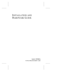
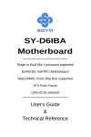
Figure 2-1 identifies the major ARO-1130SA components. You may
find it helpful to refer to this information while installing the
ARO-1130SA.
DIMM Memory Socket
Must be populated with a
168-pin EDO, 3.3v DIMM
LED Connector
Connects to the computer’s LED cable to
display activity on the SCSI bus
Bus Contacts
Inserted into the PCI/RAIDport I or II
expansion slot
Expansion Slot Bracket
Secures the ARO-1130SA
card inside your computer
BIOS EPROM
Provides booting
capabilities from a SCSI
hard disk or array
Figure 2-1. ARO-1130SA Major Components
2-2
Installing ARO-1130SA Hardware
Verifying Presence of DIMM Memory
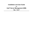
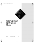
Before you can use the ARO-1130SA, the DIMM memory socket
must be populated with a DIMM, as shown in Figure 2-2. In most
cases, the ARO-1130SA comes pre-installed with a DIMM. Nevertheless, a 168-pin EDO 3.3v 60ns or faster DIMM can be used. (See
the Adaptec Web Site at http://www.adaptec.com/raid for a list of
approved DIMMs and vendors.)
168-pin DIMM
Figure 2-2. Installing a DIMM in the ARO-1130SA DIMM Memory Socket
2-3
ARO-1130SA Installation and Hardware Guide
Installing the ARO-1130SA
Follow these steps to install the ARO-1130SA:
Note: Before installing the ARO-1130SA in an existing server
that already has data, back up all data before continuing.
1
Turn OFF power to the computer, and disconnect the power cord.
2
Remove the cover from the computer case. (If necessary, refer
to the instructions in your computer documentation.)
3
Locate the PCI/RAIDport I or II expansion slot; unscrew and
remove the expansion slot bracket that covers the card-slot
opening.
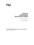
4
Insert the ARO-1130SA in the slot; press down firmly so that
the bus contacts are securely seated in the slot. Secure the
adapter bracket with the screw you removed in Step 3, as
shown in Figure 2-3.
Expansion Slot
Bracket Screw
ARO-1130SA Card Bracket
Bus Contacts
PCI Expansion Slots RAIDport I or II Expansion Slot
Figure 2-3. Installing the ARO-1130SA in a Typical PCI/RAIDport I or II Expansion Slot
2-4
Installing ARO-1130SA Hardware
Connecting the LED Cable to the ARO-1130SA
(Optional feature) An LED on the front panel of most computers
lights to indicate non-SCSI hard disk activity. If you would like that
LED to light whenever there is activity on SCSI Channel A (controlled by ARO-1130SA), disconnect the LED cable from the motherboard and connect it to the LED connector on the ARO-1130SA. If
the LED has a two-position cable, connect the cable to pins 1 and 2 of
the LED connector, as shown in Figure 2-4.
If the ARO-1130SA supports multiple SCSI channels, and you want
the LED to light whenever there is activity on any of those channels,
refer to your motherboard documentation for instructions on setting
the appropriate motherboard jumpers.
Note: If you are using non-SCSI disk drives (e.g., IDE), the
LED may no longer indicate activity on these drives when
you connect the LED cable to the ARO-1130SA.
LED Cable
1
1
2-pin LED Cable
1
LED Connector on
ARO-1130SA
Figure 2-4. Connecting the LED Activity Indicator Cable
2-5
ARO-1130SA Installation and Hardware Guide
Completing the Installation
Once the ARO-1130SA is installed in your server, refer to the documentation that came with your computer and SCSI devices for specific instructions on setting up your SCSI devices and connecting
them to the SCSI connectors on the motherboard.
Note: If you refer to the computer’s documentation for
installation instructions, be sure to return to this document
for instructions on running the Array1000xA BIOS & Driver
Selection Utility and installing the software included in the
package.
In most cases, it is not necessary to run the SCSISelect® utility.
Should you need to configure SCSI options (e.g., ID, Parity Checking, and Termination), see Appendix A, Configuring ARO-1130SA
with the SCSISelect Utility.
❒
2-6
▼ ▼ ▼ ▼
3
Using the Array1000xA
BIOS & Driver Selection
Utility
Whenever you install a new ARO-1130SA in your server and before
you run the Adaptec ArrayConfigSA program to create the first
array in your system, always run the Array1000xA BIOS & Driver
Selection Utility.
Caution: We highly recommend that you back up the data on
your array(s) before you use the Array1000xA BIOS & Driver
Selection Utility. This ensures that your data is completely
protected.
The Array1000xA BIOS & Driver Selection Utility installs the
ARO-1130SA BIOS by automatically updating (flashing) the correct
ARO-1130SA BIOS. The utility also determines which of the two
Manager Set driver diskettes (Disk A or Disk B) is required when
you install the operating system driver, as explained in Chapter 5
and Chapter 6.
3-1
ARO-1130SA Installation and Hardware Guide
Running the Array1000xA BIOS & Driver
Selection Utility
The Array1000xA BIOS & Driver Selection Utility is provided on a
bootable floppy disk and runs under DOS as a stand-alone utility. A
simple-to-use interface prompts you through the process. Follow
these steps to run the Array1000xA BIOS & Driver Selection Utility:
1
Insert the Array1000xA BIOS & Driver Selection Utility diskette in drive A and reboot your server. The utility starts
automatically and the initial Array1000xA BIOS & Driver
Selection Utility screen appears.
Note: The initial Array1000xA BIOS & Driver Selection
Utility screen identifies which of the two Manager Set
driver diskettes (Disk A or Disk B) are required when
you install the operating system driver, as explained in
Chapter 5 and Chapter 6. Make a note of which diskette
to use, and continue with Step 2.
2
Select either Express or Advanced setup.
Note: If you receive an “Unsupported Hardware Configuration,” message during setup, contact the system
manufacturer. The ARO-1130SA is not supported by
the system.
3-2
■
Express setup automatically updates the ARO-1130SA
BIOS. Select Express setup and the utility will do the rest.
When prompted, remove the floppy disk and press any key
to reboot the server. Continue with the Step 6.
■
Advanced setup also allows you to update the
ARO-1130SA BIOS. In addition, Advanced setup allows
you to select other options such as:
–
Display Current BIOS Checksum. Determines current
version of the ARO-1130SA BIOS.
–
Display New BIOS Checksum. Determines version of
the BIOS available on the floppy.
Using the Array1000xA BIOS & Driver Selection Utility
–
Save Current BIOS to a File. Saves the current
ARO-1130SA BIOS to a file.
–
Erase Current BIOS. Erases the current ARO-1130SA
BIOS.
To access these options, select Advanced setup and continue with Step 3.
3
From the Main Menu, select the array adapter card you want
to upgrade (only available array adapters can be selected). The
Utility Menu appears.
4
Make a selection from the Utility Menu.
5
Follow the instructions on the screen.
6
When prompted, remove the Array1000xA BIOS & Driver
Selection Utility diskette from drive A and reboot your server.
❒
3-3
▼ ▼ ▼ ▼
4
Creating the First Array
With the ArrayConfigSA
Utility
This chapter explains how to use the ArrayConfigSA Utility to create
the first bootable or non-bootable array on your server.
Before creating the array, make sure the disks for the array are connected and installed in your server (or array enclosure).
Note: ArrayConfigSA runs from a self-booting diskette. If
you are changing the configuration of a server that is
already in use on a network, log all users off the system and
shut it down in an orderly manner before you start
ArrayConfigSA.
Refer to the Adaptec CI/O Management Software User’s Guide for additional information.
4-1
ARO-1130SA Installation and Hardware Guide
Creating an Array
Follow these instructions to create the first array with
ArrayConfigSA:
1
Insert the ArrayConfigSA diskette in the server’s drive A and
reboot the server. ArrayConfigSA starts automatically.
2
3
Select Disk Array Operations from the Main Menu.
Select Create New Array from the Disk Array Operations
menu.
4
Type an array name and press Enter. The name can be up to 15
characters long and can include spaces and any other printable
characters.
5
Select an array type. Your options are
–
RAID 0: Data is striped across the disks in a RAID 0 array,
allowing for faster I/O performance than a single disk.
RAID 0 arrays do not store redundant data; if any disk in
the array fails, all data is lost.
–
RAID 1: Data is mirrored on one pair of disks. If one disk
fails, data is available. The actual data capacity of the array
equals half the available disk space.
–
RAID 5: The array contains redundant (parity) data distributed across all disks in the array. If any one disk fails,
data can be reconstructed from the parity information. If a
second disk fails before the array has been reconstructed,
all data is lost. The actual usable data capacity of the array
is equal to one less than the total number of disks. (One
disk’s worth of capacity is needed to hold the parity
information.)
–
RAID 0/1: Data is striped and mirrored on two or more
pairs of disks. If one disk in a pair fails, data is available.
The actual data capacity of the array equals half the total
available disk space.
See the Adaptec CI/O Management Software User’s Guide for more
information on selecting a RAID level.
4-2
Creating the First Array With the ArrayConfigSA Utility
6
Select the number of drives you want in the array and press
Enter. This number should not include spares (drives that automatically replace failed array drives). The number of drives
available for assignment is listed on the screen.
Note: This step does not apply to RAID 1 arrays, which
have two drives by definition.
7
Select array members. When the next screen appears, press Tab
to highlight a channel (if more than one SCSI channel is available). Select drives for the array by pressing the ↑ and ↓ keys
until the drive name is highlighted, and then press Ins or
Enter. The names of selected drives appear in the Adaptec
Array # box.
To select drives on a different channel press Tab to select
another channel and then select the drives from the SCSI IDs
on Channel menu. To deselect the drive you most recently
added, press Del.
Caution: A warning appears if you select a disk that
has partitions. Do not select a partitioned disk if it contains data you want to keep, because any existing data
will be erased when the disk becomes part of the array.
When you have selected the number of drives you specified in
step 6, the next screen appears automatically. If you are creating a RAID 1, RAID 0/1, or RAID 5 array, and if there are any
unassigned drives, the screen prompts you to define dedicated
spare drives for the array. (We recommend that you use a spare
pool instead of dedicated spares.)
Note: A spare must have at least the capacity of the
smallest drive in the array.
4-3
ARO-1130SA Installation and Hardware Guide
8
Select spares. If you do not want a spare, type n and continue
with Step 10. If you want to select dedicated spares, follow
these steps:
a At the prompt, type y.
b At the next prompt, type 1 or 2.
c Select one or two spares, using the same method you used
to select disks for the array.
9
Initialize array. When the Initialize Mode menu appears, select
Initialize Array to Zero. Formatting begins immediately. A
graph on the screen shows the progress of this operation.
Caution: If the drives contain data, all the data is lost
when you initialize the array.
Select Low-Level Format only if the drives were previously
formatted on another computer or if you think they may have
surface defects. Low-level formatting takes a long time for
large disk drives.
10
Select array block size. When the menu of block sizes appears,
select a block size. (This menu does not appear if the array is a
mirrored array with only two drives.)
The allowable block sizes are 8, 16, 32, 64 (the default), and
128 KBytes. The default block size gives the best overall
performance in most network server environments.
11
Wait for initialization to complete. When you see the message
Initialization of [array name] is complete, press any key to
return to the Disk Array Operations menu.
12
Create additional arrays. To create additional arrays (if disks
are available), return to Step 3. When all arrays are created, exit
ArrayConfigSA, remove the ArrayConfigSA diskette, and
reboot the server. After you reboot you can write data to the
arrays.
At this point, you can make your initial array bootable as
described in the next section.
4-4
Creating the First Array With the ArrayConfigSA Utility
Making the Array Bootable
You can make the array bootable so that the server boots from the
array instead of from a stand-alone (single) disk.
To make the array bootable, the array must be set to #0 in the boot
order. We recommend that you make your initial array bootable.
Follow these steps if you want the server to boot from the newly created array:
Note: The server will always attempt to boot from any
installed non-SCSI disks (for example, any IDE disk drive at
drive C). You must disable or remove all non-SCSI disks if
you want the server to boot from a SCSI disk or array.
1
Insert the ArrayConfigSA diskette in the server’s floppy disk
drive A.
2
Reboot the server from the diskette. ArrayConfigSA starts
automatically.
3
Select Display Boot Order from the Main Menu. The Boot
Order for Singles and Arrays window appears.
4
If the newly created array is at the top of the list, preceded by
the words Unit 0, no changes are necessary; if it has some other
unit number, highlight the array name and press Enter.
5
Use the arrow keys to move the selected array to the top of the
list. Then press Enter. If you want to change the boot order of
another array, select it, move it with the arrow keys, and press
Enter again.
6
Press Esc to return to the Main Menu.
7
Exit ArrayConfigSA, remove the diskette from drive A, and
reboot the server.
8
Prepare the array as you normally would prepare a boot disk
drive for your operating system. See either Chapter 5, Installing
Software on a Windows NT Server or Chapter 6, Installing Software on a Novell NetWare Server.
4-5
ARO-1130SA Installation and Hardware Guide
Note: You cannot use this procedure to change the boot
order of a SCSI disk drive that is not part of an array. If you
want to do this, create a one-disk RAID 0 array from the
disk. (Data is not actually striped on a one-disk array.)
❒
4-6
▼ ▼ ▼ ▼
5
Installing Software on a
Windows NT Server
This chapter explains how to install the software required to use the
ARO-1130SA in a system using Windows NT 4.0 Server.
Before installing the software, make sure the ARO-1130SA is already
installed. If you have not already done so, run the Array1000xA
BIOS & Driver Selection Utility (see Chapter 3) to determine which
of the two Manager Set driver diskettes (Disk A or Disk B) is
required to install the Window NT driver. If you plan to boot from
an array, make sure the array is already created. To install all of the
software, you must complete the following in the order presented:
■
Install the cda1000.sys driver for Windows NT
■
Install the Adaptec CI/O Management Software for Windows
NT
Once all software is installed, refer to the Adaptec CI/O Management
Software User’s Guide for instructions on adding, deleting, and managing your arrays.
Note: If your RAIDport I or II system has an additional
Adaptec AHA®-2940, AHA-3940, or any other AIC™-78x0
based host adapter installed (which is not associated with
the RAIDport), the driver for these adapters must be from
the Adaptec 7800 Family Manager Set 1.3 or later. Furthermore, if the Array1000xA BIOS & Driver Selection Utility
determines you require Disk B, refer to Appendix B.
5-1
ARO-1130SA Installation and Hardware Guide
Installing the Array1000xA Driver for Windows NT
This section explains how to install the Adaptec Array1000xA
Miniport Driver (cda1000.sys) for Windows NT. To begin driver
installation, see either Installing the Driver When Installing Windows
NT below, or Installing the Driver When Windows NT is Already
Installed on page 5-4.
Note: We recommend that you install your Windows NT
operating system on an array to take advantage of the
redundancy and performance features of the array.
Note: If your system: 1.) is RAIDport I or II equipped; AND 2.)
has an Adaptec AHA®-294x host adapter installed; AND 3.)
requires driver Disk B (as determined by the Array1000xA
BIOS & Driver Selection Utility), see Using the ARO-1130SA
with an AHA-294x, AHA-3940, or Other AIC-78x0 Based Host
Adapter and Driver Disk B (Windows NT Only) on page B-2 for
instructions on installing the Array1000CA Miniport Driver.
Installing the Driver When Installing Windows NT
To install the cda1000.sys driver when you are installing Windows
NT, follow these steps:
Note: If you have multiple arrays, we recommend temporarily powering off all devices except for the boot array
before installing Windows NT; otherwise, Windows NT limits the size of the partitions you can create to 1 GByte. When
Windows NT installation is complete, power on all devices
and reboot the system.
1
5-2
Start your system with the Windows NT Boot Diskette in the
floppy drive or the Windows NT Boot CD-ROM in the
CD-ROM drive.
Installing Software on a Windows NT Server
Note: To install Windows NT from a bootable
CD-ROM, make sure BIOS Support for Bootable
CD-ROM is enabled in SCSISelect.
2
Windows NT Boot diskette installation: When prompted, insert
diskette #2 in your floppy drive. After a few moments you will
see a blue screen. To setup Windows NT now, press Enter and
continue with Step 3 below.
Windows NT Boot CD-ROM installation: When the following
message appears onscreen, press the F6 key and skip to Step 4
below.
Setup is inspecting your computer system’s hardware…
3
4
5
Press S to skip autodetection of your SCSI host adapter.
Press S again to specify an additional device.
Press Enter to select Others; insert the Appropriate Adaptec
Array1000xA Family Manager Set driver diskette (Disk A or
Disk B) in your floppy disk drive and press Enter. (See Running the Array1000xA BIOS & Driver Selection Utility on page
3-2 to determine the appropriate driver diskette.)
6
The screen displays the adapter drivers supported on the
diskette. Select the Adaptec Array1000xA Family Adapter
driver and press Enter.
7
If you want to add drivers (other than for the ARO-1130SA), do
press S and repeat Step 5 for each additional adapter and
inserting the appropriate disk provided by the hardware manufacturer.
8
Press Enter to continue with the Windows NT operating
system setup. Follow the instructions onscreen and in the
Windows NT documentation to complete the installation.
5-3
ARO-1130SA Installation and Hardware Guide
Installing the Driver When Windows NT is Already Installed
To update or install the cda1000.sys driver if Windows NT is
already installed, follow these steps:
1
2
Start Windows NT.
3
4
5
6
7
Click the Control Panel.
Click the Start button on the Windows NT task bar, and then
point to Settings.
Double-click the SCSI Adapters icon.
Click the Drivers tab, and then click the Add button.
In the Install Driver window, click the Have Disk button.
Insert the Appropriate Adaptec Array1000xA Family Manager Set driver diskette (Disk A or Disk B) in your floppy
disk drive and press Enter; (See Running the Array1000xA
BIOS & Driver Selection Utility on page 3-2 to determine the
appropriate driver diskette.) Enter the following path to the
installation files and then click OK.
a:\winnt
The Adaptec Array1000xA Family Adapter driver is highlighted by default.
8
9
In the Install Driver window, Click OK.
Click the New button when asked if you want to use the currently installed driver(s) or install new one(s).
10
Type a:\winnt again, and click Continue. The driver is now
installed.
11
You must restart your computer for the changes to take effect.
Click Yes to restart your computer.
5-4
Installing Software on a Windows NT Server
Installing Adaptec CI/O Management Software
for Windows NT Server
Note: The Adaptec CI/O Management Software installation
process automatically installs both CI/O server and client
components on your Windows NT Server. Before you start
the Adaptec CI/O Management Software, be sure that communication with the server via the network is already established. (See the documentation provided with your TCP/IP
software for instructions on establishing communications,
and also Hints for Establishing Communications With Your
Server on page 7-3.)
Follow these steps to install the Adaptec CI/O Management Software for Windows NT:
1
Start Windows NT.
2
Insert the Adaptec CI/O Management Software CD-ROM in
your CD-ROM drive. If you are installing the software from
diskettes, insert Disk 1 of the Adaptec CI/O Management Software for Windows NT Server in the floppy disk drive.
3
Select Run from the File menu (Windows NT 4.0 users select
Start, and then Run), type the following and press Enter:
[pathname]setup.exe
(The setup.exe file is located at \win_nt\disk1\setup.exe on the
CD-ROM, and at \setup.exe on Disk 1 of the Adaptec CI/O
Management Software for Windows NT Server.)
4
Follow the directions that appear on the screen.
5
When installation is complete, reboot the system. The following NT Services start automatically in the background:
CIO Array Management Service
CIOArrayManager RPC Command
CIOArrayManager RPC EventP
CIOArrayManager RPC Event
NobleNet Portmapper
5-5
ARO-1130SA Installation and Hardware Guide
Note: These NT Services are configured to start automatically at boot time. After installation you can start
or stop these services through the Services icon in the
Windows NT Control Panel.
6
Double-click the Adaptec CI/O Management Software icon to
start the program.
See the Adaptec CI/O Management Software User’s Guide for information on using the Adaptec CI/O Management Software to add,
delete, or manage your arrays. If you are experiencing problems
starting the software, see Problems Running the Software On Your Windows NT Server on page C-2.
Note: You must have the proper level of Adaptec CI/O
Management Software password authorization if you want
to add and delete arrays and spares from a networked client. The default password is “adaptec.” See the Adaptec CI/O
Management Software User’s Guide for information on setting
security options.
❒
5-6
▼ ▼ ▼ ▼
6
Installing Software on a
Novell NetWare Server
This chapter explains how to install the software required to use the
ARO-1130SA in a Novell NetWare (NetWare 3.12 and 4.11) server.
Before installing the software, make sure the ARO-1130SA is already
installed. If you have not already done so, run the Array1000xA BIOS
& Driver Selection Utility (see Chapter 3) to determine which of the
two Manager Set driver diskettes (Disk A or Disk B) is required to
install the NetWare driver.If you plan to boot from an array, make
sure the array is already created. To install all of the software, you
must complete the following in the order presented:
■
Install the cda1000.dsk driver for Novell NetWare
■
Install the TIRPC Communications Module
■
Install the Adaptec CI/O Management Software for Novell
NetWare
Once all software is installed, refer to the Adaptec CI/O Management
Software User’s Guide for instructions on adding, deleting, and managing your arrays from the server console.
Note: If your RAIDport I or II system has an additional
Adaptec AHA-2940, AHA-3940, or any other AIC-78x0
based host adapter installed, the NetWare driver for these
adapters must be from the Adaptec 7800 Family Manager
Set 1.3 or later. Furthermore, if the Array1000xA BIOS &
Driver Selection Utility determines you require Disk B, refer
to Appendix B.
6-1
ARO-1130SA Installation and Hardware Guide
Installing the Array1000SA Driver for Novell
NetWare
This section explains how to install the Adaptec Array1000SA driver
(cda1000.dsk) for NetWare. To begin driver installation, see either
Installing the Driver When Installing NetWare below, or Installing the
Driver When NetWare is Already Installed on page 6-5.
Note: We recommend that you install your Novell NetWare
operating system on an array to take advantage of the
redundancy and performance features of the array.
Note: If your system: 1.) is RAIDport I or II equipped; AND
2.) has an Adaptec AHA-294x, AHA-3940, or any other
AIC-78x0 based host adapter installed; AND 3.) requires
driver Disk B (as determined by the Array1000xA BIOS &
Driver Selection Utility), see Appendix B, Using the
ARO-1130SA with Other Adaptec Products.
Installing the Driver When Installing NetWare
To install the cda1000.dsk driver when you are installing NetWare,
follow the instructions below for the version of NetWare you are
installing.
NetWare 4.11
Follow these instructions only if you are installing NetWare 4.11 for
the first time:
1
Follow the procedures in your NetWare documentation for
installing a new server. (For information on using a CD-ROM
drive on a NetWare server, see Appendix D, Using a CD-ROM
Drive in this installation guide.)
2
When a screen appears that asks you to select a disk driver,
press Enter.
3
Press Insert to install an unlisted driver.
6-2
Installing Software on a Novell NetWare Server
4
Insert the appropriate Adaptec Array1000xA Family Manager
Set driver diskette (Disk A or Disk B) into your floppy disk
drive. (See Running the Array1000xA BIOS & Driver Selection
Utility on page 3-2 to determine the appropriate driver
diskette.)
5
Press F3 and specify the path to the cda1000.dsk driver. For
NetWare 4.1, the driver is located in \netware\v4_1x on the
diskette.
6
Select cda1000.dsk and press Enter.
7
When prompted to save the current version of aspitran.dsk,
select Yes or No.
8
When prompted to save the current version of nwpaload.nlm,
select Yes or No.
9
When the message File “A:\netware\v4_1x\nwpaload.nlm was
not found…” appears, ignore the message and press Enter to
continue.
10
Select Continue copying the next file.
11
Select Yes to install an additional disk driver.
12
Select aspicd.dsk and press Enter.
13
When prompted to so save current version of aspicd.dsk, select
No.
14
When prompted to so save current version of aspicd.ddi, select
No.
15
Select No when prompted to install an additional disk driver.
16
Select Continue Installation.
17
Press Enter to continue.
18
Down and exit the server. At the DOS prompt, copy the
nwpa.nlm, nbi.nlm, and nwpaload.nlm files (located on the
Novell Installation CD-ROM) to the server’s startup directory
(usually c:\nwserver).
6-3
ARO-1130SA Installation and Hardware Guide
Note: To load the driver automatically at server bootup, make
sure the startup.ncf file includes the load command line for
the cda1000.dsk driver. (If you also have an Adaptec host
adapter that uses the Adaptec aic78xx.dsk driver, make sure
the driver loads after the cda1000.dsk driver.)
NetWare 3.12
Follow these instruction only if you are installing NetWare 3.12 for
the first time:
1
Follow the procedures in your NetWare documentation for
installing a new server. (For information on using a CD-ROM
drive on a NetWare server, see Appendix D, Using a CD-ROM
Drive.)
2
When you see the NetWare colon prompt (:), use the load command to install the driver from the appropriate Adaptec
Array1000xA Family Manager Set driver diskette (Disk A or
Disk B). (See Running the Array1000xA BIOS & Driver Selection
Utility on page 3-2 to determine the appropriate driver diskette.)
The correct syntax to load the cda1000.dsk driver is
:load [pathname]cda1000
(For example, :load a:\netware\v3_1x\cda1000)
Note: To load the drivers automatically at server bootup,
copy the aspitran.dsk and cda1000.dsk drivers to the
server’s startup directory and modify the startup.ncf so
that the proper path to the driver is specified.
The aspitran.dsk driver must reside in the same path as
cda1000.dsk, because NetWare attempts to load this file
automatically. If you also have an Adaptec host adapter
that uses the Adaptec aic78xx.dsk driver, make sure the
driver loads after the cda1000.dsk driver.
6-4
Installing Software on a Novell NetWare Server
3
Load the NetWare install program from the NetWare colon
prompt (:load install). Follow the instructions in the NetWare
documentation to complete the installation (e.g., creating disk
partitions, system volumes, etc.) of your server.
Installing the Driver When NetWare is Already Installed
To update or install the cda1000.dsk driver if NetWare is already
installed, follow the instructions in this section. The procedures are
similar for all versions of NetWare. Procedures that are specific to a
NetWare version are noted when necessary.
1
Copy the cda1000.dsk and aspitran.dsk files from the appropriate Adaptec Array1000SA Family Manager Set driver diskette (Disk A or Disk B) into the server’s startup directory (e.g.,
c:\nwserver, c:\server.312) on your hard disk drive. (See Running the Array1000xA BIOS & Driver Selection Utility on page
3-2 to determine the appropriate driver diskette.)
Note: For NetWare 3.12, the cda1000.dsk and
aspitran.dsk files are located in the \netware\v3_1x
subdirectory on the diskette; for NetWare 4.11, the files
are in \netware\v4_xx.
2
If necessary, modify the load command line in the startup.ncf
so that the proper path to the driver is specified. The correct
syntax to load the cda1000.dsk driver is
load [pathname ]cda1000
Note: If you unload cda1000.dsk driver, you must also
unload cioams.nlm. When you load cda1000.dsk driver
again, you must also load cioams.nlm. If cioams.nlm is not
unloaded when you unload cda1000.dsk, your system may
work erratically.
6-5
ARO-1130SA Installation and Hardware Guide
Installing the TIRPC Communications Module
The TIRPC communications module must be installed before you
install the Adaptec CI/O Management Software. The module allows
communications between the server and remote clients. Follow the
instructions below for the version of NetWare installed.
NetWare 3.12
1
Insert the Adaptec CI/O Management Software CD-ROM in
your CD-ROM drive. If you are installing the software from
diskettes, insert Disk 1 of the Adaptec CI/O Management Software for NetWare (TIRPC).
2
From the NetWare colon prompt (:), type the following and
press Enter:
load install
3
Select Product Options from the Installation Options Menu.
4
Press the <Ins> key.
5
Enter the path to the CD-ROM or Disk 1 (do not include the
backslash).
6
Select NetWare 3.x TIRPC Runtime and Configuration Files.
(TIRPC must be installed in the sys:system directory only.)
NetWare 4.11
1
Insert the Adaptec CI/O Management Software CD-ROM in
your CD-ROM drive. If you are installing the software from
diskettes, insert Disk 1 of the Adaptec CI/O Management Software for NetWare (TIRPC).
2
From the NetWare colon prompt (:), type the following and
press Enter:
load install
3
Select Product Options from the Installation Options Menu.
4
Select Install a Product Not Listed.
5
Press <F3> key.
6
Enter the path to the CD-ROM or Disk 1 (include the backslash).
6-6
Installing Software on a Novell NetWare Server
7
Select NetWare 4.0 TIRPC Runtime and Configuration Files.
(TIRPC must be installed in the sys:system directory only.)
Installing the Adaptec CI/O Management
Software for Novell NetWare
Note: Before you start the Adaptec CI/O Management Software, be sure that communication with the server via the
network is already established. (See the documentation provided with your TCP/IP software for instructions on establishing communications, and also Hints for Establishing
Communications With Your Server on page 7-3.)
Follow these steps to install the Adaptec CI/O Management Software for Novell NetWare:
1
Insert the Adaptec CI/O Management Software CD-ROM in
your CD-ROM drive. If you are installing the software from
diskettes, insert Disk 2 of the Adaptec CI/O Management Software for NetWare in the floppy disk drive.
2
From the NetWare colon prompt (:), type the following and
press Enter:
load [pathname]nwsetup
(The nwsetup NLM is located at \netware\disk2\nwsetup.nlm
on the CD-ROM, and at \nwsetup.nlm on Disk 2 of the Adaptec
CI/O Management Software for NetWare.)
Note: If you are using NetWare 3.12, you may receive a
Failed to allocate resources error message at this
point. This is because the CD-ROM (or floppy disk
drive) is not part of the default search path. If this happens, you must add the CD-ROM or floppy disk drive
to your search path by entering the following command before loading nwsetup:
search add [pathname]
6-7
ARO-1130SA Installation and Hardware Guide
3
From the NWSETUP Installation menu, select Default
Installation or Custom Installation (press F1 for help).
4
At the end of the installation process, select Yes when you are
prompted to update the autoexec.ncf file. (This adds the
appropriate NLM command lines to the file so that all software
is automatically loaded when the server starts.)
See the Adaptec CI/O Management Software User’s Guide for information on using the Adaptec CI/O Management Software to add,
delete, or manage your arrays from your server console.
Adaptec CI/O Management Software Installation Hints
■
For communications supported over TCP/IP, the tcpip.nlm
must be loaded and the IP protocol must be bound to a valid IP
address. The IP protocol generally needs to be bound to an ethernet frame type, ETHERNET_II, which must be specified
when loading the LAN driver. A LAN driver can be loaded
multiple times for different ethernet frame types.
■
Command lines similar to the following are automatically
added to the autoexec.ncf file when you run the nwsetup
utility:
#
# NWSETUP LAST UPDATE XX-XX-XX
#
RPCSTART
IOMGR.NCF
IOMGRSRV.NCF
IOMGRRPC.NCF
❒
6-8
▼ ▼ ▼ ▼
7
Installing Software on a
Remote Client
This chapter explains how to install the Adaptec CI/O Management
Software on a remote network client running under Windows (Windows 3.1x, Windows® 95, and Windows NT). If you want the capability to manage your arrays on the server from a remote networked
client, continue with the remainder of this chapter. Once installed,
refer to the Adaptec CI/O Management Software User’s Guide for
instructions on using the software.
7-1
ARO-1130SA Installation and Hardware Guide
Installing Adaptec CI/O Management Software
Follow these steps to install the software:
Note: Before you start the Adaptec CI/O Management Software, be sure that communication with the server via the network is already established. As long as communication is
established, it is not a requirement to log-on to the server to
install the software and to monitor the server via the network.
(See the documentation provided with your TCP/IP or SPX/
IPX software for instructions on establishing communications, and also Hints for Establishing Communications With Your
Server on page 7-3.)
1
Start Windows on the client.
2
Insert the Adaptec CI/O Management Software CD-ROM in
your CD-ROM drive. If you are installing the software from
diskettes, insert Disk 1 of the Adaptec CI/O Management Software for Windows 95 and Windows NT Clients.
3
Select Run from the File menu (Windows 95 and NT users
select Start, and then Run), type the following and press Enter.
[pathname]setup.exe
(The setup.exe file is located in \win_client\disk1\setup.exe on
the CD-ROM, and in \setup.exe on Disk 1 of the Adaptec CI/O
Management Software for Windows 95, and Windows NT
Clients.)
4
Follow the directions that appear on the screen.
During installation you will be prompted to enter the host name
of the client PC. If you do not know the host name, you can add
the information later by inserting a line in the autoexec.bat file.
Instructions for this step appear on the screen during installation.
See the Adaptec CI/O Management Software User’s Guide for information on using the Adaptec CI/O Management Software to add,
delete, or manage your arrays from the remote client.
7-2
Installing Software on a Remote Client
Note: You must have the proper level of Adaptec CI/O
Management Software password authorization if you want
to add and delete arrays and spares from a networked client. The default password is “adaptec.” See the Adaptec CI/O
Management Software User’s Guide for information on setting
security options.
Hints for Establishing Communications With Your Server
Communication with the server via the network must be established
prior to installing the Adaptec CI/O Management Software on a
networked client. The following information is provided to help you
set up proper communication:
TCP/IP Networks
■
When installing your TCP/IP software (not provided by
Adaptec), follow the installation instructions provided with
your TCP/IP software. You will be asked to enter information
such as IP address, host name, host file, etc.
■
The TCP/IP stack uses the host name from TCP/IP setup.
SPX/IPX Networks
■
On an SPX/IPX network, make sure to install the NetWare
Client Software for Windows (provided by Microsoft). During
installation, certain DLLs required by the Adaptec CI/O Management Software are installed.
■
The host name is identified through the SET RPCHOST=
environment variable. You can enter this variable through the
setup process, or you can manually add it to the autoexec.bat
file.
Note: Under dual stack situations, we recommend using the
same host name for both TCP/IP and SPX/IPX to minimize
any naming confusion.
❒
7-3
▼ ▼ ▼ ▼
A
Configuring ARO-1130SA
with the SCSISelect Utility
The SCSISelect configuration utility allows you to change SCSI settings without opening the server chassis or handling the card.
SCSISelect also contains utilities that allow you to low-level format
or verify the disk media of your SCSI hard disk drives.
The SCSISelect settings are listed in the table below. If you want to
view and/or change the current settings, or if you would like to format or verify a disk, see Starting the SCSISelect Utility on page A-2.
Detailed descriptions of each setting begin on page A-4.
SCSI Bus Interface Definitions
Host Adapter SCSI ID
SCSI Parity Checking
Host Adapter SCSI Termination
Host Adapter UltraSCSI
SCSI Device Configuration
Initiate Sync Negotiation
Maximum Transfer Rate
Enable Disconnection
Initiate Wide Negotiation1
Send Start Unit Command
Include in BIOS Scan
Additional Options
Array1000xA BIOS
BIOS Support for Bootable CD-ROM
1
This option is available only if Wide SCSI is supported on the motherboard.
A-1
ARO-1130SA Installation and Hardware Guide
Starting the SCSISelect Utility
To start SCSISelect, press Ctrl-A when the following prompt appears
when you turn on or reboot your server:
Press <Ctrl><A> for SCSISelect (TM) Utility!
The menu that appears displays the options Configure/View Host
Adapter Settings and SCSI Disk Utilities, as shown in Figure 7-1.
Adaptec Array1000xA Family
SCSISelect(TM)
Utility
Adaptec Array1000xA Family at Bus:Channel 00:C
Would you like to configure the PCI device, or run the
SCSI disk utilities? Select the option and press <Enter>.
Press <F5> to switch between color and monochrome modes.
Options
Configure/View Host Adapter Settings
SCSI Disk Utilities
Arrow keys to move cursor, <Enter> to select option, <Esc> to exit ( * =default)
Figure 7-1. SCSISelect Menu
Using SCSISelect Menus
To select a SCSISelect menu option, move the cursor to the option
with the ↑ and ↓ keys, then press Enter. In some cases, selecting an
option displays another menu. You can return to the previous menu
at any time by pressing Esc.
To restore the original SCSISelect default values, press F6 from the
Configure/View Host Adapter Settings screen. To toggle the display
between color and monochrome modes, press F5 from the main
SCSISelect screen (this feature does not work on some monitors).
A-2
Configuring ARO-1130SA with the SCSISelect Utility
Exiting SCSISelect
To exit SCSISelect, press Esc until a message prompts you to exit (if
you changed any host adapter settings, you are prompted to save
the changes before you exit). Select Yes to exit, then press any key to
reboot the workstation. Any changes you made in SCSISelect take
effect after the server boots.
Using the SCSI Disk Utilities
To access the SCSI disk utilities, select the SCSI Disk Utilities
option from the menu that appears after starting SCSISelect. Once
the option is selected, SCSISelect immediately scans the SCSI bus (to
determine the devices installed) and displays a list of all SCSI IDs
and the devices assigned to each ID.
When you select a specific ID and device, a small menu appears, displaying the options Format Disk and Verify Disk Media.
■
Format Disk—This utility allows you to perform a low-level
format on a hard disk drive. Each hard disk drive must be lowlevel formatted before you can use your operating system’s
partitioning and file preparation utilities, such as MS-DOS
Fdisk and Format.
Most SCSI disk devices are preformatted at the factory and do
not need to be formatted again. The Adaptec Format Disk utility is compatible with the vast majority of SCSI disk drives.
Caution: A low-level format destroys all data on the
drive. Be sure to back up your data before performing
this operation. You cannot abort a low-level format
once it is started.
■
Verify Disk Media—This utility allows you to scan the media
of a hard disk drive for defects. If the utility finds bad blocks
on the media, it prompts you to reassign them; if you select yes,
those blocks are longer used. You can press Esc at any time to
abort the utility.
A-3
ARO-1130SA Installation and Hardware Guide
SCSISelect Settings
SCSI Bus Interface Definitions
The following settings are the SCSISelect settings most likely to
require any modification.
■
Host Adapter SCSI ID— This option sets the ARO-1130SA’s
SCSI ID. We recommend that you leave the ARO-1130SA set to
SCSI ID 7, which gives the ARO-1130SA the highest priority on
the SCSI bus.
■
SCSI Parity Checking—This option determines whether the
ARO-1130SA verifies the accuracy of data transfer on the SCSI
bus. You should disable SCSI Parity Checking on the
ARO-1130SA and all SCSI devices if any SCSI device supported by the ARO-1130SA does not support SCSI parity; otherwise, leave it enabled. Most SCSI devices do support SCSI
parity. If you are not sure whether a device supports SCSI parity, consult the documentation for the device.
■
Host Adapter SCSI Termination—This option is used in conjunction with your motherboard termination settings. Refer to
your motherboard documentation for instructions on properly
setting termination.
■
Host Adapter UltraSCSI —This option determines whether
the ARO-1130SA supports Ultra SCSI data transfer speeds. If
you have any Ultra SCSI devices installed, you should enable
this setting. When this setting is enabled, the ARO-1130SA
negotiates for data transfer speeds of up to 20 MBytes/sec (40
MBytes/sec for Wide SCSI devices).
Note: If you use Ultra SCSI data transfer speeds, be
sure to use high-quality cables to connect the disk
drives supported by the ARO-1130SA. The quality of
the cable is much more critical when you use higherspeed data transfer.
A-4
Configuring ARO-1130SA with the SCSISelect Utility
SCSI Device Configuration
The SCSI device settings allow you to configure certain parameters
for each device on the SCSI bus. To configure settings for a specific
device, you must know the SCSI ID assigned to that device. If you are
not sure of the SCSI ID, see Using the SCSI Disk Utilities on page A-3.
■
Initiate Sync Negotiation—This option determines whether
synchronous data transfer negotiation (Sync Negotiation)
between the device and SCSI channel is initiated by the SCSI
channel. Normally, you should leave Initiate Sync Negotiation
set to Enabled, because most SCSI devices support synchronous
negotiation and because it allows for faster data transfer.
■
Maximum Transfer Rate—This option determines the maximum data transfer rate that the SCSI channel supports. The
effective data transfer rate is doubled when Initiate Wide
Negotiation is set to Yes. For example, a transfer rate of
20 MBytes/sec becomes 40 MBytes/sec.
■
Enable Disconnection—This option determines whether the
SCSI channel allows the SCSI device to disconnect from the
SCSI bus (sometimes called Disconnect/Reconnect). This
option should be enabled for maximum performance.
■
Initiate Wide Negotiation—This option determines whether
the SCSI channel attempts 16-bit data transfer instead of 8-bit
data transfer. The effective data transfer rate is doubled when
16-bit data transfer is used. For example, a transfer rate of
10 MBytes/sec becomes 20 MBytes/sec. If you have a Wide
SCSI device, make sure this option is enabled.
■
Send Start Unit Command—This option determines whether
the Start Unit Command is sent to the SCSI device at bootup
(most devices do not require this).
■
Include in BIOS Scan—This option determines whether the
Array1000xA BIOS supports hard disk drives attached to the
SCSI channel. When set to Yes, the ARO-1130SA BIOS controls
the hard disk drive. When set to No, the ARO-1130SA BIOS
does not control the hard disk drive.
A-5
ARO-1130SA Installation and Hardware Guide
Additional Options
Array1000xA BIOS
This option determines whether the ARO-1130SA BIOS is installed
at boot time. When set to Enabled, the ARO-1130SA BIOS is installed
and all Int13 (except bootable CD-ROM) devices are supported.
When set to Disabled, the ARO-1130SA BIOS is not installed.
BIOS Support for Bootable CD-ROM
This option determines whether the Array1000xA BIOS supports
booting from a CD-ROM drive. When set to Enabled, the
ARO-1130SA allows booting from a CD-ROM drive.
❒
A-6
▼ ▼ ▼ ▼
B
Using the ARO-1130SA with
Other Adaptec Products
You cannot install more than one ARO-1130SA card in the same
system; however, you can install an ARO-1130SA in servers that
have other PCI-, ISA-, or EISA-based host adapters installed. When
installing multiple adapters, consider the following:
■
Adaptec AAA-130xx Series adapters cannot coexist with an
ARO-1130SA inside a RAIDport I or II equipped system.
■
All drives in a single array must be connected to the same host
adapter. A single array cannot be created with drives from two
or more host adapters.
■
If you are booting from a SCSI disk drive or array supported
by the ARO-1130SA, then the ARO-1130SA must be the card
that the server scans first. Some computers boot from the device
with the lowest PCI device number; others boot from the device
with the highest number. (See also Making the Array Bootable on
page 4-5.) You can disable the BIOS on cards that are scanned
before the desired boot card.
■
In systems with EISA- and ISA-based host adapters, the boot
host adapter must have the lowest BIOS base address. The system
BIOS automatically controls the ARO-1130SA base address (the
user has no control over the assigned address).
B-1
ARO-1130SA Installation and Hardware Guide
Using Driver Disk B
If the Array1000xA BIOS & Driver Selection Utility determines you
require Disk A of the manager set driver diskettes, the rest of this
appendix does not apply. If Disk B is required, then note the following for these Adaptec products:
■
AHA-294x, AHA-3940, or any other AIC-78x0 based host
adapter: These host adapters can coexist with an ARO-1130SA
inside a RAIDport I or II system using Windows NT or
NetWare. In Windows NT, however, it is necessary to make
some modification to your Windows NT configuration. See
Using the ARO-1130SA with an AHA-294x, AHA-3940, or Other
AIC-78x0 Based Host Adapter and Driver Disk B (Windows NT
Only) below.
■
AHA-3940AU/3940AUW: Due to a PCI ID conflict with the
hardware on the motherboard that requires driver Disk B,
these host adapters cannot coexist with an ARO-1130SA inside
a RAIDport I or II system.
Using the ARO-1130SA with an AHA-294x,
AHA-3940, or Other AIC-78x0 Based Host
Adapter and Driver Disk B (Windows NT Only)
This section offers two scenarios for using the ARO-1130SA in a system also containing any of the above host adapters. If the
Array1000xA BIOS & Driver Selection Utility (see Chapter 3) determines you require Disk B of the manager set driver diskettes, follow
the scenario below that matches your situation. You will need to
install drivers and make changes to the Windows NT Registry.
If the Array1000xA BIOS & Driver Selection Utility determines you
require Disk A, this section does not apply. To install the driver, follow the instructions in Installing the Array1000xA Driver for Windows
NT on page 5-2.
Caution: We recommend that you do not attempt to change
the Windows NT Registry unless you are an experienced
computer user.
B-2
Using the ARO-1130SA with Other Adaptec Products
Scenario #1: Adding an ARO-1130SA to a RAIDport I or II
System with an AHA-294x, AHA-3940, or Other AIC-78x0
Based Host Adapter
These instructions assume that Windows NT is already installed on
the server and that the boot drive is currently connected to an
AHA-294x, AHA-3940, or any other AIC-78x0 based host adapter. If
the ARO-1130SA is already installed, shut down the server, remove
the ARO-1130SA from the expansion slot, and restart the server.
Installing the ARO-1130SA Driver
1
Start the Windows NT Control Panel and double click the
SCSI Adapters icon.
2
Click the Drivers tab and click Add.
3
Click Have Disk …, and insert Disk B of the Array1000xA
Family Manager Set diskettes in the floppy disk drive. (This
diskette is included with your ARO-1130SA adapter.)
4
When the Install from Disk dialog box appears, type a:\winnt
on the command line and click OK.
5
Select Adaptec Array1000xA Family Adapter and click OK.
6
When a message appears asking you if you want to restart
Windows NT, click No.
7
Exit from Control Panel.
Changing Registry Settings
1
Back up the NT Registry, using one of the techniques described
in Backing up the Windows NT Registry on page B-10
Caution: It is very important to back up the NT Registry before you make any changes to it. This allows you
to restore the original NT Registry settings if there is a
problem with the new configuration.
2
Run the Registry Editor (regedit.exe).
B-3
ARO-1130SA Installation and Hardware Guide
3
When the Registry Editor window appears, expand the tree on
the left until you can see the nodes under
\HKEY_LOCAL_MACHINE\System\CurrentControlSet\Services.
4
Select cda1000 on the left part of the screen. Write down the
cda1000 Tag value that appears on the right part of the screen.
The Tag value is a hex number followed by an equivalent decimal equivalent in brackets: for example, 0x00000002 [2].
5
Select aic78xx on the left part of the screen. Write down the
aic78xx Tag value that appears on the right part of the screen.
6
Expand the tree on the left until you can see the nodes under
\HKEY_LOCAL_MACHINE\System\CurrentControlSet\Control\GroupOrderList.
7
Select GroupOrderList.
8
Click the right mouse button on SCSI Miniport on the right
side of the window and select Modify from the popup menu.
A table appears with columns of two- and four-number
groups, something like this:
0005
0010
0015
0020
etc.
02
01
04
06
00
00
00
00
00
00
00
00
00
00
00
00
03
01
05
07
00
01
00
00
00
00
00
00
00
00
00
00
This table of hexidecimal numbers indicates the Tag-value
sequence in which the SCSI Miniport drivers are loaded when
you start Windows NT.
9
Determine what the Tag value loading sequence is. Here is
how you do this:
a Ignore the four-digit groups on the left of each row.
b Going from left to right, and starting on the first row,
divide the two-digit numbers into groups of eight. In this
example, the groups are
02 00 00 00
03 00 00 00
01 00 00 00
B-4
Using the ARO-1130SA with Other Adaptec Products
01 01 00 00
etc.
You need to write down all the number groups from all
rows in the table.
c In each group of eight numbers, reverse the sequence of the
two-digit pairs, like this:
00 00
00 00
00 00
00 00
etc.
00
00
00
01
02
03
01
01
d Write down the series of resulting numbers, without all the
extra zeroes. In this example, it is 2, 3, 1, 101, etc. This is the
Tag value loading sequence for SCSI Miniport drivers. In
other words, when Windows NT loads these miniport
drivers, the one with Tag value 2 is loaded first, then the
one with Tag value 3, and so on.
10
Compare the Tag value loading sequence to the actual tag values of cda1000 and aic78xx that you determined in steps 4
and 5. If cda1000 is loading before aic78xx, skip to step 16. If
aic78xx is loading first, continue with the next step.
11
Expand the tree on the left until you can see the nodes under
\HKEY_LOCAL_MACHINE\System\CurrentControlSet\Services.
12
Select cda1000 on the left part of the screen. Click the right
mouse button on Tag Value on the right part of the screen and
select Modify from the popup menu.
13
Type the tag value of the aic78xx miniport driver in the space
provided and click OK.
14
Select aic78xx on the left part of the screen. Click the right
mouse button on Tag Value on the right part of the screen and
select Modify from the popup menu.
15
Type the tag value of the cda1000 miniport driver in the space
provided and click OK. You have now reversed the tag values
for the two miniport drivers, and the cda1000 driver will load
first.
B-5
ARO-1130SA Installation and Hardware Guide
16
Exit from the Registry Editor and from Windows NT. Then
shut down the server.
17
Physically install the ARO-1130SA in the PCI/RAIDport
expansion slot.
18
Attach your boot drive to one of the SCSI channels controlled
by the ARO-1130SA and boot the server.
Scenario #2: Adding an AHA-294x, AHA-3940, or Other
AIC-78x0 Based Host Adapter to a RAIDport I or II System
with an ARO-1130SA
These instructions assume that Windows NT is already installed on
the server and that the boot drive is connected to the SCSI channel
controlled by the ARO-1130SA. If the AHA-294x, AHA-3940, or any
other AIC-78x0 based host adapter is already installed, shut down
the server, remove the adapter from the slot, and restart the system.
Installing the AHA-2940, AHA-3940, or AIC-78x0 Family Driver
1
Start the Windows NT Control Panel and double click the
SCSI Adapters icon.
2
Click the Drivers tab and click Add.
3
Click Have Disk …, and insert AIC-78xx Family Manager Set
diskette in the floppy disk drive. (This diskette was included
with your 2940 Family adapter.)
4
When the Install From Disk dialog box appears, type
a:\winnt\4_0 on the command line and click OK.
5
Select Adaptec AHA290x/291x/394x/494x/4944/AIC78xx PCI
SCSI Controller (NT 4.0) and click OK.
6
When a message appears asking if you want to restart
Windows NT, click No.
7
Exit from Control Panel.
B-6
Using the ARO-1130SA with Other Adaptec Products
Changing Registry Settings
1
Back up the NT Registry, using one of the techniques described
in Backing up the Windows NT Registry on page B-10
Caution: It is very important to back up the NT Registry before you make any changes to it. This allows you
to restore the original NT Registry settings if there is a
problem with the new configuration.
2
Run the Registry Editor (regedit.exe).
3
When the Registry Editor window appears, expand the tree on
the left until you can see the nodes under
\HKEY_LOCAL_MACHINE\System\CurrentControlSet\Services.
4
Select cda1000 on the left part of the screen. Write down the
cda1000 Tag value that appears on the right part of the screen.
The Tag value is a hex number followed by an equivalent decimal equivalent in brackets: for example, 0x00000002 [2].
5
Select aic78xx on the left part of the screen. Write down the
aic78xx Tag value that appears on the right part of the screen.
6
Expand the tree on the left until you can see the nodes under
\HKEY_LOCAL_MACHINE\System\CurrentControlSet\Control\GroupOrderList.
7
Select GroupOrderList.
B-7
ARO-1130SA Installation and Hardware Guide
8
Click the right mouse button on SCSI Miniport on the right
side of the window and select Modify from the popup menu.
A table appears with columns of two- and four-number
groups, something like this:
0005
0010
0015
0020
etc.
02
01
04
06
00
00
00
00
00
00
00
00
00
00
00
00
03
01
05
07
00
01
00
00
00
00
00
00
00
00
00
00
This table of hexidecimal numbers indicates the Tag-value
sequence in which the SCSI Miniport drivers are loaded when
you start Windows NT.
9
Determine what the Tag value loading sequence is. Here is
how you do this:
a Ignore the four-digit groups on the left of each row.
b Going from left to right, and starting on the first row,
divide the two-digit numbers into groups of eight. In this
example, the groups are
02 00
03 00
01 00
01 01
etc.
00
00
00
00
00
00
00
00
You need to write down all the number groups in all rows
of the table.
c In each group of eight numbers, reverse the sequence of the
two-digit pairs, like this:
00 00
00 00
00 00
00 00
etc.
B-8
00
00
00
01
02
03
01
01
Using the ARO-1130SA with Other Adaptec Products
d Write down the series of resulting numbers, without all the
extra zeroes. In this example, it is 2, 3, 1, 101, etc. This is the
Tag value loading sequence for SCSI Miniport drivers. In
other words, when Windows NT loads these miniport
drivers, the one with Tag value 2 is loaded first, then the
one with Tag value 3, and so on.
10
Compare the Tag value loading sequence to the actual tag values of cda1000 and aic78xx that you determined in steps 4 and
5. If cda1000 is loading before aic78xx, skip to step 16. If
aic78xx is loading first, continue with the next step.
11
Expand the tree on the left until you can see the nodes under
\HKEY_LOCAL_MACHINE\System\CurrentControlSet\Services.
12
Select cda1000 on the left part of the screen. Click the right
mouse button on Tag Value on the right part of the screen and
select Modify from the popup menu.
13
Type the tag value of the aic78xx miniport driver in the space
provided and click OK.
14
Select aic78xx on the left part of the screen. Click the right
mouse button on Tag Value on the right part of the screen and
select Modify from the popup menu.
15
Type the tag value of the cda1000 miniport driver in the space
provided and click OK. You have now reversed the tag values
for the two miniport drivers, and the cda1000 driver will load
first.
16
Exit from the Registry Editor and from Windows NT. Then
shut down the server.
17
Physically install the AHA-2940 Family adapter in the expansion slot.
18
Boot the server.
B-9
ARO-1130SA Installation and Hardware Guide
Backing up the Windows NT Registry
It is very important to back up the Windows NT Registry before
making any changes to it. This will allow you to recover if the
changes make your system unusable. Here are two ways to back up
the Windows NT Registry. The backup utilities described here are
included with NT Workstation:
■
Use the ntbackup utility to create a tape copy of all data files
and Registry information. Be sure to select the Backup Local
Registry option when performing the backup.
■
Run the rdisk utility with the /s option to create a copy of the
Registry on a hard disk. (A typical backup file is 5 MBytes to
10 MBytes in size.) Then use xcopy or some other command to
copy the information to removable media. You must have the
three NT boot floppy disks to restore an RDISK-saved registry
to your workstation.
❒
B-10
▼ ▼ ▼ ▼
C
Troubleshooting
Troubleshooting Checklist
Check the following if you have problems installing or running the
ARO-1130SA and SCSI devices:
■
Does the ARO-1130SA BIOS sign-on message appear during
bootup? If not, check the following items:
–
Is the ARO-1130SA properly seated in a PCI/RAIDport
expansion slot? Refer to your computer documentation for
the slot location.
–
Does your computer CMOS setup require you to enable
PCI bus parameters (see your computer documentation)? If
so, run the CMOS Setup program and assign the parameters—usually IRQ, Enable PCI Slot, and Enable Master.
–
Have you run the Array1000xA BIOS & Driver Selection
Utility?
■
Is the SCSI bus terminated properly, and are all SCSI devices
turned on?
■
Are all SCSI bus cables and power cables connected?
■
Does each channel and each device on the channel have a
unique SCSI ID?
■
If you are having trouble booting from a SCSI disk drive or
array, make sure your computer’s CMOS setup is set to No
Drives Installed (the required setting for SCSI drives). Also,
verify that the drive or array has been selected as the boot-first
(boot) device and that the boot partition is active.
C-1
ARO-1130SA Installation and Hardware Guide
Problems Running the Software On Your
Windows NT Server
If the Adaptec CI/O Management Software does not start when you
double-click the program icon and you see a warning box with
Unable to Initialize IOMAPI, try the following:
■
Verify that the following NT services have a status of Started
(double-click the Services icon in Control Panel). If they do
not, select each service and press the Start button:
CIO Array Management Service
CIOArrayManager RPC Command
CIOArrayManager RPC EventP
CIOArrayManager RPC Event
NobleNet Portmapper
■
Make sure you have the proper security access rights to the
Windows NT Services. The Windows NT Services can be
started, stopped, paused, etc., by different users (administrators, power users, local users, etc.) according to the NT service
security rules defined by Microsoft (refer to the Windows NT
documentation for more details).
■
Verify that the Registry was updated correctly during installation. If the values do not match the values listed below, try
reinstalling the Adaptec CI/O Management Software:
–
The correct entries for HKEY_LOCAL_MACHINE\
SYSTEM\CurrentControlSet\Services\
CIOArrayManagement are:
DisplayName: REG_SZ: CIO Array Management
Service (v x.xx)
ErrorControl: REG_DWORD: 0x01
ImagePath: REG_SZ: [Pathname specified during
installation]iomgr.exe
ObjectName: REG_SZ: LocalSystem
Start: REG_DWORD: 0x02
Type: REG_DWORD: 0x110
SharedMemName: REG_SZ: iomgr.shm
C-2
Troubleshooting
–
The correct entries for HKEY_LOCAL_MACHINE\
SYSTEM\CurrentControlSet\Services\EventLog\System\
CIOArrayManagement are:
EventMessageFile: REG_SZ: [pathname to system32
directory]\system32\iomgrmsg.dll
TypesSupported: REG_DWORD: 0x7
–
The correct entries for HKEY_LOCAL_MACHINE\
SYSTEM\CurrentControlSet\Services\
NobleNetPortmapper are:
DisplayName: REG_SZ: NobleNet Portmapper
ErrorConrol: REG_DWORD: 0x1
ImagePath: REG_EXPAND_SZ: Absolute Path of
“portserv.exe”
ObjectName: REG_SZ : LocalSystem
Start: REG_DWORD : 0x02
Type: REG_DWORD : 0x10
–
The correct entries for HKEY_LOCAL_MACHINE\
SYSTEM\CurrentControlSet\Services\
CIOArrayManager RPC Command are:
DependOnService: REG_MULTI_SZ: NobleNet
Portmapper CIOArrayManagement
DisplayName: REG_SZ: CIOArrayManager RPC
Command
ErrorControl: REG_DWORD: 0x1
ImagePath: REG_EXPAND_SZ: Absolute Path of
“iomrpccm.exe”
ObjectName: REG_SZ : LocalSystem
Start: REG_DWORD : 0x02
Type: REG_DWORD : 0x10
C-3
ARO-1130SA Installation and Hardware Guide
–
The correct entries for HKEY_LOCAL_MACHINE\
SYSTEM\CurrentControlSet\Services\
CIOArrayManager RPC Event are:
DependOnService: REG_MULTI_SZ: CIOArrayManagement CIOArrayManager RPC Command
DisplayName:REG_SZ: CIOArrayManager RPC Event
ErrorControl: REG_DWORD: 0x1
ImagePath: REG_EXPAND_SZ: Absolute Path of
“iomrpcev.exe”
ObjectName: REG_SZ : LocalSystem
Start: REG_DWORD : 0x02
Type: REG_DWORD : 0x10
Problems Running SNMP Agent on Your
Windows NT Server
If you have problems running SNMP agent, try the following:
■
Make sure you configure Windows NT base SNMP support,
including the appropriate trap community name and trap destinations. The SNMP configuration is accessed via Control
Panel/Network/SNMP Service. If the SNMP service does not
appear as a configurable item, then SNMP support must be
installed from the Windows NT distribution media.
■
Verify that the values in the Registry match the values listed
below:
–
Make sure HKEY_LOCAL_MACHINE\SYSTEM\CurrentControlSet\Services\SNMP\Parameter\ExtensionAgents
includes an entry like this:
3 REG_SZ SOFTWARE\Adaptec\CIOSNMP\
CurrentVersion
(where 3 should be replaced by the next unused number)
C-4
Troubleshooting
–
Make sure HKEY_LOCAL_MACHINE\SOFTWARE\Adpatec\CIOSNMP\CurrentVersion includes a value
like this:
Pathname: REG_SZ: [installationpath]\ciosnmp.dll
For example, if the recommended c:\ciodata path is used
for the installation directory, then the Pathname value
would look like:
Pathname: REG_SZ: c:\ciodata\ciosnmp.dll
–
Make sure HKEY_LOCAL_MACHINE\SYSTEM\CurrentControlSet\Services\SNMP includes an entry like this:
DependOnService: REG_MULTI_SZ: CIOArrayManagement
❒
C-5
▼ ▼ ▼ ▼
D
Using a CD-ROM Drive
Should you need to install a CD-ROM, the Array1000xA Family
Manager Set drivers diskette included with the ARO-1130SA contains the DOS and NetWare driver software you need in order to use
a CD-ROM controlled by the ARO-1130SA. This appendix explains
how to set up your CD-ROM drive so that you can initially install
your software.
Using a CD-ROM Drive with DOS
To operate a CD-ROM drive supported by the ARO-1130SA under
DOS, you need
■
The SCSI driver, aspi8dos.sys (version 1.32 or later)
■
The CD-ROM driver, aspicd.sys
■
The Microsoft CD-ROM extensions, mscdex.exe
The aspi8dos.sys and aspicd.sys files must be copied from the \dos
directory on the Adaptec Array 1000xA Family Manager Set driver
diskette to a directory (e.g., c:\scsi) on your hard disk drive. The
mscdex.exe file is included with MS-DOS 6.x and above (see your
MS-DOS documentation for details).
Note: If you use MS-DOS 5 and do not have mscdex.exe, we
recommend that you upgrade to MS-DOS 6 or above. You
can also obtain mscdex.exe from Microsoft’s online bulletin
board or the CompuServe forum.
D-1
ARO-1130SA Installation and Hardware Guide
To complete the driver installation, edit the config.sys file to include
command lines for aspi8dos.sys and aspicd.sys, and edit the
autoexec.bat file to include a command line for mscdex.exe. The following examples illustrate the command line format and the command options appropriate for most systems.
■
Sample command lines for config.sys file:
device=c:\scsi\aspi8dos.sys /d
device=c:\scsi\aspicd.sys /d:aspicd0
■
Sample command line for autoexec.bat file:
\dos\mscdex.exe /d:aspicd0 /M:12
(This assigns the CD-ROM the next available drive letter, typically D if there is only one DOS drive.)
The following tables describe the aspi8dos and aspicd command
line options. For a description of mscdex command line options, see
your Microsoft DOS documentation. You can type command line
options in uppercase or lowercase letters. Leave a blank space
between options.
D-2
Using a CD-ROM Drive
Command Line Options for aspi8dos.sys
Option
Example
Use
/ccbs<count>
/ccbs8
Specifies the maximum number of concurrent ASPI commands that can be supported. The valid range is 1 through
16. The default is 4. If you increase this value, the size of the
ASPI manager also increases. Use this option only if you
want to run an ASPI program that specifies a higher number
of concurrent commands.
/d
/d
Displays information about the ARO-1130SA and attached
SCSI devices when the computer boots.
/L
/L
Enables aspi8dos to recognize all eight possible LUNs associated with each SCSI ID. If the option is not used, aspi8dos
can recognize only LUN 0 for each SCSI ID.
/mn
/m1
Causes aspi8dos to scan the PCI bus. The method used to
scan the bus is determined by the value of n :
/mb = scan PCI bus using PCI BIOS calls
/m1 = scan PCI bus using Mechanism #1
/m2 = scan PCI bus using Mechanism #2
aspi8dos automatically scans the PCI bus for SCSI devices.
It tries to determine which scanning method will work best
for the given system configuration. Use the /mb, /m1, and /
m2 options only if you want to override the aspi8dos internal
scanning mechanism. Usually aspi8dos can determine
which scanning method is optimal for your system. (PCI
BIOS calls are described in the PCI BIOS spec; scanning
mechanisms #1 and #2 are described in the PCI spec.
/norst
/norst
Prevents aspi8dos from resetting the SCSI bus when you
boot your computer. By default, aspi8dos resets the SCSI
bus when you boot the computer if the host adapter BIOS is
not present. You can use /norst to prevent this from
happening.
/pause
/pause
Pauses the system after loading aspi8dos at bootup, so you
can read the message on the screen. After you read the message, press any key to resume booting.
/rst
/rst
Forces aspi8dos to reset the SCSI bus when you boot your
computer. By default, aspi8dos does not reset the SCSI bus
when you boot your computer if the host adapter BIOS is
present.
/s<slot number> /s1 /s3
Indicates the slot number(s) where you want aspi8dos to
look for host adapters. Valid slot numbers = 1 to 15. If you
do not use this option, aspi8dos scans all slots for host
adapters, beginning at slot 1.
D-3
ARO-1130SA Installation and Hardware Guide
Command Line Options for aspicd.sys
Option
Example
Use
/d:<name>
/d:aspicd0
Required in the config.sys command line. Assigns a
name to the CD-ROM drive so that mscdex can assign
the CD-ROM a logical drive letter. The name must
exactly match the CD-ROM drive name in the mscdex
command line in autoexec.bat. Use any eight-character
name.
/id={…}
/id=2+4
/id=3+5+1:4
Specifies CD-ROM drives controlled by aspicd. By
default, aspicd controls all drives. In the first example,
which is for a computer with one host adapter, aspicd
controls the devices with SCSI IDs 2 and 4. In the second example, for a computer with two host adapters,
aspicd controls the devices with SCSI IDs 3 and 5 on
host adapter 0 and SCSI ID 4 on host adapter 1 (if you
do not specify the host adapter number, aspicd
assumes it is 0).
/L
/L
Enables aspicd to recognize all eight possible LUNs
associated with each SCSI ID. If the option is not used,
aspicd can recognize only LUN 0 for each SCSI ID. Add
the /L option to the command line if you have a
CD-ROM drive that can access multiple discs.
If your computer system includes a Pioneer DRM-600
or DRM-604x multiple-disc CD-ROM drive, you do not
need to add the /L option. The aspicd device driver
automatically scans multiple LUNs if it detects one of
these devices on the SCSI bus.
/norst
/norst
Prevents aspicd from issuing a SCSI Bus Reset message at system start-up. The default is to issue it. The
SCSI Bus Reset message (supported by Toshiba,
Hitachi, and NEC drives) resets drives that are playing
audio CDs when the computer reboots.
/pause
/pause
Makes your system pause after loading aspicd at
bootup, so you can read the message on the screen.
Press any key to resume booting.
/type:<drive vendor> /type:sony
D-4
Allows aspicd to support audio play mode for CD-ROM
drives that are compatible with a supported drive type
but are not included on the list of supported drives. If
you use the /type:<drive vendor> option, aspicd
assumes that all CD-ROM drives on the SCSI bus are
made by this vendor—you cannot combine different
brands of CD-ROM drives on the bus. The valid entries
for this option are chinon, denon, hitachi, lms, nec,
panasonic, sony, texel, and toshiba.
Using a CD-ROM Drive
Using a CD-ROM Drive with NetWare
To operate a CD-ROM drive connected to the ARO-1130SA under
NetWare, you need the aspicd.dsk driver. The driver must be copied
from the \dos directory on the Array1000xA Family Manager Set
driver diskette to a directory on your hard disk drive.
Follow these steps to set up the CD-ROM drive under NetWare:
1
At the server prompt, enter
load install
2
From the Installation Options menu, select Available System
Options and then Edit STARTUP.NCF.
3
Insert the following lines:
load [pathname]aspicd.dsk
load cdrom.nlm
4
Press the Esc key, save the changes, and exit install.nlm.
5
Down the server normally and restart.
Note: To access your CD-ROM without restarting your
server, simply enter each of the command lines listed in
Step 3 at the server prompt (:); then proceed to Step 6.
6
At the server prompt, enter
cd device list
A list of CD-ROM drives appears.
7
Write down the device number and volume name of the
CD-ROM.
8
At the server prompt, enter
cd mount <x> <name >
where <x> is the device number and <name> is the volume
name you wrote down in step 5.
❒
D-5
▼ ▼ ▼ ▼
E
Using the SNMP Agent
This appendix provides information on using the SNMP agent for
NetWare and Windows NT. A section describing how to load MIBs
in the MIB database is also provided.
NetWare
1
Modify the traptarg.cfg file which specifies SNMP trap
destinations.
a Open the traptarg.cfg (sys:\etc\traptarg.cfg) file using any
editor.
b Scroll down to the Protocol IPX section of the file.
c For each client PC which is to receive traps using the IPX
network protocol, add a line to the file that includes the IPX
network number (8 digits) and the MAC address (12 digits)
of the client PC. Include a tab character before the IPX
Network Number. For example:
(Tab)00000002:008DAD088E24
When all of the appropriate entries are added, the Protocol
IPX section should look something like the following.
Protocol IPX
00000002:008DAD088E24
00000002:0080AD0761EC
E-1
ARO-1130SA Installation and Hardware Guide
2
Similar to instructions for the Protocol IPX section, edit the
traptarg.cfg file to specify IP addresses mapped to MAC
addresses for each client PC which is to receive traps using the
TCP/IP network protocol.
3
Start the SNMP agent
a Load the SNMP agent by entering the following command:
load cio20 [c<string>] [v]
b The optional parameters are:
c<string>
Load the agent using the SNMP community name contained
in <string>. The default SNMP community name is “public”.
v
Load the agent in verbose mode, which will cause debugging information to be sent to the console.
Note: The I/O Manager must be loaded prior to loading the SNMP agent.
Windows NT
The SNMP agent is automatically installed when you install
Adaptec CI/O Management Software.
There are no command line options for the CI/O SNMP agent; however, if a file named ciosnmp.vb is placed in the I/O Manager installation directory, the CI/O SNMP agent will write a debugging trail
to a file named ciosnmp.log in the same directory. It does not matter
what the contents of the ciosnmp.vb file are. The log file will be overwritten each time the NT SNMP agent is restarted. If you have problems running the SNMP agent, refer to Problems Running SNMP
Agent on Your Windows NT Server on page C-4.
Note: The I/O Manager must be loaded prior to loading the
SNMP agent.
E-2
Using the SNMP Agent
Loading MIBs in the MIB Database
Follow the procedure below to load MIBs in the MIB database while
running HP OpenView. For more complete information refer to the
Managing MIB Data section of the HP OpenView Manual.
1
Select the Options:Load/Upload MIBs:SNMP menu item, the
MIB Load/Upload MIBs:SNMP dialog box appears, listing the
MIBs currently loaded.
2
Click the Load button. The Load MIB from File dialog box
appears, listing the files in the default directory.
3
Browse the CI/O Setup Diskette and double-click the MIB file
you want to load. The MIB is automatically loaded and the
MIB Load/Unload MIBs dialog box reappears, showing the
list of currently loaded MIBs.
4
The MIB name is now included in the Loaded MIBs scrollable
list.
If a MIB does not load properly, you will receive an error
message. The problem could be one of the following:
– A syntax error in the MIB. The MIB loader error message
contains the MIB where the error is occurring.
– The vendor’s MIB. For example, the vendor’s MIB might
not match the version for the device that is on the network.
5
Click Close to exit this operation.
❒
E-3
▼ ▼ ▼ ▼
A
AAA-130xx Series adapters B-1
Adaptec CI/O management
software 1-3, 5-5, 6-1, 6-7, 6-8, 7-2
AHA-2940 family
driver B-6
ARO-1130SA
BIOS address B-1
board layout 2-2
components 2-2
driver B-3
installation 2-4
system requirements 1-2
using with AHA-2940
adapter B-3
Array
booting from 4-5, C-1
creating 4-2–4-4
Array1000xA BIOS & Driver
Selection Utility 1-1, 1-3, 2-1, 3-1,
5-1
ArrayConfigSA 1-3, 4-1–4-4
aspi8dos.sys D-3
aspicd.sys D-2
aspitran.dsk 6-4, 6-5
autoexec.bat 7-2, 7-3
autoexec.ncf 6-8
B
BIOS
address B-1
Array1000 A-1
bios and driver selection
utility 3-1
Index
display checksum 3-2
EPROM 2-2
erase 3-3
save to a file 3-3
scan A-1, A-5
sign-on message C-1
Block size 4-4
Board layout 2-2
Boot partition C-1
Bootable CD-ROM 5-3
Booting
from an array 4-5, C-1
Bus contacts 2-2
Bus parameters C-1
C
Cables
See SCSI Cables
cda1000.sys 5-2
CD-ROM drive
install Windows NT 5-3
using under DOS D-1
using under NetWare D-5
Channels 2-5
Client machine 7-1, 7-2
CMOS setup C-1
Communications module 6-6
Communications with the
server 7-3
Components 2-2
Customer support iii
D
DIMM 1-2, 2-2, 2-3
Index-1
ARO-1130SA Installation and Hardware Guide
Disconnection A-1, A-5
DLLs 7-3
Drivers
for DOS D-1
for NetWare 6-2, D-5
for Windows NT 5-2
E
Enable disconnection A-1, A-5
Establishing communications 7-3
Ethernet frame types 6-8
Expansion slot 2-2, 2-4, C-1
F
Format disk 4-4, A-3
H
Hardware installation 1-3
Host adapter SCSI ID A-1
Host file 7-3
Host name 7-3
I
ID numbers A-4, C-1
IDE drives 2-5
Include in BIOS scan A-5
Initialize mode 4-4
Initiate sync negotiation A-1, A-5
Initiate wide negotiation A-1, A-5
Installation
Adaptec CI/O management
software 5-5, 6-7, 6-8, 7-2
ARO-1130SA 2-4
memory 2-3
NetWare driver 6-2–6-5
NetWare software 6-1–6-8
overview 1-3, 2-1
software on remote client 7-1, 7-2
Windows NT driver 5-2–5-4
Index-2
Windows NT software 5-1–5-6
IP address 6-8, 7-3
IRQ C-1
L
LAN driver 6-8
LED connector 2-2, 2-5
Load command 6-4
Low-level format 4-4
LUNs D-3, D-4
M
Manager set diskettes 2-1, 3-1, 5-1,
5-3, 5-4, 6-1
Memory 2-3
MIBs E-3
Microsoft CD-ROM extensions D-1
mscdex.exe D-1
N
NetWare 6-1–6-8
aspitran.dsk 6-4
cda1000.dsk 6-5
client software 7-3
load command 6-4
SNMP agent E-1
startup.ncf 6-4
NT services 5-5, C-2
P
Parameters C-1
Parity checking A-4
Password authorization 5-6, 7-3
PCI bus
expansion slot 2-4
parameters C-1
R
RAID 0 4-2
Index
RAID 0/1 4-2
RAID 1 4-2
RAID 5 4-2
Registry B-3
Remote client 7-1, 7-2
Requirements, system 1-2
RPCSTART 6-8
S
SCSI
cables C-1
channels 2-5
ID numbers A-4, C-1
parity checking A-4
terminators A-1, A-4, C-1
SCSI parity checking A-1
SCSISelect Utility 2-6, A-1–A-5
Send start unit command A-1, A-5
Server communications 7-3
Services 5-5, C-2
SNMP agent C-4, E-1–E-3
Spare disks 4-3
SPX/IPX 7-2, 7-3
Stacks 7-3
startup.ncf 6-4
Synchronous negotiation A-1, A-5
Synchronous transfer rate A-1, A-5
System requirements 1-2
V
Verify disk media A-3
W
Wide negotiation A-1, A-5
Windows NT 5-1–5-6
driver installation 5-2–5-4
registry B-3, B-10
services 5-5, C-2
SNMP agent E-2
❒
T
TCP/IP 6-8, 7-2, 7-3
tcpip.nlm 6-8
Termination A-1, A-4, C-1
TIRPC communications module 6-6
Transfer rates A-1, A-5
Troubleshooting C-1–C-5
U
Ultra SCSI A-1, A-4
Index-3