1
Installation and Hardware Guide
ARO-1130CA
RAIDport II Card
for Personal Workstations
R
R
Adaptec, Inc.
691 South Milpitas Boulevard
Milpitas, CA 95035
© 1997 Adaptec, Inc.
All rights reserved. Adaptec, and the Adaptec logo are trademarks of Adaptec, Inc. which may be registered in some
jurisdictions.
Printed in Singapore
STOCK NO.: 511611-00, Rev. A RQ 10/97
▼ ▼ ▼ ▼
ARO-1130CA
RAIDport II Card
for Personal Workstations
Installation and Hardware Guide
R
Copyright
© 1997 Adaptec, Inc. All rights reserved. No part of this publication may be reproduced, stored in a retrieval system, or transmitted in any form or by any means, electronic, mechanical, photocopying, recording or otherwise, without the prior written
consent of Adaptec, Inc., 691 South Milpitas Blvd., Milpitas, CA 95035.
Trademarks
Adaptec, the Adaptec logo, AHA, AIC, ARO, Array1000, CI/O, RAIDport, RAIDport II,
the Adaptec RAIDport On Board logo, ArrayConfig, and SCSISelect are trademarks of
Adaptec, Inc. which may be registered in some jurisdictions. Windows and Windows 95
are registered trademarks and Windows NT is a trademark of Microsoft Corporation in
the U.S. and other countries used under license. All other trademarks are owned by
their respective owners.
Changes
The material in this document is for information only and is subject to change without notice. While reasonable efforts have been made in the preparation of this document to assure its accuracy, Adaptec, Inc. assumes no liability resulting from errors or
omissions in this document, or from the use of the information contained herein.
Adaptec reserves the right to make changes in the product design without reservation
and without notification to its users.
Disclaimer
IF THIS PRODUCT DIRECTS YOU TO COPY MATERIALS, YOU MUST HAVE PERMISSION FROM THE COPYRIGHT OWNER OF THE MATERIALS TO AVOID VIOLATING THE LAW WHICH COULD RESULT IN DAMAGES OR OTHER
REMEDIES.
ii
Federal Communications Commission Radio Frequency Interference Statement
WARNING: Changes or modifications to this unit not expressly approved by the party responsible for compliance could void the user’s authority to operate the equipment.
This equipment has been tested and found to comply with the limits for a Class B digital device,
pursuant to Part 15 of the FCC rules. These limits are designed to provide reasonable protection
against harmful interference in a residential installation. This equipment generates, uses, and can
radiate radio frequency energy, and if not installed and used in accordance with the instruction
manual, may cause harmful interference to radio communications. However, there is no guarantee
that interference will not occur in a particular installation. However, if this equipment does cause
interference to radio or television equipment reception, which can be determined by turning the
equipment off and on, the user is encouraged to try to correct the interference by one or more of the
following measures:
• Reorient or relocate the receiving antenna.
• Increase the separation between equipment and receiver.
• Connect the equipment to an outlet on a circuit different from that to which the receiver is
connected.
• Consult the dealer or an experienced radio/television technician for help.
Use a shielded and properly grounded I/O cable and power cable to ensure compliance of this
unit to the specified limits of the rules.
This device complies with part 15 of the FCC rules. Operation is subject to the following two conditions: (1) this device may not cause harmful interference and (2) this device must accept any
interference received, including interference that may cause undesired operation.
Adaptec, Inc.
ARO-1130CA
Tested To Comply
With FCC Standards
FOR HOME OR OFFICE USE
Canadian Compliance Statement
This Class B digital apparatus meets all requirements of the Canadian Interference-Causing
Equipment Regulations.
Cet appareil numérique de la classe B respecte toutes les exigences du Règlement sur le matérial
brouilleur du Canada.
iii
▼ ▼ ▼ ▼
Contents
1 Introduction
System Requirements 1-1
Using the ARO-1130CA with Other Adaptec Products 1-2
Installation Overview 1-3
2 Installing the ARO-1130CA and Connecting SCSI
Devices
ARO-1130CA Layout 2-2
Verifying Presence of DIMM Memory 2-3
Installing the ARO-1130CA 2-4
Connecting the LED Activity Indicator to the
ARO-1130CA 2-5
Connecting SCSI Devices 2-6
Choosing SCSI Cables 2-6
Connecting Internal SCSI Devices 2-7
Connecting External SCSI Devices 2-8
Connecting SCSI Array Enclosures (Storage
Subsystems) 2-12
Installation Hints for Connecting SCSI Devices 2-13
Completing the Installation 2-15
3 Creating the First Array With the ArrayConfigCA
Program
Creating an Array with Express Setup 3-2
Creating an Array with Custom Setup 3-4
Making the Array Bootable 3-7
v
ARO-1130CA Installation and Hardware Guide
4 Installing Software on a Windows NT System
Installing the Array1000CA Driver for Windows NT 4-2
Installing the Driver When Installing Windows NT 4-2
Installing the Driver When Windows NT is Already
Installed 4-3
Installing Adaptec CI/O Workstation Array Management
Software for Windows NT 4-4
5 Configuring the ARO-1130CA with the
SCSISelect Utility
Default SCSISelect Settings 5-2
Starting the SCSISelect Utility 5-3
Using SCSISelect Menus 5-3
Exiting SCSISelect 5-4
Using the SCSI Disk Utilities 5-4
SCSISelect Settings 5-5
SCSI Bus Interface Definitions 5-5
SCSI Device Configuration 5-6
Additional Options 5-7
A Troubleshooting
Troubleshooting Checklist A-1
Problems Running the Software On Your Windows NT
Workstation A-2
Using the ARO-1130CA with an AHA-2940 Family Host
Adapter A-4
Scenario #1: Adding an ARO-1130CA to a System with
an AHA-2940 Family Adapter A-4
Scenario #2: Adding an AHA-2940 Family Adapter to a
RAIDport II System with an ARO-1130CA A-7
Backing up the Windows NT Registry A-10
B Advanced Topics
Installing Multiple Adapters B-1
vi
Contents
C Using a CD-ROM Drive with DOS
D Obtaining SCSI Cables and Converters
External Cables D-2
Internal Ribbon Cables D-2
Converters D-2
E Listing of Vendors
Array Storage Enclosure Manufacturers D-1
SCSI Disk Drive Manufacturers D-2
Index
vii
▼ ▼ ▼ ▼
1
Introduction
The Adaptec® ARO™-1130CA RAIDport II™ Card provides powerful disk array support in personal workstations with RAIDport II
on-board.
This Installation and Hardware Guide explains how to install the
ARO-1130CA, create the first array, and then install the supporting
software. The Adaptec Array1000CA Family Array Management Guide,
which is included with the ARO-1130CA, explains how to use the
software to create and manage additional arrays.
System Requirements
The minimum system requirements for the ARO-1130CA are
■
A RAIDport II on-board system with an available
PCI/RAIDport II slot
■
A minimum of one SCSI hard disk drive
■
A standard 168-pin, 16-, 32-, or 64-MByte, EDO 3.3v, 60ns or
faster DIMM installed on the card. (See the Adaptec Web Site
at http://www.adaptec.com/RAID for a list of approved DIMMs
and vendors.)
■
Five MBytes of free hard disk space for the ARO-1130CA software (five MBytes of free hard disk space on the Windows system disk are also required for the temporary files created
during installation of the software)
■
Windows NT™ Workstation 4.0 or higher
■
A 3.5-inch 1.44-MByte primary (boot) floppy disk drive
1-1
ARO-1130CA Installation and Hardware Guide
■
64 MBytes or more of system memory recommended for
Windows NT Workstation
Using the ARO-1130CA with Other Adaptec
Products
Read this section if you plan to install an ARO-1130CA in a
RAIDport II computer system with AIC-7895 dual motherboard
SCSI channels that already includes another Adaptec product.
■
You can use an ARO-1130CA in a RAIDport II-equipped computer system that has been upgraded with an Adaptec
AHA®-3940U/3940UW host adapter.
■
You cannot use an ARO-1130CA in a RAIDport II-equipped
computer system that has been upgraded with an Adaptec
AHA-3940AU/3940AUW host adapter. This is due to a PCI ID
conflict with the motherboard dual SCSI (AIC-7895 B2) implementation. In the future, Adaptec will provide a RAIDport II
solution with dual motherboard SCSI that is compatible with
AHA-3940AU/3940AUW host adapters. See the Adaptec Web
Site at http://www.adaptec.com/RAID for more information.
■
You can use an ARO-1130CA in a computer system that has
been upgraded with an Adaptec AHA-2940 Family host
adapter. To do this, however, you may need to make some
Windows NT configuration changes. See Appendix A, Troubleshooting, for more information. In the future, Adaptec will provide a RAIDport II solution with dual motherboard SCSI that
will eliminate the need for configuration changes of this sort.
Caution: We recommend that you do not attempt to change
the Windows NT configuration unless you are an experienced computer user.
1-2
Introduction
Installation Overview
The steps involved in installing the ARO-1130CA hardware and
software are
1
Locate the PCI RAIDport II slot on the motherboard.
2
Install the ARO-1130CA in the RAIDport II on-board system.
3
Connect the SCSI devices to the RAID ready SCSI connectors
on the motherboard.
4
Create the first array using the ArrayConfigCA™ program.
5
If needed, install Windows NT on the array, or on a standalone boot drive.
6
Install the Array1000CA driver for Windows NT.
7
Install the Adaptec CI/O™ Workstation Array Management
Software on your system.
❒
1-3
▼ ▼ ▼ ▼
2
Installing the ARO-1130CA
and Connecting SCSI
Devices
This chapter explains how to install your hardware. To install the
ARO-1130CA and devices, you must
■
Verify presence of DIMM memory
■
Back up any existing data on drives to be used in array
■
Install the ARO-1130CA in your system
■
Connect SCSI devices to system’s RAIDport II motherboard
SCSI channels
Note: If another Adaptec host adapter is already installed in
the computer system, you may need to make some changes
to the Windows NT configuration. See Using the
ARO-1130CA with Other Adaptec Products on page 1-2 for
more information.
2-1
ARO-1130CA Installation and Hardware Guide
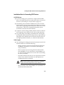
ARO-1130CA Layout
Figure 2-1 identifies the major ARO-1130CA components. You may
find it helpful to refer to this information while installing the
ARO-1130CA.
DIMM Memory Socket
Must be populated with a
168-pin 16-, 32-, or 64-MByte
EDO, 3.3v DIMM
LED Connector
Connects to the computer’s LED cable
to display activity on the SCSI bus
Bus Contacts
Inserted into the PCI/RAIDport II
expansion slot
Expansion Slot Bracket
Secures the RAIDport II card
inside your computer
BIOS EPROM
Provides booting
capabilities from a SCSI
hard disk or array
Figure 2-1. ARO-1130CA Major Components
Note: The model number that is printed on the board itself is
ARO-1130CA-B.
2-2
Installing the ARO-1130CA and Connecting SCSI Devices
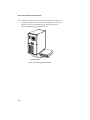
Verifying Presence of DIMM Memory
Before you can use the ARO-1130CA, the DIMM memory socket
must be populated with a 168-pin, 16-, 32-, or 64-MByte, EDO 3.3v
60ns or faster DIMM, as shown in Figure 2-2. Install a DIMM if one
is not yet installed. (See the Adaptec Web Site at http://
www.adaptec.com/RAID for a list of approved SIMMs and vendors.)
16-, 32-, or 64-MByte DIMM
Figure 2-2. Installing a DIMM in the DIMM Memory Socket
2-3
ARO-1130CA Installation and Hardware Guide
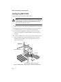
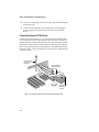
Installing the ARO-1130CA
Follow these steps to install the ARO-1130CA:
Note: If you are installing the ARO-1130CA in an existing system that already has data, back up all data before continuing
with installation. You can restore the data later once your
ARO-1130CA arrays are created.
1
Turn OFF power to the computer, and disconnect the power cord.
2
Remove the cover from the computer case. (If necessary, refer
to the instructions in your computer documentation.)
3
Locate the PCI/RAIDport II expansion slot; unscrew and
remove the expansion slot bracket that covers the card-slot
opening.
4
Insert the ARO-1130CA in the slot; press down firmly so that
the bus contacts are securely seated in the slot. Secure the
adapter bracket with the screw you removed in Step 3, as
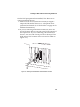
shown in Figure 2-3.
Expansion Slot
Bracket Screw
RAIDport II Card Bracket
Bus Contacts
PCI Expansion Slots RAIDport II Expansion Slot
Figure 2-3. Installing the ARO-1130CA in a Typical PCI/RAIDport II Expansion Slot
2-4
Installing the ARO-1130CA and Connecting SCSI Devices
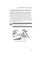
Connecting the LED Activity Indicator to the ARO-1130CA
(Optional feature) An LED on the front panel of most computers
lights to indicate non-SCSI hard disk activity. If you would like that
LED to light whenever there is activity on SCSI channel A (controlled by ARO-1130CA) instead, you must disconnect the LED
cable from the motherboard and connect it to the LED connector on
the ARO-1130CA. If the LED has a two-position cable, connect the
cable to pins 1 and 2 of the LED connector, as shown in Figure 2-4.
If the ARO-1130CA supports multiple SCSI channels, and you want
the LED to light whenever there is activity on any of those channels,
refer to your motherboard documentation for instructions on setting
the appropriate motherboard jumpers.
Note: If you are using non-SCSI disk drives (e.g., IDE), the
LED may no longer indicate activity on these drives when
you connect the LED cable to the ARO-1130CA.
LED Cable
1
1
2-pin LED Cable
1
LED Connector
on ARO-1130CA
Figure 2-4. Connecting the LED Activity Indicator
2-5
ARO-1130CA Installation and Hardware Guide
Connecting SCSI Devices
The ARO-1130CA supports both internal and external SCSI devices.
Depending on the number of SCSI channels provided on the motherboard. Each channel supports up to 15 SCSI devices—either 16-bit
devices alone or a combination of 16-bit and up to seven 8-bit
devices.
Note: If you are installing your SCSI devices inside an array
enclosure, see Connecting SCSI Array Enclosures (Storage Subsystems) on page 2-12.
Choosing SCSI Cables
To connect your SCSI devices, make sure you have the appropriate
cable and connectors as described in the following table (see also
Cable Lengths on page 2-13 for additional information on cabling SCSI
devices):
To Install…
You Will Need…
8-bit Internal SCSI Devices
• A 50-pin internal SCSI cable with enough connectors
to accommodate all of your internal SCSI devices.
16-bit Internal SCSI Devices
• A 68-pin Ultra Wide internal SCSI cable with enough
connectors to accommodate all of your internal SCSI
devices.
8-bit External SCSI Devices1
• A 50-pin internal-to-external SCSI port expansion kit.
• A 50-pin external SCSI cable for each device.
16-bit External SCSI Devices1
• A 68-pin Ultra Wide internal-to-external SCSI port
expansion kit.
• A 68-pin Ultra Wide external SCSI cable for each
device.
Array Enclosure
• A 68-pin Ultra Wide internal-to-external SCSI port
expansion kit.
• A 68-pin Ultra Wide external SCSI cable.
1 Use
2-6
only high-quality external cables with a single-ended impedance range of 80-110 ohms.
Installing the ARO-1130CA and Connecting SCSI Devices
Connecting Internal SCSI Devices
Follow these steps to connect internal devices:
1
Prepare each SCSI device for installation.
■
Make sure each device (internal and external) is assigned a
unique SCSI ID number from 0 to 15—no duplicate IDs are
permitted on a channel. (See SCSI ID Numbers on page 2-14
for additional information.)
■
Install (or enable) the terminators on the internal device
you are attaching to the end of the cable only. (See SCSI Termination on page 2-14 for additional information.)
2
Install and mount each internal SCSI device in an available
drive bay inside your computer. (Refer to your computer and
device documentation for instructions.)
3
If you are connecting 8-bit internal SCSI devices, attach one end
of the 50-pin cable to the 50-pin internal SCSI connector on the
motherboard. If you are connecting 16-bit internal SCSI devices,
attach one end of the 68-pin cable to the 68-pin internal SCSI
connector on the motherboard. Figure 2-5 shows a typical installation of a 68-pin cable.
68-pin Ultra wide
Internal SCSI Cable
68-pin Ultra wide
SCSI Connector
Figure 2-5. Attaching 68-pin Internal Ribbon Cable
2-7
ARO-1130CA Installation and Hardware Guide
4
Attach the remaining connectors on the cable to the remaining
internal devices.
5
Connect an available DC power cable (from your computer’s
power supply) to the power input connector on each SCSI
device.
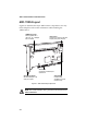
Connecting External SCSI Devices
To install external SCSI devices, you will first need to install an internal-to-external SCSI port expansion kit. The kit usually consists of a
special cable that converts the internal SCSI connector on the motherboard to an external SCSI connector on the chassis of your computer.
Refer to the expansion kit documentation for installation instructions.
Figure 2-6 shows a typical installation of a 68-pin Ultra Wide internalto-external cable.
68-Pin Ultra Wide
External SCSI
Connector
68-Pin Ultra Wide
Internal-to-External
SCSI Cable
68-Pin Ultra Wide
Internal SCSI
Connector
Figure 2-6. Installing an Internal-to-External SCSI Port Expansion Cable
2-8
Installing the ARO-1130CA and Connecting SCSI Devices
Once the SCSI port expansion kit is installed, follow these steps to
connect external SCSI devices:
1
Make sure each device (internal and external) is assigned a
unique SCSI ID number from 0 to 15—no duplicate IDs are
permitted on a channel. (See SCSI ID Numbers on page 2-14 for
additional information.)
2
If you are connecting 8-bit external SCSI devices, attach one
end of the 50-pin cable to the 50-pin external SCSI connector of
the expansion kit. If you are connecting 16-bit external SCSI
devices, attach one end of the 68-pin cable to the 68-pin Ultra
Wide external SCSI connector of the expansion kit (shown in
Figure 2-7.)
Figure 2-7. Attaching an External Cable to the External SCSI Connector
2-9
ARO-1130CA Installation and Hardware Guide
3
Attach the connector at the other end of the cable to either one
of the SCSI connectors on the external SCSI device, as shown in
Figure 2-8. (If you are installing only one external device,
attach a terminating plug to the device.)
3
Terminating Plug
Figure 2-8. Attaching a Single External Device
2-10
Installing the ARO-1130CA and Connecting SCSI Devices
Connect other external SCSI devices by daisy-chaining each
device to the previous device until all external SCSI devices
have been connected, as shown in Figure 2-9. (The device at
the end of the chain must have a terminating plug installed.
See SCSI Termination on page 2-14 for additional information.)
3
4
2
4
Terminating Plug
Figure 2-9. Attaching Multiple External Devices
2-11
ARO-1130CA Installation and Hardware Guide
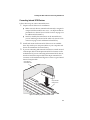
Connecting SCSI Array Enclosures (Storage Subsystems)
To help you conveniently manage your SCSI storage subsystems, a
variety of array enclosures are available from different manufacturers. Figure 2-10 shows a typical setup between the array enclosure
and the system. To install your SCSI devices in these enclosures,
refer to the enclosure’s documentation. The following information is
provided to help you properly connect your enclosure to the system:
■
All rules for SCSI ID and termination must be followed when
installing SCSI devices in an array enclosure.
■
Ideally, the array enclosure itself should provide termination
capability and you should disable termination on all the drives
in the enclosure. If you terminate the SCSI bus by enabling termination on a drive, you may run into problems if you have to
replace that drive and you then forget to terminate the replacement drive.
■
If the enclosure you are using for the array drives is not specifically designed as an array enclosure (such as a standard tower
unit), be sure it has adequate cooling and ventilation.
Array Enclosure
System
Figure 2-10. A Typical Array Enclosure Setup
2-12
Installing the ARO-1130CA and Connecting SCSI Devices
Installation Hints for Connecting SCSI Devices
All SCSI Devices
■
If you are booting your system from a single SCSI hard disk
drive or bootable array, the boot order of the disk or array must
be set to 0. (See Making the Array Bootable on page 3-7.)
■
Termination power should be enabled on several or all SCSI
devices in the system (or array enclosure) so that if you remove
a drive that is supplying termination power other devices will
still provide it. The devices supplying termination power
should be located near the end of the bus.
■
Symptoms of SCSI cabling-related problems are drives that are
not recognized, drives that lock-up, or drives that deactivate.
■
Use good-quality SCSI cabling, and minimize the stub lengths.
Good-quality cables should not be limp when you pick them up.
The quality of the cable becomes much more critical when you
use higher-speed data transfer (i.e., UltraSCSI data transfer).
Cable Lengths
■
The total length of cabling (internal and external) on each SCSI
channel should not exceed the following:
–
Three m (9.8 ft) if you are using Fast SCSI data transfer rates
(10 MBytes/sec) and have 1 to 15 devices (including the
Array controller).
–
Three m (9.8 ft) if you are using UltraSCSI data transfer
rates (20 MBytes/sec for 8-bit devices, and 40 MBytes/sec
for 16-bit devices) and have four or less devices (including
the Array controller).
–
One and one-half m (4.9 ft) if you are using UltraSCSI data
transfer rates and have between four and eight devices
(including the Array controller).
Note: UltraSCSI data transfer rates do not currently
support more than eight devices per channel.
–
Six m (19.7 ft) if you are using 5-MByte/sec asynchronous or
synchronous data transfer rates.
2-13
ARO-1130CA Installation and Hardware Guide
■
When calculating the total length of the bus, be sure to include
the cabling inside any array enclosure.
SCSI ID Numbers
Each device attached to a SCSI channel supported by the
ARO-1130CA must be assigned a unique SCSI ID number—0 to 15
for Wide (16-bit) devices, and 0 to 7 for Narrow (8-bit) devices. No
duplicate IDs are permitted on a channel.
■
We recommend that you leave the Array controller set to its
default setting of SCSI ID 7. If for some reason you need to
change the Array controller SCSI ID, see Chapter 5, Configuring
the ARO-1130CA with the SCSISelect Utility for instructions.
■
SCSI ID 7 has the highest priority on the channel. The priority
of the remaining IDs, in descending order, is 6 to 0, 15 to 8.
■
If you have 8-bit SCSI devices, they must use SCSI IDs 0, 1, 2, 3,
4, 5, or 6. (To change the SCSI ID on your hard disk and other
SCSI devices, refer to the device’s documentation.)
■
If you wish to use a single SCSI disk drive (instead of an array)
as your boot device, we recommend that you set the SCSI ID
for the device to 0.
■
In general, use lower SCSI IDs for single disks and use higher
SCSI IDs for drives used as array members or spares.
SCSI Termination
To ensure reliable communication on the SCSI bus, terminators must
be installed (or enabled) on the devices at the physical ends of each
SCSI channel. The terminators on all devices between the physical
ends must be removed (or disabled).
To properly terminate the SCSI channel(s) on your system, refer to
the motherboard documentation. On most internal SCSI devices, the
termination setting is controlled by setting a jumper or a switch, or
by physically removing or installing a resistor module(s). On most
external SCSI devices, termination is controlled by installing or
removing a terminating plug (see Figures 2-8 and 2-9). Refer to the
device’s documentation to determine how to enable or disable termination on your particular SCSI device.
2-14
Installing the ARO-1130CA and Connecting SCSI Devices
Completing the Installation
Reinstall your computer cover and connect all power cables. To
verify that the SCSI devices work properly, turn ON the external
SCSI devices first, then turn ON the computer. When the computer
boots, the Array1000CA Family BIOS sign-on message should
appear on the screen. If the BIOS message does not appear, see
Appendix A, Troubleshooting.
Note: If you need to configure the SCSI options (e.g., ID, Parity Checking, and Termination) of the SCSI channels supported by the ARO-1130CA, see Chapter 5, Configuring the
ARO-1130CA with the SCSISelect Utility.
❒
2-15
▼ ▼ ▼ ▼
3
Creating the First Array
With the ArrayConfigCA
Program
This chapter explains how to use the Adaptec ArrayConfigCA program to create the first bootable or nonbootable array on your computer. Before creating the array, make sure the disks for the array are
connected and installed in your computer (or array enclosure). You
can use ArrayConfigCA in two ways:
■
Select Express Setup if you want to create an array quickly and
easily. ArrayConfigCA asks you a few simple questions and
uses your answers to create the kind of array that best meets
your needs.
■
Select Custom Setup if you want to perform advanced operations, such as creating an array with more than two disks or
adding spare disks to an array.
ArrayConfigCA runs from a convenient, self-booting diskette. All
ArrayConfigCA functions, except creating bootable arrays, can also
be performed with Adaptec CI/O Workstation Array Management
Software, which runs under Windows NT.
Additional information on using ArrayConfigCA to create, delete,
and manage arrays and spares is available in the Adaptec
ARO-1130CA Array Management Guide.
3-1
ARO-1130CA Installation and Hardware Guide
Creating an Array with Express Setup
ArrayConfigCA’s Express Setup option allows you to quickly create
an array by answering some basic questions about what kind of
array you want. This process is similar to the wizards used in many
Windows® programs. When you use the Express Setup option you
do not need to know the technical details of how arrays are
configured.
Follow these steps to create an array with Express Setup. (You can
probably complete the Express Setup process simply by following
the instructions that appear on the screen.)
Note: ArrayConfigCA requires at least one available SCSI
hard disk drive in order to create an array (a one drive
RAID 0 array is supported to achieve maximum single drive
caching performance). (“Available” means that the disk
drive is not already being used to store data.) To select
ArrayConfigCA menu options, type the hot key—the letter
that appears in a different color. (The hot key letters are
underlined in the following instructions). You can also press
the ↑ and ↓ keys until the option is highlighted and then
press Enter.
1
Insert the ArrayConfigCA diskette in drive A and reboot your
computer. Wait until ArrayConfigCA starts automatically.
2
Read the text that appears on the initial ArrayConfigCA
screens. Press any key to view the next screen, or press Esc to
return to the previous screen.
3
When you see the Setup Type Selection Menu, select Express
Setup.
4
When the next screen appears, select the type of array you
want to create:
–
3-2
Select Optimized for Performance if you want the fastest
possible data input and output from the new array. This
kind of array does not have special data protection features, however. When prompted, type the number of disks
you want in this array.
Creating the First Array With the ArrayConfigCA Program
–
Select Optimized for Data Protection if your main concern
is to protect the files on the array from disk failure. This
kind of array safeguards files in the array even if one of the
array disks fails. (This kind of array has two disks by definition, so you will not be prompted to enter the number of
disks you want in the array.)
5
When the next menu appears, select the type of application
that you will run on your computer. (Select Others if you are
not sure what type of application you will use.)
ArrayConfigCA will use your answer to create the best array
configuration for your applications.
6
When the next menu appears, select a boot order for the new
array.
7
–
Select Disk Array will be Boot Drive if you want your
computer to boot from the new array. If you selected Optimized for Data Protection in Step 4, booting from an array
safeguards the information on your boot drive. (To boot
from an array, you must also install the operating computer
software on the array, as described in Chapter 4, Installing
Software on a Windows NT System.)
–
Select Disk Array will not be a Boot Drive if you do not
want your computer to boot from the new array.
When you have finished all these menu selections, wait while
ArrayConfigCA creates the array. This may take a long time,
especially if the disk drives are large.
A message appears when the array has been created. An error
message appears if fewer than two disks are available or if
ArrayConfigCA encounters some other problem. If this happens, install more disk drives or run ArrayConfigCA again and
use the Custom Setup option.
3-3
ARO-1130CA Installation and Hardware Guide
Creating an Array with Custom Setup
ArrayConfigCA’s Custom Setup option allows advanced users to
create arrays with customized configuration and to manage arrays
that are already created. Use Custom Setup if you want to
■
create an array with more than two disks
■
delete an array
■
initialize an array
■
add or delete spare disks
■
make an existing array the boot array
Follow these instructions to create an array with Custom Setup.
1
Insert the ArrayConfigCA diskette in drive A and reboot your
computer. Wait until ArrayConfigCA starts automatically.
2
Read the text that appears on the initial ArrayConfigCA
screens. Press any key to view the next screen, or press Esc to
return to the previous screen.
3
When you see the Setup Type Selection Menu, select Custom
Setup. Then wait while ArrayConfigCA scans your computer
for information about your host adapter and SCSI devices.
4
5
6
When the Main Menu appears, select Disk Array Operations.
7
Select Create New Array from the Disk Array Operations menu.
Type a name for the array and press Enter. The name can be up
to 15 characters long and can include spaces and any other
printable characters.
Select an array type from the following options:
–
RAID 0: Data is striped across the disks in a RAID 0 array,
allowing for faster data input and output than a single
disk. RAID 0 arrays do not store redundant data; if any
disk in the array fails, all data is lost.
–
RAID 1: Data is mirrored on one pair of disks. If one disk
fails, data is still safe. The actual data capacity of the array
equals half the available disk space.
See the Adaptec ARO-1130CA Family Array Management Guide
for more information on selecting a RAID level.
3-4
Creating the First Array With the ArrayConfigCA Program
8
Type the number of drives you want in the array (this does not
include spares) and press Enter. The number of drives available for assignment is listed on the screen.
Note: You do not choose a number of drives when creating a RAID 1 arrays, because RAID 1 arrays have
two drives by definition. A spare is a drive that will be
used automatically as a replacement if one of the array
member drives fails.
9
When the next screen appears, press Tab to highlight a channel
(if your Adaptec array card uses more than one SCSI channel).
Select drives for the array by pressing the ↑ and ↓ keys until
the drive name is highlighted, and then press Ins or Enter. The
names of selected drives appear in the box on the right side of
the screen.
To select drives on a different channel (if necessary) press Tab
to select another channel and then select the drives from the
SCSI IDs on the Channel menu. To deselect the drive you most
recently added, press Del.
Caution: A warning appears if you select a disk that has
partitions. Do not select disks with partitions if they contain data you want to keep, because any existing data
will be erased when the disk becomes part of the array.
When you have selected the number of drives you specified in
Step 8, the next screen appears automatically. If you are creating a RAID 1 array, and if there are any unassigned drives, the
screen prompts you to define spare drives for the array.
Note: A spare must have at least the capacity of the
smallest drive in the array.
10
If you do not want a spare, type n and continue with Step 12. If
you want to select dedicated spares, follow these steps:
a At the prompt, type y.
3-5
ARO-1130CA Installation and Hardware Guide
b At the next prompt, type 1 or 2.
c Select one or two spares, using the same method you used
to select disks for the array.
11
When the Initialize Mode menu appears, select Initialize
Array to Zero. This operation begins immediately. A graph on
the screen shows the progress of this operation. You cannot
cancel the initialization once it has started.
Caution: If the drives contain data, all the data is lost
when you initialize the array.
Select Low-Level Format only if the drives were previously
formatted on another computer or if you think they may have
surface defects. Low-level formatting takes a long time for
large disk drives.
12
When the menu of block sizes appears, select a block size. (This
menu does not appear if the array is a mirrored array with only
two drives.)
The default block size (64 KBytes) gives the best overall
performance. The allowable block sizes are 8, 16, 32, 64, and
128 KBytes.
13
When you see the message Initialization of [array name] is complete, press any key to return to the Disk Array Operations
menu.
14
To create additional arrays (if disks are available), return to
Step 5. When all arrays are created, exit from ArrayConfigCA,
remove the ArrayConfigCA diskette, and reboot the computer.
After you reboot you can write data to the arrays.
At this point, you can make your initial array bootable as
described in the next section.
For information on other Custom Setup options, or information on
using ArrayConfigCA to create, delete, and manage arrays and
spares, refer to the Adaptec ARO-1130CA Array Management Guide.
3-6
Creating the First Array With the ArrayConfigCA Program
Making the Array Bootable
You can make the array bootable so that the computer boots from
the array instead of from a stand-alone (single) disk. To make the
array bootable, the array must be set to #0 in the boot order. We recommend that you make your initial array bootable. Follow these
steps if you want the computer to boot from the newly created array:
Note: The computer will always attempt to boot from any
installed non-SCSI disks (for example, any IDE disk drive at
drive C). You must disable or remove all non-SCSI disks if
you want the computer to boot from a SCSI disk or array.
1
Insert the ArrayConfigCA diskette in the computer’s floppy
disk drive A.
2
Reboot the computer from the diskette. ArrayConfigCA starts
automatically.
3
Select Display Boot Order from the Main Menu. The Boot
Order for Singles and Arrays window appears.
4
If the newly created array is at the top of the list, preceded by
the words Unit 0, no changes are necessary; if it has some other
unit number, highlight the array name and press Enter.
5
Use the arrow keys to move the selected array to the top of the
list. Then press Enter. If you want to change the boot order of
another array, select it, move it with the arrow keys, and press
Enter again.
6
Press Esc to return to the Main Menu.
7
Exit ArrayConfigCA, remove the diskette from drive A, and
reboot the computer.
8
Prepare the array as you normally would prepare a boot disk
drive for your operating system. See Chapter 4, Installing Software on a Windows NT System.
3-7
ARO-1130CA Installation and Hardware Guide
Note: You cannot designate a stand-alone SCSI disk drive
the boot order of Unit 0. If you want to do this, create a onedisk RAID 0 array from the stand-alone disk drive and then
designate it as Unit 0.
❒
3-8
▼ ▼ ▼ ▼
4
Installing Software on a
Windows NT System
This chapter explains how to install the software required to use the
ARO-1130CA in a system using Windows NT Workstation 4.0.
Before installing the software, make sure the ARO-1130CA is
already installed. If you plan to boot from an array, make sure the
array is already created. To install all of the software, you must complete the following in the order presented:
■
Install the Array1000CA driver for Windows NT
■
Install the Adaptec CI/O Workstation Array Management
Software for Windows NT
Once all software is installed, refer to the Adaptec ARO-1130CA Array
Management Guide for instructions on adding, deleting, and managing your arrays.
Note: If your RAIDport II On Board system has an Adaptec
AHA-2940, AHA-3940, or any other AIC™-78x0 based host
adapter installed (which is not associated with the
RAIDport), the aic78xx.sys driver for these host adapters
must be from the Adaptec 7800 Family Manager Set 1.3 or
later.
4-1
ARO-1130CA Installation and Hardware Guide
Installing the Array1000CA Driver for Windows NT
This section explains how to install the Array1000CA Miniport
Driver (cda1000.sys) for Windows NT. To begin driver installation,
see either Installing the Driver When Installing Windows NT below, or
Installing the Driver When Windows NT is Already Installed on
page 4-3.
Note: We recommend that you install your Windows NT
operating system on an array to take advantage of the performance or redundancy features of the array.
Installing the Driver When Installing Windows NT
To install the cda1000.sys driver when you are installing Windows
NT, follow the instructions below.
Note: If you have multiple arrays, we recommend temporarily powering off all devices except for the boot array
before installing Windows NT; otherwise, Windows NT limits the size of the partitions you can create to 1 GByte. When
Windows NT installation is complete, power on all devices
and reboot the system.
Windows NT 4.0 Installation
To install the cda1000.sys driver when you are installing Windows
NT 4.0, follow these steps:
1
Start your system with the Windows NT Boot Diskette in the
floppy disk drive or the Windows NT Boot CD-ROM in the
CD-ROM drive.
2
Boot diskette installation: When prompted, insert diskette #2 in
your floppy drive. After a few moments you will see a blue
screen. To setup Windows NT now, press Enter and continue
with Step 3 below.
Boot CD-ROM installation: When the following message
appears onscreen, press the F6 key and skip to Step 4 below.
Setup is inspecting your computer’s hardware…
4-2
Installing Software on a Windows NT System
3
4
5
Press S to skip autodetection of your SCSI host adapter.
6
The screen displays the adapter drivers supported on the
diskette. Select the Adaptec Array1000CA Family Adapter and
press Enter.
7
If you want to add drivers for other host adapters (other than
the ARO-1130CA), do so at this time by pressing S and repeating Step 5 for each additional adapter and inserting the appropriate disk provided by the hardware manufacturer.
8
Press Enter to continue with the Windows NT operating
system setup. Follow the onscreen instructions in the Windows
NT documentation to complete the installation.
Press S again to specify an additional device.
Press Enter to select Others; insert the Adaptec Array100
Family Manager Set drivers diskette in your floppy disk drive.
Installing the Driver When Windows NT is Already Installed
To update or install the cda1000.sys driver if Windows NT is
already installed, follow the instructions below.
Updating Windows NT 4.0
To install the cda1000.sys driver when Windows NT 4.0 is already
installed, follow these steps:
1
2
Start Windows NT.
3
4
5
6
7
Click the Control Panel.
Click the Start button on the Windows NT task bar, and then
point to Settings.
Double-click the SCSI Adapters icon.
Click the Drivers tab, and then click the Add button.
In the Install Driver window, click the Have Disk button.
Insert the Adaptec Array1000CA Family Manager Set drivers
diskette into drive A; enter the following path to the installation files and then click OK.
a:\winnt
The Adaptec Array1000CA Family Adapter is highlighted by
default.
4-3
ARO-1130CA Installation and Hardware Guide
8
9
In the Install Driver window, Click OK.
Click the New button when asked if you want to use the currently installed driver(s) or install new one(s).
10
Type a:\winnt again, and click Continue. The driver is now
installed.
11
You must restart your computer for the changes to take effect.
Click Yes to restart your computer.
Installing Adaptec CI/O Workstation Array
Management Software for Windows NT
Follow these steps to install the Adaptec CI/O Workstation Array
Management Software for Windows NT:
1
Start Windows NT.
2
Insert the Adaptec CI/O Workstation Array Management Software CD-ROM in your CD-ROM drive. If you are installing the
software from diskettes, insert Disk 1 of the Adaptec CI/O
Workstation Array Management Software for Windows NT in
the floppy disk drive.
3
Select Run from the File menu, type the following and press
Enter:
[pathname]setup.exe
(The setup.exe file is located at \win_nt\disk1\setup.exe on the
CD-ROM, and at \setup.exe on Disk 1 of the Adaptec CI/O
Workstation Array Management Software for Windows NT.)
4
Follow the directions that appear on the screen.
5
When installation is complete, reboot the system. The following NT Services start automatically in the background:
CIO Array Management Service
Note: This NT Service is configured to start automatically at boot time. After installation you can start or
stop this service through the Services icon in the
Windows NT Control Panel.
4-4
Installing Software on a Windows NT System
6
Double-click the CI/O Array Management Software icon to
start the program.
See the Adaptec ARO-1130CA Array Management Guide for information on using the Adaptec CI/O Workstation Array Management
Software to add, delete, or manage your arrays. If you are experiencing problems starting the software, see Problems Running the Software
On Your Windows NT Workstation on page A-2.
❒
4-5
▼ ▼ ▼ ▼
5
Configuring the
ARO-1130CA with the
SCSISelect Utility
The Array1000CA SCSISelect® configuration utility allows you to
change controller settings without opening the computer or handling the controller. This chapter describes the default settings,
explains when you should change them, and gives instructions for
doing so.
Array1000CA SCSISelect also includes SCSI disk utilities to list the
SCSI IDs of devices controlled by the ARO-1130CA, format SCSI
disk drives, and check them for defects. Instructions for using these
utilities are included.
5-1
ARO-1130CA Installation and Hardware Guide
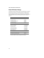
Default SCSISelect Settings
The default SCSISelect settings, shown in the table below, are appropriate for most systems. For situations where you might want or
need to change the settings, see the descriptions of each setting
beginning on page 5-5. To change any setting, or if you would like to
run the SCSISelect utilities, see Starting the SCSISelect Utility on
page 5-3.
1
SCSI Bus Interface Definitions
Default
Host Adapter SCSI ID
7
SCSI Parity Checking
Enabled
Host Adapter SCSI Termination
Enabled
Host Adapter UltraSCSI
Disabled
SCSI Device Configuration
Default
Initiate Sync Negotiation
Yes (Enabled)
Maximum Transfer Rate
40.0 MBytes/sec.1
Enable Disconnection
Yes (Enabled)
Initiate Wide Negotiation2
Yes (Enabled)
Send Start Unit Command
No (Disabled)
Include In BIOS Scan
Yes (Enabled)
Additional Options
Default
Array 1000 BIOS
Enabled
BIOS Support for Bootable CD-ROM
Disabled
If Wide SCSI is not supported on the motherboard, the default setting is 20.0 MBytes/sec.
is available only if Wide SCSI is supported on the motherboard.
2 This option
5-2
Configuring the ARO-1130CA with the SCSISelect Utility
Starting the SCSISelect Utility
To start SCSISelect, press Ctrl-A when the following prompt appears
when you turn on or reboot your computer:
Press <Ctrl><A> for SCSISelect (TM) Utility!
The menu that appears displays the options Configure/View Host
Adapter Settings and SCSI Disk Utilities, as shown in Figure 7-1.
Adaptec Array 1000 Family
SCSISelect(TM)
Utility v2.00
Adaptec Array 1000 Family at Bus:Channel 00:C
Would you like to configure the PCI device, or run the
SCSI disk utilities? Select the option and press <Enter>.
Press <F5> to switch between color and monochrome modes.
Options
Configure/View Host Adapter Settings
SCSI Disk Utilities
Arrow keys to move cursor, <Enter> to select option, <Esc> to exit (* =default)
Figure 7-1. SCSISelect Menu
Using SCSISelect Menus
To select a SCSISelect menu option, move the cursor to the option
with the ↑ and ↓ keys, then press Enter. In some cases, selecting an
option displays another menu. You can return to the previous menu
at any time by pressing Esc.
To restore the original SCSISelect default values, press F6 from the
main SCSISelect screen. To toggle the display between color and
monochrome modes, press F5 from the main SCSISelect screen (this
feature does not work on some monitors).
5-3
ARO-1130CA Installation and Hardware Guide
Exiting SCSISelect
To exit SCSISelect, press Esc until a message prompts you to exit (if
you changed any host adapter settings, you are prompted to save
the changes before you exit). Select Yes to exit, then press any key to
reboot the computer. Any changes you made in SCSISelect take effect
after the computer boots.
Using the SCSI Disk Utilities
To access the SCSI disk utilities, select the SCSI Disk Utilities
option from the menu that appears after starting SCSISelect. Once
the option is selected, SCSISelect immediately scans the SCSI bus (to
determine the devices installed) and displays a list of all SCSI IDs
and the devices assigned to each ID.
When you select a specific ID and device, a small menu appears, displaying the options Format Disk and Verify Disk Media.
■
Format Disk—This utility allows you to perform a low-level
format on a hard disk drive. Each hard disk drive must be lowlevel formatted before you can use your operating system’s
partitioning and file preparation utilities, such as MS-DOS
Fdisk and Format.
Most SCSI disk devices are preformatted at the factory and do
not need to be formatted again. The Adaptec Format Disk utility is compatible with the vast majority of SCSI disk drives.
Caution: A low-level format destroys all data on the
drive. Be sure to back up your data before performing
this operation. You cannot abort a low-level format
once it is started.
■
5-4
Verify Disk Media—This utility allows you to scan the media
of a hard disk drive for defects. If the utility finds bad blocks
on the media, it prompts you to reassign them; if you select yes,
those blocks are longer used. You can press Esc at any time to
abort the utility.
Configuring the ARO-1130CA with the SCSISelect Utility
SCSISelect Settings
SCSI Bus Interface Definitions
The following settings are the SCSISelect settings most likely to
require any modification.
■
Host Adapter SCSI ID— This option sets the ARO-1130CA’s
SCSI ID. The default setting is SCSI ID 7, which gives the
ARO-1130CA the highest priority on the SCSI bus. We recommend that you leave the ARO-1130CA set to SCSI ID 7.
■
SCSI Parity Checking—This option determines whether the
ARO-1130CA verifies the accuracy of data transfer on the SCSI
bus. The default setting is Enabled. You should disable SCSI
Parity Checking on the ARO-1130CA and all SCSI devices if
any SCSI device supported by the ARO-1130CA does not support SCSI parity; otherwise, leave it enabled. Most SCSI
devices do support SCSI parity. If you are not sure whether a
device supports SCSI parity, consult the documentation for the
device.
■
Host Adapter SCSI Termination—This option is used in conjunction with your motherboard termination settings. Refer to
your motherboard documentation for instructions on properly
setting termination.
■
Host Adapter UltraSCSI—This option determines whether the
ARO-1130CA supports UltraSCSI data transfer speeds. The
default setting is Disabled. If you have any UltraSCSI devices
installed, you should enable this setting. When this setting is
enabled, the ARO-1130CA negotiates for data transfer speeds
of up to 20 MBytes/sec (40 MBytes/sec for Wide SCSI devices).
Note: If you use UltraSCSI data transfer speeds, be
sure to use high-quality cables to connect the disk
drives supported by the ARO-1130CA. The quality of
the cable is much more critical when you use higherspeed data transfer.
5-5
ARO-1130CA Installation and Hardware Guide
SCSI Device Configuration
The SCSI device settings allow you to configure certain parameters
for each device on the SCSI bus. To configure settings for a specific
device, you must know the SCSI ID assigned to that device. If you are
not sure of the SCSI ID, see Using the SCSI Disk Utilities on page 5-4.
■
Initiate Sync Negotiation—This option determines whether
synchronous data transfer negotiation (Sync Negotiation)
between the device and ARO-1130CA is initiated by the SCSI
channel controlled by the ARO-1130CA. Normally, you should
leave Initiate Sync Negotiation set to enabled, because most
SCSI devices support synchronous negotiation and because it
allows for faster data transfer. The default setting is Yes.
■
Maximum Transfer Rate—This option determines the maximum data transfer rate that the SCSI channel controlled by the
ARO-1130CA supports. The default setting is 20.0 MBytes/sec
(10 MBytes/sec for motherboards that do not support Wide
SCSI). (The effective data transfer rate is doubled when Initiate
Wide Negotiation is set to Yes. For example, a transfer rate of
20 MBytes/sec becomes 40 MBytes/sec.)
■
Enable Disconnection—This option determines whether the
SCSI channel controlled by the ARO-1130CA allows the SCSI
device to disconnect from the SCSI bus (sometimes called
Disconnect/Reconnect). The default setting is Yes.
You should leave Enable Disconnection set to Yes if two or
more SCSI devices are supported by the ARO-1130CA. If only
one SCSI device is supported by the ARO-1130CA, you can set
Enable Disconnection to No to achieve slightly better performance.
■
5-6
Initiate Wide Negotiation—This option determines whether
the SCSI channel controlled by the ARO-1130CA attempts
16-bit data transfer instead of 8-bit data transfer. The default
setting is Yes. (The effective data transfer rate is doubled when
16-bit data transfer is used. For example, a transfer rate of
10 MBytes/sec becomes 20 MBytes/sec.)
Configuring the ARO-1130CA with the SCSISelect Utility
■
Send Start Unit Command—This option determines whether
the Start Unit Command is sent to the SCSI device at bootup
(most devices do not require this). The default setting is No.
■
Include in BIOS Scan—This option determines whether the
ARO-1130CA BIOS supports hard disk drives attached to the
SCSI channel controlled by the ARO-1130CA. When set to Yes,
the ARO-1130CA BIOS controls the hard disk drive. When set
to No, the ARO-1130CA BIOS does not control the hard disk
drive. The default setting is Yes.
Additional Options
Array1000CA BIOS
This option determines whether the ARO-1130CA BIOS is installed
at boot time. When set to Enabled, the ARO-1130CA BIOS is
installed, and all Int13 (except bootable CD-ROM) devices are supported. When set to Disabled, the ARO-1130CA BIOS is not installed.
The default setting is Enabled.
BIOS Support for Bootable CD-ROM
This option determines whether the ARO-1130CA BIOS supports
booting from a CD-ROM drive. When set to Enabled, the
ARO-1130CA allows booting from a CD-ROM drive.
❒
5-7
▼ ▼ ▼ ▼
A
Troubleshooting
Troubleshooting Checklist
Check the following if you have problems installing or running the
ARO-1130CA and SCSI devices:
■
Does the ARO-1130CA BIOS sign-on message appear during
bootup? If not, check the following items:
–
Is the ARO-1130CA properly seated in a PCI/RAIDport
expansion slot? Refer to your computer documentation for
the slot location.
–
Does your computer CMOS setup require you to enable
PCI bus parameters (see your computer documentation)? If
so, run the CMOS Setup program and assign the parameters—usually IRQ, Enable PCI Slot, and Enable Master.
■
Is the SCSI bus terminated properly, and are all SCSI devices
turned on?
■
Are all SCSI bus cables and power cables connected?
■
Does each channel and each device on the channel have a
unique SCSI ID?
■
If you are having trouble booting from a SCSI disk drive or
array, make sure your computer’s CMOS setup is set to No
Drives Installed (the required setting for SCSI drives). Also,
verify that the drive or array has been selected as the boot-first
(boot) device and that the boot partition is active.
A-1
ARO-1130CA Installation and Hardware Guide
Problems Running the Software On Your
Windows NT Workstation
If the Adaptec CI/O Workstation Array Management Software does
not start when you double-click the program icon and you see a
warning box with Unable to Initialize IOMAPI, try the following:
■
Verify that the following NT service has a status of Started
(double-click the Services icon in Control Panel). If it does not,
select the service and press the Start button:
CIO Array Management Service
■
Make sure you have the proper security access rights to the
Windows NT services. The Windows NT services can be
started, stopped, paused, etc., according to the NT service
security rules defined by Microsoft (refer to the Windows NT
documentation for more details).
■
Verify that the Registry was updated correctly during installation. If the values do not match the values listed below, try
reinstalling the Adaptec CI/O Workstation Array Management Software:
–
The correct entries for HKEY_LOCAL_MACHINE\
SYSTEM\CurrentControlSet\Services\
CIOArrayManagement are:
DisplayName: REG_SZ: CIO Array Management
Service (v x.xx)
ErrorControl: REG_DWORD: 0x01
ImagePath: REG_SZ: [Pathname specified during
installation]iomgr.exe
ObjectName: REG_SZ: LocalSystem
Start: REG_DWORD: 0x02
Type: REG_DWORD: 0x110
SharedMemName: REG_SZ: iomgr.shm
–
The correct entries for HKEY_LOCAL_MACHINE\
SYSTEM\CurrentControlSet\Services\EventLog\System\
CIOArrayManagement are:
EventMessageFile: REG_SZ: [pathname to system32
directory]\system32\iomgrmsg.dll
TypesSupported: REG_DWORD: 0x7
A-2
Troubleshooting
■
Verify that the following DLLs are located in your system32
directory. If they are not present, try reinstalling the Adaptec
CI/O Workstation Array Management Software:
ctl3dnt.dll
xnmhb420.dll
xnmhn420.dll
xnmte420.dll
msvcrt20.dll
mtld.dll
xnmba420.dll
iomgrmsg.dll
■
Verify that the following files are located in the directory where
you installed the Adaptec CI/O Workstation Array Management Software. If they are not present try reinstalling the
software:
iomgr.ems
cioams.hlp
cioams.exe
readme.txt
iomgr.exe
iomgr.ini
iomgr.msg
A-3
ARO-1130CA Installation and Hardware Guide
Using the ARO-1130CA with an AHA-2940
Family Host Adapter
This section explains how to use an ARO-1130CA and an AHA-2940
Family host adapter in the same computer system. In order to do
this, you must load drivers. You also may need to make changes to
the Windows NT registry.
Caution: We recommend that you do not attempt these configuration changes unless you are an experienced computer
user.
Two scenarios are presented. Choose the one that matches what you
want to do.
Scenario #1: Adding an ARO-1130CA to a System with an
AHA-2940 Family Adapter
These instructions assume that Windows NT is already installed on
the computer system and that the boot drive is currently connected
to the AHA-2940 Family adapter. If the ARO-1130CA is already
installed, shut down the computer system, remove the ARO-1130CA
from the expansion slot, and restart the system.
Installing the ARO-1130CA Driver
1
Start the Windows NT Control Panel and double click the
SCSI Adapters icon.
2
Click the Drivers tab and click Add.
3
Click Have Disk …, and insert the Array1000CA Family Manager Set diskette in the floppy disk drive. (This diskette was
included with your ARO-1130CA adapter.)
4
When the Install from Disk dialog box appears, type A:\winnt
on the command line and click OK.
5
Select Adaptec Array1000CA Family Adapter and click OK.
6
When a message appears asking you if you want to restart
Windows NT, click No.
7
Exit from Control Panel.
A-4
Troubleshooting
Changing Registry Settings
1
Back up the NT Registry, using one of the techniques described
in Backing up the Windows NT Registry on page A-10
Caution: It is very important to back up the NT Registry before you make any changes to it. This allows you
to restore the original NT Registry settings if there is a
problem with the new configuration.
2
Run the Registry Editor (regedit.exe).
3
When the Registry Editor window appears, expand the tree on
the left until you can see the nodes under
\HKEY_LOCAL_MACHINE\System\CurrentControlSet\Services.
4
Select cda1000 on the left part of the screen. Write down the
cda1000 Tag value that appears on the right part of the screen.
The Tag value is a hex number followed by an equivalent decimal equivalent in brackets: for example, 0x00000002 [2].
5
Select aic78xx on the left part of the screen. Write down the
aic78xx Tag value that appears on the right part of the screen.
6
Expand the tree on the left until you can see the nodes under
\HKEY_LOCAL_MACHINE\System\CurrentControlSet\Control\GroupOrderList.
7
Select GroupOrderList.
8
Click the right mouse button on SCSI Miniport on the right
side of the window and select Modify from the popup menu.
A table appears with columns of two- and four-number
groups, something like this:
0005
0010
0015
0020
etc.
02
01
04
06
00
00
00
00
00
00
00
00
00
00
00
00
03
01
05
07
00
01
00
00
00
00
00
00
00
00
00
00
A-5
ARO-1130CA Installation and Hardware Guide
This table of hexidecimal numbers indicates the Tag-value
sequence in which the SCSI Miniport drivers are loaded when
you start Windows NT.
9
Determine what the Tag value loading sequence is. Here is
how you do this:
a Ignore the four-digit groups on the left of each row.
b Going from left to right, and starting on the first row,
divide the two-digit numbers into groups of eight. In this
example, the groups are
02 00
03 00
01 00
01 01
etc.
00
00
00
00
00
00
00
00
You need to write down all the number groups from all
rows in the table.
c In each group of eight numbers, reverse the sequence of the
two-digit pairs, like this:
00 00
00 00
00 00
00 00
etc.
00
00
00
01
02
03
01
01
d Write down the series of resulting numbers, without all the
extra zeroes. In this example, it is 2, 3, 1, 101, etc. This is the
Tag value loading sequence for SCSI Miniport drivers. In
other words, when Windows NT loads these miniport
drivers, the one with Tag value 2 is loaded first, then the
one with Tag value 3, and so on.
10
Compare the Tag value loading sequence to the actual tag values of cda1000 and aic78xx that you determined in steps 4
and 5. If cda1000 is loading before aic78xx, skip to step 16. If
aic78xx is loading first, continue with the next step.
11
Expand the tree on the left until you can see the nodes under
\HKEY_LOCAL_MACHINE\System\CurrentControlSet\Services.
A-6
Troubleshooting
12
Select cda1000 on the left part of the screen. Click the right
mouse button on Tag Value on the right part of the screen and
select Modify from the popup menu.
13
Type the tag value of the aic78xx miniport driver in the space
provided and click OK.
14
Select aic78xx on the left part of the screen. Click the right
mouse button on Tag Value on the right part of the screen and
select Modify from the popup menu.
15
Type the tag value of the cda1000 miniport driver in the space
provided and click OK. You have now reversed the tag values
for the two miniport drivers, and the cda1000 driver will load
first.
16
Exit from the Registry Editor and from Windows NT. Then
shut down the computer system.
17
Physically install the ARO-1130CA in the PCI/RAIDport
expansion slot.
18
Attach your boot drive to one of the SCSI channels controlled
by the ARO-1130CA and boot the computer system.
Scenario #2: Adding an AHA-2940 Family Adapter to a
RAIDport II System with an ARO-1130CA
These instructions assume that Windows NT is already installed on
the computer system and that the boot drive is connected to the
SCSI channel controlled by the ARO-1130CA. If the AHA-2940 Family adapter is already installed, shut down the computer system,
remove the adapter from the slot, and restart the system.
Installing the AHA-2940 Family Driver
1
Start the Windows NT Control Panel and double click the
SCSI Adapters icon.
2
Click the Drivers tab and click Add.
3
Click Have Disk …, and insert the AIC-78xx Family Manager
Set diskette in the floppy disk drive. (This diskette was
included with your 2940 Family adapter.)
A-7
ARO-1130CA Installation and Hardware Guide
4
When the Install from Disk dialog box appears, type A:\winnt
on the command line and click OK.
5
Select Adaptec Adaptec AHA-294x/AHA-394x or AIC-78xx
PCI SCSI Controller and click OK.
6
When a message appears asking you if you want to restart
Windows NT, click No.
7
Exit from Control Panel.
Changing Registry Settings
1
Back up the NT Registry, using one of the techniques described
in Backing up the Windows NT Registry on page A-10
Caution: It is very important to back up the NT Registry before you make any changes to it. This allows you
to restore the original NT Registry settings if there is a
problem with the new configuration.
2
Run the Registry Editor (regedit.exe).
3
When the Registry Editor window appears, expand the tree on
the left until you can see the nodes under
\HKEY_LOCAL_MACHINE\System\CurrentControlSet\Services.
4
Select cda1000 on the left part of the screen. Write down the
cda1000 Tag value that appears on the right part of the screen.
The Tag value is a hex number followed by an equivalent decimal equivalent in brackets: for example, 0x00000002 [2].
5
Select aic78xx on the left part of the screen. Write down the
aic78xx Tag value that appears on the right part of the screen.
6
Expand the tree on the left until you can see the nodes under
\HKEY_LOCAL_MACHINE\System\CurrentControlSet\Control\GroupOrderList.
7
Select GroupOrderList.
8
Click the right mouse button on SCSI Miniport on the right
side of the window and select Modify from the popup menu.
A-8
Troubleshooting
A table appears with columns of two- and four-number
groups, something like this:
0005
0010
0015
0020
etc.
02
01
04
06
00
00
00
00
00
00
00
00
00
00
00
00
03
01
05
07
00
01
00
00
00
00
00
00
00
00
00
00
This table of hexidecimal numbers indicates the Tag-value
sequence in which the SCSI Miniport drivers are loaded when
you start Windows NT.
9
Determine what the Tag value loading sequence is. Here is
how you do this:
a Ignore the four-digit groups on the left of each row.
b Going from left to right, and starting on the first row,
divide the two-digit numbers into groups of eight. In this
example, the groups are
02 00
03 00
01 00
01 01
etc.
00
00
00
00
00
00
00
00
You need to write down all the number groups in all rows
of the table.
c In each group of eight numbers, reverse the sequence of the
two-digit pairs, like this:
00 00
00 00
00 00
00 00
etc.
00
00
00
01
02
03
01
01
d Write down the series of resulting numbers, without all the
extra zeroes. In this example, it is 2, 3, 1, 101, etc. This is the
Tag value loading sequence for SCSI Miniport drivers. In
other words, when Windows NT loads these miniport
drivers, the one with Tag value 2 is loaded first, then the
one with Tag value 3, and so on.
A-9
ARO-1130CA Installation and Hardware Guide
10
Compare the Tag value loading sequence to the actual tag values of cda1000 and aic78xx that you determined in steps 4 and
5. If cda1000 is loading before aic78xx, skip to step 16. If
aic78xx is loading first, continue with the next step.
11
Expand the tree on the left until you can see the nodes under
\HKEY_LOCAL_MACHINE\System\CurrentControlSet\Services.
12
Select cda1000 on the left part of the screen. Click the right
mouse button on Tag Value on the right part of the screen and
select Modify from the popup menu.
13
Type the tag value of the aic78xx miniport driver in the space
provided and click OK.
14
Select aic78xx on the left part of the screen. Click the right
mouse button on Tag Value on the right part of the screen and
select Modify from the popup menu.
15
Type the tag value of the cda1000 miniport driver in the space
provided and click OK. You have now reversed the tag values
for the two miniport drivers, and the cda1000 driver will load
first.
16
Exit from the Registry Editor and from Windows NT. Then
shut down the computer system.
17
Physically install the AHA-2940 Family adapter in the expansion slot.
18
Boot the computer system.
Backing up the Windows NT Registry
It is very important to back up the Windows NT Registry before
making any changes to it. This will allow you to recover if the
changes make your system unusable. Here are two ways to back up
the Windows NT Registry. The backup utilities described here are
included with NT Workstation:
■
A-10
Use the ntbackup utility to create a tape copy of all data files
and Registry information. Be sure to select the Backup Local
Registry option when performing the backup.
Troubleshooting
■
Run the rdisk utility with the /s option to create a copy of the
Registry on a hard disk. (A typical backup file is 5 MBytes to
10 MBytes in size.) Then use xcopy or some other command to
copy the information to removable media. You must have the
three NT boot floppy disks to restore an RDISK-saved registry
to your computer system.
❒
A-11
▼ ▼ ▼ ▼
B
Advanced Topics
Installing Multiple Adapters
You cannot install more than one ARO-1130CA card in the same system unless the system is designed with more than one PCI/RAIDport slot; however, you can install an ARO-1130CA in computers that
have other PCI-, ISA-, or EISA-based host adapters installed. When
installing multiple adapters, keep the following considerations in
mind:
■
All drives in a single array must be connected to the same host
adapter. A single array cannot be created with drives from two
or more host adapters.
■
If you are booting from a SCSI disk drive or array supported
by the ARO-1130CA, then the ARO-1130CA must be the card
that the computer scans first. Some computers boot from the
device with the lowest PCI device number; others boot from the
device with the highest number. (See also Making the Array Bootable on page 3-7.) You can disable the BIOS on cards that are
scanned before the desired boot card.
■
In systems with EISA- and ISA-based host adapters, the boot
host adapter must have the lowest BIOS base address. The system
BIOS automatically controls the ARO-1130CA base address (the
user has no control over the assigned address).
❒
B-1
▼ ▼ ▼ ▼
C
Using a CD-ROM Drive
with DOS
To operate a SCSI CD-ROM drive connected to the ARO-1130CA
under DOS, you need
■
The SCSI driver, aspi8dos.sys (version 1.30 or later)
■
The CD-ROM driver, aspicd.sys
■
The Microsoft CD-ROM extensions, mscdex.exe
The aspi8dos.sys and aspicd.sys files must be copied from the
Adaptec Array1000CA Family Manager Set drivers diskette to a
directory (e.g., c:\scsi) on your hard disk drive. The mscdex.exe file
is included with MS-DOS 6.x and above (see your MS-DOS documentation for details).
Note: If you use MS-DOS 5 and do not have mscdex.exe, we
recommend that you upgrade to MS-DOS 6 or above. You
can also obtain mscdex.exe from Microsoft’s Web site,
online bulletin board, or CompuServe forum.
To complete the driver installation, edit the config.sys file to include
command lines for aspi8dos.sys and aspicd.sys, and edit the
autoexec.bat file to include a command line for mscdex.exe. The
following examples illustrate the command line format and the command options appropriate for most systems.
C-1
ARO-1130CA Installation and Hardware Guide
■
Sample command lines for config.sys file:
device=c:\scsi\aspi8dos.sys /d
device=c:\scsi\aspicd.sys /d:aspicd0
■
sample command line for autoexec.bat file:
\dos\mscdex.exe /d:aspicd0 /M:12
(This assigns the CD-ROM the next available drive letter, typically D if there is only one DOS drive.)
The following tables describe the aspi8dos and aspicd command
line options. For a description of mscdex command line options, see
your Microsoft DOS documentation. You can type command line
options in uppercase or lowercase letters. Leave a blank space
between options.
Command Line Options for aspi8dos.sys
Option
Example
Use
/ccbs<count>
/ccbs8
Specifies the maximum number of concurrent ASPI commands that can be supported. The valid range is 1 through
16. The default is 4. If you increase this value, the size of the
ASPI manager also increases. Use this option only if you
want to run an ASPI program that specifies a higher number
of concurrent commands.
/d
/d
Displays information about the ARO-1130CA and attached
SCSI devices when the computer boots.
/L
/L
Enables aspi8dos to recognize all eight possible LUNs associated with each SCSI ID. If the option is not used, aspi8dos
can recognize only LUN 0 for each SCSI ID.
/mn
/m1
Causes aspi8dos to scan the PCI bus. The method used to
scan the bus is determined by the value of n :
/mb = scan PCI bus using PCI BIOS calls
/m1 = scan PCI bus using Mechanism #1
/m2 = scan PCI bus using Mechanism #2
aspi8dos automatically scans the PCI bus for SCSI devices.
It tries to determine which scanning method will work best
for the given system configuration. Use the /mb, /m1, and
/m2 options only if you want to override the aspi8dos internal scanning mechanism. Usually aspi8dos can determine
which scanning method is optimal for your system. (PCI
BIOS calls are described in the PCI BIOS spec; scanning
mechanisms #1 and #2 are described in the PCI spec.
C-2
Using a CD-ROM Drive with DOS
Command Line Options for aspi8dos.sys (Continued)
Option
Example
Use
/norst
/norst
Prevents aspi8dos from resetting the SCSI bus when you
boot your computer. By default, aspi8dos resets the SCSI
bus when you boot the computer if the host adapter BIOS is
not present. You can use /norst to prevent this from
happening.
/pause
/pause
Pauses the system after loading aspi8dos at bootup, so you
can read the message on the screen. After you read the message, press any key to resume booting.
/rst
/rst
Forces aspi8dos to reset the SCSI bus when you boot your
computer. By default, aspi8dos does not reset the SCSI bus
when you boot your computer if the host adapter BIOS is
present.
/s<slot number> /s1 /s3
Indicates the slot number(s) where you want aspi8dos to
look for host adapters. Valid slot numbers = 1 to 15. If you
do not use this option, aspi8dos scans all slots for host
adapters, beginning at slot 1.
C-3
ARO-1130CA Installation and Hardware Guide
Command Line Options for aspicd.sys
Option
Example
Use
/d:<name>
/d:aspicd0
Required in the config.sys command line. Assigns a
name to the CD-ROM drive so that mscdex can assign
the CD-ROM a logical drive letter. The name must
exactly match the CD-ROM drive name in the mscdex
command line in autoexec.bat. Use any eight-character
name.
/id={…}
/id=2+4
/id=3+5+1:4
Specifies CD-ROM drives controlled by aspicd. By
default, aspicd controls all drives. In the first example,
which is for a computer with one host adapter, aspicd
controls the devices with SCSI IDs 2 and 4. In the second example, for a computer with two host adapters,
aspicd controls the devices with SCSI IDs 3 and 5 on
host adapter 0 and SCSI ID 4 on host adapter 1 (if you
do not specify the host adapter number, aspicd
assumes it is 0).
/L
/L
Enables aspicd to recognize all eight possible LUNs
associated with each SCSI ID. If the option is not used,
aspicd can recognize only LUN 0 for each SCSI ID. Add
the /L option to the command line if you have a
CD-ROM drive that can access multiple discs.
If your computer system includes a Pioneer DRM-600
or DRM-604x multiple-disc CD-ROM drive, you do not
need to add the /L option. The aspicd device driver
automatically scans multiple LUNs if it detects one of
these devices on the SCSI bus.
/norst
/norst
Prevents aspicd from issuing a SCSI Bus Reset message at system start-up. The default is to issue it. The
SCSI Bus Reset message (supported by Toshiba,
Hitachi, and NEC drives) resets drives that are playing
audio CDs when the computer reboots.
/pause
/pause
Makes your system pause after loading aspicd at
bootup, so you can read the message on the screen.
Press any key to resume booting.
/type:<drive vendor> /type:sony
❒
C-4
Allows aspicd to support audio play mode for CD-ROM
drives that are compatible with a supported drive type
but are not included on the list of supported drives. If
you use the /type:<drive vendor> option, aspicd
assumes that all CD-ROM drives on the SCSI bus are
made by this vendor—you cannot combine different
brands of CD-ROM drives on the bus. The valid entries
for this option are chinon, denon, hitachi, lms, nec,
panasonic, sony, texel, and toshiba.
▼ ▼ ▼ ▼
D
Obtaining SCSI Cables and
Converters
High-quality cables are required in high-performance SCSI systems
to ensure data integrity. Adaptec provides the highest quality SCSI
cables designed specifically for use with Adaptec SCSI cards. For
purchasing information, contact Adaptec:
Adaptec, Inc.
691 S. Milpitas Boulevard
Milpitas, CA 95035
USA
Tel: (800) 442-7274
Adaptec Europe - Belgium
Tel: (32) 2-352-34-11
Fax: (32) 2-352-34-00
Adaptec Japan - Tokyo
Tel: (81) 3-5365-6700
Fax: (81) 3-5365-6950
Adaptec Singapore
Tel: (65) 278-7300
Fax: (65) 273-0163
See the following page for a list of SCSI cables and converters
available directly from Adaptec.
D-1
ARO-1130CA Installation and Hardware Guide
External Cables
External Cables
Part Number
ACK-W2W-E
Connectors
High-density 68-pin male to High-density 68-pin male
Length
1m
Internal Ribbon Cables
Internal Ribbon Cables
Part Number
ACK-F2F-5IT1
ACK-W2W-5IT1
1
Connectors
5 position (4 devices + SCSI Card), Standard 50-pin
female connectors, terminated
5 position (4 devices + SCSI Card), High-density 68-pin
male connectors, terminated
Length
2.1 m
1m
ACK-F2F-5IT and ACK-W2W-5IT have built-in active terminators which eliminate the need to terminate any internal SCSI devices
Converters
Cable Converters
Part Number
ACK-GCH2L
ACK-68P-50P-E
ACK-68I-68E
ACK-501-50E
❒
D-2
Description
Connectors
External Converter High-density 50-pin female to
Standard 50-pin female
External Converter High-density 68-pin female to
High-Density 50-pin male
Internal to External Internal High-density 68-pin male to
Converter
External High-density 68-pin female
Internal to External Internal Standard 50-pin female to
Converter
External High-density 50-pin female
▼ ▼ ▼ ▼
E
Listing of Vendors
This appendix contains a partial listing of array storage enclosure
and SCSI disk drive manufacturers.
Array Storage Enclosure Manufacturers
JMR Electronics, Inc.
20400 Plummer Street
Chatsworth, CA 91311
USA
Tel: (818) 993-4801
Fax: (818) 993-9173
Internet: http://www.jmr.com
Kingston Technology Corporation
17600 Newhope Street
Fountain Valley, CA 92708
USA
Tel (U.S.): (800) 435-0642
Fax (U.S.): (714) 438-1847
Tel (Intl): (714) 437-3334
Fax (Intl): (714) 438-1820
Internet: http://www.kingston.com
Trimm Technologies
350 Pilot Road
Las Vegas, NV 89119
USA
Tel: (800) 423-2024
Fax: (702) 361-6067
Internet: http://www.trimm.com
E-1
ARO-1130CA Installation and Hardware Guide
SCSI Disk Drive Manufacturers
Fujitsu Computer Products of America, Inc.
2904 Orchard Parkway
San Jose, CA 95134-2009
USA
Tel (U.S.): (800) 626-4686
Tel (Intl): (408) 432-6333
Internet: http://www.fujitsu.com
IBM Corporation
1 Old Orchard Road
Armonk, NY 10504
USA
Tel: (914) 765-1900
Internet: http://www.ibm.com
Quantum Corporation
500 McCarthy Boulevard
Milpitas, CA 95035
USA
Tel: (800) 624-5545
Internet: http://www.quantum.com
Seagate Technology, Inc.
920 Disc Drive
Scotts Valley, CA 95066
USA
Tel: (408) 438-6550
Fax: (408) 429-6356
Internet: http://www.seagate.com
❒
E-2
▼ ▼ ▼ ▼
A
Adaptec CI/O Workstation Array
Management Software 4-4
Advanced topics B-1
AHA-2940 Family Driver,
installing A-7
AHA-2940 Family host adapter,
using with ARO-1130CA A-4
ARO-1130CA Driver, installing A-4
ARO-1130CA RAIDport card
BIOS address B-1
board layout 2-2
components 2-2
installation 2-4
requirements 1-1
using with AHA-2940 Family
adapter A-4
Array
booting from 3-2
creating 3-2–3-6
enclosure vendors D-1
Array enclosure 2-6, 2-12
Array storage vendors D-1
ArrayConfig 2-15
Arrays
booting from A-1
creating with ArrayConfig 3-1–
3-6
aspi8dos.sys C-2
aspicd.sys C-2
B
Backing up the Windows NT
Registry A-10
Index
BIOS
address B-1
Array1000 5-2
scan 5-2, 5-7
sign-on message 2-15, A-1
Board layout 2-2
Boot partition A-1
Booting
from an array A-1
with multiple host adapters B-1
Bus parameters A-1
C
Cables
See SCSI Cables
cda1000.sys 4-2
CD-ROM drive
using under DOS C-1
Channels 2-5, 2-14
CMOS setup A-1
Components 2-2
Converters D-1
Creating an Array 3-2
Customer support iii
D
Daisy-chain 2-11
Default settings, SCSISelect 5-2
Devices, connecting 2-6
Disconnection 5-2, 5-6
Disk drive manufacturers D-2
Drivers
for DOS C-1
for Windows NT 4-2
Index-1
ARO-1130CA Installation and Hardware Guide
E
M
Enable disconnection 5-2, 5-6
Enclosure, Array 2-6, D-1
Expansion slot 2-4, A-1
External devices 2-8
Memory 2-3
Microsoft CD-ROM extensions C-1
mscdex.exe C-1
Multiple host adapters B-1
F
N
Format disk 5-4
NT services 4-4
H
P
Hard disk drives 2-13
Hardware installation 1-3
Host adapter SCSI ID 5-2
I
ID numbers 2-7, 2-9, 2-12, 2-14, 2-15,
5-5, A-1
IDE drives 2-5
Include in BIOS scan 5-7
Initiate sync negotiation 5-2, 5-6
Initiate wide negotiation 5-2, 5-6
Installation
Adaptec CI/O Workstation
Array Management
Software 4-4
ARO-1130CA RAIDport card 2-4
hints for connecting SCSI
devices 2-13
memory 2-3
multiple adapters B-1
overview 1-3, 2-1
Windows NT driver 4-2–4-4
Windows NT software 4-1–4-5
IRQ A-1
L
LED connector 2-5
LUNs C-2, C-4
Index-2
Parameters A-1
Parity checking 2-15, 5-5
PCI bus
expansion slot 2-4
parameters A-1
Power cables 2-8, 2-15
R
Registry settings, changing A-4
Requirements, system 1-1
S
SCSI
Array enclosures 2-12
cables 2-8, 2-13, A-1, D-1
channels 2-5, 2-14
connecting devices 2-6
converters D-1
devices 2-14
disk drive manufacturers D-2
external devices 2-8
ID numbers 2-7, 2-9, 2-12, 2-14,
2-15, 5-5, A-1
installation hints for devices 2-13
options 2-15
parity checking 5-5
terminators 2-11, 2-12, 2-14, 2-15,
5-2, 5-5, A-1
SCSI parity checking 5-2
Index
SCSISelect Utility 5-1–5-7
default settings 5-2
Send start unit command 5-2, 5-7
Services 4-4
Synchronous negotiation 5-2, 5-6
Synchronous transfer rate 5-2, 5-6
System requirements 1-1
V
T
Windows NT 4-1–4-5
Terminating plug 2-11
Termination 2-11, 2-14, 2-15, 5-2,
5-5, A-1
power 2-12
Transfer rates 5-2, 5-5, 5-6
Troubleshooting A-1–A-11
Verify disk media 5-4
W
Wide negotiation 5-2, 5-6
driver installation 4-2–4-4
Windows NT Registry settings,
changing A-4
Windows NT Registry, backing
up A-10
Windows NT services 4-4
U
UltraSCSI 5-2, 5-5
❒
Index-3