1
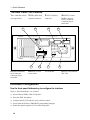
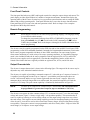
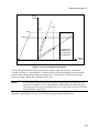
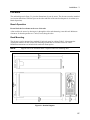
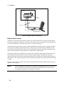
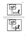
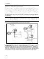
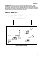
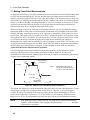
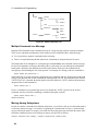
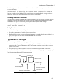
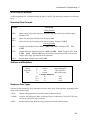
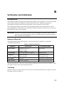
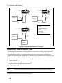
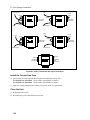
Installation - 3
The load wires must also be of a diameter large enough to avoid excessive voltage drops due to the
impedance of the wires. In general, if the wires are heavy enough to carry the maximum short circuit
current without overheating, excessive voltage drops will not be a problem.
The maximum allowable value of load lead resistance is 4 ohms total (2 ohms per side). This may be
further limited to a lower value, based on peak current loading, by the maximum allowable dc voltage
drop of 8 volts total (4 volts per side) as specified for remote sense operation. To illustrate, for up to 2
amps peak, the maximum allowable resistance is 4 ohms total, resulting in a maximum voltage drop of up
to 8 volts. For 4 amps peak the maximum allowable resistance is 2 ohms total, again resulting in a
maximum allowable voltage drop of up to 8 volts.
In addition to keeping dc resistance low, you also need to minimize the total impedance. For higher slew
rate currents (0.2 to 0.3 amps/µs) and long wiring lengths (10 to 20 ft.) the inductance can have as much
effect as the resistance. To minimize inductance, twist the load leads. The inductance will be on the order
of 0.15 µH/ft if twisted, and 0.4 µH/ft if untwisted. In addition to lowering the inductance, twisting the
leads will reduce noise pick up. If you are using remote sense leads, connect these as a second twisted
pair. Do not twist or bundle them with the load leads.
NOTE:
The use of relays between the dc source and the phone also increases impedance. Low
resistance relays will improve system performance.
Remote Sensing
Turn the unit off before connecting any wires.
With the Remote/Local switch in the Remote position, the dc source regulates the output voltage at
the output terminals on the back of the unit. External sense terminals are available on the back of the unit
that allow the output voltages to be sensed at the load, compensating for impedance losses in the load
wiring. Remote sensing is illustrated in figure 3-2.
NOTE:
For the majority of phone applications, remote sensing is highly recommended. In many
cases, remote sensing must be used to ensure stability and optimize transient response.
The output connector accepts wires sizes from AWG 22 to AWG 12. Disconnect the mating plug to make
your wiring connections. When the sense wire connections are complete, set the Remote/Local switch on
the back of the unit to Remote (switch is out).
29