1
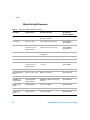
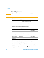
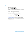
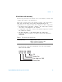
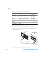
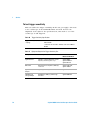
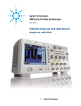
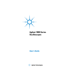
Agilent 1000A Series
Oscilloscopes
Service Guide
s1
Notices
© Agilent Technologies, Inc. 2009, 2013
Warranty
No part of this manual may be reproduced in
any form or by any means (including electronic storage and retrieval or translation
into a foreign language) without prior agreement and written consent from Agilent
Technologies, Inc. as governed by United
States and international copyright laws.
The material contained in this document is provided “as is,” and is subject to being changed, without notice,
in future editions. Further, to the maximum extent permitted by applicable
law, Agilent disclaims all warranties,
either express or implied, with regard
to this manual and any information
contained herein, including but not
limited to the implied warranties of
merchantability and fitness for a particular purpose. Agilent shall not be
liable for errors or for incidental or
consequential damages in connection with the furnishing, use, or performance of this document or of any
information contained herein. Should
Agilent and the user have a separate
written agreement with warranty
terms covering the material in this
document that conflict with these
terms, the warranty terms in the separate agreement shall control.
Manual Part Number
54130-97015
Edition
Third Edition, April 2013
Available in electronic format only
Agilent Technologies, Inc.
1900 Garden of the Gods Road
Colorado Springs, CO 80907 USA
Safety Notices
Technology Licenses
The hardware and/or software described in
this document are furnished under a license
and may be used or copied only in accordance with the terms of such license.
Restricted Rights Legend
U.S. Government Restricted Rights. Software and technical data rights granted to
the federal government include only those
rights customarily provided to end user customers. Agilent provides this customary
commercial license in Software and technical data pursuant to FAR 12.211 (Technical
Data) and 12.212 (Computer Software) and,
for the Department of Defense, DFARS
252.227-7015 (Technical Data - Commercial
Items) and DFARS 227.7202-3 (Rights in
Commercial Computer Software or Computer Software Documentation).
CAUTION
A CAUTION notice denotes a hazard. It calls attention to an operating procedure, practice, or the like
that, if not correctly performed or
adhered to, could result in damage
to the product or loss of important
data. Do not proceed beyond a
CAUTION notice until the indicated
conditions are fully understood and
met.
WA R N I N G
A WARNING notice denotes a
hazard. It calls attention to an
operating procedure, practice, or
the like that, if not correctly performed or adhered to, could result
in personal injury or death. Do not
proceed beyond a WARNING
notice until the indicated conditions are fully understood and
met.
See also Appendix A, “Safety Notices,”
starting on page 41.
Agilent 1000A Series Oscilloscopes Service Guide
Agilent 1000A Series Oscilloscopes—At a Glance
The Agilent 1000A Series oscilloscopes are low- cost portable
digital storage oscilloscopes (DSOs) that deliver these
powerful features:
• Two and four- channel, 60 MHz, 100 MHz, and 200 MHz
bandwidth models.
• Bright 5.7 inch QVGA (320 x 240) TFT color LCD display
and small footprint (to save bench space).
• Up to 2 GSa/s sample rate.
• Up to 20 kpts memory.
• Up to 400 wfms/s refresh rate.
• Automatic voltage and time measurements (22) and
cursor measurements.
• Powerful triggering (edge, pulse width, video, pattern, and
alternate modes) with adjustable sensitivity (to filter
noise and avoid false triggers).
• Math function waveforms: add, subtract, multiply, FFT.
• USB ports (2 host, 1 device) for easy printing, saving, and
sharing of waveforms, setups, screen BMP files, and CSV
data files.
• Internal storage for 10 waveforms and 10 setups.
• Special digital filter and waveform recorder.
• Built- in 6- digit hardware frequency counter.
• Multi- language (11) user interface menus and built- in
help.
Table 1
Agilent 1000A Series Oscilloscope Models
Input Bandwidth (Maximum Sample Rate, Memory)
Channels
200 MHz
(1-2 GSa/s,
10-20 kpts)
100 MHz
(1-2 GSa/s,
10-20 kpts)
60 MHz
(1-2 GSa/s,
10-20 kpts)
4 channel
DSO1024A
DSO1014A
DSO1004A
2 channel
DSO1022A
DSO1012A
DSO1002A
Agilent 1000A Series Oscilloscopes Service Guide
3
In This Book
This guide contains service information for the Agilent
1000A Series oscilloscopes.
1
Service
Describes oscilloscope maintanance, performance testing, and
what to do if your oscilloscope requires service.
4
Agilent 1000A Series Oscilloscopes Service Guide
Contents
Agilent 1000A Series Oscilloscopes—At a Glance
In This Book
Figures
4
7
Tables
1
9
Service
11
Cleaning the Oscilloscope
12
Testing Performance 13
Before Testing Performance 14
To test DC gain accuracy 16
To test analog bandwidth, maximum frequency
To test time scale accuracy 29
To test trigger sensitivity 32
Performance Test Record
Contacting Agilent
Safety Notices
Warnings
39
40
41
41
Safety Symbols
Index
21
35
Returning the Oscilloscope to Agilent for Service
A
3
42
43
Agilent 1000A Series Oscilloscopes Service Guide
5
Contents
6
Agilent 1000A Series Oscilloscopes Service Guide
Figures
Figure 1. Averages Menu Item 17
Figure 2. Connecting Equipment for DC Gain Accuracy Test 18
Figure 3. Vavg Menu Item 19
Figure 4. Connecting Equipment for Maximum Frequency Check Test
Figure 5. Channel 1 Vertical Scale Setting 24
Figure 6. Channel 1 Horizontal Scale Setting 24
Figure 7. Averages Menu Item 25
Figure 8. Signal Generator Waveform 26
Figure 9. Connecting Equipment for Time Scale Accuracy Test 30
Figure 10. Connecting Equipment for Trigger Sensitivity Test 33
Agilent 1000A Series Oscilloscopes Service Guide
23
7
Figures
8
Agilent 1000A Series Oscilloscopes Service Guide
Tables
Table 1. Agilent 1000A Series Oscilloscope Models 3
Table 2. Equipment Required to Perform All Tests 14
Table 3. DC Gain Accuracy Specification 16
Table 4. Equipment Required for DC Gain Accuracy Test 16
Table 5. Analog Bandwidth Specification 21
Table 6. Equipment Required for Analog Bandwidth Test 22
Table 7. Oscilloscope Models and Signal Generator Frequency 27
Table 8. Time Scale Accuracy Specification 29
Table 9. Equipment Required for Time Scale Accuracy Test 30
Table 10. Trigger Sensitivity Specification 32
Table 11. Equipment Required for Trigger Sensitivity Test 32
Table 12. Performance Test Information 35
Table 13. DC Gain Test 35
Table 14. Analog Bandwidth - Maximum Frequency Check 37
Table 15. Time Scale Accuracy 38
Table 16. Trigger Sensitivity 38
Agilent 1000A Series Oscilloscopes Service Guide
9
Tables
10
Agilent 1000A Series Oscilloscopes Service Guide
Agilent 1000A Series Oscilloscopes
Service Guide
1
Service
Cleaning the Oscilloscope 12
Testing Performance 13
Performance Test Record 35
Returning the Oscilloscope to Agilent for Service 39
Contacting Agilent 40
This chapter describes oscilloscope maintanance, performance testing, and
what to do if your oscilloscope requires service.
s1
11
1
Service
Cleaning the Oscilloscope
If the instrument requires cleaning:
1 Remove power from the instrument.
2 Clean the external surfaces of the instrument with a soft cloth
dampened with a mixture of mild detergent and water.
CAUTION
Do not use too much liquid in cleaning the oscilloscope. Water can enter the
oscilloscope’s front panel, damaging sensitive electronic components.
3 Make sure that the instrument is completely dry before reconnecting it
to a power source.
12
Agilent 1000A Series Oscilloscopes Service Guide
Service
1
Testing Performance
This section documents performance test procedures. Performance
verification for the products covered by this manual consists of three main
steps:
• Performing the internal product self- tests to ensure that the
measurement system is functioning properly.
• Calibrating the product.
• Testing the product to ensure that it is performing to specification.
Performance Test
Interval
The procedures in this section may be performed for incoming inspection
and should be performed periodically to verify that the oscilloscope is
operating within specification. The recommended test interval is once per
year or after 2000 hours of operation. Performance should also be tested
after repairs or major upgrades.
Performance Test
Record
A test record form is provided at the end of this section. This record lists
performance tests, test limits and provides space to record test results.
Test Order
The tests in this section may be performed in any order desired. However,
it is recommended to conduct the tests in the order presented in this
manual as this represents an incremental approach to performance
verification. This may be useful if you are attempting to troubleshoot a
suspected problem.
Test Equipment
Lists of equipment needed to conduct each test are provided for each test
procedure. The procedures are written to minimize the number and types
of oscilloscopes and accessories required. The oscilloscopes in these lists
are ones that are currently available for sale by Agilent at the time of
writing this document. In some cases, the test procedures use features
specific to the oscilloscopes in the recommended equipment list. However,
with some modification to the test procedures, oscilloscopes, cables and
accessories that satisfy the critical specifications in these lists may be
substituted for the recommended models with some modification to the
test procedures.
Contact Agilent Technologies (see page 40) for more information about the
Agilent products in these lists.
Agilent 1000A Series Oscilloscopes Service Guide
13
1
Service
Before Testing Performance
Table 2
Equipment Required to Perform All Tests
Description
Required for Test
Critical Specifications
Recommended
Model/Part Numbers
Digital Multimeter
DC Gain Accuracy
DC voltage measurement accuracy better
than ±0.1% of reading
Agilent 34401A
Power Supply
DC Gain Accuracy
0 V to 35 V DC; 10 mV resolution
Agilent E3633A or
Agilent E3634A
Signal Generator
Analog Bandwidth
100 kHz to 1 GHz at 200 mVrms, 0.01 Hz
frequency resolution, jitter: < 2 ps
Agilent 8648A,
Agilent E4400B, or
Agilent N5181A.
Time Scale Accuracy
Trigger Sensitivity
Power Meter
Analog Bandwidth
Agilent E-series with power sensor
compatibility
Agilent E4418B
Power Sensor
Analog Bandwidth
100 kHz to 1 GHz ±3% accuracy
Agilent 8482A
Power Splitter
Analog Bandwidth
Outputs differ by < 0.15 dB
Agilent 11667B
BNC Cable
DC Gain Accuracy (qty 2)
50Ω characteristic impedance, BNC (m)
connectors
Agilent 8120-1840,
Agilent 10503A
Time Scale Accuracy
Trigger Sensitivity
BNC Tee Adapter
DC Gain Accuracy
BNC Tee (m)(f)(f)
Agilent 1250-0781
BNC to Dual Banana
Adapter
DC Gain Accuracy (qty 2)
BNC (f) to dual banana
Agilent 1251-2277
SMA Cable
Analog Bandwidth
SMA (m) to SMA (m) 24 inch
50Ω BNC Feed
Through Adapter
Analog Bandwidth
50Ω BNC (f) to BNC (m) feed through
terminator
Agilent 0960-0301
Trigger Sensitivity
Type-N to SMA
Adapter
Analog Bandwidth
Type-N (m) to SMA (f)
Agilent 1250-1250
SMA to BNC Adapter
Analog Bandwidth
SMA (m) to BNC (m)
Agilent 1250-0831
Type-N to BNC
Adapter
Trigger Sensitivity
Type-N (m) to BNC (f)
Agilent 1250-0780
14
Agilent 1000A Series Oscilloscopes Service Guide
Service
NOTE
1
Let the oscilloscope warm up before testing.
The oscilloscope under test must be warmed up (with the oscilloscope application running)
for at least 30 minutes prior to the start of any performance test.
Calibration
1 Push the [Utility] key on the front panel.
2 In the Utility menu, press Self-Cal.
3 Follow the on- screen instructions.
Agilent 1000A Series Oscilloscopes Service Guide
15
1
Service
To test DC gain accuracy
CAUTION
Ensure that the input voltage to the oscilloscope never exceeds 300 Vrms.
Table 3
DC Gain Accuracy Specification
DC Gain Accuracy
2 mV/div to 5 mV/div: ±4.0% full scale
10 mV/div to 5 V/div: ±3.0% full scale
Full scale is defined as 8 vertical divisions. The major scale settings are 2 mV, 5 mV, 10 mV, 20 mV,
50 mV, 100 mV, 200 mV, 500 mV, 1 V, 2 V, and 5 V.
Table 4
Equipment Required for DC Gain Accuracy Test
Description
Critical Specifications
Recommended
Model/Part Numbers
Power Supply
0 V to 35 V DC; 10 mV resolution
Agilent E3633A or
Agilent E3634A
Digital Multimeter
DC voltage measurement accuracy better
than ±0.1% of reading
Agilent 34401A
BNC Cable (qty 2)
50Ω characteristic impedance, BNC (m)
connectors
Agilent 8120-1840,
Agilent 10503A
BNC Tee Adapter
BNC Tee (m)(f)(f)
Agilent 1250-0781
BNC to Dual Banana
Adapter (qty 2)
BNC (f) to dual banana
Agilent 1251-2277
1 Disconnect all cables from the oscilloscope channel inputs.
2 Press the [Default Setup] front panel key.
3 Press the [Acquire] front panel key.
4 In the Acquire menu, press the Acquisition softkey until “Average”
appears.
5 Press the Averages softkey and turn the
appears.
16
entry knob until “256”
Agilent 1000A Series Oscilloscopes Service Guide
Service
Figure 1
1
Averages Menu Item
6 Set the channel 1 probe attenuation to 1X.
7 Set the channel 1 vertical sensitivity value to 2 mV/div.
8 Set the power supply to +6 mV.
9 Connect the equipment as shown in Figure 2.
Agilent 1000A Series Oscilloscopes Service Guide
17
1
Service
Oscilloscope
Power Supply
Digital Multimeter
BNC tee
BNC (f)
to dual
banana
Figure 2
Connecting Equipment for DC Gain Accuracy Test
10 Press [Measure].
11 Press the Voltage softkey.
12 Turn the
below.
18
entry knob to select the Vavg measurement as shown
Agilent 1000A Series Oscilloscopes Service Guide
Service
1
Vavg
measurement
Figure 3
Vavg Menu Item
13 For each of channel 1’s vertical sensitivities in the DC Gain Test section
of the “Performance Test Record” on page 35:
a For the positive (+) power supply setting:
i Record the DMM voltage reading as VDMM+.
ii Record the oscilloscope Vavg reading as VScope+.
b For the negative (- ) power supply setting:
i Record the DMM voltage reading as VDMM- .
ii Record the oscilloscope Vavg reading as VScope- .
c Calculate the DC Gain using the following expression and record this
value in the DC Gain Test section of the Performance Test Record:
ΔV out V scope+ – V scopeDCGain = --------------- = -------------------------------------------ΔV in V DMM+ – V DMM14 Repeat step 15 through step 23 for channel 2 on two- channel
oscilloscope models or for channels 2, 3, and 4 on four- channel models.
15 Set the power supply voltage to +6 mV.
16 Move the BNC cable from the previously tested channel to the channel
you are currently testing.
Agilent 1000A Series Oscilloscopes Service Guide
19
1
Service
17 Press the [Default Setup] front panel key.
18 Set the channel’s probe attenuation to 1X.
19 Set the channel’s vertical sensitivity value to 2 mV/div.
20 Press [Measure].
21 Press the Voltage softkey.
22 Turn the
entry knob to select the Vavg measurement.
23 For each of the channel’s vertical sensitivities in the DC Gain Test
section of the “Performance Test Record” on page 35:
a For the positive (+) power supply setting:
i Record the DMM voltage reading as VDMM+.
ii Record the oscilloscope Vavg reading as VScope+.
b For the negative (- ) power supply setting:
i Record the DMM voltage reading as VDMM- .
ii Record the oscilloscope Vavg reading as VScope- .
c Calculate the DC Gain using the following expression and record this
value in the DC Gain Test section of the Performance Test Record:
ΔV out
DCGain = --------------- =
ΔV in
20
V scope+ – V scope-------------------------------------------V DMM+ – V DMM-
Agilent 1000A Series Oscilloscopes Service Guide
Service
1
To test analog bandwidth, maximum frequency
CAUTION
NOTE
Ensure that the input voltage to the oscilloscope never exceeds 300 Vrms.
This procedure is the only acceptable method for testing the bandwidth of a 1000A Series
oscilloscope.
Table 5
Analog Bandwidth Specification
Analog Bandwidth (-3 dB)
DSO102xA
200 MHz
DSO101xA
100 MHz
DSO100xA
60 MHz
Agilent 1000A Series Oscilloscopes Service Guide
21
1
Service
Table 6
22
Equipment Required for Analog Bandwidth Test
Description
Critical Specifications
Recommended
Model/Part Numbers
Signal Generator
100 kHz to 1 GHz at 200 mVrms, 0.01 Hz
frequency resolution, jitter: < 2 ps
Agilent 8648A,
Agilent E4400B, or
Agilent N5181A.
Power Meter
Agilent E-series with power sensor
compatibility
Agilent E4418B
Power Sensor
100 kHz to 1 GHz ±3% accuracy
Agilent 8482A
Power Splitter
Outputs differ by < 0.15 dB
Agilent 11667B
SMA Cable
SMA (m) to SMA (m) 24 inch
50Ω BNC Feed
Through Adapter
50Ω BNC (f) to BNC (m) feed through
terminator
Agilent 0960-0301
Type-N to SMA
Adapter
Type-N (m) to SMA (f)
Agilent 1250-1250
SMA to BNC Adapter
SMA (m) to BNC (m)
Agilent 1250-0831
Agilent 1000A Series Oscilloscopes Service Guide
Service
1
1 Connect the equipment as shown in Figure 4.
Power Meter
E4418B
Oscilloscope
Signal Generator
50W feed
through
Power splitter
11667B
Power sensor
cable
SMA to BNC adapter
Power sensor
8482A
Figure 4
SMA cable
Type-N (m) to
SMA (f) adapter
Connecting Equipment for Maximum Frequency Check Test
2 Preset and calibrate the power meter according to the instructions
found in the power meter manual.
3 Set up the Power Meter to display measurements in units of Watts.
4 Press the [Default Setup] front panel key.
5 Press the [Auto-Scale] front panel key.
6 Set the channel 1 probe attenuation to 1X.
7 Set the channel 1 vertical scale to 200 mV/div.
Agilent 1000A Series Oscilloscopes Service Guide
23
1
Service
Figure 5
Channel 1 Vertical Scale Setting
8 Set the horizontal scale to 500 ns/div.
Figure 6
24
Channel 1 Horizontal Scale Setting
Agilent 1000A Series Oscilloscopes Service Guide
Service
1
9 Press [Acquire].
10 Press the Acquisition softkey until “Average” appears.
11 Press Average and turn the
Figure 7
entry knob until “8” appears.
Averages Menu Item
12 Press [Measure].
13 Press the Voltage softkey.
14 Turn the
entry knob to select the Vpp menu item.
15 Set the signal generator to a 1 MHz sine wave with a peak- to- peak
amplitude of about 6 divisions as it appears on the oscilloscope screen.
Agilent 1000A Series Oscilloscopes Service Guide
25
1
Service
Vpp reading
Figure 8
Signal Generator Waveform
16 Using the Vpp reading, calculate the Vrms value using the following
expression and record it in the “Performance Test Record” on page 35:
Vpp 1MHz
Vout 1MHz = ----------------------2 2
For example, if Vpp = 1.20 V:
1.20 1.20
Vout 1MHz = ---------- = ------------- = 424 mV
2 2 2.828
17 Using the power meter reading, convert this measurement to Volts RMS
using the expression and record it in the “Performance Test Record” on
page 35:
Vin1MHz =
P meas × 50Ω
For example, if Pmeas = 3.65 mW:
Vin1MHz =
26
3.65 mW × 50Ω = 427 mV
Agilent 1000A Series Oscilloscopes Service Guide
Service
1
18 Calculate the reference gain as follows:
Vout 1MHz
Gain 1MHz = ---------------------------Vin 1MHz
Record this value in the Calculated Gain @ 1 MHz column of the
“Performance Test Record” on page 35.
19 Change the signal generator frequency to the value for the model being
tested as shown in the table below.
Table 7
Oscilloscope Models and Signal Generator Frequency
Setting
Model
DSO102xA
DSO101xA
DSO100xA
Frequency
200 MHz
100 MHz
60 MHz
Time Base
2 ns/div
5 ns/div
10 ns/div
20 Change the oscilloscope time base to the value for the model being tests
as shown in the table above.
21 Using the Vpp reading, calculate the Vrms value using the following
expression and record it in the “Performance Test Record” on page 35:
Vpp max
Vout max = ------------------2 2
For example, if Vpp = 1.24 V:
1.05 1.05
Vout max = ---------- = ------------- = 371 mV
2 2 2.828
22 Using the power meter reading, convert this measurement to Volts RMS
using the expression and record it in the “Performance Test Record” on
page 35:
Vinmax =
P meas × 50Ω
Agilent 1000A Series Oscilloscopes Service Guide
27
1
Service
For example, if Pmeas = 3.65 mW:
Vinmax =
3.65 mW × 50Ω = 427 mV
23 Calculate the gain at the maximum frequency using the expression and
record it in the “Performance Test Record” on page 35:
Gain max = 20 log 10
( Vout max ) ⁄ ( Vin max )
---------------------------------------------------------Gain 1MHz
For example, if (Vout @ Max Frequency) = 371 mV, (Vin @ Max
Frequency) = 427 mV and Gain @ 1 MHz = 0.993, then:
371 mV ⁄ 427 mV
Gain Max Freq = 20 log10 -------------------------------------------- = -1.16 dB
0.993
Record this value in the Calculated Gain @Max Freq column in the
Analog Bandwidth - Maximum Frequency Check section of the
“Performance Test Record” on page 35. To pass this test, this value
must be greater than - 3.0 dB.
24 For the remaining channels, move the power splitter to the channel and
repeat steps 4 through 23.
28
Agilent 1000A Series Oscilloscopes Service Guide
Service
1
To test time scale accuracy
In this test you measure the absolute error of the timebase oscillator and
compare the results to the specification.
Time scale accuracy refers to the absolute accuracy of the oscilloscope's
time scale. Because time scale accuracy depends directly on the
specifications of a crystal oscillator, it is comprised of these components:
• An initial accuracy component — applies to the oscilloscope's accuracy
on the date of its shipment to the customer.
• A temperature component — refers to the ambient temperaure in which
the oscilloscope operates.
• An aging component — scales linearly from the oscilloscope's
manufacture date and adds to the initial accuracy and temperature
components.
Table 8
Time Scale Accuracy Specification
Time Scale Accuracy
±50 ppm from 0 °C to 30 °C
±50 ppm + 2 ppm per °C from 30 °C to 45 °C
+ 5 ppm * (years since manufacture)
You can get the “years since manufacture” from the serial number,
which is in this format:
CN XX XX XXXX
ID#
Week in Year
Year Code (year - 1960)
Country Code
Agilent 1000A Series Oscilloscopes Service Guide
29
1
Service
Table 9
Equipment Required for Time Scale Accuracy Test
Description
Critical Specifications
Recommended
Model/Part Numbers
Signal Generator
100 kHz - 1 GHz, 0.01 Hz frequency resolution,
jitter: < 2 ps
Agilent N5181A,
Agilent E4400B, or
Agilent 8648A
BNC Cable
50Ω characteristic impedance, BNC (m)
connectors
Agilent 8120-1840,
Agilent 10503A
Type-N to BNC
Adapter
Type-N (m) to BNC (f)
Agilent 1250-0780
50Ω BNC Feed
Through Adapter
50Ω BNC (f) to BNC (m) feed through
terminator
Agilent 0960-0301
1 Set up the signal generator:
a Set the output to 10 MHz, approximately 1 Vpp sine wave.
2 Connect the output of the signal generator to oscilloscope channel 1
using the BNC cable.
Oscilloscope
Signal Generator
50W feed
through
BNC cable
Type-N (m) to
BNC (f) adapter
Figure 9
30
Connecting Equipment for Time Scale Accuracy Test
Agilent 1000A Series Oscilloscopes Service Guide
Service
1
3 Set up the oscilloscope:
a Press [Auto-Scale].
b Set the oscilloscope Channel 1 probe attenuation to 1X.
c Set the oscilloscope Channel 1 vertical sensitivity to 200 mV/div.
d Set the oscilloscope horizontal sweep speed control to 5 ns/div.
e Adjust the intensity to get a sharp, clear trace.
f Adjust the oscilloscope’s trigger level so that the rising edge of the
waveform at the center of the screen is located where the center
horizontal and vertical grid lines cross (center screen).
g Ensure the horizontal position control is set to 0.0 seconds.
4 Make the measurement.
a Set oscilloscope horizontal sweep speed control to 1 ms/div.
b Set horizontal position control to +1 ms (rotate control
counter- clockwise).
c Set the oscilloscope horizontal sweep speed control to 10 ns/div.
d Turn on the zoomed time base by pressing the [Menu/Zoom] key
followed by the Zoom softkey in the Horizontal menu.
e Record the number of nanoseconds from where the rising edge
crosses the center horizontal grid line to the center vertical grid line.
The number of nanoseconds is equivalent to the time scale error in
ppm.
f Record the result and compare it to the limits in the “Performance
Test Record” on page 35.
Agilent 1000A Series Oscilloscopes Service Guide
31
1
Service
To test trigger sensitivity
This test verifies the trigger sensitivity. In this test, you apply a sine wave
to the oscilloscope at the bandwidth limits. You then decrease the
amplitude of the signal to the specified levels, and check to see if the
oscilloscope is still triggered.
Table 10
Trigger Sensitivity Specification
Trigger sensitivity Ch 1, 2, 3, 4 (DC
coupling):
≥ 5 mV/div: 1 div from DC to 10 MHz, 1.5 div from 10 MHz to
full bandwidth
< 5 mV/div: 1 div from DC to 10 MHz, 1.5 div from 10 MHz to
20 MHz
Table 11
32
Equipment Required for Trigger Sensitivity Test
Description
Critical Specifications
Recommended
Model/Part Numbers
Signal Generator
100 kHz to 1 GHz at 200 mVrms, 0.01 Hz
frequency resolution, jitter: < 2 ps
Agilent 8648A,
Agilent E4400B, or
Agilent N5181A.
BNC Cable
50Ω characteristic impedance, BNC (m)
connectors
Agilent 8120-1840,
Agilent 10503A
Type-N to BNC
Adapter
Type-N (m) to BNC (f)
Agilent 1250-0780
50Ω BNC Feed
Through Adapter
50Ω BNC (f) to BNC (m) feed through
terminator
Agilent 0960-0301
Agilent 1000A Series Oscilloscopes Service Guide
Service
1
1 Connect the equipment (see Figure 10).
a Connect the signal generator output to the oscilloscope channel 1
input.
Oscilloscope
Signal Generator
50W feed
through
BNC cable
Type-N (m) to
BNC (f) adapter
Figure 10
Connecting Equipment for Trigger Sensitivity Test
2 Verify the trigger sensitivity when the vertical scale is ≥ 5 mV/div.
For each of the bandwidth boundaries (maximum bandwidth and
10 MHz):
a Press the [Default Setup] key.
b Set the output frequency of the signal generator to the bandwidth
boundary and set the amplitude to about 10 mVpp.
c Press the [Auto-Scale] key.
d Set the horizontal scale so that a few cycles of the waveform are
displayed.
e Set the input channel’s probe attenuation to 1X.
f Set the input channel’s vertical scale to 5 mV/div.
g Decrease the amplitude from the signal generator to the specified
vertical division (1.5 div at maximum bandwith or 1 div at 10 MHz).
Agilent 1000A Series Oscilloscopes Service Guide
33
1
Service
The trigger is stable when the displayed waveform is stable. If the
trigger is not stable, try adjusting the trigger level. If adjusting the
trigger level makes the trigger stable, the test still passes.
h Record the result as Pass or Fail in the “Performance Test Record”
on page 35.
Repeat these steps for the remaining oscilloscope channels.
3 Verify the trigger sensitivity when the vertical scale is < 5 mV/div.
For each of the bandwidth boundaries (20 MHz and 10 MHz):
a Press the [Default Setup] key.
b Set the output frequency of the signal generator to the bandwidth
boundary and set the amplitude to about 10 mVpp.
c Press the [Auto-Scale] key.
d Set the horizontal scale so that a few cycles of the waveform are
displayed.
e Set the input channel’s probe attenuation to 1X.
f Set the input channel’s vertical scale to 2 mV/div.
g Decrease the amplitude from the signal generator to the specified
vertical division (1.5 div at 20 MHz or 1 div at 10 MHz).
The trigger is stable when the displayed waveform is stable. If the
trigger is not stable, try adjusting the trigger level. If adjusting the
trigger level makes the trigger stable, the test still passes.
h Record the result as Pass or Fail in the “Performance Test Record”
on page 35.
Repeat these steps for the remaining oscilloscope channels.
34
Agilent 1000A Series Oscilloscopes Service Guide
Service
1
Performance Test Record
Table 12
Performance Test Information
Serial No. ______________________________________
Test by _____________________________
Test Interval ____________________________________
Work Order No. ______________________
Recommended Next Testing ________________________
Temperature ____________
Table 13
DC Gain Test
Vertical
Sensitivity
Power
Supply
Setting
VDMM+
VDMM-
VScope+
VScope-
Calculated
DC Gain
Offset Gain Test
Limits
Channel 1
2 mV/div
±6 mV
+0.96 to +1.04
5 mV/div
±15 mV
+0.96 to +1.04
10 mV/div
±30 mV
+0.97 to +1.03
20 mV/div
±60 mV
+0.97 to +1.03
50 mV/div
±150 mV
+0.97 to +1.03
100 mV/div
±300 mV
+0.97 to +1.03
200 mV/div
±600 mV
+0.97 to +1.03
500 mV/div
±1.5 V
+0.97 to +1.03
1 V/div
±3.0 V
+0.97 to +1.03
2 V/div
±6.0 V
+0.97 to +1.03
5 V/div
±15.0 V
+0.97 to +1.03
Agilent 1000A Series Oscilloscopes Service Guide
35
1
Service
Table 13
DC Gain Test (continued)
Vertical
Sensitivity
Power
Supply
Setting
VDMM+
VDMM-
VScope+
VScope-
Calculated
DC Gain
Offset Gain Test
Limits
Channel 2
2 mV/div
±6 mV
+0.96 to +1.04
5 mV/div
±15 mV
+0.96 to +1.04
10 mV/div
±30 mV
+0.97 to +1.03
20 mV/div
±60 mV
+0.97 to +1.03
50 mV/div
±150 mV
+0.97 to +1.03
100 mV/div
±300 mV
+0.97 to +1.03
200 mV/div
±600 mV
+0.97 to +1.03
500 mV/div
±1.5 V
+0.97 to +1.03
1 V/div
±3.0 V
+0.97 to +1.03
2 V/div
±6.0 V
+0.97 to +1.03
5 V/div
±15.0 V
+0.97 to +1.03
Channel 3
36
Agilent 1000A Series Oscilloscopes Service Guide
Service
Table 13
1
DC Gain Test (continued)
Vertical
Sensitivity
Power
Supply
Setting
VDMM+
VDMM-
VScope+
VScope-
Calculated
DC Gain
Offset Gain Test
Limits
Channel 4
2 mV/div
±6 mV
+0.96 to +1.04
5 mV/div
±15 mV
+0.96 to +1.04
10 mV/div
±30 mV
+0.97 to +1.03
20 mV/div
±60 mV
+0.97 to +1.03
50 mV/div
±150 mV
+0.97 to +1.03
100 mV/div
±300 mV
+0.97 to +1.03
200 mV/div
±600 mV
+0.97 to +1.03
500 mV/div
±1.5 V
+0.97 to +1.03
1 V/div
±3.0 V
+0.97 to +1.03
2 V/div
±6.0 V
+0.97 to +1.03
5 V/div
±15.0 V
+0.97 to +1.03
Table 14
Analog Bandwidth - Maximum Frequency Check
Vin @ 1 MHz
Vout @
1 MHz
Calculated Gain
@ 1 MHz (Test
Limit = greater
than -3 dB)
Vin @ Max
Freq
Vout @ Max
Freq
Calculated Gain
@ Max Freq
(Test Limit =
greater than -3
dB)
Channel 1
Channel 2
Channel 3
Channel 4
Max frequency: DSO102xA = 200 MHz, DSO101xA = 100 MHz, DSO100xA = 60 MHz
Agilent 1000A Series Oscilloscopes Service Guide
37
1
Service
Table 15
Time Scale Accuracy
Limits
Measured time scale error (ppm)
Pass/Fail
±50 ppm from 0 °C to 30 °C
±50 ppm + 2 ppm per °C from 30 °C to 45 °C
+ 5 ppm * (years since manufacture)
Table 16
Trigger Sensitivity
Test Limits
Ch1
Ch2
C3
Ch4
≥ 5 mV/div: 1.5 division at maximum bandwidth
≥ 5 mV/div: 1 division at 10 MHz
< 5 mV/div: 1.5 division at 20 MHz
< 5 mV/div: 1 division at 10 MHz
38
Agilent 1000A Series Oscilloscopes Service Guide
Service
1
Returning the Oscilloscope to Agilent for Service
Before shipping the oscilloscope to Agilent Technologies, contact your
nearest Agilent Technologies oscilloscope Support Center (or Agilent
Technologies Service Center if outside the United States) for additional
details.
1 Write the following information on a tag and attach it to the
oscilloscope.
• Name and address of owner.
• Oscilloscope model number.
• Oscilloscope serial number.
• Description of the service required or failure indications.
2 Remove all accessories from the oscilloscope.
Accessories include all cables. Do not include accessories unless they
are associated with the failure symptoms.
3 Protect the oscilloscope by wrapping it in plastic or heavy paper.
4 Pack the oscilloscope in foam or other shock absorbing material and
place it in a strong shipping container.
You can use the original shipping materials or order materials from an
Agilent Technologies Sales Office. If neither are available, place 8 to
10 cm (3 to 4 inches) of shock- absorbing material around the
oscilloscope and place it in a box that does not allow movement during
shipping.
5 Seal the shipping container securely.
6 Mark the shipping container as FRAGILE.
In any correspondence, refer to oscilloscope by model number and full
serial number.
Agilent 1000A Series Oscilloscopes Service Guide
39
1
Service
Contacting Agilent
Information on contacting Agilent Technologies can be found at
www.agilent.com/find/contactus.
40
Agilent 1000A Series Oscilloscopes Service Guide
Agilent 1000A Series Oscilloscopes
Service Guide
A
Safety Notices
Warnings 41
Safety Symbols 42
This apparatus has been designed and tested in accordance with IEC
Publication 1010, Safety Requirements for Measuring Apparatus, and has
been supplied in a safe condition. This is a Safety Class I instrument
(provided with terminal for protective earthing). Before applying power,
verify that the correct safety precautions are taken (see the following
warnings). In addition, note the external markings on the instrument that
are described under "Safety Symbols."
Warnings
• Before turning on the instrument, you must connect the protective
earth terminal of the instrument to the protective conductor of the
(mains) power cord. The mains plug shall only be inserted in a socket
outlet provided with a protective earth contact. You must not negate the
protective action by using an extension cord (power cable) without a
protective conductor (grounding). Grounding one conductor of a
two- conductor outlet is not sufficient protection.
• Only fuses with the required rated current, voltage, and specified type
(normal blow, time delay, etc.) should be used. Do not use repaired
fuses or short- circuited fuse holders. To do so could cause a shock or
fire hazard.
• If you energize this instrument by an auto transformer (for voltage
reduction or mains isolation), the common terminal must be connected
to the earth terminal of the power source.
s1
41
A
Safety Notices
• Whenever it is likely that the ground protection is impaired, you must
make the instrument inoperative and secure it against any unintended
operation.
• Service instructions are for trained service personnel. To avoid
dangerous electric shock, do not perform any service unless qualified to
do so. Do not attempt internal service or adjustment unless another
person, capable of rendering first aid and resuscitation, is present.
• Do not install substitute parts or perform any unauthorized
modification to the instrument.
• Capacitors inside the instrument may retain a charge even if the
instrument is disconnected from its source of supply.
• Do not operate the instrument in the presence of flammable gasses or
fumes. Operation of any electrical instrument in such an environment
constitutes a definite safety hazard.
• Do not use the instrument in a manner not specified by the
manufacturer.
Safety Symbols
!
Instruction manual symbol: the product is marked with this symbol
when it is necessary for you to refer to the instruction manual in
order to protect against damage to the product.
Hazardous voltage symbol.
Earth terminal symbol: Used to indicate a circuit common connected
to grounded chassis.
42
Agilent 1000A Series Oscilloscopes Service Guide
Index
A
L
V
analog bandwidth - maximum frequency
check, 21
at a glance, 3
LCD display, 3
voltage measurements, 3
M
W
B
warnings, 41
waveforms, recording/playing-back, 3
built-in help, 3
math function waveforms, 3
memory, 3
model number, 39
C
P
calibration, 15
cleaning the oscilloscope, 12
counter, frequency, 3
cursor measurements, 3
performance test interval, 13
performance test record, 13
performance, testing, 13
D
DC gain accuracy test, 16
digital filter, 3
E
equipment for performance testing, 13
F
frequency counter, hardware, 3
H
hardware frequency counter, 3
I
input voltage, 16, 21
internal storage, 3
R
refresh rate, 3
S
safety
notices, 41
symbols, 42
sample rate, 3
serial number, 39
symbols, safety, 42
T
test equipment, 13
testing performance, 13
time measurements, 3
triggering, 3
U
USB ports, 3
Agilent 1000A Series Oscilloscopes Service Guide
43
Index
44
Agilent 1000A Series Oscilloscopes Service Guide
www.agilent.com
© Agilent Technologies, Inc. 2009, 2013
Available in electronic format only
Third Edition, April 2013
*54130-97015*
54130-97015
s1