1
To our customers,
Old Company Name in Catalogs and Other Documents
On April 1st, 2010, NEC Electronics Corporation merged with Renesas Technology
Corporation, and Renesas Electronics Corporation took over all the business of both
companies. Therefore, although the old company name remains in this document, it is a valid
Renesas Electronics document. We appreciate your understanding.
Renesas Electronics website: http://www.renesas.com
April 1st, 2010
Renesas Electronics Corporation
Issued by: Renesas Electronics Corporation (http://www.renesas.com)
Send any inquiries to http://www.renesas.com/inquiry.
Notice
1.
2.
3.
4.
5.
6.
7.
All information included in this document is current as of the date this document is issued. Such information, however, is
subject to change without any prior notice. Before purchasing or using any Renesas Electronics products listed herein, please
confirm the latest product information with a Renesas Electronics sales office. Also, please pay regular and careful attention to
additional and different information to be disclosed by Renesas Electronics such as that disclosed through our website.
Renesas Electronics does not assume any liability for infringement of patents, copyrights, or other intellectual property rights
of third parties by or arising from the use of Renesas Electronics products or technical information described in this document.
No license, express, implied or otherwise, is granted hereby under any patents, copyrights or other intellectual property rights
of Renesas Electronics or others.
You should not alter, modify, copy, or otherwise misappropriate any Renesas Electronics product, whether in whole or in part.
Descriptions of circuits, software and other related information in this document are provided only to illustrate the operation of
semiconductor products and application examples. You are fully responsible for the incorporation of these circuits, software,
and information in the design of your equipment. Renesas Electronics assumes no responsibility for any losses incurred by
you or third parties arising from the use of these circuits, software, or information.
When exporting the products or technology described in this document, you should comply with the applicable export control
laws and regulations and follow the procedures required by such laws and regulations. You should not use Renesas
Electronics products or the technology described in this document for any purpose relating to military applications or use by
the military, including but not limited to the development of weapons of mass destruction. Renesas Electronics products and
technology may not be used for or incorporated into any products or systems whose manufacture, use, or sale is prohibited
under any applicable domestic or foreign laws or regulations.
Renesas Electronics has used reasonable care in preparing the information included in this document, but Renesas Electronics
does not warrant that such information is error free. Renesas Electronics assumes no liability whatsoever for any damages
incurred by you resulting from errors in or omissions from the information included herein.
Renesas Electronics products are classified according to the following three quality grades: “Standard”, “High Quality”, and
“Specific”. The recommended applications for each Renesas Electronics product depends on the product’s quality grade, as
indicated below. You must check the quality grade of each Renesas Electronics product before using it in a particular
application. You may not use any Renesas Electronics product for any application categorized as “Specific” without the prior
written consent of Renesas Electronics. Further, you may not use any Renesas Electronics product for any application for
which it is not intended without the prior written consent of Renesas Electronics. Renesas Electronics shall not be in any way
liable for any damages or losses incurred by you or third parties arising from the use of any Renesas Electronics product for an
application categorized as “Specific” or for which the product is not intended where you have failed to obtain the prior written
consent of Renesas Electronics. The quality grade of each Renesas Electronics product is “Standard” unless otherwise
expressly specified in a Renesas Electronics data sheets or data books, etc.
“Standard”:
8.
9.
10.
11.
12.
Computers; office equipment; communications equipment; test and measurement equipment; audio and visual
equipment; home electronic appliances; machine tools; personal electronic equipment; and industrial robots.
“High Quality”: Transportation equipment (automobiles, trains, ships, etc.); traffic control systems; anti-disaster systems; anticrime systems; safety equipment; and medical equipment not specifically designed for life support.
“Specific”:
Aircraft; aerospace equipment; submersible repeaters; nuclear reactor control systems; medical equipment or
systems for life support (e.g. artificial life support devices or systems), surgical implantations, or healthcare
intervention (e.g. excision, etc.), and any other applications or purposes that pose a direct threat to human life.
You should use the Renesas Electronics products described in this document within the range specified by Renesas Electronics,
especially with respect to the maximum rating, operating supply voltage range, movement power voltage range, heat radiation
characteristics, installation and other product characteristics. Renesas Electronics shall have no liability for malfunctions or
damages arising out of the use of Renesas Electronics products beyond such specified ranges.
Although Renesas Electronics endeavors to improve the quality and reliability of its products, semiconductor products have
specific characteristics such as the occurrence of failure at a certain rate and malfunctions under certain use conditions. Further,
Renesas Electronics products are not subject to radiation resistance design. Please be sure to implement safety measures to
guard them against the possibility of physical injury, and injury or damage caused by fire in the event of the failure of a
Renesas Electronics product, such as safety design for hardware and software including but not limited to redundancy, fire
control and malfunction prevention, appropriate treatment for aging degradation or any other appropriate measures. Because
the evaluation of microcomputer software alone is very difficult, please evaluate the safety of the final products or system
manufactured by you.
Please contact a Renesas Electronics sales office for details as to environmental matters such as the environmental
compatibility of each Renesas Electronics product. Please use Renesas Electronics products in compliance with all applicable
laws and regulations that regulate the inclusion or use of controlled substances, including without limitation, the EU RoHS
Directive. Renesas Electronics assumes no liability for damages or losses occurring as a result of your noncompliance with
applicable laws and regulations.
This document may not be reproduced or duplicated, in any form, in whole or in part, without prior written consent of Renesas
Electronics.
Please contact a Renesas Electronics sales office if you have any questions regarding the information contained in this
document or Renesas Electronics products, or if you have any other inquiries.
(Note 1) “Renesas Electronics” as used in this document means Renesas Electronics Corporation and also includes its majorityowned subsidiaries.
(Note 2) “Renesas Electronics product(s)” means any product developed or manufactured by or for Renesas Electronics.
To all our customers
Regarding the change of names mentioned in the document, such as Mitsubishi
Electric and Mitsubishi XX, to Renesas Technology Corp.
The semiconductor operations of Hitachi and Mitsubishi Electric were transferred to Renesas
Technology Corporation on April 1st 2003. These operations include microcomputer, logic, analog
and discrete devices, and memory chips other than DRAMs (flash memory, SRAMs etc.)
Accordingly, although Mitsubishi Electric, Mitsubishi Electric Corporation, Mitsubishi
Semiconductors, and other Mitsubishi brand names are mentioned in the document, these names
have in fact all been changed to Renesas Technology Corp. Thank you for your understanding.
Except for our corporate trademark, logo and corporate statement, no changes whatsoever have been
made to the contents of the document, and these changes do not constitute any alteration to the
contents of the document itself.
Note : Mitsubishi Electric will continue the business operations of high frequency & optical devices
and power devices.
Renesas Technology Corp.
Customer Support Dept.
April 1, 2003
Usage Notes Reference Book
16
M16C/62
(M16C/62A, M16C/62M) Group
Usage Notes Reference Book
Renesas 16-BIT SINGLE-CHIP MICROCOMPUTER
M16C FAMILY / M16C/60 SERIES
All information contained in these materials, including products and product specifications,
represents information on the product at the time of publication and is subject to change by
Renesas Electronics Corp. without notice. Please review the latest information published by
Renesas Electronics Corp. through various means, including the Renesas Electronics Corp.
website (http://www.renesas.com).
2001.10
Keep safety first in your circuit designs!
●
Mitsubishi Electric Corporation puts the maximum effort into making semiconductor
products better and more reliable, but there is always the possibility that trouble may
occur with them. Trouble with semiconductors may lead to personal injury, fire or
property damage. Remember to give due consideration to safety when making your
circuit designs, with appropriate measures such as (i) placement of substitutive,
auxiliary circuits, (ii) use of non-flammable material or (iii) prevention against any
malfunction or mishap.
Notes regarding these materials
●
●
●
●
●
●
●
●
These materials are intended as a reference to assist our customers in the selection
of the Mitsubishi semiconductor product best suited to the customer's application;
they do not convey any license under any intellectual property rights, or any other
rights, belonging to Mitsubishi Electric Corporation or a third party.
Mitsubishi Electric Corporation assumes no responsibility for any damage, or
infringement of any third-party's rights, originating in the use of any product data,
diagrams, charts, programs, algorithms, or circuit application examples contained in
these materials.
All information contained in these materials, including product data, diagrams, charts,
programs and algorithms represents information on products at the time of publication
of these materials, and are subject to change by Mitsubishi Electric Corporation
without notice due to product improvements or other reasons. It is therefore
recommended that customers contact Mitsubishi Electric Corporation or an authorized
Mitsubishi Semiconductor product distributor for the latest product information before
purchasing a product listed herein.
The information described here may contain technical inaccuracies or typographical
errors. Mitsubishi Electric Corporation assumes no responsibility for any damage,
liability, or other loss rising from these inaccuracies or errors.
Please also pay attention to information published by Mitsubishi Electric Corporation
by various means, including the Mitsubishi Semiconductor home page (http://
www.mitsubishichips.com).
When using any or all of the information contained in these materials, including
product data, diagrams, charts, programs, and algorithms, please be sure to evaluate
all information as a total system before making a final decision on the applicability of
the information and products. Mitsubishi Electric Corporation assumes no
responsibility for any damage, liability or other loss resulting from the information
contained herein.
Mitsubishi Electric Corporation semiconductors are not designed or manufactured
for use in a device or system that is used under circumstances in which human life is
potentially at stake. Please contact Mitsubishi Electric Corporation or an authorized
Mitsubishi Semiconductor product distributor when considering the use of a product
contained herein for any specific purposes, such as apparatus or systems for
transportation, vehicular, medical, aerospace, nuclear, or undersea repeater use.
The prior written approval of Mitsubishi Electric Corporation is necessary to reprint
or reproduce in whole or in part these materials.
If these products or technologies are subject to the Japanese export control
restrictions, they must be exported under a license from the Japanese government
and cannot be imported into a country other than the approved destination.
Any diversion or reexport contrary to the export control laws and regulations of Japan
and/or the country of destination is prohibited.
Please contact Mitsubishi Electric Corporation or an authorized Mitsubishi Semicon
ductor product distributor for further details on these materials or the products con
tained therein.
Preface
This book describes the M16C/62 (M16C/62A,
M16C/62M) group's precautions for use, which
contains paragraphs describing precautions of
the user's manual and technical news relevant
to these paragraphs. Please refer to this book
when developing your systems. However, all of
precautions are not contained in this book,
please perform sufficient evaluation under systems development.
Mitsubishi microcomputers
M16C / 62A Group
Precautions for Interrupts
SINGLE-CHIP 16-BIT CMOS MICROCOMPUTER
Precautions for Interrupts
(1) Reading address 0000016
• When maskable interrupt is occurred, CPU reads the interrupt information (the interrupt number and
interrupt request level) in the interrupt sequence.
The interrupt request bit of the certain interrupt written in address 0000016 will then be set to “0”.
Even if the address 0000016 is read out by software, “0” is set to the enabled highest priority interrupt
source request bit. Therefore interrupt can be canceled and unexpected interrupt can occur.
Do not read address 0000016 by software.
(2) Setting the stack pointer
• The value of the stack pointer immediately after reset is initialized to 000016. Accepting an interrupt
before setting a value in the stack pointer may become a factor of runaway. Be sure to set a value in
_______
the stack pointer before accepting an interrupt. When using the NMI interrupt, initialize the stack
pointer at the beginning of a program. Concerning the first instruction immediately after reset, generat_______
ing any interrupts including the NMI interrupt is prohibited.
_______
(3) The NMI interrupt
_______
_______
•The NMI interrupt can not be disabled. Be sure to connect NMI pin to Vcc via a pull-up resistor if
unused. Be sure to work on it.
_______
• The NMI pin also serves as P85, which is exclusively input. Reading the contents of the P8 register
allows reading the pin value. Use the reading of this pin only for establishing the pin level at the time
_______
when the NMI interrupt is input.
_______
• Do not reset the CPU with the input to the NMI pin being in the “L” state.
_______
• Do not attempt to go into stop mode with the input to the NMI pin being in the “L” state. With the input to
_______
the NMI being in the “L” state, the CM10 is fixed to “0”, so attempting to go into stop mode is turned
down.
_______
• Do not attempt to go into wait mode with the input to the NMI pin being in the “L” state. With the input to
_______
the NMI pin being in the “L” state, the CPU stops but the oscillation does not stop, so no power is saved.
In this instance, the CPU is returned to the normal state by a later interrupt.
_______
• Signals input to the NMI pin require an “L” level of 1 clock or more, from the operation clock of the CPU.
(4) External interrupt
________
• Either an “L” level or an “H” level of at least 250 ns width is necessary for the signal input to pins INT0
________
through INT5 regardless of the CPU operation clock.
________
________
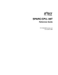
• When the polarity of the INT0 to INT5 pins is changed, the interrupt request bit is sometimes set to “1”.
After changing the polarity, set the interrupt request bit to “0”. Figure 1.11.13 shows the procedure for
______
changing the INT interrupt generate factor.
1-1
Mitsubishi microcomputers
M16C / 62A Group
Precautions for Interrupts
SINGLE-CHIP 16-BIT CMOS MICROCOMPUTER
Clear the interrupt enable flag to “0”
(Disable interrupt)
Set the interrupt priority level to level 0
(Disable INTi interrupt)
Set the polarity select bit
Clear the interrupt request bit to “0”
Set the interrupt priority level to level 1 to 7
(Enable the accepting of INTi interrupt request)
Set the interrupt enable flag to “1”
(Enable interrupt)
Note: Execute the setting above individually. Don't execute two or
more settings at once(by one instruction).
______
Figure 1.11.13. Switching condition of INT interrupt request
(5) Rewrite the interrupt control register
• To rewrite the interrupt control register, do so at a point that does not generate the interrupt request for
that register. If there is possibility of the interrupt request occur, rewrite the interrupt control register after
the interrupt is disabled. The program examples are described as follow:
Example 1:
INT_SWITCH1:
FCLR
I
AND.B #00h, 0055h
NOP
NOP
FSET
I
; Disable interrupts.
; Clear TA0IC int. priority level and int. request bit.
; Four NOP instructions are required when using HOLD function.
; Enable interrupts.
Example 2:
INT_SWITCH2:
FCLR
I
AND.B #00h, 0055h
MOV.W MEM, R0
FSET
I
; Disable interrupts.
; Clear TA0IC int. priority level and int. request bit.
; Dummy read.
; Enable interrupts.
Example 3:
INT_SWITCH3:
PUSHC FLG
FCLR
I
AND.B #00h, 0055h
POPC FLG
; Push Flag register onto stack
; Disable interrupts.
; Clear TA0IC int. priority level and int. request bit.
; Enable interrupts.
The reason why two NOP instructions (four when using the HOLD function) or dummy read are inserted
before FSET I in Examples 1 and 2 is to prevent the interrupt enable flag I from being set before the
interrupt control register is rewritten due to effects of the instruction queue.
• When a instruction to rewrite the interrupt control register is executed but the interrupt is disabled, the
interrupt request bit is not set sometimes even if the interrupt request for that register has been generated. This will depend on the instruction. If this creates problems, use the below instructions to change
the register.
Instructions : AND, OR, BCLR, BSET
1-2
Mitsubishi microcomputers
M16C / 62A Group
SINGLE-CHIP 16-BIT CMOS MICROCOMPUTER
CPU Rewrite Mode (Flash Memory Version)
Precautions on CPU Rewrite Mode
Described below are the precautions to be observed when rewriting the flash memory in CPU rewrite
mode.
(1) Operation speed
During CPU rewrite mode, set the BCLK as shown below using the main clock divide ratio select bit
(bit 6 at address 000616 and bits 6 and 7 at address 000716):
6.25 MHz or less when wait bit (bit 7 at address 000516) = 0 (without internal access wait state)
12.5 MHz or less when wait bit (bit 7 at address 000516) = 1 (with internal access wait state)
(2) Instructions inhibited against use
The instructions listed below cannot be used during CPU rewrite mode because they refer to the
internal data of the flash memory:
UND instruction, INTO instruction, JMPS instruction, JSRS instruction, and BRK instruction
(3) Interrupts inhibited against use
The address match interrupt cannot be used during CPU rewrite mode because they refer to the
internal data of the flash memory. If interrupts have their vector in the variable vector table, they can be
_______
used by transferring the vector into the RAM area. The NMI and watchdog timer interrupts can be
used because the flash memory conterol register 0 and 1 is forcibly initialized and return to normal
mode when each interrupt occurs. But it is needed that the jump addresses for each interrupt are set
in the fixed vector table and there is an interrupt program. Since the rewrite operation is halted when
_______
the NMI and watchdog timer interrupts occur, it is needed that CPU rewriting mode select bit is set to
“1” and the erase/program operation is performed over again.
(4) Internal reserved area expansion bit (Bit 3 at address 000516)
The reserved area of the internal memory can be changed by using the internal reserved area expansion bit (bit 3 at address 000516). However, if the CPU rewrite mode select bit (bit 1 at address 03B716)
is set to 1, the internal reserved area expansion bit (bit 3 at address 000516) also is set to 1 automatically. Similarly, if the CPU rewrite mode select bit (bit 1 at address 03B716) is set to 0, the internal
reserved area expansion bit (bit 3 at address 000516) also is set to 0 automatically.
The precautions above apply to the products which RAM size is over 15 Kbytes or flash memory size
is over 192 Kbytes.
(5) Reset
Reset input is always accepted. After a reset, the addresses 0C000016 through 0CFFFF16 are made
a reserved area and cannot be accessed. Therefore, if your product has this area in the user ROM
area, do not write any address of this area to the reset vector. This area is made accessible by
changing the internal reserved area expansion bit (bit 3 at address 000516) in a program.
(6) Access disable
Write CPU rewrite mode select bit, flash memory power supply-OFF bit and user ROM area select bit
only when executing out of an area other than the internal flash memory.
(7) How to access
For CPU rewrite mode select bit, lock bit disable select bit, and flash memory power supply-OFF bit to
be set to “1”, the user needs to write a “0” and then a “1” to it in succession. When it is not this
procedure, it is not enacted in “1”. This is necessary to ensure that no interrupt or DMA transfer will be
executed during the interval.
Write CPU rewrite mode select bit only when executing out of an area other than the internal flash
_______
memory. Also only when NMI pin is “H” level.
1-3
Mitsubishi microcomputers
M16C / 62A Group
CPU Rewrite Mode (Flash Memory Version)
SINGLE-CHIP 16-BIT CMOS MICROCOMPUTER
(8) Writing in the user ROM area
If power is lost while rewriting blocks that contain the flash rewrite program with the CPU rewrite mode,
those blocks may not be correctly rewritten and it is possible that the flash memory can no longer be
rewritten after that. Therefore, it is recommended to use the standard serial I/O mode or parallel I/O
mode to rewrite these blocks.
(9) Using the lock bit
To use the CPU rewrite mode, use a boot program that can set and cancel the lock command.
1-4
Mitsubishi microcomputers
Protect
M16C / 62A Group
SINGLE-CHIP 16-BIT CMOS MICROCOMPUTER
2.1.3 Precaution for Protect
(1) The write-enable bit of port 9 direction register and SI/Oi control register (i=3,4) goes to “0”
when the next write instruction is executed after write-enabled state is readied. Make
changes in input/output and SI/Oi control register (i=3,4) immediately after the instruction that
sets “1” in the write-enable bit of port P9 direction register and SI/Oi control register
(i=3,4)(avoid causing an interrupt). Also take measures to prevent DMA transfer from being
executed.
2-1
Mitsubishi microcomputers
M16C / 62A Group
Timer A
SINGLE-CHIP 16-BIT CMOS MICROCOMPUTER
2.2.13 Precautions for Timer A (timer mode)
(1) To clear reset, the count start flag is set to “0”. Set a value in the timer Ai register, then set the
flag to “1”.
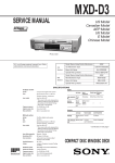
(2) Reading the timer Ai register while a count is in progress allows reading, with arbitrary timing,
the value of the counter. Reading the timer Ai register with the reload timing shown in Figure
2.2.28 gets “FFFF16”. Reading the timer Ai register after setting a value in the timer Ai register with a count halted but before the counter starts counting gets a proper value.
Reload
Counter value (Hex.)
2
1
0
n
n–1
Read value (Hex.)
2
1
0
FFFF
n–1
Time
n = reload register content
Figure 2.2.28. Reading timer Ai register
2-2
Mitsubishi microcomputers
M16C / 62A Group
Timer A
SINGLE-CHIP 16-BIT CMOS MICROCOMPUTER
2.2.14 Precautions for Timer A (event counter mode)
(1) To clear reset, the count start flag is set to “0”. Set a value in the timer Ai register, then set the
flag to “1”.
(2) Reading the timer Ai register while a count is in progress allows reading, with arbitrary timing,
the value of the counter. Reading the timer Ai register with the reload timing shown in Figure
2.2.29 gets “FFFF16” by underflow or “000016” by overflow. Reading the timer Ai register after
setting a value in the timer Ai register with a count halted but before the counter starts counting gets a proper value.
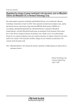
(3) Please note the standards for the differences between the 2 pulses used in the 2-phase pulse
signals input signals to the TAiIN pin and TAiOUT pin (i = 2, 3, 4), as shown in Figure 2.2.30.
(4) When free run type is selected, if count is stopped, set a value in the timer Ai register again.
(1) Down count
(2) Up count
Reload
Counter value
(Hex.)
2
1
0
Read value
(Hex.)
2
1
0
n
A
A
Reload
n–1
FFFF n – 1
Counter value
(Hex.)
FFFD FFFE FFFF
Read value
(Hex.)
FFFD FFFE FFFF 0000 n + 1
Time
n = reload register content
n
n+1
Time
n = reload register content
Figure 2.2.29. Reading timer Ai register
T1
TA2IN
TA3IN
TA4IN
TA2OUT
TA3OUT
TA4OUT
Vcc = 5V, f(XIN) = 16MHz
T1
(Min.)
T2, T3
(Min.)
800ns
200ns
Vcc = 3V, f(XIN) = 10MHz, one-wait
T2
T3
T1
(Min.)
T2, T3
(Min.)
2µs
500ns
Figure 2.2.30. Standard of 2-phase pulses
2-3
Mitsubishi microcomputers
M16C / 62A Group
Timer A
SINGLE-CHIP 16-BIT CMOS MICROCOMPUTER
2.2.15 Precautions for Timer A (one-shot timer mode)
(1) At reset, the count start flag is set to “0”. Set a value in the timer Ai register, then set the flag
to “1”.
(2) Setting the count start flag to “0” while a count is in progress causes as follows:
• The counter stops counting and a content of reload register is reloaded.
• The TAiOUT pin outputs “L” level.
• The interrupt request generated and the timer Ai interrupt request bit goes to “1”.
(3) The output from the one-shot timer synchronizes with the count source generated internally.
Therefore, when an external trigger has been selected, a delay of one cycle of the maximum
count source occurs between the trigger input to the TAiIN pin and the one-shot timer output.
(4) The timer Ai interrupt request bit goes to “1” if the timer's operation mode is set using any of
the following procedures:
• Selecting one-shot timer mode after reset.
• Changing operation mode from timer mode to one-shot timer mode.
• Changing operation mode from event counter mode to one-shot timer mode.
Therefore, to use timer Ai interrupt (interrupt request bit), set timer Ai interrupt request bit to
“0” after the above listed changes have been made.
(5) If a trigger occurs while a count is in progress, after the counter performs one down count
following the reoccurrence of a trigger, the reload register contents are reloaded, and the
count continues. To generate a trigger while a count is in progress, generate the second
trigger after an elapse longer than one cycle of the timer's count source after the previous
trigger occurred.
TAiIN pin input signal
“H”
“L”
Trigger input
Count source
One-shot pulse
output from TAiOUT pin
Start one-shot pulse output
Note: The above applies when an external trigger (falling edge of TAiIN pin input signal) is selected.
Figure 2.2.31. One-shot timer delay
2-4
Mitsubishi microcomputers
Timer A
M16C / 62A Group
SINGLE-CHIP 16-BIT CMOS MICROCOMPUTER
2.2.16 Precautions for Timer A (pulse width modulation mode)
(1) To clear reset, the count start flag is set to “0”. Set a value in the timer Ai register, then set the
flag to “1”.
(2) The timer Ai interrupt request bit becomes “1” if setting operation mode of the timer in compliance with any of the following procedures:
• Selecting PWM mode after reset.
• Changing operation mode from timer mode to PWM mode.
• Changing operation mode from event counter mode to PWM mode.
Therefore, to use timer Ai interrupt (interrupt request bit), set timer Ai interrupt request bit to
“0” after the above listed changes have been made.
(3) Setting the count start flag to “0” while PWM pulses are being output causes the counter to
stop counting. If the TAiOUT pin is outputting an “H” level in this instance, the output level
goes to “L”, and the timer Ai interrupt request bit goes to “1”. If the TAiOUT pin is outputting an
“L” level in this instance, the level does not change, and the timer Ai interrupt request bit does
not becomes “1”.
2-5
Mitsubishi microcomputers
M16C / 62A Group
Timer B
SINGLE-CHIP 16-BIT CMOS MICROCOMPUTER
2.3.6 Precautions for Timer B (timer mode, event counter mode)
(1) To clear reset, the count start flag is set to “0”. Set a value in the timer Bi register, then set the
flag to “1”.
(2) Reading the timer Bi register while a count is in progress allows reading, with arbitrary timing,
the value of the counter. Reading the timer Bi register with the reload timing shown in Figure
2.3.12 gets “FFFF16”. Reading the timer Bi register after setting a value in the timer Bi register with a count halted but before the counter starts counting gets a proper value.
Reload
Counter value (Hex.)
2
1
0
n
n–1
Read value (Hex.)
2
1
0
FFFF
n–1
Time
n = reload register content
Figure 2.3.12. Reading timer Bi register
2-6
Mitsubishi microcomputers
Timer B
M16C / 62A Group
SINGLE-CHIP 16-BIT CMOS MICROCOMPUTER
2.3.7 Precautions for Timer B (pulse period/pulse width measurement mode)
(1) The timer Bi interrupt request bit goes to “1” when an effective edge of a measurement pulse
is input or timer Bi is overflowed. The factor of interrupt request can be determined by use of
the timer Bi overflow flag within the interrupt routine.
(2) If the timer overflow occurs simultaneously with the input of a measurement pulse, and if the
interrupt factor cannot be determined from the timer Bi overflow flag, connect the timers and
count the number of overflows.
(3) When reset, the timer Bi overflow flag goes to “1”. This flag can be set to “0” by writing to the
timer Bi mode register when the count start flag is “1”.
(4) Use the timer Bi interrupt request bit to detect only overflows. Use the timer Bi overflow flag
only to determine the interrupt factor within the interrupt routine.
(5) When the first effective edge is input after a count is started, an indeterminate value is transferred to the reload register. At this time, timer Bi interrupt request is not generated.
(6) The value of the counter is indeterminate at the beginning of a count. Therefore, the timer Bi
overflow flag may go to “1” and timer Bi interrupt request may be generated during the interval between a count start and an effective edge input.
(7) If changing the measurement mode select bits are set after a count is started, the timer Bi
interrupt request bit goes to “1”. Note that the timer Bi interrupt request bit does not change if
the same value as before is written to the measurement mode select bits.
(8) If the input signal to the TBiIN pin is affected by noise, precise measurement may not be
performed in some cases. It is recommended to see that measurements fall within a specific
range by use of software.
(9) For pulse width measurement, pulse widths are successively measured. Use software to
check whether the measurement result is an “H” level width or an “L” level width.
2-7
Mitsubishi microcomputers
M16C / 62A Group
Clock-Synchronous Serial I/O
SINGLE-CHIP 16-BIT CMOS MICROCOMPUTER
2.4.5 Precautions for Serial I/O (in clock-synchronous serial I/O)
Transmission/reception
_______
________
(1) With an external clock selected, and choosing the RTS function, the output level of the RTSi
pin goes to “L” when the data-receivable status becomes ready, which informs the transmis________
sion side that the reception has become ready. The output level of the RTSi pin goes to “H”
________
________
when reception starts. So if the RTSi pin is connected to the CTSi pin on the transmission
side, the circuit can transmission and reception data with consistent timing. With the internal
_______
clock, the RTS function has no effect. Figure 2.4.16 shows an example of wiring.
Transmitter side IC
TxDi
TxDi
RxDi
RxDi
CLKi
CLKi
CTSi
RTSi
Figure 2.4.16. Example of wiring
2-8
Receiver side IC
Mitsubishi microcomputers
Clock-Synchronous Serial I/O
M16C / 62A Group
SINGLE-CHIP 16-BIT CMOS MICROCOMPUTER
Transmission
(1) With an external clock selected, perform the following set-up procedure with the CLKi pin
input level = “H” if the CLK polarity select bit = “0” or with the CLKi pin input level = “L” if the
CLK polarity select bit = “1”:
1. Set the transmit enable bit (to “1”)
2. Write transmission data to the UARTi transmit buffer register
________
_______
3. “L” level input to the CTSi pin (when the CTS function is selected)
Reception (1) In operating the clock-synchronous serial I/O, operating a transmitter generates a shift clock.
Fix settings for transmission even when using the device only for reception. Dummy data is
output to the outside from the TxDi pin (transmission pin) when receiving data.
(2) With the internal clock selected, setting the transmit enable bit to “1” (transmission-enabled
status) and setting dummy data in the UARTi transmission buffer register generates a shift
clock.
With the external clock selected, a shift clock is generated when the transmit enable bit is set
to “1”, dummy data is set in the UARTi transmit buffer register, and the external clock is input
to the CLKi pin.
(3) In receiving data in succession, an overrun error occurs when the next reception data is made
ready in the UARTi receive register with the receive complete flag set to “1” (before the
content of the UARTi receive buffer register is read), and overrun error flag is set to “1”. In this
instance, the next data is written to the UARTi receive buffer register, so handle with this
problem by writing programs on transmission side and reception side so that the previous
data is transmitted again.
If an overrun error occurs, the UARTi receive interrupt request bit does not change.
(4) To receive data in succession, set dummy data in the lower-order byte of the UARTi transmit
buffer register every time reception is made.
(5) With an external clock selected, perform the following set-up procedure with the CLKi pin
input level = “H” if the CLK polarity select bit = “0” or with the CLKi pin input level = “L” if the
CLK polarity select bit = “1”:
1. Set receive enable bit (to “1”)
2. Set transmit enable bit (to “1”)
3. Write dummy data to the UARTi transmit buffer register
_______
(6) Output from the RTS pin goes to “L” level as soon as the receive enable bit is set to “1”. This
is not related to the content of the transmit buffer empty flag or the content of the transmit
enable bit.
_______
Output from the RTS pin goes to “H” level when reception starts, and goes to “L” level when
reception is completed. This is not related to the content of the transmit buffer empty flag or
the content of the receive complete flag.
2-9
Mitsubishi microcomputers
M16C / 62A Group
A-D Converter
SINGLE-CHIP 16-BIT CMOS MICROCOMPUTER
2.7.10 Precautions for A-D Converter
(1) Write to each bit (except bit 6) of A-D control register 0, to each bit of A-D control register 1,
and to bit 0 of A-D control register 2 when A-D conversion is stopped (before a trigger occurs).
In particular, when the Vref connection bit is changed from 0 to 1, start A-D conversion after
an elapse of 1 µs or longer.
(2) To reduce conversion error due to noise, connect a voltage to the AVcc pin and to the Vref pin from
an independent source. It is recommended to connect a capacitor between the AVss pin and the
AVcc pin, between the AVss pin and the Vref pin, and between the AVss pin and the analog input
pin (ANi). Figure 2.7.22 shows the an example of connecting the capacitors to these pins.
Microcomputer
VCC
AVCC
VREF
C1
C2
AVSS
C3
ANi
Note 1: C1≥0.47 µF, C2≥0.47 µF, C3≥100 pF
(for reference)
Note 2: Use thick and shortest possible wiring
to connect capacitors.
Figure 2.7.22. Use of capacitors to reduce noise
(3) Set the direction register of the following ports to input: the port corresponding to a pin to be
used as an analog input pin and external trigger input pin (P97).
(4) In using a key-input interrupt, none of the 4 pins (AN4 through AN7) can be used as an A-D
conversion port (if the A-D input voltage goes to “L” level, a key-input interrupt occurs).
(5) If using the A-D converter with Vcc = 2.7V to 4.0 V:
Use only a divided frequency for fAD (undivided fAD is not allowed).
Select without the Sample & Hold feature.
Select 8-bit mode.
(6) Rewrite to analog input pin select bits after changing A-D operation mode.
(7) When using the one-shot or single sweep mode
Confirm that A-D conversion is complete before reading the A-D register.
(Note: When A-D conversion interrupt request bit is set, it shows that A-D conversion is completed.)
(8) When using the repeat mode or repeat sweep mode 0 or 1
Use the undivided main clock as the internal CPU clock.
(9) Use AD under 10 MHz. When XIN is over 10 MHz, divide it.
2-10
Mitsubishi microcomputers
Power Control
M16C / 62A Group
SINGLE-CHIP 16-BIT CMOS MICROCOMPUTER
2.15.4 Precautions in Power Control
______
(1) The processor does not switch to stop mode when the NMI pin is at “L” level.
____________
(2) When returning from stop mode by hardware reset, RESET pin must be set to “L” level until
main clock oscillation is stabilized.
(3) When switching to either wait mode or stop mode, instructions occupying four bytes either
from the WAIT instruction or from the instruction that sets the all clock stop control bit to “1”
within the instruction queue are prefetched and then the program stops. So put at least four
NOPs in succession either to the WAIT instruction or to the instruction that sets the all clock
stop control bit to “1”.
(4) Before the count source for BCLK can be changed from XIN to XCIN or vice versa, the clock to
which the count source is going to be switched must be oscillating stably. Allow a wait time in
software for the oscillation to stabilize before switching over the clock.
(5) Suggestions to reduce power consumption
(a) Ports
The processor retains the state of each programmable I/O port even when it goes to
wait mode or to stop mode. A current flows in active I/O ports. A pass current flows in
input ports that float. When entering wait mode or stop mode, set non-used ports to
input and stabilize the potential.
(b) A-D converter
A current always flows in the VREF pin. When entering wait mode or stop mode, set
the Vref connection bit to “0” so that no current flows into the VREF pin.
(c) D-A converter
The processor retains the D-A state even when entering wait mode or stop mode.
Disable the output from the D-A converter then work on the programmable I/O ports.
Set D-A register to “0016”.
(d) Stopping peripheral functions
In wait mode, stop non-used peripheral functions using the WAIT peripheral function
clock stop bit. However, peripheral function clock fC32 does not stop so that the peripherals using fC32 do not contribute to the power saving. When the MCU running in
low-speed or low power dissipation mode, do not enter WAIT mode with this bit set to
“1”.
(e) Switching the oscillation-driving capacity
Set the driving capacity to “LOW” when oscillation is stable.
(f ) External clock
When using an external clock input for the CPU clock, set the main clock stop bit to
“1”. Setting the main clock stop bit to “1” causes the XOUT pin not to operate and the
power consumption goes down (when using an external clock input, the clock signal
is input regardless of the content of the main clock stop bit).
2-11
Mitsubishi microcomputers
External Buses
M16C / 62A Group
SINGLE-CHIP 16-BIT CMOS MICROCOMPUTER
4.6 Precautions for External Bus
(1) The external ROM version can operate only in the microprocessor mode, so be sure to perform the following:
• Connect the CNVSS pin to Vcc.
2-12
Related to M16C/80, M16C/60, M16C/20 series devices.
A
GRADE
MSC TECHNICAL NEWS
No.M16C-09-9705
Note on using the A-D converter
of the M16C/60 series MCU
1. Related devices
M16C/60 series
2. Symptoms
After A-D conversion is complete, if the CPU reads the A-D register at the same time as the A-D conversion
result is being saved to A-D register, wrong A-D conversion value is saved into the A-D register. This happens
when the internal CPU clock is selected from divided main clock or sub-clock.
(When connected an A-D input port and GND)
Start A-D conversion
A-D conversion complete
Start A-D conversion
10-bit resolution:
with sample & hold is activated, 33 φAD cycles used
φAD
Final conversion result
A-D conversion buffer
001H
000H
200H
100H
Normal latch signal
Transfer signal to A-D register
Read signal to A-D register
A-D register
Wrong latch signal when
a CPU read is present
The former conversion result
000H
200H
Start the next A-D conversion
Normally, A-D conversion value is saved at the rising edge (dashed rising edge) of the latch signal.
However, when the CPU is doing a read to A-D register at this time, the A-D register latch signal is
delayed, and wrong value is stored at A-D conversion register.
3. Precaution
(1) When using the one-shot or single sweep mode
Confirm that A-D conversion is complete before reading the A-D register.
(Note: When A-D conversion interrupt request bit is set, it shows that A-D conversion is completed.)
(2) When using the repeat mode or repeat sweep mode 0 or 1
Use the undivided main clock as the internal CPU clock.
(1/1)
Related to M16C/80, M16C/60, M16C/20 series devices.
GRADE
MESC TECHNICAL NEWS
A
No.M16C-11-9710
Note on dedicated input pin of the M16C/60 series MCU
1. Related devices
M16C/60 series
2. Note on dedicated input pin
When different power supplied to the system as shown in figure 1, and input voltage of unused
dedicated input pin is larger than voltage of VCC pin, do not connect dedicated input pin and
power supply directly. Connect to VCC via resistor (approximately 1kohm) as shown in figure
2. This note is also applicable when VINPUT exceeds VCC during power-up.
Different power supply
Different power supply
VCC
Dedicated
input pin
(e.g. NMI)
VCC
Dedicated
input pin
(e.g. NMI)
M16C/60 series
microcomputer
M16C/60 series
microcomputer
Figure 1. Circuit diagram
Figure 2. Improved circuit diagram
* The resistor is not necessary when VCC pin voltage is same or larger than dedicated input pin voltage.
3. Cause
When dedicated input pin voltage is larger than VCC pin voltage, latch up occurs.
(1/1)
Related to M16C/60, M16C/20 series devices.
GRADE
A
MESC TECHNICAL NEWS No.M16C-12-9711
Note on the interrupt control register
of the M16C/60 series MCU
1. Related devices
M16C/60 series
2. Note
Do not rewrite to interrupt control register when the interrupt enable flag is enable
state ( I flag = "1" ). A rewrite instruction includes read modify write instructions
such as BSET.
3. Cause
If the interrupt request bit is cleared ("0") or the interrupt priority level is changed
after the interrupt request bit is set ("1"), the interrupt information may not be
read correctly when reading address 0000016 in interrupt sequence. As a result,
another interrupt( e.g. BRK instruction interrupt ) may occur.
4. Solution
When you want to rewrite to interrupt control register, clear interrupt enable flag
( I flag = "0" ) before rewriting interrupt control register.
(1/1)
Related to M16C/60, M16C/20 series devices.
GRADE
A
MESC TECHNICAL NEWS No.M16C-13-9802
Supplemental Description of DMAC for the M16C/60,
M16C/61 and M16C/62 Group MCUs
1. Related devices
M16C/60, M16C/61 and M16C/62 groups
2. DMA enable bit
The DMA enable bit is bit 3 of both DMA0 and DMA1 control registers.
When the DMA enable bit is set to "1" the DMAC is in an active state and the following occurs:
a. The value of whichever of the source or destination pointer that is set up as the forward
pointer is reloaded into the forward address pointer.
b. The value in the transfer counter reload register is reloaded into the transfer counter.
Therefore, the DMAC will start from the initial conditions once again if the DMA enable bit is set
to "1" while in the active state.
3. DMA request bit
The DMA request bit is bit 2 of both DMA0 and DMA1 control registers.
Regardless of the DMAC status (enable bit set or clear), the request bit is set to "1" when a
request signal for a DMA transfer occurs, based on the DMA request factor. The bit is cleared
to "0" when data transfer begins. Further, the user can clear ("0") the DMA request bit but not
set it.
It is possible that the DMA request bit may become "1" due to the DMA request cause select
bits being changed. Therefore the DMA request bit should be cleared ("0") after changing the
DMA request cause select bits.
If DMAC is in the active state (enable bit set) when the request bit becomes "1", the data
transfer begins immediately. That in turn immediately causes the DMA request bit to be cleared
("0"). Therefore, to best judge the state of the DMAC, the DMA enable bit should be read
instead of the request bit.
(1/2)
No.M16C-13-9802
4. Initialization of DMA-related registers
START
No
DMA enable bit = "0"?
Yes
Set DMA control register
Select DMA request cause
Set source pointer
Set destination pointer
Set DMA transfer counter
DMA request bit
DMA enable bit
END
(2/2)
"0"
"1"
Related to M16C/60, M16C/20 series devices.
GRADE
A
MESC TECHNICAL NEWS No.M16C-14-9805
Precautions Regarding Writing to M16C/60, M16C/61, M16C/62 and
M16C/63 Group MCUs Interrupt Control Registers
1. Related devices
M16C/60, M16C/61, M16C/62 and M16C/63 groups
With the M16C/60 series MCU, setting the interrupt priority level and clearing the interrupt
request bit in the interrupt control registers should be done with interrupt disabled.
Executing these operations while interrupt is enabled may result in unintended CPU operations.
2. Symptom
Changing the Interrupt priority LeVeL select bit (ILVL) and clearing the Interrupt Request bit
(IR) in the Interrupt Control Registers (ICRs) while the Interrupt enable FLAG (I-FLAG) is "1"
may result in unintended operations, such as BRK and other interrupts being generated.
3. Considerations for writing new program
It is recommended that the interrupts must be disabled by clearing the I-FLAG, before setting
ILVL or clearing the IR bit in the ICRs.
In order to avoid the influence of the CPU pipeline, a certain number of instructions (eg. NOP)
should be inserted between writing to the ICRs and setting the I-FLAG.
The number of instructions (NOPs) required is shown in TABLE.
(1/3)
No.M16C-14-9805
4. Conditions to be checked for program already written
Please confirm that at least one condition is met for both actions listed below. If any one of the
conditions is met, the symptom will not occur.
(1) When changing ILVL
- I-FLAG is "0". (Interrupt disabled) (*Note)
- The processor interrupt priority level (IPL) in the flag register is "7".
- The ILVL changes from a lower level than IPL to a higher level.
- The ILVL before and after the change is lower than IPL.
- The ILVL before and after the change is higher than IPL.
- It is obvious that the corresponding interrupt will not occur while changing the ILVL.
(2) When clearing the IR
- I-FLAG is "0". (Interrupt disabled) (*Note)
- The IPL in the flag register is "7".
- The ILVL during the operation is "0".
- The ILVL is lower than IPL.
- It is obvious that the corresponding interrupt will not occur while clearing the IR.
Note: In order to avoid the influence of the CPU pipeline, a certain number of instructions (eg.
NOP) should be inserted between writing to ICRs and setting the I-FLAG.
The number of instructions required is showed in the TABLE.
When not using HOLD function
When using HOLD function
Example 1
Two NOP instructions required
Four NOP instructions required
Example 2
No NOP instruction required (because there is dummy read)
Example 3
No NOP instruction required
(2/3)
No.M16C-14-9805
5. Program examples
The program examples are described as follow:
(1) For assembler
Example 1:
INT_SWITCH1:
FCLR
I
; Disable interrupts.
AND.B #00h, 0055h ; Clear TA0IC int. priority level and int. request bit.
NOP
; Four NOP instructions are required when using HOLD function.
NOP
FSET
I
; Enable interrupts.
Example 2:
INT_SWITCH2:
FCLR
I
; Disable interrupts.
AND.B #00h, 0055h ; Clear TA0IC int. priority level and int. request bit.
MOV.W
FSET
MEM, R0
I
; Dummy read.
; Enable interrupts.
Example 3:
INT_SWITCH3:
PUSHC FLG
;
FCLR
I
;
AND.B #00h, 0055h ;
POPC
FLG
;
Push Flag register onto stack
Disable interrupts.
Clear TA0IC int. priority level and int. request bit.
Enable interrupts.
The reason why two NOP instructions (four when using the HOLD function) or dummy read are inserted
before FSET I in Examples 1 and 2 is to prevent the interrupt enable flag I from being set before the
interrupt control register is rewritten due to effects of the instruction queue.
(2) For C language
#pragma ASM
INT_SWITCH:
FCLR
I
#pragma ENDASM
TA0IC & =00 ;
#pragma ASM
NOP
NOP
FSET
I
#pragma ENDASM
/* Clear TA0IC int. priority level and int. request bit. */
; Four NOP instructions are required when using HOLD function.
(3/3)
Related to M16C/60, M16C/20 series devices.
GRADE
A
MESC TECHNICAL NEWS No.M16C-17-9902
M16C/60 Group, M16C/61 Group, M16C/62 Group
Precautions For Power Control State Transitions
1. Related devices
M16C/60 group, M16C/61 group, M16C/62 group
2. Precautions
Power control state transition is shown on the next page.
Please change modes according to a directions of arrows.
When count source of BCLK is changed from clock A to clock B (XIN to XCIN or XCIN to XIN),
clock B needs to be stable before changing.
Please wait to change modes until after oscillation has stabilized.
The delay time is depends on the oscillator. Please refer to the oscillator manufacture's
specifications.
(1/2)
No.M16C-17-9902
Transition of stop mode, wait mode
Reset
WAIT
instruction
All oscillators stopped
CM10=“1”
Medium-speed mode
(Divided-by-8 mode)
Stop mode
Interrupt
Wait mode
Interrupt
Interrupt
All oscillators stopped
Stop mode
CPU operation stopped
CPU operation stopped
WAIT
instruction
CM10=“1”
High-speed/mediumspeed mode
Wait mode
Interrupt
All oscillators stopped
CM10=“1”
Low-speed/low power
dissipation mode
Stop mode
Interrupt
CPU operation stopped
WAIT
instruction
Wait mode
Interrupt
Normal mode
(Please see the following as transition of normal mode.)
Transition of normal mode
Main clock is oscillating
Sub clock is stopped
Medium-speed mode
(divided-by-8 mode)
CM06=“1”
BCLK :f(XIN)/8
CM07=“0” CM06=“1”
High-speed mode
Note 1
Note 1, 3
Medium-speed mode
(divided-by-2 mode)
BCLK :f(XIN)
CM07=“0” CM06=“0”
CM17=“0” CM16=“0”
Medium-speed mode
(divided-by-4 mode)
CM04=“1”
CM04=“0”
Main clock is oscillating
Sub clock is oscillating
CM07=“0”
CM06=“1”
CM04=“0”
Main clock is oscillating
Sub clock is oscillating
Low-speed mode
CM07=“0”
Medium-speed mode
(divided-by-8 mode)
BCLK :f(XIN)/2
CM07=“0” CM06=“0”
CM17=“0” CM16=“1”
Note 1, 3
BCLK :f(XIN)/8
CM07=“0”
CM06=“1”
Medium-speed mode
(divided-by-16 mode)
BCLK :f(XCIN)
CM07=“1”
CM07=“1”
Note 2
BCLK :f(XIN)/16
BCLK :f(XIN)/4
CM07=“0” CM06=“0”
CM17=“1” CM16=“0”
CM07=“0” CM06=“0”
CM17=“1” CM16=“1”
CM05=“0”
CM04=“1”
CM04=“0”
CM05=“1”
Main clock is oscillating
Sub clock is stopped
High-speed mode
CM06=“0”
Note 1
Note 3
CM07=“1”
CM05=“1”
Medium-speed mode
(divided-by-2 mode)
BCLK :f(XIN)
CM07=“0” CM06=“0”
CM17=“0” CM16=“0”
BCLK :f(XIN)/2
CM07=“0” CM06=“0”
CM17=“0” CM16=“1”
Medium-speed mode
(divided-by-4 mode)
Medium-speed mode
(divided-by-16 mode)
BCLK :f(XIN)/4
CM07=“0” CM06=“0”
CM17=“1” CM16=“0”
CM07=“0” CM06=“0”
CM17=“1” CM16=“1”
BCLK :f(XIN)/16
Note 1: Switch clocks after oscillation of main clock is fully stable.
Note 2: Switch clocks after oscillation of sub clock is fully stable.
Note 3: Change CM17 and CM16 before CM06.
Note 4: Please change according to a direction of an arrow.
(2/2)
Note 2
BCLK :f(XCIN)
CM07=“0”
CM06=“0”
CM04=“1”
Note 1
Note 3
CM07=“1”
Main clock is stopped
Sub clock is oscillating
Low power
dissipation mode
Related to M16C/60 series devices.
GRADE
A
MESC TECHNICAL NEWS No.M16C-19-9903
MESC TECHNICAL NEWS
'No.M16C-16-9902' replace
MESC TECHNICAL NEWS 'No.M16C-16-9902' has an error, so we will correct.
Please replace old Technical News 'No.M16C-16-9902' to corrected Technical News 'M16C/60,
M16C/61, M16C/62 Group Precautions for Setting Pull-up Resistors'.
[Attached]
Corrected Technical News 'No.M16C-19-9903'
'M16C/60, M16C/61, M16C/62 Group Precautions for Setting Pull-up Resistors' ..... 1 page
(1/2)
GRADE
A
MESC TECHNICAL NEWS No.M16C-19-9903
M16C/60, M16C/61, M16C/62 Group
Precautions for Setting Pull-up Resistors
1. Related devices
M16C/60 group, M16C/61 group, M16C/62 group
2. Precautions
Ports P0 to P10 can be set to apply a pull-up resistor by using the pull-up control registers.
(1) M16C/60 Group, M16C/61 Group
In Memory expansion mode or Microprocessor mode, the settings of pull-up control registers for ports P0 to P5 are invalid.
In Memory expansion mode or Microprocessor mode, ports P0, P1, P31 to P37 and P4 can
be used as input ports, but internal pull-up resistors can not be connected.
(2) M16C/62 Group
In Memory expansion mode or Microprocessor mode, the settings of pull-up control registers for P0 to P3, P40 to P43 and P5 are invalid.
In Memory expansion mode or Microprocessor mode, ports P0, P1, P31 to P37 and P40 to
P43 can be used as input ports, but internal pull-up resistors can not be connected.
(In Memory expansion mode or Microprocessor mode, P44 to P47 can be used as general
input ports, and pull-up control register can be used to connect the internal pull-up resistors.)
(2/2)
Related to M16C/60, M16C/20 series devices.
GRADE
A
MESC TECHNICAL NEWS No.M16C-25-9905
M16C/60 , M16C/20 Series
Precautions for Wait and Stop modes
1. Related devices
M16C/60 Series , M16C/20 Series
2. Precautions
The M16C has both WAIT and STOP modes. These modes can be used to reduce power
consumption when the CPU is not required to perform any work. To return to normal operating
mode after issuing a WAIT instruction or setting the all clock stop control bit, perform a hardware
reset or use an interrupt. The interrupts for canceling the WAIT and STOP modes must be
enabled before entering either mode. The priority level of the interrupts not used for these
modes should be set to 0 before switching into the WAIT or STOP modes. Also, if only hardware
______
reset or NMI interrupts are used for canceling the WAIT or STOP modes, all interrupt priority
level should be set to 0 before switching into the WAIT or STOP mode.
3. Examples
3.1 Use the following algorithm to enter the WAIT or STOP modes when an interrupt is
used to cancel either mode.
______
_______
• Hardware reset, NMI interrupt, and INT0 interrupt is used to cancel either mode
Set the interrupt enable flag (I flag) to “0”
Change the interrupt priority level to 1 or higher
; Disable interrupt
; Enable INT0 interrupt
(In case of processor interrupt priority level=0)
Change all other interrupt priority levels to 0
Insert 4 NOP instructions
Set the interrupt enable flag (I flag) to “1”
WAIT instruction or all clock stop control bit set
Insert 4 NOP instructions
; Disable all other interrupts
; Prevention of irregular interrupts issue.
See TECHNICAL NEWS No.M16C-14-9805
; Enable interrupt
; Set the bit 0 of protect register to “1” before set the all clock stop control bit to “1” .
; NOP instructions are required because M16C instruction queue reads forward 4
bytes from wait or stop instruction when program is stopped.
(1/2)
No.M16C-25-9905
_______
3.2 When using only hardware reset or NMI interrupt to cancel the STOP or WAIT
modes, use the following algorithm to enter the STOP or WAIT modes.
Set the interrupt enable flag (I flag) to “0”
Change all interrupt priority levels to 0
WAIT instruction or all clock stop control bit set
Insert 4 NOP instructions
; Disable interrupt
; Disable maskable interrupt
; Set the bit 0 of protect register to “1” before set the all clock stop control bit to “1” .
; NOP instructions are required because M16C instruction queue reads forward 4
bytes from wait or stop instruction when program is stopped.
(2/2)
Related to M16C/60, M16C/20 series devices.
GRADE
A
MESC TECHNICAL NEWS No.M16C-26-9905
M16C/61 , M16C/62 Group
Precautions for UART2
1. Related devices
M16C/61 Group, M16C/62 Group
2. Precautions
When using UART2 in clock asynchronous serial I/O (UART) mode choose internal clock. If
UART2 in clock asynchronous mode is used with external clock, then one of the following may
occur;
2.1 The interrupt may not be issued at the end of data transmission when the hardware transfers
the data from the transmit buffer register to the transmit register.
2.2 Data may be corrupted when the hardware transfers the data from the transmit buffer
register to the transmit register.
This precaution only applies to the UART2 asynchronous serial I/O mode and does not apply
to UART0 or UART1. It does not apply to any UART when used in the synchronous clocked
serial I/O mode.
Example of transmit with UART mode, Transfer data 8 bits long.
Tc
Transfer clock
Transmit enable
bit(TE)
“1”
Transmit buffer
empty flag(TI)
“1”
Data may be corrupted
when external clock is
selected.
Data is set in UART2 transmit buffer register
“0”
Note
“0”
Transferred from UART2 transmit buffer register to UARTi transmit register
Start
bit
TxD2
Parity
bit
ST D0 D1 D2 D3 D4 D5 D6 D7
P
Stop
bit
SP
ST D0 D1 D2 D3 D4 D5 D6 D7
P
SP
The interrupt request bit
may not be "1" when
external clock is selected.
“1”
Transmit register
empty flag (TXEPT) “0”
Transmit interrupt
request bit (IR)
“1”
“0”
Cleared to “0” when interrupt request is accepted, or cleared by software
Shown in ( ) are bit symbols.
The above timing applies to the following settings :
• Parity is enabled.
• One stop bit.
• Transmit interrupt cause select bit = “0”.
Tc = 16 (n + 1) / fi
fi : frequency of BRG2 count source (f1, f8, f32)
n : value set to BRG2
Note: The transmit is started with overflow timing of BRG after having written in a value at the transmit buffer in the above timing.
(1/1)
Related to M16C/60 series devices.
GRADE
A
MESC TECHNICAL NEWS No.M16C-32-9908
M16C/60 Series
Precautions for Address Match Interrupt
1. Related devices
M16C/60 Series
2. Precautions
When using the address match interrupt, please observe the following usage conditions.
(1) Address match interrupt for internal address.
(2) Address match interrupt for external address and 16-bit bus.
When external address and 8-bit bus, you can not use the address match interrupt for external
address.
(1/1)
Related to M16C/80, M16C/60 series devices.
Related to M16C/20 series devices (except for M30201 group devices).
GRADE
A
MESC TECHNICAL NEWS No.M16C-39-9911
M16C Family
Cautions for “Event counter mode” with Timer A
1. Affected devices
• M16C/80 Group, M16C/60 Group, M16C/61 Group, M16C/62 Group (Included 3V version)
• M16C/62A Group (Included 3V version), M16C/6N Group, M16C/6K Group, M16C/6V Group
• M16C/6H Group, M16C/21 Group, M16C/24 Group
2. Cautions
In the case of using “Event counter mode” as “Free-Run type” for timer A, the timer register contents
may be unknown when counting begins. If the timer register is set before counting has started,
then the starting value will be unknown.
This issue will occur only for the “Event counter mode” operating as “Free-Run type”. The value of
the timer register will not be unknown during counting.
3. Countermeasure
(1) In the case where the up/down count will not be changed.
Enable the “Reload” function and write to the timer register before counting begins. Rewrite the
value to the timer register immediately after counting has started.
If counting up, rewrite “000016” to the timer register.
If counting down, rewrite “FFFF16” to the timer register.
This will cause the same operation as “Free-Run type” mode.
(2) In the case where the up/down count has changed.
First set to “Reload type” operation. Once the first counting pulse has occurred, the timer may be
changed to “Free-Run type”.
( 1 / 1)
Related to M16C/80, M16C/60 series devices.
GRADE
A
MESC TECHNICAL NEWS No.M16C-49-0004
M16C/80 Series, M16C/60 Series
Cautions for Using Memory Expansion Mode or Microprocessor Mode
1. Affected devices
• M16C/80 Series
• M16C/60 Series
2. Cautions
When the MCU enters wait mode while operating in memory expansion mode or microprocessor
mode,
a pin functioning as part of the address or data bus retains it's state on the bus
before wait mode is entered. Shift to single-chip mode and output an arbitrary value in order to
reduce current consumption. By shifting to single-chip mode, a pin which was functioning as part
Set the port
registers and direction registers after shifting to single-chip mode (this implies that
_____ ______ _____
any control pins (CS,WR,RD,etc.. ) being used for access of an external device be
changed as well).
of the bus becomes a general-purpose port and can output an arbitrary value.
If the port registers and direction registers are set while in memory expansion mode or
microprocessor mode, the operation will be ignored.
This is similar when entering stop mode.
Setting procedure is following.
Operate in memory expansion mode or microprocessor mode
Shift to single-chip mode
Set the port register
Note
Set the direction register
Enter the wait mode or stop mode
Note: This program does not work in external area. Transfer a program to
internal RAM and work on internal RAM.
( 1 / 1)
Related to M16C/62 group devices.
GRADE
A
MESC TECHNICAL NEWS No.M16C-54-0004
Difference between M16C/62 and M16C/62A
(include low voltage version)
1. Affected devices
• M16C/62 group
{M16C/62, M16C/62L (low voltage version), M16C/62A, M16C/62M (low voltage version)}
Table 1 shows the product list of M16C/62 and M16C/62A.
Table 2 shows the product list of M16C/62L (low voltage version) and M16C/62M (low voltage
version).
Table 1. Product list of M16C/62 and M16C/62A
M16C/62 group
Memory type
Mask ROM
version
External ROM
version
Flash memory
version
Package
M16C/62
M16C/62A
M30622M4-XXXFP/GP
M30622M4A-XXXFP/GP
FP:100P6S-A
GP:100P6Q-A
M30623M4-XXXGP
M30623M4A-XXXGP
80P6S-A
M30622M8-XXXFP/GP
M30622M8A-XXXFP/GP
FP:100P6S-A
GP:100P6Q-A
M30623M8-XXXGP
M30623M8A-XXXGP
80P6S-A
M30620M8-XXXFP/GP
M30620M8A-XXXFP/GP
FP:100P6S-A
GP:100P6Q-A
M30621M8-XXXGP
M30621M8A-XXXGP
80P6S-A
M30622MA-XXXFP/GP
M30622MAA-XXXFP/GP
FP:100P6S-A
GP:100P6Q-A
M30623MA-XXXGP
M30623MAA-XXXGP
80P6S-A
M30620MA-XXXFP/GP
M30620MAA-XXXFP/GP
FP:100P6S-A
GP:100P6Q-A
M30621MA-XXXGP
M30621MAA-XXXGP
80P6S-A
FP:100P6S-A
GP:100P6Q-A
M30623MC-XXXGP
80P6S-A
M30620MC-XXXFP/GP M30620MCA-XXXFP/GP
FP:100P6S-A
GP:100P6Q-A
M30621MC-XXXGP
80P6S-A
M30621MCA-XXXGP
M30624MG-XXXFP/GP M30624MGA-XXXFP/GP
FP:100P6S-A
GP:100P6Q-A
M30625MG-XXXGP
M30625MGA-XXXGP
80P6S-A
M30620SFP/GP
M30620SAFP/GP
M30622SFP/GP
M30622SAFP/GP
M30624FGFP/GP
M30624FGAFP/GP
FP:100P6S-A
GP:100P6Q-A
FP:100P6S-A
GP:100P6Q-A
FP:100P6S-A
GP:100P6Q-A
M30625FGGP
M30625FGAGP
80P6S-A
M30620FGAFP/GP
FP:100P6S-A
GP:100P6Q-A
M30621FGAGP
80P6S-A
None
( 1 / 3)
32K byte / 3K byte
64K byte /4K byte
64K byte /10K byte
96K byte /5K byte
M30622MC-XXXFP/GP M30622MCA-XXXFP/GP
M30623MCA-XXXGP
ROM/RAM size
96K byte /10K byte
128K byte /5K byte
128K byte /10K byte
256K byte /20K byte
- /10K byte
- /3K byte
256K byte /20K byte
128K byte /10K byte
No.M16C-54-0004
Table 2. Product list of M16C/62L (low voltage version) and M16C/62M (low voltage version)
M16C/62 group
Memory type
M16C/62L
Package
M16C/62M
FP:100P6S-A
M30620MCM-XXXFP/GP GP:100P6Q-A
Mask ROM
version
M30621MCM-XXXGP
None
128K byte /10K byte
80P6S-A
FP:100P6S-A
M30624MGM-XXXFP/GP GP:100P6Q-A
Flash memory
version
ROM/RAM size
M30625MGM-XXXGP
80P6S-A
M30624FGLFP/GP
M30624FGMFP/GP
FP:100P6S-A
GP:100P6Q-A
M30625FGLGP
M30625FGMGP
80P6S-A
M30620FGMFP/GP
FP:100P6S-A
GP:100P6Q-A
M30621FGMGP
80P6S-A
None
256K byte /20K byte
256K byte /20K byte
128K byte /10K byte
2. Contents
Table 3 shows the differences between M16C/62 and M16C/62A.
Table 4 shows the differences between M16C/62L (low voltage version) and M16C/62M (low voltage
version).
Note: In M16C/62A and M16C/62M (low voltage version), built in non-volitile memory is of type Flash
only. One-time PROM and EPROM versions are not availible.
Table 3. Differences between M16C/62 and M16C/62A
M16C/62 group
Item
Remarks
Mask ROM, Flash memory versions common
M16C/62
SDA output
delay function
in I2C mode
(UART2)
Memory space
Separate CTS/RTS
pins function of
serial I/O
Standard serial I/O
mode of flash
memory version
(flash memory
rewrite)
Analog delay
1M byte
Expansion mode 1(1.2Mbyte)
Expansion mode 2(4Mbyte)
Can be selected
Flash memory version
Can be selected analog
delay or digital delay
1M byte
None
Synchronous mode
UART mode
Being done to improve the
left description
Precautions for boot mode
(technical news NO. M16C27-9906, M16C-29-9906)
Precautions for hysteresis
(technical news NO. M16C33-9908)
Reduction of
power supply
electric current
(flash memory
version)
Flash memory
program time
(256K byte)
Standard value at
f(XIN)=16MHz; 35mA
Standard value at
f(XIN)=16MHz; 32.5mA
Standard value at
f(XCIN)=32kHz; 8mA
Standard value at
f(XCIN)=32kHz; 2.2mA
Standard value; Approximately
8 second
For details, refer to
M16C/62A data
sheet.
Single-chip mode is
supported in 80-pin version.
Memory expansion and
microprocessor modes are
not supported in 80-pin
version.
Synchronous mode
Precautions for external bus
timing (technical news NO.
M16C-24-9905)
Restrictions
improvement
(flash memory
version)
M16C/62A
Standard value; Approximately
6 second
(2/3)
No.M16C-54-0004
Table 4. Differences between M16C/62L (low voltage version) and M16C/62M (low voltage version)
M16C/62 group
Mask ROM, Flash memory versions common
Item
Operation
voltage/
frequency
characteristics
M16C/62L
M16C/62M
Vcc=2.7V to 3.6V
( f(XIN)=10MHz, No wait)
Vcc=2.7V to 3.6V
( f(XIN)=10MHz, No wait)
Vcc=2.4V to 3.6V
( f(XIN)=7MHz, No wait)
Vcc=2.4V to 3.6V
( f(XIN)=7MHz, No wait)
Vcc=2.2V to 3.6V
( f(XIN)=7MHz, 1 wait)
SDA output
delay function
in I2C mode
(UART2)
Memory space
Separate CTS/RTS
pins function
of serial I/O
Program/erase
voltage
(flash memory
version)
Analog delay
1M byte
Expansion mode 1(1.2Mbyte)
Expansion mode 2(4Mbyte)
Can be selected analog
delay or digital delay
Can be selected
None
Operation voltage
; Vcc=2.4V to 3.6V
Operation voltage
; Vcc=2.4V to 3.6V
Program/erase voltage
; Vcc=2.7V to 3.6V
Program/erase voltage
; Vcc=2.7V to 3.6V
Program/erase voltage
; Vcc=2.7V to 3.4V
Standard serial I/O
mode of flash
memory version
(flash memory
rewrite)
Synchronous mode
Synchronous mode
UART mode
Precautions for external bus
timing (technical news NO.
M16C-24-9905)
Restrictions
improvement
(flash memory
version)
Being done to improve the
left description
Precautions for boot mode
(technical news NO. M16C27-9906, M16C-29-9906)
Precautions for hysteresis
(technical news NO. M16C33-9908)
Reduction of
power supply
electric current
(flash memory
version)
Standard value at
f(XCIN)=32kHz; 700µA
Flash memory
program time
(256K byte)
Standard value; Approximately
8 second
Standard value at
f(XCIN)=32kHz; 45µA
Standard value; Approximately
6 second
(3/3)
For details refer to
M16C/62A data
sheet.
Single-chip mode is supported in
80-pin version.
Memory expansion and
microprocessor modes are not
supported in 80-pin version.
1M byte
Operation voltage
; Vcc=2.2V to 2.4V
Flash memory version
Remarks
Related to M16C/80, M16C/60, M16C/20 series devices.
GRADE
A
MESC TECHNICAL NEWS No.M16C-55-0006
M16C Family
Cautions Using Data Registers that Include Write Only Bits
1. Affected devices
• M16C Family
2. Cautions
The registers shown in the table on the following page contain bits that will result in unknown data
when read.
If performing a read-modify-write sequence of instructions to a register with write only bits, please
reset the write only bits to their previous values before writing back to the register.
If your software accesses these registers frequently, please use a temporary RAM area to change
the value, and then transfer it to the register.
Figure 1 shows an example of a register structure. If you execute a ‘Read Modify Write’ instruction
like BSET, BCLR, AND or OR, the values of bits 5-7 may change. (Please see Figure 2)
‘Table 10’ show instruction table for Read Modify Write.
Up/down flag
b7
b6
b5
b4
b3
b2
b1
Symbol
UDF
b0
Address
038416
Bit symbol
Bit name
TA0UD
Timer A0 up/down flag
TA1UD
Timer A1 up/down flag
TA2UD
Timer A2 up/down flag
TA3UD
Timer A3 up/down flag
TA4UD
Timer A4 up/down flag
TA2P
TA3P
TA4P
When reset
0016
AA
AA
AA
A
RW
Function
0 : Down count
1 : Up count
This specification becomes valid
when the up/down flag content is
selected for up/down switching
cause
Timer A2 two-phase pulse 0 : two-phase pulse signal
processing disabled
signal processing select bit
1 : two-phase pulse signal
processing enabled
Timer A3 two-phase pulse
signal processing select bit
When not using the two-phase
Timer A4 two-phase pulse pulse signal processing function,
signal processing select bit set the select bit to “0”
Can not read these bits
Figure 1. Example of a register structure
In the case of initial data is “0”, set bit 0 to “1” with the use of
‘BSET’ instruction.
b7
Initial
data
b0
b7
0 0 0 0 0 0 0 0
Read
b7
Write
b0
X X X 0 0 0 0 0
Unknown
Data
b0
X X X 0 0 0 0 1
Modify
b7
The condition
after
executed
BSET
instruction
Figure 2. Example of a register change
( 1 / 5)
b0
X X X 0 0 0 0 1
Different from initial data
No.M16C-55-0006
Table 1. Affected register (M16C/80 group)
Register name
Symbol
Address
UART4 bit rate generator
U4BRG
02F916
UART4 transmit buffer register
U4TB
02FB16 , 02FA16
Dead time timer
DTT
030C16
Timer B2 interrupt occurrences frequency set counter
ICTB2
030D16
UART3 bit rate generator
U3BRG
032916
032B16 , 032A16
UART3 transmit buffer register
U3TB
UART2 bit rate generator
U2BRG
033916
UART2 transmit buffer register
U2TB
033B16 , 033A16
Up/down flag
UDF
034416
Timer A0 register (Note)
TA0
034716 , 034616
Timer A1 register (Note)
TA1
034916 , 034816
Timer A2 register (Note)
TA2
034B16 , 034A16
Timer A3 register (Note)
TA3
034D16 , 034C16
034F16 , 034E16
Timer A4 register (Note)
TA4
UART0 bit rate generator
U0BRG
036116
UART0 transmit buffer register
U0TB
036316 , 036216
UART1 bit rate generator
U1BRG
036916
UART1 transmit buffer register
U1TB
036B16 , 036A16
Note: It is affected only in one-shot timer mode and pulse width modulation mode.
Table 2. Affected register (M16C/61 group)
Register name
UART2 bit rate generator
Symbol
Address
U2BRG
037916
037B16 , 037A16
UART2 transmit buffer register
U2TB
Up/down flag
UDF
038416
Timer A0 register (Note)
TA0
038716 , 038616
Timer A1 register (Note)
TA1
038916 , 038816
Timer A2 register (Note)
TA2
038B16 , 038A16
Timer A3 register (Note)
TA3
038D16 , 038C16
038F16 , 038E16
Timer A4 register (Note)
TA4
UART0 bit rate generator
U0BRG
03A116
UART0 transmit buffer register
U0TB
03A316 , 03A216
UART1 bit rate generator
U1BRG
03A916
UART1 transmit buffer register
U1TB
03AB16 , 03AA16
Note: It is affected only in one-shot timer mode and pulse width modulation mode.
Table 3. Affected register (M16C/62 group)
Register name
Dead time timer
Symbol
DTT
Address
034C16
Timer B2 interrupt occurrences frequency set counter
ICTB2
034D16
SI/O3 bit rate generator
S3BRG
036316
036716
SI/O4 bit rate generator
S4BRG
UART2 bit rate generator
U2BRG
037916
UART2 transmit buffer register
U2TB
037B16 , 037A16
Up/down flag
UDF
038416
Timer A0 register (Note)
TA0
038716 , 038616
Timer A1 register (Note)
TA1
038916 , 038816
Timer A2 register (Note)
TA2
038B16 , 038A16
Timer A3 register (Note)
TA3
038D16 , 038C16
038F16 , 038E16
Timer A4 register (Note)
TA4
UART0 bit rate generator
U0BRG
03A116
UART0 transmit buffer register
U0TB
03A316 , 03A216
UART1 bit rate generator
U1BRG
03A916
UART1 transmit buffer register
U1TB
03AB16 , 03AA16
Note: It is affected only in one-shot timer mode and pulse width modulation mode.
(2/5)
No.M16C-55-0006
Table 4. Affected register (M16C/6H group)
Register name
Symbol
Address
CA
020316 , 020216
Font RAM address control register
FA
020716 , 020616
SYRAM address control register
YA
020B16 , 020A16
Slice RAM address control register
SA
020F16 , 020E16
VBIRAM address control register
EA
021316 , 021216
Address control register for expansion register
DA
021716 , 021616
SI/O3 bit rate generator
S3BRG
036316
SI/O4 bit rate generator
S4BRG
036716
UART2 bit rate generator
U2BRG
037916
UART2 transmit buffer register
U2TB
037B16 , 037A16
Up/down flag
UDF
038416
Timer A0 register (Note)
TA0
038716 , 038616
Timer A1 register (Note)
TA1
038916 , 038816
Timer A2 register (Note)
TA2
038B16 , 038A16
Timer A3 register (Note)
TA3
038D16 , 038C16
038F16 , 038E16
Display RAM address control register
Timer A4 register (Note)
TA4
UART0 bit rate generator
U0BRG
03A116
UART0 transmit buffer register
U0TB
03A316 , 03A216
UART1 bit rate generator
U1BRG
03A916
UART1 transmit buffer register
U1TB
03AB16 , 03AA16
Note: It is affected only in one-shot timer mode and pulse width modulation mode.
Table 5. Affected register (M16C/6K group)
Register name
Symbol
Address
SI/O3 bit rate generator
S3BRG
036316
036716
SI/O4 bit rate generator
S4BRG
UART2 bit rate generator
U2BRG
037916
UART2 transmit buffer register
U2TB
037B16 , 037A16
Up/down flag
UDF
038416
Timer A0 register (Note)
TA0
038716 , 038616
Timer A1 register (Note)
TA1
038916 , 038816
Timer A2 register (Note)
TA2
038B16 , 038A16
Timer A3 register (Note)
TA3
038D16 , 038C16
038F16 , 038E16
Timer A4 register (Note)
TA4
UART0 bit rate generator
U0BRG
03A116
UART0 transmit buffer register
U0TB
03A316 , 03A216
UART1 bit rate generator
U1BRG
03A916
UART1 transmit buffer register
U1TB
03AB16 , 03AA16
Comparator control register
CMPCON
03DE16
Note: It is affected only in one-shot timer mode and pulse width modulation mode.
Table 6. Affected register (M16C/6N group)
Register name
Dead time timer
Symbol
DTT
Address
01CC16
Timer B2 interrupt occurrences frequency set counter
ICTB2
01CD16
SI/O3 bit rate generator
S3BRG
01E316
UART2 bit rate generator
U2BRG
01F916
UART2 transmit buffer register
U2TB
01FB16 , 01FA16
Up/down flag
UDF
038416
Timer A0 register (Note)
TA0
038716 , 038616
Timer A1 register (Note)
TA1
038916 , 038816
Timer A2 register (Note)
TA2
038B16 , 038A16
Timer A3 register (Note)
TA3
038D16 , 038C16
038F16 , 038E16
Timer A4 register (Note)
TA4
UART0 bit rate generator
U0BRG
03A116
UART0 transmit buffer register
U0TB
03A316 , 03A216
UART1 bit rate generator
U1BRG
03A916
UART1 transmit buffer register
U1TB
03AB16 , 03AA16
Note: It is affected only in one-shot timer mode and pulse width modulation mode.
(3/5)
No.M16C-55-0006
Table 7. Affected register (M16C/6V group)
Register name
Symbol
Address
Processor mode register 1
PM1
000516
027B16
OSD reserved register 3
OR3
UART2 bit rate generator
U2BRG
037916
UART2 transmit buffer register
U2TB
037B16 , 037A16
Up/down flag
UDF
038416
Timer A0 register (Note 1)
TA0
038716 , 038616
Timer A1 register (Note 1)
TA1
038916 , 038816
Timer A2 register (Note 2)
TA2
038B16 , 038A16
Timer A3 register (Note 2)
TA3
038D16 , 038C16
038F16 , 038E16
Timer A4 register (Note 1)
TA4
UART0 bit rate generator
U0BRG
03A116
UART0 transmit buffer register
U0TB
03A316 , 03A216
Port P6 register
P6
03EC16
Port P8 register
P8
03F016
Port P9 register
P9
03F116
Note 1: It is affected only in one-shot timer mode.
Note 2: It is affected only in one-shot timer mode and pulse width modulation mode.
Table 8. Affected register (M30201 group)
Register name
Up/down flag
Symbol
Address
UDF
038416
Timer A0 register (Note)
TA0
038716 , 038616
Timer X0 register (Note)
TX0
038916 , 038816
Timer X1 register (Note)
TX1
038B16 , 038A16
Timer X2 register (Note)
TX2
038D16 , 038C16
UART0 bit rate generator
U0BRG
03A116
UART0 transmit buffer register
U0TB
03A316 , 03A216
UART1 bit rate generator
U1BRG
03A916
UART1 transmit buffer register
U1TB
03AB16 , 03AA16
Note: It is affected only in one-shot timer mode and pulse width modulation mode.
Table 9. Affected register (M30218 group)
Register name
Symbol
Address
Up/down flag
UDF
038416
Timer A0 register (Note)
TA0
038716 , 038616
Timer A1 register (Note)
TA1
038916 , 038816
Timer A2 register (Note)
TA2
038B16 , 038A16
Timer A3 register (Note)
TA3
038D16 , 038C16
038F16 , 038E16
Timer A4 register (Note)
TA4
UART0 bit rate generator
U0BRG
03A116
UART0 transmit buffer register
U0TB
03A316 , 03A216
UART1 bit rate generator
U1BRG
03A916
UART1 transmit buffer register
U1TB
03AB16 , 03AA16
Note: It is affected only in one-shot timer mode and pulse width modulation mode.
(4/5)
No.M16C-55-0006
Table 10. Instruction table for Read Modify Write
Function
Mnemonic
Bit manipulation
BCLR, BNOT, BSET, BTSTC, BTSTS
Shift
ROLC, RORC, ROT, SHA, SHL
Arithmetic
ABS, ADC, ADCF, ADD, DEC, EXTS, INC, MUL, MULU, NEG,
Logical
AND, NOT, OR, XOR
Jump
ADJNZ, SBJNZ
SBB, SUB
3. C language programming
Figure 3 shows an example using C programming
(1)
#pragma
ADDRESS
char near UDF;
void
{
UDF 0384h
‘Image of extract’
func(void)
UDF =
MOV.B
0x01 ;
#01h, UDF
}
(2)
struct bit_def {
char
char
char
char
char
char
char
char
b0:1;
b1:1;
b2:1;
b3:1;
b4:1;
b5:1;
b6:1;
b7:1;
};
union byte_def{
struct bit_def bit;
char byte;
};
#pragma ADDRESS UDF 0384h
char near UDF;
#pragma BIT UDF_RAM
union byte_def UDF_RAM=0 ; /*Initial data*/
#define
#define
#define
#define
#define
#define
#define
#define
TA0UD_RAM UDF_RAM.bit.b0
TA1UD_RAM UDF_RAM.bit.b1
TA2UD_RAM UDF_RAM.bit.b2
TA3UD_RAM UDF_RAM.bit.b3
TA4UD_RAM UDF_RAM.bit.b4
TA2P_RAM UDF_RAM.bit.b5
TA3P_RAM UDF_RAM.bit.b6
TA4P_RAM UDF_RAM.bit.b7
void func(void);
void
{
func(void)
‘Image of extract’
TA0UD_RAM = 1 ;
UDF = UDF_RAM.byte ;
BSET
MOV.B
}
Figure 3. Example for C programming
(5/5)
TA0UD_RAM
UDF_RAM, UDF
GRADE
MAEC TECHNICAL NEWS
A
No.M16C-69-0104
Supplemental Description for WAIT Peripheral Function Clock Stop Bit
Classification
Corrections and supplementary
explanation of document
Notes
Knowhow
✔ Others
Products Effected
M16C/60 Series
M16C/20 Series
1. Supplemental Description
The WAIT peripheral function clock stop bit (CM02) is used to halt peripheral operations during
WAIT mode. When the WAIT peripheral function clock stop bit is set to “1”, all the peripheral
clocks generated from main clock will stop. When the MCU running in low-speed or low power
dissipation mode, do not enter WAIT mode with this bit(CM02) set to “1”.
We plan to add this information to the following data sheets in future.
M16C/60 Series
• M16C/62 group (M16C/62, M16C/62A)
• M16C/6H group
• M16C/6K group
• M16C/6N group
• M16C/6V group
M16C/20 Series
• M30201 group
• M30218 group
• M30220 group
• M30221 group
Attached are the corresponding pages from the M16C/62A Group data sheet to be used as
reference. The underlined text represents the additional comments.
Attached: M16C/62A Group data sheet (3 pages)
( 1 / 1)
Mitsubishi microcomputers
M16C / 62A Group
SINGLE-CHIP 16-BIT CMOS MICROCOMPUTER
Clock Generating Circuit
Figure 1.10.4 shows the system clock control registers 0 and 1.
System clock control register 0 (Note 1)
b7
b6
b5
b4
b3
b2
b1
b0
Symbol
CM0
Address
000616
Bit symbol
When reset
4816
Bit name
Function
b1 b0
AA
A
AA
A
AAA
AA
A
AA
A
AAA
AA
A
AA
A
AAA
RW
Clock output function
select bit
(Valid only in single-chip
mode)
0 0 : I/O port P57
0 1 : fC output
1 0 : f8 output
1 1 : f32 output
WAIT peripheral function
clock stop bit
XCIN-XCOUT drive capacity
select bit (Note 2)
0 : Do not stop peripheral function clock in wait mode
1 : Stop peripheral function clock in wait mode (Note 8)
0 : LOW
1 : HIGH
CM04
Port XC select bit
0 : I/O port
1 : XCIN-XCOUT generation
CM05
Main clock (XIN-XOUT)
stop bit (Note 3, 4, 5)
0 : On
1 : Off
CM06
Main clock division select
bit 0 (Note 7)
0 : CM16 and CM17 valid
1 : Division by 8 mode
CM07
System clock select bit
(Note 6)
0 : XIN, XOUT
1 : XCIN, XCOUT
CM00
CM01
CM02
CM03
Note 1: Set bit 0 of the protect register (address 000A16) to “1” before writing to this register.
Note 2: Changes to “1” when shiffing to stop mode and at a reset.
Note 3: When entering power saving mode, main clock stops using this bit. When returning from stop mode and
operating with XIN, set this bit to “0”. When main clock oscillation is operating by itself, set system clock select
bit (CM07) to “1” before setting this bit to “1”.
Note 4: When inputting external clock, only clock oscillation buffer is stopped and clock input is acceptable.
Note 5: If this bit is set to “1”, XOUT turns “H”. The built-in feedback resistor remains being connected, so XIN turns
pulled up to XOUT (“H”) via the feedback resistor.
Note 6: Set port Xc select bit (CM04) to “1” and stabilize the sub-clock oscillating before setting to this bit from “0” to “1”.
Do not write to both bits at the same time. And also, set the main clock stop bit (CM05) to “0” and stabilize the
main clock oscillating before setting this bit from “1” to “0”.
Note 7: This bit changes to “1” when shifting from high-speed/medium-speed mode to stop mode and at a reset. When
shifting from low-speed/low power dissipation mode to stop mode, the value before stop mode is retained.
Note 8: fC32 is not included. Do not set to “1” when using low-speed or low power dissipation mode.
System clock control register 1 (Note 1)
b7
b6
b5
b4
b3
b2
b1
0 0
0
0
b0
Symbol
CM1
Address
000716
Bit symbol
CM10
When reset
2016
Bit name
All clock stop control bit
(Note4)
Function
0 : Clock on
1 : All clocks off (stop mode)
Reserved bit
Always set to “0”
Reserved bit
Always set to “0”
Reserved bit
Always set to “0”
Reserved bit
Always set to “0”
CM15
XIN-XOUT drive capacity
select bit (Note 2)
CM16
Main clock division
select bit 1 (Note 3)
0 : LOW
1 : HIGH
b7 b6
CM17
0 0 : No division mode
0 1 : Division by 2 mode
1 0 : Division by 4 mode
1 1 : Division by 16 mode
AAA
AA
A
AA
A
AA
A
AA
A
AA
A
AAA
AA
A
AAA
RW
Note 1: Set bit 0 of the protect register (address 000A16) to “1” before writing to this register.
Note 2: This bit changes to “1” when shifting from high-speed/medium-speed mode to stop mode and at a reset. When
shifting from low-speed/low power dissipation mode to stop mode, the value before stop mode is retained.
Note 3: Can be selected when bit 6 of the system clock control register 0 (address 000616) is “0”. If “1”, division mode is
fixed at 8.
Note 4: If this bit is set to “1”, XOUT turns “H”, and the built-in feedback resistor is cut off. XCIN and XCOUT turn highimpedance state.
Figure 1.10.4. Clock control registers 0 and 1
37
Mitsubishi microcomputers
M16C / 62A Group
SINGLE-CHIP 16-BIT CMOS MICROCOMPUTER
Wait Mode
Wait Mode
When a WAIT instruction is executed, the BCLK stops and the microcomputer enters the wait mode. In this
mode, oscillation continues but the BCLK and watchdog timer stop. Writing “1” to the WAIT peripheral
function clock stop bit and executing a WAIT instruction stops the clock being supplied to the internal
peripheral functions, allowing power dissipation to be reduced. However, peripheral function clock fc32
does not stop so that the peripherals using fc32 do not contribute to the power saving. When the MCU
running in low-speed or low power dissipation mode, do not enter WAIT mode with this bit set to “1”. Table
1.10.3 shows the status of the ports in wait mode.
Wait mode is cancelled by a hardware reset or an interrupt. If an interrupt is used to cancel wait mode, the
microcomputer restarts from the interrupt routine using as BCLK, the clock that had been selected when the
WAIT instruction was executed.
Table 1.10.3. Port status during wait mode
Pin
Memory expansion mode
Microprocessor mode
_______
_______
Address bus, data bus, CS0 to CS3
_____
Single-chip mode
Retains status before wait mode
______ ________ ________ _________
RD, WR, BHE, WRL, WRH
“H”
__________
HLDA,BCLK
ALE
Port
CLKOUT
“H”
“H”
Retains status before wait mode
When fC selected
Valid only in single-chip mode
When f8, f32 selected Valid only in single-chip mode
Retains status before wait mode
Does not stop
Does not stop when the WAIT
peripheral function clock stop
bit is “0”.
When the WAIT peripheral
function clock stop bit is “1”,
the status immediately prior
to entering wait mode is maintained.
39
Mitsubishi microcomputers
M16C / 62A Group
SINGLE-CHIP 16-BIT CMOS MICROCOMPUTER
Usage precaution
Timer B (pulse period/pulse width measurement mode)
(1) If changing the measurement mode select bit is set after a count is started, the timer Bi interrupt
request bit goes to “1”.
(2) When the first effective edge is input after a count is started, an indeterminate value is transferred to
the reload register. At this time, timer Bi interrupt request is not generated.
A-D Converter
(1) Write to each bit (except bit 6) of A-D control register 0, to each bit of A-D control register 1, and to bit
0 of A-D control register 2 when A-D conversion is stopped (before a trigger occurs).
In particular, when the Vref connection bit is changed from “0” to “1”, start A-D conversion after an
elapse of 1 µs or longer.
(2) When changing A-D operation mode, select analog input pin again.
(3) Using one-shot mode or single sweep mode
Read the correspondence A-D register after confirming A-D conversion is finished. (It is known by AD conversion interrupt request bit.)
(4) Using repeat mode, repeat sweep mode 0 or repeat sweep mode 1
Use the undivided main clock as the internal CPU clock.
Stop Mode and Wait Mode
____________
(1) When returning from stop mode by hardware reset, RESET pin must be set to “L” level until main clock
oscillation is stabilized.
(2) When switching to either wait mode or stop mode, instructions occupying four bytes either from the
WAIT instruction or from the instruction that sets the every-clock stop bit to “1” within the instruction
queue are prefetched and then the program stops. So put at least four NOPs in succession either to
the WAIT instruction or to the instruction that sets the every-clock stop bit to “1”.
(3) When the MCU running in low-speed or low power dissipation mode, do not enter WAIT mode with
WAIT peripheral function clock stop bit set to “1”.
Interrupts
(1) Reading address 0000016
• When maskable interrupt is occurred, CPU read the interrupt information (the interrupt number
and interrupt request level) in the interrupt sequence.
The interrupt request bit of the certain interrupt written in address 0000016 will then be set to “0”.
Reading address 0000016 by software sets enabled highest priority interrupt source request bit to “0”.
Though the interrupt is generated, the interrupt routine may not be executed.
Do not read address 0000016 by software.
(2) Setting the stack pointer
• The value of the stack pointer immediately after reset is initialized to 000016. Accepting an
interrupt before setting a value in the stack pointer may become a factor of runaway. Be sure to
set a value in the stack pointer before accepting an interrupt.
_______
When using the NMI interrupt, initialize the stack point at the beginning of a program. Concerning
_______
the first instruction immediately after reset, generating any interrupts including the NMI interrupt is
prohibited.
_______
(3) The NMI interrupt
_______
_______
• The NMI interrupt can not be disabled. Be sure to connect NMI pin to Vcc via a pull-up resistor if
unused.
_______
• Do not get into stop mode with the NMI pin set to “L”.
172
GRADE
MAEC TECHNICAL NEWS
A
No.M16C-71-0105
Setting procedure of processor mode bits
Classification
Corrections and supplementary
explanation of document
✔ Notes
Knowhow
Others
Products Effected
M16C/80 Series
M16C/60 Series
1. Precautions
Processor mode bits are allocated to bits 1 and 0 of the processor mode register 0. Regardless
of the level of the CNVSS pin, changing the processor mode bits selects the mode. Therefore,
never change the processor mode bits when changing the contents of other bits. Do not change
the processor mode bits simultaneously with other bits when changing the processor mode
bits “012” or “112”. Change the processor mode bits after changing the other bits.
Figure 1 shows the processor mode register 0 of M16C/62A group, and figure 2 shows the
setting procedure of processor mode bits.
Processor mode register 0 (Note 1)
b7
b6
b5
b4
b3
b2
b1
b0
Symbol
PM0
Bit symbol
PM00
Address
000416
When reset
0016 (Note 2)
Bit name
Function
b1 b0
Processor mode bit
0 0: Single-chip mode
0 1: Memory expansion mode
1 0: Do not set
1 1: Microprocessor mode
PM01
0 : RD,BHE,WR
1 : RD,WRH,WRL
AAA
AAA
AA
AAA
AAA
AAAA
AA
AA
R W
PM02
R/W mode select bit
PM03
Software reset bit
The device is reset when this bit is set
to “1”. The value of this bit is “0” when
read.
PM04
Multiplexed bus space
select bit
b5 b4
PM06
Port P40 to P43 function
select bit (Note 3)
0 : Address output
1 : Port function
(Address is not output)
PM07
BCLK output disable bit
0 : BCLK is output
1 : BCLK is not output
(Pin is left floating)
PM05
0 0 : Multiplexed bus is not used
0 1 : Allocated to CS2 space
1 0 : Allocated to CS1 space
1 1 : Allocated to entire space (Note4)
Note 1: Set bit 1 of the protect register (address 000A16) to “1” when writing new
values to this register.
Note 2: If the VCC voltage is applied to the CNVSS, the value of this register when
reset is 0316. (PM00 and PM01 both are set to “1”.)
Note 3: Valid in microprocessor and memory expansion modes.
Note 4: If the entire space is of multiplexed bus in memory expansion mode, choose an 8bit width.The processor operates using the separate bus after reset is revoked, so the entire
space multiplexed bus cannot be chosen in microprocessor mode.
P31 to P37 become a port if the entire space multiplexed bus is chosen, so only 256 bytes can
be used in each chip select.
Figure 1. Processor mode register 0
When changing into the following state after reset
• Memory expansion mode
• Entire space multiplexed bus
MOV.B
#00110001B, PM0
MOV.B
#00110000B, PM0
MOV.B
#00110001B, PM0
N.G.
O.K.
Figure 2. Setting procedure
( 1 / 1)
; Setting other bits except the
; processor mode bits
GRADE
MAEC TECHNICAL NEWS
A
No.M16C-75-0110
Corrections and Supplementary Explanation for M16C/20 Series, M16C/60
Series, M16C/80 Series Data Sheet and User's Manual
Classification
✔Corrections and supplementary
explanation of document
Notes
Knowhow
Others
Products Effected
M16C/20 Series (Except for M16C/24 Group)
M16C/60 Series
M16C/80 Series
This is to inform you of the errors that have been found in the data sheets and user's manuals of the
M16C/20, M16C/60 and M16C/80 Series. The error statements found in each data sheet and user's
manual of the said series may not be exactly the same as the ones shown below. So please rectify
the equivalent errors as shown below.
Data Sheet
Location: Timer B, pulse period/pulse width measurement mode
Error: The timer Bi overflow flag changes to "0" when the count start flag is "1" and a value is
written to the timer Bi mode register.
Correction: Assume that the count start flag condition is "1" and then the Timer Bi overflow flag
becomes "1". If the Timer Bi mode register has a write-access after next count cycle
of the timer from the above condition, the Timer Bi overflow flag becomes "0".
Location: Timer X (exist in M30201 Group), pulse period/pulse width measurement mode
Error: The timer Xi overflow flag changes to "0" when the count start flag is "1" and a value is
written to the timer Xi mode register.
Correction: Assume that the count start flag condition is "1" and then the Timer Xi overflow flag
becomes "1". If the Timer Xi mode register has a write-access after next count cycle
of the timer from the above condition, the Timer Xi overflow flag becomes "0".
User's Manual
Location: Hardware, timer B, pulse period/pulse width measurement mode
Error: The timer Bi overflow flag changes to "0" when the count start flag is "1" and a value is
written to the timer Bi mode register.
Correction: Assume that the count start flag condition is "1" and then the Timer Bi overflow flag
becomes "1". If the Timer Bi mode register has a write-access after next count cycle
of the timer from the above condition, the Timer Bi overflow flag becomes "0".
(1/ 2)
No.M16C-75-0110
Location: Hardware, timer X (exist in M30201 Group), pulse period/pulse width measurement mode
Error: The timer Xi overflow flag changes to "0" when the count start flag is "1" and a value is written
to the timer Xi mode register.
Correction: Assume that the count start flag condition is "1" and then the Timer Xi overflow flag
becomes "1". If the Timer Xi mode register has a write-access after next count cycle of
the timer from the above condition, the Timer Xi overflow flag becomes "0".
Location: Peripheral functions usage, timer B, pulse period measurement mode
Error: The timer Bi overflow flag goes to "0" if timer Bi mode register is written to when the count start
flag is "1".
Correction: Assume that the count start flag condition is "1" and then the Timer Bi overflow flag
becomes "1". If the Timer Bi mode register has a write-access after next count cycle of
the timer from the above condition, the Timer Bi overflow flag becomes "0".
Location: Peripheral functions usage, timer B, pulse width measurement mode
Error: The timer Bi overflow flag goes to "0" if timer Bi mode register is written to when the count start
flag is "1".
Correction: Assume that the count start flag condition is "1" and then the Timer Bi overflow flag
becomes "1". If the Timer Bi mode register has a write-access after next count cycle of
the timer from the above condition, the Timer Bi overflow flag becomes "0".
Location: Peripheral functions usage, precautions for timer B, pulse period/pulse width measurement mode
Error: When reset, the timer Bi overflow flag goes to "1". This flag can be set to "0" by writing to the
timer Bi mode register when the count start flag is "1".
Correction: After reset, the Timer Bi overflow flag is undefined. Under this condition, assume that the
count start flag is set to "1" and then the Timer Bi mode register has a write-access after
the timer starts counting. Therefore, the Timer Bi overflow flag becomes "0".
Location: Peripheral functions usage, timer X (exist in M30201 Group), pulse period measurement mode
Error: The timer Xi overflow flag goes to "0" if timer Xi mode register is written to when the count start
flag is "1".
Correction: Assume that the count start flag condition is "1" and then the Timer Xi overflow flag
becomes "1". If the Timer Xi mode register has a write-access after next count cycle of
the timer from the above condition, the Timer Xi overflow flag becomes "0".
Location: Peripheral functions usage, timer X (exist in M30201 Group), pulse width measurement mode
Error: The timer Xi overflow flag goes to "0" if timer Xi mode register is written to when the count start
flag is "1".
Correction: Assume that the count start flag condition is "1" and then the Timer Xi overflow flag
becomes "1". If the Timer Xi mode register has a write-access after next count cycle of
the timer from the above condition, the Timer Xi overflow flag becomes "0".
Location: Peripheral functions usage, precautions for timer X (exist in M30201 Group), pulse period/pulse
width measurement mode
Error: When reset, the timer Xi overflow flag goes to "1". This flag can be set to "0" by writing to the
timer Xi mode register when the count start flag is "1".
Correction: After reset, the Timer Xi overflow flag is undefined. Under this condition, assume that the
count start flag is set to "1" and then the Timer Xi mode register has a write-access after
the timer starts counting. Therefore, the Timer Xi overflow flag becomes "0".
( 2 / 2)
MITSUBISHI SEMICONDUCTORS
USAGE NOTES REFERENCE BOOK
M16C/62 (M16C/62A, M16C/62M) Group
Oct. First Edition 2001
Editioned by
Committee of editing of Mitsubishi Semiconductor Usage Notes Reference
Book
Published by
Mitsubishi Electric Corp., Semiconductor Marketing Division
This book, or parts thereof, may not be reproduced in any form without permission
of Mitsubishi Electric Corporation.
©2001 MITSUBISHI ELECTRIC CORPORATION
M16C/62 (M16C/62A, M16C/62M) Group
Usage Notes Reference Book
1753, Shimonumabe, Nakahara-ku, Kawasaki-shi, Kanagawa 211-8668 Japan