1
Opto DIO48
OPTO DIO Reference
CHAPTER 2
OPTO DIO48
CONFIGURATION.
____________
Introduction.
Read Chapter 1 first. This chapter explains how to
configure the Opto DIO48 card ready to install in a PC. Detailed
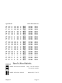
instructions are given how to set the address select, the IRQ
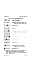
jumper block and the output driver select jumper block. The
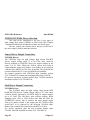
settings of the watch dog timer output are also explained.
The two thirds size Opto DIO48 card will fit into both
long or short slots, in either 8 bit slots or the longer 16 bit slots.
Configuring The Opto DIO48 Card.
_______________________________
In the state it leaves our factory, Opto DIO48 card is ready
to plug straight into an PC computer.
So, unless you have GOOD REASON, you do not need
to alter its default setting.
However, due to the large variety of add-on cards that may
be present in the PC, your Opto DIO48 card may need adjusting
to suit your setup.
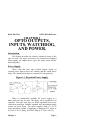
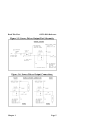
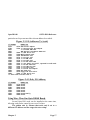
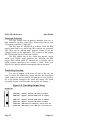
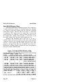
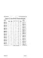
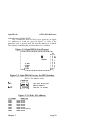
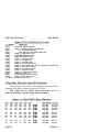
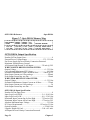
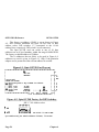
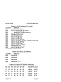
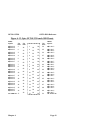
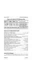
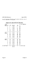
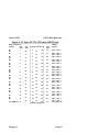
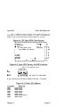
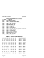
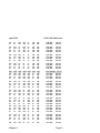
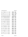
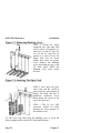
The layout of the Opto DIO48 card is given in Figure 2-1. The
default settings are i/o address 0308Hex, IRQ 7 selected but not
enabled, WATCHDOG VIA PA10 disabled- the PA10 line is
output- and the WATCH DOG OUTPUT OPTIONS, GOODLO
output jumpered to OUT, RESHI output jumpered to BUS. The
source cards have the UDN2984 chips installed and the sink
cards have ULN2803 chips installed.
The Opto DIO48 requires an external power input to power
the output drivers and the isolated side of the opto couplers. On
card power regulation allows the use of external un-regulated
power source, input range 17.5 - 35 Volts. The power supply
input is reverse polarity protected.
Chapter 2
Page 15