1
Opto OUT24
OPTO DIO Reference
range 5 to 50 Volts. Whilst the 2984/81 drivers have built in
output transient suppression diodes, extra diodes are provided on
card the Opto OUT24 card for extra protection. The socketed
10k resistor networks RN14, 16 and 18 should be left installed.
For normal operation, with UDN2984 chips installed, sockets
U30, U28 and U26 contain non inverting buffers chips 74LS541.
For inverse operation, inverting buffers chips 74LS540 should be
installed in sockets U30, U28 and U26.
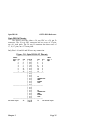
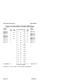
Sink Driver Output Connection._
___________________________
ULN2804 Drivers.
The ULN2804 chips are high voltage, high current NPN
DARLINGTON drivers, output voltage range to 50 Volts, these
could be directly replaced by ULN2824 chips for output voltages
up to 95 Volts. The 2804 have open collector outputs. When
changing from 2984 to 2804 drivers note than the 2804 are
INVERTING drivers, thus to produce the same logical output
from a bit pattern written to the output port the 74LS541 chips
would have to be replaced by the inverting 74LS540 chips.
Remove the socketed 10k resistor networks RN14, 16 & 18.
For inverse operation, then the non inverting buffers chips
74LS541 should be installed in sockets U30, U28 and U26.
Interrupt Selection.
_________________
The Opto OUT24 card can produce interrupts from low to
high transitions on Watch Dog timeout.
The IRQ must be ENABLED in software AND the IRQ
jumper must both be set before any IRQ requests are generated.
Thus IRQs can be enabled under program control to suit the
changing needs of the application. The position of the jumper
MUST match the IRQ level set in the software.
The IRQ enable bits in the watch dog register selects
which Opto OUT24 signal generates the interrupt, the IRQ
jumper block selects which PC interrupt line is asserted, and so
which software interrupt service routine is called. Write your
Chapter 5
Page 57