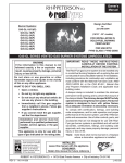
1
Robert H. Peterson Co.
Owner’s
Manual
®
Unregulated Burner
Systems:
DESIGN CERTIFIED
to
RGA - 72
G45-2-18/20(P)
G45-2-24(P)
G45-2-30(P)
GAS FIREPLACE LOG
SET
FOR INSTALLATION IN A SEE-THRU FIREPLACE ONLY
G45-2 SEE-THRU SERIES
Important: Read these instructions carefully before
starting installation of the log set.
WARNING
If the information in this manual is not followed
exactly, a fire or explosion may result, causing
property damage, personal injury, or loss of life.
The Peterson Real-Fyre® gas log set is to be installed
only in a solid-fuel-burning fireplace with a working flue
constructed of noncombustible material. Solid fuels
shall not be burned in a fireplace where this gas log
set is installed. The installation, including provisions
for combustion, ventilation air, and required minimum
permanent vent opening, must conform with the National
Fuel Gas Code (ANSI Z223.1/NFPA 54) and applicable
local building codes. In Canada, the installation must
conform with the Natural Gas and Propane Storage and
Handling Installation Code (CSA-B149.1). A damper
clamp is included to maintain the minimum permanent
vent opening and to prevent full closure of the damper
blade. The chimney damper should be fully opened
when burning the log set.
Do not store or use gasoline or other flammable
vapors and liquids in the vicinity of this or any other
appliance.
WHAT TO DO IF YOU SMELL GAS:
• Open a window.
• Do not try to light any appliance.
• Do not touch any electrical switch; do not use
any phone in the building.
• Immediately call the gas supplier from a
neighbor’s phone. Follow the gas supplier’s
instructions.
• If you cannot reach the gas supplier, call the
fire department.
Important:
Installation and service must be performed
by an NFI Certified or other qualified
professional installer, service agency, or
the gas supplier.
To comply with certification and building
code acceptance, and for safe operation
and proper performance, ONLY Peterson
parts and accessories may be used with
this gas log set.
INSTALLER & CONSUMER
These instructions MUST be retained
with this appliance for future reference.
Robert H. Peterson Co. • 14724 East Proctor Avenue • City of Industry, CA 91746
REV 5 - 0711161227
1
L-A2-22907
TABLE OF CONTENTS
TABLE OF CONTENTS
GENERAL INFORMATION
PARTS LIST
PRE-INSTALLATION AND FIREPLACE PREPARATION SAFETY GUIDELINES
IMPORTANT SAFETY INFORMATION
DAMPER STOP CLAMP INSTRUCTIONS
FOR YOUR SAFETY, READ BEFORE LIGHTING
INSTALLING THE OPTIONAL REAL-FYRE® BURNER SPK & APK SYSTEMS
INSTALLING THE REAL-FYRE® BURNER SPK SYSTEM (Cont.)
INSTALLING THE REAL-FYRE BURNER® SYSTEM (Cont.)
HOW TO INSTALL THE PETERSON REAL-FYRE® GAS LOG SET
LIGHTING INSTRUCTIONS - MANUAL VALVE
EXAMPLE LOG PLACEMENTS
TROUBLESHOOTING YOUR GAS LOG SET
AVAILABLE ACCESSORIES FOR THE GAS BURNER SYSTEM
WARRANTY
2
2
3
4
5
5
5
6
7
8
9
11
12
14
16
18
GENERAL INFORMATION
Keep the area of the gas log set clear and free from combustible materials, gasoline, and other flammable
vapors and liquids.
MAINTENANCE: Periodically remove the logs and examine the burner assembly. If dirty, clean with a stiff
brush. Also, examine the area around the burner air shutter and pilot, removing any dirt
or lint. Occasional cleaning will ensure long life and trouble-free operation. An annual
inspection and cleaning of the vent system by a qualified agency is recommended.
Real- Fyre® G45-2 Series Technical Data Table
(Unregulated)
Burner Air
Shutter
Log
Set
Size
Fire
Box
Width
Fire
Box
Depth
Fire
Box
Height
Min.
Chimney
Height
Vent
Opening
BTU
Natural
BTU
Propane
18/20"
27"
20"
25"
15'
51 sq. in.
75,000
60,000
24"
33"
20"
25"
15'
64 sq. in.
90,000
65,000
30"
39"
20"
25"
15'
64 sq. in.
90,000
80,000
Important:
Fig. 2-1
For safe operation and proper performance of this product, and to comply with certification,
listings, and building code acceptances, use ONLY Peterson Real-Fyre® controls, parts, and
accessories that have been specifically listed or certified for use with this burner system. Use
of other controls, parts, or accessories is prohibited and will void all warranties, certifications,
listings, and building code approvals, and may cause property damage, personal injury, and
loss of life.
WHEN GLASS FIREPLACE ENCLOSURES (DOORS) ARE USED, OPERATE THE GAS LOG SET WITH
THE GLASS DOORS FULLY OPEN.
REV 5 - 0711161227
2
L-A2-22907
GENERAL INFORMATION (Cont.)
The Real-Fyre® gas log set is to be installed only in a
fully vented, noncombustible fireplace with an open
damper. The chimney must be free of any obstructions.
The fireplace must be designed and approved to burn
wood. The fireplace flue must be at least 8" at its
smallest dimension.
The fireplace must have a gas-supply line that has
been installed by a qualified technician in accordance
with all local codes. The gas-supply line must be
1/2" minimum interior diameter. If the gas line to the
fireplace is longer than 20', a larger-diameter line may
be necessary.
Be sure to clean the fireplace floor of any ashes or
other foreign materials. It is recommended that the
fireplace and chimney be inspected by a chimney
sweep or other qualified person before you install the
Real-Fyre® gas log set.
Required Gas Pressure: The minimum inlet gassupply pressure for the purpose of input adjustment
is 7" water column (w.c.) for natural gas and 11"
w.c. for propane gas. The maximum inlet gas-supply
pressure is 10.5" w.c. for natural gas and 13" w.c. for
propane gas.
Testing the Gas-Supply System: The gas log set
and its individual shutoff valve must be disconnected
from the gas-supply piping system while performing
any tests of the piping system at pressures in excess
of 1/2 psig. The gas log set must be isolated from the
gas-supply piping system by closing its individual
manual shutoff valve during any pressure testing of
the gas-supply piping system at test pressures equal
to or less than 1/2 psig. A fireplace screen must be
in place when the log set is burning. When glass
fireplace doors are used, operate the gas log set
with the doors open.
PARTS LIST
Note: Log styles and part sizes will vary, depending upon the G45-2 series log set ordered. When ordering
replacement parts, be sure to indicate the log set size and model. (Model RG5-2-24 Golden Oak
illustrated.)
Item No. Description
3
2
1
4
5
•
10
1.
Bottom log (2) 24"
2.
Top log (2) 15"
3.
Top log (2) 9"
4.
Log locator (2)
5.
Damper clamp
6.
Fireplace grate 24"
7.
Ember burner 24"
8.
Fuel injector
9.
Glowing Embers (2 bags)
10.
Sand for natural gas (2 bags)
or.
Vermiculite for propane gas (2
bags)
11.
Connector kit
Replacement parts are available through
your local Real-Fyre® dealership.
9
7
8
(DRAWINGS NOT TO SCALE)
11
REV 5 - 0711161227
3
L-A2-22907
PRE-INSTALLATION AND FIREPLACE PREPARATION SAFETY GUIDELINES
CAUTION: Installation and repair must be done by an NFI Certified or other qualified, professional
installer. Installer: Carefully read these instructions before installing this gas appliance.
Be sure you understand all safety precautions and warnings contained in this manual.
A. This appliance is designed as an attended appliance. Adults must be present when this gas
appliance is operating. Do not leave this unit burning when unattended or while anyone is
sleeping.
B. This appliance is only for use with the type of gas indicated on the rating plate. This appliance is
NOT CONVERTIBLE for use with other gasses.
C. BE CAREFUL: If not installed, serviced, and used correctly per these instructions, this
product can cause serious personal injury, property damage, or loss of life.
PRE-INSTALLATION AND FIREPLACE PREPARATION SAFETY GUIDELINES
D. WARNING: Before installing in a solid-fuel-burning fireplace, the chimney flue, damper, and firebox
must be thoroughly CLEANED of soot, creosote, ashes, and loose paint, and inspected by a qualified
chimney cleaner. Some older fireplaces may need repair prior to installing this appliance.
E. CHECK GAS TYPE (natural or propane): The gas supply must be the same as stated on your
burner system rating plate. If gas supply is different, DO NOT INSTALL. Contact your dealer for
immediate assistance.
F. Any outside air ducts and/or ash dumps located on the floor or walls of the fireplace must be
permanently sealed shut before the installation. Use a heat-resistant sealant. Do not seal the
chimney flue damper.
G. INSUFFICIENT GAS PRESSURE WILL KEEP THE PILOT FROM OPERATING PROPERLY. DO
NOT USE IF GAS PRESSURE IS LOWER THAN THE MINIMUM REQUIREMENT.
H. The gas piping system must be sized to provide minimum inlet pressure at the maximum flow rate
(BTU/hr). Undue pressure loss will occur if the pipe is too small, or the run is too long.
I. The minimum clearance from the fireplace opening to combustible materials on side walls and
ceiling must be maintained as outlined in MINIMUM CLEARANCE TO COMBUSTIBLES - WALLS
AND CEILING.
J. At least 10"-12" of noncombustible or heat-resistant material is required above the fireplace. A
fireplace hood will be required to act as a heat deflector in protecting combustible fireplace surrounds
(facing and/or mantel) if certain minimum clearances cannot be met.
K. Be certain that combustible flooring material (e.g., carpet, tile, etc.) is not too close to this gas
appliance. If this appliance is at floor level or less than 6" above the floor, there must be at least 12"
of noncombustible material between the base of the fireplace and any combustible flooring.
L. Input ratings shown in BTU per hour are for elevations up to 2,000 ft. For elevations above 2,000 ft.,
refer to the National Fuel Gas Code or contact the Robert H. Peterson Company before installing
this product.
M. The gas log set and its main gas valve must be disconnected from the gas-supply piping system
during any pressure testing of that system at test pressures in excess of 1/2 psig.
N. The gas log set must be isolated from the gas supply piping system by closing the equipment shutoff
valve connected to the gas supply line during any pressure testing of the gas-supply piping system
at test pressures equal to or less than 1/2 psig.
4
IMPORTANT SAFETY INFORMATION
INSTALLATION SAFETY GUIDELINES
A. Before installing in a solid-fuel-burning fireplace, the chimney, flue, and firebox must be cleaned of soot,
creosote, ashes, and loose paint by a qualified chimney cleaner.
B. Carefully inspect the burner and log cartons for shipping damage. If any parts are missing/damaged, call
your dealer. Do not attempt to install the appliance unless all parts are in good condition.
C. If you use Lava Granules for decorative use, do not allow Lava Granules into or on any part of the burner
or on the logs. Lava Granules should only be placed on the floor of the fireplace, in front of and to the sides
of the burner, but away from the controls.
D. Due to high temperatures, the log set should be located out of traffic, away from furniture and draperies.
E. A fireplace screen must be in place when the gas log set is in operation. Unless other provisions for
combustion air are provided, the screen shall have an opening(s) for introduction of combustion air.
F. Connecting directly to an unregulated propane tank can cause an explosion.
G. Special care is required if you are installing the unit into a sunken fireplace. You must raise the fireplace
floor to allow access to gas log controls. This will ensure adequate airflow and guard against sooting. Raise
the fireplace floor using noncombustible materials.
Note: Do not use this log set if any part has been underwater. Immediately call a qualified professional
service technician to inspect the appliance and replace any part of the control system and gas control
that has been underwater.
DAMPER CLAMP INSTRUCTIONS
The damper clamp with set screw (Fig. 5-1) is provided as a means to
prevent full closure of the damper blade. The clamp is easily attached to most
damper blades with pliers or a wrench, and must be permanently installed.
The clamp is designed to prevent accidental closure of the damper when
installed as illustrated (Fig. 5-2 & Fig. 5-3). Should the clamp not fit,
or provide the permanent vent opening listed in the Technical Data Table,
have a permanent stop installed, remove the damper blade,
or have the damper cut to provide the minimum permanent Set screw
opening required.
WARNING
Fig. 5-1
Open
Fig. 5-2
Closed
Fig. 5-3
The fireplace damper must remain completely wide
open when operating the log set.
FOR YOUR SAFETY, READ BEFORE LIGHTING
WARNING
If you do not follow these instructions exactly, a fire or explosion can result, causing property damage,
personal injury, or loss of life.
A. The Peterson Real-Fyre® gas log set has a pilot
that must be lit. When lighting the pilot, follow
these instructions exactly.
C. Use only your hand to push in or turn the gas
control knob. Never use tools. If the knob will
not push in or turn by hand, don’t try to repair it.
Call a qualified professional service technician.
Force or attempted repair may result in a fire or
explosion.
B. BEFORE LIGHTING, smell all around the gas
log set area for gas. Be sure to smell next to the
floor, because some gas is heavier than air and
will settle on the floor.
D. Follow the specific instructions for your burner
model.
WHAT TO DO IF YOU SMELL GAS
Refer to the boxed warning on p. 1 for instructions on what to do if you smell gas.
CAUTION: Burn hazard. Logs will remain hot for some time after use. You must maintain the
log layout as shown to ensure proper operation of your log set. If you need to
reposition any log to maintain the proper layout, use heat-resistant gloves or allow
logs adequate time to cool before handling.
5
INSTALLING THE OPTIONAL REAL-FYRE® BURNER SPK & APK SYSTEMS
Note: We recommend that before you install the log set, you familiarize yourself with the control valve
layout. This will help you to be confident operating the log set when fully installed (see figures
below for typical control positions).
Aluminum tubing
Air mixer/ fuel injector
Check to see if the burner fuel injector or air mixer
is installed on the side of the burner closest to the
Flared
Burner pan
gas connection. The fuel injector or air mixer may be
adapter
mounted at either end of the burner pan. Be sure the
opposite end is capped tightly.
Hearth
elbow
The Real-Fyre® gas log set can be installed using a
number of valve options. Proceed to the appropriate
section identified with the valve option you are using:
Fireplace valve
Manual On/Off
Valve
Section 2
AV Series
Manual Safety Pilot
System
Section 3
SPK Series
Manual Safety Pilot
System
Section 4
APK Series
Remote Safety Pilot
System
Section 1
AV-17 or AV-18 valve
Gas supply line
Fig. 6-2 - AV series
e. Test for leaks at all connections with a soapy
water solution. If bubbles appear, a leak
is present. Turn off the gas and tighten all
connections, then turn on the gas and repeat
the leak test. Repeat until no leaks are detected.
Never use a flame to check for leaks.
Hearth
elbow
Aluminum tubing
f. Turn off the gas supply.
g. Proceed to GRANULE PLACEMENT section.
Burner pan
2. Installing the Real-Fyre® gas log set using a
Peterson manual on/off system (AV series)
(Fig. 6-2)
Air mixer/fuel injector
Gas-supply line
The AV series is an on/off control system for use in
a fireplace not supplied with its own valve. The solid
brass valve is CSA certified. The AV-17 has a knob
handle and extension; the AV-18 has a steel rod
handle. This system requires a match or long-necked
butane lighter to manually ignite the log set.
Connector
elbow
Fig. 6-1 - Fireplace valve
1. Installing the Real-Fyre ® gas log set
using the valve supplied with fireplace
(Fig. 6-1)
a. Attach the hearth elbow to the gas-supply
stub in the fireplace. Use Teflon tape or pipe
compound on the stub. Tighten securely.
a. Attach the hearth elbow to the gas-supply
stub in the fireplace. Use Teflon tape or pipe
compound on the stub. Tighten securely.
b. Attach the AV valve to the fuel injector or air
mixer on the burner pan using the 3/8" elbow
supplied with the AV valve. Use Teflon tape or
pipe compound. Tighten securely.
b. Attach the smaller connector elbow to the
fuel injector or air mixer on the burner pan.
Use Teflon tape or pipe compound. Tighten
securely.
c. Discard the connector elbow of the connector
kit. Be sure the flared adapter supplied with
the AV valve is securely attached to the inlet
side of the valve. Connect the hearth elbow to
the flared adapter with the aluminum tubing.
Tighten both ends securely.
c. Connect the hearth elbow to the connector
elbow with the aluminum tubing. Tighten both
ends securely.
d. Use a long-necked butane lighter, or lay a lighted
match next to the burner pipe and carefully turn
on the gas supply until the burner ignites.
d. Turn off the AV valve and turn on the gas supply
to the fireplace.
To light the gas log set, carefully follow the operating instructions supplied with the
Peterson manual safety pilot kit or Peterson remote safety system.
6
INSTALLING THE REAL-FYRE® BURNER SPK SYSTEM (Cont.)
e. Use a long-necked butane lighter,
or lay a lighted match next to the
burner pipe and carefully turn on the
AV valve until the burner ignites.
Burner pan
Aluminum tubing
Elbow
f. Test for leaks at all connections with
a soapy water solution. If bubbles
appear, a leak is present. Turn off
the gas and tighten all connections,
then turn on the gas and repeat the
leak test. Repeat until no leaks are
detected. Never use a flame to
check for leaks.
Fuel injector
Gas-supply line
SPK valve
SPK
Valve
Note:
SPK 20
g. Turn off the AV valve.
h. Proceed to GRANULE
PLACEMENT section.
The heat shield is not
shown, but must be in
place when operating
the gas log set.
Pressure
tap
Brass
adapter
Fig. 7-1 - SPK-20 system
3. Installing the Real-Fyre® gas log set
using a Peterson manual safety pilot
system (SPK series) (Fig. 7-1 &
Fig. 7-2)
Aluminum tubing
Burner pan
The Peterson SPK control systems makes
enjoying the Real-Fyre ® gas log set
convenient and trouble-free. Just a turn
of the knob (SPK-20, SPK-26, SPK-32,
or SPK-33) or steel rod handle (SPK-21)
allows you to easily ignite or extinguish
the log set. The SPK series is available for
natural or propane gas and will continue to
operate during power failures, as it requires
no outside source of electricity to operate.
Fuel injector
Gas-supply line
SPK valve
SPK -26
SPK valve
PILOT
L
ON
0FF
The valve is CSA certified, and the standing
pilot is adjustable. The built-in safety feature
automatically shuts off the gas flow should
the pilot go out. A convenient pressure tap
is included for easy gas pressure testing.
Advanced heat shielding adds greater
heat protection for cooler, long-lasting
operation.
Elbow
Fig. 7-2 - SPK-26 system
7
INSTALLING THE REAL-FYRE BURNER® SYSTEM (Cont.)
Elbow
Burner pan
Air mixer/fuel injector
Gas-supply line
Air mixer/fuel
injector
Burner pan
Gassupply
line
Aluminum tubing
Aluminum tubing
Hearth
elbow
Adapter
Remote safety valve
Remote safety valve
APK 10
Valve
Note:
Burner
pan
Burner pan
The heat shield is not
shown, but must be in
place when operating
the gas log set.
Note:
APK 11
Valve
Fig. 8-1 - APK-10(P)
The heat shield is not
shown, but must be in
place when operating
the gas log set.
Fig. 8-2 - APK-11(P)
Gas-supply line
Gas-supply line
Burner pan
Air mixer/fuel
injector
Air mixer/fuel
injector
Elbow
Elbow
Aluminum
tubing
Aluminum
tubing
Adapter
Adapter
Remote safety valve
Remote safety valve
Note:
APK- 15 Valve
The heat shield is not
shown, but must be in
place when operating
the gas log set.
Note:
APK- 16 valve
Fig. 8-3 - APK 15(P)
The heat shield is not
shown, but must be in
place when operating
the gas log set.
Fig. 8-4- APK 16(P)
4. Installing the Real-Fyre® gas log set using
a Peterson remote safety pilot system (APK
series) APK-10(P), APK-11(P), APK-15(P),
APK-16(P)
a. Carefully follow the instructions supplied
with the Peterson remote safety system
for the steps to assemble the remote
system and install it on the burner pan.
Peterson remote systems are designed to
provide the ultimate in convenient and reliable
lighting of the Real-Fyre® gas log set. With the
flick of a switch or the push of a button, you
can sit back, relax, and enjoy a comforting
fire. Each APK system includes a control (a
number of options are available), gas valve
(APK valves are CSA and C.G.A. certified
for natural or propane gas), pilot assembly,
heatshield, and APK connector kit.
b. Carefully turn on the gas supply, ignite
the burner pan, and test for leaks at all
connections with a soapy water solution. If
bubbles appear, a leak is present. Turn off
the gas and tighten all connections, turn on
the gas and repeat the leak test. Repeat
until no leaks are detected. Never use a
flame to check for leaks.
c. Turn off the APK system.
d. Proceed to GRANULE PLACEMENT
section of these instructions.
8
INSTALLATION
WARNING: Failure to position the parts in
accordance with these diagrams or
failure to use only parts specifically
approved with this appliance may
result in proper ty damage or
personal injury.
EMBER PLACEMENT
1. Sprinkle embers (PARTS LIST, Item #9)
lightly and evenly over the entire surface of
the granules, making sure that the pilot is not
covered (Fig. 9-2). Center the grate over
the burner pans (Fig. 9-3).
Peterson Real-Fyre® gas logs must be installed
only in a wood-burning fireplace with minimum
venting requirements met (see Technical Data
Table under GENERAL INFORMATION) and with
the damper fully open. Check PARTS LIST to be
sure all parts are included. For safe operation and
proper performance, use only Robert H. Peterson
parts and accessories. Gas-supply pipe must be
1/2". A larger line (3/4") may be required if gas line
is longer than 20'.
2. Place the bottom logs on the grate. The
log locators (PARTS LIST, Item #4) ensure
that adequate space between the logs is
maintained for a clean burn (Fig. 9-3).
3. Position the middle logs per the log option
chosen.
4. Position the top logs per the log option
chosen (Fig. 9-4).
REFER TO PARTS LIST WHEN FOLLOWING
THESE INSTRUCTIONS.
Be sure gas to the fireplace is off when
installing the log set.
1. Remove the grate (Item #6) from the carton
and attach the log locators (Item #4) at
the middle of the grate, positioned per the
illustrations of the log option chosen.
Note: Do not place the grate on the burner
assembly until you have completed
the gas connection and media (sand,
vermiculite, or embers) placement.
Fig. 9-1
(Sand is for natural units only, vermiculite
is for propane units only)
Fig. 9-3
2. Place the burner assembly into the fireplace
and center it.
3. Connect the gas connector kit (PARTS LIST,
Item #11) to the nipple on the regulator and
gas supply of the fireplace and tighten with
a wrench.
4. Turn on the gas to the fireplace and test for
leaks at all connections with a soapy water
solution. If bubbles appear, a leak is present.
Turn off the gas and tighten all connections,
turn on the gas and repeat the leak test.
Repeat until no leaks are detected. Never
use a flame to check for leaks.
Fig. 9-2
SAND OR VERMICULITE PLACEMENT
Fig. 9-4
1. With the burner off, fill the burner pans
completely with sand or vermiculite (PARTS
LIST, Item #10). Slope the media at the same
angle as the burner pan (see Fig. 9-1).
9
DR
AF
T
This page
ge intentionally
intentio
left blank.
10
LIGHTING INSTRUCTIONS - MANUAL VALVE
FOR YOUR SAFETY, READ BEFORE LIGHTING
WARNING
If you do not follow these instructions exactly, a fire or explosion may result, causing property
damage, personal injury, or loss of life.
Do not use this appliance if any part has been underwater. Immediately call for a qualified professional
service technician to inspect the appliance and to replace any part of the control system and any gas control
that has been underwater.
The Real-Fyre® burner system has a pilot that can be lit by hand using a match or lighter. When lighting the
pilot, follow these instructions exactly.
BEFORE LIGHTING, smell all around the burner area for gas. Be sure to smell next to the floor, as some gas
is heavier than air and will settle on the floor. IF YOU SMELL GAS, FOLLOW THE INSTRUCTIONS ON P. 1.
Use only your hand to push in or turn the gas control knob. Never use tools. If the knob will not push in or turn
by hand, don't try to repair it. Call a qualified professional service technician. Force or attempted repair may
result in fire or explosion.
LIGHTING THE LOG SET
Important:
Keep the gas log burner area free from combustible materials, gasoline, and other flammable
vapors.
1. Be sure chimney damper is fully open.
2. To light the log set with the fireplace valve, lay a lighted match on the surface of the burner embers
(granules) near the gas inlet (Fig. 11-1). DO NOT HOLD THE MATCH IN YOUR HAND. Turn on the gas
slowly. Burner should light.
3. If a safety pilot is used, see the safety pilot instruction sheet.
4. If an APK system is used, see APK instructions.
Fig. 11-1
Observe the flames. The main burner flames should be blue at the base and a combination of blue/yellow
at the body and at the tips. They should be 5" to 8" above the logs, with the center flame being the tallest
(see cover photo). Front flames in the ember burner should be 1/4" above the embers.
11
EXAMPLE LOG PLACEMENTS
GOLDEN OAK
GOLDEN OAK
GOLDEN OAK
12
EXAMPLE LOG PLACEMENTS
SPLIT LOG
SPLIT LOG
DRIFTWOOD (G4 ONLY)
13
TROUBLESHOOTING YOUR GAS LOG SET
SYMPTOM
1. Excessive smoking and
sooting
2. Low flame
CAUSE
SOLUTION
A. Poor draft or downdraft
A. Check for chimney blockage.
Be sure chimney is at least
3' taller than anything within
10' of it in all directions. If not,
consult a chimney sweep.
Chimney cap or fan may help.
Under severe conditions, you
may need to open a window
near the fireplace about 1" to
2" when burning the log set.
B. Improper burner for gas used
B. Use only a natural-gas set
with natural gas. Use only a
propane-gas set with propane
gas.
C. Damper closed
C. Open the damper fully when
operating the gas log set.
D. Improper log placement
D. Be sure the bottom logs are
spaced at least 3" apart. Top
logs should be placed to
minimize flame impingement.
E. Flue is less than 8" in diameter
E. Remove the burner and log
set because of inadequate
fireplace ventilation.
F. Air mixer on propane set is
closed
F. O p e n t h e
completely.
A. Incorrect log set for type of gas
used
A. Consult your dealer for proper
set.
B. Insufficient gas supply
B. Other gas appliances may
be competing for gas supply.
Consult installer or plumber.
Orifice size is based upon
7" w.c. pressure for natural
gas and 11" w.c. pressure for
propane gas. Plumbing must
supply adequate pressure.
C. Blockage or kink in connector
kit, plumbing, or burner orifice
C. Clean out blockage. If connector
kit is kinked, replace it.
D. Valve not fully open
D. Open valve fully.
14
air
mixer
TROUBLESHOOTING YOUR GAS LOG SET (Cont.)
SYMPTOM
3. Uneven flame distribution
(Lower at one end of the
burner)
4. Flame at air mixer
(For propane units)
CAUSE
SOLUTION
A. Clogged or blocked portholes
A. Portholes can be cleared of
foreign object by running a wire
through them.
B. Insufficient gas pressure and/or
supply
B. Consult installer or plumber.
(See solution 2b.)
C. Granules may be packed down
too tightly
C. Loosen granules around burner
pipe by running a kitchen knife
along both sides of pipe. Even
out granules in burner pan.
D. Auxiliary shutoff valve partially
closed
D. Open valve fully. Usually, you will
find this along the wall 3' from the
fireplace.
A. Clogged or blocked portholes
A. Portholes can be cleared of
foreign object by running a wire
through them.
B. Insufficient gas pressure and/or
supply
B. Consult installer or plumber.
(See solution 2b.)
C. Granules may be packed down
too tightly
C. Loosen granules around the
burner by running a kitchen knife
along both sides of the pipe. Be
sure vermiculite (not sand) is
used with an air mixer.
D. Excessive gas pressure
D. Contact your gas supplier.
15
AVAILABLE ACCESSORIES FOR THE GAS BURNER SYSTEM
The following accessories are available for burner systems as indicated, and can be purchased separately
from your local Peterson Real-Fyre® dealer. Before purchasing, make sure the accessory you desire is
compatible with your specific model (for example, VR-2A is used with the Series 15 systems). To install
and operate any accessory, simply follow the instructions supplied with your accessory kit.
Note: Photos not to scale
FOR SERIES 15: REMOTE TRANSMITTERS AND RECEIVERS
FOR VARIABLE FLAME-HEIGHT CONTROL
(FOR USE WITH SERIES 15 VALVES) AND FOR NATURAL OR PROPANE GAS
VR-1A
VR-2A
RVF-1
Transmitter handset,
receiver, handset
holder, and wiring
Transmitter handset,
receiver, handset holder,
wall switch, and wiring
Transmitter handset,
receiver, and wiring
FOR SERIES 15: WS-3 WALL SWITCH
THE WS-3 SWITCH OPERATES FLAME-HEIGHT CONTROL KNOB ON SERIES 15 VALVES
Switch to
valve wiring
Cover
screws
=
=
Wall switch
cover
Battery
holder
Flame-height control
knob will rotate
clockwise.
Flame-height control
knob will rotate
counterclockwise.
Press LOW/OFF to
decrease flame height
or turn unit off.
Press HI/ON to turn unit on
or increase flame height.
FOR SERIES 16: WS-4 WALL SWITCH
Cover
screws
Switch to
valve wiring
Wall switch
cover
THE WS-4 SWITCH OPERATES THE
FLAME-HEIGHT CONTROL KNOB
Press ON to
ignite the main
burner.
Battery
holder
Press OFF to
extinguish the
main burner.
16
AVAILABLE ACCESSORIES FOR THE GAS BURNER SYSTEM (Cont.)
FOR SERIES 01, 10, 11, and 12: ON/OFF REMOTES AND RECEIVERS
BATTERY-OPERATED REMOTE LIGHTING SYSTEMS FOR USE WITH
NATURAL OR PROPANE GAS
RR-2A RR-2A
RR-1A
RUS-1
Transmitter handset,
Transmitter handset,
receiver, wall switch,
Transmitter
receiver,
handsethandset,
holder, receiver,and wiring
holder,
wall switch, and wiring.
wall handset
switch, and
wiring
RUS-1
Transmitter handset,
Transmitter handset,
receiver.
receiver
PC-105/PC-106 PINE CONE REMOTE
BATTERY-OPERATED REMOTE LIGHTING SYSTEM WITH DECORATIVE
PINE CONE RECEIVER FOR USE WITH NATURAL OR PROPANE GAS
PC-105 Remote transmitter
(for use with Series 01,
10, 11, and 12)
Pine cone
receiver
PC-106 Remote transmitter
(for use with Series 16)
FOR SERIES 01, 10, 11, and 12: WS-1 AND WS-2 WALL SWITCHES
WS-1 SWITCH: CONTROLS BURNER SYSTEM LIGHTING AND SHUTDOWN
WS-2 TIMER WALL SWITCH: CONTROLS OPERATING TIME (UP TO 60 MIN.)
Mechanical timer (WS-2)
Wall switch (WS-1)
17
WARRANTY
PETERSON VENTED GAS LOG SETS
LIMITED WARRANTY
All Peterson gas logs are WARRANTED for as long as you own them (lifetime).
All Peterson burner assemblies are WARRANTED for TEN (10) YEARS.
SPK-26 controls are covered by a THREE (3) YEAR “All Parts” Warranty.
All other Peterson valves, pilots, and controls are covered by a ONE (1) YEAR Limited Warranty (excluding batteries).
PLEASE KEEP A COPY OF YOUR SALES SLIP FOR PROOF OF PURCHASE
This warranty applies to the original purchaser and to single family residential use only. It commences from date of purchase, and is valid only with
proof of purchase.
This warranty does not cover parts becoming defective through misuse, accidental damage, electrical damage, improper handling, storage, and/or
installation. Product must be installed (and gas must be connected) as specified in the instructions or operator’s manual, by a qualified professional
installer. Accessories, parts, valves, remotes, etc., when used must be Peterson Co. product.
This warranty does not apply to rust, corrosion, oxidation, or discoloration, unless the affected component becomes inoperable. It does not cover
labor or labor-related charges.
This warranty specifically excludes liability for indirect, incidental, or consequential damages. Some states do not allow the exclusion or limitation of
incidental or consequential damages, so the above exclusion may not apply to you. This warranty gives you specified legal rights, and you may have
other rights that may vary from state to state.
For additional information regarding this warranty, or to place a warranty claim, contact the R.H. Peterson dealer where the product was purchased.
ROBERT H. PETERSON CO.
Quality Check
Date:___________
Orifice # (Main):__________
Orifice # (Other):__________
Leak Test:
___________
Burn Test:
___________
Gas Type:
NAT. / PROPANE
Model #:
___________
Serial #:
___________
Air Shutter: ___________
Inspector: ___________
Robert H. Peterson Co. • 14724 East Proctor Avenue • City of Industry, CA 91746
18