1
Acer | HDS AMS200
User and Reference Guide
MK-95DF713-03
2006 Hitachi Data Systems Corporation, ALL RIGHTS RESERVED
Notice: No part of this publication may be reproduced or transmitted in any form or by any
electronic or mechanical means, including photocopying and recording, or stored in a
database or retrieval system for any purpose without the express written permission of
Hitachi Data Systems Corporation (hereinafter referred to as “Hitachi Data Systems”).
Hitachi Data Systems reserves the right to make changes to this document at any time
without notice and assumes no responsibility for its use. Hitachi Data Systems products and
services can only be ordered under the terms and conditions of Hitachi Data Systems’
applicable agreements. All of the features described in this document may not be currently
available. Refer to the most recent product announcement or contact your local Hitachi
Data Systems sales office for information on feature and product availability.
This document contains the most current information available at the time of publication.
When new and/or revised information becomes available, this entire document will be
updated and distributed to all registered users.
Trademarks
Hitachi Data Systems is a registered trademark and service mark of Hitachi, Ltd., and the
Hitachi Data Systems design mark is a trademark and service mark of Hitachi, Ltd.
TagamaStore is a trademark of Hitachi Data Systems Corporation.
Egenera and BladeFrame are registered trademarks of Egenera, Inc.
Emulex is a registered trademark of Emulex Corporation.
HP-UX, MC/ServiceGuard, and Tru64 are trademarks or registered trademarks of the
Hewlett-Packard Development Company, L.P.
AIX and RS/6000 are registered trademarks of International Business Machines Corporation.
Pentium is a registered trademark of Intel Corporation.
Linux is a registered trademark of Linus Torvalds.
Microsoft, Windows, and Windows NT are registered trademarks of Microsoft Corporation.
Netscape and Netscape Navigator are registered trademarks of Netscape Communications
Corporation in the U.S. and other countries.
NetWare is a registered trademark of Novell, Incorporated.
Oracle is a registered trademark of Oracle Corporation.
QLogic is a registered trademark of QLogic Corporation.
Java, Solaris, Sun, Sun Enterprise, and Sun Fire are trademarks of Sun Microsystems, Inc.
Acer | HDS AMS200 User and Reference Guide
iii
VERITAS is a trademark of VERITAS Software Corp.
All other brand or product names are or may be registered trademarks, trademarks, or
service marks of and are used to identify products or services of their respective owners.
Notice of Export Controls
Export of technical data contained in this document may require an export license from the
United States government and/or the government of Japan. Please contact the Hitachi Data
Systems Legal Department for any export compliance questions.
Document Revision Level
Revision
Date
Description
MK-95DF713-00
June 2005
Initial Release
MK-95DF713-01
September 2005
Revision 1, supersedes and replaces MK-95DF713-00
MK-95DF713-02
November 2005
Revision 2, supersedes and replaces MK-95DF713-01
MK-95DF713-03
January 2006
Revision 3, supersedes and replaces MK-95DF713-02
Source Document(s) for this Revision
Acer | HDS Adaptable Modular Storage 200 User and Reference Guide
Changes in this Revision
iv
Changed the introduction to Chapter 1
Changed the introduction to Chapter 2
Changed the introduction to Chapter 3
Changed the introduction to Chapter 4
Changed Figure 4.1
Changed Figure 4.2
Changed Figure 4.3
Changed Figure 4.4
Changed Figure 4.5
Changed Figure 4.6
Changed section 4.4
Added section 4.5
Added section 4.5.1
Preface
Changed Table 4.1
Changed Figure 4.16
Changed Table 4.11
Changed Figure 4.25
Changed Table 4.20
Changed the introduction to Chapter 5
Changed section 4.5.1
Changed section 5.4
Added section 5.10
Changed Figure 5.1
Added Figure 5.2
Changed Figure 5.3
Changed section 5.5.2
Changed section 5.6.2
Changed the introduction to Chapter 6
Changed section 6.1
Changed section 6.1.1
Changed Figure 6.1
Added section 6.1.4
Added Figure 6.4
Changed the introduction to Chapter 7
Added section 7.3
Added section 7.6
Added section 7.7
Changed step 2 of section 7.11.1
Changed step 2 of section 7.11.2
Changed step 8 of section 7.17
Changed the introduction to Chapter 8
Added section 8.7
Added section 8.8
Changed the introduction to the Appendices
Changed Table B.1
Changed Table C.1
Acer | HDS AMS200 User and Reference Guide
v
vi
Preface
Preface
This document describes the physical, functional, and operational characteristics of the
AMS200 subsystem. This document also provides operation instructions, installation details,
and configuration planning information for the AMS200 subsystem.
This User and Reference Guide assumes:
The user is familiar with the Acer | HDS AMS200™ array subsystem, and
The user is familiar with the Windows® 95, Windows® 98, Windows® 2000, or
Windows NT® operating systems. These versions are abbreviated to Windows in this
document.
This subsystem complies with FDA radiation performance standards 21CFR, subchapter J.
Notes:
For further information, please contact your Hitachi Data Systems account team, or visit
the Hitachi Data Systems worldwide web site at http://www.hds.com.
The use of Acer | HDS AMS200 subsystem and all other Hitachi Data Systems products is
governed by the terms of your agreement(s) with Hitachi Data Systems.
Software Version
This document revision applies to Acer | HDS Adaptable Modular Storage and Workgroup
Modular Storage Products version 2.0 and higher.
EMI Regulation
This equipment has been tested and found to comply with the limits for a Class A digital
device, pursuant to Part 15 of the FCC Rules. These limits are designed to provide
reasonable protection against harmful interference when the equipment is operated in a
commercial environment. This equipment generates, uses, and can radiate radio frequency
energy and, if not installed and used in accordance with the instruction manual, may cause
harmful interference in which case the user will be required to correct the interference at
his own expense. Testing was done with shielded cables. Therefore, in order to comply with
the FCC regulations, you must use shielded cables with your installation.
Acer | HDS AMS200 User and Reference Guide
vii
If trouble occurs in a different configuration, the user may be requested to take appropriate
preventive measures. The EMI test was done in the following configuration:
AMS200-RKS+H1J
AMS200-RKS+RKAJ+H2J
Convention for Storage Capacity Values
This document uses the following convention for storage capacity values:
1 KB (kilobyte) = 1,000 bytes
1 MB (megabyte) = 1,000,000 bytes
1 GB (gigabyte) = 1,000,000,000 bytes
1 TB (terabyte) = 1,000 Gbytes
Referenced Documents
Acer | HDS Adaptable Modular Storage and Workgroup Modular Storage Cache Residency
Manager Software User’s Guide
Acer | HDS Adaptable Modular Storage and Workgroup Modular Storage Navigator Modular
Graphical User Interface (GUI) User’s Guide
Acer | HDS Adaptable Modular Storage and Workgroup Modular Storage Navigator Modular
Command Line Interface (CLI)
Acer | HDS Adaptable Modular Storage and Workgroup Modular Storage ShadowImage™ InSystem Replication Software User’s Guide
Acer | HDS Adaptable Modular Storage and Workgroup Modular Storage TrueCopy™
Synchronous Remote Replication Software User’s Guide
Acer | HDS Adaptable Modular Storage and Workgroup Modular Storage Copy-on-Write
SnapShot User’s Guide
Acer | HDS AMS200 and WMS100 Global 19-Inch Rack Reference Guide
Acer | HDS Adaptable Modular Storage and Workgroup Modular Storage Performance
Monitor Software User’s Guide
viii
Preface
Acer | HDS AMS200 User and Reference Guide
ix
Contents
Chapter 1
Overview of the AMS200 Subsystem ....................................................................................1
1.1
1.2
1.3
Chapter 2
Planning for Installation and Operation................................................................................9
2.1
2.2
2.3
2.4
Chapter 3
User Responsibilities ...........................................................................
Safety Precautions .............................................................................
2.2.1 Symbol Marks...........................................................................
2.2.2 Repair, Modification, and Disassembly.............................................
2.2.3 Precautions for Using Equipment ...................................................
2.2.4 Inspection and Cleaning Precautions ...............................................
2.2.5 Emergency Precautions...............................................................
2.2.6 Warning Notices .......................................................................
2.2.7 Warning Label Locations .............................................................
General Specifications and Requirements ..................................................
2.3.1 Dimensions and Weight ...............................................................
2.3.2 Service Clearance Requirements....................................................
2.3.3 Floor Load Rating......................................................................
2.3.4 Internal Logic Specifications.........................................................
2.3.5 Cable Function .........................................................................
Environmental Specifications and Requirements ..........................................
2.4.1 Environmental Hazards ...............................................................
2.4.2 Temperature and Humidity Requirements ........................................
2.4.3 Input Power and Insulation Performance Specifications ........................
2.4.4 Air Flow Requirements ...............................................................
2.4.5 Vibration and Shock Tolerances.....................................................
2.4.6 Reliability...............................................................................
11
12
13
13
14
18
19
20
20
26
26
28
29
30
30
31
31
32
32
34
34
35
Powering On/Off Procedure.................................................................................................39
3.1
3.2
Chapter 4
Overview Features ............................................................................... 2
1.1.1 High Data Availability................................................................... 2
1.1.2 Connectivity.............................................................................. 2
1.1.3 Scalability ................................................................................ 3
1.1.4 Performance Reporting and Monitoring.............................................. 3
1.1.5 Reliability, Availability, and Serviceability ......................................... 4
1.1.6 Hitachi Freedom Storage™ and Hitachi Freedom Data Networks™ .............. 5
Rack-Mount Model ................................................................................ 6
Floor Model ........................................................................................ 7
AMS200 Rack-Mount Model ....................................................................
3.1.1 Subsystem Power On ..................................................................
3.1.2 Subsystem Power Off .................................................................
3.1.3 Subsystem Power Off .................................................................
AMS200 Floor Model ............................................................................
3.2.1 Subsystem Power On ..................................................................
3.2.2 Subsystem Power Off .................................................................
40
40
41
41
43
43
44
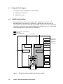
Subsystem Architecture and Components ........................................................................45
4.1
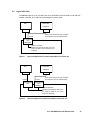
Configuration Block Diagrams ................................................................ 46
Acer | HDS AMS200 User and Reference Guide
xi
4.2
4.3
4.4
4.5
4.6
4.7
Chapter 5
46
52
58
59
60
62
62
64
65
65
65
66
68
70
71
73
75
78
82
Functional and Operational Characteristics ......................................................................93
5.1
5.2
5.3
5.4
5.5
5.6
5.7
5.8
5.9
xii
4.1.1 AMS200 Rack-Mount Model ...........................................................
4.1.2 AMS200 Floor Model ...................................................................
Redundant Power Supplies ....................................................................
Fibre Channel Interface .......................................................................
4.3.1 Mini-HUB59
4.3.2 Connection Specifications............................................................
4.3.3 Fibre Channel Configuration.........................................................
4.3.4 Attention to the Host Direct Connection for AMS200 ............................
NAS Interface....................................................................................
ISCSI Interface ..................................................................................
4.5.1 Setting iSCSI Information.............................................................
Array Frame .....................................................................................
4.6.1 AMS200 Rack-Mount Model ...........................................................
4.6.2 Floor Model .............................................................................
Component Names, Locations, and Functions .............................................
4.7.1 Front Bezel Component Locations and Functions ................................
4.7.2 Component Locations .................................................................
4.7.3 Switch Locations and Functions .....................................................
4.7.4 Connector Locations and Functions ................................................
4.7.5 LED Locations and Functions ........................................................
Contents
New AMS200 Features and Capabilities ..................................................... 95
Raid Implementations.......................................................................... 96
Cache Management............................................................................. 98
Logical Units (LUs).............................................................................. 99
Open Systems Features and Functions ..................................................... 101
5.5.1 Open Systems Middleware .......................................................... 101
5.5.2 Logical Unit Mapping................................................................. 101
Data Management Features and Functions ................................................ 102
5.6.1 Cache Residency Manager Function ............................................... 102
5.6.2 LUN Manager Function............................................................... 102
5.6.3 Data Retention Utility Function.................................................... 102
5.6.4 LUN Expansion Function ............................................................. 103
5.6.5 Password Protection Function ...................................................... 103
Copy Solution Features and Functions ..................................................... 103
5.7.1 ShadowImage In-System Replication Function................................... 103
5.7.2 Copy-On-Write Snapshot Function ................................................. 103
5.7.3 NAS Backup Restore Modular Function ............................................ 104
5.7.4 NAS SyncImage Modular Function .................................................. 104
Performance Management Features and Functions ...................................... 105
5.8.1 Performance Monitor Function ..................................................... 105
5.8.2 Cache Partition Manager Function................................................. 105
NAS Features and Functions ................................................................. 106
5.9.1 NAS Data Control Modular Function ............................................... 106
5.9.2 NAS File Sharing Modular Function ................................................ 106
5.9.3 NAS Manager Modular Function .................................................... 106
5.9.4 NAS Backup Restore Modular Function ............................................ 106
5.9.5 NAS SyncImage Modular Function .................................................. 106
5.9.6 NAS Anti-Virus Agent Modular Function........................................... 106
5.10 iSCSI Features and Functions ................................................................ 107
5.10.1 CHAP Authentication................................................................. 107
5.10.2 iSNS Client ............................................................................. 107
Chapter 6
Configuring the AMS200 Subsystem ................................................................................109
6.1
6.2
6.3
6.4
6.5
6.6
Chapter 7
Overview of Configuration ................................................................... 110
6.1.1 Open Systems Configuration ........................................................ 110
6.1.2 Defining LUNs ......................................................................... 110
6.1.3 Fibre Channel Interface Addressing ............................................... 111
6.1.4 iSCSI Interface Addressing .......................................................... 113
6.1.5 Alternate Pathing..................................................................... 114
6.1.6 NAS Configuration .................................................................... 116
Configuring LAN Interfaces of the AMS200 Subsystem ................................... 117
Configuring the AMS200 Subsystem ......................................................... 118
Registering the AMS200 Subsystem for Control by Storage Navigator-Modular ...... 119
Configuring the AMS200 Subsystem for the Desired Application ....................... 120
AMS200 Subsystem General Configuration................................................. 121
Configuring Storage on the AMS200 Subsystem ............................................................123
7.1
7.2
7.3
7.4
7.5
7.6
7.7
Software Composition ........................................................................ 125
7.1.1 Microprogram ......................................................................... 125
7.1.2 System Parameters................................................................... 125
7.1.3 Configuration Information .......................................................... 125
7.1.4 SNMP Information .................................................................... 125
7.1.5 Storage for Parameters.............................................................. 126
Setting Fibre Channel Information.......................................................... 127
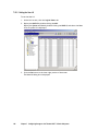
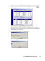
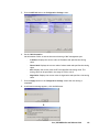
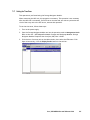
Setting iSCSI Information ..................................................................... 129
7.3.1 Setting iSCSI Port Information...................................................... 129
7.3.2 Setting the iSNS Server Information ............................................... 130
7.3.3 Sending a Ping ........................................................................ 131
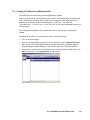
Determining Space and RAID Level Requirements........................................ 133
7.4.1 Setting a Spare Disk .................................................................. 134
7.4.2 Canceling a Spare Disk Setting ..................................................... 137
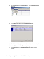
7.4.3 Setting a RAID Group................................................................. 138
7.4.4 Deleting a RAID Group ............................................................... 141
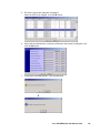
7.4.5 Setting a Logical Unit ................................................................ 143
7.4.6 Deleting the Last Logical Unit ...................................................... 144
7.4.7 Formatting a Logical Unit ........................................................... 146
7.4.8 Changing the Format Mode ......................................................... 150
7.4.9 Changing the Default Controller in Charge of an LU............................ 152
Setting Host Group Information ............................................................. 153
7.5.1 Setting Mapping Information ....................................................... 153
Setting Target Information................................................................... 157
7.6.1 Changing the Target Information .................................................. 157
7.6.2 Initializing the Target 0 ............................................................. 159
7.6.3 Setting Mapping Information ....................................................... 160
Setting CHAP Authentication ................................................................ 164
7.7.1 Adding a CHAP User .................................................................. 164
7.7.2 Changing the CHAP User ............................................................ 165
Acer | HDS AMS200 User and Reference Guide
xiii
7.8
7.9
7.10
7.11
7.12
7.13
7.14
7.15
7.16
7.17
Chapter 8
Troubleshooting .................................................................................................................205
8.1
8.2
8.3
8.4
xiv
7.7.3 Deleting the CHAP User ............................................................. 167
7.7.4 Changing the Two-Way Authentication Information ............................ 168
Transferring Configurations from One Array to Another ................................ 170
Storing Configuration Data ................................................................... 171
7.9.1 System Parameter Information..................................................... 171
7.9.2 RAID Group/LU information ........................................................ 172
7.9.3 Port/Host Group Information....................................................... 173
7.9.4 NAS System LU/User LU Information .............................................. 174
Applying Configuration Data to another AMS200 Subsystem............................ 175
7.10.1 System Parameters................................................................... 175
7.10.2 RAID Group/Logical unit............................................................. 176
7.10.3 Port/Host Group ...................................................................... 177
Setting Host Connection Parameters ....................................................... 178
7.11.1 Simple Setting ........................................................................ 178
7.11.2 Detailed Setting for Each Host Connection....................................... 184
Setting the Subsystem when using Special Mode ......................................... 185
Changing the Network Parameter........................................................... 187
Changing the IP Address for the Maintenance Port ...................................... 189
Setting the System LU and User LU in the NAS System .................................. 193
7.15.1 Setting the System LU ............................................................... 194
7.15.2 Setting the User LU .................................................................. 196
Setting the NNC Management LAN Port Information in the NAS System .............. 198
Setting the Time Zone ........................................................................ 201
Contents
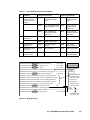
Troubleshooting Based on LED Indications ................................................ 208
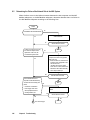
8.1.1 The POWER LED Does Not Turn on................................................. 208
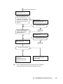
8.1.2 The POWER LED Turned Off ........................................................ 209
8.1.3 If the READY LED Does Not Turn On or has Turned On Once then Off ....... 210
8.1.4 The Alarm LED Turned On........................................................... 211
8.1.5 The WARNING LED has Turned on or Blinks ...................................... 211
8.1.6 The WARNING LED Has Turned On or Blinks...................................... 213
Web Overview.................................................................................. 214
8.2.1 Operational Environment ........................................................... 214
8.2.2 Characteristics of Network Functions When Connecting with the Web...... 217
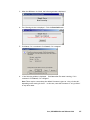
Web Operational Procedures ................................................................ 218
8.3.1 Connecting to the Network using a LAN Interface .............................. 218
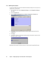
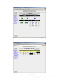
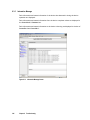
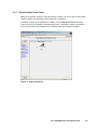
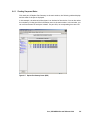
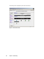
8.3.2 Screen Outlines ....................................................................... 219
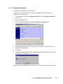
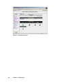
8.3.3 Main Screen in Normal Mode ....................................................... 223
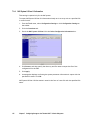
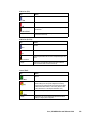
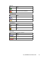
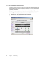
8.3.4 Status Display of Replaceable Components ...................................... 226
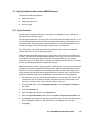
8.3.5 Information Message ................................................................. 234
8.3.6 Setting the Buzzer Sound Volume.................................................. 235
8.3.7 Clear Specified Factors of NNC Partial Alarm.................................... 236
Troubleshooting Using a Web Connection ................................................. 239
8.4.1 Checking Subsystem Status ......................................................... 239
8.4.2 Checking the Progress Condition Display ......................................... 240
8.4.3 Checking Component Status ........................................................ 241
8.4.4 Checking Log Messages .............................................................. 243
8.4.5 Troubleshooting Using Messages ................................................... 245
8.4.6 Reading Failure Information ........................................................ 251
8.5
8.6
8.7
8.8
Chapter 9
Determining the Failure of the Network Side in the NAS System ...................... 254
Connecting Failure in Connection with the Web ......................................... 256
8.6.1 Collecting Simple Trace ............................................................. 256
8.6.2 NAS Log Collection ................................................................... 258
8.6.3 NAS Dump Generation ............................................................... 262
Determining Failure on the Network Side of an iSCSI System .......................... 268
Calling the Acer | HDS Support Center .................................................... 270
Periodic Maintenance.........................................................................................................271
Appendix A Glossary ..............................................................................................................................275
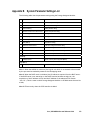
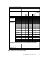
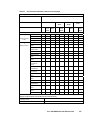
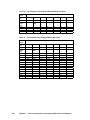
Appendix B System Parameter Settings List........................................................................................279
Appendix C Basic Specifications of the Subsystem ............................................................................291
Appendix D Interfaces ............................................................................................................................297
D.1
D.2
Fibre Channel Connection Specifications .................................................. 297
Ethernet Connection Specifications ........................................................ 325
Appendix E Remote Adapter Specifications.........................................................................................327
E.1
E.2
Remote Adapter Specifications.............................................................. 327
Remote Adapter Dimensions ................................................................. 328
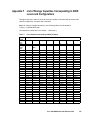
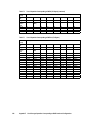
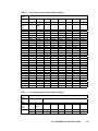
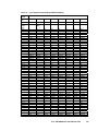
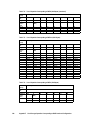
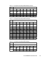
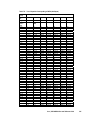
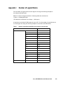
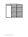
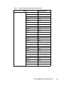
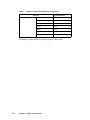
Appendix F List of Storage Capacities Corresponding to RAID Levels and Configurations ...........329
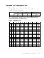
Appendix G Port Address Mapping Table .............................................................................................347
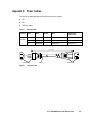
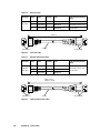
Appendix H Power Cables ......................................................................................................................351
Appendix I Number of Logical Blocks .................................................................................................353
Appendix J Using LUN Security or LUN Management on a Fabric Switch Connection ...................359
J.1
J.1
When an FC Interface Board is Not Added to the Control Unit......................... 359
When an FC Interface Board is Added to the Control Unit.............................. 360
Acer | HDS AMS200 User and Reference Guide
xv
List of Figures
Figure 2.1
Figure 2.2
Figure 2.3
Figure 2.4
Figure 2.5
Figure 3.1
Figure 4.1
Figure 4.2
Figure 4.3
Figure 4.4
Figure 4.5
Figure 4.6
Figure 4.7
Figure 4.8
Figure 4.9
Figure 4.10
Figure 4.11
Figure 4.12
Figure 4.13
Figure 4.14
Figure 4.15
Figure 4.16
Figure 4.17
Figure 4.18
Figure 4.19
Figure 4.20
Figure 4.21
Figure 4.22
Figure 4.23
Figure 4.24
Figure 4.25
Figure 4.26
Figure 4.27
Figure 4.28
Figure 4.29
Figure 4.30
Figure 4.31
Figure 4.32
Figure 4.33
Figure 4.34
Figure 4.35
Figure 4.36
xvi
Contents
Positions and Contents of Labels on Floor Model RKS+H1HJ....................... 21
Positions and Contents of Labels on Rack-Mount Model RKS+RKAJ+H2J......... 22
Positions and Contents of Labels on Rack-Mount Model RKS ...................... 23
Positions and Contents of Labels on Rack-Mount Model RKNAS ................... 24
Positions and Contents of Labels on Rack-Mount Model RKAJ/RKAJAT .......... 25
Subsystem Power On/Off (Example: Floor [RKS+ RKAJ+H2J)...................... 43
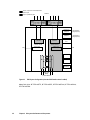
RKS System Configuration (When Interface board is not added) ................. 46
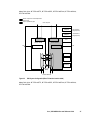
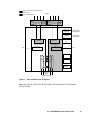
RKS System Configuration (When FC Interface board is added).................. 47
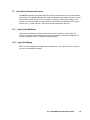
RKS System Configuration (when the iSCSI Interface board is added) .......... 48
RKS and RKNAS System Configuration ................................................ 49
RKAJ System Configuration ............................................................. 50
RKAJAT System Configuration .......................................................... 51
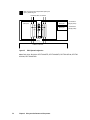
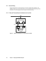
Floor (RKS+H1J) Model AMS200 System Configuration (When FC Interface board
is not added) .............................................................................. 52
Floor (RKS+H1J) Model AMS200 System Configuration (When FC Interface board
is added) ................................................................................... 53
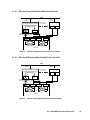
Floor (RKS+H1J) Model AMS200 System Configuration (When iSCSI Interface
board is added) ........................................................................... 54
Floor (RKS+RKAJ+H2J) Model AMS200 System Configuration (When Interface
board is not added) ...................................................................... 55
Floor (RKS+RKAJ+H2J) Model AMS200 System Configuration (When FC Interface
board is added) ........................................................................... 56
Floor (RKS+RKAJ+H2J) Model AMS200 System Configuration (When iSCSI
Interface board is added) ............................................................... 57
AMS200 FC Connector.................................................................... 59
RKS, RKA, and RKA/RKAJAT Front Bezel Component Locations .................. 71
RKNAS Front Bezel Component Locations ............................................ 72
RKS Component Locations.............................................................. 73
RKAJ Component Locations ............................................................. 73
RKAJAT Component Locations.......................................................... 73
Panel Assembly Switch Location ....................................................... 75
Backup Battery Unit Switch Location ................................................. 76
Power Unit Switch Locations ........................................................... 76
RKNAS Switch Locations ................................................................. 77
ENC Unit Connector Locations......................................................... 78
Power Unit Connector Locations ...................................................... 79
Control Unit Connector Locations..................................................... 80
RKNAS Connector Locations............................................................ 81
Disk Drive Display LED Locations ...................................................... 82
Disk Drive Display (RKAJ., RKAJAT) LED Locations ................................. 84
Battery Backup Unit LED Locations ................................................... 84
ENC Unit LED Locations................................................................. 85
SENC Unit LED Locations ................................................................ 86
Power Unit LED Locations .............................................................. 87
Fan Assembly LED Locations ............................................................ 87
Control Unit LED Locations............................................................. 88
RKNAS LED Locations (front)........................................................... 90
RKNAS LED Locations (rear)............................................................ 91
Figure 5.1
Figure 5.2
Figure 5.3
Figure 5.4
Figure 6.1
Figure 6.2
Figure 6.3
Figure 6.4
Figure 6.5
Figure 6.6
Figure 7.1
Figure 7.2
Figure 7.3
Figure 7.4
Figure 7.5
Figure 7.6
Figure 7.7
Figure 8.1
Figure 8.2
Figure 8.3
Figure 8.4
Figure 8.5
Table 8.6
Table 8.7
Figure 8.8
Figure 8.9
Figure 8.10
Figure 8.11
Figure 8.12
Figure 8.13
Figure 8.14
Figure 8.15
Figure 8.16
Figure 8.17
Figure 8.18
Figure 8.19
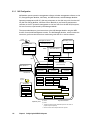
Logical Units (Without the FC interface board addition to the control unit) ... 99
Logical Units (With the FC interface board addition to the control unit) ....... 99
Logical Units (With the iSCSI interface board addition to the control unit) ... 100
Logical Units (NAS Model) .............................................................. 100
Fibre Channel Port-to-LUN Addressing (When the FC Interface Board is Not
Added) .................................................................................... 111
Fibre Channel Port-to-LUN Addressing (When the FC Interface Board is Added)112
iSCSI Port-to-LUN Addressing (When iSCSI interface board is installed)........ 113
Alternate Pathing (When the FC Interface board is not added) ................. 114
Alternate Pathing (When the FC Interface board is added) ...................... 115
Alternate Pathing (When the iSCSI Interface board is added) ................... 115
Fibre Channel Setting................................................................... 128
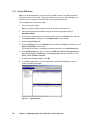
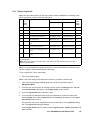
Logical Status Tab....................................................................... 138
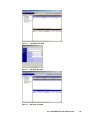
Logical Status Tab (NAS) ............................................................... 139
RAID Group Dialog Box.................................................................. 139
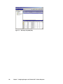
RAID Group is Updated ................................................................. 139
RAID Group is Updated (NAS) .......................................................... 140
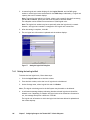
Setting the Logical Unit Dialog Box................................................... 144
LAN Connector Location................................................................ 218
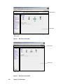
Main Screen Outline..................................................................... 219
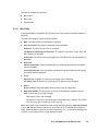
Main Screen Outline (NAS) ............................................................. 220
Main Screen Outline (iSCSI) ............................................................ 220
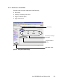
Subsystem Condition Display .......................................................... 223
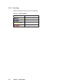
Patrol Lamp Display..................................................................... 224
Exchange Parts Status Display......................................................... 225
Component Status Screen.............................................................. 226
Component Status Screen (Controller/Battery/Cache/Loop/Host Computer) 227
Component Status Screen (AC/ENC/FAN) ........................................... 227
NNC Information Screen................................................................ 228
Warning Information Screen ........................................................... 233
Information Message Screen ........................................................... 234
Buzzer Volume Screen .................................................................. 235
Subsystem Status Screen ............................................................... 239
Progress Condition Display ............................................................. 240
Replace Part Summary Screen (HDD) ................................................ 241
NNC Information Screen................................................................ 242
Message Analysis......................................................................... 253
Acer | HDS AMS200 User and Reference Guide
xvii
xviii
Contents
List of Tables
Table 2.1
Table 2.2
Table 2.3
Table 2.4
Table 2.5
Table 2.6
Table 2.7
Table 2.8
Table 2.9
Table 2.10
Table 2.11
Table 2.12
Table 2.13
Table 2.14
Table 2.15
Table 2.16
Table 4.1
Table 4.2
Table 4.3
Table 4.4
Table 4.5
Table 4.6
Table 4.7
Table 4.8
Table 4.9
Table 4.10
Table 4.11
Table 4.12
Table 4.13
Table 4.14
Table 4.15
Table 4.16
Table 4.17
Table 4.18
Table 4.19
Table 4.20
Table 4.21
Table 4.22
Table 4.23
Table 4.24
Table 5.1
Table 5.2
Table 5.3
Table 5.4
Table 7.1
Table 7.2
Table 7.3
Table 7.4
Caution Statements ...................................................................... 20
Symbols Contained in Warning Labels................................................. 20
AMS200 Dimensions and Weight of Rack-Mount Model ............................. 26
AMS200 Dimensions and Weight of Floor Model ..................................... 26
AMS200 Dimensions and Weight of the NAS Unit .................................... 27
Internal Logic Specification of AMS200 Rack-Mount Model ........................ 30
Principal Functions of AMS200 Cables................................................. 30
Environmental Specifications........................................................... 32
Input Power and Insulation Performance Specifications for Rack-Mount Model 32
Input Power and Insulation Performance Specifications for the Floor Model... 33
Input Power and Insulation Performance Specifications for the NAS Unit ...... 33
Vibration and Shock Tolerances........................................................ 34
Reliability of AMS200 Rack-Mount Model (RKS/RKAJ) .............................. 35
Reliability of AMS200 Rack-Mount Model (RKS/RKAJAT) ........................... 36
Reliability of AMS200 Floor Model ..................................................... 37
Reliability of AMS200 Floor Model ..................................................... 38
Available Host Connectors of Each Topology Setting and Connection /Method 60
Available Fibre Channel Connection Configuration ................................. 61
Basic Specifications of Rack-Mount Model............................................ 66
Basic Specifications of the Floor Model............................................... 68
RKS, RKA, and RKA/RKAJAT Front Bezel Component Functions .................. 71
RKNAS Front Bezel Component Functions ............................................ 72
Panel Assembly Switch Functions ...................................................... 75
Backup Battery Unit Switch Functions ................................................ 76
Power Unit Switch Functions ........................................................... 76
RKNAS Switch Functions ................................................................. 77
Power Unit Connector Functions....................................................... 78
Power Unit Connector Functions....................................................... 79
Control Unit Connector Functions ..................................................... 80
RKNAS Connector Functions ............................................................ 81
Disk Drive Display LED Functions....................................................... 83
Disk Drive Display (RKAJ, RKAJAT) LED Functions................................... 84
Battery Backup Unit LED Functions.................................................... 84
ENC Unit LED Functions ................................................................. 85
SENC Unit LED Functions ................................................................ 86
Power Unit LED Functions............................................................... 87
Fan Assembly LED Functions............................................................ 87
Control Unit LED Functions ............................................................. 88
RKNAS LED Functions (front) ........................................................... 90
RKNAS LED Functions (rear) ............................................................ 91
Rack-Mount and Floor Model RAID Specifications ................................... 97
Floor Model RAID Specifications........................................................ 97
Rack-Mount Model Cache Specifications.............................................. 98
Floor Model Cache Specifications...................................................... 98
Storage for Parameters................................................................. 126
Formatting Message ..................................................................... 149
Simple Setting Item List ................................................................ 182
Additional Parameter Setting Items .................................................. 183
Acer | HDS AMS200 User and Reference Guide
xix
Table 7.5
Table 8.1
Table 8.2
Table 8.3
Table 8.4
Table 8.5
Table 8.6
Table 8.7
Table 8.8
Table 8.9
Table 8.10
xx
Contents
Capacity Restriction of System LU.................................................... 193
Web Operational Environment ........................................................ 214
AMS200 WEB Function Supported Browser/Version ................................ 215
Network Parameters .................................................................... 217
Message Code Types .................................................................... 245
Flash Detected Messages ............................................................... 246
Progress Messages (continues on next page)........................................ 247
Warning Messages ....................................................................... 250
Failure Messages......................................................................... 250
How to Read Failure Information (continues to the next page) ................. 251
Collection Mode ......................................................................... 259
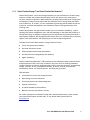
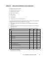
Chapter 1
Overview of the AMS200 Subsystem
This chapter includes the following:
Overview Features (see section 1.1)
Rack-Mount Model (see section 1.2)
Floor Model (see section 1.3)
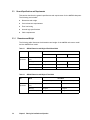
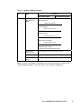
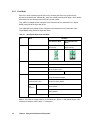
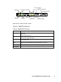
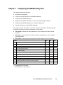
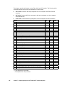
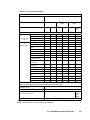
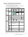
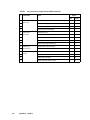
This chapter provides information on the Fibre, NAS, and iSCSI models. The following table
illustrates sections that provide an explanation for each model.
Fibre model: Connects disk array subsystem to a host computer with Fibre Channel
interface.
NAS model: Connects NAS Unit connected to disk array subsystem to a host computer
with LAN interface.
iSCSI model: Connects disk array subsystem to a host computer with iSCSI interface.
Sections
Fibre
NAS
iSCSI
Overview Features
{
{
{
1.1.1 High Data Availability
{
{
{
1.1.2 Connectivity
{
{
{
1.1.3 Scalability
{
{
{
1.1.4 Performance Reporting and Monitoring
{
{
{
1.1.5 Reliability, Availability, and Serviceability
{
{
{
1.1.6 Hitachi Freedom Storage™ and Hitachi Freedom Data Networks™
{
{
{
1.2
Rack-Mount Model
{
{
{
1.3
Floor Model
{
−
{
1.1
{: An explanation is provided.
—: An explanation is not provided.
Acer | HDS AMS200 User and Reference Guide
1
1.1
Overview Features
The Acer | HDS Adaptable Modular Storage AMS200 subsystem (hereafter referred to as the
AMS200) is available in two models: the floor model and the rack-mount model.
There are two types of the AMS200 floor model. The first type is a combination of the
DF700-RKS (hereafter referred to as the RKS) and the floor standing kit DF-F700-H1J
(hereafter referred to as the Floor [RKS+H1J] Model). The second type is a combination of
the RKS, the DF700-RKAJ (hereafter referred to as RKAJ), and the floor standing kit DF-F700H2J (hereafter referred to as the Floor [RKS+RKAJ+H2J] Model).
The AMS200 rack-mount model is a subsystem that combines the RKS, RKAJ/RKAJAT, and the
DF-700-RKNAS2G (hereafter referred to as RKNAS). For information regarding model types,
see sections 1.2 and 1.3.
The following AMS200 subsystem features are discussed in this section:
1.1.1
High Data Availability
Connectivity
Scalability
Performance Reporting and Monitoring
Reliability, Availability, and Serviceability
Hitachi Freedom Storage™ and Hitachi Freedom Data Networks™
High Data Availability
The AMS200 is designed for high performance and protection of user data. See section 1.2
for additional information on the reliability and availability features of the Acer | HDS
AMS200 subsystem.
1.1.2
Connectivity
The Acer | HDS AMS200 subsystem provides connectivity to most open systems through a
standard Fibre Channel interface or Network interfaces. The following describes the features
of Fibre Channel and Ethernet.
High-Speed Data Transfer
Fibre Channel: When using the Fibre Channel for the host interface, the AMS200 subsystem
can transfer data between the host computer and the subsystem at a maximum speed of 200
MB/sec. (400 M bytes/s when the optional interface is connected). Throughput can be
accessed by connecting multiple devices through the Fibre Channel Switch even when
accessing multiple hosts.
2
Chapter 1
Overview of the AMS200 Subsystem
Ethernet: With the 1 G bps Ethernet connection, the subsystem can transfer data between
host computer and the subsystem at a maximum speed of 100 M bytes/s per port via a
network. Enough throughput can be obtained even when having multiple access to the
multiple devices connected to the same network loop.
Cable
Fibre Channel: With Fibre Channel, the subsystem can be located up to 300 meters from the
host.
Ethernet: With Ethernet, the subsystem can be located up to 100 meters from the host. The
subsystem can be installed in the location far from the host.
The Number of Connectable Devices
Fibre Channel: The AMS200 subsystem enables you to construct a system which can connect
up to 126 fibre channel devices by using the fibre channel interface and connecting the FCAL and the FC-SW.
Security Function
Fibre Channel and Ethernet: When the system is configured to connect multiple hosts, a
function is provided which rejects a boot by any host except a specified host. This function
can prevent access from an illegal host.
1.1.3
Scalability
The architecture of the AMS200 enables the user to scale the subsystem to meet a wide
range of capacity and performance requirements:
1.1.4
You can construct a variety of systems; for example, a system with 15 disk drives can be
configured using a single RKS, or a more complex system can be set up using the
maximum of 105 disk drives, expanded by connecting up to 6 RKAJs/RKAJATs to the RKS.
Up to 15 spare disks can be set up in any location. Use the system effectively by
configuring each spare disk in a disk drive slot left unused due to system construction.
From the host computer, the subsystem can be used as a single large-scale disk drive or
as 512 logical disks (LUs) maximum.
Performance Reporting and Monitoring
The Storage Navigator-Modular program provides the capability to either monitor the disk
array in real-time or to collect historical data regarding the performance of the disk array.
Acer | HDS AMS200 User and Reference Guide
3
1.1.5
Reliability, Availability, and Serviceability
The AMS200 subsystem is not expected to fail in any way that would interrupt user access to
data. The AMS200 can sustain single component failures and still continue to provide full
access to all stored user data.
Note: While access to user data will not normally be compromised, the failure of any single
key component may degrade performance.
The reliability, availability, and serviceability features of the AMS200 subsystem include:
High-Availability capability. The AMS200 subsystem provides high-availability capability
for all critical components. The AMS200 uses component and function redundancy to
provide high availability for many subsystem components.
The Controller of the AMS200 subsystem increases data reliability by adding original 8byte data assurance codes to data from a host computer by automatically generating
them, writing them in the disk drive together with the data, and checking them when
reading the data. On the data bus in the controller, the automatic generation of the
data assurance codes and the check are executed to enhance data reliability in data
distribution/concentration control, particular to that disk array.
This function monitors potential disk failure. Before failure occurs, the data copy
operation can be automatically performed in the background. The dynamic sparing
feature enables the subsystem to replace the spare disk due to redundancy (excluding
RAID0 configuration) and provides high reliability.
4
Redundant power supply systems. Each AMS200 unit has a set of two power supplies.
Each power supply can provide power for the entire subsystem in the unlikely event of
power supply failure. The power supplies of each set can be connected across power
boundaries so that each set can continue to provide power if a power outage occurs.
Each unit of the AMS200 can sustain the loss of a single power supply and still continue
operation.
High capacity cache. The AMS200 subsystem supports 2 GBs high capacity cache per
controller. Writing completion can be reported to the host system when data is written
to cache.
Chapter 1
Overview of the AMS200 Subsystem
1.1.6
Hitachi Freedom Storage™ and Hitachi Freedom Data Networks™
Hitachi Data Systems’ end-to-end Storage Solutions give you the freedom to locate storage
wherever it makes the greatest business sense to do so and protect your investment in
currently installed components. Made possible by the advent and proliferation of high-speed
technologies, storage area networks break the traditional server/storage bond and enable
total connectivity. As a result, you can consolidate large storage pools shareable across the
enterprise, centralize management, and dramatically improve storage utilization while
reducing costs.
Hitachi Data Systems’ Storage Solutions enable you to increase data availability, counter
spiraling information management costs, and take advantage of the speed and flexibility of
Storage technology. In addition to supporting the Storage Networking Industry Association’s
open-systems standards, HDS Storage Solutions reduce total cost of ownership by minimizing
support costs and downtime, and optimizing server and storage configurations.
The benefits of Hitachi Data Systems’ Storage Solutions include:
Server/storage system scalability.
Improved information access.
Enhanced application/backup performance.
Increased resource manageability and reliability.
Higher availability.
Hitachi Freedom Data Networks™ (FDN) responds to the challenge of open architecture and
multiple platforms. FDN is the locus of Hitachi’s long-term vision for offering businesses
complete freedom of choice in establishing data-centric enterprise networks, encompassing
storage, switches, servers, management software, protocols, services, and networks
developed by Hitachi, our alliance partners, and third party providers.
FDN facilitates:
Consolidation of server and storage resources.
Data sharing across the enterprise.
Centralized resource and data management.
Superior data security.
Increased availability and scalability.
Business continuity and disaster recovery.
For further information on Freedom Storage and Freedom Data Networks, please contact
your Hitachi Data Systems account team, or visit Hitachi Data Systems online at
www.hds.com.
Acer | HDS AMS200 User and Reference Guide
5
1.2
Rack-Mount Model
The rack-mount model is composed of a single RKS or a combination of the RKS,
RKAJ/RKAJAT, and RKNAS mounted on a rack frame. The RKS is capable of mounting up to
15 disk drives; a controller to perform RAID control on the drives is included. The
RKAJ/RKAJAT is capable of mounting up to 15 disk drives and controls the drives through a
connection with an RKS. The RKAJ/RKAJAT is provided with no controller.
6
Chapter 1
Overview of the AMS200 Subsystem
1.3
Floor Model
There are two floor model styles:
Floor (RKS+H1J) Model.
Floor (RKS+RKAJ+H2J) Model.
The Floor (RKS+H1J) Model is capable of mounting up to 15 disk drives and include a
controller to perform RAID control on the drives. The Floor (RKS+RKAJ+H2J) model is capable
of mounting up to 30 disk drives and includes a controller to perform RAID control on the
drives.
Note: For the specifications of the Floor model, refer to Chapter 2.
Acer | HDS AMS200 User and Reference Guide
7
8
Chapter 1
Overview of the AMS200 Subsystem
Chapter 2
Planning for Installation and Operation
This chapter provides information for planning and preparing a site before and during
installation of the Acer | HDS AMS200 subsystem. Please read this chapter carefully before
beginning your installation planning.
Note: The general information in this chapter is provided to assist in installation planning
and is not intended to be complete. The internal AMS200 installation and maintenance
documents used by Acer | HDS personnel contain complete specifications. The exact
electrical power interfaces and requirements for each site must be determined and verified
to meet the applicable local regulations. For further information on site preparation for
AMS200 installations, contact your Acer | HDS account team or the Acer | HDS Support
Center.
This chapter includes the following:
User Responsibilities
Safety Precautions
Dimensions and Weight
Service Clearance Requirements
Floor Load Rating
Cable Requirements
Environmental Specifications
Acer | HDS AMS200 User and Reference Guide
9
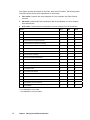
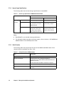
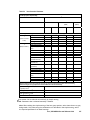
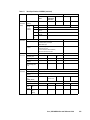
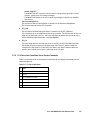
This chapter provides information on the Fibre, NAS, and iSCSI models. The following table
illustrates sections that provide explanations for each model.
Fibre model: Connects disk array subsystem to a host computer with Fibre Channel
interface.
NAS model: Connects NAS Unit connected to disk array subsystem to a host computer
with LAN interface.
iSCSI model: Connects disk array subsystem to a host computer with iSCSI interface.
Sections
NAS
iSCSI
2.1
User Responsibilities
{
{
{
2.2
2.2.1 Symbol Marks
{
{
{
2.2.2 Repair, Modification, and Diasasembly
{
{
{
2.2.3 Precautions for Using the Equipment
{
{
{
2.2.4 Precautions for Inspection and Cleaning
{
{
{
2.2.5 Emergency Precautions
{
{
{
2.2.6 Warning Notices
{
{
{
2.2.7 Locations of Warning Labels on the Equipment
{
{
{
2.3.1 Dimensions and Weight
{
{
{
2.3.2 Service Clearance Requirements
{
{
{
2.3.3 1 Floor Load Rating for the AMS200 Rack-Mount Model
{
{
{
2.3.3 1 Floor Load Rating for the AMS200 Floor Model
{
−
{
2.3.4 Internal Logic Specifications
{
{
{
2.3.5 Cable Function
{
{
{
2.4.1 Environmental Hazards
{
{
{
2.4.2 Temperature and Humidity Requirements
{
{
{
2.4.3 Input Power and Insulation Performance Specifications
{
{
{
2.4.4 Air Flow Requirements
{
{
{
2.4.5 Vibration and Shock Tolerances
{
{
{
2.4.6 Reliability
{
{
{
2.3
2.4
{: An explanation is provided.
—: An explanation is not provided.
10
Fibre
Chapter 2 Planning for Installation and Operation
2.1
User Responsibilities
Before the AMS200 subsystem arrives for installation, you must provide the following items
to ensure proper installation and configuration:
Physical space necessary for proper subsystem function and maintenance activity
Electrical input power
Connectors and receptacles
Air conditioning
Floor ventilation areas (recommended but not required)
Cable access holes
Acer | HDS AMS200 User and Reference Guide
11
2.2
Safety Precautions
When using the AMS200 disk array subsystem, follow these cautionary procedures:
Perform operations in accordance with the instructions or procedures described in this
manual.
Follow the cautionary notes written on labels affixed to the equipment.
Follow the cautionary notes written in this manual.
This disk array is a class 1 laser system which does not emit a hazardous laser beam.
Operate this subsystem using the instructions included in this guide; do not perform
operations that are not specified. Otherwise, unexpected failures or accidents may
result.
It is impossible to describe every hazard that may exist with this equipment. Please be
aware of hazards not described in this manual. Work safely.
The following information is included in this section:
12
Symbol marks
Repair, modification, and disassembly
Precautions for using the equipment
Precautions for inspection and cleaning
Emergency precautions
Warning notices
Chapter 2 Planning for Installation and Operation
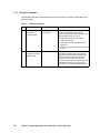
2.2.1
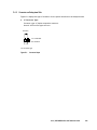
Symbol Marks
The warning labels which appear on the subsystem and/or in this guide indicate potential
safety hazards. When you see these symbols, observe the safety instructions that follow:
This is the safety alert symbol. It is used to alert you to
potential personal injury hazards. Obey all safety messages
that follow this symbol to avoid possible injury or death.
DANGER
Indicates an imminently hazardous situation which, if not
avoided, will result in death or serious injury.
WARNING
Indicates a potentially hazardous situation which, if not
avoided, could result in death or serious injury.
CAUTION
Indicates a potentially hazardous situation which, if not
avoided, may result in minor or moderate injury.
CAUTION
2.2.2
Indicates a potentially hazardous situation which, if not
avoided, may result in property damage.
Repair, Modification, and Disassembly
Users must not repair, remodel, or disassemble the equipment. Such actions may cause
hazardous conditions for the user and/or the equipment.
Acer | HDS AMS200 User and Reference Guide
13
2.2.3
Precautions for Using Equipment
Use special precautions for the following:
2.2.3.1
2.2.3.2
2.2.3.3
14
Equipment
Cables
Air vents
Battery unit
Nickel-Hydride rechargeable battery instructions
Miscellaneous and other
Equipment
If you notice unusual heat generation, odors, or smoke emission, shut off the power feed
to the equipment and contact the Customer Engineer. Leaving such conditions
unattended may result in hazardous physical conditions and equipment failure.
Avoid physical disruption to the equipment. This may result in hazardous physical
conditions and equipment failure.
Do not place heavy objects on top of the disk array. Avoid using the equipment for any
use other than its original purpose; otherwise, an injury or equipment failure may result.
Cables
Avoid obstructing walkways when routing cables.
Do not allow heavy material to be placed on cables. Do not place cables near any
apparatus that generates heat. Do not step on or subject cables or connectors to
shearing or pulling forces; the cable jacket can be damaged and can break, resulting in
an electric shock, fire, or loss of data.
Make sure that electrical and signal cables are clean before connecting them. Any dirt
on a connector should be removed before inserting the connector into a socket.
Air Vents
Make certain that the air vents are free of obstruction. They should be inspected
periodically.
Do not place metallic material such as paper clips or any combustible material such as
paper into or near the air vents. This may result in electric shock or fire.
Chapter 2 Planning for Installation and Operation
2.2.3.4
Battery Unit
Observe the following when handling the battery:
Do not disassemble or tamper with the battery.
Do not allow the battery to be physically damaged. If the battery is physically damaged,
have it replaced as soon as possible.
Do not connect the two terminals of the battery directly to each other; this will create a
short circuit.
Do not tamper with cable insulation.
Do not connect the battery to any equipment other than the AMS200 subsystem.
Do not expose the battery to high temperatures.
Use only the specified battery.
Acer | HDS AMS200 User and Reference Guide
15
2.2.3.5
Nickel-Hydride Rechargeable Battery Instructions
These instructions explain what you must observe when you use a nickel-hydride
rechargeable battery (hereafter it is referred to as the battery). If you use the battery
incorrectly, it can overheat ignite, burst or explode, damaging and deteriorating its
performance/life. Read and follow the instructions below:
Danger
1. Do not disassemble the case; do not modify it or peel off the label. There are high
voltage parts inside: if you attempt any of these actions, this can result in electrical
shock or burning.
2. Do not disassemble the battery; this can cause short circuits inside or outside of the
battery. If the components are exposed to the air, the battery can overheat, burst or
ignite. Disassembling the battery can expose you to alkaline solution, which can be
dangerous.
3. Do not cut the output cable. Do not modify the connector. If you attempt any of these
actions, an electrical shock or burn can result. A short-circuit may cause abnormal
chemical reactions inside the battery which leads to overheating, bursting or ignition.
4. Follow the instructions when you recharge the battery pack. If you recharge it in a way
different from specified here, it may cause the following problems: The battery may
become charged excessively; excessive current may be produced; or the battery cannot
be recharged. As a result, the battery may leak, become overheated, burst, or ignite.
5. Do not use excessive force when you connect the battery pack to the charger or other
devices. If you cannot connect it easily, check that the positive and negative positions
are correct for the connector. If you connect the battery in reverse, it will be charged
incorrectly and abnormal chemical reactions may occur inside. As a result, the battery
may become overheated, burst or ignite.
6. Do not connect the battery to a power receptacle. If you apply an excessive amount of
voltage to the battery, it may produce excessive current making the battery overheat,
burst or ignite.
7. Do not use or leave the battery where the temperature can become high, such as, near a
fire or a heating element. High temperatures can damage the battery's separator, which
may cause short circuit, making it overheat, burst or ignite.
8. Do not incinerate or heat the battery pack. If you do so, the insulator may melt, the
safety fuse/mechanism may be damaged, or the electrolyte may gush out. As a result,
the battery can burst, explode or ignite.
9. Do not connect the negative terminal to the positive with metal wire. Do not carry or
store the battery with other metal parts. This can cause a short circuit or produce an
excessive current which can cause the battery to leak, overheat, burst or ignite.
10. Do not let the battery become wet by soaking it in the water or seawater. If the battery
becomes wet, a short circuit can occur and an excessive amount of current can be
produced, causing abnormal chemical reactions inside. As a result, the battery may
become overheated, burst or ignite.
16
Chapter 2 Planning for Installation and Operation
11. Do not nail or hammer the battery. The battery may be broken or dented and a short
circuit may occur inside. As a result, the battery may become overheated, burst or
ignite.
12. Do not solder directly to the battery. If you do so, heat will melt the insulator and
damage the safety fuse/mechanism. As a result, the battery may leak or may become
overheated, burst or ignite.
Warning
1. If you find anything strange or unusual with the battery when you use/carry/store it,
remove the battery from the device and stop using it. For example, strange smells,
strange colors, or deformation are a sign you must stop using the battery.
2. If it takes longer than the specified time to complete recharging, stop recharging the
battery; otherwise, the battery may become overheated, burst or ignite.
If the battery leaks and gets into your eyes, immediately flush your eyes with clean water
(tap water) and do not rub your eye. Visit the doctor immediately. If you do not seek any
treatment for your eyes, problems may occur later. Because the battery uses highly
concentrated alkaline as electrolyte, it can burn; you may lose your sight if it makes contact
with your eyes. If the battery's liquid contacts your skin or eyes, you must flush them with
plenty of clean water and visit a doctor at once.
2.2.3.6
Miscellaneous and Other
When a failure occurs in the unit, take action according to the procedures recommended in
this manual. If the difficulty does not correspond to the corrective measures documented in
this manual, contact the Customer Engineer.
Acer | HDS AMS200 User and Reference Guide
17
2.2.4
18
Inspection and Cleaning Precautions
If a maintenance activity requires that the unit be powered off, make sure that the
power-off sequence described in the manual is performed before proceeding with
maintenance.
Do not work on the unit in a damp or flooded environment.
Do not obstruct access to the unit with parts or tools.
When performing the work with the door open, take off metal watches or jewelry to
prevent electric shock. If you wear metal-frame glasses, do not touch the equipment.
Ensure that loose clothing, jewelry, or hair do not become tangled in moving
components.
There are high-voltage parts in the equipment. Observe the cautionary statements in the
manual to make sure that high-voltage components are not touched during maintenance.
Another person should be on alert to shut off the power feed to the equipment.
After the power feed to the equipment is shut off, electricity remains in the equipment
for a period of time. Therefore, do not touch any components other than those indicated
in this manual.
The equipment can become extremely hot. Do not touch any part other than those
indicated in this manual.
When working with the door open, wear cotton gloves to prevent your hands from
touching sharp objects.
Chapter 2 Planning for Installation and Operation
2.2.5
Emergency Precautions
Follow these emergency precautions for the following:
2.2.5.1
2.2.5.2
Electric Shock
Fire
Electric Shock
Do NOT immediately touch the person struck by electricity. You could be the second
victim.
To shut off the electric flow to a victim, disconnect the power feed cable of the
equipment. In spite of this action, electricity may not be shut off. Separate the victim
from the current source by using a non-conductive material such as dry wooden bar.
Call an ambulance.
When the victim has lost consciousness, practice artificial respiration on the victim. To
prepare for such a case, learn how to practice artificial respiration.
When the victim’s heart has stopped, give a heart massage. This treatment should only
be conducted by a person who has been trained and qualified.
Fire
To shut off the electric flow to the equipment, pull out the power feed cable. This will
terminate the power supply.
If a fire cannot be extinguished when the electric flow has been shut off, use firefighting procedures and contact the fire department.
Acer | HDS AMS200 User and Reference Guide
19
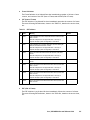
2.2.6
2.2.6.1
Warning Notices
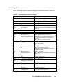
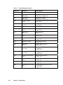
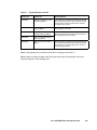
Caution Statements
Caution statements described in this manual and the pages where they appear are listed
below. Caution statements are indicated by the caution symbol:
Table 2.1
2.2.7
Caution Statements
Warning Statement
Corresponding Page
Cooling fans rotate at a high speed. Keep body parts and loose clothing away
from the cooling fans.
18
When cleaning, take care not to touch electrically charged parts. Electric shock
may result.
18, 19
Do not touch electrically charged components during parts replacement. Electric
shock may result.
19
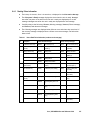
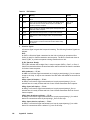
Warning Label Locations
Warning labels are pasted on sections of equipment which require special care. Read the
messages and observe the warning procedures. They are shown in the following figures:
Floor Model RKS+H1J
Floor Model RKS+RKAJ+H2J
Rack-Mount Model RKS
Rack-Mount Model RKAJ/RKAJAT
Table 2.2 lists and describes the symbols contained in warning labels.
Table 2.2
Symbol Mark
Symbols Contained in Warning Labels
Description
Caution-electric shock.
Caution-very hot.
20
Chapter 2 Planning for Installation and Operation
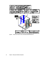
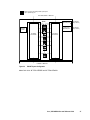
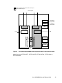
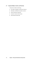
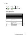
Figure 2.1
Positions and Contents of Labels on Floor Model RKS+H1HJ
Acer | HDS AMS200 User and Reference Guide
21
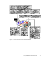
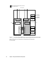
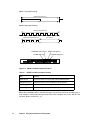
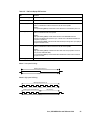
Figure 2.2
22
Positions and Contents of Labels on Rack-Mount Model RKS+RKAJ+H2J
Chapter 2 Planning for Installation and Operation
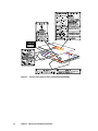
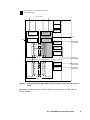
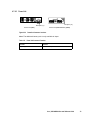
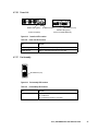
Figure 2.3
Positions and Contents of Labels on Rack-Mount Model RKS
Acer | HDS AMS200 User and Reference Guide
23
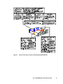
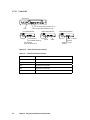
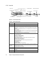
Figure 2.4
24
Positions and Contents of Labels on Rack-Mount Model RKNAS
Chapter 2 Planning for Installation and Operation
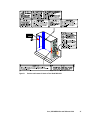
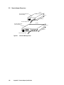
Figure 2.5
Positions and Contents of Labels on Rack-Mount Model RKAJ/RKAJAT
Acer | HDS AMS200 User and Reference Guide
25
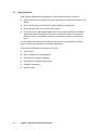
2.3
General Specifications and Requirements
This section describes the general specifications and requirements for the AMS200 subsystem.
The following are included:
2.3.1
Dimensions and weight
Service clearance requirements
Floor load rating
Internal logic specifications
Cable requirements
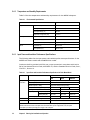
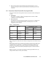
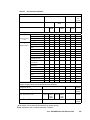
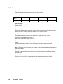
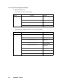
Dimensions and Weight
The following table illustrates the dimensions and weight of the AMS200 rack-mount model
and the AMS200 floor model.
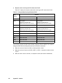
Table 2.3
Item
Physical
Specifications
Table 2.4
Item
Physical
Specifications
26
AMS200 Dimensions and Weight of Rack-Mount Model
Model
Rack-mount Model
RKS
RKAJ
RKAJAT
Chassis size (W×D×H)
(mm)
483×650×174
483×650×129
Mass (kg)
56 approx
40 approx
Acoustic noise (dB)
57 approx
60 approx
Required height (EIA unit)
4
3
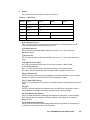
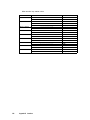
AMS200 Dimensions and Weight of Floor Model
Model
Floor Model
Floor (RKS+H1J) Model
Floor (RKS+RKAJ+H2J) Model
Chassis size (W×D×H)
(mm)
260×737×540
260×737×540
Mass (kg)
70 approx
115 approx
Acoustic noise (dB)
56 approx
59 approx
Chapter 2 Planning for Installation and Operation
Table 2.5
AMS200 Dimensions and Weight of the NAS Unit
Item
Physical
Specifications
Model
RKNAS
Chassis size (W×D×H)
(mm)
483×650×43
Mass (kg)
15 approx
Acoustic noise (dB)
60 approx
Acer | HDS AMS200 User and Reference Guide
27
2.3.2
Service Clearance Requirements
The following figure shows the floor area required for installing the equipment. Install the
equipment in a place with the area shown in the figure to avoid problems such as inadequate
service clearance or insufficient ventilation. All distances in the following figure are stated
in millimeters (mm).
Legend
: Area required for maintenance of the equipment
: Outside line of the equipment
: Area for opening/closing the door
: Leveling bolt position
: Caster position
: Front side of the equipment
305.9
255.8
18
219.8
18
18
420
269.9
18
420
75
75
30
622.5
562.5
30
75
472.5
622.5
562.5
30
30
18
18
59.7
300
59.7
136.4
Floor (RKS+H1J) Model
28
472.5
75
75
300
75
Chapter 2 Planning for Installation and Operation
18
18
59.2
59.2
187.5
Floor (RKS+RKAJ+H2J) Model
2.3.3
Floor Load Rating
This section includes:
2.3.3.1
Floor load rating for the AMS200 rack-mount model
Floor load rating for the AMS200 floor model
Floor Load Rating for AMS200 Rack-Mount Model
In the maximum configuration, the rack-mount model can be configured with 1 RKS and 6
additional units (RKAJs/RKAJATs and RKNAS). The total weight of the subsystem in this
configuration is 530 kg.
Note: For information about the global rack-mount model, refer to the Acer | HDS Global
19-Inch Rack Reference Guide (MK-93DF665).
2.3.3.2
Floor Load Rating for AMS200 Floor Model
The Floor (RKS+H1J) Model contains up to 2 controller boards and up to 15 disk drives. The
maximum configuration weighs 70 kg. To ensure adequate load-bearing capacity, plan for
the maximum configuration.
The Floor (RKS+RKAJ+H2J) Model contains up to 2 controller boards and up to 30 disk drives.
The maximum configuration weights 115kg. To ensure adequate load-bearing capacity, plan
for the maximum configuration.
Acer | HDS AMS200 User and Reference Guide
29
2.3.4
Internal Logic Specifications
The following table lists the internal logic specifications of the AMS200.
Table 2.6
Internal Logic Specification of AMS200 Rack-Mount Model
Item
Specification
RKS
RKNAS
Internal logic
Control CPU
Power PC7447A (500 MHz)
Intel LV-Xeon 2.8GHz
specification
Control memory
Flash memory: 2 M bytes
Bios: 1 M bytes
L2 cache memory: 512 k bytes
L2 cache memory: 1M bytes
SRAM: 64 M bytes
Data assurance method
Data bus: Through-parity
Data bus: Through-parity
Cache memory: ECC (1 bit for
correction, 2 bits for detection)
Cache memory: ECC (1 bit for
correction, 2 bits for detection)
Disk drive: Data assurance code
Notes:
2.3.5
RKAJ/RKAJAT is not included in these specifications.
For information about the global rack-mount model, refer to the Acer | HDS AMS200 and
WMS100 Global 19-Inch Rack Reference Guide.
Cable Function
The following table lists the principal functions of the AMS200 and RKNAS cables. Fibre
channel cables are available from Acer | HDS.
Table 2.7
Principal Functions of AMS200 Cables
Cable
Principal Use
Fibre Channel cable
Connect with a host or HBA/Switch.
LAN cable (Cross/Straight)
Connect the PCs for user, monitoring and maintenance.
Connect with a host or a HAB for Ethernet. (When iSCSI interface and
RKNAS are connected)
Connect between RKS and RKNAS for maintenance management.
30
ENC (ENCLOSURE) cable
Connect between the subsystems with Fibre Channel (FC_AL).
NAS interface cable
Connect between RKS and RKNAS for NAS control. (When RKNAS is
connected)
Chapter 2 Planning for Installation and Operation
2.4
Environmental Specifications and Requirements
To maintain optimal AMS200 performance, the AMS200 subsystem must be installed in a
proper environment. This section discusses the following necessary environmental
specifications and requirements:
2.4.1
Environmental hazards
Temperature and humidity requirements
Input power and insulation performance specifications
Air flow requirements
Vibration and shock tolerances
Reliability
Environmental Hazards
Do not install the subsystem in the places described below; the life of equipment
functioning will be shortened and equipment failures will occur. Avoid the following:
Direct sunlight exposure
Temperature and humidity variation (for example, near an air conditioner)
Close proximity to a device that generates electrical noise and motion (for example, air
conditioner that is not grounded and washing machine motor)
Close proximity to an apparatus that generates a strong magnetic field
Excessive dust
Frequent vibrations
An inclined floor
Note: Do not store or install the equipment in a high temperature environment of 40 degrees
centigrade or more; battery life will be shortened.
Acer | HDS AMS200 User and Reference Guide
31
2.4.2
Temperature and Humidity Requirements
Table 2.8 lists the temperature and humidity requirements for the AMS200 subsystem.
Table 2.8
Environmental Specifications
Item
Specification
Temperature
Humidity
Altitude
2.4.3
In operation (°C)
10 to 40
In non-operation (°C)
-10 to 50
In transport/storage (°C)
-30 to 60
Temperature change rate (°C/h)
10 or less
In operation (%)
8 to 80
In non-operation (%)
8 to 90
Maximum wet bulb temperature (°C)
29 (non-condensing)
In operation (m)
-300 to 3,000
In non-operation (m)
-300 to 12,000
Input Power and Insulation Performance Specifications
The following tables list the input power and insulation performance specifications for the
AMS200 rack-mount models and the AMS200 floor model.
Conductors shall be provided with 30 A over current protection in accordance with Article
240 of the National Electrical Code, ANSI/NFPA 70, and the Canadian Electrical Code, Part 1,
CSA C22.1, Section 14.
Table 2.9
Item
Input Power and Insulation Performance Specifications for Rack-Mount Model
Model
Rack-Mount Model
RKS
Input power
specification
RKAJ
Input voltage (V)
AC 100/200 (100-120/200-240)
Frequency (Hz)
50/60 ± 1
Number of phases, cabling
Single-phase with protective grounding
Steady-state current (A) (Note1) (Note2)
4.0×2/2.0×2
2.6×2/1.3×2
Breaking current (A)
16.0
10.0
Required power
RKAJAT
2.4×2/1.2×2
Steady state (VA)
800 or less
520 or less
480 or less
Starting state (VA)
800 or less
560 or less
480 or less
Heat value (kJ/h)
2,880 or less
1,875 or less
1,730 or less
Insulation
Insulation withstand voltage
AC 1,500 V (10 mA, 1 min)
performance
Insulation resistance
DC 500 V, 10 M Ω or more
Note 1: Power current of Nx2 described above is required for operation by a single power supply unit.
Note 2: It indicates the current consumption in the usual state. When a power supply failure occurs, the power
consumption is provided by the single power supply for the subsystem.
32
Chapter 2 Planning for Installation and Operation
Table 2.10
Input Power and Insulation Performance Specifications for the Floor Model
Item
Model
Floor Model
Floor (RKS+H1J) Model
Floor (RKS+RKAJ+H2J) Model
Input voltage (V)
AC 100/200 (100-120/200-240)
Frequency (Hz)
50/60 ± 1
Number of phases,
cabling
Single-phase with protective grounding
Steady-state current (A)
(Note 1) (Note 2)
4.0×2/2.0×2
Breaking current (A)
16.0
Required
power
Steady state
(VA)
800 or less
1,320 or less
Starting
state (VA)
800 or less
1,360 or less
Heat value (kJ/h)
2,880 or less
4,755 or less
Insulation
Insulation withstand
voltage
AC 1,500 V (10 mA, 1 min)
performance
Insulation resistance
DC 500 V, 10 M Ω or more
Input power
specification
4.0×2+2.6×2/2.0×2+1.3×2
Note1: Power current of Nx2 described above is required for operation by a single power supply unit.
Note2: The current value in the operation by a single power supply unit is same as that in the operation by both power
supply units.
Table 2.11
Input Power and Insulation Performance Specifications for the NAS Unit
Item
Model
RKNAS
Input power
Input voltage (V)
AC 100/200 (100-120/200-240)
specification
Frequency (Hz)
50/60 ± 1
Number of phases, cabling
Single-phase with protective grounding
Steady-state current (A)
2.0/1.4
Breaking current (A)
10.0
Required
power
Steady state
(VA)
280 or less
Starting state
(VA)
280 or less
Heat value (kJ/h)
Insulation
performance
1,010 or less
Insulation withstand
voltage
AC 1,500 V (10 mA, 1 min)
Insulation resistance
DC 500 V, 10 M Ω or more
Acer | HDS AMS200 User and Reference Guide
33
2.4.4
Air Flow Requirements
The AMS200 subsystem is air-cooled. Air must enter the subsystem through the airflow
intakes at the front of each subsystem and must be exhausted out of the back.
2.4.5
Vibration and Shock Tolerances
Table 2.12 lists the vibration and shock tolerance data for the AMS200 subsystem. The
AMS200 can tolerate vibration and shock within these limits and continue to perform
normally. The user should consider these requirements if installing the AMS200 near large
generators located on the floor above or below the AMS200 subsystem. Generators or any
other source of vibration, if not insulated or shock-mounted, can cause excessive vibration
that may affect the subsystem.
Table 2.12
Vibration and Shock Tolerances
Item
Vibration
Impact
Specification
In operation (m/s2)
2.5 or less
In non-operation (m/s2)
5.0 or less
In transport (packed) (m/s2)
5.0 or less
In operation (m/s2)
20 or less
In non-operation (m/s2)
50 or less
In transport (packed) (m/s2)
80 or less
Angle at which the subsystem will turn over (º)
34
Chapter 2 Planning for Installation and Operation
15 or less
2.4.6
Reliability
The reliability of the AMS200 is described in the following tables.
The following reliability does not change even when the RKNAS is connected to the system.
Table 2.13
Item
Reliability of AMS200 Rack-Mount Model (RKS/RKAJ)
Model
Rack-Mount Model
RKS
Reliability
MTBDL (Mean
Time Between Data
Lost)
(Note)
RKAJ
About 20 million hour or longer (in RAID 5 configuration)
RAID 6 configuration
3
(MTBF of the disk drive)
2
n(n−1)(n−2)×Number of Parity group×MTTR
RAID 5 configuration:
2
(MTBF of the disk drive)
n(n−1)×Number of Parity group×MTTR
RAID 0 configuration
MTBF of the disk drive
n×Number of Parity group
RAID 1 or RAID1+0 configuration
2
(MTBF of the disk drive)
n×1×Number of Parity group×MTTR
MTTR: Mean Time To Repair
n: Number of the mounted disk drive/Parity group
Drop in package
(JIS Z 0200-1997)
No abnormality must be caused by a free drop of level IV.
Radio frequency
radiation
Instantaneous
power failure
10 ms (100% dip)
Note: The value of the MTBDL is calculated in the following configuration: RAID 5:68 sp
((15D+1P)(4group+4(spare)). This value varies on user's system configuration.
Acer | HDS AMS200 User and Reference Guide
35
Table 2.14
Item
Reliability of AMS200 Rack-Mount Model (RKS/RKAJAT)
Model
Rack-Mount Model
RKS
Reliability
MTBDL (Mean
Time Between Data
Lost)
(Note)
RKAJAT
About 20 million hour or longer (in RAID5 configuration)
RAID 6 configuration:
2
(MTBF of the disk drive)
n(n−1)×Number of Parity group×MTTR
RAID 1 or RAID1+0 configuration
2
(MTBF of the disk drive)
n×1×Number of Parity group×MTTR
MTTR: Mean Time To Repair
n: Number of the mounted disk drive/Parity group
Drop in package
(JIS Z 0200-1997)
No abnormality must be caused by a free drop of level IV.
Radio frequency
radiation
Conforms to FCC Class A
Instantaneous
power failure
10 ms (100% dip)
Note: The value of the MTBDL is calculated in the following configuration: RAID 5:68 sp
((15D+1P)(4group+4(spare)). This value varies on user's system configuration.
36
Chapter 2 Planning for Installation and Operation
Table 2.15
Item
Reliability of AMS200 Floor Model
Model
Floor Model
Floor (RKS+H1J) Model
Reliability
MTBDL (Mean Time
Between Data Lost)
(Note)
Floor (RKS+RKAJ+H2J) Model
About 5 million hour or longer (in RAID 5 configuration)
RAID 6 configuration:
3
(MTBF of the disk drive)
2
n(n−1)(n−2)×Number of Parity group×MTTR
RAID 5 configuration:
2
(MTBF of the disk drive)
n(n−1)×Number of Parity group×MTTR
RAID0 configuration
MTBF of the disk drive
n×Number of Parity group
RAID1, RAID1+0 configuration
2
(MTBF of the disk drive)
n×1×Number of Parity group×MTTR
MTTR: Mean Time To Repair
n: Number of the mounted disk drive/Parity group
Drop in package
(JIS Z 0200-1997)
No abnormality must be caused by a free drop of level IV.
Radio frequency radiation
Conforms to FCC Class A
Instantaneous power
failure
10 ms (100% dip)
Note: The value of the MTBDL is calculated in the following configuration: RAID 5:68 sp
((15D+1P)(4group+4(spare)). This value varies on user's system configuration.
Acer | HDS AMS200 User and Reference Guide
37
Table 2.16
Item
Reliability of AMS200 Floor Model
Model
Floor Model
Floor (RKS+H1J) Model
Reliability
MTBDL (Mean Time
Between Data Lost)
(Note)
Floor (RKS+RKAJ+H2J) Model
About 5 million hour or longer (in RAID 5 configuration)
RAID 6 configuration:
3
(MTBF of the disk drive)
2
n(n−1)(n−2)×Number of Parity group×MTTR
RAID 5 configuration:
2
(MTBF of the disk drive)
n(n−1)×Number of Parity group×MTTR
RAID0 configuration
MTBF of the disk drive
n×Number of Parity group
RAID1, RAID1+0 configuration
2
(MTBF of the disk drive)
n×1×Number of Parity group×MTTR
MTTR: Mean Time To Repair
n: Number of the mounted disk drive/Parity group
Drop in package
(JIS Z 0200-1997)
No abnormality must be caused by a free drop of level IV.
Radio frequency radiation
Conforms to FCC Class A
Instantaneous power
failure
10 ms (100% dip)
Note: The value of the MTBDL is calculated in the following configuration: RAID 5:68 sp
((15D+1P)(4group+4(spare)). This value varies on user's system configuration.
38
Chapter 2 Planning for Installation and Operation
Chapter 3
Powering On/Off Procedure
The disk drive may emit audible mechanical sounds when the disk drive is started (spun up),
immediately after the subsystem is powered on and powered off (spun down). However, this
does not indicate a problem if the WARNING or ALARM LED of the basic frame is off; you may
use the subsystem.
This section describes power on/off procedures for the following:
AMS200 Rack-Mount Model
AMS200 Floor Model
This chapter provides the information on the Fibre, NAS, and iSCSI models. The following
table illustrates the sections that provide the explanation for each model. According to the
customer 's model, please read the required section.
Fibre model: Connects disk array subsystem to a host computer with Fibre Channel
interface.
NAS model: Connects NAS Unit connected to disk array subsystem to a host computer
with LAN interface.
iSCSI model: Connects disk array subsystem to a host computer with iSCSI interface.
Sections
Fibre
NAS
iSCSI
3.1
3.1.1 Subsystem Power On
{
{
{
3.1.2 Subsystem Power Off
{
{
{
3.1.3 Stop/Start/Restart of the NAS OS
−
{
−
3.2.1 Subsystem Power On
{
−
{
3.2.2 Subsystem Power Off
{
−
{
3.2
{: The explanation is provided.
—: The explanation is not provided.
If the array subsystem connected to the NAS Unit is restarted, the cluster between the NAS
Units stops. When the array subsystem is unavoidably restarted, execute it after stopping
the cluster between the NAS Units and stopping the NAS OS of both NAS Units. Start the
cluster between the NAS Units again after completing the restart for the array subsystem.
Acer | HDS AMS200 User and Reference Guide
39
3.1
AMS200 Rack-Mount Model
The following steps describe power on/off procedures for the AMS200 rack-mount model.
Note: For information about the global rack-mount model, refer to the Acer | HDS AMS200
and WMS100 Global Global 19-Inch Rack Reference Guide.
3.1.1
Subsystem Power On
Note: The EALM lamp (red) of the controller (on the rear side of the subsystem) may come
on between subsystem power-on and Ready status. However, it is not a problem if the EALM
lamp (red) goes out during this period of time.
To power on the subsystem:
1. Verify that the main switch is turned off.
2. Verify that the AC power unit switch of each power unit is turned off.
3. Verify that the circuit breaker (CB1) is turned off.
4. When the RKNAS is mounted on the rack, verify that the AC Power Unit Switch of the
power unit on the RKNAS is turned off.
5. Turn on the circuit breaker (CB1) of the PDB.
6. Turn on the AC Power Unit Switch of the power unit on RKNAS.
7. Turn on the AC power unit switch of the power unit on RKAJ/RKAJAT.
Note: When two or more disk drives are not installed on the additional disk drive unit side,
shut off the power to the RKAJ/RKAJAT power unit.
8. Turn on the AC power unit switch of the power unit on RKS.
9. Turn on the main switch.
10. Make sure that the READY LED (green) on the RKS lights within five minutes. When the
RKNAS is connected to the AMS200, make sure that the READY LED (green) on the RKNAS
lights another three minutes later.If the READY LED (green) on the RKS blinks at a high
pace, it blinks for up to 15 minutes because the download of the ENC/SENC firmware is
executed. Even when the READY LED (green) blinks, the subsystem is operational. If the
ALARM LED (red) or WARNING LED (orange) lights, refer to section 8.1.
Note 1: The EALM lamp (red) of the control unit (on the rear side of the subsystem) may
come on between the powering on of the subsystem and entry into the Ready status of the
RKS.
However, it is not a problem if the EALM lamp (red) goes out until the subsystem enters the
Ready status.
Note 2: A NAS system cannot be accessed from a host computer even though the READY LED
of NAS unit illuminates. A NAS system accepts access from a host computer only when of
"ACTIVE" NAS OS Condition.
40
Chapter 3 Powering On/Off Procedure
3.1.2
Subsystem Power Off
To power off the subsystem:
1. Turn off the main switch.
2. Verify that the POWER LED (green) on the panel of the RKS is off.
3. Turn off the AC power unit switch of the power unit.
4. When the RKNAS is mounted on the rack, turn off the AC Power Unit Switch of the power
unit on RKNAS.
5. Turn off the circuit breaker (CB1) of the PDB.
Note: When storing the subsystem without turning on the power for long periods,
request that the Customer Engineer turn off the battery of the subsystem. For details on
how to store the subsystem, refer to Chapter 9.
3.1.3
Subsystem Power Off
Stop/Start/Restart of the NAS OS and NNC (NAS unit) status display is performed using
Storage Navigator Modular.
To power off the subsystem:
1. Click the Logical Status tab on the Unit screen.
2. Click the NAS.
Acer | HDS AMS200 User and Reference Guide
41
NNC Status: It displays the status of NAS OS.
{: Operation enabled -:Operation disabled
Image
Status
Stop
Start
Restart
NEW
The NAS OS is not installed.
-
-
-
INST
The NAS OS is in installation process.
-
-
-
ACTIVE
The NAS OS is in operation and the Node is in operation.
○
○
○
STOP
The NAS OS is normally stopped
-
○
○
DOWN
The NAS OS is abnormally stopped
-
○
○
BOOT
The NAS OS is in start process.
○
-
○
SHUTDOWN
The NAS OS is in stop process.
-
○
○
INACTIVE
The NAS OS is in operation and the Node is stopped.
○
○
○
DUMP
A NAS Dump is being collected.
○
○
○
HUNGUP
The NAS OS is hung-up.
-
○
○
WARN
The NAS Manager is not installed, or the NAS OS is in
operation and the status of the Node is unknown.
○
○
○
DISUSE
The Control Unit is blocked, so the NAS OS of the NNC
concerned cannot be used. (Note)
-
-
-
Note: It is necessary to recover the blocked status of the Control Unit connected to the NAS
Unit on the side where “DISUSE” is displayed.
42
Button
Button Name
Operation
Shutdown
Put the NAS OS into the stop status.
Boot
Start the NAS OS.
Reboot
Restart the NAS OS which is in the stop status. The operation is not different from the "Boot" button.
Refresh
Update the display information to the latest information.
Note: When starting the NAS OS, do not specify anything for the Boot Option.
Chapter 3 Powering On/Off Procedure
3.2
AMS200 Floor Model
The following steps describe power on/off procedures for the AMS200 floor model.
3.2.1
Subsystem Power On
Note: The EALM lamp (red) of the controller (on the rear side of the subsystem) may come
on between subsystem power-on and Ready status. However, it is not a problem if the EALM
lamp (red) goes out during this period of time.
To power on the subsystem:
1. Verify that the main switch is turned off.
2. Verify that the AC power unit switch of the power unit is turned off.
3. Turn on the AC Power Unit Switch of the power unit on RKAJ/RKAJAT.
Note: When two or more disk drives are not installed on the additional disk drive unit side,
shut off the power to the power unit (RKAJ).
4. Turn on the AC Power Unit Switch of the power unit on RKS.
5. Turn on the main switch.
6. Verify that the READY LED (green) lights within five minutes. If the READY LED (green)
blinks rapidly, the ENC firmware is downloaded. Even when the READY LED (green) blinks,
the subsystem is operational. If the ALARM LED (red) or WARNING LED (orange) lights,
refer to section 8.1.
Note: The EALM lamp (red) of the control unit (on the rear side of the subsystem) may come
on between subsystem power-up and entry into the Ready status. However, it is not a
problem if the EALM lamp (red) goes out until the subsystem enters the Ready status.
AC power unit switch
Main switch
Power Unit
Front(RKAJ) Front(RKS)
Figure 3.1
Rear(RKS)
Rear(RKAJ)
Subsystem Power On/Off (Example: Floor [RKS+ RKAJ+H2J)
Acer | HDS AMS200 User and Reference Guide
43
3.2.2
Subsystem Power Off
To power off the subsystem:
1. Turn off the main switch.
2. Verify that the POWER LED (green) on the panel is off.
3. Turn off the AC power unit switch of the power unit.
Note: When storing the subsystem without turning on the power for long periods, request
that the Customer Engineer turn off the battery of the subsystem. For details on how to
store the subsystem, refer to Chapter 9.
44
Chapter 3 Powering On/Off Procedure
Chapter 4
Subsystem Architecture and Components
This chapter includes the following:
Configuration Block Diagrams
Redundant Power Supplies
Fibre Channel Interface
NAS Interface
iSCSI Interface
Array Frames
Component Names, Locations, and Functions
This chapter provides information on the Fibre, NAS, and iSCSI models. The following table
illustrates sections that provide an explanation for each model.
Fibre model: Connects disk array subsystem to a host computer with Fibre Channel
interface.
NAS model: Connects NAS Unit connected to disk array subsystem to a host computer
with LAN interface.
iSCSI model: Connects disk array subsystem to a host computer with iSCSI interface.
Sections
Fibre
NAS
iSCSI
4.1.1 AMS 200 Rack-Mount Model
{
{
{
4.1.2 AMS200 Floor Model
{
−
{
4.2
Redundant Power Supplies
{
{
{
4.3
Fibre Channel Interface
{
−
−
4.4
NAS Interface
−
{
−
4.5
iSCSI Interface
−
−
{
4.6
4.6.1 AMS200 Rack-Mount Model
{
{
{
4.6.2 Floor Model
{
−
{
4.7.1 Front Bezel Component Locations and Functions
{
{
{
4.7.2 Component Locations
{
{
{
4.7.3 Switch Locations and Functions
{
{
{
4.7.4 Connector Locations and Functions
{
{
{
4.7.5 LED Locations and Functions
{
{
{
4.1
4.7
{: The explanation is provided.
—: The explanation is not provided.
Acer | HDS AMS200 User and Reference Guide
45
4.1
Configuration Block Diagrams
This section includes block diagrams for the following:
4.1.1
AMS200 rack-mount model
AMS200 floor model
AMS200 Rack-Mount Model
The configuration block diagrams of the Rack-Mount models are shown below. The
RKS/RKAJ/RKAJAT can mount up to 15 disk drives. (The RKS has a controller that can
controller that can control up to 105 disk drives as RAID.) The disk drives can be assigned to
data disk(s), parity disk(s) (mirror disk(s)) depending on the RAID level. Up to 15 spare disks
can be mounted in any location within the configuration.
: Basic component and indispensable
optional part
: Option (additional) part
Host computer
Power Unit
(RKS) #0
Power Unit
(RKS) #1
Interface
(Mini-HUB)
Interface
(Mini-HUB)
Backup Battery
Unit
Cache Unit
Cache Unit
LAN
Fan Assembly
0
1
Fan Assembly
2
3
14
Disk Drive
(Note)
to RKAJ/RKAJAT
Figure 4.1
46
AC100/200 V
(Single phase)
Control Unit #1
Control Unit #0
LAN
AC100/200 V
(Single phase)
RKS System Configuration (When Interface board is not added)
Chapter 4 Subsystem Architecture and Components
Panel
Assembly
Note: Disk drive: DF-F700-AGF72, DF-F700-AGH72, DF-F700-AGF146, DF-F700-AGH146,
DF-F700-AGF300.
: Basic component and indispensable
optional part
: Option (additional) part
Host computer
Power Unit
(RKS) #0
Power Unit
(RKS) #1
FC Interface
FC Interface
Control Unit #0
LAN
AC100/200 V
(Single phase)
AC100/200 V
(Single phase)
Backup Battery
Unit
Control Unit #1
Cache Unit
Cache Unit
LAN
Fan Assembly
0
1
Fan Assembly
2
Panel
Assembly
3
14
Disk Drive
(Note)
to RKAJ/RKAJAT
Figure 4.2
RKS System Configuration (When FC Interface board is added)
Note: Disk drive: DF-F700-AGF72, DF-F700-AGH72, DF-F700-AGF146, DF-F700-AGH146,
DF-F700-AGF300.
Acer | HDS AMS200 User and Reference Guide
47
: Basic component and indispensable
optional part
: Option (additional) part
RKNAS
Memory
(DIMM)
Network
Fan
Assembly
NAS
Interface
RKNAS
Memory
(DIMM)
Power
Unit
Fan
Assembly
NAS
Interface
Power
Unit
Power Unit
(RKS) #0
Power Unit
(RKS) #1
NAS
Interface
NAS
Interface
Control Unit #0
LAN
AC100/200 V
(Single phase)
AC100/200 V
(Single phase)
Backup Battery
Unit
Control Unit #1
Cache Unit
Cache Unit
LAN
Fan Assembly
0
1
Fan Assembly
2
3
14
Panel
Assembly
Disk Drive
(Note)
to RKAJ/RKAJAT
Figure 4.3
RKS System Configuration (when the iSCSI Interface board is added)
Note: Disk drive: DF-F700-AGF72, DF-F700-AGH72, DF-F700-AGF146, DF-F700-AGH146,
DF-F700-AGF300.
48
Chapter 4 Subsystem Architecture and Components
: Basic component and indispensable
optional part
: Option (additional) part
RKNAS
Memory
(DIMM)
Network
Fan
Assembly
NAS
Interface
RKNAS
Memory
(DIMM)
Power
Unit
Fan
Assembly
NAS
Interface
Power
Unit
Power Unit
(RKS) #0
Power Unit
(RKS) #1
NAS
Interface
NAS
Interface
Control Unit #0
LAN
AC100/200 V
(Single phase)
AC100/200 V
(Single phase)
Backup Battery
Unit
Control Unit #1
Cache Unit
Cache Unit
LAN
Fan Assembly
0
1
Fan Assembly
2
Panel
Assembly
3
14
Disk Drive
(Note)
to RKAJ/RKAJAT
Figure 4.4
RKS and RKNAS System Configuration
Note: Disk drive: DF-F700-AGF72, DF-F700-AGH72, DF-F700-AGF146, DF-F700-AGH146,
DF-F700-AGF300.
Acer | HDS AMS200 User and Reference Guide
49
: Basic component and indispensable optional part
: Option (additional) part
from RKS, RKAJ, or RKAJAT
ENC Unit
(RKAJ) #0
ENC Unit #1
Power Unit
(RKAJ) #0
AC100/200 V
(Single phase)
Power Unit
(RKAJ) #1
AC100/200 V
(Single phase)
0
1
2
14
Disk Drive
(Note)
to RKAJ or RKAJAT
Figure 4.5
RKAJ System Configuration
Note: Disk drive: Disk drive: DF-F700-AGF72, DF-F700-AGH72, DF-F700-AGF146, DF-F700AGH146, DF-F700-AGF300.
50
Chapter 4 Subsystem Architecture and Components
: Basic component and indispensable optional part
: Option (additional) part
From RKS, RKAJ or RKAJAT
SENC Unit #0
Disk Drive
(Note)
SENC Unit #1
Power Unit
(RKAJAT) #0
AC100/200 V
(Single Phase)
Power Unit
(RKAJAT) #1
AC100/200 V
(Single Phase)
Path CTL
0
Status
Panel
Path CTL
1
FC-SATA
Conversion
Path CTL
FC-SATA
Conversion
2
Path CTL
3
Path CTL
4
Path CTL
5
Path CTL
14
to RKAJ or RKAJAT
Figure 4.6
RKAJAT System Configuration
Note: Disk drive: DF-F700-ATE250R and DF-F700-ATE400R.
Acer | HDS AMS200 User and Reference Guide
51
4.1.2
AMS200 Floor Model
The configuration block diagrams of the Floor Models are shown below.
The Floor (RKS+H1J) Model accommodates up to 15 disk drives. The Floor (RKS+RKAJ+H2J)
Model accommodates up to 30 disk drives. The disk drives can be assigned to data disk(s),
parity disk(s) and (mirror disk(s)) depending on the RAID level.
Up to 15 spare disks (Floor [RKS+H1J] Model: up to 1) can be mounted in any locations within
the configuration.
: Basic component and indispensable optional part
: Option (additional) part
Host computer
Power Unit
(RKS) #0
Power Unit
(RKS) #1
Interface
(Mini-HUB)
Interface
(Mini-HUB)
AC100/200 V
(Single phase)
Backup Battery
Unit
Control Unit #1
Control Unit #0
LAN
AC100/200 V
(Single phase)
Cache Unit
Cache Unit
LAN
Fan Assembly
0
1
Fan Assembly
2
Panel
Assembly
14
Disk Drive
(Note)
Figure 4.7
Floor (RKS+H1J) Model AMS200 System Configuration (When FC Interface board is not added)
Note: Disk Drive: DF-F700-AGF72, DF-F700-AGH72, DF-F700-AGF146, DF-F700-AGH146,
DF-F700-AGF300.
52
Chapter 4 Subsystem Architecture and Components
: Basic component and indispensable optional part
: Option (additional) part
Host computer
Power Unit
(RKS) #0
Power Unit
(RKS) #1
FC Interface
FC Interface
Control Unit #0
LAN
AC100/200 V
(Single phase)
AC100/200 V
(Single phase)
Backup Battery
Unit
Control Unit #1
Cache Unit
Cache Unit
LAN
Fan Assembly
0
1
Fan Assembly
2
Panel
Assembly
14
Disk Drive
(Note)
Figure 4.8
Floor (RKS+H1J) Model AMS200 System Configuration (When FC Interface board is added)
Note: Disk Drive: DF-F700-AGF72, DF-F700-AGH72, DF-F700-AGF146, DF-F700-AGH146,
DF-F700-AGF300.
Acer | HDS AMS200 User and Reference Guide
53
: Basic component and indispensable optional part
: Option (additional) part
Host computer
Power Unit
(RKS) #0
Power Unit
(RKS) #1
Interface
Interface
Control Unit #0
LAN
AC100/200 V
(Single phase)
AC100/200 V
(Single phase)
Backup Battery
Unit
Control Unit #1
Cache Unit
Cache Unit
LAN
Fan Assembly
0
1
Fan Assembly
2
Panel
Assembly
14
Disk Drive
(Note)
Figure 4.9
Floor (RKS+H1J) Model AMS200 System Configuration (When iSCSI Interface board is added)
Note: DF-F700-AGF72, DF-F700-AGH72, DF-F700-AGF146, DF-F700-AGH146,
DF-F700-AGF300
54
Chapter 4 Subsystem Architecture and Components
: Basic component and indispensable optional part
: Option (additional) part
Host computer
Fan Assembly
Fan Assembly
Panel
Assembly
Interface
(Mini-HUB)
LAN
Interface
(Mini-HUB)
Control Unit #0
Control Unit #1
Cache Unit
Cache Unit
LAN
Power Unit
(RKS) #0
0
1
AC100/200 V
(Single phase)
Power Unit
(RKS) #1
2
Backup Battery
Unit
14
Disk Drive
(Note)
AC100/200 V
(Single phase)
Power Unit
(RKAJ) #0
0
1
Power Unit
(RKAJ) #1
2
AC100/200 V
(Single phase)
AC100/200 V
(Single phase)
14
ENC Unit #0
Disk Drive
(Note)
ENC Unit #1
Figure 4.10 Floor (RKS+RKAJ+H2J) Model AMS200 System Configuration (When Interface board is not
added)
Note: Disk Drive: DF-F700-AGF72, DF-F700-AGH72, DF-F700-AGF146, DF-F700-AGH146,
DF-F700-AGF300
Acer | HDS AMS200 User and Reference Guide
55
: Basic component and indispensable optional part
: Option (additional) part
Host computer
Fan Assembly
Fan Assembly
Panel
Assembly
FC Interface
LAN
FC Interface
Control Unit #0
Control Unit #1
Cache Unit
Cache Unit
LAN
Power Unit
(RKS) #0
0
1
AC100/200 V
(Single phase)
Power Unit
(RKS) #1
2
Backup Battery
Unit
14
Disk Drive
(Note)
AC100/200 V
(Single phase)
Power Unit
(RKAJ) #0
0
1
Power Unit
(RKAJ) #1
2
AC100/200 V
(Single phase)
AC100/200 V
(Single phase)
14
ENC Unit #0
Disk Drive
(Note)
ENC Unit #1
Figure 4.11 Floor (RKS+RKAJ+H2J) Model AMS200 System Configuration (When FC Interface board is
added)
Note: Disk Drive: DF-F700-AGF72, DF-F700-AGH72, DF-F700-AGF146, DF-F700-AGH146,
DF-F700-AGF300
56
Chapter 4 Subsystem Architecture and Components
: Basic component and indispensable optional part
: Option (additional) part
Host computer
Fan Assembly
Fan Assembly
Panel
Assembly
Interface
LAN
Interface
Control Unit #0
Control Unit #1
Cache Unit
Cache Unit
LAN
Power Unit
(RKS) #0
0
1
AC100/200 V
(Single phase)
Power Unit
(RKS) #1
2
Backup Battery
Unit
14
Disk Drive
(Note)
AC100/200 V
(Single phase)
Power Unit
(RKAJ) #0
0
1
Power Unit
(RKAJ) #1
2
AC100/200 V
(Single phase)
AC100/200 V
(Single phase)
14
ENC Unit #0
Disk Drive
(Note)
ENC Unit #1
Figure 4.12 Floor (RKS+RKAJ+H2J) Model AMS200 System Configuration (When iSCSI Interface board is
added)
Note: Disk Drive: DF-F700-AGF72, DF-F700-AGH72, DF-F700-AGF146, DF-F700-AGH146,
DF-F700-AGF300
Acer | HDS AMS200 User and Reference Guide
57
4.2
Redundant Power Supplies
Each AMS200 unit is powered by its own set of redundant power supplies, and each power
supply is able to provide power for the entire RKS unit, should it become necessary. Because
of this redundancy, the AMS200 subsystem can sustain the loss of a power supply and still
continue operation. To make use of this capability, the two power supplies of each AMS200
unit should be connected either to dual power sources or to different power panels, so if
there is a power failure on one of the sources, the AMS200 subsystem can continue full
operations using power from the alternate source.
RKNAS has no redundancy of power supplies.
58
Chapter 4 Subsystem Architecture and Components
4.3
Fibre Channel Interface
The AMS200 subsystem supports open system operations. The AMS200 subsystem supports up
to 2 fibre-channel ports. Each AMS200 Fibre Channel interface is capable of operating at
data transfer speeds of up to 200 MB/sec. The AMS200 extends up to 4 Fibre Channel ports
by adding optional an FC interface board. The AMS200 supports shortwave multimode optical
cables. With these shortwave fibre channel cables, the AMS200 subsystem can be located up
to 300 meters from the open-system host.
4.3.1
Mini-HUB
When the FC interface board is not added to the control unit, the host interface of the
AMS200 has a Mini-HUB in the control unit, and enhances one port to two host connectors.
However, the link status between the host and AMS200 is recognized as one port.
PortA
Port
Mini-HUB
Mini-HUB
Host Connector
PortA-0
PortA-1
Figure 4.13 AMS200 FC Connector
Acer | HDS AMS200 User and Reference Guide
59
4.3.2
4.3.2.1
Connection Specifications
When the FC Interface Board is Not Added
The host connector that can be used varies, depending on the topology setting of the
AMS200 and the destination of the Fibre Channel cable connection. The following table
shows available host connector of each topology setting and connection method.
Table 4.1
No.
Available Host Connectors of Each Topology Setting and Connection /Method
AMS200 Topologies
AMS200 Transfer
Rate
Direct Connection
to the Host
Switch Connection
Direct Connection
to TagmaStore USP
(see Note)
Direct Connection
to 9900V
1
2
Loop
Point-to-Point
Auto
Host Connector 0
1 Gbps/2 Gbps
Host Connector 0
and 1
Auto/1 Gbps/2 Gbps
Not Supported
Not Supported
Host Connector #0
Host Connector #0
Not Supported
Note: TagmaStore USP is an abbreviation for TagmaStore Universal Storage Platform, and it
is a higher-level model in the TagmaStore series.
When connecting the AMS200 directly to the host, the Loop topology is set to the port:
Connect the AMS200 to the host connector 0, when the transfer rate of AMS200 is Auto.
(Do not connect anything to the host connector 1.)
Both host connectors 0 and 1 are available, when the transfer rate of AMS200 is 1 Gbps
or 2 Gbps.
The port that the Point-to-Point topology has been set to cannot be connected directly
to the host, TagmaStore USP or 9900V.
When connecting the AMS200 to the Switch, the Point-to-Point topology is set to the port:
Connect the AMS200 to the host connector 0. (Do not connect it to the host connector
1.)
The port that the Loop topology has been set to cannot be connected to the Switch.
When connecting the AMS200 directly to the TagmaStore USP or 9900V, the Loop topology is
set to the port:
60
Connect it to the host connector 0. (Do not connect anything to the host connector 1.)
The port that the Point-to-Point topology has been set to cannot be connected directly
to TagmaStore USP or 9900V.
Chapter 4 Subsystem Architecture and Components
4.3.2.2
When the FC Interface Board is Added
The available Fibre Channel connection configuration varies, depending on the topology
setting of the AMS200 and the destination of the Fibre Channel cable connection. The
following table shows available Fibre Channel connection of each topology setting and
connection method.
Table 4.2
No.
Available Fibre Channel Connection Configuration
AMS 200 Topologies
AMS 200 Transfer
Rate
Direct Connection
to the Host
Switch Connection
Direct Connection
to the TagmaStore
USP (Note)
Direct Connection
to the 9900V
1
Loop
Auto/1 Gbps/2
Gbps/4 Gbps
Host Connector 0
and 1
Not Supported
Host Connector 0
and 1
2
Point-to-Point
Auto/1 Gbps/2
Gbps/4 Gbps
Not Supported
Host Connector 0
and 1
Not Supported
Note: TagmaStore USP is an abbreviation for TagmaStore Universal Storage Platform, and it
is a higher-level model in the TagmaStore series.
When connecting the AMS200 directly to the host, the Loop topology is set to the port:
The port that the Point-to-Point topology has been set to cannot be connected directly
to the host, TagmaStore USP or 9900V.
When connecting the AMS200 to the Switch, the Point-to-Point topology is set to the port:
The port that the Loop topology has been set to cannot be connected to the Switch.
Acer | HDS AMS200 User and Reference Guide
61
4.3.3
4.3.3.1
Fibre Channel Configuration
When the FC Interface Board is Not Added
The following Fibre Channel information is not set for each host connector that connects to
the AMS200 Fibre Channel.
4.3.3.2
Port Address
Topology
Transfer Rate
Adding a Host Group
Host Group Options
LU Mapping Information
When the FC Interface Board is Added
The host connectors that connect the AMS 200 Fibre Channel interface cable configure the
respectively independent port. The information described in section 4.3.3.1is set for each
host connector.
4.3.4
Attention to the Host Direct Connection for AMS200
When connecting the AMS200 ports set to the Loop topology directly to both side 0 and side
1 of the host connector (FC interface board addition; side A and side B), consider the
following:
4.3.4.1
62
When the FC Interface Board is Not Added
Exclusive Access to the Logical Unit: LU mapping cannot be set for each host connector
of AMS200. It is necessary to set the access path between hosts and logical units
according to the assignment of the logical units to the hosts using LUN Manager.
Transfer Rate of the Host: The transfer rate of the AMS200 is set for the port. Both host
connectors 0 and 1 must be connected to the hosts with the same transfer rate.
Chapter 4 Subsystem Architecture and Components
4.3.4.2
When the FC Interface Board is Added
One host connector configures one port.
Exclusive access to Logical Unit
LU mapping can be processed for each port. Therefore, set the accessible logical unit for
each port using the LU mapping function.
Transfer rate of host
The transfer rate for the AMS200 is set for each port. The host connector (side A and
side B) can be connected respectively to hosts with different transfer rates.
Acer | HDS AMS200 User and Reference Guide
63
4.4
NAS Interface
The AMS200 provides up to 8 LAN ports and supports 1000 BASE-T for Gigabit LAN and 100
Mbps-BASE-TX. The AMS200 supports transfer rates of 100 Mbytes/s and 10 Mbytes/s, and
controls data transmission using the CSMA/CD method.
Note: Refer to D.2 Ethernet Connection Specifications for the supported conditions of
switch and so on in this subsystem.
64
Chapter 4 Subsystem Architecture and Components
4.5
ISCSI Interface
The AMS200 provides 4 iSCSI ports by adding an optional iSCSI interface board. The iSCSI
interface is capable of operating at data transfer speed of up to 100 M bytes/s. The AMS200
supports Ethernet (1000Base-TX). With the HBA for iSCSI, Generic NIC + Software initiator,
and Network Switch, the AMS200 subsystem can be located up to 100 meters.
Connect the switch based on the 1000BASE-T(full-duplex). Use the LAN cable with the
following types and shapes.
–
Cable type: category 5e or category 6
–
Connector shape: RJ-45
When you connect the physical port of the switch directly with the host and iSCSI port of the
AMS200, do not set the Spanning Tree protocol function to ON. It may cause communication
interference.
4.5.1
Setting iSCSI Information
The following iSCSI information is set for iSCSI ports. When the iSCSI interface board is not
added to the control unit, this information is not set for each host connector that connects
the AMS200 Fibre Channel.
4.6
–
iSCSI Port IP address
–
iSNS Server
–
Adding target
–
Target option
Array Frame
The following array frames are described in this section:
AMS200 rack-mount model
AMS200 floor model
Acer | HDS AMS200 User and Reference Guide
65
4.6.1
AMS200 Rack-Mount Model
Each RKS unit contains the physical disk drives, including the disk array groups and the
dynamic spare disk drives. Each rack frame has dual power plugs, which should be attached
to two different power sources or power panels.
The AMS200 can be configured with 1 RK and up to 6 RKAJ units for a total of 105 GB disk
drives at a maximum of 28.1 Tbytes RAID5(14D+1P) (using the 287.6 G disk drive). The
AMS200 can also be configured with 1 RKS and up to 6 RKAJAT units for a total of 105 disk
drives at a maximum of 37.0 Tbytes RAID5(14D+1P) (using the 393.9 G disk drive).
Table 4.3
Basic Specifications of Rack-Mount Model
Rackmount model
Item
Model
Configuration
Configuration
RKS
RKAJ
RKAJAT
RKNAS
1 RKS
1RKAJ
1RKAJAT
1RKNAS
System appearance
Disk drive
used
Host interface
−
Disk drive size
(W×D×H) (mm)
101.6×146.1×25.4
Data capacity (G byte)
(Note 1)
71.3/143.3/287.6
245.7/393.4
−
Rotational speed (min-1)
For 71.3/143.3 G bytes: 10,000/15,000
(Note 3)
For 287.6 G bytes: 10,000
7,200
−
Maximum mountable
quantity(unit)
15
Interface type
2 G bps Fibre Channel
Optical (Non-OFC)
−
−
1Gbps Ethernet
−
100 Mbytes/s
(Ethernet)
(Note 3)
1 Gbps iSCSI
(Ethernet)
(Note 5)
Data transfer speed
(i.e. maximum speed for
transfer to host)
200 M bytes/s
(Fibre Channel)
(Note 4)
100 M bytes/s (iSCSI)
(Note 5)
Number of
host
connectors
Single
controller
Fibre Channel: 1 (Note
2)
(
iSCSI: 2 (Note5)
Dual
controller
Fibre Channel: 2 (Note
2)
(
iSCSI: 4 (Note5)
Transferred block size
(bytes)
66
512
Chapter 4 Subsystem Architecture and Components
−
8
(4 for 1RKNAS)
Note 1: This value of storage capacity is calculated as 1 Gbyte = 1,000,000,000 bytes. (This
definition is different from 1 Kbyte = 1,024 bytes.)
Note 2: When FC interface board is not added, one port configures one Mini-HUB, and
extends to two host connectors. When FC interface board is added, control unit implements
two ports and two host connectors. One port configures FC interface independent of another
port, and implements one host connector.
Note 3: When the FC interface board is added, the interface type supports 4 Gbps Fibre
Channel Optical (Non-OFC).
Note 4: When the FC interface board is added, a maximum data transfer rate is 400
M bytes/s (Fibre Channel) depending on the host I/O condition.
Note 5: Indicates the value of when iSCSI interface board is added to the control unit.
Note 6: For additional information about the global rack-mount model, refer to the Acer |
HDS AMS200 and WMS100 Global Global 19-Inch Rack Reference Guide.
Acer | HDS AMS200 User and Reference Guide
67
4.6.2
Floor Model
Each floor model contains physical disk drives, including the disk array groups and the
dynamic spare disk drives. Additionally, each floor model has dual power plugs, which should
be attached to two different power sources or power panels.
Floor (RKS+H1J) Model can be configured with 15 disk drives at a maximum of 4.0 Tbytes
RAID5 (using the 287.6 Gbyte disk drive).
Floor (RKS+RKAJ+H2J) Model can be configured with 30 disk drives at a maximum of 8.0
Tbytes RAID5 (using the 287.6 Gbyte disk drive).
Table 4.4
Basic Specifications of the Floor Model
Item
Configuration
Model
Floor Model
Configuration
Floor (RKS+H1J) Model
Floor (RKS+RKAJ+H2J)
Model
1 RKS+Floor setting kit
(DF-F700-H1J)
1 RKS+1RKAJ+Floor setting
kit (DF-F700-H2J)
System appearance
Disk drive used
Host interface
Disk drive size (W×D×H) (mm)
101.6×146.1×25.4
Data capacity (G byte) (Note 1)
71.3/143.3/287.6
Rotational speed (min-1)
For 71.3/143.3 G bytes: 10,000/15,000
For 287.6 G bytes: 10,000
Maximum mountable quantity (unit)
15
Interface type
30
2 G bps Fibre Channel Optical (Non-OFC) (Note 3)
1 G bps iSCSI (Ethernet) (Note 5)
Data transfer speed (i.e. maximum
speed for transfer to host)
200 M bytes/s (Fibre Channel) (Note 4)
Number of
host
connectors
Fibre Channel: 2 (Note 2)
Single controller
100 M bytes/s (iSCSI) (Note 5)
iSCSI: 2 (Note 5)
Dual controller
Fibre Channel: 4 (Note 2)
iSCSI: 4 (Note 5)
Transferred block size (bytes)
512
Note 1: This value of storage capacity is calculated as 1 Gbyte = 1,000,000,000 bytes. (This
definition is different from 1 Kbyte = 1,024 bytes.)
68
Chapter 4 Subsystem Architecture and Components
Note 2: When the FC interface board is not added, one port configures one Mini-HUB, and
extends to two host connectors. When the FC interface board is added, control unit
implements two ports and two host connectors. One port configures FC interface
independent of another port, and implements one host connector.
Note 3: When the FC interface board is added, the interface type supports 4 Gbps Fibre
Channel Optical (Non-OFC).
Note 4: When the FC interface board is added, a maximum data transfer rate can be 400
M bytes/s (Fibre Channel) depending on the host I/O condition.
Note 5: Indicates the value of when iSCSI interface board is added to the control unit.
Acer | HDS AMS200 User and Reference Guide
69
4.7
Component Names, Locations, and Functions
This section includes the following:
70
Front bezel component locations and functions
RKS, RKAJ, and RKAJAT component locations
Switch locations and functions
Connector locations and functions
LED locations and functions
Chapter 4 Subsystem Architecture and Components
4.7.1
Front Bezel Component Locations and Functions
This section illustrates and describes the locations and functions for the front bezel.
READY LED (green)
POWER LED (green)
WARNING LED (orange)
BUZZER OFF SW
POWER LED (green)
ALARM LED (red)
WARNING LED (orange)
Main switch OFF
Main switch ON
RKA/RKAJAT
RKS
Figure 4.14 RKS, RKA, and RKA/RKAJAT Front Bezel Component Locations
Table 4.5
RKS, RKA, and RKA/RKAJAT Front Bezel Component Functions
Name
Function
ALARM LED (red)
Lighting:
Indicates that a failure has occurred which makes the subsystem inoperable.
Blinking:
Low-speed blinking (Note 1): Indicates that a serious failure has occurred while
the power is on.
WARNING LED (orange)
Lighting:
Indicates that a failure occurred, but the subsystem is currently operational.
Blinking:
High-speed blinking (Note 2): Indicates that a failure which does not stop
operation occurred in the unit (it must be deleted with WEB).
Low-speed blinking (Note 1): Indicates that the latest maintenance revision
function of the flash program is executed.
READY LED (green)
Lighting:
Indicates that the subsystem is operational.
Blinking:
High-speed blinking (Note2): Indicates that the download of the ENC/SENC
firmware is executed. (The READY LED may blink for up to 15 minutes. Even if
the READY LED blinks, the subsystem is operational.)
Low-speed blinking (Note1): Indicates that the offline download processing
ended. (It is displayed during the maintenance work.)
POWER LED(green)
Indicates that the power is supplied to the subsystem.
Main switch on
ON: Turns on the power.
Main switch off
OFF Turns off the power.
BUZZER OFF SW
Press this switch when the buzzer sounds to stop the beep. When a serious
hardware failure occurs, (electrical surges of both power supplies and so on), the
buzzer does not stop even when the button is pushed.
Acer | HDS AMS200 User and Reference Guide
71
Note1: Low-speed blinking:
Blinking (One time/1 s)
(1 s)
Note2: High-speed blinking:
Blinking (Eight times/1 s)
(1 s)
Blinking (Four times/500 ms)
Off (500 ms)
(1 s)
WARNING LED (orange)
READY LED (green)
ALARM LED (red)
POWER LED(green)
RKNAS
Figure 4.15 RKNAS Front Bezel Component Locations
Table 4.6
RKNAS Front Bezel Component Functions
Name
Function
ALARM LED (red)
Indicates that a failure has occurred which makes the RKNAS inoperable.
WARNING LED (orange)
Indicates that a failure occurred, but RKNAS is currently operational.
READY LED (green)
Indicates that the RKNAS can be operated. (Note)
POWER LED(green)
Indicates that the power is supplied to the RKNAS.
Note: When the READY LED on the NAS Unit lights, the NAS unit cannot be accessed from a
host computer. A NAS system accepts access from a host computer only in the "ACTIVE" NAS
OS state. (Refer to section 3.1.3.)
72
Chapter 4 Subsystem Architecture and Components
4.7.2
Component Locations
The locations of the RKS, RKAJ, and RKAJAT components are shown in the following
diagrams:
Fan Assembly
Disk Drive
Backup Battery Unit
Control Unit
Panel Assembly
Power Unit
RKS (rear)
RKS (front)
Figure 4.16 RKS Component Locations
Disk Drive
Subsystem Identification Switch (Note2)
ENC Unit
ID Switch (Note1)
RKAJ (front)
Power Unit (RKAJ)
RKAJ (rear)
Figure 4.17 RKAJ Component Locations
Disk Drive
SENC Unit
ID Switch (Note3)
RKAJAT (front)
Power Unit (RKAJAT)
RKAJAT (rear)
Figure 4.18 RKAJAT Component Locations
Note1: Sets the device ID of the RKAJ.
Acer | HDS AMS200 User and Reference Guide
73
Note2: The switch has been set on the S side.
Note3: Sets the device ID of the RKAJAT.
74
Chapter 4 Subsystem Architecture and Components
4.7.3
Switch Locations and Functions
This section illustrates and describes the locations and functions for switches in the
following hardware components:
4.7.3.1
Panel assembly
Backup battery unit
Power unit
RKNAS
Panel Assembly
BUZZER OFF SW
Mode switch
Main switch
Figure 4.19 Panel Assembly Switch Location
Table 4.7
Panel Assembly Switch Functions
Switch
Function
Main switch
Turns on/off the power:
: Power on
: Power off
Mode switch
Sets the local/remote mode or USP connection by the combination of turning on
and off of the four mode switches.
BUZZER OFF SW
Pressing this switch while the buzzer sounds stops the beep. When a serious
hardware failure occurs, (electrical surges of both power supplies and so on), the
buzzer does not stop even when the button is pushed.
Acer | HDS AMS200 User and Reference Guide
75
4.7.3.2
Backup Battery Unit
Battery Switch
Figure 4.20 Backup Battery Unit Switch Location
Table 4.8
4.7.3.3
Backup Battery Unit Switch Functions
Switch
Function
Battery Switch
Turns on/off the battery power:
When this switch is set to the off, the WARN LED comes on and the
buzzer sounds.
Power Unit
AC Power Unit Switch
AC Power Unit Switch
Power Unit (RKS)
Power Unit (RKAJ/RKAJAT)
Figure 4.21 Power Unit Switch Locations
Table 4.9
76
Power Unit Switch Functions
Switch
Function
AC Power Unit Switch
Controls the power applied to the subsystem
Chapter 4 Subsystem Architecture and Components
4.7.3.4
RKNAS
AC Power Unit Switch
RESET
Figure 4.22 RKNAS Switch Locations
Table 4.10
RKNAS Switch Functions
Switch
Function
AC Power Unit Switch
Controls the power applied to the RKNAS
RESET
Used to reset the RKNAS.
Acer | HDS AMS200 User and Reference Guide
77
4.7.4
Connector Locations and Functions
This section illustrates and describes the locations and functions for connectors in the
following hardware components:
4.7.4.1
ENC unit
Power unit
Control unit
RKNAS
ENC Unit
ENC Unit
Control Unit (RKS)
LASER KLASSE 1
CLASS
LASER
1
PRODUCT
PATH 0 (to RKAJ or RKAJAT IN)
PATH 1 (to RKAJ or RKAJAT IN)
PATH 1 (to RKAJ or RKAJAT IN)
PATH 0 (to RKAJ or RKAJAT IN)
PATH 1 (from RKS, RKAJ or RKAJAT)
PATH 0 (from RKS, RKAJ or RKAJAT)
SENC Unit
PATH 0/PATH 1 (from RKS, RKAJ, or RKAJAT)
PATH 0/PATH1 (to RKAJ or RKAJAT IN)
Figure 4.23
ENC Unit Connector Locations
Table 4.11
Power Unit Connector Functions
Connector
Function
PATH 0
Connection connector for RKAJ Unit ID = 0n (n=0,1,2....E)
Connection connector for RKAJAT Unit ID = 2n (n=0,1,2....E)
PATH 1
Connection connector for RKAJ Unit ID =0n (n=0,1,2....E)
Connection connector for RKAJAT Unit ID =3n (n=0,1,2....E)
78
Chapter 4 Subsystem Architecture and Components
4.7.4.2
Power Unit
Receptor (J1)
Receptor (J1)
Power Unit (RKAJ/RKAJAT) (Note)
Power Unit (RKS)
Figure 4.24
Power Unit Connector Locations
Note: The additional battery unit is only available in Japan.
Table 4.12
Power Unit Connector Functions
Connector
Function
Receptor (J1)
Power cable receptacle on the unit side
Acer | HDS AMS200 User and Reference Guide
79
4.7.4.3
Control Unit
Control Unit
LASER KLASSE 1
CLASS
LASER
1
PRODUCT
FC connector (Port 0A-1/Port 1A-1)
LAN
FC connector (Port 0A-0/Port 1A-0)
NAS Interface Board
FC Interface Board
FC connector
(Port 0B-0/Port 1B-0)
FC connector
(Port 0A-0/Port 1A-0)
Figure 4.25
Table 4.13
80
PCI-E
CTRL
Control Unit Connector Locations
Control Unit Connector Functions
Connector
Function
FC connector
Connector for a Fibre channel interface cable
LAN
Connector used to connect a LAN cable
PCI-E
Connector for a PCI-E cable
CTRL
Connector for a CTRL cable
iSCSI
Connector for an iSCSI interface cable
Chapter 4 Subsystem Architecture and Components
iSCSI Interface Board
iSCSI connector
(Port B)
iSCSI connector
(Port A)
4.7.4.4
RKNAS
FC Port
PCI-E
gbe 3
gbe 4
gbe 1
Other NNC
gbe 2
CTRL
mng 1
Figure 4.26
Table 4.14
Receptor
mtp 1
Disk Array
RKNAS Connector Locations
RKNAS Connector Functions
Connector
Function
Receptor (J1)
Power cable receptacle on the RKNAS side.
gbe 1
Connector used to connect LAN cable: gbe 1.
gbe 2
Connector used to connect LAN cable: gbe 2.
gbe 3
Connector used to connect LAN cable: gbe 3.
gbe 4
Connector used to connect LAN cable: gbe 4.
PCI-E
Connector for a PCI-E cable
CTRL
Connector for a CTRL cable
mng 1
Connector used to connect a LAN cable for user management.
Other NNC
Connector used to connect a LAN cable for connecting with another
RKNAS in the cluster configuration.
Disk Array
Connector used to connect with the LAN port for maintenance in the DF
Controller.
mtp 1
Connector for the LAN for maintenance
FC Port
Connector for the backup subsystem
Acer | HDS AMS200 User and Reference Guide
81
4.7.5
LED Locations and Functions
This section illustrates and describes the locations and functions of LEDs in the following
hardware components:
4.7.5.1
Disk drive display
Battery backup unit
ENC unit
SENC unit
Power unit
Fan assembly
Control unit
RKNAS
Disk Drive Display (RKS)
WARN LED (orange) PWR LED (green)
HDD ACTIVE LED (green)
HDD ALARM LED (red)
Figure 4.27
82
ALARM LED (red)
Disk Drive Display LED Locations
Chapter 4 Subsystem Architecture and Components
RDY LED (green)
Table 4.15
Disk Drive Display LED Functions
LED
Function
HDD ACTIVE LED (green)
When on or flashing, it indicates that the disk drive is operational.
HDD ALARM LED (red)
When on, it indicates that a failure occurred in the disk drive; the disk drive is inoperable.
ALARM LED (red)
Lighting:
When on, it indicates that a failure occurred in the unit; the unit is inoperable.
Blinking:
Low-speed blinking (Note 1): Indicates that a serious failure has occurred while the power is on.
RDY LED (green)
Lighting:
When on, it indicates that the unit is operable.
Blinking:
High-speed blinking (Note2): Indicates that the download of the ENC/SENC firmware is
executed. (The READY LED may blink for up to 15 minutes. Even if the READY LED blinks, the
subsystem is operational.)
Low-speed blinking (Note1): Indicates that the offline download processing ended. (It is displayed
during the maintenance work.)
WARNING LED (orange)
Lighting:
When on, it indicates that a failure occurred in the unit; the unit is inoperable.
Blinking:
High-speed blinking (Note 2): Indicates that a failure which does not stop operation occurred in
unit (It must be deleted with WEB).
Low-speed blinking (Note 1): Indicates that the latest maintenance revision function of the flash
program is executed.
PWR LED (green)
When on, it indicates that electricity is supplied to the unit.
Note1: Low-speed blinking:
Blinking (One time/1 s)
(1 s)
Note2: High-speed blinking:
Blinking (Eight times/1 s)
(1 s)
Blinking (Four times/500 ms)
Off (500 ms)
(1 s)
Acer | HDS AMS200 User and Reference Guide
83
4.7.5.2
Disk Drive Display (RKAJ, RKAJAT)
HDD ACTIVE LED (green)
PWR LED (green)
WARN LED (orange)
HDD ALARM LED (red)
Figure 4.28
Table 4.16
4.7.5.3
Disk Drive Display (RKAJ., RKAJAT) LED Locations
Disk Drive Display (RKAJ, RKAJAT) LED Functions
LED
Function
HDD ACTIVE LED (green)
When on or flashing, it indicates that the disk drive is operational.
HDD ALARM LED (red)
When on, it indicates that a failure occurred in the disk drive; the disk drive is inoperable.
WARN LED (orange)
When on, it indicates that a failure occurs in the unit, so the unit is inoperable.
PWR LED (green)
When on, it indicates that electricity is supplied to the unit.
Battery Backup Unit
CHARGE LED(yellow)
ALARM LED(red)
Figure 4.29
Table 4.17
READY LED(green)
Battery Backup Unit LED Locations
Battery Backup Unit LED Functions
LED
Function
READY LED (green)
When on, flashing, or off, it indicates the condition of the battery.
CHARGE LED (yellow)
When on or flashing, it indicates the charging status of the battery.
ALARM LED (red)
When on, it indicates that a failure occurs in the battery.
When flashing or off, it indicates the condition of the battery.
84
Chapter 4 Subsystem Architecture and Components
4.7.5.4
ENC Unit
ENC Unit(RKAJ)
CHK LED (red)
P1 LED (green)
P0 LED (green) ALM LED (red)
Figure 4.30
Table 4.18
ENC Unit LED Locations
ENC Unit LED Functions
LED
Function
P1 LED (green)
When on, it indicates that the link status of FC-AL (loop 1 side) is normal.
P0 LED (green)
When on, it indicates that the link status of FC-AL (loop 0 side) is normal.
ALM LED (red)
When on, it indicates that a failure occurs in the ENC Unit, so the ENC Unit is inoperable.
CHK LED (red)
It indicates, according to the number of times the LED flashes, what voltage is abnormal.
Low-Speed blinking (Note1)
Once: Logic +5 V voltage is abnormal.
Twice: Logic +12 V voltage is abnormal.
Three times: Logic +3.3 V voltage is abnormal.
Five times: Battery is abnormal.
Six times: ENC unit Logic+2.5V voltage is abnormal.
Seven times: BS 1.8 V, BS 3.3 V, or BS 12 V voltage is abnormal.
The following blinking is fast because ENC microprogram detects CUDG error.
High-speed blinking (Note2)
Once: SRAM error.
Twice: ENC hard error.
Three times: Microprogram error in flash memory.
Not blinking: Boot section error of ENC microprogram, RAM error, or ENC hard
configuration error.
Note1: Normal blinking:
On
(500 ms)
Off
(500 ms)
Note2: High-speed blinking (CHK LED):
On
(100 ms)
Off
(100 ms)
Acer | HDS AMS200 User and Reference Guide
85
4.7.5.5
SENC Unit
SENC Unit
CHK LED (red)
P0 LED / P1 LED (green)
ALM LED (red)
Figure 4.31 SENC Unit LED Locations
Table 4.19
SENC Unit LED Functions
LED
Function
P0 LED/P1 LED (green)
When on, it indicates that the link status of FC-AL (loop 0 or loop 1 side) is normal.
ALM LED (red)
When on, it indicates that a failure occurs in the SENC Unit.
CHK LED (red)
After turning on the power, it blinks for about 10 seconds (while CUDG is being
executed). However, this blinking does not indicate an abnormal state.
It indicates error factors by the frequency of blinks.
Low-speed blinking (Note 1):
Twice: CUDG error in SENC
Eight times: Selector circuit of the fan is abnormal.
Lighting:
CUDG error in BOOT section of SENC
High-speed blinking (Note 2):
Five times: Fixed data error in flash memory.
Six times: Significant surface error in flash memory
Seven times: SUM check error in flash memory
Note1: Normal blinking:
On
(500 ms)
Off
(500 ms)
Note2: High-speed blinking:
On
(400 ms)
Off
(200 ms)
Blinks n times.
86
1s
Chapter 4 Subsystem Architecture and Components
4.7.5.6
Power Unit
READY LED (green)
ALARM LED (red)
Power Unit (RKS)
Figure 4.32
Table 4.20
4.7.5.7
ALARM LED (red)
READY LED (green)
Power Unit (RKAJ/RKAJAT)
Power Unit LED Locations
Power Unit LED Functions
LED
Function
READY LED (green)
When on, it indicates the operating normally.
ALARM LED (red)
When on, it indicates the abnormal or in a stop state.
Fan Assembly
ALARM LED (red)
Figure 4.33 Fan Assembly LED Locations
Table 4.21
Fan Assembly LED Functions
LED
Function
ALARM LED (red)
When on or off, it indicates the operating status of the fan assembly.
On: It is abnormal.
Off: It is operating normally or in a stop state.
Acer | HDS AMS200 User and Reference Guide
87
4.7.5.8
Control Unit
Control Unit
CACHE POWER LED(Green)
GP1 LED(Green) P1 LED(Green)
CHKSTP LED(Red)
CHK LED(Red)
FC Interface Board
GP1 LED (Green)
iSCSI Interface Board
Active (Yellow)
LASER KLASSE 1
CLASS
1
LASER PRODUCT
CALM LED (Red)
P0 LED(Green)
RST LED (Orange)
GP0 LED(Green)
EALM LED(Red)
Figure 4.34
Table 4.22
88
GP0 LED (Green)
Link (Green)
Control Unit LED Locations
Control Unit LED Functions
LED
Function
P1 LED (green)
When on, it indicates that the link status of FC-AL (loop 1 side) is normal.
P0 LED (green)
When on, it indicates that the link status of FC-AL (loop 0 side) is normal.
EALM LED (red)
Indicates error factors by the lighting or blinking pattern.
Lighting: When on, it indicates that a failure occurs in the controller (ENC side), so the controller is
inoperable.
Blinking: Normal blinking (Note 1) (CHK LED is on): An exceptional process error detected by the
ENC microprogram.
High-speed blinking (Note 2) (CHK LED is on): An exceptional process error detected by the ENC
microprogram. (stack over)
Normal blinking: (Note 1) (CHK LED is off): Indicates that FLASH write is performed during the
ENC microprogram download. (It is not in the abnormal status.)
CHK LED (red)
It indicates error factors by means of number of blinks:
Low-Speed blinking (Note3)
Once: Drive +5 V voltage is abnormal.
Twice: Drive +12 V voltage is abnormal.
Five times: Battery is abnormal.
Six times: Voltage on the controller is abnormal. (Reset of the controller is not canceled)
Seven times: BS 12 V voltage is abnormal.
Nine times: Fan assembly is abnormal.
The following blinking is fast because ENC microprogram detects CUDG error:
High-speed blinking (Note4)
Once: SRAM error.
Twice: ENC hard error.
Three times: Microprogram error in flash memory.
Not blinking: Boot section error of ENC microprogram, RAM error, or ENC hard configuration error.
CACHE POWER
LED (green)
When on or off, it indicates the status of the cache memory backup operation.
On: Backup operation is in execution.
Off: Backup operation is not in execution.
RST LED (orange)
When on, it indicates that the controller is resetting.
CALM LED (red)
When on, it indicates that a failure occurs in the controller (CTL side), so the controller is
inoperable.
GP0 LED (green)
It indicates the status of the interface installed in the controller is normal.
GP1 LED (green)
It indicates the status of the interface installed in the controller is normal.
Chapter 4 Subsystem Architecture and Components
Table 4.22
Control Unit LED Functions
LED
Function
CHKSTP LED (red)
When on, it indicates that a failure occurs in the controller (CTL side), so the controller is
inoperable.
Active (yellow)
When on, it indicates that the link status is normal.
Link (green)
When on, it indicates that data is being transferred.
Note1: Normal blinking:
On
(500 ms)
Off
(500 ms)
Note2: High-speed blinking (EALM LED):
On
(100 ms)
Off
(100 ms)
Note3: Low-speed blinking:
On
(500 ms)
Off
(500 ms)
Blinks n times.
3s
Note4: High-speed blinking (CHK LED):
On
(400 ms)
Off
(200 ms)
Blinks n times.
1s
Acer | HDS AMS200 User and Reference Guide
89
4.7.5.9
RKNAS
READY LED (green) POWER LED (green)
POWER LED (green)
WARNING LED (orange)
READY LED (green)
ALARM LED (red)
WARNING LED (orange)
Mask A (Note)
Mask B (Note)
ALARM LED (red)
RKNAS (front)
Note: Mask A or Mask B has been affixed.
Figure 4.35
Table 4.23
90
RKNAS LED Locations (front)
RKNAS LED Functions (front)
LED
Function
ALARM LED (red)
Indicates that a failure has occurred which makes the RKNAS inoperable.
WARNING LED
(orange)
Indicates that a failure occurred, but RKNAS is currently operational.
READY LED
(green)
Indicates that the RKNAS can be operated.
POWER
LED(green)
Indicates that the power is supplied to the RKNAS.
Chapter 4 Subsystem Architecture and Components
LINK/ACT
10/100/1000 LINK/ACT
LINK/ACT
10/100/1000
GP1 LED (green)
READY LED (green)
10/100
ALARM LED (red)
LINK/ACT
10/100
10/100/1000
GP0 LED (green)
Note: Mask A or Mask B has been affixed.
Figure 4.36
Table 4.24
RKNAS LED Locations (rear)
RKNAS LED Functions (rear)
LED
Function
LINK/ACT
Indicates that the LAN for management is linked or transferring the data.
Green: linked
Orange: during the data transfer
10/100/1000
Indicates the transfer rate of the LAN for management
Off: 10 M, Green: 100M, Orange: 1000M
10/100
Indicates the transfer rate of the LAN for management
Off: 10 M, Green: 100M
READY LED
(green)
When on, it indicates that the AC/DC power supply operates normally.
When off, it indicates that the AC/DC power supply is abnormal or in a stop state.
ALARM LED (red)
When on, it indicates that a failure occurs in the AC/DC power supply.
GP0 LED (green)/
GP1 LED (green)
It indicates the status of the interface installed in the controller is normal.
Acer | HDS AMS200 User and Reference Guide
91
92
Chapter 4 Subsystem Architecture and Components
Chapter 5
Functional and Operational Characteristics
This chapter includes a description of the following:
New AMS200 Features and Capabilities
RAID Implementations
Cache Management
Logical Units
Open System Features and Functions
Data Management Features and Functions
Copy Solution Features and Functions
Performance Management Features and Functions
NAS Features and Functions
iSCSI Features and Functions
Acer | HDS AMS200 User and Reference Guide
93
This chapter provides information on the Fibre, NAS, and iSCSI models. The following table
illustrates sections that provide an explanation for each model.
Fibre model: Connects disk array subsystem to a host computer with Fibre Channel
interface.
NAS model: Connects NAS Unit connected to disk array subsystem to a host computer
with LAN interface.
iSCSI model: Connects disk array subsystem to a host computer with iSCSI interface.
Sections
Fibre
NAS
iSCSI
5.1
New AMS200 Features and Capabilities
{
{
{
5.2
RAID Implementations
{
{
{
5.3
Cache Management
{
{
{
5.4
Logical Units (LUs)
{
{
{
5.5
5.5.1 Open System Middleware
{
−
{
5.5.2 LUN Management
{
−
{
5.6.1 Cache Residency Manager Function
{
{
{
5.6.2 LUN Manager Function
{
−
{
5.6.3 Data Retention Utility Function
{
−
{
5.6.4 LUN Expansion Function
{
{
{
5.6.5 Password Protection Function
{
{
{
5.7.1 ShadowImage In-System Replication Function
{
−
{
5.7.2 Copy-On-Write Snapshot Function
{
−
{
5.7.3 NAS Backup Restore Modular Function
−
{
−
5.7.4 NAS SyncImage Modular Function
−
{
−
5.8.1 Performance Monitor Function
{
{
{
5.8.2 Cache Partition Manager Function
{
{
{
5.9
NAS Features and Functions
−
{
−
5.10
iSCSI Features and Functions
-
-
{
5.6
5.7
5.8
{: The explanation is provided.
—: The explanation is not provided.
94
Chapter 5 Functional and Operational Characteristics
5.1
New AMS200 Features and Capabilities
The Hitachi AMS200 subsystem offers the following new or improved features and
capabilities, which distinguish the AMS200 subsystem from the 9200 subsystem:
Up to 15 spare disks installable (floor RKS+H1JModel: up to 1).
512 logical unit numbers maximum.
Multiple parity groups allocatable for one RAID group.
25 RAID groups maximum.
The drive interface supports 2 Gbps Fibre Channel.
A maximum of 4 Gbytes high capacity cache is supported in the dual configuration. It
improves the cache percent hit rate.
The file sharing function supported by connecting to the NAS unit
1 Gbps iSCSI supported by adding iSCSI interface
Acer | HDS AMS200 User and Reference Guide
95
5.2
Raid Implementations
The AMS200 subsystem supports RAID0, RAID1, RAID 5, RAID 6, and RAID1+0. RKAJAT does not
support RAID0.
RAID0 group stripes data across all disk drives in the group to attain higher throughput.
There is no sparing disk drive function with this configuration.
Notes on Using RAID0:
96
–
When a failure occurs in a disk drive, data cannot be restored internally within the
disk array because RAID0 has no redundancy of data; therefore, although the host
receives an error message, the data is left in its current state.
–
Unlike with an independent disk drive, error block management (assignment of
alternative block for the independent disk drive with the Reassign Blocks command)
is not done. Therefore, when a RAID0 disk drive becomes inaccessible due to a
failure, all the LUs in the RAID0 configuration including the failed disk drive become
inaccessible. Restoration of user data with backup data is essential after replacing
the failed disk drive.
–
Do not allow RAID0 to coexist with the other RAID group; do not form a group with
two or more RAID0 systems. An example = (4D + 1P) × 2 + 2D.
–
Each time a failure occurs in a RAID0 disk drive, data that cannot be written into the
disk drive (pinned data) is accumulated in the cache.
–
When the amount of accumulated data exceeds a certain value, a write I/O
instructed to the other RAID group cannot be accepted and the system goes down.
(In this case, restoration of user data and resynchronization of a file system using
the backup data are required for the entire subsystem; therefore, the time
necessary for recovery is lengthy.)
–
Do not adopt the RAID0 configuration to its fullest extent. Consider the above notes
when building the configuration.
RAID1+0 groups provide data redundancy like RAID1 by copying all the contents of two
disk drives to another pair. Different from RAID1, data striping is performed for a
maximum of 16 sets of two disk drives.
RAID1 array groups consist of at least two disk drives in a mirrored configuration. Data is
mirrored across the groups of two adjacent drives. The stripe consists of two data
chunks.
RAID5 applies 2 to 15 data disks and has a parity disk which performs the data stripping.
RAID 6 applies 2 to 28 data disks, and has two parity disks performing the data stripping.
Configuration with two parity disks provides redundancy that can sustain two point
failures.
Chapter 5 Functional and Operational Characteristics
The RAID specification is shown in the following table:
Table 5.1
Item
Rack-Mount and Floor Model RAID Specifications
Rack-Mount Model
Model
RKS
RAID
specifications
RAID level
RAID
Configuration
(unit of
addition)
RKAJ
RKAJAT
0/1/5/6/1+0
RAID0
2D~16D
RAID1
1D+1D
RAID 5
2D+1P~15D+1P
RAID 6
2D+2P~15D+2P
RAID 1+0
2D+2D~8D+8D
1/5/6/1+0
Note: For information about the global rack-mount model, refer to the Acer | HDS AMS200
and WMS100 Global Global 19-Inch Rack Reference Guide.
Table 5.2
Item
Floor Model RAID Specifications
Model
Floor Model
Floor (RKS+H1J) Model
RAID
specifications
RAID level
RAID
Configuration
(unit of addition)
Floor (RKS+RKAJ+H2J)
Model
0/1/5/6/1+0
RAID0
2D~15D
2D~16D
RAID1
1D+1D
RAID 5
2D+1P~14D+1P
2D+1P~15D+1P
RAID 6
2D+2P~15D+2P
2D+2P~15D+2P
RAID 1+0
2D+2D~7D+7D
2D+2D~8D+8D
Acer | HDS AMS200 User and Reference Guide
97
5.3
Cache Management
Cache management features include the following:
Data is stored in cache when reading and writing; it is dynamically managed, depending
on the workload read and write I/O characteristics. A high percent cache hit rate is
expected, due to transaction processing (data is updated after it is referenced). System
throughput is increased by the reduced data writing time.
Writing completion is reported to the host at the same time the data is written onto the
cache; the write operation onto the disk will be asynchronously performed later. The
host can perform the next process without waiting for the write operation onto disk.
The data written onto the cache is saved in the event of an electric power failure due to
the nonvolatile cache. The data is assured for 24 hours on the full charge of a standard
configuration.
One specified logical unit on each controller can be resident in cache. High throughput
can be realized for the specified logical unit since a 100% cache percent hit rate is
expected when reading and writing from the host.
Cache specifications are shown in the following tables:
Table 5.3
Item
Cache
specifications
Rack-Mount Model Cache Specifications
Model
Rack-Mount Model
RKS
RKAJ
Capacity (M bytes/CTL)
1,024 to 2,048
-
Control method
Read LRU (Note) /Write after
-
Battery backup
Provided
-
Backup duration (h)
24 (When cache of 2,048 M
bytes/CTL is installed)
-
Note: LRU is an abbreviation for Least Recently Used.
Note: For information about the global rack-mount model, refer to the Acer | HDS AMS200
and WMS100 Global Global 19-Inch Rack Reference Guide.
Table 5.4
Item
Floor Model Cache Specifications
Model
Floor Model
Floor (RKS+H1J) Model
Cache
specifications
Capacity (M bytes/CTL)
1,024 to 2,048
Control method
Read LRU/Write after (see Note)
Battery backup
Provided
Backup duration (h)
24 (When cache of 2,048 M bytes/CTL is installed)
Note: LRU is an abbreviation for Least Recently Used.
98
Floor (RKS+RKAJ+H2J) Model
Chapter 5 Functional and Operational Characteristics
5.4
Logical Units (LUs)
The AMS200 supports up to 512 LUNs. Each LU is identified by fibre-channel port ID and LUN
number. However, up to 256 LUs can be assigned to a host group.
Host
Other Fibre
subsystem
Each Port ID must be unique and within
the range from 0 to EF (hexadecimal).
Port ID
Fibre Channel
port
(Mini-HUB)
LUN 0 to LUN 255
(256LUs per host group and port in the
range of LUN0 to 511 at the time of LU
mapping)
Figure 5.1
Logical Units (Without the FC interface board addition to the control unit)
Host
Other Fibre
subsystem
Port ID
Each Port ID must be unique and within
the range from 0 to EF (hexadecimal).
Port ID
Fibre Channel
port
Fibre Channel
port
(Addition)
LUN 0 to LUN 255
(256LUs per host group and port in
the range of LUN0 to 511 at the
time of LU mapping)
Figure 5.2
Logical Units (With the FC interface board addition to the control unit)
Acer | HDS AMS200 User and Reference Guide
99
Host
Other subsystem
IP address
IP address
iSCSI port
Each Port ID must be unique and within
the range from 0 to EF (hexadecimal).
iSCSI port
LUN 0 to LUN 255
(256LUs per host group and port
in the range of LUN0 to 511 at
the time of LU mapping)
Figure 5.3
Logical Units (With the iSCSI interface board addition to the control unit)
When the AMS200 is used as a NAS model, nine logical units need to be assigned as system
LUs. A maximum of 503 logical units can be set for a user LU.
Host
Other subsystem
LAN port
LAN port
Each Port ID must be unique and within
the range from 0 to EF (hexadecimal).
NAS
LAN port
LUN 0 to LUN 255
(256LUs excluding 9 system LU per host system LU
group and port in the range of LUN0 to
511 at the time of LU mapping)
Figure 5.4
100
Logical Units (NAS Model)
Chapter 5 Functional and Operational Characteristics
5.5
Open Systems Features and Functions
The AMS200 subsystem offers many features and functions specifically for the open-systems
environment. The AMS200 subsystem also supports important open-system functions, such as
fibre-channel arbitrated-loop (FC-AL) and fabric topologies, command tag queuing, multi
initiator I/O, and most industry-standard software and middleware products which provide
host fail-over, I/O path fail-over, and logical volume management functions.
5.5.1
Open Systems Middleware
Open-system middleware products provide host fail-over capability, I/O path fail-over
support, and logical volume management in the open-systems environment. Middleware is
not usually supplied as part of the basic operating system.
5.5.2
Logical Unit Mapping
Each LUN can be assigned to multiple fibre-channel ports or iSCSI ports to provide I/O path
fail-over with middleware support.
Acer | HDS AMS200 User and Reference Guide
101
5.6
Data Management Features and Functions
These features include:
5.6.1
Cache Residency Manager Function
LUN Manager Function
Data Retention Utility Function
LUN Expansion Function
Password Protection Function
Cache Residency Manager Function
The Cache Residency Manager function ensures that all data in an LU is stored in cache
memory. All read/write commands to the LU can be executed by cache hit 100% without
accessing the drive. The system throughput is improved when this function is applied to an
LU that contains data accessed frequently because no latency period is needed to access the
disk drive.
5.6.2
LUN Manager Function
The LUN Manager has four main functions: Fibre security control and host group (for Fibre
Channel interface), or iSCSI security control and target (for iSCSI interface).
Fibre Channel Interface
The Fibre security control function controls the access from specific hosts or specific
commands.
This function enables the subsystem to respond to each connected host (even within the
same port) by grouping connected hosts within a port and setting the logical unit
mapping and the Host Connection mode for each host group.
iSCSI Interface
The iSCSI security function controls access from specified hosts or specific commands.
The target group function enables the subsystem to respond to each connected host
(even within the same port) by grouping the connected hosts within a port and setting
the locial unit mapping and Host Connection mode for each group. Up to 128 targets can
be set for one port. Authentication can be performed for each target by using the CHAP
authentication concurrently.
5.6.3
Data Retention Utility Function
The Data Retention Utility feature prevents the logical unit (volume) from being accessed
illegally by the host.
102
Chapter 5 Functional and Operational Characteristics
5.6.4
LUN Expansion Function
The LUN Expansion function expands the size of a logical unit (volume) accessed by a host
computer by combining multiple logical units (volumes) internally.
5.6.5
Password Protection Function
The Password Protection function restricts the number of Storage Navigator Modular users
who are allowed to access a disk array subsystem; it also prevents simultaneous access from
multiple users.
5.7
Copy Solution Features and Functions
The AMS200 subsystem provides features and functions which allow you to maintain remote
and subsystem internal copies of all user data on the AMS200 storage subsystem for data
backup or duplication. These features include:
5.7.1
ShadowImage In-System Replication Function
Copy-On-Write Snapshot Function
NAS Backup Restore Modular Function
NAS SyncImage Modular Function
ShadowImage In-System Replication Function
The Hitachi Data Systems ShadowImage In-System Replication function enables you to
maintain subsystem-internal copies of all user data on the AMS200 storage subsystem for
purposes such as data backup or duplication. The duplicated volumes are created within the
same AMS200 subsystem as the primary volume.
ShadowImage In-System Replication operations are non-disruptive and allow the primary
(main) volume of each volume pair to remain online to all hosts for both read and write I/O
operations. Once established, ShadowImage In-System Replication operations continue
unattended to provide asynchronous internal data backup. Usability is further enhanced
through a resynchronization capability that reduces data duplication requirements and
backup time, thereby increasing user productivity.
5.7.2
Copy-On-Write Snapshot Function
The Hitachi Copy-On-Write Snapshot feature enables you to maintain a logical copy of logical
units (volumes) at a point in time between the disk array subsystems.
Acer | HDS AMS200 User and Reference Guide
103
5.7.3
NAS Backup Restore Modular Function
The NAS Backup Restore Modular function protects data that is shared in the NAS Modular
system. The NAS Backup Restore Modular function provides the following functions to
protect data:
5.7.4
Snapshot Function
Backup Restore Function
NAS SyncImage Modular Function
The NAS SyncImage Modular function creates a snapshot which enables data to recover to
the state that existed, prior to changes. This data can be recovered even when file system
data shared in the NAS Modular system was accidentally changed.
104
Chapter 5 Functional and Operational Characteristics
5.8
Performance Management Features and Functions
This feature includes:
5.8.1
Performance Monitor functions
Cache Partition Manager functions
Performance Monitor Function
The Performance Monitor acquires information about the performance of RAID groups and
logical units, etc. of the subsystem. It also acquires utilization rates of resources such as
hard disk drives and processors built in the subsystem. This information is displayed with line
graphs in the monitor.
5.8.2
Cache Partition Manager Function
This function is to enhance the performance by cache area division, segment size
specification, and assignment for separate LU.
Acer | HDS AMS200 User and Reference Guide
105
5.9
NAS Features and Functions
The AMS200 and RKNAS combination enables different servers connected via the LAN to
share data easily using the NFS/CIFS protocol of the LAN (GbE) interface. The AMS200
supports the following functions:
5.9.1
NAS Data Control Modular
NAS File Sharing Modular
NAS Manager Modular
NAS Backup Restore Modular Function
NAS SyncImage Modular Function
NAS Anti Virus Agent Modular
NAS Data Control Modular Function
The NAS Data Control Modular function provides the basic functions of NAS system.
5.9.2
NAS File Sharing Modular Function
The NAS File Sharing Modular function provides the operating system function of NAS system.
5.9.3
NAS Manager Modular Function
The NAS Manager Modular function provides the setup, operation and management functions
for the NAS system.
5.9.4
NAS Backup Restore Modular Function
Refer to section 5.7.3 NAS Backup Restore Modular Function.
5.9.5
NAS SyncImage Modular Function
Refer to section 5.7.4 NAS SyncImage Modular Function.
5.9.6
NAS Anti-Virus Agent Modular Function
The NAS Anti-Virus Agent Modular function provides the NAS system with virus scan functions
such as scan server registration, scan condition setting, and virus scan function start/stop.
106
Chapter 5 Functional and Operational Characteristics
5.10 iSCSI Features and Functions
1 Gbps iSCSI is supported by adding iSCSI interface to the AMS200. The AMS200 supports the
following functions:
5.10.1
CHAP Authentication
iSNS Client
CHAP Authentication
User authtnetication is performed for each target.
5.10.2
iSNS Client
The iSNS client function enables you to use iSCSI device discovery, state change notification
on the network easily.
Acer | HDS AMS200 User and Reference Guide
107
108
Chapter 5 Functional and Operational Characteristics
Chapter 6
Configuring the AMS200 Subsystem
This chapter includes the following:
Overview of Configuration
Configuring the LAN Interface of the AMS200 Subsystem
Configuring the AMS200 Subsystem
Registering the AMS200 Subsystem for Control by Storage Navigator-Modular
Configuring the AMS200 Subsystem for the Desired Application
General Configuration of the AMS200 Subsystem
This chapter provides information on the Fibre, NAS, and iSCSI models. The following table
illustrates sections that provide an explanation for each model.
Fibre model: Connects disk array subsystem to a host computer with Fibre Channel
interface.
NAS model: Connects NAS Unit connected to disk array subsystem to a host computer
with LAN interface.
iSCSI model: Connects disk array subsystem to a host computer with iSCSI interface.
Sections
Fibre
NAS
iSCSI
6.1.1 Open Systems Configuration
{
−
{
6.1.2 Defining LUNs
{
{
{
6.1.3 Fibre Channel Interface Addressing
{
−
{
6.1.4 iSCSI Interface Addressing
−
−
{
6.1.5 Alternate Pathing
{
−
{
6.1.6 NAS Configuration
−
{
−
6.2
Configuring the LAN Interfaces Addressing
{
{
{
6.3
Configuring the AMS 200 Subsystem
{
{
{
6.4
Registering the AMS 200 Subsystem for Control by Storage Navigator – Modular
{
{
{
6.5
Configuring the AMS 200 Subsystem for the Desired Application
{
{
{
6.6
General Configuration of the AMS 200 Subsystem
{
{
{
6.1
{: The explanation is provided.
—: The explanation is not provided.
Acer | HDS AMS200 User and Reference Guide
109
6.1
Overview of Configuration
This section includes the following information on configuration:
6.1.1
Open Systems Configuration
Defining LUNs
Fibre Channel Interface Addressing
iSCSI Interface Addressing
Alternate Pathing
NAS Configuration
Open Systems Configuration
Fibre Channel
The AMS200 subsystem uses the HP 9000 series, Sun Fire™ series, Sun Enterprise™ series,
RS/6000™ Family, and each vendor PC (HP-UX, Solaris, AIX IRIX tru64, Linux, Windows 2000,
Windows 2003) as a supported platform. For each open system, installation is required.
iSCSI
The AMS200 uses Linux, Windows2003, Windows XP as a supported platform. For each open
system, installation is required.
6.1.2
Defining LUNs
The Storage Navigator Modular software enables the user to define the LUN mapping for
each device and reconfigure the mapping at any time. For further information on Storage
Navigator Modular, please refer to the Acer | HDS Adaptable Modular Storage and
Workgroup Modular Storage Storage Navigator Modular Graphical User Interface (GUI) User’s
Guide to use a GUI interface. See the Acer | HDS Adaptable Modular Storage and Workgroup
Modular Storage Storage Navigator Modular Command Line Interface (CLI) to use the CLI
version.
110
Chapter 6 Configuring the AMS200 Subsystem
6.1.3
Fibre Channel Interface Addressing
One Fibre Channel port is assigned a target ID by addressing port ID. The AMS200 can address
up to 256 logical unit numbers for one port. Host computer accesses to the logical unit with
the required logical unit number by identifying the port of disk array subsystem using target
ID. The following figure illustrates fibre channel port addressing and logical unit number
assignment.
6.1.3.1
When the FC Interface Board is Not Added
Host
Other Fibre
subsystem
Port ID
Fibre Channel
port
Port ID (Target ID)
(Mini-HUB)
LUN 0 to LUN 255
(256LUs per host group and port
in the range of LUN0 to 511 at
the time of LU mapping)
Figure 6.1
Fibre Channel Port-to-LUN Addressing (When the FC Interface Board is Not Added)
Acer | HDS AMS200 User and Reference Guide
111
6.1.3.2
When the FC Interface Board is Added
The AMS200 host interface implements two ports and two host connectors. One Fibre
Channel port configures the FC interface independent of another Fibre Channel port, and
implements one host connector.
Host
Other Fibre
subsystem
Target ID (Port ID)
Fibre Channel
port
Target ID (Port ID)
Each Port ID must be unique and within
the range from 0 to EF (hexadecimal).
Fibre Channel
port
(Addition)
LUN 0 to LUN 255
(256LUs per host group and port
in the range of LUN0 to 511 at
the time of LU mapping)
Figure 6.2
112
Fibre Channel Port-to-LUN Addressing (When the FC Interface Board is Added)
Chapter 6 Configuring the AMS200 Subsystem
6.1.4
iSCSI Interface Addressing
The AMS200 supports 4 iSCSI ports by adding iSCSI interface board. The iSCSI port is assigned
a target ID by addressing port ID. The AMS200 can address up to 256 logical unit numbers for
one port. Host computer accesses to the logical unit with the required logical unit number
by identifying the port of disk array subsystem using target ID. The following figure
illustrates iSCSI port addressing and logical unit number assignment.
Host
Target ID (Port ID)
iSCSI port
Other subsystem
Target ID (Port ID)
Each Port ID must be unique and within
the range from 0 to EF (hexadecimal).
iSCSI port
LUN 0 to LUN 255
(256LUs per host group and port
in the range of LUN0 to 511 at
the time of LU mapping)
Figure 6.3
iSCSI Port-to-LUN Addressing (When iSCSI interface board is installed)
Acer | HDS AMS200 User and Reference Guide
113
6.1.5
Alternate Pathing
The user should plan for alternate pathing to ensure the highest data availability. The
AMS200 provides up to 2 fibre channel ports or to accommodate alternate pathing for host
attachment. The following figure shows a sample of alternate pathing.
6.1.5.1
When the FC Interface Board is Not Added to the Control Unit
LAN
Host A
(active)
Host capable of switching the path
Automatic path switching
Fibre
Adapter 0
Failure
occurrence
Fibre
Adapter 1
Fibre Channel cable
0A
1A
(Min-HUB)
(Mini-HUB)
LU0
LU1
AMS200
Figure 6.4
114
Alternate Pathing (When the FC Interface board is not added)
Chapter 6 Configuring the AMS200 Subsystem
6.1.5.2
When the FC Interface Board is Added to the Control Unit
LAN
Host A
(active)
Host B
(standby)
Host switching
is not required
Host capable of switching the path
Automatic Path Switching
Fibre
Fibre
Adapter 0
Failure
Occurrence
Fibre
Fibre
Adapter 1
Fibre Cable
0A
0B
1B
1A
LU0
LU1
AMS200
Figure 6.5
6.1.5.3
Alternate Pathing (When the FC Interface board is added)
When the iSCSI Interface Board is Added to the Control Unit
LAN
Host A
(active)
Host B
(standby)
Host switching
is not required
Host capable of switching the path
Automatic Path Switching
iSCSI
iSCSI
Adapter 0
Failure
Occurrence
iSCSI
iSCSI
Adapter 1
Network Cable
0A
0B
1B
1A
LU0
LU1
AMS200
Figure 6.6
Alternate Pathing (When the iSCSI Interface board is added)
Acer | HDS AMS200 User and Reference Guide
115
6.1.6
NAS Configuration
NAS Modular system operation management software includes management software on the
PC (Storage Navigator Modular, NAS Setup, and WEB browser) and NAS Manager Modular.
Operation management (NAS OS, disk array subsystem) on the disk array side from the NAS
OS (NAS File Sharing Modular, NAS Data Control Modular) is performed by maintenance
software on the PC. Operation management on the host side from the NAS OS (file system,
fail-over function) is performed by NAS Manager Modular.
The system administrator gives instructions to the NAS Manager Modular using the WEB
browser from the NAS management console. The NAS Manager Modular, which receives the
instruction, performs the instructions coordinating with NAS OS or various software.
System
Administrator
Management Server Ú
NAS Management
Console Ú{
WEB
SNM
Operation server
Ú{
Performance Monitor/
Maintenance PP Ú
WEB
User AP Ú
Virus Scan Server
SNMP
WEB Browser Ú
OS Ú
Virus Scan Software
https
NTP Server Ú{
NTP Server Ú
NAS Backup
Restore Modular
Service PC
NAS Sync
Image Modular
NAS Anti Virus
Agent Modular
NTP Protocol
Customer
Engineer
NAS Modular System
(Above NAS Unit)
WEB (S)
NAS Manager Modular
NTP(C)
SNMP Agent
ftp(C)
ftp(s)
XFS
DNS(C)
NIS(C)
LVM
CIFS(S)
NFS(S)
Failover
SNM
NAS Setup
Installer
NAS File Sharing Modular
Windows
NAS Data Control Modular
WEB
ftp(s)
RAID Driver
Explanatory notes:
(S): Server
(C): Client
Internode Comm
TagmaStore AMS200
Ú : Indicates a product other than NAS-related products. User needs to
prepare the product separately.
{: Indicates a server that is indispensable to the operation.
116
Chapter 6 Configuring the AMS200 Subsystem
6.2
Configuring LAN Interfaces of the AMS200 Subsystem
The negotiation mode (10M/100M/half-duplex/full-duplex) of LAN port for user management
(used for Hi-Command, Storage Navigator Modular, etc.)and for maintenance of the control
Unit supports auto negotiation mode only. Therefore, connect the control Unit to the
network device which supports auto negotiation mode and set the auto negotiation mode for
the network card and the network switch connected to the control Unit.
Note: If the fixed transfer rate is set for the destination device of the control Unit, the
throughput or response performance of network communication may decrease and the
control Unit may not communicate the destination device across a network.
The communication mode of the control Unit becomes half-duplex under the Ethernet
standard, if the destination device of the control Unit is set to fixed transfer rate. If the
communication mode of the destination device of the control Unit is set to a fixed transfer
rate, the communication mode does not match between the control Unit and its destination
device; the network communication becomes unstable.
Each controller is shipped with a default IP address of 192.168.0.16 (Controller 0) and
192.168.0.17(Controller1), and a netmask of 255.255.255.0. The IP address can be set using
the Storage Navigator-Modular program.
If the Storage Navigator-Modular program is used to configure the IP addresses, also refer to
the procedure in section 7.10.
If you wish to use Storage Navigator Modular to configure the IP addresses, please refer to
the Acer | HDS Adaptable Modular Storage and Workgroup Modular Storage Storage
Navigator Modular Graphical User Interface (GUI) User’s Guide to use a GUI interface. See
the Acer | HDS Adaptable Modular Storage and Workgroup Modular Storage Storage
Navigator Modular Command Line Interface (CLI) to use the CLI version.
Acer | HDS AMS200 User and Reference Guide
117
6.3
Configuring the AMS200 Subsystem
The following steps must be performed to configure the disk array:
1. Verify that the subsystem is connected to the LAN.
2. Install Storage Navigator-Modular on the system that will be used as the management
PC/Server.
See the Acer | HDS Adaptable Modular Storage and Workgroup Modular Storage Storage
Navigator Modular Graphical User Interface (GUI) User’s Guide to use a GUI interface.
See the Acer | HDS Adaptable Modular Storage and Workgroup Modular Storage Storage
Navigator Modular Command Line Interface (CLI) to use the CLI version.
Refer to the section titled, Installing Storage Navigator-Modular for instructions on how
to install the program.
3. Register the disk array for control by Storage Navigator-Modular.
4. Set the system parameters using the appropriate installation guide for the desired host
platform(s).
5. Reboot the disk array to complete the configuration.
Note: If the setting operation is performed for the array unit connected to the NAS unit, the
cluster between the NAS Units stops. When the setting operation for the array subsystem is
unavoidably performed, execute it after stopping the cluster between the NAS Units and
stopping the NAS OS of both NAS Units. Start the cluster between the NAS Units again after
completing the setting operation for the array subsystem.
118
Chapter 6 Configuring the AMS200 Subsystem
6.4
Registering the AMS200 Subsystem for Control by Storage Navigator-Modular
To operate the array unit from Storage Navigator-Modular, register the array unit. You
cannot temporarily register a non-existing array unit:
1. From the Edit menu, click Add Automatically.
2. On the Add Array Unit Automatically dialog box, enter the IP address for the From: and
To: boxes of the IP Addresses to Search of Search Array Unit. Click Start.
3. The result of the search displays.
Select the name that you want to register, and click the
button.
The selected array unit is moved from the Search Results list to the Array Units to Add
list.
4. Click OK.
5. A message displays requesting confirmation to add the subsystems. Click OK.
6. The Result screen displays. Click Close.
Acer | HDS AMS200 User and Reference Guide
119
6.5
Configuring the AMS200 Subsystem for the Desired Application
Before configuring the AMS200 make sure that you know the following:
120
The required RAID level, based on performance and pricing criteria.
The number and size of LUNs you wish to create.
The controller path you wish to use to access the data on the LUNs.
If there are any special options that need to be set that are specific to the host
platform(s) being used. These will be detailed in the Host Installation Manual for the
host platform being used.
Chapter 6 Configuring the AMS200 Subsystem
6.6
AMS200 Subsystem General Configuration
Activating Management mode in Storage Navigator-Modular will enable you to do a general
configuration of the AMS200 subsystem. Before it is possible to configure the AMS200,
management mode must be enabled in Storage Navigator-Modular. Otherwise, it is only
possible to monitor the status of the AMS200.
To enable Management Mode:
1. From the Tools menu, click Operation Mode, and then click Set Password on the Main
screen.
2. Enter Old Password, New Password and New Password (for confirmation) and click OK.
Specify a password of up to 12 alphanumeric characters.
3. On the Tools menu, select Operation Mode, and then click Change. Alternatively, click
Change Mode on the toolbar.
4. When the password-input screen displays, enter a password and click OK. Management
Mode displays in Operation Mode in the upper part of the Main screen. The Storage
Navigator-Modular program operates in Management Mode.
Acer | HDS AMS200 User and Reference Guide
121
122
Chapter 6 Configuring the AMS200 Subsystem
Chapter 7
Configuring Storage on the AMS200 Subsystem
The process of configuring storage on the AMS200 subsystem involves the following
sub-processes:
Software Composition
Setting Fibre Channel Information
Setting iSCSI Information
Determining Space and RAID Level Requirements
Setting Host Group Information
Setting Target Information
Setting CHAP Authentication Information
Transferring Configurations from One Array to Another
Storing Configuration Data
Applying Configuration Data to an Additional AMS200 Subsystem
Setting Host Connection Parameters
Setting the Subsystem when Using Special Mode
Changing the Network Parameter
Changing the Address for the Maintenance Port
Setting the System LU and User LU in the NAS System
Setting the NNC Management LAN Port Information in the NAS System
Setting the Time Zone
Acer | HDS AMS200 User and Reference Guide
123
This chapter provides information on the Fibre, NAS, and iSCSI models. The following table
illustrates sections that provide an explanation for each model.
Fibre model: Connects disk array subsystem to a host computer with Fibre Channel
interface.
NAS model: Connects NAS Unit connected to disk array subsystem to a host computer
with LAN interface.
iSCSI model: Connects disk array subsystem to a host computer with iSCSI interface.
Sections
7.1
Fibre
NAS
iSCSI
7.1.1 Microprogram
{
{
{
7.1.2 System Parameters
{
{
{
7.1.3 Configuration Information
{
{
{
7.1.4 SNMP Information
{
{
{
7.1.5 Storage for Parameters
{
{
{
7.2
Setting Fibre Channel Information
{
−
−
7.3
Setting iSCSI
−
−
{
7.4
7.4.1 Setting a Spare Disk
{
{
{
7.4.2 Canceling a Spare Disk Setting
{
{
{
7.4.3 Setting a RAID Group
{
{
{
7.4.4 Deleting a RAID Group
{
{
{
7.4.5 Setting a Logical Unit
{
{
{
7.4.6 Deleting the Last Logical Unit
{
{
{
7.4.7 Formatting a Logical Unit
{
{
{
7.4.8 Changing the Format Mode
{
{
{
7.4.9 Changing the Default Controller in Charge of an LU
{
{
{
7.5
7.5.1 Setting Mapping Information
{
−
−
7.6
7.6.1 Setting Mapping Information
−
−
{
7.7
Setting CHAP authentication information
−
−
{
7.8
Transferring Configuration
{
{
{
7.9
Storing Configuration Data
{
{
{
7.10
Applying Configuration Data to Another AMS 200 Subsystem
{
{
{
7.11
7.11.1 Simple Setting
{
−
{
7.11.2 Detailed Setting for Each Host Connection
{
−
{
7.12
Setting the Subsystem When Using Special Mode
{
{
{
7.13
Changing the Network Parameter
{
{
{
7.14
Changing the IP Address for the Maintenance Port
{
{
{
7.15
Setting the System LU and User LU in the NAS System
−
{
−
7.16
Setting the NNC Management LAN Port Information in the NAS System
−
{
−
7.17
Setting Time Zone
{
{
{
{: The explanation is provided.
—: The explanation is not provided.
124
Chapter 7 Configuring Storage on the Thunder 9530™ V Series Subsystem
7.1
Software Composition
This section includes the following:
7.1.1
Microprogram
System parameters
Configuration information
SNMP information
Storage for parameters
Microprogram
A microprogram controls basic hardware operations which accompany the execution of given
instructions performed by a CPU. The version of the microprogram is controlled by the
following numerical format: xxxxx/xx.
The microprogram 07xxx/xx (x is optional), is available. However, /x may not be included in
the microprogram version number or another control system may control the microprograms.
NAS model has NAS OS and BIOS. NAS OS controls file service and NAS management function.
The version is managed by the following numerical format: xx-xx-xx (x is optional).
BIOS controls RKNAS initialization and NAS unit full memory dump (hereinafter referred to as
NAS dump) collection function. The version is managed by the following numerical format:
xxxxxxxx (x is optional).
7.1.2
System Parameters
System parameters are necessary to start the subsystem (from turning on the main switch of
RKS to generation of the RDY LED (green) of RKS. System parameters are stored in flash
memory. They can be backed up to a disk drive. When the system parameter changes, make
a backup copy on the disk drive.
7.1.3
Configuration Information
The configuration information is a record of customer data on the subsystem, such as the
RAID configuration and LU capacity. The configuration information exists in the disk drive
when the main switch is turned off; it is transmitted onto the main memory of the controller
when the main switch is turned on. When configuration information is changed, the
information on the disk drive is updated simultaneously.
7.1.4
SNMP Information
The SNMP parameter enables the SNMP function to operate effectively. When SNMP
information activates the SNMP function, the template contained in the SNMP information
(in the SNMP directory on the provided CD-R) is edited and registered in the subsystem.
Acer | HDS AMS200 User and Reference Guide
125
7.1.5
Storage for Parameters
The storage areas where the parameters on the controller are stored are described in the
following table:
Table 7.1
No.
1
Storage for Parameters
Parameter
Storage
Description
Fixed Part Program
Flash Memory
(and backup FD)
The parameters are stored in flash memory. No
provision of storage against a power shut off is
required for the parameters because flash memory can
retain information when power is shut off.
Flash Program
System Parameters
Parameters can be backed up to the following:
2
Microprogram
Configuration Information
SNMP Information
Disk Drive (System Area)
Fixed part program: N/A.
Flash program: Automatically backed up to the
system area.
System parameters: Automatically backed up to the
disk drive.
Generally, information in a RAM is erased when the
main switch is turned off. Therefore, the subsystem
also stores the parameters used on the RAM on the
disk drive. (An area is reserved in the disk drive to
store them. This area is called the system area.)
The system area is provided on the disk drives #0 to #4
in the RKS frame. Therefore, the system area has
redundancy for disk drives #0 to #4 in the RKS frame.
126
Chapter 7 Configuring Storage on the Thunder 9530™ V Series Subsystem
7.2
Setting Fibre Channel Information
Follow the steps below to set and display fibre channel information:
The Fibre Channel information setting is performed in Management mode of the Storage
Navigator Modular. Therefore, the operation mode of Storage Navigator Modular needs to be
switched from Normal mode to Management Mode. (Refer to section 6.6.) In Normal mode,
you can only monitor the status of AMS200, but you cannot change the settings.
Back up all data before performing this procedure. (If a mistake in operation is made, user
data in the subsystem can be lost.)
Note: Depending on the Fibre Channel interface cable connection pattern, the setting value
needs to be considered. Refer to section 4.3.2.
1. Turn on the power supply.
Note: If the power supply has already been turned on, proceed to the next step.
2. Start the Storage Navigator-Modular program and set the operation mode in
Management Mode.
3. Click the icon of an array unit on the Main window and select the Settings menu. Click
Display Details or click Display Details on the toolbar.
4. On the Tools menu, click Configuration Settings or click the Configuration Settings
button on the toolbar.
5. Click the Fibre Channel tab.
6. Set a Port Address, Topology Information, and Transfer Rate:
Port Address: Port address is displayed as a hexadecimal number.
Topology Information: Indicates the topology status.
Transfer Rate: Select 1 Gbps, 2 Gbps, 4 Gbps (at the time of adding FC interface board)
or Auto.
7. Make the setting for the other ports in the same way as step 6.
8. Click Apply.
9. A confirmation message displays. After verifying that the I/O operation initiated by the
host has stopped, click OK.
10. A message displays stating the setting is completed. Click OK.
Acer | HDS AMS200 User and Reference Guide
127
Figure 7.1
128
Fibre Channel Setting
Chapter 7 Configuring Storage on the Thunder 9530™ V Series Subsystem
7.3
7.3.1
Setting iSCSI Information
Setting iSCSI Port Information
To set iSCSI port information, follow these steps:
Back up all data before performing this procedure. (If a mistake in operation is made, user
data in the subsystem can be lost.)
1. Turn on the power supply.
Note: If the power supply has already been turned on, proceed to the next step.
2. Start the Storage Navigator - Modular program and set the operation mode in
Management Mode.
3. Click the icon of an array unit on the Main window and select the Settings menu. Click
Display Details or click the Display Details button on the toolbar.
4. On the Tools menu, click Configuration Settings or click the Configuration Settings
button on the toolbar.
5. Click the iSCSI tab.
6. Set a IP Address, Subnet Mask, Default Gateway, Port Number, and Keep Alive
Timer(sec.).
IP Address: Specify IP address.
Subnet Mask: Specify subnet mask.
Default Gateway: Specify default gateway address.
Port Number: Specify port number. The default is 3260.
Keep Alive Timer(sec.): Specify Keep Alive Timer. The default is 60 seconds.
7. Make the setting for the other ports in the same way as step 6.
Acer | HDS AMS200 User and Reference Guide
129
8. Click the Apply button.
9. A confirmation message appears. After verifying that the I/O operation initiated by the
host has stopped, click the OK button.
10. A message appears, stating that the setting is completed. Click the OK button.
7.3.2
Setting the iSNS Server Information
iSNS (Internet Storage Name Service) provides the same function as the Name Server of the
Fabric Switch on the Fibre Channel interface.
The disk array subsystem registers the iSCSI port information on the iSNS Server. The host as
iSCSI initiator discovers the iSCSI target with iSCSI disk array subsystem information
registered on the iSNS Server.
1. On the Tools menu, click Configuration Settings or click the Configuration Settings
button on the toolbar.
2. Click the iSNS tab.
–
iSNS Server: Specify whether to use iSNS Server or not. When using the iSNS server,
specify the IP Address and Port Number of the iSNS Server.
3. Click the Apply button.
130
Chapter 7 Configuring Storage on the Thunder 9530™ V Series Subsystem
4. A confirmation message is displayed. Click the OK button.
Ð
7.3.3
Sending a Ping
To send the ping to the initiator (host) and display the result of the sending, follow these
steps:
1. On the Tools menu, click the Configuration Settings or click the Configuration Settings
button on the toolbar.
2. Click the Ping tab.
–
Port: Select the port to send ping.
–
Destination IP Address: Specifiy the IP Address of the initiator.
3. Click the Start button.
Acer | HDS AMS200 User and Reference Guide
131
4. The The following message appears. Click the OK button.
Ð
The result is displayed.
5. As necessary, select the Refresh button to display the latest information.
132
Chapter 7 Configuring Storage on the Thunder 9530™ V Series Subsystem
7.4
Determining Space and RAID Level Requirements
This process will depend on the customer requirements, however Acer | HDS recommends
certain configuration guidelines that will provide good performance and adequate protection
of data integrity in most circumstances.
This function can be used in the device ready state (Read/Write cannot be executed from
the host in operation. When a host command is received, Not Ready is reported to the host
computer).
This section includes:
Setting a spare disk
Canceling a spare disk setting
Setting a RAID group
Deleting a RAID group
Setting a Logical unit
Deleting the last logical unit
Formatting a logical unit
Change of the controller in charge of a default LU
Acer | HDS AMS200 User and Reference Guide
133
7.4.1
Setting a Spare Disk
To set a spare disk, follow these steps:
1. Turn on the power supply.
Note: If the power supply has been turned on, proceed to the next step.
2. Start the Storage Navigator-Modular program, and set the operation mode to
Management Mode.
3. Double-click the icon of an array unit in the Main window. Once the array unit
information displays, select the Settings menu.
4. On the Settings menu, select Display Details or click Display Details on the toolbar.
5. Click the Logical Status tab on the Unit Window:
(NAS)
6. Double-click the Spare Drives icon.
134
Chapter 7 Configuring Storage on the Thunder 9530™ V Series Subsystem
7. Click Set. The Spare Drives dialog box displays:
8. Select the HDU that you want to set as a spare drive from the Available Drives list and
button.
click the
The selected HDU is moved to the Drives to Set list:
9. Click OK.
10. A message indicating that the setting is complete displays. Click OK.
Acer | HDS AMS200 User and Reference Guide
135
11. A Result window displays indicating the setting is completed. Click Close:
The spare drive setting is updated and the following window displays:
(NAS)
136
Chapter 7 Configuring Storage on the Thunder 9530™ V Series Subsystem
7.4.2
Canceling a Spare Disk Setting
To cancel a spare disk setting:
1. Select the Logical Unit tab on the Unit window.
2. Select the Spare Drives.
3. Select the spare drive to be canceled, and then click Release.
4. The confirmation message for spare drive canceled displays. Click OK.
5. A message displays stating the setting is complete. Click Close.
Acer | HDS AMS200 User and Reference Guide
137
7.4.3
Setting a RAID Group
Note: It is recommended that you set at least four RAID Groups for the RAID group used
when the NAS unit is connected. This sets the NAS system LU for the usual operation, the
NAS system LU for backup, and the NAS user LU into another RAID Group.
To set a RAID group, follow these steps:
1. Turn on the power supply.
Note: If the power supply has been turned on, proceed to the next step.
2. Start the Storage Navigator-Modular program, and set the operation mode to
Management Mode.
3. Click the icon of an array unit on the Main window, select the Settings menu, and then
click Display Details. Alternately, click Display Details on the tool bar.
4. Click the Logical Status tab.
5. From the Settings menu, select RAID Group, and then click Settings. Alternatively, click
RAID Group Settings in the tool bar.
This operation can also be completed from the context menu of the RAID Groups box.
6. On the RAID Group dialog, select or enter the RAID Level, Drive Configuration(Drive
Type, Drive Capacity, Combination, and Parity Groups), and then click OK. For the
Drives, select Automatic Selection.
7. A confirmation message displays. Click OK.
8. If the RAID group setting is not successful, delete the affected RAID group, and try
creating the RAID group again.
Figure 7.2
138
Logical Status Tab
Chapter 7 Configuring Storage on the Thunder 9530™ V Series Subsystem
Figure 7.3
Logical Status Tab (NAS)
Figure 7.4
RAID Group Dialog Box
Figure 7.5
RAID Group is Updated
Acer | HDS AMS200 User and Reference Guide
139
Figure 7.6
140
RAID Group is Updated (NAS)
Chapter 7 Configuring Storage on the Thunder 9530™ V Series Subsystem
7.4.4
Deleting a RAID Group
All user data on all LUNs will be lost if all RAID groups are deleted. Back up the user data
before performing this operation.
The unified LU cannot be unified or split unless the LU unifying function (a priced option) is
validated. When a unified LU is defined, the RAID group cannot be deleted. Delete the RAID
group after splitting all the unified LUs in the RAID group. For the procedure for splitting a
unified LU, refer to the LU Unifying Function User's Guide.
To delete a RAID Group, follow these steps:
1. Click the Logical Status tab on the Unit screen.
2. Select the RAID group to be deleted from the RAID Groups.
3. From the Settings menu, select RAID Group and click Delete.
4. A message displays requesting confirmation to delete the selected RAID groups.
Depending on whether there are formatted logical units in the RAID group or not, the
message description is different. Click OK.
–
When no logical unit exists in the RAID Group:
Ð
Acer | HDS AMS200 User and Reference Guide
141
When a logical unit exists in the RAID Group:
Ð
Ð
Ð
142
Chapter 7 Configuring Storage on the Thunder 9530™ V Series Subsystem
7.4.5
Setting a Logical Unit
Note: You can create settings for the only system LU when the AMS200 is connected to the
NAS in accordance with the following restrictions:
No.
Internal
LU
Number
(Note1)
System LU
1
0
2
Capacity Restriction
Bytes Designation
Block Designation
Control
unit in
charge
(Note2)
For system disk (CTL 0)
14,013 M bytes (or more)
27,369,141 blocks (or more)
0
1
For system disk (CTL 1)
14,013 M bytes (or more)
27,369,141 blocks (or more)
1
3
2
For volume for storing dump (CTL 0)
4,925 M bytes (or more)
9,619,141 blocks (or more)
0
4
3
For volume for storing dump (CTL 1)
4,925 M bytes (or more)
9,619,141 blocks (or more)
1
5
4
For command device
35 M bytes (or more)
68,360 blocks (or more)
0
6
5
For the work for storing the dump edit
result.
4,195 M bytes (or more)
8,193,360 blocks (or more)
0
7
6
For the system sharing volume
2,537 M bytes (or more)
4,955,079 blocks (or more)
0
8
7
For the volume for back-upping a shared
volume
2,537 M bytes (or more)
4,955,079 blocks (or more)
0
9
8
For the volume 2 for back-upping a shared
volume
2,537 M bytes (or more)
4,955,079 blocks (or more)
0
Note1: Internal LU Number is recommended value. If value other than the values described above is set, there is no problem
in system operation.
Note2: Control unit in charge is recommended value. If value other than the values described above is set, there is no
problem in system operation.
Note: It is recommended that system LU and user LU when the AMS200 is connected to the
NAS are created in different RAID groups respectively.
To set a logical unit, follow these steps:
1. Turn on the power supply.
Note: If the power supply has already been turned on, proceed to the next step.
1. Start the Storage Navigator-Modular program, and set the operation mode to
Management Mode.
2. Click the icon of an array unit on the Main window, select the Settings menu, and then
click Display Details. Alternately, click Display Details on the tool bar.
3. Click the Logical Status tab on the Unit screen.
4. Click the icon of a RAID group from which you would like to create the Logical Unit.
On the Settings menu, select Logical Unit and click Settings. Alternately, click Logical
Unit Settings on the tool bar.
This operation can also be completed from the context menu of the Logical Unit dialog
box. The Logical Unit dialog box displays.
1. On the Logical Unit dialog box, enter or select Logical Unit No., Default Controller, and
Size. Click OK.
Acer | HDS AMS200 User and Reference Guide
143
2. A created logical unit number displays for the Logical Unit No. and the RAID group
number in which logical units are defined for the RAID Group. Additionally, a logical unit
capacity that can be created displays.
Note: To specify a size explicitly in figures, select a unit to specify the size from among
the GB, MB, and Block. Specify the size to be allocated in decimal number.
The subsystem can be divided into a maximum of 2,048 logical units.
Note: The logical unit number may be set optionally when the logical unit is created.
However, the logical unit number 0 is assigned to the logical unit created first.
3. After the setting is complete, click OK.
4. The set logical unit information is updated and the window displays.
Figure 7.7
7.4.6
Setting the Logical Unit Dialog Box
Deleting the Last Logical Unit
To delete the last logical unit, follow these steps:
1. Click the Logical Status tab on the Unit window.
2. From the Unit window, select the icon of logical unit to be deleted.
3. On the Settings menu, select Logical Unit and click Delete.
Note:The logical units being used in the NAS system may be unable to be deleted.
4. A confirmation message displays indicating whether selected logical units should be
deleted or not. Depending on whether the logical units to be deleted are formatted or
not, the message description is different. Click OK.
The logical unit information in which the logical unit has been deleted is updated and
the window displays.
144
Chapter 7 Configuring Storage on the Thunder 9530™ V Series Subsystem
When no formatted logical unit exists:
Ð
When formatted logical unit exists:
Ð
Ð
Ð
Acer | HDS AMS200 User and Reference Guide
145
7.4.7
Formatting a Logical Unit
Note 1: For the logical unit that is being formatted in the background, it is best to perform
operations to the host installation.
If a volatile failure for data in cache memory occurs due to subsystem power-off during
formatting, the logical unit will be unformatted and data can be lost. Therefore, host
installation operation should be performed from the first step for the logical unit.
Note 2: When logical units are formatted, the user data will be initialized and completely
deleted.
Note 3: The RAID group is allocated to the NAS system LU when the NAS is connected; the
user LU cannot be deleted without releasing the allocation.
Note 4: Formatting will impact host access performance, especially on the logical unit being
formatted and on the logical unit in the same RAID group as the logical unit being formatted.
Perform formatting functions during off-hours with less host access.
When formatting the logical unit in the same RAID group as NAS system LU, do not boot or
reboot the NAS OS. This could result in boot failure or increase the boot time of NAS OS.
Format
This mode enables the subsystem to start its operation earlier by formatting the
specified LU in the background to make it usable by a host. Up to 512 LUs can be
specified for formatting. This number can also be increased; however, the number of
LUs that can be simultaneously formatted in the background is six per CTL. When
executing formatting, the Storage Navigator-Modular program can perform operations
(such as a RAID group creation) while the formatting is being executed.
When the Storage Navigator-Modular program is terminated while formatting is executed,
the formatting function is continued. When the Storage Navigator-Modular program is
terminated while formatting is executed, the formatting progress is displayed by
percentage in the logical unit status column when the Storage Navigator-Modular
program is activated again.
When the host I/O is executed for the LU in formatting, Format completion may be
delayed; from the 99 % progress status, it may take 400 seconds (maximum).
146
Chapter 7 Configuring Storage on the Thunder 9530™ V Series Subsystem
To format a logical unit, follow these steps:
1. Click the icon of a logical unit in the Unit window. On the Settings menu, select Logical
Unit, and then click Format.
Note 1: When you select multiple logical units, hold down the Ctrl key and click the icons of
the logical units to format.
When a logical unit is incorrectly specified, press the Cancel button and redo processing by
selecting a logical unit to be reformatted.
Note 2: In the ShadowImage in-system replication, Truecopy, or Copy-on-write SnapShot,
PAIR cannot be defined for the LU being formatted. LU defined as PAIR cannot be formatted.
2. A confirmation message displays and asks you to confirm whether the selected logical
units may be formatted or not. Check the message, and click OK. Depending on whether
there are formatted logical units among the logical units or not, the message description
is different.
When there is no formatted logical unit:
Ð
When there is a formatted logical unit:
Ð
Acer | HDS AMS200 User and Reference Guide
147
Ð
Ð
The progress rate of formatting process in the background displays in the Status box. The
progress rate of formatting process is not displayed automatically.
148
Chapter 7 Configuring Storage on the Thunder 9530™ V Series Subsystem
(NAS)
To confirm the latest progress rate, refresh the display by clicking Refresh.
3. Normal displays in the Status box. (When the formatting is in execution, the progress
status displays.)
If formatting is terminated abnormally, review the results.
The formatted logical information is updated and the window displays.
Table 7.2
Formatting Message
Displayed
Action to be Taken
02-xxxx, 03-xxxx, 04-xxxx or 0B-xxxx
For the above code, a hardware fault is assumed. If the fault is not recovered
after re-execution, contact Acer | HDS.
05-xxxx
For the above code, an operation error is assumed. Upon checking the
following items and re-execute processing. If the error is not recovered,
contact Acer | HDS.
05-2500 or 05-2581
Is logical unit 0 defined?
05-2600
In spite of none of drive mounted states, is ALL RAID specified and is a
logical unit specified for ALL CAPA formatted?
05-2580
Is an attempt made to define a logical unit exceeding the capacity of the
defined RAID group?
0B-FD01
Switching a controller in charge of a logical unit occurred during formatting.
Check the controller in charge and re-execute formatting from the controller
in charge.
DMEA000006 or DMEA000007
Drive failure recovery or ShadowImage-In-System Replication, TrueCopy
Synchronous Remote Replication, and/or Copy-on-Write Snapshot may be in
operation. Check the status of the subsystem.
Acer | HDS AMS200 User and Reference Guide
149
7.4.8
Changing the Format Mode
This mode enables the subsystem to set the priority of host access and the format for the
format in the background.
To set the Format Priority Mode, follow these steps:
1. On the Tools menu, select Configuration Settings or click Configuration Settings button
on the toolbar.
2. Click the Format Mode tab.
3. Click the desired radio button from the Format Priority Mode.
The following table lists and describes the operation of each mode.
No.
Mode
Operation
1
Normal (Default)
Formats at an idle time when no host I/O is executed.
2
Host
Host I/O instruction is executed preferentially.
3
Format
Formats are done preferentially.
Note1: Formatting using the Format Priority Mode allows the subsystem to minimize the
effects from host access and complete the format promptly, for the online format during the
disk drive addition or during the recovery work from the two points disk drive failure.
Host access performance may be significantly affected because this mode restricts
commands from host.
150
Chapter 7 Configuring Storage on the Thunder 9530™ V Series Subsystem
In the following cases, do not set the Format Priority Mode to Format; it may cause a
significant deterioration in host access performance or a command time out.
Accessing the host in which the logical unit is in the same RAID group as logical unit
being formatted
Formatting while using ShadowImage in-system replication, Truecopy, or Copy-on-write
SnapShot
Note2: When format is performed while copying or restoring using ShadowImage in-system
replication, or Copy-on-write SnapShot, set the Format Priority Mode to Normal.
4. When the setting is complete, click Apply on the Configuration Setting screen. The
following message appears, click OK.
5. A message appears when the setting is complete, click the OK. Click Close on the
Configuration Settings screen.
Note: The Format Mode tab includes the Format Data items, from which format data can
be selected. Normally, use the Default. Use the 0(zero) in the Format Data only when it is
necessary to clear the logical unit to 0(zero) at the time of connecting to TagmaStore USP.
Acer | HDS AMS200 User and Reference Guide
151
7.4.9
Changing the Default Controller in Charge of an LU
Note: The controller in charge of a default LU can be changed only for the dual active mode
configuration of a dual system.
To change the controller in charge of a default LU, follow these steps:
1. Turn on the power supply.
Note: If the power supply has already been turned on, proceed to the next step.
2. Start the Storage Navigator-Modular program and set the operation mode in
Management Mode.
3. Double-click the icon of an array unit on the Main window. Select the Settings menu,
and then click Display Details. Alternately, click Display Details on the tool bar.
4.
Click the Logical Status tab on the Unit screen.
5. Select the logical unit for which you want to change the Change Default Controller.
6. On the Settings menu, select Logical Unit and select Change Default Controller.
A message displays requesting confirmation to change the default controller.
7. Click OK. The default controller in charge of a logical unit will be changed.
8. A message displays stating that the setting is complete. Click OK.
152
Chapter 7 Configuring Storage on the Thunder 9530™ V Series Subsystem
7.5
Setting Host Group Information
In the AMS200, the Host Connection Mode, the mapping information of Logical Unit, and LUN
security information are set to the group of hosts, not to the host. This enables you to select
the host computer to which the subsystem is connected depending on each group of hosts.
For host groups, only the 000:G000 is supported. Up to 128 host groups can be set when the
LUN Manager is used.
The host group Information does not need to be set for the NAS system.
7.5.1
Setting Mapping Information
To set mapping information:
1. In the unit window, click the Logical Status tab.
2. Double-click the Access Mode, and select Mapping Mode:
3. On the Mode list, select Disable, and then click Modify:
4. On the Mapping Mode dialog box, select the Enable radio button, and then click OK.
Acer | HDS AMS200 User and Reference Guide
153
5. A confirmation message displays. Click OK.
Ð
Ð
6. On the Unit window, double click Host Groups, and then double-click the Port which
you want to set for the connection mode with the host. Display 000:G000 by doubleclicking Port.
7. Display the Option and Logical Unit by clicking 000:G000, and then click Logical Unit:
154
Chapter 7 Configuring Storage on the Thunder 9530™ V Series Subsystem
8. Click Modify Mapping. The Mapping dialog box displays:
9. Select one H-LUN from the H-LUN list, select an LUN that you want to map for the Hbutton.
LUN from the Available Logical Units list, and then click the
The selected H-LUN and LUN will be moved to the Mapping Information list.
10. Repeat step 9 to complete the Mapping Information list.
11. A confirmation message displays. Click OK.
Ð
Acer | HDS AMS200 User and Reference Guide
155
The mapping information is updated and the following window displays:
12. Make the setting for the other ports in the same way as described previously.
156
Chapter 7 Configuring Storage on the Thunder 9530™ V Series Subsystem
7.6
Setting Target Information
In the AMS200, the Host Connection Mode, the mapping information of Logical Unit, and LUN
security and iSCSI User information for authentication are set to the targets, not to the ports
at the time of iSCSI interface addition. This enables you to select the host computer to
which the subsystem is connected, depending on each target.
For targets, only the 000:T000 is supported.
Up to 128 targets can be set when the LUN Manager (an extra cost optional feature) is used.
7.6.1
Changing the Target Information
To change the iSCSI Name, Alias, Authentication Method, and CHAP User information of TwoWay Authentication about the Target:
1. Click the Logical Status tab on the Unit screen.
2. Click the Port.
3. Select the Target to be changed from the Target list.
4. Select the Modify button.
Acer | HDS AMS200 User and Reference Guide
157
The Target dialog is displayed.
5. In the Target dialog, enter the alias and iSCSI Name.
6. Select the authentication method from the drop-down list.
–
Alias: Enter the alias of the Target with 32 or less alphanumeric character.
(Excluding \, /, : , , , ;, *, ?, “, <, >, | and ‘)
Spaces at the top or end are ignored. An identical name cannot be used in an
identical Port.
–
Authentication Method: Select the CHAP, None, or CHAP, None.
–
iSCSI Name: Enter the name of the iSCSI Name with 233 or less alphanumeric
character. A period (.), hyphen (-), and colon (:) can be used.
7. Select the OK button.
8. The confirmation message is displayed. Select the OK button.
Ð
158
Chapter 7 Configuring Storage on the Thunder 9530™ V Series Subsystem
7.6.2
Initializing the Target 0
1. Click the Logical Status tab on the Unit screen.
2. Click the Port.
3. Select the Target to be initialized from the Target list.
4. Select the Initialize button.
5. The confirmation message is displayed. Select the OK button.
Ð
Ð
Acer | HDS AMS200 User and Reference Guide
159
Ð
7.6.3
Setting Mapping Information
1. Click the Logical Status tab on the Unit screen.
2. Double-click the Access Mode, and select the Mapping Mode.
3. On the Mode list, select the Disable. Click the Modify button.
Mapping Mode dialog box is displayed.
160
Chapter 7 Configuring Storage on the Thunder 9530™ V Series Subsystem
4. On the Mapping Mode dialog, click the Enable radio button, and click the OK button.
5. A confirmation message appears, click the OK button.
Ð
Ð
6. On the Unit window, double click the Target, and double-click the Port which you want
to set for the connection mode with the host. Display 000:T000 by double-clicking the
Port.
Acer | HDS AMS200 User and Reference Guide
161
7. Display the Options and Logical Unit by clicking 000:T000, then click the Logical Unit.
8. Click the Modify Mapping button. Mapping dialog is displayed.
9. Select one H-LUN from the H-LUN list, select an LUN that you want to map for the Hbutton.
LUN from the Available Logical Units list, and click
The selected H-LUN and LUN will be moved to the Mapping Information list.
10. Repeat step 9 to complete the Mapping Information list.
162
Chapter 7 Configuring Storage on the Thunder 9530™ V Series Subsystem
11. A confirmation message appears, click the OK button.
Ð
The mapping information is updated and the following window is displayed.
12. Set the settings for the other ports using the same procedure.
Acer | HDS AMS200 User and Reference Guide
163
7.7
Setting CHAP Authentication
The disk array subsystem can authenticate both the iSCSI User Initiator Authentication and
Two-Way Authentication(Target Authentication) with the CHAP(Challenge Handshake
Authentication Protocol).
Set the same iSCSI User information(User Name/ Secret) on both the host side and the disk
array subsystem side for Initiator Authentication. Set the same iSCSI User information(User
Name/ Secret) on both the host side and the disk array subsystem side for Two-Way
Authentication(Target Authentication).
7.7.1
Adding a CHAP User
To authenticate the initiator, set the CHAP User to the port and assign it to the Target.
1. Click the Logical Status tab on the Unit screen.
2. Double-click the Port to which you want to add the CHAP User and select CHAP User.
3. Select the Add button.
164
Chapter 7 Configuring Storage on the Thunder 9530™ V Series Subsystem
The CHAP User dialog is displayed.
4. In the CHAP User dialog, enter the User Name, Secret, and Secret Confirmation.
–
User Name: Enter the name of the User with 256 or less alphanumeric character.
The following symbols can be used: (. - + @ _ = : / [ ] , ~ (space))
–
Secret: Enter the Secret from 12 through 32 alphanumeric characters.
The following symbols can be used: (. - + @ _ = : / [ ] , ~ (space))
–
Secret Confirmation: Enter the characters that enter into the Secret.
5. From the Available Targets list, select the target to be assigned, select the
button.
6. Click the OK button.
7. A confirmation message appears. Click the OK button.
7.7.2
Changing the CHAP User
1. Click the Logical Status tab on the Unit screen.
2. Double-click the Port of which you want to change the CHAP User, and then select the
CHAP User.
3. Select the CHAP User to be changed from the CHAP User list.
Acer | HDS AMS200 User and Reference Guide
165
4. Select the Modify button.
The CHAP User dialog is displayed.
5. As necessary, enter the User Name, Secret, and Secret Confirmation.
6. As necessary, change the assigned Target, and then select the OK button.
166
Chapter 7 Configuring Storage on the Thunder 9530™ V Series Subsystem
7. The confirmation message is displayed. Select the OK button.
7.7.3
Deleting the CHAP User
1. Click the Logical Status tab on the Unit screen.
2. Double-click the Port of which you want to delete the CHAP User and select CHAP User.
3. Select the CHAP User to be deleted from the CHAP User list.
4. Select the Delete button.
5. The confirmation message is displayed. Select the OK button.
Ð
Acer | HDS AMS200 User and Reference Guide
167
7.7.4
Changing the Two-Way Authentication Information
1. Click the Logical Status tab on the Unit screen.
2. Click the Port.
3. Select the Target to be changed about Two-Way Authentication from the Target list.
4. Select the Modify button.
168
Chapter 7 Configuring Storage on the Thunder 9530™ V Series Subsystem
The Target dialog is displayed.
5. In the Target dialog, select the Two-Way Authentication radio button.
–
User Name: Enter the name of the User with 256 or less alphanumeric character.
The following symbols can be used: (. - + @ _ = : / [ ] , ~ (space))
–
Secret: Enter the Secret from 12 through 32 alphanumeric characters. The following
symbols can be used.
6. Select the OK button.
7. The confirmation message is displayed. Select the OK button.
Ð
Acer | HDS AMS200 User and Reference Guide
169
7.8
Transferring Configurations from One Array to Another
Output the configuration information of the array unit in a text file or set configuration
using a text file. The configuration information output in a text file includes the status of
the system parameters, RAID group/logical unit and the constituent parts of the array unit.
The configuration to be set includes the system parameters and RAID group/logical unit. The
status of the constituent parts of the array unit cannot be set.
Configuration information is handled with separate text files for the system parameters and
for RAID group/logical unit.
Copying configuration information between array units can be executed by outputting a text
file of the configuration from an array unit, then using the output text file to set another
array unit.
Editing a text file to set an array unit can be executed, but it is recommended that this
function be used for the configuration of the same array unit. To change the configuration,
use individual functions.
170
Chapter 7 Configuring Storage on the Thunder 9530™ V Series Subsystem
7.9
Storing Configuration Data
This section includes the following:
7.9.1
System parameter information
RAID group/LU information
Port/host group information
System Parameter Information
To output the setting of the system parameters for an array unit in text form to a specified
file:
1. On the Tools menu, select Configuration Settings, or click Configuration Settings on
the toolbar.
2. Click the Constitute tab.
3. Check the System Parameters in the Select Configuration Information box:
4. Click Browse. Specify the directory and file name to which the configuration file will be
output for the File box.
5. Click Apply.
6. When a message dialog box displays confirming the system parameter information is
output with the specified file name, click OK:
System parameter information is saved in the form of a text file with the specified file name.
Acer | HDS AMS200 User and Reference Guide
171
7.9.2
RAID Group/LU information
To output the RAID group/logical unit definition information already set in an array unit to a
specified file in a text format:
1. From the Tools menu, select Configuration Settings or click Configuration Settings on
the toolbar.
2. Click the Constitute tab.
3. Check the RAID Group/Logical Unit in the Select Configuration Information box:
4. Click Browse, and then specify the directory and file name to output the file of the
configuration.
5. Click Apply.
6. A message box displays confirming the system parameter information is output with the
specified file name. Click OK:
RAID group/LU information is saved in the form of a text file with the specified file name.
172
Chapter 7 Configuring Storage on the Thunder 9530™ V Series Subsystem
7.9.3
Port/Host Group Information
This setting is not required for the NAS system.
To output Port/Host group definition information previously set in an array unit to a
specified file in a text format:
1. From the Tools menu, select Configuration Settings or click Configuration Settings on
the toolbar.
2. Click the Constitute tab.
3. Check the Port/Host Group in the Select Configuration Information box:
4. Click Browse, and then specify the directory and file name to output the file of the
configuration for the File.
5. Click Apply.
6. A message box displays confirming the system parameter information is output with the
specified file name. Click OK:
Port/Host group information is saved in the form of a text file with the specified file name.
Acer | HDS AMS200 User and Reference Guide
173
7.9.4
NAS System LU/User LU Information
This setting is required only for the NAS system.
To output NAS System LU/User LU information already set in an array unit to a specified file
in a text format:
1. From the Tools menu, select Configuration Settings or click Configuration Settings on
the toolbar.
2. Click the Constitute tab.
3. Check the NAS: System LU/User LU in the Select Configuration Information box.
4. Click Browse, and then specify the directory and file name to output the file of the
configuration for the File.
5. Click Apply.
6. A message box displays confirming the system parameter information is output with the
specified file name. Click OK.
NAS System LU/User LU information is saved in the form of a text file with the specified file
name.
174
Chapter 7 Configuring Storage on the Thunder 9530™ V Series Subsystem
7.10 Applying Configuration Data to another AMS200 Subsystem
This section includes the following:
System parameters
RAID group/logical unit
Port/host group
7.10.1 System Parameters
Use the modes discussed in this section only when recommended by a Acer | HDS Host or
Optional Product installation guide.
Set the system parameters in the array unit with the information described in the file. If you
set the system parameters using a file that was output when a priced optional feature is in
an unlocked state, the setting may terminate abnormally. To set system parameters, use a
file that was output when all priced optional features are in a locked state.
For a dual system, the setting cannot be executed if one of the controllers is detached.
Confirm that the array unit is operating normally.
While the system parameters are being set, the array unit cannot execute commands from
the host. The functions of Storage Navigator-Modular can no longer work with the exception
of the Wizard for setting the system parameters and failure monitoring. After setting,
restart the array unit. Confirm that it is operating successfully, and then connect to the host
and the Storage Navigator-Modular management program.
Note: If the system parameter setting operation is performed for the array unit connected to
the NAS unit, the cluster between the NAS Units stops. When the system parameter setting
operation for the array subsystem is unavoidably performed, execute it after stopping the
cluster between the NAS Units and stopping the NAS OS of both NAS Units. Start the cluster
between the NAS Units again after completing the system parameter setting operation.
1. Edit the file for which you will set system parameters to set the array unit. This file has
a specified format. The format of the file is the same as that of the file output by the
array unit. To format a file, refer to the file output in section 7.9.
2. From the Tools menu, select Configuration Settings or click Configuration Settings on
the toolbar.
3. Click the Constitute tab.
4. Select the Input radio button in the Operation box.
5. Select the System Parameter radio button in the Select Configuration Information box.
6. Click Browse, and then specify the directory and file name of the file that describes the
system parameters edited in 1. The specified file name displays in the text box.
7. Click Apply.
Acer | HDS AMS200 User and Reference Guide
175
Note: To validate the set system parameters, restart the array unit. The previous settings
stay valid until restarting. The array unit cannot access the host until the reboot is
completed and the system restarts. Therefore, be certain the host has stopped accessing
data before beginning the restart process.
7.10.2 RAID Group/Logical unit
Ensure you back up all data before performing this procedure. All user data is lost when
the logical unit is deleted.
Set the array unit according to the RAID group/logical unit setting information described in a
file. If the setup of RAID group/logical unit is configured and completed, all user data
previous data will be lost; RAID group/logical unit configuration as specified in the file will
be set after deleting the current RAID group/logical unit. If user data is needed, configure
the setting after backing up the system.
1. Edit the file for which you will set system parameters to set the array unit. This file has
a specified format. The format of the file is the same as that of the file output by the
array unit. To format a file, refer to the file output in section 7.9.
2. From the Tools menu, select Configuration Settings or click Configuration Settings on
the toolbar.
3. Click the Constitute tab.
4. Select the Input radio button in the Operation box.
5. Select the RAID Group/Logical Unit radio button in the Select Configuration
Information box.
6. Click Browse, and then specify the directory and name of the file that describes the
RAID group definition and logical unit definition edited in 1. The specified file name
displays in the text box.
7. Click Apply.
To check the configuration, select the Logical Status tab.
176
Chapter 7 Configuring Storage on the Thunder 9530™ V Series Subsystem
7.10.3 Port/Host Group
This setting is not required for the NAS system.
1. Edit the file for which you will set system parameters to set the array unit. This file has
a specified format. The format of the file is the same as that of the file output by the
array unit. To format a file, refer to the file output in section 7.9.
2. From the Tools menu, select Configuration Settings or click Configuration Settings on
the toolbar.
3. Click the Constitute tab.
4. Select the Input radio button in the Operation box.
5. Select the Port/Host Group radio button in the Select Configuration Information box.
6. Select the item that you want to set from the Setting Information for Input. If nothing
is selected, an error occurs. (If LUN Manager function is enabled, WWN information also
displays in the Setting Information for Input.)
7. Click Browse, and then specify the directory and name of the file to which the
Port/Host Group information is input for the File box.
8. Click Apply.
9. Port/Host Group information is entered in the specified file name. A confirmation
message box displays Click OK.
10. A message box indicating that the setting that has been made displays. Click OK.
Acer | HDS AMS200 User and Reference Guide
177
7.11 Setting Host Connection Parameters
There are two methods for setting options:
Simple Setting for Connecting to the Host Computer
When using the simple setting, select the environmental elements of the host computer
to be connected. When the selection is made, the host group options (host connection
mode 1 and 2) necessary for the host computer to be connected are set automatically.
Detailed Setting for Each Host Connection
When using the detailed setting, directly set the necessary host group options (host
connection mode 1 and 2) in the same way as the conventional one.
The host group Information does not need to be set for the NAS system.
7.11.1 Simple Setting
Set the host group options (host connection mode 1 and 2) that are necessary for the host
computer to be connected. To do this, select the environmental elements of the host, such
as platform, alternative path, fail-over, and additional parameter. Some host environments
require a detailed setting as well as the simple setting. For details, refer to Table B.2.
1. In the Unit window, click the Logical Status tab.
2. Double-click Host Groups or Target (when iSCSI interface board is added). Double-click
the Port that you want to set for the connection mode with the host to display
000:G000.
3. Display the Options and Logical Unit by double-clicking 000:G000, and select the
Options:
178
Chapter 7 Configuring Storage on the Thunder 9530™ V Series Subsystem
4. Click Simple Setting. The Options (Simple) dialog box displays:
5. Select Platform, Alternative Path, and Fail-Over according to an environment of the
host to be connected.
6. Click Additional Parameters. The Additional Parameters Property dialog box displays.
Select the Item as occasion demands, and then click OK:
Acer | HDS AMS200 User and Reference Guide
179
7.
Click the Detail button as needed. Select Host Connection Mode 1 and Host
Connection Mode 2, and then click OK:
8. On the Option (Simple) dialog box, click OK.
9. A confirmation message box displays. Click OK.\:
10. A message box displays requesting you to verify an I/O requested by the host has been
stopped. Stop it and click OK. (If the system administrator has not stopped I/O on the
host side, clicking this button will stop all I/O processes.):
180
Chapter 7 Configuring Storage on the Thunder 9530™ V Series Subsystem
11. A message box displays stating the setting is complete. Click OK:
12. The setting displays.
Verify that the selected host environment (platform, alternative path, and fail-over) and the
Additional Parameter are reflected in the display. When you have set host connection mode
1 and 2 directly, verify that the mode that has been set is reflected in the display:
Check if the setting
made is reflected in
the display
The necessary host
connection modes 1
and 2 have been
selected.
13. Set the settings for the rest of the ports in the same way.
Acer | HDS AMS200 User and Reference Guide
181
Table 7.3
No.
1
Simple Setting Item List
Menu Item
Platforms
Description
Factory Setting
Parameters
Selection Method
Not specified
Select one of items
Not specified
Select one of items
Not specified
Select one of items
Not specified
HP-UX®
Solaris™
AIX®
Windows NT®
Windows® 2000
Windows® 2003
Linux®
Tru64®
2
Alternate Path
Not specified
PV Link
HDLM
VxVM
MPxIO
3
Fail-over
Not specified
MC/ServiceGuard®
Sun Cluster
VCS
HACMP
MSCS
TruCluster
182
Chapter 7 Configuring Storage on the Thunder 9530™ V Series Subsystem
Table 7.4
No.
1
Additional Parameter Setting Items
Menu Item
Additional Parameter
Description
Factory Setting
Parameters
Selection Method
Logical Unit Numbers more than
or equal to 8 can be recognized
by HP-UX®
Selection
Not selected
TrueCopy is used by HP-UX®
(see Note)
Selection
Not selected
VERITAS™ Database
Edition/Advanced Cluster for
Oracle® RAC (Solaris™) is used
Selection
Not selected
Egenera® BladeFrame® is used
Selection
Not selected
Note: Do not select this parameter because TrueCopy is not supported.
Acer | HDS AMS200 User and Reference Guide
183
7.11.2 Detailed Setting for Each Host Connection
This operation is performed using the Storage Navigator-Modular.
The following describes the procedure for setting a subsystem when the host group option
setting is required for a combination that simple setting does not have.
Follow these steps:
1. On the unit window, click the Logical Status tab.
2. Double-click the Host Groups or Target (when iSCSI interface board is added). Display
the 000:G000 by double-click the Port which you want to set for the connection mode
with the host.
3. Display the Option and Logical Unit by double-clicking the 000:G000, and then select
the Option.
4. Select the Detail Setting button.
Perform the operation corresponding to the model to be set.
5. Perform the setting for the other ports in the same way as described above.
184
Chapter 7 Configuring Storage on the Thunder 9530™ V Series Subsystem
7.12 Setting the Subsystem when using Special Mode
This operation (using the subsystem in drive blockade mode) is performed using Storage
Navigator-Modular.
Note: If the special mode setting operation is performed for the array unit connected to the
NAS unit, the cluster between the NAS Units stops. When the special mode setting operation
for the array subsystem is unavoidably performed, execute it after stopping the cluster
between the NAS Units and stopping the NAS OS of both NAS Units. Start the cluster between
the NAS Units again after completing the special mode setting operation for the array
subsystem.
1. On the Tools menu, select Configuration Settings. Alternately, click Configuration
Settings on the tool bar.
2. Click the Boot Option tab.
3. For the Drive Detach Mode, select the Enable radio button:
4. Click Apply.
5. A confirmation message box displays. Click OK.
Ð
Acer | HDS AMS200 User and Reference Guide
185
Ð
When restarting the array unit, the time the array unit restarts will be displayed. It takes
approximately four to 15 minutes to restart the array unit.
Note: Depending on the status of array unit, the array unit may take time to respond. If the
array unit does not respond after 15 minutes or more, check the status of the array unit.
186
Chapter 7 Configuring Storage on the Thunder 9530™ V Series Subsystem
7.13 Changing the Network Parameter
Set a network parameter from the Storage Navigator-Modular.
Note: If the network parameter is changed for the array unit connected to the NAS unit, the
cluster between the NAS Units stops. When the network parameter for the array subsystem
is unavoidably changed, execute it after stopping the cluster between the NAS Units and
stopping the NAS OS of both NAS Units. Start the cluster between the NAS Units again after
completing the network parameter change for the array subsystem.
To change a network parameter:
1. Turn on the power supply.
2. Start the Storage Navigator Modular and set the operation mode in Management Mode.
Refer to the Acer | HDS Adaptable Modular Storage and Workgroup Modular Storage
Navigator Modular Graphical User Interface (GUI) User’s Guide.
3. Click the icon of an array unit on the Main window, and then select the File menu. Click
Open. Alternatively, click Display Details on the tool bar:
Acer | HDS AMS200 User and Reference Guide
187
4. From the Tools menu, select Configuration Settings or click Configuration Settings on
the tool bar:
5. On the Configuration settings screen, click the LAN tab:
6. Set the Network parameter for the Network.
Note: For the head value of the IP Address, ‘0’, ‘127’, ‘255’ cannot be specified. If any one
of these values is set, an error will be caused when clicking the Apply button in the
Parameter window.
7. Click Apply.
8. A confirmation message box displays. Click OK.
188
Chapter 7 Configuring Storage on the Thunder 9530™ V Series Subsystem
7.14 Changing the IP Address for the Maintenance Port
This operation is performed using the Storage Navigator Modular.
Note: The IP address for the maintenance port is used for the maintenance work performed
by the maintenance personnel when a failure occurs. Keep one of the following network
addresses as an address for the maintenance work; "10.0.0.xxx", "192.168.0.xxx",
"192.168.233.xxx", "172.23.211.xxx", "10.197.181.xxx". Do not use this designated address for
other purposes.
Do not change the IP address for the maintenance port, if the change is not absolutely
needed.
To change the IP address for the maintenance port, follow these steps:
1. Turn on the power supply.
2. Start the Storage Navigator Modular and set the operation mode in Management Mode.
Refer to the Acer | HDS Adaptable Modular Storage and Workgroup Modular Storage
Storage Navigator Modular Graphical User Interface (GUI) User’s Guide (MK-95DF711).
3. Click the icon of an array unit on the Main window, and then select the File menu. Click
Open. Alternatively, click Display Details on the tool bar:
Acer | HDS AMS200 User and Reference Guide
189
4. From the Tools menu, select Configuration Settings or click Configuration Settings on
the tool bar:
5. Click the Maintenance LAN tab on the Configuration Settings screen.
6. Set the Maintenance LAN Information.
Note: The IP address which has the same network address as the IP address currently set for
the user-managed port or the NNC management port has cannot be set. In the event that
this IP address is set, an error will occur when clicking the Apply on the Parameter screen.
7. Click the Apply button on the Configuration Settings screen after the setting is
completed.
190
Chapter 7 Configuring Storage on the Thunder 9530™ V Series Subsystem
8. A confirmation message box displays. Click OK.
9. When all the Current values are the same as the set value on the Configuration Settings
screen, and the Normal is displayed on the Result, the setting is completed.
If the Setting is displayed in the Result, click the Refresh on the Configuration Settings
screen after a brief interval.
When the setting does not terminate correctly, the following messages will be displayed in
the Result.
No.
Display in the Result
Failure and Measure
1
---
An unexpected setting result value was received from
through Storage Navigator Modular.
Press the Refresh button again to refresh the display.
When the display is not changed how many times the
above operation repeated, make the setting again.
If the same information is displayed in spite of the above
operation, contact the maintenance personnel.
2
Setting
The setting is being changed.
Wait for about 5 minutes, and then press the Refresh
button again to refresh the display.
If the same information is displayed no matter how many
times the update is repeated, contact the maintenance
personnel.
3
Alert (Time-out of Disconnection)
The setting could not be changed because the effective
connection was set for the maintenance port.
When the failure monitor service is used with the ASSIST
through a maintenance port connection, contact the
maintenance personnel.
Except for the above case, make the setting again.
If the same information is displayed in spite of the above
operation, contact the maintenance personnel.
4
Alert (Internal Error)
The setting could not be changed because the
processing could not continue inside the subsystem.
When a failure occurs in the subsystem, contact the
maintenance personnel.
When no failure occurs in the subsystem, make the
setting again.
If the same information is displayed in spite of the above
operation, contact the maintenance personnel.
Acer | HDS AMS200 User and Reference Guide
191
192
No.
Display in the Result
Failure and Measure
5
Not Specified
The setting has not completed yet because the NAS unit
is activating.
Wait until the NAS unit becomes normal, press the
Refresh button again to refresh the display.
If the same information is displayed no matter how many
times the update is repeated, contact the maintenance
personnel.
6
Setting Reserved
The setting has not been completed because the NAS
unit stops. The setting will be made when the NAS unit is
restarted.
Wait until the NAS unit restarts, and press the Refresh
button again to refresh the display.
If the same information is displayed no matter how many
times the update is repeated, contact the maintenance
personnel.
7
Alert (Time-out of Setting Completion)
There was no response regarding the setting from the
NAS unit although a certain period of time passed.
When a failure occurs in the subsystem or in the NAS
unit, contact the maintenance personnel.
When no failure occurs in the subsystem or in the NAS
unit, make the setting again.
If the same information is displayed in spite of the above
operation, contact the maintenance personnel.
8
Alert (NAS OS Internal Error)
The setting could not be changed because a failure
occurred inside the NAS OS.
When a failure occurs in the NAS unit, contact the
maintenance personnel.
When no failure occurs in the NAS unit, make the setting
again.
If the same information is displayed in spite of the above
operation, contact the maintenance personnel.
9
Alert (Time-out of Setting)
The setting could not be changed because a time out
occurred inside the NAS OS during the setting.
When a failure occurs in the NAS unit, contact the
maintenance personnel.
When no failure occurs in the NAS unit, make the setting
again.
If the same information is displayed in spite of the above
operation, contact the maintenance personnel.
10
Alert (Segment Duplication)
The network address intended to be set has already
been used for a port of the NAS unit. Set other IP
address of the maintenance port.
When the same information id displayed no matter which
IP address is specified, set the maintenance port ID
address, which has been set before the change, again,
and change the duplicate IP address of the port.
Chapter 7 Configuring Storage on the Thunder 9530™ V Series Subsystem
7.15 Setting the System LU and User LU in the NAS System
This operation is performed using the Storage Navigator Modular. Refer to the Acer | HDS
Adaptable Modular Storage and Workgroup Modular Storage Navigator Modular Graphical
User Interface (GUI) User’s Guide.
The capacity of system LU is restricted to the capacity listed in the following table:
Table 7.5
No.
Capacity Restriction of System LU
System LU
Capacity Restriction
Byte Designation
Block Designation
1
For system disk (CTL 0)
15 G bytes (or more)
27,369,141 blocks (or more)
2
For system disk (CTL 1)
15 G bytes (or more)
27,369,141 blocks (or more)
3
For volume for storing dump (CTL 0)
5 G bytes (or more)
9,619,141 blocks (or more)
4
For volume for storing dump (CTL 1)
5 G bytes (or more)
9,619,141 blocks (or more)
5
For command device (Note)
35 M bytes (or more)
68,360 blocks (or more)
6
For the work for storing the dump edit result.
5 G bytes (or more)
8,193,360 blocks (or more)
7
For the system sharing volume
3 G bytes (or more)
4,955,079 blocks (or more)
8
For the volume for back-upping a shared volume
3 G bytes (or more)
4,955,079 blocks (or more)
9
For the volume 2 for back-upping a shared volume
3 G bytes (or more)
4,955,079 blocks (or more)
Note: It is required to use the extra-cost option such as ShadowImage in-system replication and Backup Restore.
Acer | HDS AMS200 User and Reference Guide
193
7.15.1 Setting the System LU
To set the System LU:
1. On the Unit screen, click the Logical Status tab.
2. Display the NNC0/2 by double-clicking the NAS.
Display the System and User by double-clicking the NNC0/2, and select the System.
A list of system LU is displayed.
3. Click the Set button in the lower right portion of the screen.
The System LU dialog box is displayed.
4. Click the Select button for the system LU that you want to set.
194
Chapter 7 Configuring Storage on the Thunder 9530™ V Series Subsystem
5. The Select Logical Unit dialog box is displayed.
Select the LUNs to be assigned, click the OK button.
6. Verify that the selected LU(s ) was(were) reflected to the System LU dialog box, and
click the OK button.
7. A confirmation message appears, click the OK button.
Ð
Acer | HDS AMS200 User and Reference Guide
195
7.15.2 Setting the User LU
To set the User LU:
1. On the Unit screen, click the Logical Status tab.
2. Display the NNC0/2 by double-clicking the NAS.
Display the System and User by double-clicking the NNC0/2, and select the User.
A list of system LU is displayed.
3. Click the Set button in the lower right portion of the screen.
The User LU dialog box is displayed.
196
Chapter 7 Configuring Storage on the Thunder 9530™ V Series Subsystem
4. Select one H-LUN from the H-LUN list in the User LU dialog box, select an LUN that you
want to assign for the H-LUN from the Available Logical Units list, and click
button.
The selected H-LUN and LUN will be moved to the Logical Unit for User Volume list.
5. Repeat step 4 until all the LUNs that you want to assign are moved to the Logical Unit
for User Volume, click the OK button.
6. A confirmation message appears, click the OK button.
Ð
Acer | HDS AMS200 User and Reference Guide
197
7.16 Setting the NNC Management LAN Port Information in the NAS System
This operation is performed using the Storage Navigator Modular.
To set the NNC management port in the network, follow these steps:
1. Turn on the power supply.
2. Start the Storage Navigator Modular and set the operation mode in the Management
Mode (Refer to the Acer | HDS Adaptable Modular Storage and Workgroup Modular
Storage Navigator Modular Graphical User Interface (GUI) User’s Guide.
3. Click the icon of an array unit on the Main screen, and then select the File menu, click
Open. Or, click the Display Details button in the tool bar.
4. On the Tools menu, select Configuration Settings or click Configuration Settings in the
tool bar.
198
Chapter 7 Configuring Storage on the Thunder 9530™ V Series Subsystem
5. Click the NNC LAN tab on the Configuration Settings screen.
6. Set the LAN Information.
LAN information: Refer to and set the network setting of NNC management port.
–
IP Address: Displays the current value of IP address and specifies the setting
value.
–
Subnet Mask: Displays the current value of subnet mask and specifies the setting
value.
–
MTU: Displays the current value of MTU and specifies the setting value. The
setting value can be specified in the range of 1500 to 16110.
–
Negotiation: Displays the current value of Negociation and specifies s the setting
value.
7. Click the Apply button on the Configuration Settings screen after the setting is
completed.
8. A confirmation message appears, click the OK button.
Ð
Acer | HDS AMS200 User and Reference Guide
199
Ð
200
Chapter 7 Configuring Storage on the Thunder 9530™ V Series Subsystem
7.17 Setting the Time Zone
This operation is performed using the Storage Navigator Modular.
When connecting the NAS unit, this operation is necessary. This operation is not necessary
after the NAS unit is connected. If an NTP server is onsite and you wish to synchronize the
clock of the array unit to the NTP server, execute this operation.
To set the time zone, follow these steps:
1. Turn on the power supply.
2. Start the Storage Navigator Modular and set the operation mode in Management Mode.
Refer to the Acer | HDS Adaptable Modular Storage and Workgroup Modular Storage
Navigator Modular Graphical User Interface (GUI) User’s Guide.
3. Click the icon of an array unit on the Main window, then select the File menu. Click
Open. Alternatively, click the Display Details button in the tool bar.
Acer | HDS AMS200 User and Reference Guide
201
4. On the Tools menu, select Configuration Settings or click Configuration Settings in the
tool bar.
5. Click the Time Zone tab on the Configuration Settings screen.
6. Set the IP addresses of Time Zone and NTP Server.
–
Time Zone: Refers to and sets the time zone.
Default value: (GMT+09:00) Osaka/ Sapporo/ Tokyo
Automatically adjust clock for daylight saving changes: Specifies whether to use
the summer time.
–
NTP Server: Refers to and sets the IP address of the NTP server.
Note: Input is surely required for Server 1. Input is not indispensable to Server 2 because
Server 2 is for standby.
7. Click the Apply button on the Configuration Settings screen after the setting is
completed.
8. A confirmation message appears, click the OK button.
202
Chapter 7 Configuring Storage on the Thunder 9530™ V Series Subsystem
Note: When the NAS OS stops, or is not installed, click the Cancel button.
Ð
Acer | HDS AMS200 User and Reference Guide
203
204
Chapter 7 Configuring Storage on the Thunder 9530™ V Series Subsystem
Chapter 8
Troubleshooting
This chapter includes the following:
Troubleshooting Based on LED Indications
Web Overview
Web Operational Procedures
Troubleshooting Using a Web Connection
Determining Failure of Network Side in the NAS System
Collecting Failure Information in Connection with Web
Determining Failure on the Network Side of an iSCSI System
Calling the Acer | HDS Support Center
Acer | HDS AMS200 User and Reference Guide
205
This chapter provides information on the Fibre, NAS, and iSCSI models. The following table
illustrates sections that provide an explanation for each model.
Fibre model: Connects disk array subsystem to a host computer with Fibre Channel
interface.
NAS model: Connects NAS Unit connected to disk array subsystem to a host computer
with LAN interface.
iSCSI model: Connects disk array subsystem to a host computer with iSCSI interface.
Sections
Fibre
NAS
iSCSI
8.1.1 The POWER LED Does Not Turn On
{
{
{
8.1.2 The POWER LED Has Turned off
{
{
{
8.1.3 If the READY LED Does Not Turn on, or the READY LED Has
Turned on Once and then Turned off
{
{
{
8.1.4 The Alarm LED Has Turned on
{
{
{
8.1.5 The WARNING LED Has Turned on or Blinks
{
{
{
8.2.1 Operational Environment
{
{
{
8.2.2 Characteristics of Network Functions
{
{
{
8.3.1 Connecting to the Network using a LAN Interface
{
{
{
8.3.2 Screen Outlines
{
{
{
8.3.3 Main Screen in Normal Mode
{
{
{
8.3.4 Status Display of Replaceable Components
{
{
{
8.3.5 Information Message
{
{
{
8.3.6 Setting the Buzzer Sound Volume
{
{
{
8.3.7 Clear Specified Factors of NNC Partial Alarm
−
{
−
8.4.1 Checking Subsystem Status
{
{
{
8.4.2 Checking the Progress Condition Display
{
{
{
8.4.3 Checking Component Status
{
{
{
8.4.4 Checking Log Messages
{
{
{
8.4.5 Troubleshooting Using Messages
{
{
{
8.4.6 Reading Failure Information
{
{
{
8.5
Determining Failure of Network Side in NAS System
−
{
−
8.6
8.6.1 Collecting Simple Trace
−
{
−
8.6.2 NAS Log Collection
−
{
−
8.6.3 NAS Dump generation
−
{
−
Determining Failure of Network Side in iSCSI system
−
−
{
8.1
8.2
8.3
8.4
8.7
{: An explanation is provided.
—: An explanation is not provided.
206
Chapter 8 Troubleshooting
Acer | HDS AMS200 User and Reference Guide
207
8.1
Troubleshooting Based on LED Indications
This section includes the following:
The POWER LED does not turn on
The POWER LED is turned off
The READY LED does not turn on or the READY LED has turned on once, and then turned
off
The ALARM LED has turned on
The WARNING LED has turned on or blinks
Note: If the array subsystem connected to the NAS Unit is restarted, the cluster between the
NAS Units stops. When the array subsystem is unavoidably restarted, execute it after
stopping the cluster between the NAS Units and stopping the NAS OS of both NAS Units. Start
the cluster between the NAS Units again after completing the restart for the array subsystem.
Note: There is a case where a NAS system cannot be accessed from a host computer even
though the READY LED of NAS unit illuminates. A NAS system accepts access from a host
computer only in case of "ACTIVE" NAS OS Condition.
8.1.1
The POWER LED Does Not Turn on
When the POWER LED does not turn on, follow these steps:
1. Set all the AC power unit switches on; set the main switch to on.
2. Is the POWER LED on the RKS on?
Yes: Go to step 11.
No: Power on the host computer.
3. Is the POWER LED on the RKS on?
Yes: Go to step 11.
No: Set the main switch to off; set the AC power unit switch to off.
4. Check the PDB to verify that electricity is supplied to the unit.
5. Verify that the AC cable is correctly connected to the plug socket and the equipment.
6. Set all the AC power unit switches to on; set the main switch to on.
7. Is the POWER LED on the RKS on?
Yes: Go to step 11.
No: Set the main switch to off; set the AC power unit switch to off.
8. Call your Customer Engineer. Go to step 11.
208
Chapter 8 Troubleshooting
9. Is the READY LED on the RKS (and RKNAS) on?
Yes: Continue to use the equipment in its current operational state . When the READY
LED (green) blinks continuously, it blinks for up to 15 minutes because the download of
the ENC/SENC firmware is executed. The subsystem is operational even though the
READY LED (green) is blinking.
No: Verify that READY LED does not turn on, or that READY LED has turned on once and
then turned off.
10. Is the RKNAS connected?
Yes: If the POWER LED on the RKNAS does not light, set the AC power unit switch of the
RKNAS to off, and call the Engineer.
No: Go to step 11.
11. End of the procedure.
8.1.2
The POWER LED Turned Off
When the POWER LED has turned off, follow these steps:
1. Is electricity supplied to the equipment?
Yes: Go to step 2.
No: Supply electricity to the unit, and then restart the unit. Go to step 2.
2. Verify that the AC cable is correctly connected to the plug socket.
3. Set the main switch to off, then set all the AC power unit switches to off.
4. After waiting for more than one minute, set all the AC power unit switches to on, then
set the main switch to on.
5. Has the POWER LED on the RKS turned on?
Yes: Go to step 7.
No: Set the main switch to off, then set the AC power unit switch to off.
6. Call your Customer Engineer. Go to step 9.
7. Has the READY LED on the RKS turned on?
Yes: Continue to use the equipment in its current operational state . When the READY
LED (green) blinks continuously, it blinks for up to 15 minutes because the download of
the ENC/SENC firmware is executed. The subsystem is operational even though the
READY LED (green) is blinking, continue to use the equipment as it is.
No: Refer to section 8.1.3.
8. Is the RKNAS connected?
Yes: If the POWER LED on the RKNAS does not light, set the AC power unit switch of the
RKNAS to off, and call your Customer Engineer.
No: Go to step 9.
9. End of the procedure.
Acer | HDS AMS200 User and Reference Guide
209
8.1.3
If the READY LED Does Not Turn On or has Turned On Once then Off
If the READY LED does not turn on, or the READY LED has turned on once and then turned off,
follow these steps:
1. Is the POWER LED on the RKS on?
Yes: Go to step 2.
No: Go to step 4 in The POWER LED Does Not Turn on.
2. Is the ALARM LED on the RKS on?
Yes: Refer to: The ALARM LED Has Turned on.
No: Go to step 3.
3. Is the RKNAS connected?
Yes: Go to step 4.
No: Go to step 5.
4. Is the POWER LED on the RKNAS is on? And is the ALARM LED on the RKNAS off?
Yes: Go to step 5.
No:
–
If the POWER L ED on the RKNAS is not on,
go to step 4 in The POWER LED Does Not Turn on.
–
If the ALARM LED on the RKNAS is on,
refer to The ALARM LED Has Turned on.
5. Turn off the main switch.
6. After waiting for more than one minute, set the AC power unit switch to on, and then
set the main switch to on.
7. Has the READY LED on the RKS turned on?
Yes: Continue to use the equipment in its current operational state . When the READY
LED (green) on the RKS blinks continuously, it blinks for up to 15 minutes because the
download of the ENC/SENC firmware is executed. The subsystem is operational even
though the READY LED (green) on the RKS is blinking.
Go to step 12.
No: Go to step 8.
8. Set the main switch to off, then set the AC power unit switch to off.
9. Is the RKNAS connected?
Yes: Go to step 10.
No: Go to step 11.
10. Is the READY LED on the RKNAS on?
Yes: Go to step 12.
No: Set the AC power unit switch of the RKNAS to off.
210
Chapter 8 Troubleshooting
11. Call your Customer Engineer.
12. End of the procedure
8.1.4
The Alarm LED Turned On
When the ALARM LED has turned on, follow these steps:
1. Identify in which components the failure resides.
Note: Refer to section 4.7.5 to identify failed components whose LEDs indicate their
respective failures.
2. Call your Customer Engineer and allow the equipment to remain in the present state.
8.1.5
The WARNING LED has Turned on or Blinks
When the WARNING LED has turned on or blinks, follow these steps:
1. Does the WARNING LED on the RKM blink?
Yes: Call your Customer Engineer. Go to step 10.
No: Go to step 2.
2. Is RKNAS connected?
Yes: Go to step 3.
No: Go to step 4.
3. Does the WARNING LED on the RKNAS blink?
Yes: Call your Customer Engineer. Go to step 5.
No: Go to step 4.
4. Is the READY LED on the RKM on?
Yes: Go to step 5.
No: Refer to section 8.1.3.
5. Is the RKNAS connected?
Yes: Go to step 6.
No: Go to step 7.
6. Is the READY LED on the RKNAS on?
Yes: Go to step 7.
No: Refer to section 8.1.3.
7. Identify in which components a failure resides in the RKM.
Note: Refer to section 4.7.5 to identify failed components whose LEDs indicate their
respective failures.
Acer | HDS AMS200 User and Reference Guide
211
8. Is the RKNAS connected?
Yes: Identify in which components a failure resides in the RKNAS.
No: Go to step 10.
9. Continue to use the equipment, and contact the Customer Engineer.
10. End of the procedure.
212
Chapter 8 Troubleshooting
8.1.6
The WARNING LED Has Turned On or Blinks
When the WARNING LED has turned on or blinks, follow these steps:
1. Does the WARNING LED blink?
Yes: Call your Customer Engineer. Go to step 5.
No: Go to step 2.
2. Is the READY LED on?
Yes: Go to step 3.
No: Refer to section 8.1.3.
3. Identify in which components a failure resides.
Note: Refer to section 4.7.5 to identify failed components whose LEDs indicate their
respective failures.
4. Continue to use the equipment and contact the Customer Engineer.
5. End of the procedure
Acer | HDS AMS200 User and Reference Guide
213
8.2
Web Overview
This section includes the following:
8.2.1
Operational environment
Characteristics of network functions
Operational Environment
The Web operational environment and the necessary requirements are shown in the
following tables.
Table 8.1
214
Web Operational Environment
No.
Item
Description
1
OS
Microsoft® Windows® 98/NT 4.0/2000/XP/2003, Solaris™ 8, IRIX 6.5.
2
PC
Pentium® (Pentium® II(233 M Hz or more) is recommended),
Memory 40 M bytes or more (64 M bytes or more is recommended).
3
WS
Turbo Sparc 170 M Hz, Memory 256 M bytes or more
R10000 195M Hz, Memory 128 M bytes or more.
4
Disk requirement
50 M bytes.
Chapter 8 Troubleshooting
Table 8.2
No.
1
2
3
AMS200 WEB Function Supported Browser/Version
Platform
WS
PC
PC
OS
Version
Browser
Version
(see
Note)
System Version : 0730/A-S
Supported or
Not Supported
Java™ Applet
Supported/Not
supported (see
Note2 andNote3)
IRIX
6.5
Netscape
Navigator®
4.76
{
×
Solaris™
2.6
Netscape
Navigator®
4.76
{
×
8
Netscape
Navigator®
4.76
{
×
98
Internet Explorer
6.0
{
{
NT/2000
Internet Explorer
6.0
{
{
XP
Internet Explorer
6.0
{
×
2003(IA3
2)
Internet Explorer
6.0
{
{
2003(IA6
4)
Internet Explorer
6.0
{
×
6.0
(32Bit)
{
{
7.1 (J)
{
×
7.2 (E)
{
×
7.1 (J)
{
×
7.2 (E)
{
×
7.1 (J)
{
×
7.2 (E)
{
×
Windows®
Windows®
98
NT/2000/
XP
2003
(IA32/IA6
4)
Netscape
Navigator®
Netscape
Navigator®
Netscape
Navigator®
O: Supported
X: Not Supported
Note: Service Pack 1 is included.
Acer | HDS AMS200 User and Reference Guide
215
Notes on the Supported Browser:
For Windows® 2003, the strict security level is set by default; therefore, the Web function is
disabled. Change the security setting to enable the browser by following these steps:
1. On the browser (Internet Explorer), click the Tools menu and click the Internet Options.
2. Click the Security tab, and then click Custom Level.
3. Specify Medium or lower for the Custom Setting Reset and click Reset.
Specifying a Medium setting solves the problem. However, if you want to use Windows® 2003
and leave the security level as High, make the following settings for detailed items of the
Custom Level:
–
Enable Active scripting of Scripting.
–
Enable Allow META REFRESH of Miscellaneous.
–
Enable File download of Downloads.
–
Enable Run ActiveX controls and plug-ins of ActiveX controls and plug-ins.
A new line may be started in a window depending on the setting of the browser. In this
situation, make the character size smaller.
< Method of character size change >
For Internet Explorer: Select a middle or smaller size for the character size in the
display.
For Netscape Navigator®: Select the Reduction of Font Size in the Display and keep it
selected until paragraphs are easily readable.
An empty dialogue box may be displayed during operation in the Maintenance mode. In
this situation, close the window by clicking on the “x” in the upper left corner of the
dialogue box. Restart the browser, then retry from the entry of the URL.
When a window size is changed while a page is displayed by Netscape®, the succeeding
operation in Refresh mode may not be completed normally. In this situation, display the
page again by clicking the Re-Display button.
When using Netscape®:
Memory cache: 1024 k bytes (default) or larger
Disk cache: 7680 k bytes (default) or larger
< Method of cache size setting >
Select the Edition, Setting, Details, and Cache in this order.
Specify sizes of the memory cache and disk cache.
216
When obtaining trace information etc. with Netscape®, a sub-screen which specifies the
file download destination may not automatically close.
In this situation, press the close button on the upper right corner of the sub-screen to
close the sub-screen after the download is complete.
When using Netscape Navigator® 7.x, select Edit-Preference...-Advanced-HTTP
Networking, and set Use HTTP 1.0 in the Direct Connection Options and Proxy
Connection Options. When this setting is omitted, the summary window is not displayed
correctly.
Chapter 8 Troubleshooting
8.2.2
When collecting memory dump (Full Dump) using Netscape Navigator® 4.7x, pay
attention to free space on the PC because information to be downloaded will not be
compressed.
Characteristics of Network Functions When Connecting with the Web
This section discusses the following network function characteristics when connecting with
the Web:
LAN Interface
The connector for 10Base-T/100Base-TX is equipped with the controller. 10BaseT/100Base-TX is selected automatically.
Network Parameter
The AMS200 has the following network parameters; they can be set or changed by the
Web browser or the Storage Navigator-Modular, concerning only port 1 (for user
management) of each controller.
Table 8.3
Network Parameters
Network Parameter
Description
Factory Setting Value (see Note 1)
Controller 0
Controller 1
For User-managed Port
For User-managed Port
IP Address
The IP Address is
changed/set up.
192.168.0.16
(see Note 1)
192.168.0.17
(see Note 1)
Subnet Mask
The Subnet Mask is
changed/set up.
255.255.255.0
(see Note 3)
255.255.255.0
(see Note 3)
Default Gateway
The Default Gateway is
changed/set up.
0.0.0.0
0.0.0.0
DHCP
(see Note 2)
Enable/Disable of the DHCP
function is set up.
Off
Off
Note 1: Manage the IP Address after the IP Address is changed from the IP Address of factory
setting.
Note 2: When the DHCP mode is validated, the IP Address is acquired from the DHCP server.
If the DHCP server is not started up, or if the DHCP function has been wrongly set, the
acquisition of the IP Address will fail, and the IP Address of the subsystem will remain
0.0.0.0. (This is a state in which Disk Array management program 2 or the Web cannot be
used via a LAN.)
Note 3: In this case, you can acquire the IP Address by starting up the DHCP server or by
setting the DHCP function correctly, when necessary.
Acer | HDS AMS200 User and Reference Guide
217
8.3
Web Operational Procedures
This section contains the following information:
8.3.1
Connecting to the network using a LAN interface.
Screen outlines.
Main screen in normal mode.
Status display of replaceable components.
Information message.
Setting the buzzer sound volume.
Connecting to the Network using a LAN Interface
To use a LAN interface, follow these steps:
The connector for 10Base-T/100Base-TX is equipped with the controller. 10BaseT/100Base-TX is selected automatically.
Connect the LAN cable with the LAN connector shown in Figure 8.1.
The following figure is an example, illustrating when the FC interface board is not added to
the control unit.
LASER KLASSE 1
CLASS
LASER
1
PRODUCT
LAN connector
Figure 8.1
LAN Connector Location
Change the IP Address of the controller set up to the Address of the Web browser, to enter
Normal Mode. Set the IP Address of the controller connected with the network as a dual
system configuration. The status of the devices (both controllers) can be monitored from
one controller.
218
Chapter 8 Troubleshooting
8.3.2
Screen Outlines
If the Normal Mode function is displayed and clicked in the menu screen, the chosen
function can be executed. The following figure displays the main screen outline of Normal
Mode.
Version frame
Main frame
Menu frame
Figure 8.2
Main Screen Outline
Acer | HDS AMS200 User and Reference Guide
219
Version frame
Main frame
Menu frame
Figure 8.3
Main Screen Outline (NAS)
Version frame
Main frame
Menu frame
Figure 8.4
220
Main Screen Outline (iSCSI)
Chapter 8 Troubleshooting
This section includes the following:
8.3.2.1
Menu frame
Main frame
Version frame
Menu Frame
If the Normal Mode is displayed with the menu frame, then clicked, the proper function is
executed.
The main frame displays the following information:
Main: The main screen of Normal Mode is displayed.
Parts Information: The status of exchange parts is displayed.
Disk drive: The status of disk drives is displayed.
CTL/Battery/Cache/Loop/Host Connector: The status of controllers, cache, loop, and
host connector is displayed.
AC/ENC/Fan: The status of the power supply unit, ENC/SENC unit, and fan assembly is
displayed.
Reference
Warning Information: Fault information that was detected during device information
status is displayed.
Information Message: Fault information, detected during device operation and device
information status is displayed.
Trace
Simple Trace: A window for collecting the Simple trace is displayed.
CTL Alarm Trace: A window for collecting the CTL Alarm trace is displayed.
Others
Buzzer Volume: The screen where Buzzer Volume is set up is displayed.
Page Refresh Mode: This button sets up an on/off an automatic redisplay function.
When clicked, the on/off mode changes:
–
OFF display: This is not refreshed.
–
ON display: The screen of the mainframe is refreshed every 5 seconds. The refresh
time currently (RTC) is displayed on the right top.
Note: When the PC enters suspension status during operation while the Page Refresh Mode
is set to ON, the Web may not operate correctly after the PC is released from suspension
status. When the Web is connected for status monitoring, etc., set the power management
of the PC so that the PC does not enter suspension status.
Acer | HDS AMS200 User and Reference Guide
221
8.3.2.2
Main frame
The main frame displays the following information:
8.3.2.3
Subsystem Status: The device status and the exchange parts status are displayed.
Progress Condition: The Progress Condition as the device is booting is displayed.
Version Frame
The version frame displays the following information:
222
Web title: The Web title set by a user is displayed. When it is not set, nothing is
displayed.
Serial No: The subsystem serial number is displayed.
CTL: The connected controller number is shown.
IP: The connected IP Address of the controller is shown.
Rev: The device version of the microprogram is shown.
Chapter 8 Troubleshooting
8.3.3
Main Screen in Normal Mode
The main screen of normal mode consists of the following:
Patrol lamp.
Summary of exchange parts status.
Progress condition display.
Page refresh button.
Patrol lamp
Summary of exchange
parts status
Progress condition
display
Page refresh mode
Figure 8.5
Subsystem Condition Display
Acer | HDS AMS200 User and Reference Guide
223
8.3.3.1
Patrol Lamp
While monitoring the device, the status is displayed.
Table 8.6
Patrol Lamp Display
Image
Status
During the start
blue
yellow
red
224
Chapter 8 Troubleshooting
Normal
Warning status
Alarm status
8.3.3.2
Summary of Exchange Parts Status
The summary of exchange parts status displays the condition of the exchange parts by
changing the color. Detailed information of the specific part is displayed by clicking the part
icon.
Table 8.7
Exchange Parts Status Display
Parts
Image
Normal
Abnormal
Power Unit
Disk Drive
FC
S-ATA
Cache Unit
Fan Assembly
Backup Battery Unit
Control Unit
ENC Unit
SENC Unit
Fibre Loop on the drive
side
Host Connector
Displayed only in the Fibre configuration
gray
red
Displayed only in the NAS configuration
NNC
gray
red
Acer | HDS AMS200 User and Reference Guide
225
8.3.3.3
Progress Condition Display
The progress condition, as the device is booting, is displayed in the progress condition
display box.
8.3.3.4
Page Refresh Button
This button sets the on/off function of the automatic redisplay function. If clicked, the
on/off mode changes:
8.3.4
OFF display: The screen is not refreshed.
ON display: The screen of the mainframe is refreshed every 5 seconds. The refresh time
currently (RTC) is displayed on the right top.
Status Display of Replaceable Components
The status display screen of replaceable components displays the status of the Disk Drive,
Control Unit, Cache Unit, Fiber Channel Loop on the drive side, Fan Assembly, Backup
Battery Unit, Power Unit/Power Unit (DC), and ENC Unit that are implemented.
This screen is not displayed if the component is not implemented. When the replaceable
component has an abnormal status, a red image is displayed.
Figure 8.8
226
Component Status Screen
Chapter 8 Troubleshooting
Figure 8.9
Component Status Screen (Controller/Battery/Cache/Loop/Host Computer)
Figure 8.10 Component Status Screen (AC/ENC/FAN)
Acer | HDS AMS200 User and Reference Guide
227
Figure 8.11 NNC Information Screen
228
Chapter 8 Troubleshooting
Disk Drive (FC):
Image
Status
Normal.
A fault has occurred to the disk drive.
The disk drive port where the fault occurred is not implementing
the disk drive.
No display
The disk drive is not implemented (the disk drive where the fault
occurred was drawn out).
Disk Drive (S-ATA):
Image
Status
Normal.
blue
Fault has occurred to the disk drive.
red
red and black
No display
Disk drive port that the fault occurred is not implementing the disk
drive.
Disk drive is not implemented (Except for the status where the
disk drive that the fault occurred was drawn out).
Control Unit:
Image
Status
Normal.
Shutdown of the control unit (status where it is not implemented
with the setting of the dual system configuration is included).
(Control unit may be blocked when an FC interface board failure,
a NAS interface board failure, a cache memory failure, a NAS
control cable failure or a PCI Express cable failure occur.)
Fault of the battery backup circuit.
No display
The fault has not occurred without being implemented with the
setting of a single system configuration.
Acer | HDS AMS200 User and Reference Guide
229
Cache Unit:
Image
Status
Normal.
Fault (status when the unit is not implemented and the extracted
fault cache unit is included).
Battery Backup Unit:
Image
Status
Normal.
There is a fault or the unit is not implemented.
Fan Assembly:
Image
Status
Normal.
There is a fault or the fan assembly is not implemented.
red
(The condition that an AC power supply is not supplied is
contained.)
Power Unit/Power Unit:
Image
Status
Normal.
A fault occurred or the unit is not implemented.
(The condition that an AC power supply/DC power supply is not
supplied is contained).
ENC Unit:
Image
Status
Normal.
green
It is fault occurred or not implemented
red
230
Chapter 8 Troubleshooting
SENC Unit:
Image
Status
Normal.
A fault occurred or the unit is not implemented.
Fibre Channel Loop:
Image
Status
Normal.
Fault.
Host Connector:
Image
Status
Normal.
gray
Fault.
red
Patrol Lamp:
Monitoring the device, the status is displayed.
Image
Status
blue
yellow
red
Normal
Warning status
Alarm status
Acer | HDS AMS200 User and Reference Guide
231
NAS OS Condition:
The NAS OS condition is displayed.
Display
Status
NEW
NAS OS has not been installed.
INST
NAS OS is being installed.
ACTIVE
NAS OS is in operation, and node is in operation.
STOP
NAS OS stops normally.
DOWN
NAS OS stops abnormally.
BOOT
NAS OS is in boot processing.
SHUTDOWN
NAS OS is in stop processsing.
INACTIVE
NAS OS is in operation, and node stops.
DUMP
NAS Dump is being collected.
HUNGUP
Hung-up status.
WARN
NAS Manager has not been installed, or NAS OS is in operation
and node status is unknown.
DISUSE
Control unit is blocked because the NAS OS of the appropriate
NNC (NAS unit) cannot be used.
NNC PS:
Image
Status
Normal
blue
Fault
red
NNC DIMM:
Image
Status
Normal
green
Fault
red
232
Chapter 8 Troubleshooting
NNC FAN:
Image
Status
Normal
black
Fault
red
NNC Host Connector:
Image
Status
Normal
white
Fault
red
To check the parts status by message, select “Warning Information” from the menu frame in
the main screen.
Figure 8.12 Warning Information Screen
Acer | HDS AMS200 User and Reference Guide
233
8.3.5
Information Message
Fault information and status information of the device that detected it during the device
operation are displayed.
Fault information and status information after the device completes a boot are displayed in
the Controller 0/1 Common box.
Fault information and status information as the device is booting are displayed in the box of
Controller 0 and Controller 1.
Figure 8.13 Information Message Screen
234
Chapter 8 Troubleshooting
8.3.6
Setting the Buzzer Sound Volume
Note: Set the buzzer volume for the environment in which I/Os from a host are not issued
while the system is maintained or before the host is started up.
The buzzer volume can be adjusted for 5 stages. Click the Buzzer Volume of the menu
frame to enter into the buzzer volume-setting screen. If the buzzer volume is designated
with the radio button and the OK button is clicked, the buzzer volume is changed.
Figure 8.14 Buzzer Volume Screen
Acer | HDS AMS200 User and Reference Guide
235
8.3.7
Clear Specified Factors of NNC Partial Alarm
The Warning status of the control unit may not be released when the WARNING LEDs on the
array subsystem and the NAS unit are lighting up even though the recovery works for some
specific NNC partial alarms.
Release the Warning status of the control unit and turn off each WARNING LED according to
the following procedures. The “Clear specified factors of NNC partial alarm” can be
executed only to the NNC (NAS unit) connected to the control unit.
1. Before operating “Clear specified factors of NNC partial alarm”.
2. Click the List of clearable factors.
236
Chapter 8 Troubleshooting
3. Verify that either of the lists where the failure factors are displayed.
4. Clear specified factors of NNC partial alarm.
5. Click the Recovery button.
Acer | HDS AMS200 User and Reference Guide
237
6. A message appears, asking you to verify the setting is displayed. Click the OK button.
7. Check the NNC partial alarm recovery. When the “Clear specified factors of NNC partial
alarm” is completed normally.
8. Click the OK button.
9. Click Warning Information on the menu window, and check that the indication of the
partial alarm is turned off.
If the array subsystem was booting at the time of clicking the Recovery button:
10. Click the OK button. Execute this again after the array subsystem is in the READY status.
238
Chapter 8 Troubleshooting
8.4
Troubleshooting Using a Web Connection
This section includes the following:
8.4.1
Checking subsystem status
Checking the progress condition display
Checking component status
Checking log messages
Troubleshooting by using messages
Reading failure information
Checking Subsystem Status
Check the position of the failed part of the unit on the main window in the normal mode of
the Web.
Subsystem Status
Figure 8.15 Subsystem Status Screen
Subsystem Status:
Booting
Ready
black
Warning
blue
Alarm
yellow
red
Acer | HDS AMS200 User and Reference Guide
239
8.4.2
Checking the Progress Condition Display
If Booting... is indicated in the window (the controller is being started up), the progress of
the start-up operation can be confirmed according to the following procedure:
1. Turn on the page refresh mode (click the ON button).
The window is updated automatically at 5-second intervals. (If the OFF button of the
page refresh mode is activated, this operation is not necessary.)
If the page refresh mode is not activated in the main window, press the update button
of the browser to update the window.
2. Observe the condition-in-progress within the window.
If the start-up operation is completed, Boot completed is indicated in this part.
Progress Condition display
Page Refresh Mode
Figure 8.16 Progress Condition Display
240
Chapter 8 Troubleshooting
8.4.3
Checking Component Status
Click each part of Replace Part Summary in the main window; the following window displays
and the state of the part is displayed.
In this example, the selected (clicked) part is at the head of the window. You can also select
this window by clicking the Parts Information menu in the main window. In this window, you
can confirm the state of each part in detail. If a part fails, its corresponding icon turns red.
Figure 8.17 Replace Part Summary Screen (HDD)
Acer | HDS AMS200 User and Reference Guide
241
The following screen is displayed only when used in the NAS unit.
Figure 8.18 NNC Information Screen
242
Chapter 8 Troubleshooting
8.4.4
Checking Log Messages
To check log messages:
1. Click the Information Message menu in the main window.
The Information Message window displays:
2. In the Information Message window, identify the cause of the failure and confirm the
recovery measures.
Information about detected failures and the state of the unit display in the above
window.
Information about failures and the state at the start-up time of the unit displays for
each Controller in the Controller 0 and Controller 1 boxes.
Acer | HDS AMS200 User and Reference Guide
243
The contents of each message are shown in the following examples:
CUDG (Self-test at power-on) Detection Message.
The CUDG detection message is displayed in the Controller 0 or Controller 1 box as shown in
the following example:
Example:
Controller
MM/DD/YYYY
MM/DD/YYYY
MM/DD/YYYY
MM/DD/YYYY
MM/DD/YYYY
MM/DD/YYYY
MM/DD/YYYY
MM/DD/YYYY
MM/DD/YYYY
x
HH:MM:SS
HH:MM:SS
HH:MM:SS
HH:MM:SS
HH:MM:SS
HH:MM:SS
HH:MM:SS
HH:MM:SS
HH:MM:SS
Cx
Cx
Cx
Cx
Cx
Cx
Cx
Cx
Cx
C0
B0
A0
90
80
70
60
Y Y M M D D ─── H H M M S S ⎯ ⎯⎯⎯⎯⎯⎯⎯⎯
{{{{{{{{{{{{{{{{{{{{{{{{{{{{{{{{{{{{{{
CTLx
MM/DD/YYYY: Date of occurrence
HH:MM:SS: Time of occurrence
Cx: # of Controller in which failure is detected
: PCI Config information
: Detailed information
: Message code
{{{{{{{{{{{{: Message text (Any number of letters)
Y Y M M D D : Date of occurrence
H H M M S S : Time of occurrence
⎯⎯⎯⎯
: Reservation area
CTLx: CUDG executing controller #
Flash/RAM Micro Detection Message.
The Flash/RAM micro detection message is displayed in the Controller 0/1 Common,
Controller 0, or Controller 1 box, as shown in the following example. The latest one is
shown on the top line.
Note: The date and time the RTC is set in the detection controller is displayed in this
message. If the RTC is different from one control to another, the displayed time of
occurrence may differ within messages (the message on the upper line is issued prior to the
message on the lower line).
244
Chapter 8 Troubleshooting
In this example, the latest message is also indicated at the top.
Example:
MM/DD/YYYY HH:MM:SS Cx zzzzzz {{{{{{{{{{{
MM/DD/YYYY HH:MM:SS Cx zzzzzz {{{{{{{{{{{
:
: /
: /
MM/DD/YYYY: Confirmed data
HH:MM:SS: Confirmed times
Cx: Error detected Controller #
zzzzzz: Message code (Rxxxxx: flash-detected messages, Ixxxxx: progress messages,
Wxxxxx: warning messages, Hxxxxx: failure messages)
{{{{{{{{{{{ Message text (any number of letters)
: Recovery measures code
: Collecting failure information code
8.4.5
Troubleshooting Using Messages
The contents of each failure detected during operation are reported by a message. The
failures detected during operation and the state of the unit, after the main switch of this
unit is turned on, are reported.
The five types of message codes are displayed in the following table:
Table 8.4
8.4.5.1
Message Code Types
Message code
Measures
018xxxxx
Errors detected by CUDG.
Rxxxxx
Flash detected messages.
Ixxxxx
Progress messages.
Wxxxxx
Warning messages.
Hxxxxx
Failure messages.
Errors Detected by CUDG
When the Errors detected by CUDG are displayed, call your Customer Engineer.
Acer | HDS AMS200 User and Reference Guide
245
8.4.5.2
Flash Detected Messages
When the following Flash detected messages are displayed, follow the instructions to resolve
the problem.
Table 8.5
Flash Detected Messages
Message Code
Message Text
Recovery Measures
RA00xx
Microprogram error [FLS]
Restarting the equipment.
RA7000
Microprogram revision mismatch
RB0000
Upload system error
Check the microprogram you want to install and install it over
again.
RB0600
No micro program
Perform the new installation upgrade.
RB0A00
Upload file SUM check error
A sum check error occurred in a read file during an upload.
Check the microprogram you want to install and install it over
again.
RB0E00
Up grade check NG
The upgrade check of the microprogram failed. (An upgrade
version of a microprogram does not conform to the
microprogram being upgraded.) Do a new install of the
microprogram.
RB3000
File size error
Check the microprogram you wish to install.
RB3100
File open error
RB3200
File read error
RB3500
Bad block ID
RB3600
Bad LBA in START 600 DAT
RB7000
Program size too large
RB8000
Old microprogram exists
If the installation can be continued, the RAID group and LU
deformation are initialized. (In this case, all the data in the disk
drive are deleted. When the data in the disk drive need to be
saved, stop the work and perform the update installation.
RB8300
Empty system retry full install
The update installation cannot be executed because a system
does not exist in the disk drive.
Execute a new installation.
RBA000
Down grade check NG
The present microprogram version cannot be updated to a
specified microprogram version.
Check the work procedure.
Execute a new installation.
When a Flash detected message other than those shown above is displayed, inform your
Customer Engineer of the message code.
246
Chapter 8 Troubleshooting
8.4.5.3
Progress Messages
When the following Progress messages are displayed, follow the instructions to resolve the
problem.
Table 8.6
Progress Messages (continues on next page)
Message Code
Message Text
Recovery Measures
I031xy
Path recovered automatically
The path recovered automatically.
(x: Remote DF# (0), y: Path # (0 or 1))
I10000
Subsystem is ready
The unit is ready.
I11000
All raid group initialized
All RAID groups were deleted.
I111xx
RAID group deleted (RG-xx)
All LUs were deleted. (xx: RAID group# (0-14))
I12000
ALL LU initialized
All LUs were deleted. (This is also displayed when the LU#0 is
created.)
I12100
LU deleted (LU-xxx)
LUs were deleted. (xxx: LU# (0-511))
I12200
LU format completed (LU-xxx)
LU formatting was completed. (xxx: LU# (0-511))
I12400
LU format start (LU-xxx)
An LU formatting was started. (xxx: LU# (0-511))
I12500
Unified LUs separated (Uni: LU-xxx)
Dissolution of all LU unification (to dissolve unification of all
the unified LUs and to split them into internal LUs) was
executed.
(xxx: LU# (0 to 511) of a unified LU to be split)
I12600
Last LU separated from unified LU
(Uni: LU-xxx)
A separation of a final LU of a unified LU (to separate the last
one of the internal LUs which have been combined with a
unified LU) was executed.
(xxx: LU# (0 to 511) of a unified LU to be split)
I12700
LU reappeared (Uni: LU-xxx)
An internal LU(s) was validated again through splitting of all
unified LUs or a separation of a final LU.
(xxx: An LU# (0 to 511) of an internal LU which has been
separated and validated)
I15Axy
Dynamic sparing start
(Unit-x, HDU-y) [zzzzzzzzzz]
Dynamic sparing started.
(x: Unit ID# (0-14), y: Disk drive# (RKS=0-13, RKAJ=0-14), z:
Detailed code)
I17002
Default LU-CTL change failed [PS
OFF]
Set the equipment in the ready state and turn off the power,
then turn on the power again
I17003
Default LU-CTL change failed [HOT]
Use the system as it is
I17004
Default LU-CTL change failed [LU]
Permanent LU
I1A00x
Permanent LU disable
(Default CTL-x)
Set the equipment in the ready state and turn off the power,
then turn on the power again.
I1A10x
Permanent LU deleted
(Default CTL-x)
LU residence is deleted. (When RAID group/LU is deleted)
(x: Default Controller# (0 or 1)
I1A30x
Permanent LU enable
(Default CTL-x)
The FlashAccess function was turned on.
(x: Default Controller# (0 or 1))
Acer | HDS AMS200 User and Reference Guide
247
Table 8.6
248
Progress Messages (continued)
Message Code
Message Text
Recovery Measures
I1B100
Forced parity correction completed
Forced parity recovery processing was finished.
I1C0xy
Loop diagnostic start
(Path-x, Loop-y)
Loop diagnosis was started.
(x: Path# (0 or 1), y: Loop# (0 or 1))
I1C1xy
Loop diagnostic end
(Path-x, Loop-y)
Loop diagnosis was finished.
(x: Path# (0 or 1), y: Loop# (0 or 1))
I1E000
Online verify completed
[odd unit]`
Check of the frames with even numbers was completed in the
online verification.
I1E100
Online verify completed
[even unit]
Check of the frames with odd numbers was completed in the
online verification.
I61D00
Shutdown warning
Turn off power supply by main switch.
IA100x
NNC power on
(NNC-x)
NCC power supply was turned on.
x: NNC #(0-3)
IA110x
NNC boot started
(NNC-x)
NNC boot was started.
x: NNC #(0-3)
IA120x
NNC is ready
(NNC-x)
NNC is ready.
x:NNC #(0-3)
IA130x
NNC shutdown started
(NNC-x)
NNC shutdown was started.
x:NNC #(0-3)
IA140x
NNC shutdown completed
(NNC-x)
NNC shutdown was completed.
x:NNC #(0-3)
IA150x
NNC power off
(NNC-x)
NNC power supply was turned off.
x:NNC #(0-3)
IA1P0x
NNC NAS OS installation completed
(CTL-x, NNC-y)
NAS OS installation on the NNC. was completed
x:Controller #(0-1)
y:NNC #(0-3)
IA1Q0x
NNC NAS OS installation started
(CTL-x, NNC-y)
NAS OS installation on the NNC was started.
x:Controller #(0-1)
y:NNC #(0-3)
IA1T0x
NNC NAS dump process started
(NNC-x)
NNC Dump collection was started.
x:NNC #(0-3)
IA1U0x
NNC recovered from partial alarm
(NNC-x)
NNC was recovered from a partial error.
x:NNC #(0-3)
IA1V0x
NNC recovered (NNC-x)
NNC was recovered from an error.
x:NNC #(0-3)
IA2R00
NNC PCI Express link recovered [x]
(NNC-y)
The link of the NNC PCI Express was recovered.
x:Failed part code
y:NNC #(0-3)
Chapter 8 Troubleshooting
Table 8.6
Progress Messages (continued)
Message Code
Message Text
Recovery Measures
IA2V00 (Note1)
NNC Some integrated link of Data
LAN failed [xy] (NNC-z)
Identify failed part by checking the LED beside the data LAN
port. Confirm if the LAN cable is firmly connected to the LAN
port and if there is no failure in network switch. If there are
some failures, get rid of them.
IA3000 (Note1)
NNC can not synchronize with NTP
server [xy] (NNC-z)
Check the NTP server settings and network configuration, and
then change them if necessary.
IA3300 (Note1)
NNC Fibre Channel failure detected
in backup interface [xy] (NNC-z)
IA3400 (Note1)
NNC I/O error detected in backup
interface [xy] (NNC-z)
Check if the backup device is firmly connected to the NNC
(NAS Unit) displayed in this message. If the backup device is
not connected firmly, reconnect it firmly.
IA3900 (Note1)
NNC Link down in Data LAN [xy]
(NNC-z)
Identify failed part by checking the LED beside the data LAN
port. Confirm if the LAN cable is firmly connected to the LAN
port and if there is no failure in network switch. If there are
some failures, get rid of them.
Note1: After getting rid of the failure, execute it according to section 8.3.7.
Note2: When a Progress message other than those shown above is displayed, inform your
Customer Engineer of the message code.
Acer | HDS AMS200 User and Reference Guide
249
8.4.5.4
Warning Messages
When the following Warning messages are displayed, follow the instructions to resolve the
problem.
Table 8.7
Warning Messages
Message Code
Message Text
Recovery Measures
W03200
Battery SW off
Turn on the battery unit switch.
When a Warning messages other than those shown above is displayed, inform your Customer
Engineer of the message code.
8.4.5.5
Failure Messages
When the following Failure messages are displayed, follow the instructions and resolve the
problem.
Table 8.8
Failure Messages
Message Code
Message Text
Recovery Measures
HI0201
PS OFF failed [POFNONCLD]
Turn on PS, then off again.
HI0202
PS OFF failed [POFNOJOB]
When a Warning message other than those shown above is displayed, inform your Customer
Engineer of the message code.
250
Chapter 8 Troubleshooting
8.4.6
Reading Failure Information
The history of the unit, after it is turned on, is displayed in the Information Message.
The Subsystem is Ready message displays the time when the unit is ready. Messages
sent after the power is turned on until the unit is ready are displayed prior to this
message. Messages sent after the unit is ready are displayed after this message.
Carefully observe the following: Wxxxxx (Warning message), Hxxxxx (Failure message),
and Rxxxxx (Flash detection message).
The following messages are displayed when failures occur and when they are solved. If
the recovery message is displayed after a failure occurrence message, the failure has
been solved.
Table 8.9
How to Read Failure Information (continues to the next page)
No.
Description
Failure detected messages
Failure recovery messages
1
Controller error/recovery
W00100
CTL alarm (CTL-x)
I0010x
CTL recovered (CTL-x)
2
Cache memory error/
recovery
W0D0xy
CACHE alarm (CTL-x,
CACHE-y)
I0020x
CACHE recovered
(CACHE-x)
3
Battery error/recovery
W0300x
Battery alarm
I00300
Battery recovered
W0310x
Battery removed
I0030x
Battery recovered
(Battery-x)
W0320x
Battery SW off
W0330x
Battery Thermal alarm
4
Battery backup circuit
error/ recovery
W0340x
Battery backup circuit alarm
(CTL-x)
I0040x
Battery backup circuit
recovered (CTL-x)
5
Fan error/recovery
W040xy
FAN alarm (Unit-x, FAN-y)
I005xy
FAN recovered (Unitxx, FAN-y)
W04100
FAN alarm (CTL-Unit, FAN-x)
I00500
FAN recovered (CTLUnit, FAN-x)
W050xy
PS alarm (Unit-x, PS-y)
I006xy
PS recovered (Unit-x,
PS-y)
W0G400
PS alarm [RKA] (Unit-x, PSy)
W0G500
PS alarm [RKAAT] (Unit-x,
PS-y)
W0G600
PS alarm [RKAJ] (Unit-x, PSy)
W0G700
PS alarm [RKAJAT] (Unit-x,
PS-y)
W05100
PS alarm (CTL-Unit, PS-x)
I00600
PS recovered (CTLUnit, FAN-x)
6
Power supply error/
recovery
Acer | HDS AMS200 User and Reference Guide
251
Table 8.9
No.
Description
Failure detected messages
Failure recovery messages
7
Disk Drive error/recovery
W060AT
SATA HDU alarm (Unit-x,
HDU-y)
I007xy
HDU recovered (Unit-x,
HDU-y)
W060xy
HDU alarm (Unit-x, HDU-y)
W0GG00
HDU alarm [RKA] (Unit-x,
HDU-y)
W0GH00
HDU alarm [RKAJ] (Unit-x,
HDU-y)
W061AT
SATA Spare HDU alarm
(Unit-x, HDU-y)
I009xy
Spare HDU recovered
(Unit-x, HDU-y)
W061xy
Spare HDU alarm (Unit-x,
HDU-y)
W0GJ00
Spare HDU alarm [RKA]
(Unit-x, HDU-y)
W0GK00
Spare HDU alarm [RKAJ]
(Unit-x, HDU-y)
8
Spare Disk error/recovery
9
Loop error/recovery
W080xy
Loop alarm (Path-x, Loop-y)
I00Axy
Loop recovered (Pathx, Loop-y)
10
ENC Unit error/SENC
Unit error/recovery
W090AT
SENC alarm (Unit-x, ENC-y)
I00Bxy
ENC recovered (Unit-x,
ENC-y)
W090xy
ENC alarm (Unit-x, ENC-y)
W0GA00
ENC alarm [RKA] (Unit-x,
ENC-y)
W0GB00
SENC alarm [RKAAT] (Unitx, ENC-y)
W0GC00
ENC alarm [RKAJ] (Unit-x,
ENC-y)
W0GD00
SENC alarm [RKAJAT] (Unitx, ENC-y)
11
UPS
W0C000
UPS alarm (UPS-x)
I00D00
UPS recovered (UPS-x)
12
Path failure (detachment)/
recovery
W0F0xy
Path alarm (Remote-x, Pathy)
I030xy
Path recovered by web
operation (Remote-x,
Path-y)
I031xy
Path recovered
automatically
I04000
Unreadable PIN
recovered
I1A2xy
Permanent LU warning
recovered (CTL-x,
ERR-y)
13
14
252
How to Read Failure Information (Continues to the next page)
Occurrence/ rectification
of an incomplete writing
Issue/callback of a
resident LU off warning
Chapter 8 Troubleshooting
W0G0xy
Unreadable PIN detected
(Unit-x, HDU-y)
W0G100
Unreadable PIN detected
(Unit-*, HDU-*)
W440xy
Permanent LU warning (CTLx, ERR-y)
Table 8.9
How to Read Failure Information (Continued)
No.
Description
Failure detected messages
Failure recovery messages
15
Excess/rectification of the
threshold value of the
number of pinned subsegments
W49100
PIN is over directory
threshold [write through]
(DIR-x)
I6EG00
PIN over recovered
[directory threshold]
(DIR-x)
W49300
PIN is over partition threshold
[write through] (DIR-x, PTT-y)
I6EH00
PIN over recovered
[partition threshold]
(DIR-x, PTT-y)
W49500
PIN is over RAID group
threshold [write through]
(DIR-x, RG-y)
I6EJ00
PIN over recovered
[RAID group threshold]
(DIR-x, RG-y)
W49700
DM-LU write disable (LU-x)
I6EM00
DM-LU recovered (LUx)
W49800
All DM-LU write disabled
16
The DM-LU
failure/recovery
17
The host connector
failure/recovery
W0G300
Host connector alarm
(Portxy-z)
I53A00
Host connector
recovered (Portxy-z)
18
NNC (NAS Unit) failure
and recovery
W5000x
NNC alarm (NNC-x)
IA1V0x
NNC recovered (NNCx)
19
NNC (NAS Unit) partial
failure and recovery
W5010x
NNC partial alarm (NNC-x)
IA1U0x
NNC recovered from
partial alarm (NNC-x)
07/02/2000 08:02:34 C0 W06011 HDU alarm(Unit-1,HDU-1)
:HDU /TRC
07/01/2000 23:55:35 C1 W01000 CTL alarm(CTL-0)
:CTL /DMP
07/01/2000 23:55:34 C1 H90210 CTL failure
:CTL /DMP
06/29/2000 20:18:23 C1 I00724 HDU recovered(Unit-2,HDU-4)
06/29/2000 20:15:10 C0 I00610 PS recovered(Unit-1,PS-0)
06/29/2000 19:30:23 C1 W06024 HDU alarm(Unit-2,HDU-4)
06/29/2000 19:30:23 C1 I15102 Data recovery completed(Unit-0,HDU-2)
06/29/2000 19:26:33 C1 I15002 Data recovery started(Unit-0,HDU-2)
06/29/2000 19:26:33 C1 I15A24 Dynamic sparing start(Unit-2,HDU-4)
06/29/2000 19:26:33 C1 I51024 D_PT error(HDU Unit-2,HDU-4)
:PS
06/15/2000 09:45:31 C0 I00100 CTL recovered(CTL-0)
06/15/2000 08:30:08 C1 I10000 Subsystem is Ready
06/15/2000 08:29:25 C1 W01000 CTL alarm(CTL-0)
Recovery completed
Recovery
completed
:HDU /TRC
06/29/2000 19:30:23 C1 I00824 Spare HDU recovered(Unit-2,HDU-4)
06/29/2000 18:32:06 C0 W05010 PS alarm(Unit-1,PS-0)
Messages which
require maintenance
Messages indicated
with regard to Disk
drive alarm (These
do not require
maintenance.)
Messages after
the unit is ready
Recovery
completed
:CTL /DMP
Messages before
the unit is ready
Figure 8.19 Message Analysis
Acer | HDS AMS200 User and Reference Guide
253
8.5
Determining the Failure of the Network Side in the NAS System
When a failure occurs in the LAN environment between the host computer and the NAS
Modular subsystem, or the NAS Modular subsystem, determine whether there is a failure in
the NAS Modular subsystem according to the following flow.
START
Is the READY LED of the NAS Unit lit?
No
Yes
Start the NAS OS.
No
Was the failure recovered?
Yes
Is there any response of the ping
from the host computer to the
optional PC or the router, etc.
connected through the LAN?
END
No
Check the following for the host
computer, and if there is any problem,
take action for it.
• Are the IP addresses, subnet masks
and MTU values appropriate for the
LAN environment?
(The MTU value needs to be the
same value in all PCs, Switches and
NAS Units in the LAN environment.)
• Is the LAN port linked up?
Yes
No
Is the LAN between the host
computer and the NAS Unit firmly
connected from the following view
points?
Was the failure recovered?
Yes
END
No
• Connection of LAN cables
• Power supply status of the
network peripheral devices
including Switches, etc.
Take action for the connection with the
problem.
No
Was the failure recovered?
Yes
Yes
Go to the next page.
254
Chapter 8 Troubleshooting
END
Continued from the previous page.
Acquire a “Network Info” file from the
NAS Manager Modular (Note).
Does the problem attributed to the
network environment occur from
the message of the output file of
“Network Info.”? (Note) Refer to NAS
Manager Modular User's Guide
appendix D.
Yes
Take actions to the connection or the
setting with the problem. (Note)
No
No
Was the failure recovered?
Yes
Is an error message output in a
system message of the NAS
Manager Modular? (Note)
END
Yes
Take action, according to the contents
of the message. (Note)
No
No
Yes
Connect the disk array subsystem to
WEB from a service PC.
Is any failure reported to WEB?
Was the failure recovered?
END
Yes
No
A slowdown failure may have occurred
in the NAS OS.
Perform the maintenance work
according to the failure recovery
procedure.
Note :
Perform the maintenance work
according to the failure recovery
procedure for WEB.
Work to use NAS Manager Modular becomes charge of the system administrator.
The system administrator must cooperate with the maintenance member.
Acer | HDS AMS200 User and Reference Guide
255
8.6
8.6.1
Connecting Failure in Connection with the Web
Collecting Simple Trace
This function is used to download current trace information. To perform the download, a
free capacity of approximately 20 Mbytes is required in the PC.
Simple Trace of both the Control Units can be collected through one Control Unit.
It is not necessary to collect from both the controllers. (When it is collected from Control
Unit #0, File name is “smpl_trc0.dat”. When collected from Control Unit #1, file name is
“smpl_trc1.dat.”)
1. Click Simple Trace in the menu frame.
2. When the Simple Trace is clicked, the following window is displayed.
256
Chapter 8 Troubleshooting
3. When the OK button is clicked, the following window is displayed.
4. The following window is displayed. Click the Download button.
5. Click Save, if it is continued. Click Cancel, if it is stopped.
6.
If the following window is displayed. Click Save after file name is setting, if it is
continued. Click Cancel, if it is stopped.
Note: There may be a case where the default file name is given as “ctla_trc0.dat.dat”
depending on the setting of the PC. In this case, reset the file name to “ctla_trc0.dat”
or any other name.
Acer | HDS AMS200 User and Reference Guide
257
Click Cancel, if it is stopped.
7. The following window is displayed during execution download.
8. The progress message window is closed when the download is completed.
9. Click the Close button.
8.6.2
NAS Log Collection
This function downloads the log information on the present NAS OS. The free capacity of
approximately 4 M bytes in the Normal Mode, 12 M bytes in the Detail Mode and 150 M bytes
in the Full Mode is required on the PC for downloading.
258
Chapter 8 Troubleshooting
The NAS Log can collect only the information on the NNC (NAS unit) connected to the
Control Unit. When no special instruction is given, collect the NAS log in Detail Mode when a
failure occurs.
Table 8.10
Collection Mode
Collection Mode
Use
Normal Mode
Detail Mode
Full Mode
Collect it only when there is a
special instruction. (It is limited to
when the remote collection of Detail
Mode is impossible on the capacity
side.)
Collect "Detail Mode" uniformly
unless otherwise instructed.
Collect it only when there is a
special instruction. (It is limited to
when the trouble analysis is
impossible only with Detail Mode
information.)
Note: For one control unit, do not collect the next NAS Log until the NAS Log collection
processing is complete. The operation is not assured when NAS Log collection is performed
at the same time from multiple WEBs and external application.
1. Click NAS Log in Trace of the menu frame.
2. Select the collection mode in NAS Log, and click it.
Acer | HDS AMS200 User and Reference Guide
259
3. The confirmation message is displayed. Click the OK button.
The following dialog is displayed.
4. The following dialog is displayed when ending. Click the Download button.
Note: Do not close this dialog while you download the NAS Log into the service PC.
The NAS Log may not be able to be collected when closing it.
5. The following dialog is displayed. Click Save.
260
Chapter 8 Troubleshooting
6. Specify the storage location of the file and the file name, and click Save.
A file name can be changed to “optional file name.tar.gz”.
A default file name is as follows in the collection mode.
Collection Mode
Normal Mode
Detail Mode
Full Mode
NNC 0
fast_naslog_nnc0[1].tar.gz
naslog_nnc0[1].tar.gz
full_naslog_nnc0[1].tar.gz
NNC 2
fast_naslog_nnc2[1].tar.gz
naslog_nnc2[1].tar.gz
full_naslog_nnc2[1].tar.gz
The downloading is started and the progress indicating message window is displayed.
When the downloading completes, click Close button.
7. Click Close button.
Acer | HDS AMS200 User and Reference Guide
261
8.6.3
NAS Dump Generation
This function generates the full memory information on the present NNC (NAS unit) and
collects it in the Disk Drive. The full memory information on the NNC (NAS unit) is not
downloaded in the PC at the NAS Dump generation opportunity. The generation of the NAS
Dump can be executed only in the NNC (NAS unit) connected to the Control Unit.
8.6.3.1
Generating NAS Dump
1. Click NAS Dump in Trace of the menu frame.
2. Select the Collecting the NAS Dump.
3. The confirmation message is displayed. Click the OK button.
262
Chapter 8 Troubleshooting
4. Input the registered password, and click the OK button.
(The default password is “user=NAS”)
5. The following window is displayed. Click the OK button.
Acer | HDS AMS200 User and Reference Guide
263
8.6.3.2
Suspension of the NAS Dump Generation
1. Select the Canceling collection of the NAS Dump.
2. Specify the NNC(NAS Unit), which suspends the NAS Dump flushing, as “NNC Number”,
and click the Set button.
264
Chapter 8 Troubleshooting
3. The confirmation message is displayed. Click the OK button.
4. A suspension completion window is displayed. Click the OK button.
Acer | HDS AMS200 User and Reference Guide
265
8.6.3.3
Registration and Change of the Password
1. Select the Change password.
2. Input the Old Password, New Password and Re-enter New Password (one to eight digits
in half size alphanumeric character) and then click the OK button.
266
Chapter 8 Troubleshooting
3. The window, indicating the completion of the password registration, is displayed.
Click the OK button.
Acer | HDS AMS200 User and Reference Guide
267
8.7
Determining Failure on the Network Side of an iSCSI System
One of the following or two or more items are considered to be the causes that the host
computer cannot communicate with the disk array subsystem. Check the validity of each
item, and take necessary actions if there is any problem.
268
The link status of LAN port in host computer is normal.
All the Network peripherals (Switch, router, and NIC etc.) are powered on.
if not, turn on the power.
All the LAN cables between host computer and disk array subsystem are connected to
the connector.
If the LAN cable is connected loosely, connect it tightly.
The port transfer rate of the HBA, Switch or NIC connected to the disk array subsystem is
1 Gbps.
The port transfer rate of the disk array subsystem is 1 Gbps rate, and the communication
mode is full-duplex.
The VLAN setting is correct.
The firewall setting is correct.
The setting for L3 Switch or router is correct.
The setting for the iSCSI driver of host computer is correct.
The IPsec of the host computer is disabled for the iSCSI port of the disk array subsystem.
The IPsec of the host computer needs to be disabled for the iSCSI port of the disk array
subsystem.
The setting of the IP address, subnet mask, default gateway and MTU value for both the
disk array subsystem and the host computer meets the network.
The MTU value needs to be set as the same value for all the devices (host computer,
Switch, disk array subsystem, etc.) in the LAN network. The MTU value of DF700 is static
and it is 1,500.
The host computer recognizes the iSCSI driver.
Doesn't it login with the correct IP address or the correct iSCSI Name of the Target is
executed by the host computer.
The TCP Port number of the iSCSI port of the subsystem is set correctly in the host
computer.
The "Discovery "and "Login" are executed by the host computer.
The IP address of the iSNS server is set correctly in the host computer and disk array
subsystem when iSCSI System has iSNS server.
The iSNS server can newly register the information of the iSCSI device (IP address and
iSCSI Name, etc.) when iSCSI System has iSNS server.
The CHAP User of the Initiator is registered in the iSCSI port of the disk array subsystem
when the Initiator authentication of the CHAP authentication is applied to the iSCSI
System.
If not, resister the CHAP User of the Initiator newly.
Chapter 8 Troubleshooting
The Target name (example: [000:T000]) of the Target is registered in the CHAP User of
the Initiator at the disk array subsystem when the Initiator authentication of the CHAP
authentication is applied to the iSCSI System.
The User Name and its Secret of the Target are set correctly in the host computer when
the Initiator authentication of the CHAP authentication is applied to the iSCSI System.
The iSCSI Name of HBA on the assigned Initiator list of the Initiator at the disk array
subsystem is assigned to the Target of the disk array subsystem when Target security of
LUN Manager is enabled in the iSCSI port of the disk array subsystem.
If not, assign the iSCSI Name of the HBA to the Target.
Acer | HDS AMS200 User and Reference Guide
269
8.8
Calling the Acer | HDS Support Center
If you need to call the Acer | HDS Support Center, provide as much information about the
problem as possible, including:
The circumstances surrounding the error or failure,
The exact content of any error messages displayed on the host system(s)
The worldwide Acer | HDS Support Centers are:
Hitachi Data Systems North America/Latin America
San Diego, California, USA
1-800-446-0744
Hitachi Data Systems Europe
Contact Hitachi Data Systems Local Support
Hitachi Data Systems Asia Pacific
North Ryde, Australia
011-61-2-9325-3300
270
Chapter 8 Troubleshooting
Chapter 9
Periodic Maintenance
If the subsystem is not energized for more than three months, the battery may overdischarge and unrecoverable damage may result. In this situation, the battery must be
energized more than 6 hours at least once every three months or, alternatively, the
subsystem can be stored with the switch of the battery turned off. However, even when the
switch is turned off, the battery discharges naturally. The battery should be charged once
every six months for longer than 6 hours because spontaneous discharge occurs.
Acer | HDS AMS200 User and Reference Guide
271
272
Chapter 9 Periodic Maintenance
The following Appendices provide information on the Fibre, NAS, and iSCSI models. The
following table illustrates sections that provide an explanation for each model.
Fibre model: Connects disk array subsystem to a host computer with Fibre Channel
interface.
NAS model: Connects NAS Unit connected to disk array subsystem to a host computer
with LAN interface.
iSCSI model: Connects disk array subsystem to a host computer with iSCSI interface.
Sections
Fibre
NAS
iSCSI
Appendix A
Glossary
{
{
{
Appendix B
System Parameter Setting List
{
−
{
Appendix C
Basic Specifications of the Subsystem
{
{
{
Appendix D
D.1 Fibre Channel Connection Specifications
{
−
{
D.2 Ethernet Connection Specifications
−
{
−
E.1 Remote Adapter Specifications
{
{
{
E.2 Remote Adapter Dimensions
{
{
{
Appendix F
List of Storage Capacities Corresponding to RAID Levels and
Configurations
{
{
{
Appendix G
Port Address Mapping Table
{
−
−
Appendix H
Power Cables
{
{
{
Appendix I
Number of Logical Blocks
{
{
{
Appendix J
Using LUN Security or LUN Management on a Fabric Switch Connection
{
−
−
Appendix E
{: The explanation is provided.
—: The explanation is not provided.
Acer | HDS AMS200 User and Reference Guide
273
274
Chapter 9 Periodic Maintenance
Appendix A
Glossary
Cache backup
Because a cache memory uses DRAM, information stored in it is lost
when the subsystem power is shut off. To provide against
unexpected power failure, the subsystem has an setup to maintain
data in the cache memory by batteries.
Cache backup is a state in which the data is protected by the
batteries.
CHAP
(Challenge
Handshake
Authentication
Protocol)
One of authentication methods. Security is high because
authenticated information exchanged on network is encrypted by
hash value.
CIFS
Common Internet File System
CIFS is the extension of SMB protocol used in the file sharing service
of the WIndows.
The specification is disclosed so that the CIFS can be used in the OS
other than Windows.
CSMA/CD
(Carrier Sense
Multiple Access
with Collision
Detection)
CSMA/CD is the LAN access method used in Ethernet. When a device
wants to transmit data, it monitors the transmission status of a
cable. If the cable is free, the device transmits data. If the cable is
not free, the device waits a random amount of time before retrying.
If more than two devices start a transmission at exactly the same
time, a collision occurs in a cable. They both back off and wait a
random amount of time before retrying. The CSMA/CD enables
multiple devices to communicate sharing one cable.
CTL
Controller
CUDG
Control Unit Diagnosis
Data LAN interface
LAN interface in NAS unit that takes access from the NFS/CIFS client.
User LAN interface provides Copper 4 ports for one NAS unit, and
supports 1Gbit/s.
Destage
Automatically writes data in cache memory, not yet written on the
disk drive, on the disk drive when the main switch is turned off.
DHCP
DHCP is an abbreviation for Dynamic Host Configuration Protocol; it
is a client/server type protocol according to which a server
automatically assigns an IP address when each client has started.
ECC
Error Checking and Correcting
EIA
Electronic Industries Alliance
EIA standard (1 EIA unit = 44.45 mm)
Acer | HDS AMS200 User and Reference Guide
275
276
FC-AL
Fibre Channel Arbitrated Loop
FC-SW
Fibre Channel-Switch Topology
Fibre channel (FC)
A set of standards of interfaces that are connected through optical
fibre, etc. to achieve high-speed data transfer between devices.
Fibre Channel HBA
Fibre Channel Host Bus Adapter
Fibre Channel HUB
An apparatus to connect and relay Fibre Channel cables, each
connected to a Fibre Channel device in order to form an arbitrated
loop of the Fibre Channel.
Flash memory
ROM that can be electrically erased and reprogrammed. A type of
EEPROM (Electrically Erasable and Programmable). It can retain
information without electricity and is widely used as an external
storage, etc.
Host computer
A computer which manages devices. For the disk array, it is a
computer which enables the disk array store data.
Hot replacement
Used to replace an installed part with the subsystem power on.
Usually, the major part is duplicated so that when one of the parts
fails, the subsystem function is maintained by another part.
I/F
Interface
IP address
IP address is an abbreviation for Internet Protocol Address; it is a
numeral string which shows an address of a computer connected to a
network.
iSCSI (Internet
Small Computer
System Interface)
It is a protocol which is used to send and receive SCSI commands on
IP network. Data can be transferred in a unit of block.
iSNS (Internet
Storage Name
Service)
iSNS is a name service for iSCSI. Targets on the network can be
detected without setting target information to the initiator by user
when using iSNS.
LA
Logical Address
LBA
Logical Block Address
LED
Light-Emitting Diode
LRC
Longitudinal Redundancy Check
Appendix A Glossary
Remote
Maintena
nce
Function
(SNMP)
The SNMP agent support function reports failures to the
workstation which monitors the network via the SNMP of
the open platform.
R/W
Read/Write.
SATA(Seri
al-ATA)
S-ATA is an abbreviation for Serial Advanced Technology
Attachment, and it is one of the extended specifications
of IDE (Integrated Drive Electronics) standard for
connecting a memory device such as HDDs.
Serial ATA is a successor specification to the conventional
ATA specification, changing from the parallel transmission
mode, adapted in the existing ATA specifications such as
Ultra ATA, to serial transmission mode. This enables S-ATA
to provide fast transfer rate using simple cables, and SATA is compatible with conventional parallel ATA
standards.
SNMP
SNMP is an abbreviation for Simple Network Management
Protocol, and it is one of the network protocols developed
to manage a network.
Spare
disk
A disk drive which is mounted separately from the disk
drives for usual write and read operation; when a failure
occurs in a disk drive, data stored in the failed drive is
copied to the spare disk drive so that the disk subsystem
can continue to be available equivalently to the original
subsystem.
System
LU
UPS
Indispensable LU to NAS system. System LU indicates NAS
OS LU, dump storage LU, failure information LU, NAS
Shared LU, backup LU of NAS Shared LU and command
device.
Uninterrupted Power Supply
A backup power supply which is mounted on the AMS200
unit to prevent shutdown of the unit even when power
stoppage or momentary power interruption occurs.
LU for storing user data in the NAS system.
User LU
Acer | HDS AMS200 User and Reference Guide
277
Write
cache
278
Appendix A Glossary
When data is written from a host computer onto a disk
array subsystem, it is not written directly on the disk drive
but written in cache memory. In this way, the disk array
subsystem can return a writing completion report
promptly. This writing method using cache memory is
called write cache.
Appendix B System Parameter Settings List
The following table lists the parameter settings using the Storage Navigator-Modular.
System Parameter
1
System Startup Attribute
Depends on System Configuration
2
Drive Detach mode enable
Disable (Standard setting)
3
Turbo LU Warning
Disable (Standard setting)
4
Operation if the Processor failures Occurs
Reset a Fault (Standard setting)
5
ROM Microprogram Version
No change is needed
6
RAM Microprogram Version
No change is needed
7
Write & Verify Executing Mode
On (Standard setting)
8
DHCP (Note 2)
OFF (Standard setting)
9
Maintenance Port IP Address
To be set according to the network setting
10
IP Address
To be set according to the network setting
11
Subnet Mask
To be set according to the network setting
12
Default Gateway
To be set according to the network setting
Host Group
1
LU Mapping Mode
Depends on the System Configuration (Note 1)
Target (Note 3)
1
LU Mapping Mode
Depends on the System Configuration
Note 1: When the AMS200 is connected, the logical unit which is not wanted to be accessed
by the port must be masked by means of the LU mapping mode.
Note 2: When the DHCP mode is validated, the IP Address is acquired from the DHCP server.
If the DHCP server is not started up or the DHCP function has been wrongly set, the
acquisition of the IP Address will fail and the IP Address of the subsystem will remain
“0.0.0.0”. (This is a state in which Storage Navigator-Modular or the Web cannot be used via
a LAN.)
Note 3: Effective only when the iSCSI interface is added.
Acer | HDS AMS200 User and Reference Guide
279
280
Appendix B System Parameter Settings List
Table B.1
Host Connection Parameters
Host Group Option- Simple Setting
HP-UX®
Platforms
Alternate Path
None
PV Link
VxVM
(see Note1)
Fail Over
None
MC/
Service
Guard
None
MC/
Service
Guard
None
9
9
Detail Setting: The following parameters will be selected automatically according to simple setting.
Host Connection Mode 1
(Select one of these
modes)
Standard Mode
9
9
9
Open VMS Mode
Wolfpack Mode
TRESPASS Mode
Host Connection Mode 2
(Multiple selections)
HP-UX® Mode
PSUE Read Reject Mode
UA(06/2A00) Suppress
Mode
NACA Mode
HISUP OFF Mode
Reset Propagation Mode
Unique Reserve Mode 1
ASL Report Mode
(Active/Passive Group)
ASL Report Mode
(Active/Passive)
ASL Report Mode
(Active/Active)
Port ID No Report Mode
Port ID Conversion Mode
TruCluster Mode
Product Serial Response
Mode
Same Node Name Mode
CCHS Conversion Mode
SPC-2 Mode
Additional Parameter: Select these parameters only when you use the appropriate function. When selected, the following
parameters belonged to the appropriate Host Connection Mode will be selected automatically.
Logical Unit Number more than or equals to 8 can be
recognized by HPTrueCopy is used by HP-UX® (see Note 3)
HP-UX® Mode (see Note2)
PSUE Read Reject Mode
VERITAS™ Database Edition/Advanced Cluster for
Oracle® RAC (Solaris™) is used
Not Selected
Egenera® BladeFrame® Is used
Not Selected
9: Parameter that is selected automatically by simple setting.
blank: Parameter that is selected manually if needed.
Acer | HDS AMS200 User and Reference Guide
281
Note: When making the simple setting of the host group options, select items shown on gray
backgrounds. Only when using the combination not described in the simple setting, select
the required parameter from detail settings.
Note 1: When using VERITAS™ Volume Manager (VxVM), Array Support Library (ASL) for
AMS/WMS Series is required. Please download from the Web screen of VERITAS™.
Note 2: Up to 256 logical units from logical unit number 0 to logical unit number 255 can be
mapped for each host group. However, the maximum number of logical units a server can
recognize is different depending on the platform.
Note 3: Do not select this parameter; TrueCopy Remote Replication is not supported.
282
Appendix B System Parameter Settings List
Table B.2
Host Connection Parameters (continues on the next page)
Host Group Option- Simple Setting
Solaris™
Platforms
Alternate Path
None
Fail Over
None
Sun
Cluster
(Note4)
VCS
Note3
HDLM
VxVM
(Note1)
(Note2)
None
Sun
Cluster
(Note4)
MpxIO
(Note5)
None
VCS
Note3
None
Sun
Cluster
(Note4)
9
9
9
9
Detail Setting: The following parameters will be selected automatically according to simple setting.
Host Connection Mode
1
(Select one of these
modes)
Standard Mode
Host Connection Mode
2
(Multiple selections)
HP-UX Mode
9
9
9
9
9
Open VMS Mode
Wolfpack Mode
TRESPASS Mode
®
PSUE Read Reject
Mode
UA(06/2A00)
Suppress Mode
NACA Mode
HISUP OFF Mode
Reset Propagation
Mode
Unique Reserve
Mode 1
ASL Report Mode
(Active/Passive
Group)
ASL Report Mode
(Active/Passive)
ASL Report Mode
(Active/Active)
Port ID No Report
Mode
Port ID Conversion
Mode
TruCluster Mode
Product Serial
Response Mode
Same Node Name
Mode
CCHS Conversion
Mode
SPC-2 Mode
Additional Parameter: Select these parameters only when you use the appropriate function. When selected, the following parameters
belonged to the appropriate Host Connection Mode will be selected automatically.
Logical Unit Number more than or equals to 8 can be
®
recognized by HP-UX
®
TrueCopy is used by HP-UX (Note 7)
Not Selected
Not Selected
Acer | HDS AMS200 User and Reference Guide
283
Table B.2
Host Connection Parameters (continued)
Host Group Option- Simple Setting
VERITAS™ Database Edition/Advanced Cluster for
®
Oracle RAC (Solaris™) is used
®
Not Selected
Unique
Reserve
Mode 1
(Note6)
®
Egenera BladeFrame Is used
Not Selected
Unique
Reserve
Mode 1
(Note6)
Not Selected
Not Selected
9: Parameter that is selected automatically by simple setting.
blank: Parameter that is selected manually if needed.
Note: When making the simple setting of the host group options, select items shown on gray
backgrounds. Only when using the combination not described in the simple setting, select
the required parameter from detail settings.
Note 1: When using Hitachi Dynamic Link Manager (HDLM), take notice of the following:
(1) Vendor ID: If this text is changed, it cannot be managed by HDLM. Do not change this
text.
(2) Serial Number: When the multiple storages of same types exist, a different Serial Number
needs to be allocated for each disk array subsystem.
Note 2: When using VERITAS™ Volume Manager (VxVM), Array Support Library (ASL) for
AMS/WMS Series is required. Please download from the Web screen of VERITAS™.
Note 3: VERITAS™ Cluster Server.
Note 4: Sun™ Cluster.
Note 5: SUN™ Multi Path (MPxIO).
Note 6: When using VERITAS™ Storage Foundation For Oracle® RAC or the IO fencing function
supported from the VCS Ver4.0, the Unique Reserve Mode 1 needs to be set.
Note 7: Do not select this parameter; TrueCopy Remote Replication is not supported.
284
Appendix B System Parameter Settings List
Table B.3
Host Connection Parameters
Host Group Option- Simple Setting
®
Platforms
AIX
Alternate Path
None
Fail Over
None
VxVM
(Note2)
HDLM
(Note1)
HACMP
None
HACMP
None
VCS
(Note3)
Detail Setting: The following parameters will be selected automatically according to simple setting.
Host Connection Mode
1
(Select one of these
modes)
Standard Mode
Host Connection Mode
2
(Multiple selections)
HP-UX Mode
9
9
9
9
9
9
UA(06/2A00) Suppress
Mode
9
9
9
9
9
9
NACA Mode
9
9
9
9
9
9
Open VMS Mode
Wolfpack Mode
TRESPASS Mode
®
PSUE Read Reject Mode
HISUP OFF Mode
Reset Propagation Mode
9
9
Unique Reserve Mode 1
ASL Report Mode
(Active/Passive Group)
ASL Report Mode
(Active/Passive)
ASL Report Mode
(Active/Active)
Port ID No Report Mode
Port ID Conversion Mode
TruCluster Mode
Product Serial Response
Mode
Same Node Name Mode
CCHS Conversion Mode
SPC-2 Mode
Additional Parameter: Select these parameters only when you use the appropriate function. When selected, the following
parameters belonged to the appropriate Host Connection Mode will be selected automatically.
Logical Unit Number more than or equals to 8 can be
®
recognized by HP-UX
Not Selected
®
TrueCopy is used by HP-UX (Note 5)
VERITAS™ Database Edition/Advanced Cluster for
®
Oracle RAC (Solaris™) is used
®
Not Selected
Not Selected
®
Egenera BladeFrame Is used
Unique
Reserve
Mode 1
(Note4)
Not Selected
9: Parameter that is selected automatically by simple setting.
blank: Parameter that is selected manually if needed.
Acer | HDS AMS200 User and Reference Guide
285
Note: When making the simple setting of the host group options, select items shown on gray
backgrounds. Only when using the combination not described in the simple setting, select
the required parameter from detail settings.
Note 1: When using Hitachi Dynamic Link Manager (HDLM), take notice of the following:
(1) Vendor ID: If this text is changed, it cannot be managed by HDLM. Do not change this
text.
(2) Serial Number: When the multiple storages of same types exist, a different Serial Number
needs to be allocated for each disk array subsystem.
Note 2: When using VERITAS™ Volume Manager (VxVM), Array Support Library (ASL) for
AMS/WMS Series is required. Please download from the Web screen of VERITAS™.
Note 3: VERITAS™ Cluster Server.
Note 4: When using VERITAS™ Storage Foundation For Oracle® RAC or the IO fencing function
supported from the VCS Ver4.0, the Unique Reserve Mode 1 needs to be set.
Note 5: Do not select this parameter; TrueCopy Remote Replication is not supported.
286
Appendix B System Parameter Settings List
Table B.4
Host Connection Parameters
Host Group Option- Simple Setting
®
Platforms
Windows 2000/2003
Alternate Path
None
Fail Over
None
VxVM
(Note2)
HDLM
(Note1)
MSCS
None
MSCS
None
9
9
Detail Setting: The following parameters will be selected automatically according to simple setting.
Host Connection Mode
1
(Select one of these
modes)
Standard Mode
Host Connection Mode
2
(Multiple selections)
HP-UX Mode
9
9
Open VMS Mode
Wolfpack Mode
9
TRESPASS Mode
®
PSUE Read Reject Mode
UA(06/2A00) Suppress
Mode
NACA Mode
HISUP OFF Mode
Reset Propagation Mode
9
9
Unique Reserve Mode 1
ASL Report Mode
(Active/Passive Group)
ASL Report Mode
(Active/Passive)
ASL Report Mode
(Active/Active)
Port ID No Report Mode
Port ID Conversion Mode
TruCluster Mode
Product Serial Response
Mode
Same Node Name Mode
CCHS Conversion Mode
SPC-2 Mode
Additional Parameter: Select these parameters only when you use the appropriate function. When selected, the following
parameters belonged to the appropriate Host Connection Mode will be selected automatically.
Logical Unit Number more than or equals to 8 can be
®
recognized by HP-UX
TrueCopy is used by HP-UX
®
(Note 3)
VERITAS™ Database Edition/Advanced Cluster for
®
Oracle RAC (Solaris™) is used
®
®
Egenera BladeFrame Is used
Not Selected
Not Selected
Not Selected
Not Selected
9: Parameter that is selected automatically by simple setting.
blank: Parameter that is selected manually if needed.
Note: When making the simple setting of the host group options, select items shown on gray
backgrounds. Only when using the combination not described in the simple setting, select
the required parameter from detail settings.
Acer | HDS AMS200 User and Reference Guide
287
Note 1: When using Hitachi Dynamic Link Manager (HDLM), take notice of the following:
(1) Vendor ID: If this text is changed, it cannot be managed by HDLM. Do not change this
text.
(2) Serial Number: When the multiple storages of same types exist, a different Serial Number
needs to be allocated for each disk array subsystem.
Note 2: When using VERITAS™ Volume Manager (VxVM), Array Support Library (ASL) for
AMS/WMS Series is required. Please download from the Web screen of VERITAS™.
Note 3: Do not select this parameter; TrueCopy Remote Replication is not supported.
288
Appendix B System Parameter Settings List
Table B.5
Host Connection Parameters
Host Group Option- Simple Setting
®
Platforms
®
Linux
Alternate Path
None
Fail Over
None
Tru64
Others
Not
specified
None
None
VxVM
(Note1)
VCS
(Note2)
None
VCS
(Note2)
None
Tru
Cluster
None
9
9
9
Detail Setting: The following parameters will be selected automatically according to simple setting.
Host Connection Mode
1
(Select one of these
modes)
Standard Mode
Host Connection Mode
2
(Multiple selections)
HP-UX Mode
9
9
9
9
Open VMS Mode
Wolfpack Mode
TRESPASS Mode
®
PSUE Read Reject Mode
UA(06/2A00) Suppress
Mode
NACA Mode
HISUP OFF Mode
Reset Propagation Mode
Unique Reserve Mode 1
ASL Report Mode
(Active/Passive Group)
ASL Report Mode
(Active/Passive)
ASL Report Mode
(Active/Active)
Port ID No Report Mode
Port ID Conversion Mode
TruCluster Mode
9
Product Serial Response
Mode
Same Node Name Mode
CCHS Conversion Mode
SPC-2 Mode
Additional Parameter: Select these parameters only when you use the appropriate function. When selected, the following parameters
belonged to the appropriate Host Connection Mode will be selected automatically.
Logical Unit Number more than or equals to 8 can
®
be recognized by HP-UX
®
TrueCopy is used by HP-UX (Note 4)
VERITAS™ Database Edition/Advanced Cluster for
®
Oracle RAC (Solaris™) is used
®
®
Egenera BladeFrame Is used
Not
Selected
Not Selected
Not Selected
Not
Selected
Not Selected
Not Selected
Not
Selected
Not Selected
Not
Selected
Not Selected
Not
Selected
Unique
Reserve
Mode
(Note3)
Not
Selected
Not Selected
Unique
Reserve
Mode
(Note3)
9: Parameter that is selected automatically by simple setting.
blank: Parameter that is selected manually if needed.
Acer | HDS AMS200 User and Reference Guide
289
Note: When making the simple setting of the host group options, select items shown on gray
backgrounds. Only when using the combination not described in the simple setting, select
the required parameter from detail settings.
Note 1: When using VERITAS™ Volume Manager (VxVM), Array Support Library (ASL) for
AMS/WMS Series is required. Please download from the Web screen of VERITAS™.
Note 2: VERITAS™ Cluster Server.
Note 3: When using VERITAS™ Storage Foundation For Oracle® RAC or the IO fencing function
supported from the VCS Ver4.0, the Unique Reserve Mode 1 needs to be set.
Note 4: Do not select this parameter; TrueCopy Remote Replication is not supported.
290
Appendix B System Parameter Settings List
Appendix C Basic Specifications of the Subsystem
Basic specifications of AMS200 are shown in this chapter.
The basic specifications of AMS200 is listed and described in Table C.1, and the basic
specifications of RKNAS is listed and described in Table C.2.
Table C.1
Model
Configuration
Basic Specifications of AMS200 (continues on the following pages)
Item
Floor Model
Configuration
Rack-Mount Model
Floor
(RKS+H1J)
Model
Floor
(RKS+RKAJ+
H2J) Model
RKS
RKAJ
RKAJAT
-
-
1 RKS
1 RKAJ
1 RKAJAT
Subsystem
appearance
Disk drive
used
Host Interface
Disk drive size
(W×D×H) (mm)
101.6×146.1×25.4
Data capacity
(G byte) (Note 1)
71.3/143.3/287.6
245.7/393.4
Rotational speed
(min-1)
For 71.3/143.3 G bytes: 10,000/15,000
For 287.6G bytes: 10,000
7,200
Maximum
mountable
quantity (unit)
15
Interface type
2 G bps Fibre Channel Optional (Non-OFC) (Note 3)
30
15
-
1 G bps iSCSI (1000 Base-TX) (Note 5)
Data transfer
speed
(i.e. maximum
speed for transfer
to host)
# of
host
conn
ector
s
Single
controller
Dual
controller
Transferred block
size (bytes)
200 M bytes/s (Fibre Channel) (Note 4)
-
100 M bytes/s (iSCSI) (Note 5)
Fibre Channel: 2 (Note 2)
-
iSCSI: 2 (Note 5)
Fibre Channel: 4 (Note 2)
-
SCSI: 4 (Note 5)
512
-
Note 1: The values of storage capacity are calculated as 1 G bytes = 1,000,000,000 bytes.
This definition is different from that (1 k bytes = 1,024 bytes) shown on the PCs you are
using.
Acer | HDS AMS200 User and Reference Guide
291
Note 2: When FC interface board is not added, one port configures one Mini-HUB, and
extends to two host connectors.
When FC interface board is added, control unit implements two ports and two host
connectors. One port configures FC interface independent of another port, and implements
one host connector.
Note 3: When FC interface board is added, the interface type supports 4 Gbps Fibre Channel
Optical (Non-OFC).
Note 4: When FC interface board is added, a maximum data transfer rate can be 400 M
bytes/s (Fibre Channel) depending on the host I/O condition.
Note 5: Indicates the value when the iSCSI interface board is added to the control unit.
292
Appendix C Basic Specifications of the Subsystem
Table C.1
Model
Basic Specifications of AMS200 (continued)
Item
Floor Model
Floor (RKS+H1J)
Model
RAID
specifications
RAID level
(Note 2)
(Note 1)
RAID
Config
(Unit of
addition)
Internal logic
specifications
Floor
(RKS+RKAJ+
H2J) Model
Rack-Mount Model
RKS
RKAJ
0/1/5/6/1+0
1/5/6/1+0
RAID 0
2D to 15D
RAID 1
1D+1M
2D to 16D
-
RAID 5
2D+1P to
14D+1P
2D+1P~15D+1P
RAID 6
2D+2P to
13D+2P
2D+2P to 28D+2P
RAID
1+0
2D+2D to 7D+7D
2D+2D to 8D+8D
Control CPU
Power PC7447A (500 G Hz)
-
Control memory
Flash memory: 2 M bytes
L2 Cache memory: 512 k bytes
SRAM: 64 M bytes
-
Data assurance
method
Data bus: Through-parity
Cache memory: ECC
(1 bit for correction, 2 bits for detection)
Disk drive: Data assurance code
-
Physical
Start-up time (min)
Standard: 3 (Note 8)
specifications
Chassis size
(W×D×H) (mm)
260×737×540
309×737×540
483×650×1
74
483×650×129
Mass (kg) (Note 3)
70 approx.
115 approx.
56 approx.
40 approx.
Acoustic noise (dB)
(Note 7)
56 approx.
59 approx.
57 approx.
60 approx.
Require height (EIA
unit)
-
4
3
4.0×2+2.6×2
/2.0×2+1.3×2
4.0×2/2.0×2
2.6×2/1.3×2
Input power
specifications
RKAJAT
-
Input voltage (v)
AC 100/200 (100 to 120/200 to 240)
Frequency (Hz)
50/60 ±1
Number of phases,
cabling
Single-phase with protective grounding
Steady-state current
(A)
(Note5) (Note 6)
4.0×2/2.0×2
2.4×2/1.2×2
Breaking current (A)
16.0
Heat value (kJ/h)
Requi Steady State
red
(VA)
power
Starting state
(VA)
(Note 4)
2,880 or less
4,755 or less
2,880 or less
1,875 or less
10.0
1,730 or less
800 or less
1,320 or less
800 or less
520 or less
480 or less
800 or less
1,360 or less
800 or less
560 or less
480 or less
Note 1: D: Data disk, P: Parity disk
Acer | HDS AMS200 User and Reference Guide
293
Note 2: Although the subsystem with a configuration of RAID6, RAID 5, RAID 1, or RAID 1+0
provides data reliability enhanced by means of redundancy, a possibility remains that user
data is lost owing to an unexpected failure of a host computer or hardware/software of the
subsystem itself. Therefore, users are requested to back up all data for restoration in case
where the original data is lost.
RAID 0+1 is described in place of RAID 1+0 in some places, however, it has the same meaning
as RAID 1+0.
Note 3: Value of maximum configuration (in the case where all the mountable Disk drives
and Controller are mounted).
Note 4: Power requirement in the case of the maximum configuration is shown. When
planning facilities such as the uninterrupted power supply (UPS), specify the power factor as
100% for calculation. Value at 100 V/200 V is shown.
(Example: 300 W=300 VA)
The actual required power may exceed the value shown in the table when the tolerance is
included.
Note 5: Power current of N×2 described in this table is required for operation by a single
power supply unit.
Note 6: When one of the two power supply units fails, another power supply unit requires
electric current for the two power supply units. Therefore, plan the power supply facility in
which the current carrying capacity of one of the power supply units is a total capacity of
the two power supply units.
Note 7: A noise emitted at the time of start is not included.
Note 8: The start-up time may be longer than three minutes depending on the configuration.
Note 9: It is recommended that the RAID level is configured within 6D+1P.
294
Appendix C Basic Specifications of the Subsystem
Table C.1
Model
Basic Specifications of AMS200 (continued)
Item
Floor Model
Floor
(RKS+H1J)
Model
Cache
specifications
Floor
(RKS+RKAJ+H2J)
Rack-Mount Model
RKS
RKAJ
RKAJAT
Model
Capacity
(M bytes/CTL)
1,024 to 2,048
-
Control
method
Read LRU/Write after
-
Battery
backup
Provided
-
Backup
duration
(h) (Note 1)
24 (When cache of 2,048 M bytes/CTL)
-
Maintenance
specifications/
antifault
specifications
Spare disk
Up to fifteen of mounted Disk drives can be set to Spare disks
Display
function
Status LEDs (POWER, READY, WARNING, and ALARM), LED of maintenance part
Insulation
performance
Insulation
withstand
voltage
AC 1,500 V
(10 mA, 1
min)
Insulation
resistance
DC 500 V, 10 M Ω or more
AC 1,500 V
(100 mA, 1 min)
AC 1,500 V (10 mA, 1 min)
Note 1:
Non-volatility of data in the cache memory is ensured against power trouble such as a
sudden power failure. It transfers data in the Cache memory to Disk drives by turning off
the power normally, and prevents the battery charge from being wasted.
When the subsystem enters the Cache Backup mode, a warning (lighting of the orange
LED) informing of a voltage drop of the battery may be issued when the subsystem is
started. It shows that the remaining capacity of the battery is not sufficient, and in this
state, the subsystem operates disabling the Write Cache function automatically.
When the battery is charged, the warning indication disappears, and the subsystem
continues the operation enabling the Write Cache function.
The warning indication disappears within 6 hours at the latest. Even when the warning is
being indicated, normal functional operation is assured although the operation is
performed in the Write-Through mode and the R/W performance is lowered because the
Write Cache function is disabled.
The battery is subject to the effect of the environmental temperature; therefore, avoid
using a battery in unnecessarily continuous operation at a high temperature.
If the subsystem is not energized for more than three months, over-discharging of the
battery occurs and can result in unrecoverable damage. The battery must be energized
more than 6 hours at least once a month, or the subsystem must be stored with the
switch of the battery turned off. Even with the switch turned off, the battery discharges
naturally. In this case, charge the battery once per six months for longer than 6 hours.
Acer | HDS AMS200 User and Reference Guide
295
The following table lists and describes the basic specifications of RKNAS.
Table C.2
Basic Specifications of RKNAS
Items
Configuration
RKNAS Specifications
Configuration
1 RKNAS
Subsystem appearance
Physical specifications
Input power specifications
Start-up time (min)
Standard: 3 (Note 3)
Chassis size (W×D×H) (mm)
483×650×43
Mass (kg)
15 approx.
Acoustic noise (dB) (Note 1)
60 approx.
Required height (EIA unit) (Note 2)
1
Input voltage (V)
AC 100/200 (100 to 120/200 to 240)
Frequency (Hz)
50/60 ±1
Number of phases, cabling
Single-phase with protective grounding
Steady-state current (A)
2.0/1.4
Breaking current (A)
10.0
Heat value (kJ/h)
1,010 or less
Required power
Steady state (VA)
280 or less
Starting state (VA)
(Note 4)
280 or less
Note 1: No noise is emitted during start-up.
Note 2: The start-up time may be longer than three minutes depending on the configuration.
Note 3: Power requirement in the case of the maximum configuration is shown. When
planning facilities such as the uninterrupted power supply (UPS), specify the power factor as
100% for calculation. Value at 100 V/200 V is shown.
(Example: 300 W=300 VA)
The actual required power may exceed the value shown in the table when the tolerance is
included.
296
Appendix C Basic Specifications of the Subsystem
Appendix D Interfaces
Fibre Channel (Non-OFC) and Ethernet connections are used for Interface with the host
computer. The AMS200 provides a Fibre Channel interface with the control unit as standard.
The NAS unit and iSCSI interface provides an Ethernet interface as standard.
D.1
D.1.1
Fibre Channel Connection Specifications
System Configuration
Connecting the host computer and the AMS200 through the FC-SW enables you to configure a
system that is logically connected with more devices than the combined number of ports.
However, the maximum number of I/O processing ports for the host computer and TrueCopy
remote replication is 128.
When constructing a system with the FC-AL or AC-SW:
If you use the least Fibre Channel devices connected with a Fibre Channel loop, you will
have superior higher performance.
Since high-speed serial data transfer is performed via Fibre Channel, use high-quality
Fibre Channel cables which conform to the FC-PH standard.
Distance between ports (Cable length)
Optical: 300 m (max.)
Host adapter
Tx
: Port
Rx
Rx AMS200
Tx
Tx
Rx
(a) Point to Point Connection
Host adapter #0
Tx
Rx
Rx
Tx
Tx
Rx
Rx AMS200 #0
Tx
Host adapter #1
Tx
Rx
Rx
Tx
Tx
Rx
Rx AMS200 #1
Tx
Host adapter #m Tx
Rx
Rx
Tx
Tx
Rx
Rx AMS200 #m
Tx
SW configuration
(b) FC-AL connection
Figure D.1
Fibre Channel Connection Specifications
Acer | HDS AMS200 User and Reference Guide
297
D.1.2
Cable
Table D.1 shows specifications of the Fibre Channel interface cable. Figure D.1 shows the
type of connector for the optical interface on the cable side.
Table D.1
Cable Specification
Cable
Interface
Type
Type
SC-LC
cable
Cable Node Name
Equivalent to Sumitomo
3M
170AC-AAAA-XXX
LC-LC
cable
12.7 mm
One Side
Other Side
50/125 μm
Multimode
SC connector
(JIS C 5973)
LC connector
Wavelength:
850 nm
LC connector
LC connector
6.25 mm
(a) SC connector type
298
Connector
Cable
Optical
Figure D.2
Nominal
Cable Side Connector
Appendix D Interfaces
(b) LC connector type
D.1.3
Connector on Subsystem Side
Figure D.1 displays the type of connector for the optical interface on the subsystem side.
LC Connector Type:
Connector type: LC duplex receptacle connector.
Interval: 6.25 mm flat type two rows.
6.25 mm
Tx: Transmitter
Rx: Receiver
Tx Rx
LC connector type
Figure D.3
Connector Shape
Acer | HDS AMS200 User and Reference Guide
299
D.1.4
Ordered Set
Table D.2 displays the Ordered Sets defined by the Fibre Channel interface.
Table D.2
Ordered Set
No.
Classification
Name
1
Frame Delimiters
SOF (Start of Frame)
2
3
Primitive Signals
IDLE
4
R_RDY (Receiver_Ready)
5
ARBx (Arbitrate)
6
OPNyx (Open full-duplex)
7
OPNyy (Open half-duplex)
8
OPNfr (Open broadcast replicate)
9
OPNyr (Open selective replicate)
10
CLS (Close)
11
MRKtx (Mark)
12
300
EOF (End of Frame)
Primitive Sequence
NOS (Not Operational)
13
OLS (Off-line)
14
LR (Link Reset)
15
LRR (Link Reset Response)
16
LIP (Loop Initialization)
17
LPEyx (Loop Port Enable)
18
LPEfx (Loop Port Enable all)
19
LPByx (Loop Port Bypass)
Appendix D Interfaces
Frame Delimiters
The Frame Delimiter is an Ordered Sets that immediately precedes or follows a frame
context, and consists of the SOF (Start of Frame) and the EOF (End of Frame).
SOF (Start of Frame)
The SOF delimiter is an Ordered Set that immediately precedes the context of a frame.
There are following SOF delimiters, shown in the Table D.3, based on the service class,
etc.
Table D.3
SOF Delimiters
No.
Name
Meaning
Remarks
1
SOFc1
A frame delimiter to be used to require the exclusive connection of the
Class 1 service.
Since the subsystem does not support the Class 1 service yet, it
responds with R_RJT (Class not Supported) as to the frame.
2
SOFi1
A frame delimiter to be used when starting the sequence following the
exclusive connection of the Class 1 service.
Since the subsystem does not support the Class 1 service yet, it
responds with R_RJT (Class not Supported) as to the frame.
3
SOFi2
This is used for the first frame that starts the sequence of the Class 2
service.
Since the subsystem does not support the Class 2 service yet, it
responds with R_RJT (Class not Supported) as to the frame.
4
SOFi3
This is used for the first frame that starts the sequence of the Class 3
service.
5
SOFn1
This is used for frames other than the first frame of the sequence of the
Class 1 service.
Since the subsystem does not support the Class 1 service yet, it
responds with R_RJT (Class not Supported) as to the frame.
6
SOFn2
This is used for frames other than the first frame of the sequence of the
Class 2 service.
Since the subsystem does not support the Class 2 service yet, it
responds with R_RJT (Class not Supported) as to the frame.
7
SOFn3
This is used for frames other than the first frame of the sequence of the
Class 3 service.
EOF (End of Frame)
The EOF delimiter is an Ordered Set that immediately follows the context of a frame.
There are following EOF delimiters, shown in the Table D.4, based on the service class,
etc.
Acer | HDS AMS200 User and Reference Guide
301
Table D.4
EOF Delimiters
No.
Name
Meaning
1
EOFt
This shows that the sequence of the SEQ_ID which is owned by a
frame.
2
EOFdt
This is used to cancel the exclusive connection. This identifies the final
ACK of the sequence and shows that the sequence of the SEQ_ID
owned by a frame has completed.
3
EOFn
This is used when no other EOF delimiter (EOFt or EOFdt) which shows
valid frame contents is required.
4
EOFdti
When the EOFdt has illegal contents, it is replaced with the EOFdti.
5
EOFni
When the EOFt or EOFn has illegal contents, it is replaced with the
EOFni.
6
EOFa
This is used to terminate a partial frame owing to an error occurred
during a transfer. A receiver must abandon the frame without making
any response.
Remarks
Class 1 is not
supported.
Primitive Signals
A Primitive Signal a signal that has special meaning. The following Primitive Signals are
defined.
IDLE:
An IDLE is a Primitive Signal transmitted on the link to indicate an operational Port
facility is ready for frame transmission and reception. The IDLE is transferred when no
frame, R_RDY, or primitive sequence is being transferred on a link.
R_RDY (Receiver Ready):
The R_RDY indicates that a single Class 1 connect-request (SOFc1), Class 2, or Class 3
frame was received and that the interface buffer which received the frame is available
for further frame reception.
ARBx (Arbitrate) --- FC-AL:
An ARBx is a Primitive Signal transmitted on a Loop by a participating L_Port to request
access to the Loop. It may be sent instead of the IDLE when the AMS200 is connected to
the FC-AL.
OPNyx (Open full-duplex) --- FC-AL:
An OPNyx is a Primitive Signal transmitted on a Loop by a participating L_Port to
indicate that it is ready for Data and Link Control frame transmission and reception.
OPNyy (Open half-duplex) --- FC-AL:
An OPNyy is a Primitive Signal transmitted on a Loop by a participating N_Port to
indicate that it is ready for Data and Link Control frame transmission and Link Control
frame reception.
OPNfr (Open broadcast replicate) --- FC-AL:
An OPNyy is a Primitive Signal transmitted on a Loop by a participating L_Port which
desires to communicate with all participating L_Ports on the Loop.
OPNyr (Open selective replicate) --- FC-AL:
An OPNyr is a Primitive Signal transmitted on a Loop by a participating L_Port which
desires to communicate with a subset of L_Ports on the Loop.
302
Appendix D Interfaces
CLS (Close) --- FC-AL:
A CLS is sent by the L_Port. When the L_Port sends the CLS, it does not transfer the
frame and the R_RDY to the current circuit.
The CLS shows that the control of the loop is ready to be abandoned or has already been
abandoned.
MRKtx (Mark) --- FC-AL:
A MRKtx is a Primitive Signal transmitting on a Loop by a master control point to
synchronize other Nodes.
Primitive Sequences
A Primitive sequences form an ordered set and they are transferred repeatedly and
continuously while the certain condition exists. Types of the primitive sequence are
shown below.
NOS (Not Operational):
The NOS Primitive Sequence is transmitted to indicate that the Port transmitting this
Sequence has detected a Link Failure condition or is Off-line, waiting for OLS to be
received.
OLS (Off-line):
The OLS Primitive Sequence is transmitted to indicate that the port transmitting this
Sequence is:
–
Initiating the Link Initialization Protocol,
–
Receiving and recognizing NOS, or
–
Entering the Off-line State
LR (Link Reset):
The LR Primitive Sequence is transmitted by a Port to initiate the Link Reset Protocol or
to recover from a Link Time-out. Besides, the LR is possible to be sent when the N_Port
which supports the Class 1 service becomes unable to decide the connection status.
LRR (Link Reset Response):
The LRR Primitive Sequence is transmitted by a Port to indicate that it is receiving and
recognizes the LR Primitive Sequence.
LIP (Loop Initialization) --- FC-AL:
The LIP Primitive Sequence is used by an L_Port to detect if it is part of a Loop or to
recover from certain Loop errors.
LPEyx (Loop Port Enable) ---FC-AL:
The LPEyx is sent on the loop to reset the bypass circuit of the L_Port which was
bypassed before and to put the L_Port in the enabled status.
LPEfx (Loop Port Enable all) --- FC-AL:
The LPEfx Primitive Sequence is transmitted on a Loop to reset all Bypass Circuit(s) that
may have been previously set and enable all L_Port to participate on the Loop.
LPByx (Loop Port Bypass) --- FC-AL:
The LPByx Primitive Sequence is transmitted on a Loop to set the Bypass Circuit and to
bypass an L_Port.
Acer | HDS AMS200 User and Reference Guide
303
D.1.5
Frames
Frame Format
Table D.5 displays the frame format used with Fibre Channel.
Table D.5
Frame Format
Start of Frame
(SOF)
Frame Header
Data File
CRC
End of Frame (EOF)
4 bytes
24 bytes
0 to 2112 bytes
4 bytes
4 bytes
Start of Frame:
The Start of Frame (SOF) delimiter is an Ordered Set that immediately precedes the
frame context.
For the types of the SOF, refer to D.1.4).
Frame Header:
The Frame Header is used by the link control facility to control link operations, control
device protocol transfers, and detect missing or out of order frames.
Data Field:
This field can take the following size depending on the frame type. (Note)
Link control frame: Data Field length = 0.
Data frame: Data Field length = 0 to 2112.
The optional header (Note) may be supplied at the top of the Data Field of the data
frame.
The data described in the data frame is Data Field excluding the option header.
This portion is called payload.
Note: The frame type and presence or absence of the optional header are prescribed by
the Frame Header.
CRC:
The CRC is the Cyclic Redundancy Check code for checking data in the Frame Header
and Data Field.
End of Frame:
The End of Frame (EOF) is a frame delimiter for identifying the end of a frame.
304
Appendix D Interfaces
Header
The format of the Frame Header is shown in Table D.6.
Table D.6
Frame Format
Bits/Word
31 to 24
23 to 16
0
R_CTL
D_ID
1
Reserved
S_ID
2
TYPE
F_CTL
3
SEQ_ID
DF_CTL
4
OX_ID
5
Parameter
15 to 08
07 to 00
SEQ_CNT
RX_ID
R_CTL (Routing Control):
The R_CTL field is used to categorize the frame function. Classification into the link
control frame and data frame is done by the R_CTL.
D_ID (Destination ID):
The D_ID field contains the address identifier of an N_Port or F_Port within the
destination entity.
S_ID (Source ID):
The S_ID field contains the address identifier of an N_Port or F_Port within the source
entity.
TYPE (Data Structure Type):
The TYPE field identifies the protocol of the frame content for Data Frames.
F_CTL (Frame Control):
The F_CTL field contains control information relating to the frame contents.
The control information includes the Exchange Context, Sequence Context, etc.
SEQ_ID (Sequence ID):
The SEQ_ID field contains the SEQ_ID assigned by the Sequence Initiator, and it shall be
unique for a specific D_ID and S_ID pair while the Sequence is Open.
DF_CTL (Data Field Control):
The DF_CTL field specifies the presence of optional headers at the beginning of the Data
Field.
SEQ_CNT:
The SEQ_CNT field indicates the sequential order of Data Frame transmission within a
single sequence or multiple consecutive sequences for the same Exchange.
OX_ID (Originator Exchange ID):
The OX_ID field identifies the Exchange ID assigned by the Originator of the Exchange.
Each Exchange shall be assigned an identifier unique to the Originator or OriginatorResponder Pair.
RX_ID (Responder Exchange ID):
The RX_ID is an identifier of the exchange assigned by the responder of the exchange. It
is unique and locally significant for the responder.
Acer | HDS AMS200 User and Reference Guide
305
Parameter:
In the link control frame, the parameter is used to transmit original information of the
individual link control frame and in the data frame, it is used for the relative offset.
Header
The presence of the Optional Headers is indicated by the DF_CTL field. The treatment of the
Optional Headers with the AMS200 is shown in Table D.7.
Table D.7
Frame Format
No.
Name
Usage
Treatment with the Disk Array
Remarks
1
Expiration
Security
Header
Used to specify the expiration
time, etc. of the frame.
Ignores this header and processes the
command.
16 bytes
2
Network
Header
Used by a bridge or a gateway
node which interfaces to an
external Network.
Ignores this header and processes the
command.
16 bytes
3
Association
Header
Used to identify the process or
process group.
Ignores this header and processes the
command.
32 bytes
4
Device
Header
Used by the upper level protocol.
Ignores this header and processes the
command.
16 bytes
32 bytes
64 bytes
The AMS200 does not add Optional Headers in a Data frame to be sent to other N_Ports.
The host computer shall not add Optional Headers in a frame sent to the AMS200.
If the Optional Headers are added in the Data frames sent to the subsystem, correct
operation in the AMS200 is not guaranteed.
306
Appendix D Interfaces
Link Control Frames
Table D.8 displays the defined Link Control frames (FT-0) and supports Link Control
frames. The AMS200 supports link service frames shown in Table D.9.
Table D.8
Link Control Frames
No.
Name
Meaning
Support
1
ACK_1 (Acknowledge_1)
Indicates that a single Data frame is being acknowledged.
{ (Note)
2
ACK_0 (Acknowledge_0)
Indicates that all Data frames of a Sequence are being acknowledged.
×
3
ACK_N (Acknowledge_N)
Indicates that N consecutive Data frames of a Sequence are being
acknowledged.
×
4
P_RJT (N_Port Reject)
Indicates that delivery of a frame is being denied.
A four byte reject action and reason code is contained in the
Parameter field.
{
5
F_RJT (Fabric Reject)
Indicates that delivery of a frame is being denied.
A four byte reject action and reason code is contained in the
Parameter field.
{
6
P_BSY (N_Port Busy)
Indicates that the responding N_Port is temporarily occupied with
other link activity and is not able to accept the frame.
A reason code is contained in the Parameter field.
{
7
F_BSY (Fabric Busy)
Indicates that the fabric or the destination N_Port is
temporarily occupied with other link activity and the fabric is unable to
deliver the frame. A reason code is contained in bits 31-28 of the
TYPE field.
{
8
LCR (Link Credit Reset)
Indicates that the N_Port specified by the S_ID requests that the
N_Port specified by the D_ID reset any buffers containing Data frames
from the S_ID in order to allow the S_ID to reset its end-to-end Credit
to its Login value.
{
Note: Support for the ACK_1 is given in the limited case where the PLOGI of the Class 2
is used.
Data Frames
The Data frames defined include:
–
FC-4 Device_Data is a frame which is used by the protocol prescribed by upper
levels. (FCP Information Unit, etc.)
–
FC-4 Video_Data is not supported by this equipment.
–
Link_Data defines link services.
Acer | HDS AMS200 User and Reference Guide
307
308
Appendix D Interfaces
D.1.6
Link Service
Table D.9
No.
Link Service frames supported by the AMS200 (continues on the next page)
Classification
Name
Support
Issue
Receive
ABTS (Abort Sequence)
×
{
2
BA_ACC (Basic_Accept)
{
{
3
BA_RJT (Basic_Reject)
{
{
4
NOP (No Operation)
×
{
5
RMC (Remove Connection)
×
×
ABTX (Abort_Exchange)
×
×
7
ACC (Accept)
{
{
8
ADVC (Advice Credit)
×
×
9
ECHO (Echo)
×
×
10
ESTC (Estimate Credit)
×
×
11
PLOGI (N_Port Login)
{
{
12
LOGO (Logout)
{
{
13
LS_RJT (Link Service Reject)
{
{
14
FLOGI (Fabric Login)
{
{
15
RCS (Read Connection Status)
×
×
16
RES (Read Exchange Status Block)
×
×
17
RLS (Read Link Status)
×
{
18
RRQ (Reinstate Recovery Qualifier)
×
{
19
RSI (Request Sequence Initiative)
×
×
20
RSS (Read Sequence Status Block)
×
×
21
RTV (Read Time-out Value)
×
×
22
TEST (Test)
×
×
23
SCR (State Change Registration)
{
×
24
RSCN (Registered Status Change Notification)
{
{
25
FAN
×
{
1
6
Basic Link Service
Extended Link Service
Acer | HDS AMS200 User and Reference Guide
309
Table D.9
No.
Classification
Name
Support
Issue
Receive
PRLI (Process Login)
×
{
PRLO (Process Logout)
{
{
28
SCN (State Change Notification)
×
×
29
TPLS (Test Process Login State)
×
×
GAID (Get Alias_ID)
×
×
FACT (Fabric Activate Alias_ID)
×
×
32
FDACT (Fabric Deactivate Alias_ID)
×
×
33
NACT (N_Port Activate Alias_ID)
×
×
34
NDACT (N_Port Deactivate Alias_ID)
×
×
26
27
30
31
Extended Link
Service- Proc.
Extended Link
Service-Alias
35
Extended Link
QoSR (Quality of Service Request)
×
×
36
Service-Class 4
RVCS (Read Virtual Circuit Status)
×
×
37
Extended Link Service
PDISC (Discover N_Port Service Parm)
×
{
FDISC (Discover F_Port Service Parm)
×
×
39
ADISC (Discover Address)
×
{
40
TPRLO (Third Party Process Logout)
×
{
38
310
Link Service frames supported by the AMS200 (continued)
- FC-AL
Appendix D Interfaces
D.1.7
FCP
Frame Format
AMS200 supports the six Information Units (IU) shown in the following table.
Table D.10 Information Unit
No.
Name
Meaning
Support
1
FCP_CMND
Transfers SCSI Command or Task Management
{
2
FCP_XFER_READY
Notifies FCP_DATA will be transferred.
{
3
FCP_DATA
Transfers Data.
{
4
FCP_RSP
Transfers Status Information
{
5
FCP_CMND+FCP_DATA
Transfers SCSI Command and the first Data within a single
Information Unit. (Write Type Command)
×
6
FCP_DATA+FCP_RSP
Transfers last Data and the Status Information within a single
Information Unit. (Read Type Command)
×
The format of the standard frame header used in the FCP is shown in Table D.11.
Table D.11 Frame Header Format
Bits/Word
31 to 24
23 to 16
0
R_CTL
D_ID
1
Reserved
S_ID
2
TYPE
F_CTL
3
SEQ_ID
DF_CTL
4
OX_ID
5
RLTV_OFF
15 to 08
07 to 00
SEQ_CNT
RX_ID
R_CTL (Routing control):
This is used to identify the information category of the FCP frame.
1: FCP_DATA (Data In action, Data Out action).
5: FCP_XFER_RDY (Data delivery request).
6: FCP_CMND (Command/Task Management Request).
7: FCP_RSP (Command/Task Management Response).
Acer | HDS AMS200 User and Reference Guide
311
D_ID (Destination ID):
This indicates the transmission destination of a frame. D_ID of the frame from the SCSI
command issuer side (Exchange originator) is the target ID of SCSI-3.
S_ID:
This indicates the transmission destination of a frame. S_ID of the frame from the SCSI
command issuer side (Exchange originator) is the initiator ID of SCSI-3.
TYPE (Data structure type):
In the TYPE field of all frames of the FCP sequence, 0x08 is set.
F_CTL (Frame control):
This consists of fields for controlling start of the sequence and exchange, and normal
and abnormal terminations. For further details, refer to the FC-PH standard.
SEQ_ID (Sequence ID):
This indicates an order of the frames in the sequence. For further details, refer to the
FC-PH standard.
DF_CTL (Data field control):
This indicates whether there is an optional header or not. The FCP requires no optional
header.
OX_ID (Originator exchange ID):
This indicates the exchange ID on the starting side of the exchange (initiator) and
corresponds to the tag number of SCSI-3. (OxFFFF cannot be specified.)
RX_ID (Responder exchange ID):
This indicates the exchange ID on the responding side of the exchange (target).
Any value may be given to this. The responding side of the exchange can assign a unique
value to OX_ID (tag).
RLTV_OFF (Relative offset):
In the FCP-DATA IU, the offset (offset on the buffer allocated by the host) of the top
byte of the payload of each frame is set. In other IU frames, 0 is set.
312
Appendix D Interfaces
FCP_CMND
The FCP_CMND is sent from a host and is used for the task management instruction such
as SCSI command issue and target reset. The payload of FCP_CMND is shown in
Table D.1.12.
Table D.12 FCP_CMND Payload
Field Name
Definition
Size
FCP_LUN
Logical Unit Number
8 bytes
FCP_CNTL
byte 0: Reserved
4 bytes
byte 1: Task Codes
bit 7 to 3: Reserved
bit 2 to 0: Task Attribute
000: SIMPLE_Q
001: HEAD_OF_Q
001: ORDERED_Q
100: ACA_Q (Not Supported)
101: UNTAGGED
byte 2: Task Management Flags
bit 7: TERMINATE TASK (Not Supported)
bit 6: CLEAR ACA
bit 5: TARGET RESET
bit 4 to 3: Reserved
bit 2: CLEAR TASK SET
bit 1: ABORT TASK SET
bit 0: Reserved
byte 3: Execution Management Codes
bit 7 to 2: Reserved
bit 1: READ DATA
bit 0: WRITE DATA
FCP_CDB
SCSI Command Descriptor Block
16 bytes
FCP_DL
Data Length
4 bytes
Acer | HDS AMS200 User and Reference Guide
313
FCP_LUN:
The FCP_LUN field specifies the Logical Unit Number in which the issued SCSI Command
is executed.
The Table D.1.13 shows the format of the FCP_LUN field.
Table D.13 FCP_LUN Format
Byte
0
1
2
3
4
5
6
7
Logical unit
number
0x00
LUN
(Max.256)
0x00
0x00
0x00
0x00
0x00
0x00
FCP_CNTL:
The FCP_CNTL field contains the following control information.
Task Codes:
One of the following task attributes can be specified:
SIMPLE_QUEUE:
The SIMPLE_QUEUE attribute is specified when the task can be executed with the
order that the array controller determines.
HEAD_OF_QUEUE:
The HEAD_OF_QUEUE attribute is specified when the task should be executed with
the highest priority.
ORDERED_QUEUE:
The HEAD_OF_QUEUE attribute is specified when the task should be executed with
the order of the task is issued.
ACA_QUEUE:
This attribute is not supported by the AMS200.
UNTAGGED:
This attribute shows that a command has no tag.
Task Management Flags:
One of the following Task Management Flags can be specified:
TERMINATE TASK:
This Task Management Flag is not supported by the AMS200.
CLEAR ACA:
Suspend the action of all the commands which is being executed with the Logical
Unit from the host, or which is queuing, and then respond to ACA ACTIVE status. Also,
release the Logical Unit from the ACA status.
TARGET RESET:
The TARGET RESET is used to clear all tasks in the AMS200.
(Same as the SCSI-2 Bus Device Reset message)
CLEAR TASK SET:
The CLEAR TASK SET is used to clear all tasks in the specified Logical Unit.
(Same as the SCSI-2 Clear Queue message)
314
Appendix D Interfaces
ABORT TASK SET:
The ABORT TASK SET is used to clear all tasks in the specified Logical Unit for the
Initiator. (Same as the SCSI-2 Abort message)
The ABORT TASK (Same as the SCSI-2 Abort Tag message) is specified by the ABTS
Link Service.
Execution Management:
The direction of the SCSI data transfer is specified in the Execution Management.
The direction depends on the SCSI Command.
FCP_CDB
The SCSI CDB (Command Descriptor Block) is contained in the FCP_CDB field.
The Command Link is not supported by the array controller. The Link bit shall be set to 0.
When one of these bits is set to 1, the array controller terminates the command with a
CHECK ONDITION status (Sense Key = ILLEGAL REQUEST).
FCP_DL
The total length bytes of the SCSI data is set in the FCP_DL field. Data described with
the number of bytes according to the data length set in the FCP_CDB is transferred
irrespective of the value set in this field. The value in this field is checked when the
status is sent, and the check result is reflected on the FCP_RSP.
D.1.8
FC-4 Device Data Frame/Name Server Request Commands
Table D.14 displays the FC-4 Device Data Frame/Name Server Request commands that the
subsystem supports.
Table D.14 FC-4 Device Data Frame
No.
Name
1
FS_ACC
2
FS_RJT
3
RFT_ID (Register FC-4 TYPE)
4
RCS_ID (Register Class of Service)
5
RPT_ID (Register Port TYPE)
6
GPN_ID (Get Port Name)
Acer | HDS AMS200 User and Reference Guide
315
D.1.9
Initialization Process
Link Initialization
When the array unit is turned on and becomes ready, the AMS200 performs the Link
Initialization process. The LR, LRR, NOS, OLS, and IDLE are exchanged between
subsystem and the connected N_Port, and frames cannot be transmitted until the Active
state.
The details of the Link Initialization process is shown in the Table D.15.
At the beginning, the AMS200 becomes OLS Transmit state, and the Link Initialization
process continues until the Active state.
Table D.15 Link Initialization Process
Current State
Input and Next State
LR
LRR
NOS
OLS
IDLE
Los of Sync,
Timeout
(OLS Transmit)
Transmits OLS for
min. 5 ms
(LR Receive)
State is not
changed
(NOS
Receive)
(OLS
Receive)
State is not
changed
(Wait for
OLS)
(LR Receive)
Transmits LRR
State is not
changed
(LRR
Receive)
(NOS
Receive)
(OLS
Receive)
(Active)
(NOS
Transmit)
(OLS Receive)
Transmits LR
(LR Receive)
(LRR
Receive)
(NOS
Receive)
State is not
changed
State is not
changed
(Wait for
OLS)
(LRR Receive)
Transmits IDLE
(LR Receive)
State is not
changed
(NOS
Receive)
(OLS
Receive)
(Active)
(NOS
Transmit)
(NOS Receive)
Transmits OLS
(LR Receive)
State is not
changed
State is not
changed
(OLS
Receive)
State is not
changed
(NOS
Transmit)
(Wait for OLS)
Transmits NOS
(NOS
Transmit)
(NOS
Transmit)
(NOS
Receive)
(OLS
Receive)
State is not
changed
State is not
changed
(NOS Transmit)
Transmits NOS
State is not
changed
State is not
changed
(NOS
Receive)
(OLS
Receive)
State is not
changed
(NOS
Transmit)
(Active)
(LR Receive)
(LRR
Receive)
(NOS
Receive)
(OLS
Receive)
State is not
changed
State is not
changed
Loop Initialization
When the array unit is turned on and becomes ready and the Arbitrated Loop is detected,
the AMS200 performs the Loop Initialization process.
The Loop Initialization is performed by ARBx (Arbitrate), LIP (Loop Initialization), CLS
(Close), and the following Loop Initialization frames:
LISM: Select Master based on 8-byte Port_Name.
LIFA: Fabric Assign AL_PA bit map.
LIPA: Previously Acquired AL_PA bit map.
LIHA: Hard Assigned AL_PA bit map.
LISA: Soft Assigned AL_PA bit map.
LIRP: Report AL_PA position map.
316
Appendix D Interfaces
LILP: Loop AL_PA position map.
The AMS200 transmits LIP first. When LIP is detected by the AMS200, the array controller
transmits LISM. When the same LISM as the AMS200 has transmitted is received at the array
controller, the subsystem becomes a Loop Master, and the subsystem transmits and receives
ARBx, LIFA, LIPA, LIHA, LISA, LIRP, and LILP with address map, and determines the AL_PA of
each L_Port. At the end of the Loop Initialization, the subsystem transmits and receives CLS.
When the AMS200 does not become a Loop Master, the transmission of LIFA, LIHA, LISA, LIRP,
and LILP are initiated by the Loop Master. The AMS200 receives bit map information, and
may add own AL_PA, and transmits it to the next L_Port. At the end of the Loop
Initialization, the subsystem receives and transmits CLS.
Acer | HDS AMS200 User and Reference Guide
317
D.1.10 Fibre Channel Sequence Example
FCP Information Unit
Sending all data with one FCP_DATA:
Initiator IU
Direction
FCP_CMND
---------------------------------->
Target IU
<----------------------------------
FCP_XFER_READY
<----------------------------------
FCP_DATA
<----------------------------------
FCP_RSP
Sending all data dividing them into two or more FCP_DATAs:
318
Initiator IU
Direction
FCP_CMND
---------------------------------->
Appendix D Interfaces
Target IU
<----------------------------------
FCP_XFER_READY
<----------------------------------
FCP_DATA
<----------------------------------
FCP_XFER_READY
<----------------------------------
FCP_DATA
<----------------------------------
FCP_XFER_READY
<----------------------------------
FCP_DATA
<----------------------------------
FCP_RSP
At the time of the Read Xfer Ready Disabled:
Initiator IU
Direction
FCP_CMND
---------------------------------->
Target IU
<---------------------------------<----------------------------------
FCP_XFER_DATA
FCP_XFER_DATA
<----------------------------------
FCP_RSP
The FCP_XFER_RDY is not sent before sending the FCP_XFER_DATA.
Write Commands
Sending all data with the one FCP_DATA:
Initiator IU
Direction
FCP_CMND
---------------------------------->
FCP_DATA
---------------------------------->
<----------------------------------
<----------------------------------
Target IU
FCP_XFER_READY
FCP_RSP
Sending all data with the two or more FCP_DATAs:
Initiator IU
Direction
FCP_CMND
---------------------------------->
FCP_DATA
---------------------------------->
FCP_DATA
---------------------------------->
FCP_DATA
---------------------------------->
<----------------------------------
<----------------------------------
<----------------------------------
<----------------------------------
Target IU
FCP_XFER_READY
FCP_XFER_READY
FCP_XFER_READY
FCP_RSP
Acer | HDS AMS200 User and Reference Guide
319
At the time of the Xfer Ready Disabled (not supported):
Initiator IU
Direction
FCP_CMND
---------------------------------->
FCP_DATA
---------------------------------->
<----------------------------------
FCP_DATA
FCP_XFER_READY
---------------------------------->
<----------------------------------
FCP_DATA
Target IU
FCP_XFER_READY
---------------------------------->
<----------------------------------
FCP_RSP
The FCP_XFER_RDY is not sent before sending the first FCP_DATA.
Control Commands
With no data transfer:
Initiator IU
Direction
FCP_CMND
---------------------------------->
<----------------------------------
Target IU
FCP_RSP
Queue Full, Busy, and Check Condition (before data transfer):
Initiator IU
Direction
FCP_CMND
---------------------------------->
<----------------------------------
Target IU
FCP_RSP
Status such as the Queue Full and Busy are stored in the FCP_RSP.
Task management FCP_CMND (Target, Reset, Clear Task Set, and Abort Task Set):
Initiator IU
Direction
FCP_CMND
---------------------------------->
<----------------------------------
320
Appendix D Interfaces
Target IU
FCP_RSP
Link service
FLOGI, PLOGI, LOGO, PRLI, and PRLO.
When the command is accepted normally:
LS_Command
Host Login (PLOGI)
Direction
LS_Command
---------------------------------->
<----------------------------------
Accept (ACC)
When the command is rejected:
LS_Command
Host Login (PLOGI)
Direction
LS_Command
---------------------------------->
<----------------------------------
Link Service Reject
(LS_RJT)
Loop Initialization
When the subsystem becomes the loop master:
<AMS200>
LIP, LIP
LISM, LISM(*1)
ARB (F0), ARB (F0)
LIFA
LIPA
LIHA
LISA
LIRP
LILP
CLS (Close)
Direction
---------------------------------->
<------------------------------------------------------------------->
<------------------------------------------------------------------->
<------------------------------------------------------------------->
<------------------------------------------------------------------->
<------------------------------------------------------------------->
<------------------------------------------------------------------->
<------------------------------------------------------------------->
<------------------------------------------------------------------->
<------------------------------------------------------------------->
LIP, LIP
LISM, LISM
ARB (F0), ARB (F0)
LIFA
LIPA
LIHA
LISA
LIRP
LILP
Note 1: The subsystem becomes the loop master when it sends the LISM with AL_PA = EF and
the same LISM is returned. The AL_PA is decided by the LIFA, LIPA, LIHA, LISA, LIRP, and
LILP frames and the initialization is completed by the CLS.
Acer | HDS AMS200 User and Reference Guide
321
When another loop master exists:
<AMS200>
LIP, LIP
LISM, LISM
ARB (F0), ARB (F0)
LIFA
LIPA
LIHA
LISA
LIRP
LILP
322
Appendix D Interfaces
Direction
---------------------------------->
<------------------------------------------------------------------->
<---------------------------------<------------------------------------------------------------------->
<------------------------------------------------------------------->
<------------------------------------------------------------------->
<------------------------------------------------------------------->
<------------------------------------------------------------------->
<------------------------------------------------------------------->
<------------------------------------------------------------------->
<----------------------------------
LIP, LIP
LISM, LISM
ARB (F0), ARB (F0)
LIFA
LIPA
LIHA
LISA
LIRP
LILP
CLS (Close)
Fabric Connection
Table D.16 displays the basic sequence of the frame at the time of start-up when the
subsystem is in the fabric connection.
Table D.16 Link Initialization Process
No
Opponent Party
Frame
1
<Fabric>
FAN
Direction
→
←
ACC
2
ACC
3
FS_ACC
4
FS_ACC
5
FS_ACC
6
ACC
7
Logs in the name server.
RCS_ID
Registers the support class.
RFT_ID
Registers the FC-4 type.
RPT_ID
Registers the type of own port as
the N/NL.
SCR
Receives and registers the
RSCN.
→
←
<Fabric Controller>
PLOGI
→
←
<Fabric Controller>
S_IDis issued with:
PtoP=0x000000
FC_AL=0x0000AL_PA
→
←
<Name Server>
FLOGI
→
←
<Name Server>
Is monitoring the PR_TOV timer
→
←
<Name Server>
<AMS200>
→
←
<Name Server>
Frame
(=3: Full Registration)
RSCN
Requires a host computer for an
issue of RSCN again.
(ADR format = 0
ACC
→
Affected N_Port ID = Own port
address)
Acer | HDS AMS200 User and Reference Guide
323
Response when receiving the ELS without the PLOGI.
Table D.17 displays the response made when receiving the ELS without the PLOGI.
Table D.17 Response When Receiving ELS without PLOGI
Frame
Received
Response
In FC_AL
In Point-to-Point (fabric) Connection
FCP_CMND
No response (frame is abandoned.)
No response (frame is abandoned.)
PLOGI
Usual operation
Usual operation
(Response in normal state: ACC
Response when an error occurs: LS_RJT)
(Response in normal state: ACC
Response when an error occurs: LS_RJT)
FLOGI
Response with ACC (N_Port)
Response with ACC (N_Port)
LOGO
Usual operation
Usual operation
(Response in normal state: ACC
Response when an error occurs: LS_RJT)
(Response in normal state: ACC
Response when an error occurs: LS_RJT)
PRLI
Response with LOGO
Response with LOGO
PRLO
Response with LOGO
Response with LOGO
ADISC
Response with LOGO
Response with LOGO
PDISC
Response with LOGO
Response with LOGO
TPRLO
Response with LOGO
Response with LOGO
Other
Response with LOGO
Response with LOGO
The following response is made while the basic sequence (FLOGI to RSCN) of the frame is
being executed when the subsystem starts up in the fabric connection:
324
When the received frame is the FAN, normal operation is done.
When the received frame is the PLOGI, ADISC, or PDISC, a response is made with the
LS_RJT.
When the other frame is received, no response is made (the frame is abandoned).
Appendix D Interfaces
D.2
D.2.1
Ethernet Connection Specifications
System Configuration
To configure this NAS system, use the switches complied with the following standards:
IEEE 802.1D STP
IEEE 802.1w RSTP
IEEE 802.3 CSMA/CD
IEEE 802.3u Fast Ethernet
IEEE 802.3z 1000BaseX
IEEE 802.1Q Virtual LANs
IEEE 802.3ad Dynamic LACP
RFC 768 UDP
RFC 783 TFTP
RFC 791 IP
RFC 793 TCP
RFC 1157 SNMP v1
RFC 1213 MIB II
RFC 1757 RMON
RFC 1901 SNMP v2
Acer | HDS AMS200 User and Reference Guide
325
Cable
The following table lists and describes the cable specification for LAN interface and the
connector type.
Table D.18 Response When Receiving ELS without PLOGI
Cable Type
Corresponding Transmission Band
Category 6
Figure D.4
1000BASE-TX
Specification
Cable
Connector
UTP
RJ-45
Connector Type on the Cable Side
Connector Type on the Subsystem Side
The following figure shows the connector type for the LAN interface on the subsystem side.
Figure D.5
326
Connector Type on the Subsystem Side
Appendix D Interfaces
Appendix E
E.1
Remote Adapter Specifications
Remote Adapter Specifications
Table E.1
Remote Adapter Specifications
Model
Item
Remote Adapter (Main Unit)
(DF-F700-VR4A)
Remote Adapter (Hub)
(DF-F700-VR4H)
Physical
Specifications
Chassis size
(W×D×H) (mm)
109×190×42
219×190×42
Mass (kg)
1
2
Input power
Input voltage (V)
AC 100-240
Specifications
Frequency (Hz)
50/60 ±1
Number of
phases, cabling
Single-phase with protective grounding
Steady-state current (A)
0.15
Environmental
specifications
In operation: 10 to 40
Temperature (°C)
In non-operation: -10 to 50
In transport/storage: -30 to 60
Humidity (%)
In operation: 8 to 80
In non-operation: 8 to 90
In transport/storage: 5 to 100
Vibration (m/s2)
In operation: 2.5 or less
In non-operation: 5.0 or less
In transport/storage: 5.0 or less
Insulation
Performance
Insulation
withstand voltage
AC1,500 V (10 mA, 1 min)
Insulation
resistance
DC500 V, 10 M Ω or more
Acer | HDS AMS200 User and Reference Guide
327
E.2
Remote Adapter Dimensions
109 mm
Remote adapter (Main unit)
(DF-F700-VR4A)
42 mm
POWER
OUT J100 J101
190 mm
J1
Remote adapter cable
219 mm
Remote adapter (Hub)
(DF-F700-VR4H)
42 mm
POWER
J200 J201 J202
J203 J204 J205
IN
OUT J100 J101 J102 J103 J104 J105
J1
Remote adapter cable
Figure E.1
328
Information Message Screen
Appendix E Remote Adaptor Specifications
190 mm
Appendix F
List of Storage Capacities Corresponding to RAID
Levels and Configurations
The upper and lower values in each cell show the number of mounted disk drives and disk
capacity respectively. No spare disk is included.
Note: All values of storage capacities in the following tables are calculated as
1 Gbyte = 1,000,000,000 bytes.
(This definition is different from 1 Kbyte = 1,024 bytes.)
Table F.1
Disk
capacity
Componen
t unit
Range
Total range
of Disk
drives
2D
3D
4D
5D
6D
7D
8D
9D
10D
11D
12D
13D
14D
15D
16D
List of Capacities Corresponding to RAID0 (72 Gbytes)
71.3 G bytes
RKS
1
Min.
2
142.62
3
213.93
4
285.24
5
356.55
6
427.86
7
499.17
8
570.49
9
641.80
10
713.11
11
784.42
12
855.73
13
927.04
14
998.35
15
1069.66
0
0.00
RKAJ
15
(Max)
14
998.35
15
1069.66
12
855.73
15
1069.66
12
855.73
14
998.35
8
570.49
9
641.80
10
713.11
11
784.42
12
855.73
13
927.04
14
998.35
15
1069.66
0
0.00
1
30
2
45
3
60
4
75
5
90
6
105
30
2139.33
30
2139.33
28
1996.71
30
2139.33
30
2139.33
28
1996.71
24
1711.47
27
1925.40
30
2139.33
22
1568.84
24
1711.47
26
1854.09
28
1996.71
30
2139.33
16
1140.98
44
3137.69
45
3209.00
44
3137.69
45
3209.00
42
2995.07
42
2995.07
40
2852.45
45
3209.00
40
2852.45
44
3137.69
36
2567.20
39
2781.13
42
2995.07
45
3209.00
32
2281.96
60
4278.67
60
4278.67
60
4278.67
60
4278.67
60
4278.67
56
3993.43
56
3993.43
54
3850.80
60
4278.67
55
3922.11
60
4278.67
52
3708.18
56
3993.43
60
4278.67
48
3422.94
74
5277.03
75
5348.34
72
5134.41
75
5348.34
72
5134.41
70
4991.78
72
5134.41
72
5134.41
70
4991.78
66
4706.54
72
5134.41
65
4635.23
70
4991.78
75
5348.34
64
4563.92
90
6418.01
90
6418.01
88
6275.39
90
6418.01
90
6418.01
84
5990.14
88
6275.39
90
6418.01
90
6418.01
88
6275.39
84
5990.14
78
5562.27
84
5990.14
90
6418.01
80
5704.90
104
7416.37
105
7487.68
104
7416.37
105
7487.68
102
7273.74
105
7487.68
104
7416.37
99
7059.81
100
7131.12
99
7059.81
96
6845.88
104
7416.37
98
6988.50
105
7487.68
96
6845.88
Acer | HDS AMS200 User and Reference Guide
329
Table F.2
Disk
Capacity
Component
Unit
Range
Total Range
of Disk
Drives
1D+1D
71.3 G bytes
RKS
1
Min.
15
(Max)
2
71.31
14
499.17
RKAJ
1
30
2
45
3
60
4
75
5
90
6
105
30
1069.66
44
1568.84
60
2139.33
74
2638.51
90
3209.00
104
3708.18
Table F.3
List of Capacities Corresponding to RAID5 (72 Gbytes)
Disk
capacity
Component
unit
Range
Total range
of Disk
drives
2D+1P
71.3 G bytes
3D+1P
4D+1P
5D+1P
6D+1P
7D+1P
8D+1P
9D+1P
10D+1P
11D+1P
12D+1P
13D+1P
14D+1P
15D+1P
330
List of Capacities Corresponding to RAID1 (72 Gbytes)
Appendix F
RKS
1
Min.
3
142.62
4
213.93
5
285.24
6
356.55
7
427.86
8
499.17
9
570.49
10
641.80
11
713.11
12
784.42
13
855.73
14
927.04
15
998.35
0
0.00
RKAJ
15
(Max)
15
713.11
12
641.80
15
855.73
12
713.11
14
855.73
8
499.17
9
570.49
10
641.80
11
713.11
12
784.42
13
855.73
14
927.04
15
998.35
0
0.00
1
30
2
45
3
60
4
75
5
90
6
105
30
1426.22
28
1497.53
30
1711.47
30
1782.78
28
1711.47
24
1497.53
27
1711.47
30
1925.40
22
1426.22
24
1568.84
26
1711.47
28
1854.09
30
1996.71
16
1069.66
45
2139.33
44
2353.27
45
2567.20
42
2495.89
42
2567.20
40
2495.89
45
2852.45
40
2567.20
44
2852.45
36
2353.27
39
2567.20
42
2781.13
45
2995.07
32
2139.33
60
2852.45
60
3209.00
60
3422.94
60
3565.56
56
3422.94
56
3494.25
54
3422.94
60
3850.80
55
3565.56
60
3922.11
52
3422.94
56
3708.18
60
3993.43
48
3209.00
75
3565.56
72
3850.80
75
4278.67
72
4278.67
70
4278.67
72
4492.60
72
4563.92
70
4492.60
66
4278.67
72
4706.54
65
4278.67
70
4635.23
75
4991.78
64
4278.67
90
4278.67
88
4706.54
90
5134.41
90
5348.34
84
5134.41
88
5490.96
90
5704.90
90
5776.21
88
5704.90
84
5490.96
78
5134.41
84
5562.27
90
5990.14
80
5348.34
105
4991.78
104
5562.27
105
5990.14
102
6061.45
105
6418.01
104
6489.32
99
6275.39
100
6418.01
99
6418.01
96
6275.39
104
6845.88
98
6489.32
105
6988.50
96
6418.01
List of Storage Capacities Corresponding to RAID Levels and Configurations
Table F.4
List of Capacities Corresponding to RAID6 (72 Gbytes)
Disk
capacity
Component
unit
Range
Total range
of Disk
drives
2D+2P
71.3 G bytes
3D+2P
4D+2P
5D+2P
6D+2P
7D+2P
8D+2P
9D+2P
10D+2P
11D+2P
12D+2P
13D+2P
14D+2P
15D+2P
16D+2P
17D+2P
18D+2P
19D+2P
20D+2P
21D+2P
22D+2P
23D+2P
24D+2P
25D+2P
26D+2P
RKS
1
Min.
4
142.62
5
213.93
6
285.24
7
356.55
8
427.86
9
499.17
10
570.49
11
641.80
12
713.11
13
784.42
14
855.73
15
927.04
0
0.00
0
0.00
0
0.00
0
0.00
0
0.00
0
0.00
0
0.00
0
0.00
0
0.00
0
0.00
0
0.00
0
0.00
0
0.00
RKAJ
15
(Max)
12
427.86
15
641.80
12
570.49
14
713.11
8
427.86
9
499.17
10
570.49
11
641.80
12
713.11
13
784.42
14
855.73
15
927.04
0
0.00
0
0.00
0
0.00
0
0.00
0
0.00
0
0.00
0
0.00
0
0.00
0
0.00
0
0.00
0
0.00
0
0.00
0
0.00
1
30
2
45
3
60
4
75
5
90
6
105
28
998.35
30
1283.60
30
1426.22
28
1426.22
24
1283.60
27
1497.53
30
1711.47
22
1283.60
24
1426.22
26
1568.84
28
1711.47
30
1854.09
16
998.35
17
1069.66
18
1140.98
19
1212.29
20
1283.60
21
1354.91
22
1426.22
23
1497.53
24
1568.84
25
1640.15
26
1711.47
27
1782.78
28
1854.09
44
1568.84
45
1925.40
42
1996.71
42
2139.33
40
2139.33
45
2495.89
40
2281.96
44
2567.20
36
2139.33
39
2353.27
42
2567.20
45
2781.13
32
1996.71
34
2139.33
36
2281.96
38
2424.58
40
2567.20
42
2709.82
44
2852.45
23
1497.53
24
1568.84
25
1640.15
26
1711.47
27
1782.78
28
1854.09
60
2139.33
60
2567.20
60
2852.45
56
2852.45
56
2995.07
54
2995.07
60
3422.94
55
3209.00
60
3565.56
52
3137.69
56
3422.94
60
3708.18
48
2995.07
51
3209.00
54
3422.94
57
3636.87
60
3850.80
42
2709.82
44
2852.45
46
2995.07
48
3137.69
50
3280.31
52
3422.94
54
3565.56
56
3708.18
72
2567.20
75
3209.00
72
3422.94
70
3565.56
72
3850.80
72
3993.43
70
3993.43
66
3850.80
72
4278.67
65
3922.11
70
4278.67
75
4635.23
64
3993.43
68
4278.67
72
4563.92
57
3636.87
60
3850.80
63
4064.74
66
4278.67
69
4492.60
72
4706.54
75
4920.47
52
3422.94
54
3565.56
56
3708.18
88
3137.69
90
3850.80
90
4278.67
84
4278.67
88
4706.54
90
4991.78
90
5134.41
88
5134.41
84
4991.78
78
4706.54
84
5134.41
90
5562.27
80
4991.78
85
5348.34
90
5704.90
76
4849.16
80
5134.41
84
5419.65
88
5704.90
69
4492.60
72
4706.54
75
4920.47
78
5134.41
81
5348.34
84
5562.27
104
3708.18
105
4492.60
102
4849.16
105
5348.34
104
5562.27
99
5490.96
100
5704.90
99
5776.21
96
5704.90
104
6275.39
98
5990.14
105
6489.32
96
5990.14
102
6418.01
90
5704.90
95
6061.45
100
6418.01
105
6774.56
88
5704.90
92
5990.14
96
6275.39
100
6560.63
104
6845.88
81
5348.34
84
5562.27
Acer | HDS AMS200 User and Reference Guide
331
Table F.4
List of Capacities Corresponding to RAID6 (72 Gbytes) (continued)
Disk
capacity
Component
unit
Range
Total range
of Disk
drives
27D+2P
71.3 G bytes
28D+2P
1
Min.
0
0.00
0
0.00
RKAJ
15
(Max)
0
0.00
0
0.00
1
30
2
45
3
60
4
75
5
90
6
105
29
1925.40
30
1996.71
29
1925.40
30
1996.71
58
3850.80
60
3993.43
58
3850.80
60
3993.43
87
5776.21
90
5990.14
87
5776.21
90
5990.14
Table F.5
List of Capacities Corresponding to RAID1+0 (72 Gbytes)
Disk
capacity
Component
unit
Range
Total range
of Disk
drives
2D+2D
71.3 G bytes
3D+3D
4D+4D
5D+5D
6D+6D
7D+7D
8D+8D
332
RKS
Appendix F
RKS
1
Min.
4
142.62
6
213.93
8
285.24
10
356.55
12
427.86
14
499.17
0
0.00
RKAJ
15
(Max)
12
427.86
12
427.86
8
285.24
10
356.55
12
427.86
14
499.17
0
0.00
1
30
2
45
3
60
4
75
5
90
6
105
28
998.35
30
1069.66
24
855.73
30
1069.66
24
855.73
28
998.35
16
570.49
44
1568.84
42
1497.53
40
1426.22
40
1426.22
36
1283.60
42
1497.53
32
1140.98
60
2139.33
60
2139.33
56
1996.71
60
2139.33
60
2139.33
56
1996.71
48
1711.47
72
2567.20
72
2567.20
72
2567.20
70
2495.89
72
2567.20
70
2495.89
64
2281.96
88
3137.69
90
3209.00
88
3137.69
90
3209.00
84
2995.07
84
2995.07
80
2852.45
104
3708.18
102
3636.87
104
3708.18
100
3565.56
96
3422.94
98
3494.25
96
3422.94
List of Storage Capacities Corresponding to RAID Levels and Configurations
Table F.6
List of Capacities Corresponding to RAID0 (146 Gbytes)
Disk
capacity
Component
unit
Range
Total range
of Disk
drives
2D
143.3 G bytes
3D
4D
5D
6D
7D
8D
9D
10D
11D
12D
13D
14D
15D
16D
Table F.7
Disk
Capacity
Component
Unit
Range
Total Range
of Disk
Drives
1D+1D
RKS
RKAJ
1
Min.
15
(Max)
2
286.61
3
429.91
4
573.22
5
716.53
6
859.83
7
1003.14
8
1146.45
9
1289.75
10
1433.06
11
1576.37
12
1719.67
13
1862.98
14
2006.29
15
2149.59
0
0.00
14
2006.29
15
2149.59
12
1719.67
15
2149.59
12
1719.67
14
2006.29
8
1146.45
9
1289.75
10
1433.06
11
1576.37
12
1719.67
13
1862.98
14
2006.29
15
2149.59
0
0.00
1
30
2
45
3
60
4
75
5
90
6
105
30
4299.19
30
4299.19
28
4012.58
30
4299.19
30
4299.19
28
4012.58
24
3439.35
27
3869.27
30
4299.19
22
3152.74
24
3439.35
26
3725.97
28
4012.58
30
4299.19
16
2292.90
44
6305.49
45
6448.79
44
6305.49
45
6448.79
42
6018.87
42
6018.87
40
5732.26
45
6448.79
40
5732.26
44
6305.49
36
5159.03
39
5588.95
42
6018.87
45
6448.79
32
4585.81
60
8598.39
60
8598.39
60
8598.39
60
8598.39
60
8598.39
56
8025.17
56
8025.17
54
7738.55
60
8598.39
55
7881.86
60
8598.39
52
7451.94
56
8025.17
60
8598.39
48
6878.71
74
10604.69
75
10747.99
72
10318.07
75
10747.99
72
10318.07
70
10031.46
72
10318.07
72
10318.07
70
10031.46
66
9458.23
72
10318.07
65
9314.93
70
10031.46
75
10747.99
64
9171.62
90
12897.59
90
12897.59
88
12610.98
90
12897.59
90
12897.59
84
12037.75
88
12610.98
90
12897.59
90
12897.59
88
12610.98
84
12037.75
78
11177.91
84
12037.75
90
12897.59
80
11464.53
104
14903.88
105
15047.19
104
14903.88
105
15047.19
102
14617.27
105
15047.19
104
14903.88
99
14187.35
100
14330.66
99
14187.35
96
13757.43
104
14903.88
98
14044.04
105
15047.19
96
13757.43
List of Capacities Corresponding to RAID1 (146 Gbytes)
143.3 G bytes
RKS
1
Min.
15
(Max)
2
143.30
14
1003.14
RKAJ
1
30
2
45
3
60
4
75
5
90
6
105
30
2149.59
44
3152.74
60
4299.19
74
5302.34
90
6448.79
104
7451.94
Acer | HDS AMS200 User and Reference Guide
333
Table F.8
List of Capacities Corresponding to RAID5 (146 Gbytes)
Disk
capacity
Component
unit
Range
Total range
of Disk
drives
2D+1P
143.3 G bytes
3D+1P
4D+1P
5D+1P
6D+1P
7D+1P
8D+1P
9D+1P
10D+1P
11D+1P
12D+1P
13D+1P
14D+1P
15D+1P
334
Appendix F
RKS
1
Min.
3
286.61
4
429.91
5
573.22
6
716.53
7
859.83
8
1003.14
9
1146.45
10
1289.75
11
1433.06
12
1576.37
13
1719.67
14
1862.98
15
2006.29
0
0.00
RKAJ
15
(Max)
15
1433.06
12
1289.75
15
1719.67
12
1433.06
14
1719.67
8
1003.14
9
1146.45
10
1289.75
11
1433.06
12
1576.37
13
1719.67
14
1862.98
15
2006.29
0
0.00
1
30
2
45
3
60
4
75
5
90
6
105
30
2866.13
28
3009.43
30
3439.35
30
3582.66
28
3439.35
24
3009.43
27
3439.35
30
3869.27
22
2866.13
24
3152.74
26
3439.35
28
3725.97
30
4012.58
16
2149.59
45
4299.19
44
4729.11
45
5159.03
42
5015.73
42
5159.03
40
5015.73
45
5732.26
40
5159.03
44
5732.26
36
4729.11
39
5159.03
42
5588.95
45
6018.87
32
4299.19
60
5732.26
60
6448.79
60
6878.71
60
7165.33
56
6878.71
56
7022.02
54
6878.71
60
7738.55
55
7165.33
60
7881.86
52
6878.71
56
7451.94
60
8025.17
48
6448.79
75
7165.33
72
7738.55
75
8598.39
72
8598.39
70
8598.39
72
9028.31
72
9171.62
70
9028.31
66
8598.39
72
9458.23
65
8598.39
70
9314.93
75
10031.46
64
8598.39
90
8598.39
88
9458.23
90
10318.07
90
10747.99
84
10318.07
88
11034.61
90
11464.53
90
11607.83
88
11464.53
84
11034.61
78
10318.07
84
11177.91
90
12037.75
80
10747.99
105
10031.46
104
11177.91
105
12037.75
102
12181.06
105
12897.59
104
13040.90
99
12610.98
100
12897.59
99
12897.59
96
12610.98
104
13757.43
98
13040.90
105
14044.04
96
12897.59
List of Storage Capacities Corresponding to RAID Levels and Configurations
Table F.9
List of Capacities Corresponding to RAID6 (146 Gbytes)
Disk
capacity
Component
unit
Range
Total range
of Disk
drives
2D+2P
143.3 G bytes
3D+2P
4D+2P
5D+2P
6D+2P
7D+2P
8D+2P
9D+2P
10D+2P
11D+2P
12D+2P
13D+2P
14D+2P
15D+2P
16D+2P
17D+2P
18D+2P
19D+2P
20D+2P
21D+2P
22D+2P
23D+2P
24D+2P
25D+2P
26D+2P
RKS
1
Min.
4
286.61
5
429.91
6
573.22
7
716.53
8
859.83
9
1003.14
10
1146.45
11
1289.75
12
1433.06
13
1576.37
14
1719.67
15
1862.98
0
0.00
0
0.00
0
0.00
0
0.00
0
0.00
0
0.00
0
0.00
0
0.00
0
0.00
0
0.00
0
0.00
0
0.00
0
0.00
RKAJ
15
(Max)
12
859.83
15
1289.75
12
1146.45
14
1433.06
8
859.83
9
1003.14
10
1146.45
11
1289.75
12
1433.06
13
1576.37
14
1719.67
15
1862.98
0
0.00
0
0.00
0
0.00
0
0.00
0
0.00
0
0.00
0
0.00
0
0.00
0
0.00
0
0.00
0
0.00
0
0.00
0
0.00
1
30
2
45
3
60
4
75
5
90
6
105
28
2006.29
30
2579.51
30
2866.13
28
2866.13
24
2579.51
27
3009.43
30
3439.35
22
2579.51
24
2866.13
26
3152.74
28
3439.35
30
3725.97
16
2006.29
17
2149.59
18
2292.90
19
2436.21
20
2579.51
21
2722.82
22
2866.13
23
3009.43
24
3152.74
25
3296.05
26
3439.35
27
3582.66
28
3725.97
44
3152.74
45
3869.27
42
4012.58
42
4299.19
40
4299.19
45
5015.73
40
4585.81
44
5159.03
36
4299.19
39
4729.11
42
5159.03
45
5588.95
32
4012.58
34
4299.19
36
4585.81
38
4872.42
40
5159.03
42
5445.65
44
5732.26
23
3009.43
24
3152.74
25
3296.05
26
3439.35
27
3582.66
28
3725.97
60
4299.19
60
5159.03
60
5732.26
56
5732.26
56
6018.87
54
6018.87
60
6878.71
55
6448.79
60
7165.33
52
6305.49
56
6878.71
60
7451.94
48
6018.87
51
6448.79
54
6878.71
57
7308.63
60
7738.55
42
5445.65
44
5732.26
46
6018.87
48
6305.49
50
6592.10
52
6878.71
54
7165.33
56
7451.94
72
5159.03
75
6448.79
72
6878.71
70
7165.33
72
7738.55
72
8025.17
70
8025.17
66
7738.55
72
8598.39
65
7881.86
70
8598.39
75
9314.93
64
8025.17
68
8598.39
72
9171.62
57
7308.63
60
7738.55
63
8168.47
66
8598.39
69
9028.31
72
9458.23
75
9888.15
52
6878.71
54
7165.33
56
7451.94
88
6305.49
90
7738.55
90
8598.39
84
8598.39
88
9458.23
90
10031.46
90
10318.07
88
10318.07
84
10031.46
78
9458.23
84
10318.07
90
11177.91
80
10031.46
85
10747.99
90
11464.53
76
9744.85
80
10318.07
84
10891.30
88
11464.53
69
9028.31
72
9458.23
75
9888.15
78
10318.07
81
10747.99
84
11177.91
104
7451.94
105
9028.31
102
9744.85
105
10747.99
104
11177.91
99
11034.61
100
11464.53
99
11607.83
96
11464.53
104
12610.98
98
12037.75
105
13040.90
96
12037.75
102
12897.59
90
11464.53
95
12181.06
100
12897.59
105
13614.12
88
11464.53
92
12037.75
96
12610.98
100
13184.20
104
13757.43
81
10747.99
84
11177.91
Acer | HDS AMS200 User and Reference Guide
335
Table F.9
List of Capacities Corresponding to RAID6 (146 Gbytes) (continued)
Disk
capacity
Component
unit
Range
Total range
of Disk
drives
27D+2P
143.3 G bytes
28D+2P
Table F.10
Disk
capacity
Componen
t unit
Range
Total range
of Disk
drives
2D+2D
3D+3D
4D+4D
5D+5D
6D+6D
7D+7D
8D+8D
336
Appendix F
RKS
1
Min.
0
0.00
0
0.00
RKAJ
15
(Max)
0
0.00
0
0.00
1
30
2
45
3
60
4
75
5
90
6
105
29
3869.27
30
4012.58
29
3869.27
30
4012.58
58
7738.55
60
8025.17
58
7738.55
60
8025.17
87
11607.83
90
12037.75
87
11607.83
90
12037.75
List of Capacities Corresponding to RAID1+0 (146 Gbytes)
143.3 G bytes
RKS
1
Min.
4
286.61
6
429.91
8
573.22
10
716.53
12
859.83
14
1003.14
0
0.00
RKAJ
15
(Max)
12
859.83
12
859.83
8
573.22
10
716.53
12
859.83
14
1003.14
0
0.00
1
30
2
45
3
60
4
75
5
90
6
105
28
2006.29
30
2149.59
24
1719.67
30
2149.59
24
1719.67
28
2006.29
16
1146.45
44
3152.74
42
3009.43
40
2866.13
40
2866.13
36
2579.51
42
3009.43
32
2292.90
60
4299.19
60
4299.19
56
4012.58
60
4299.19
60
4299.19
56
4012.58
48
3439.35
72
5159.03
72
5159.03
72
5159.03
70
5015.73
72
5159.03
70
5015.73
64
4585.81
88
6305.49
90
6448.79
88
6305.49
90
6448.79
84
6018.87
84
6018.87
80
5732.26
104
7451.94
102
7308.63
104
7451.94
100
7165.33
96
6878.71
98
7022.02
96
6878.71
List of Storage Capacities Corresponding to RAID Levels and Configurations
Table F.11
Disk
capacity
Componen
t unit
Range
Total range
of Disk
drives
2D
3D
4D
5D
6D
7D
8D
9D
10D
11D
12D
13D
14D
15D
16D
Table F.12
Disk
Capacity
Component
Unit
Range
Total Range
of Disk
Drives
1D+1D
List of Capacities Corresponding to RAID0 (300 Gbytes)
287.6 G bytes
RKS
RKAJ
1
Min.
15
(Max)
2
575.25
3
862.88
4
1150.51
5
1438.14
6
1725.77
7
2013.40
8
2301.02
9
2588.65
10
2876.28
11
3163.91
12
3451.54
13
3739.17
14
4026.80
15
4314.42
0
0.00
14
4026.80
15
4314.42
12
3451.54
15
4314.42
12
3451.54
14
4026.80
8
2301.02
9
2588.65
10
2876.28
11
3163.91
12
3451.54
13
3739.17
14
4026.80
15
4314.42
0
0.00
1
30
2
45
3
60
4
75
5
90
6
105
30
8628.85
30
8628.85
28
8053.60
30
8628.85
30
8628.85
28
8053.60
24
6903.08
27
7765.97
30
8628.85
22
6327.82
24
6903.08
26
7478.34
28
8053.60
30
8628.85
16
4602.05
44
12655.65
45
12943.28
44
12655.65
45
12943.28
42
12080.40
42
12080.40
40
11505.14
45
12943.28
40
11505.14
44
12655.65
36
10354.62
39
11217.51
42
12080.40
45
12943.28
32
9204.11
60
17257.71
60
17257.71
60
17257.71
60
17257.71
60
17257.71
56
16107.20
56
16107.20
54
15531.94
60
17257.71
55
15819.57
60
17257.71
52
14956.68
56
16107.20
60
17257.71
48
13806.17
74
21284.51
75
21572.14
72
20709.25
75
21572.14
72
20709.25
70
20134.00
72
20709.25
72
20709.25
70
20134.00
66
18983.48
72
20709.25
65
18695.85
70
20134.00
75
21572.14
64
18408.22
90
25886.57
90
25886.57
88
25311.31
90
25886.57
90
25886.57
84
24160.80
88
25311.31
90
25886.57
90
25886.57
88
25311.31
84
24160.80
78
22435.03
84
24160.80
90
25886.57
80
23010.28
104
29913.37
105
30201.00
104
29913.37
105
30201.00
102
29338.11
105
30201.00
104
29913.37
99
28475.23
100
28762.85
99
28475.23
96
27612.34
104
29913.37
98
28187.60
105
30201.00
96
27612.34
List of Capacities Corresponding to RAID1 (300 Gbytes)
287.6 G bytes
RKS
1
Min.
15
(Max)
2
287.62
14
2013.40
RKAJ
1
30
2
45
3
60
4
75
5
90
6
105
30
4314.42
44
6327.82
60
8628.85
74
10642.25
90
12943.28
104
14956.68
Acer | HDS AMS200 User and Reference Guide
337
Table F.13
Disk
capacity
Componen
t unit
Range
Total range
of Disk
drives
2D+1P
3D+1P
4D+1P
5D+1P
6D+1P
7D+1P
8D+1P
9D+1P
10D+1P
11D+1P
12D+1P
13D+1P
14D+1P
15D+1P
338
Appendix F
List of Capacities Corresponding to RAID5 (300 Gbytes)
287.6 G bytes
RKS
1
Min.
3
575.25
4
862.88
5
1150.51
6
1438.14
7
1725.77
8
2013.40
9
2301.02
10
2588.65
11
2876.28
12
3163.91
13
3451.54
14
3739.17
15
4026.80
0
0.00
RKAJ
15
(Max)
15
2876.28
12
2588.65
15
3451.54
12
2876.28
14
3451.54
8
2013.40
9
2301.02
10
2588.65
11
2876.28
12
3163.91
13
3451.54
14
3739.17
15
4026.80
0
0.00
1
30
2
45
3
60
4
75
5
90
6
105
30
5752.57
28
6040.20
30
6903.08
30
7190.71
28
6903.08
24
6040.20
27
6903.08
30
7765.97
22
5752.57
24
6327.82
26
6903.08
28
7478.34
30
8053.60
16
4314.42
45
8628.85
44
9491.74
45
10354.62
42
10067.00
42
10354.62
40
10067.00
45
11505.14
40
10354.62
44
11505.14
36
9491.74
39
10354.62
42
11217.51
45
12080.40
32
8628.85
60
11505.14
60
12943.28
60
13806.17
60
14381.42
56
13806.17
56
14093.80
54
13806.17
60
15531.94
55
14381.42
60
15819.57
52
13806.17
56
14956.68
60
16107.20
48
12943.28
75
14381.42
72
15531.94
75
17257.71
72
17257.71
70
17257.71
72
18120.60
72
18408.22
70
18120.60
66
17257.71
72
18983.48
65
17257.71
70
18695.85
75
20134.00
64
17257.71
90
17257.71
88
18983.48
90
20709.25
90
21572.14
84
20709.25
88
22147.40
90
23010.28
90
23297.91
88
23010.28
84
22147.40
78
20709.25
84
22435.03
90
24160.80
80
21572.14
105
20134.00
104
22435.03
105
24160.80
102
24448.43
105
25886.57
104
26174.20
99
25311.31
100
25886.57
99
25886.57
96
25311.31
104
27612.34
98
26174.20
105
28187.60
96
25886.57
List of Storage Capacities Corresponding to RAID Levels and Configurations
Table F.14
List of Capacities Corresponding to RAID6 (300 Gbytes)
Disk
capacity
Component
unit
Range
Total range
of Disk
drives
2D+2P
287.6 G bytes
3D+2P
4D+2P
5D+2P
6D+2P
7D+2P
8D+2P
9D+2P
10D+2P
11D+2P
12D+2P
13D+2P
14D+2P
15D+2P
16D+2P
17D+2P
18D+2P
19D+2P
20D+2P
21D+2P
22D+2P
23D+2P
24D+2P
25D+2P
26D+2P
RKS
1
Min.
4
575.25
5
862.88
6
1150.51
7
1438.14
8
1725.77
9
2013.40
10
2301.02
11
2588.65
12
2876.28
13
3163.91
14
3451.54
15
3739.17
0
0.00
0
0.00
0
0.00
0
0.00
0
0.00
0
0.00
0
0.00
0
0.00
0
0.00
0
0.00
0
0.00
0
0.00
0
0.00
RKAJ
15
(Max)
12
1725.77
15
2588.65
12
2301.02
14
2876.28
8
1725.77
9
2013.40
10
2301.02
11
2588.65
12
2876.28
13
3163.91
14
3451.54
15
3739.17
0
0.00
0
0.00
0
0.00
0
0.00
0
0.00
0
0.00
0
0.00
0
0.00
0
0.00
0
0.00
0
0.00
0
0.00
0
0.00
1
30
2
45
3
60
4
75
5
90
6
105
28
4026.80
30
5177.31
30
5752.57
28
5752.57
24
5177.31
27
6040.20
30
6903.08
22
5177.31
24
5752.57
26
6327.82
28
6903.08
30
7478.34
16
4026.80
17
4314.42
18
4602.05
19
4889.68
20
5177.31
21
5464.94
22
5752.57
23
6040.20
24
6327.82
25
6615.45
26
6903.08
27
7190.71
28
7478.34
44
6327.82
45
7765.97
42
8053.60
42
8628.85
40
8628.85
45
10067.00
40
9204.11
44
10354.62
36
8628.85
39
9491.74
42
10354.62
45
11217.51
32
8053.60
34
8628.85
36
9204.11
38
9779.37
40
10354.62
42
10929.88
44
11505.14
23
6040.20
24
6327.82
25
6615.45
26
6903.08
27
7190.71
28
7478.34
60
8628.85
60
10354.62
60
11505.14
56
11505.14
56
12080.40
54
12080.40
60
13806.17
55
12943.28
60
14381.42
52
12655.65
56
13806.17
60
14956.68
48
12080.40
51
12943.28
54
13806.17
57
14669.05
60
15531.94
42
10929.88
44
11505.14
46
12080.40
48
12655.65
50
13230.91
52
13806.17
54
14381.42
56
14956.68
72
10354.62
75
12943.28
72
13806.17
70
14381.42
72
15531.94
72
16107.20
70
16107.20
66
15531.94
72
17257.71
65
15819.57
70
17257.71
75
18695.85
64
16107.20
68
17257.71
72
18408.22
57
14669.05
60
15531.94
63
16394.82
66
17257.71
69
18120.60
72
18983.48
75
19846.37
52
13806.17
54
14381.42
56
14956.68
88
12655.65
90
15531.94
90
17257.71
84
17257.71
88
18983.48
90
20134.00
90
20709.25
88
20709.25
84
20134.00
78
18983.48
84
20709.25
90
22435.03
80
20134.00
85
21572.14
90
23010.28
76
19558.74
80
20709.25
84
21859.77
88
23010.28
69
18120.60
72
18983.48
75
19846.37
78
20709.25
81
21572.14
84
22435.03
104
14956.68
105
18120.60
102
19558.74
105
21572.14
104
22435.03
99
22147.40
100
23010.28
99
23297.91
96
23010.28
104
25311.31
98
24160.80
105
26174.20
96
24160.80
102
25886.57
90
23010.28
95
24448.43
100
25886.57
105
27324.71
88
23010.28
92
24160.80
96
25311.31
100
26461.83
104
27612.34
81
21572.14
84
22435.03
Acer | HDS AMS200 User and Reference Guide
339
Table F.14
List of Capacities Corresponding to RAID6 (300 Gbytes) (continued)
Disk
capacity
Component
unit
Range
Total range
of Disk
drives
27D+2P
287.6 G bytes
28D+2P
RKAJ
1
Min.
15
(Max)
0
0.00
0
0
0
0.00
0
0.00
1
30
2
45
3
60
4
75
5
90
6
105
29
7765.97
30
8053.60
29
7765.97
30
8053.60
58
15531.94
60
16107.20
58
15531.94
60
16107.20
87
23297.91
90
24160.80
87
23297.91
90
24160.80
Table F.15
List of Capacities Corresponding to RAID1+0 (300 Gbytes)
Disk
capacity
Component
unit
Range
Total range
of Disk
drives
2D+2D
287.6 G bytes
3D+3D
4D+4D
5D+5D
6D+6D
7D+7D
8D+8D
Table F.16
Disk
Capacity
Component
Unit
Range
Total Range
of Disk
Drives
1D+1D
340
RKS
Appendix F
RKS
RKAJ
1
Min.
15
(Max)
4
575.25
6
862.88
8
1150.51
10
1438.14
12
1725.77
14
2013.40
0
0.00
12
1725.77
12
1725.77
8
1150.51
10
1438.14
12
1725.77
14
2013.40
0
0.00
1
30
2
45
3
60
4
75
5
90
6
105
28
4026.80
30
4314.42
24
3451.54
30
4314.42
24
3451.54
28
4026.80
16
2301.02
44
6327.82
42
6040.20
40
5752.57
40
5752.57
36
5177.31
42
6040.20
32
4602.05
60
8628.85
60
8628.85
56
8053.60
60
8628.85
60
8628.85
56
8053.60
48
6903.08
72
10354.62
72
10354.62
72
10354.62
70
10067.00
72
10354.62
70
10067.00
64
9204.11
88
12655.65
90
12943.28
88
12655.65
90
12943.28
84
12080.40
84
12080.40
80
11505.14
104
14956.68
102
14669.05
104
14956.68
100
14381.42
96
13806.17
98
14093.80
96
13806.17
List of Capacities Corresponding to RAID1 (250 Gbytes)
245.7 G bytes
RKAJAT
1
Min.
15
(Max)
2
245.74
14
1720.22
2
30
3
45
4
60
5
75
6
90
30
3686.18
44
5406.41
60
7372.37
74
9092.59
90
11058.56
List of Storage Capacities Corresponding to RAID Levels and Configurations
Table F.17
List of Capacities Corresponding to RAID5 (250 Gbytes)
Disk
capacity
Component
unit
Range
Total range
of Disk
drives
2D+1P
245.7 G bytes
3D+1P
4D+1P
5D+1P
6D+1P
7D+1P
8D+1P
9D+1P
10D+1P
11D+1P
12D+1P
13D+1P
14D+1P
15D+1P
RKAJAT
1
Min.
3
491.49
4
737.23
5
982.98
6
1228.72
7
1474.47
8
1720.22
9
1965.96
10
2211.71
11
2457.45
12
2703.20
13
2948.95
14
3194.69
15
3440.44
0
0.00
15
(Max)
15
2457.45
12
2211.71
15
2948.95
12
2457.45
14
2948.95
8
1720.22
9
1965.96
10
2211.71
11
2457.45
12
2703.20
13
2948.95
14
3194.69
15
3440.44
0
0.00
2
30
3
45
4
60
5
75
6
90
30
4914.91
28
5160.66
30
5897.90
30
6143.64
28
5897.90
24
5160.66
27
5897.90
30
6635.14
22
4914.91
24
5406.41
26
5897.90
28
6389.39
30
6880.88
16
3686.18
45
7372.37
44
8109.61
45
8846.85
42
8601.10
42
8846.85
40
8601.10
45
9829.83
40
8846.85
44
9829.83
36
8109.61
39
8846.85
42
9584.09
45
10321.32
32
7372.37
60
9829.83
60
11058.56
60
11795.80
60
12287.29
56
11795.80
56
12041.55
54
11795.80
60
13270.28
55
12287.29
60
13516.02
52
11795.80
56
12778.78
60
13761.77
48
11058.56
75
12287.29
72
13270.28
75
14744.75
72
14744.75
70
14744.75
72
15481.99
72
15727.74
70
15481.99
66
14744.75
72
16219.23
65
14744.75
70
15973.48
75
17202.21
64
14744.75
90
14744.75
88
16219.23
90
17693.70
90
18430.94
84
17693.70
88
18922.43
90
19659.67
90
19905.42
88
19659.67
84
18922.43
78
17693.70
84
19168.18
90
20642.65
80
18430.94
Acer | HDS AMS200 User and Reference Guide
341
Table F.18
List of Capacities Corresponding to RAID6 (250 Gbytes)
Disk
capacity
Component
unit
Range
Total range
of Disk
drives
2D+2P
245.7 G bytes
3D+2P
4D+2P
5D+2P
6D+2P
7D+2P
8D+2P
9D+2P
10D+2P
11D+2P
12D+2P
13D+2P
14D+2P
15D+2P
16D+2P
17D+2P
18D+2P
19D+2P
20D+2P
21D+2P
22D+2P
23D+2P
24D+2P
25D+2P
26D+2P
342
Appendix F
RKAJAT
1
Min.
4
491.49
5
737.23
6
982.98
7
1228.72
8
1474.47
9
1720.22
10
1965.96
11
2211.71
12
2457.45
13
2703.20
14
2948.95
15
3194.69
0
0.00
0
0.00
0
0.00
0
0.00
0
0.00
0
0.00
0
0.00
0
0.00
0
0.00
0
0.00
0
0.00
0
0.00
0
0.00
15
(Max)
12
1474.47
15
2211.71
12
1965.96
14
2457.45
8
1474.47
9
1720.22
10
1965.96
11
2211.71
12
2457.45
13
2703.20
14
2948.95
15
3194.69
0
0.00
0
0.00
0
0.00
0
0.00
0
0.00
0
0.00
0
0.00
0
0.00
0
0.00
0
0.00
0
0.00
0
0.00
0
0.00
2
30
3
45
4
60
5
75
6
90
28
3440.44
30
4423.42
30
4914.91
28
4914.91
24
4423.42
27
5160.66
30
5897.90
22
4423.42
24
4914.91
26
5406.41
28
5897.90
30
6389.39
16
3440.44
17
3686.18
18
3931.93
19
4177.68
20
4423.42
21
4669.17
22
4914.91
23
5160.66
24
5406.41
25
5652.15
26
5897.90
27
6143.64
28
6389.39
44
5406.41
45
6635.14
42
6880.88
42
7372.37
40
7372.37
45
8601.10
40
7863.87
44
8846.85
36
7372.37
39
8109.61
42
8846.85
45
9584.09
32
6880.88
34
7372.37
36
7863.87
38
8355.36
40
8846.85
42
9338.34
44
9829.83
23
5160.66
24
5406.41
25
5652.15
26
5897.90
27
6143.64
28
6389.39
60
7372.37
60
8846.85
60
9829.83
56
9829.83
56
10321.32
54
10321.32
60
11795.80
55
11058.56
60
12287.29
52
10812.82
56
11795.80
60
12778.78
48
10321.32
51
11058.56
54
11795.80
57
12533.04
60
13270.28
42
9338.34
44
9829.83
46
10321.32
48
10812.82
50
11304.31
52
11795.80
54
12287.29
56
12778.78
72
8846.85
75
11058.56
72
11795.80
70
12287.29
72
13270.28
72
13761.77
70
13761.77
66
13270.28
72
14744.75
65
13516.02
70
14744.75
75
15973.48
64
13761.77
68
14744.75
72
15727.74
57
12533.04
60
13270.28
63
14007.51
66
14744.75
69
15481.99
72
16219.23
75
16956.47
52
11795.80
54
12287.29
56
12778.78
88
10812.82
90
13270.28
90
14744.75
84
14744.75
88
16219.23
90
17202.21
90
17693.70
88
17693.70
84
17202.21
78
16219.23
84
17693.70
90
19168.18
80
17202.21
85
18430.94
90
19659.67
76
16710.72
80
17693.70
84
18676.69
88
19659.67
69
15481.99
72
16219.23
75
16956.47
78
17693.70
81
18430.94
84
19168.18
List of Storage Capacities Corresponding to RAID Levels and Configurations
Table F.18
List of Capacities Corresponding to RAID6 (250 Gbytes) (continued)
Disk
capacity
Component
unit
Range
Total range
of Disk
drives
27D+2P
245.7 G bytes
28D+2P
Table F.19
Disk
capacity
Componen
t unit
Range
Total range
of Disk
drives
2D+2D
3D+3D
4D+4D
5D+5D
6D+6D
7D+7D
8D+8D
Table F.20
Disk
Capacity
Component
Unit
Range
Total Range
of Disk
Drives
1D+1D
RKAJAT
1
Min.
15
(Max)
0
0.00
0
0.00
0
0.00
0
0.00
2
30
3
45
4
60
5
75
6
90
29
6635.14
30
6880.88
29
6635.14
30
6880.88
58
13270.28
60
13761.77
58
13270.28
60
13761.77
87
19905.42
90
20642.65
List of Capacities Corresponding to RAID1+0 (250 Gbytes)
245.7 G bytes
RKAJAT
1
Min.
15
(Max)
4
491.49
6
737.23
8
982.98
10
1228.72
12
1474.47
14
1720.22
0
0.00
12
1474.47
12
1474.47
8
982.98
10
1228.72
12
1474.47
14
1720.22
0
0.00
2
30
3
45
4
60
5
75
6
90
28
3440.44
30
3686.18
24
2948.95
30
3686.18
24
2948.95
28
3440.44
16
1965.96
44
5406.41
42
5160.66
40
4914.91
40
4914.91
36
4423.42
42
5160.66
32
3931.93
60
7372.37
60
7372.37
56
6880.88
60
7372.37
60
7372.37
56
6880.88
48
5897.90
72
8846.85
72
8846.85
72
8846.85
70
8601.10
72
8846.85
70
8601.10
64
7863.87
88
10812.82
90
11058.56
88
10812.82
90
11058.56
84
10321.32
84
10321.32
80
9829.83
List of Capacities Corresponding to RAID1 (400 Gbytes)
393.4 G bytes
RKAJAT
1
Min.
15
(Max)
2
393.45
14
2754.21
2
30
3
45
4
60
5
75
6
90
30
5901.88
44
8656.10
60
11803.77
74
14557.99
90
17705.66
Acer | HDS AMS200 User and Reference Guide
343
Table F.21
Disk
capacity
Componen
t unit
Range
Total range
of Disk
drives
2D+1P
3D+1P
4D+1P
5D+1P
6D+1P
7D+1P
8D+1P
9D+1P
10D+1P
11D+1P
12D+1P
13D+1P
14D+1P
15D+1P
344
Appendix F
List of Capacities Corresponding to RAID5 (400 Gbytes)
393.4 G bytes
RKAJAT
1
Min.
3
786.91
4
1180.37
5
1573.83
6
1967.29
7
2360.75
8
2754.21
9
3147.67
10
3541.13
11
3934.59
12
4328.05
13
4721.51
14
5114.97
15
5508.42
0
0.00
15
(Max)
15
3934.59
12
3541.13
15
4721.51
12
3934.59
14
4721.51
8
2754.21
9
3147.67
10
3541.13
11
3934.59
12
4328.05
13
4721.51
14
5114.97
15
5508.42
0
0.00
2
30
3
45
4
60
5
75
6
90
30
7869.18
28
8262.64
30
9443.02
30
9836.48
28
9443.02
24
8262.64
27
9443.02
30
10623.40
22
7869.18
24
8656.10
26
9443.02
28
10229.94
30
11016.85
16
5901.88
45
11803.77
44
12984.15
45
14164.53
42
13771.07
42
14164.53
40
13771.07
45
15738.37
40
14164.53
44
15738.37
36
12984.15
39
14164.53
42
15344.91
45
16525.28
32
11803.77
60
15738.37
60
17705.66
60
18886.04
60
19672.96
56
18886.04
56
19279.50
54
18886.04
60
21246.80
55
19672.96
60
21640.25
52
18886.04
56
20459.88
60
22033.71
48
17705.66
75
19672.96
72
21246.80
75
23607.55
72
23607.55
70
23607.55
72
24787.93
72
25181.39
70
24787.93
66
23607.55
72
25968.31
65
23607.55
70
25574.85
75
27542.14
64
23607.55
90
23607.55
88
25968.31
90
28329.06
90
29509.44
84
28329.06
88
30296.36
90
31476.74
90
31870.20
88
31476.74
84
30296.36
78
28329.06
84
30689.82
90
33050.57
80
29509.44
List of Storage Capacities Corresponding to RAID Levels and Configurations
Table F.22
List of Capacities Corresponding to RAID6 (400 Gbytes)
Disk
capacity
Component
unit
Range
Total range
of Disk
drives
2D+2P
393.4 G bytes
3D+2P
4D+2P
5D+2P
6D+2P
7D+2P
8D+2P
9D+2P
10D+2P
11D+2P
12D+2P
13D+2P
14D+2P
15D+2P
16D+2P
17D+2P
18D+2P
19D+2P
20D+2P
21D+2P
22D+2P
23D+2P
24D+2P
25D+2P
26D+2P
RKAJAT
1
Min.
4
786.91
5
1180.37
6
1573.83
7
1967.29
8
2360.75
9
2754.21
10
3147.67
11
3541.13
12
3934.59
13
4328.05
14
4721.51
15
5114.97
0
0.00
0
0.00
0
0.00
0
0.00
0
0.00
0
0.00
0
0.00
0
0.00
0
0.00
0
0.00
0
0.00
0
0.00
0
0.00
15
(Max)
12
2360.75
15
3541.13
12
3147.67
14
3934.59
8
2360.75
9
2754.21
10
3147.67
11
3541.13
12
3934.59
13
4328.05
14
4721.51
15
5114.97
0
0.00
0
0.00
0
0.00
0
0.00
0
0.00
0
0.00
0
0.00
0
0.00
0
0.00
0
0.00
0
0.00
0
0.00
0
0.00
2
30
3
45
4
60
5
75
6
90
28
5508.42
30
7082.26
30
7869.18
28
7869.18
24
7082.26
27
8262.64
30
9443.02
22
7082.26
24
7869.18
26
8656.10
28
9443.02
30
10229.94
16
5508.42
17
5901.88
18
6295.34
19
6688.80
20
7082.26
21
7475.72
22
7869.18
23
8262.64
24
8656.10
25
9049.56
26
9443.02
27
9836.48
28
10229.94
44
8656.10
45
10623.40
42
11016.85
42
11803.77
40
11803.77
45
13771.07
40
12590.69
44
14164.53
36
11803.77
39
12984.15
42
14164.53
45
15344.91
32
11016.85
34
11803.77
36
12590.69
38
13377.61
40
14164.53
42
14951.45
44
15738.37
23
8262.64
24
8656.10
25
9049.56
26
9443.02
27
9836.48
28
10229.94
60
11803.77
60
14164.53
60
15738.37
56
15738.37
56
16525.28
54
16525.28
60
18886.04
55
17705.66
60
19672.96
52
17312.20
56
18886.04
60
20459.88
48
16525.28
51
17705.66
54
18886.04
57
20066.42
60
21246.80
42
14951.45
44
15738.37
46
16525.28
48
17312.20
50
18099.12
52
18886.04
54
19672.96
56
20459.88
72
14164.53
75
17705.66
72
18886.04
70
19672.96
72
21246.80
72
22033.71
70
22033.71
66
21246.80
72
23607.55
65
21640.25
70
23607.55
75
25574.85
64
22033.71
68
23607.55
72
25181.39
57
20066.42
60
21246.80
63
22427.17
66
23607.55
69
24787.93
72
25968.31
75
27148.68
52
18886.04
54
19672.96
56
20459.88
88
17312.20
90
21246.80
90
23607.55
84
23607.55
88
25968.31
90
27542.14
90
28329.06
88
28329.06
84
27542.14
78
25968.31
84
28329.06
90
30689.82
80
27542.14
85
29509.44
90
31476.74
76
26755.23
80
28329.06
84
29902.90
88
31476.74
69
24787.93
72
25968.31
75
27148.68
78
28329.06
81
29509.44
84
30689.82
Acer | HDS AMS200 User and Reference Guide
345
Table F.22
List of Capacities Corresponding to RAID6 (400 Gbytes) (continued)
Disk
capacity
Component
unit
Range
Total range
of Disk
drives
27D+2P
393.4 G bytes
28D+2P
Table F.23
Disk
capacity
Componen
t unit
Range
Total range
of Disk
drives
2D+2D
3D+3D
4D+4D
5D+5D
6D+6D
7D+7D
8D+8D
346
Appendix F
RKAJAT
1
Min.
0
0.00
0
0.00
15
(Max)
0
0.00
0
0.00
2
30
3
45
4
60
5
75
6
90
29
10623.40
30
11016.85
29
10623.40
30
11016.85
58
21246.80
60
22033.71
58
21246.80
60
22033.71
87
31870.20
90
33050.57
List of Capacities Corresponding to RAID1+0 (400 Gbytes)
393.4 G bytes
RKAJAT
1
Min.
4
786.91
6
1180.37
8
1573.83
10
1967.29
12
2360.75
14
2754.21
0
0.00
15
(Max)
12
2360.75
12
2360.75
8
1573.83
10
1967.29
12
2360.75
14
2754.21
0
0.00
2
30
3
45
4
60
5
75
6
90
28
5508.42
30
5901.88
24
4721.51
30
5901.88
24
4721.51
28
5508.42
16
3147.67
44
8656.10
42
8262.64
40
7869.18
40
7869.18
36
7082.26
42
8262.64
32
6295.34
60
11803.77
60
11803.77
56
11016.85
60
11803.77
60
11803.77
56
11016.85
48
9443.02
72
14164.53
72
14164.53
72
14164.53
70
13771.07
72
14164.53
70
13771.07
64
12590.69
88
17312.20
90
17705.66
88
17312.20
90
17705.66
84
16525.28
84
16525.28
80
15738.37
List of Storage Capacities Corresponding to RAID Levels and Configurations
Appendix G Port Address Mapping Table
Fibre channel physical addresses are converted to target IDs (TIDs) using a conversion table.
The following table shows the current limits for TIDs on various operating systems.
Table G.1
Limits for TIDs on Operating Systems
Port
HP-UX®
Fibre
Solaris™
Windows NT® (SP4 or Later)
TID
LUN
TID
LUN
TID
LUN
0 to 15
0 to 255
0 to 125
0 to 255
0 to 31
0 to 255
AL-PA is an abbreviation for Arbitrated Loop Physical Address and indicates the physical
address for Fibre Channel. TID indicates the target ID.
Table G.2
Port Addresses for HP-UX®
C0
C1
C2
C3
C4
C5
C6
C7
ALPA
TID
ALPA
TID
ALPA
TID
ALPA
TID
ALPA
TID
ALPA
TID
ALPA
TID
ALPA
TID
EF
0
CD
0
B2
0
98
0
72
0
55
0
3A
0
25
0
E8
1
CC
1
B1
1
97
1
71
1
54
1
39
1
23
1
E4
2
CB
2
AE
2
90
2
6E
2
53
2
36
2
1F
2
E2
3
CA
3
AD
3
8F
3
6D
3
52
3
35
3
1E
3
E1
4
C9
4
AC
4
88
4
6C
4
51
4
34
4
1D
4
E0
5
C7
5
AB
5
84
5
6B
5
4E
5
33
5
1B
5
DC
6
C6
6
AA
6
82
6
6A
6
4D
6
32
6
18
6
DA
7
C5
7
A9
7
81
7
69
7
4C
7
31
7
17
7
D9
8
C3
8
A7
8
80
8
67
8
4B
8
2E
8
10
8
D6
9
BC
9
A6
9
7C
9
66
9
4A
9
2D
9
0F
9
D5
10
BA
10
A5
10
7A
10
65
10
49
10
2C
10
08
10
D4
11
B9
11
A3
11
79
11
63
11
47
11
2B
11
04
11
D3
12
B6
12
9F
12
76
12
5C
12
46
12
2A
12
02
12
D2
13
B5
13
9E
13
75
13
5A
13
45
13
29
13
01
13
D1
14
B4
14
9D
14
74
14
59
14
43
14
27
14
--
--
CE
15
B3
15
9B
15
73
15
56
15
3C
15
26
15
--
--
Acer | HDS AMS200 User and Reference Guide
347
Table G.3
Port Addresses for Solaris™
C0
348
C1
C2
C3
C4
C5
C6
C7
ALPA
TID
ALPA
TID
ALPA
TID
ALPA
TID
ALPA
TID
ALPA
TID
ALPA
TID
ALPA
TID
EF
0
CD
16
B2
32
98
48
72
64
55
80
3A
96
25
112
E8
1
CC
17
B1
33
97
49
71
65
54
81
39
97
23
113
E4
2
CB
18
AE
34
90
50
6E
66
53
82
36
98
1F
114
E2
3
CA
19
AD
35
8F
51
6D
67
52
83
35
99
1E
115
E1
4
C9
20
AC
36
88
52
6C
68
51
84
34
100
1D
116
E0
5
C7
21
AB
37
84
53
6B
69
4E
85
33
101
1B
117
DC
6
C6
22
AA
38
82
54
6A
70
4D
86
32
102
18
118
DA
7
C5
23
A9
39
81
55
69
71
4C
87
31
103
17
119
D9
8
C3
24
A7
40
80
56
67
72
4B
88
2E
104
10
120
D6
9
BC
25
A6
41
7C
57
66
73
4A
89
2D
105
0F
121
D5
10
BA
26
A5
42
7A
58
65
74
49
90
2C
106
08
122
D4
11
B9
27
A3
43
79
59
63
75
47
91
2B
107
04
123
D3
12
B6
28
9F
44
76
60
5C
76
46
92
2A
108
02
124
D2
13
B5
29
9E
45
75
61
5A
77
45
93
29
109
01
125
D1
14
B4
30
9D
46
74
62
59
78
43
94
27
110
--
--
CE
15
B3
31
9B
47
73
63
56
79
3C
95
26
111
--
--
Appendix G
Port Address Mapping Table
Port Addresses for Windows NT® (Fibre Board: Emulex®)
Table G.4
C5(PhId5)
C4(PhId4)
C3(PhId3)
C2(PhId2)
C1(PhId1)
TID
AL
PA
TID
AL
PA
TID
AL
PA
TID
AL
PA
TID
AL
PA
TID
AL
PA
TID
AL
PA
TID
AL
PA
TID
AL
PA
TID
--
--
--
--
--
CC
15
--
--
98
15
--
--
56
15
--
--
27
15
--
--
--
E4
30
CB
14
B1
30
67
14
72
30
55
14
3C
30
26
14
--
--
--
E2
29
CA
13
AE
29
90
13
71
29
64
13
3A
29
25
13
--
--
--
E1
28
C9
12
AD
28
8F
12
6E
28
53
12
39
28
23
12
--
--
--
E0
27
C7
11
AC
27
88
11
6D
27
52
11
36
27
1F
11
--
--
--
DC
26
C6
10
AB
26
84
10
6C
26
51
10
35
26
1E
10
--
--
--
DA
25
C5
9
AA
25
82
9
6B
25
4E
9
34
25
1D
9
--
--
--
D9
24
C3
8
A9
24
81
8
6A
24
4D
8
33
24
1B
8
--
--
--
D6
23
BC
7
A7
23
80
7
69
23
4C
7
32
23
18
7
--
--
--
D5
22
BA
6
A6
22
7C
6
67
22
4B
6
31
22
17
6
--
--
--
D4
21
B9
5
A5
21
7A
5
66
21
4A
5
2E
21
10
5
--
--
--
D3
20
B6
4
A3
20
79
4
65
20
49
4
2D
20
0F
4
--
--
--
D2
19
B5
3
9F
19
76
3
63
19
47
3
2C
19
08
3
--
--
--
D1
18
B4
2
9E
18
75
2
5C
18
46
2
2B
18
04
2
--
EF
1
CE
17
B3
1
9D
17
74
1
5A
17
45
1
2A
17
02
1
--
E8
0
CD
16
B2
0
9B
16
73
0
59
16
43
0
29
16
01
0
Acer | HDS AMS200 User and Reference Guide
349
Table G.5
Port Addresses for Windows NT® (Fibre Board: Qlogic®)
C0(PhId0)
350
C1(PhId1)
C2(PhId2)
C3(PhId3)
AL
PA
TID
AL
PA
TID
AL
PA
TID
AL
PA
TID
AL
PA
TID
AL
PA
TID
AL
PA
TID
AL
PA
TID
EF
0
CD
16
B2
0
98
16
72
0
55
16
3A
0
25
16
E8
1
CC
17
B1
1
67
17
71
1
64
17
39
1
23
17
E4
2
CB
18
AE
2
90
18
6E
2
53
18
36
2
1F
18
E2
3
CA
19
AD
3
8F
19
6D
3
52
19
35
3
1E
19
E1
4
C9
20
AC
4
88
20
6C
4
51
20
34
4
1D
20
E0
5
C7
21
AB
5
84
21
6B
5
4E
21
33
5
1B
21
DC
6
C6
22
AA
6
82
22
6A
6
4D
22
32
6
18
22
DA
7
C5
23
A9
7
81
23
69
7
4C
23
31
7
17
23
D9
8
C3
24
A7
8
80
24
67
8
4B
24
2E
8
10
24
D6
9
BC
25
A6
9
7C
25
66
9
4A
25
2D
9
0F
25
D5
10
BA
26
A5
10
7A
26
65
10
49
26
2C
10
08
26
D4
11
B9
27
A3
11
79
27
63
11
47
27
2B
11
04
27
D3
12
B6
28
9F
12
76
28
5C
12
46
28
2A
12
02
28
D2
13
B5
29
9E
13
75
29
5A
13
45
29
29
13
01
29
D1
14
B4
30
9D
14
74
30
59
14
43
30
27
14
--
--
CE
15
B3
31
9B
15
73
31
56
15
3C
31
26
15
--
--
Appendix G
Port Address Mapping Table
Appendix H Power Cables
This section includes descriptions of the following power cables:
J1H
J2H
J2H5 and J2H10
Table H.1
J1H Power Cable
Cable Name
Part #
Name
Quantity
Model
Applicable Safety
Standard/ Rating
DF-F700-J1H
1
Cable
-
PVC code
UL and CSA
2
Connector A
1
NEMA Standard 5-15 P
For AC 125 V (13 A or 15 A)
3
Connector B
1
EN60320-C13
For standard use
Power cable
L=2.5 m
Connector A
Figure H.1
Cable
Connector B
J1H Power Cable
Acer | HDS AMS200 User and Reference Guide
351
Table H.2
J2H Power Cable
Cable Name
Part #
Name
Quantity
Model
Applicable Safety Standard/
Rating
DF-F700-J2H
1
Cable
-
PVC code
UL and CSA
2
Connector A
1
EN60324-C14
For AC 250 V (13 A or 15 A)
3
Connector B
1
EN60324-C13
For rack frame
Power cable
L=2.5 m
Cable
Connector A
Connector B
Figure H.2
J2H Power Cable
Table H.3
J2H5 and J2H10 Power Cables
Cable Name
Part #
Name
Quantity
Model
Applicable Safety Standard/
Rating
DF-F700-
1
Cable
-
CENELEC
UL and CSA
2
Connector A
1
EN60320-C14
3
Connector B
1
EN60320-C13
J2H5/J2H10
Power cable
For AC 250 V (13 A or 15 A)
For rack frame
J2H5: L=5 m
J2H10: L=10 m
Cable
Connector A
Figure H.3
352
Appendix H
J2H5 and J2H10 Power Cables
Power Cables
Connector B
Appendix I
Number of Logical Blocks
Set the number of logical blocks for each logical unit using the following multiples in
accordance with RAID levels.
Note: All values of storage capacities in following tables are calculated as
1 Gbyte = 1,000,000,000 bytes.
(This definition is different from 1 Kbyte = 1,024 bytes.)
A logical unit can divide all RAID groups into up to 512. Set the number of logical blocks set
for each logical unit using the following multiples in accordance with RAID levels.
Table I.1
Number of Logical Blocks and RAID Levels (continues on the next page)
RAID Level
RAID0
RAID1
Logical Block Number
(2D)
4096
(3D)
6144
(4D)
8192
(5D)
10240
(6D)
12288
(7D)
14336
(8D)
16384
(9D)
18432
(10D)
20480
(11D)
22528
(12D)
24576
(13D)
26624
(14D)
28672
(15D)
30720
(16D)
32768
(1D+1D)
2048
Acer | HDS AMS200 User and Reference Guide
353
Table I.1
Number of Logical Blocks and RAID Levels (continued)
RAID Level
RAID5
354
Logical Block Number
(2D+1P)
4096
(3D+1P)
6144
(4D+1P)
8192
(5D+1P)
10240
(6D+1P)
12288
(7D+1P)
14336
(8D+1P)
16384
(9D+1P)
18432
(10D+1P)
20480
(11D+1P)
22528
(12D+1P)
24576
(13D+1P)
26624
(14D+1P)
28672
(15D+1P)
30720
Appendix I Number of Logical Blocks
Table I.1
Number of Logical Blocks and RAID Levels (continued)
RAID Level
RAID 6
Logical Block Number
(2D+2P)
4096
(3D+2P)
6144
(4D+2P)
8192
(5D+2P)
10240
(6D+2P)
12288
(7D+2P)
14336
(8D+2P)
16384
(9D+2P)
18432
(10D+2P)
20480
(11D+2P)
22528
(12D+2P)
24576
(13D+2P)
26624
(14D+2P)
28672
(15D+2P)
30720
(16D+2P)
32768
(17D+2P)
34816
(18D+2P)
36864
(19D+2P)
38912
(20D+2P)
40960
(21D+2P)
43008
(22D+2P)
45056
(23D+2P)
47104
(24D+2P)
49152
(25D+2P)
51200
(26D+2P)
53248
(27D+2P)
55296
(28D+2P)
57344
Acer | HDS AMS200 User and Reference Guide
355
Table I.1
Number of Logical Blocks and RAID Levels (continued)
RAID Level
RAID1+0
Logical Block Number
(2D+2D)
4096
(3D+3D)
6144
(4D+4D)
8192
(5D+5D)
10240
(6D+6D)
12288
(7D+7D)
14336
(8D+8D)
16384
The number of logical blocks for one parity group is shown below.
356
Appendix I Number of Logical Blocks
When dividing RAID groups into multiple logical units, set the sum total of the number of
logical blocks of each logical unit below the number of logical blocks per parity shown below.
However, when creating multiple parity groups in each RAID group, set them below the
number of logical blocks of one parity group multiplied by the number of parity groups.
The number of logical blocks of one parity group is shown below.
Table I.2
Number of Logical Blocks of One Parity Group (continues on the next page)
Disk Drive
Capacity
RAID
Configuration
71.3 G bytes
Number of
Logical Blocks 1
143.3 G bytes
Number of
Logical Blocks 1
245.7 G bytes
Number of
Logical Blocks 1
292 G bytes
Number of
Logical Blocks 1
393.4 G bytes
Number of
Logical Blocks 1
RAID 0
(2D)
(3D)
(4D)
(5D)
(6D)
(7D)
(8D)
(9D)
(10D)
(11D)
(12D)
(13D)
(14D)
(15D)
(16D)
(1D+1D)
(2D+1P)
(3D+1P)
(4D+1P)
(5D+1P)
(6D+1P)
(7D+1P)
(8D+1P)
(9D+1P)
(10D+1P)
(11D+1P)
(12D+1P)
(13D+1P)
(14D+1P)
(15D+1P)
278,556,672
417,835,008
557,113,344
696,391,680
835,670,016
974,948,352
1,114,226,688
1,253,505,024
1,392,783,360
1,532,061,696
1,671,340,032
1,810,618,368
1,949,896,704
2,089,175,040
2,228,453,376
139,278,336
278,556,672
417,835,008
557,113,344
696,391,680
835,670,016
974,948,352
1,114,226,688
1,253,505,024
1,392,783,360
1,532,061,696
1,671,340,032
1,810,618,368
1,949,896,704
2,089,175,040
559,788,032
839,682,048
1,119,576,064
1,399,470,080
1,679,364,096
1,959,258,112
2,239,152,128
2,519,046,144
2,798,940,160
3,078,834,176
3,358,728,192
3,638,622,208
3,918,516,224
4,198,410,240
4,478,304,256
279,894,016
559,788,032
839,682,048
1,119,576,064
1,399,470,080
1,679,364,096
1,959,258,112
2,239,152,128
2,519,046,144
2,798,940,160
3,078,834,176
3,358,728,192
3,638,622,208
3,918,516,224
4,198,410,240
959,942,656
1,439,913,984
1,919,885,312
2,399,856,640
2,879,827,968
3,359,799,296
3,839,770,624
4,319,741,952
4,799,713,280
5,279,684,608
5,759,655,936
6,239,627,264
6,719,598,592
7,199,569,920
7,679,541,248
479,971,328
959,942,656
1,439,913,984
1,919,885,312
2,399,856,640
2,879,827,968
3,359,799,296
3,839,770,624
4,319,741,952
4,799,713,280
5,279,684,608
5,759,655,936
6,239,627,264
6,719,598,592
7,199,569,920
1,123,549,184
1,685,323,776
2,247,098,368
2,808,872,960
3,370,647,552
3,932,422,144
4,494,196,736
5,055,971,328
5,617,745,920
6,179,520,512
6,741,295,104
7,303,069,696
7,864,844,288
8,426,618,880
8,988,393,472
561,774,592
1,123,549,184
1,685,323,776
2,247,098,368
2,808,872,960
3,370,647,552
3,932,422,144
4,494,196,736
5,055,971,328
5,617,745,920
6,179,520,512
6,741,295,104
7,303,069,696
7,864,844,288
8,426,618,880
1,536,950,272
2,305,425,408
3,073,900,544
3,842,375,680
4,610,850,816
5,379,325,952
6,147,801,088
6,916,276,224
7,684,751,360
8,453,226,496
9,221,701,632
9,990,176,768
10,758,651,904
11,527,127,040
12,295,602,176
768,475,136
1,536,950,272
2,305,425,408
3,073,900,544
3,842,375,680
4,610,850,816
5,379,325,952
6,147,801,088
6,916,276,224
7,684,751,360
8,453,226,496
9,221,701,632
9,990,176,768
10,758,651,904
11,527,127,040
RAID 1
RAID 5
Acer | HDS AMS200 User and Reference Guide
357
Table I.2
Disk Drive
Capacity
RAID
Configuration
71.3 G bytes
Number of
Logical Blocks 1
143.3 G bytes
Number of
Logical Blocks 1
245.7 G bytes
Number of
Logical Blocks 1
292 G bytes
Number of
Logical Blocks 1
393.4 G bytes
Number of
Logical Blocks 1
RAID6
(2D+2P)
(3D+2P)
(4D+2P)
(5D+2P)
(6D+2P)
(7D+2P)
(8D+2P)
(9D+2P)
(10D+2P)
(11D+2P)
(12D+2P)
(13D+2P)
(14D+2P)
(15D+2P)
(16D+2P)
(17D+2P)
(18D+2P)
(19D+2P)
(20D+2P)
(21D+2P)
(22D+2P)
(23D+2P)
(24D+2P)
(25D+2P)
(26D+2P)
(27D+2P)
(2D+2D)
(3D+3D)
(4D+4D)
(5D+5D)
(6D+6D)
(7D+7D)
(8D+8D)
278,556,672
417,835,008
557,113,344
696,391,680
835,670,016
974,948,352
1,114,226,688
1,253,505,024
1,392,783,360
1,532,061,696
1,671,340,032
1,810,618,368
1,949,896,704
2,089,175,040
2,228,453,376
2,367,731,712
2,507,010,048
2,646,288,384
2,785,566,720
2,924,845,056
3,064,123,392
3,203,401,728
3,342,680,064
3,481,958,400
3,621,236,736
3,760,515,072
278,556,672
417,835,008
557,113,344
696,391,680
835,670,016
974,948,352
1,114,226,688
559,788,032
839,682,048
1,119,576,064
1,399,470,080
1,679,364,096
1,959,258,112
2,239,152,128
2,519,046,144
2,798,940,160
3,078,834,176
3,358,728,192
3,638,622,208
3,918,516,224
4,198,410,240
4,478,304,256
4,758,198,272
5,038,092,288
5,317,986,304
5,597,880,320
5,877,774,336
6,157,668,352
6,437,562,368
6,717,456,384
6,997,350,400
7,277,244,416
7,557,138,432
559,788,032
839,682,048
1,119,576,064
1,399,470,080
1,679,364,096
1,959,258,112
2,239,152,128
959,942,656
1,439,913,984
1,919,885,312
2,399,856,640
2,879,827,968
3,359,799,296
3,839,770,624
4,319,741,952
4,799,713,280
5,279,684,608
5,759,655,936
6,239,627,264
6,719,598,592
7,199,569,920
7,679,541,248
8,159,512,576
8,639,483,904
9,119,455,232
9,599,426,560
10,079,397,888
10,559,369,216
11,039,340,544
11,519,311,872
11,999,283,200
12,479,254,528
12,959,225,856
959,942,656
1,439,913,984
1,919,885,312
2,399,856,640
2,879,827,968
3,359,799,296
3,839,770,624
1,123,549,184
1,685,323,776
2,247,098,368
2,808,872,960
3,370,647,552
3,932,422,144
4,494,196,736
5,055,971,328
5,617,745,920
6,179,520,512
6,741,295,104
7,303,069,696
7,864,844,288
8,426,618,880
8,988,393,472
9,550,168,064
10,111,942,656
10,673,717,248
11,235,491,840
11,797,266,432
12,359,041,024
12,920,815,616
13,482,590,208
14,044,364,800
14,606,139,392
15,167,913,984
1,123,549,184
1,685,323,776
2,247,098,368
2,808,872,960
3,370,647,552
3,932,422,144
4,494,196,736
1,536,950,272
2,305,425,408
3,073,900,544
3,842,375,680
4,610,850,816
5,379,325,952
6,147,801,088
6,916,276,224
7,684,751,360
8,453,226,496
9,221,701,632
9,990,176,768
10,758,651,904
11,527,127,040
12,295,602,176
13,064,077,312
13,832,552,448
14,601,027,584
15,369,502,720
16,137,977,856
16,906,452,992
17,674,928,128
18,443,403,264
19,211,878,400
19,980,353,536
20,748,828,672
1,536,950,272
2,305,425,408
3,073,900,544
3,842,375,680
4,610,850,816
5,379,325,952
6,147,801,088
RAID1+0
358
Number of Logical Blocks of One Parity Group (continued)
Appendix I Number of Logical Blocks
Appendix J
Using LUN Security or LUN Management on a Fabric
Switch Connection
When using LUN Manager on a Fabric Switch connection:
J.1
When connecting to the servers (HBA) or exchanging the HBA, connect to the servers
(HBA) that access the Disk Array after the LUN Security or LUN Management settings,
including WWN registration, are completed.
Zoning on Fabric Switch must be set as shown below to disturb the access from HBA that
cannot be accessed from the Disk Array by LUN Manager.
When an FC Interface Board is Not Added to the Control Unit
Host-A
HBA#1
Host-B
HBA#2
HBA#3
Fabric Switch
HBA#4
:Zoning
Port 0A
(Mini-HUB)
Port 1A
(Mini-HUB)
CTL 0
CTL 1
LU0(HBA#1,
HBA#2)
LU1(HBA#3)
Acer | HDS AMS200 User and Reference Guide
359
J.1
When an FC Interface Board is Added to the Control Unit
Host-A
Host-B
HBA#1
HBA#2
HBA#3
HBA#4
Fabric Switch
:Zoning
Port 0A
Port 0B
Port 1A
CTL 0
Port 1B
CTL 1
LU0(HBA#1,
HBA#2)
LU1(HBA#3)
360
Appendix J
Using LUN Security or LUN Management on a Fabric Switch Connection Function