1
Cisco uBR10012 Universal Broadband
Router Software Configuration Guide
Cisco IOS® Software - 12.3 BC, 12.2 BC, 12.2 CY
November 2006
Corporate Headquarters
Cisco Systems, Inc.
170 West Tasman Drive
San Jose, CA 95134-1706
USA
http://www.cisco.com
Tel: 408 526-4000
800 553-NETS (6387)
Fax: 408 526-4100
Text Part Number: OL-1520-08
THE SPECIFICATIONS AND INFORMATION REGARDING THE PRODUCTS IN THIS MANUAL ARE SUBJECT TO CHANGE WITHOUT NOTICE. ALL
STATEMENTS, INFORMATION, AND RECOMMENDATIONS IN THIS MANUAL ARE BELIEVED TO BE ACCURATE BUT ARE PRESENTED WITHOUT
WARRANTY OF ANY KIND, EXPRESS OR IMPLIED. USERS MUST TAKE FULL RESPONSIBILITY FOR THEIR APPLICATION OF ANY PRODUCTS.
THE SOFTWARE LICENSE AND LIMITED WARRANTY FOR THE ACCOMPANYING PRODUCT ARE SET FORTH IN THE INFORMATION PACKET THAT
SHIPPED WITH THE PRODUCT AND ARE INCORPORATED HEREIN BY THIS REFERENCE. IF YOU ARE UNABLE TO LOCATE THE SOFTWARE LICENSE
OR LIMITED WARRANTY, CONTACT YOUR CISCO REPRESENTATIVE FOR A COPY.
The Cisco implementation of TCP header compression is an adaptation of a program developed by the University of California, Berkeley (UCB) as part of UCB’s public
domain version of the UNIX operating system. All rights reserved. Copyright © 1981, Regents of the University of California.
NOTWITHSTANDING ANY OTHER WARRANTY HEREIN, ALL DOCUMENT FILES AND SOFTWARE OF THESE SUPPLIERS ARE PROVIDED “AS IS” WITH
ALL FAULTS. CISCO AND THE ABOVE-NAMED SUPPLIERS DISCLAIM ALL WARRANTIES, EXPRESSED OR IMPLIED, INCLUDING, WITHOUT
LIMITATION, THOSE OF MERCHANTABILITY, FITNESS FOR A PARTICULAR PURPOSE AND NONINFRINGEMENT OR ARISING FROM A COURSE OF
DEALING, USAGE, OR TRADE PRACTICE.
IN NO EVENT SHALL CISCO OR ITS SUPPLIERS BE LIABLE FOR ANY INDIRECT, SPECIAL, CONSEQUENTIAL, OR INCIDENTAL DAMAGES, INCLUDING,
WITHOUT LIMITATION, LOST PROFITS OR LOSS OR DAMAGE TO DATA ARISING OUT OF THE USE OR INABILITY TO USE THIS MANUAL, EVEN IF CISCO
OR ITS SUPPLIERS HAVE BEEN ADVISED OF THE POSSIBILITY OF SUCH DAMAGES.
CCSP, CCVP, the Cisco Square Bridge logo, Follow Me Browsing, and StackWise are trademarks of Cisco Systems, Inc.; Changing the Way We Work, Live, Play, and Learn,
and iQuick Study are service marks of Cisco Systems, Inc.; and Access Registrar, Aironet, ASIST, BPX, Catalyst, CCDA, CCDP, CCIE, CCIP, CCNA, CCNP, Cisco, the
Cisco Certified Internetwork Expert logo, Cisco IOS, Cisco Press, Cisco Systems, Cisco Systems Capital, the Cisco Systems logo, Cisco Unity, Empowering the Internet
Generation, Enterprise/Solver, EtherChannel, EtherFast, EtherSwitch, Fast Step, FormShare, GigaDrive, GigaStack, HomeLink, Internet Quotient, IOS, IP/TV, iQ Expertise,
the iQ logo, iQ Net Readiness Scorecard, LightStream, Linksys, MeetingPlace, MGX, the Networkers logo, Networking Academy, Network Registrar, Packet, PIX,
Post-Routing, Pre-Routing, ProConnect, RateMUX, ScriptShare, SlideCast, SMARTnet, StrataView Plus, TeleRouter, The Fastest Way to Increase Your Internet Quotient,
and TransPath are registered trademarks of Cisco Systems, Inc. and/or its affiliates in the United States and certain other countries.
All other trademarks mentioned in this document or Website are the property of their respective owners. The use of the word partner does not imply a partnership relationship
between Cisco and any other company. (0502R)
Cisco uBR10012 Universal Broadband Router Software Configuration Guide
Copyright © 2005–2006, Cisco Systems, Inc.
All rights reserved.
C ON TE NT S
Preface
ix
Document Revision History
Purpose
ix
ix
Audience
x
Document Organization
Conventions
x
xi
Terms and Acronyms
Additional References
Standards xv
MIBs xvi
xii
xiv
Obtaining Documentation xvi
World Wide Web xvi
Documentation CD-ROM xvi
Ordering Documentation xvii
Documentation Feedback xvii
Obtaining Technical Assistance xvii
Cisco.com xvii
Technical Assistance Center xviii
CHA PTER
1
Overview of Cisco uBR10012 Universal Broadband Router Software
Cisco IOS Releases and Images for the Cisco uBR10012 Router
Operational Overview 1-2
Cisco IOS Software Location 1-2
Determining Your Cisco IOS Software Release 1-2
Upgrading to a New Software Release 1-3
12.3 BC Release Train and Images 1-3
12.2 BC Release Train and Images 1-3
12.2 CY Release Train and Images 1-4
1-2
Cisco uBR10012 Universal Broadband Router Chassis Overview
1-5
1-1
Supported Software Features for the Cisco uBR10012 Router 1-10
Cisco uBR10012 Router Features and Cisco IOS Releases 1-10
Cisco uBR10012 Router Configuration Tools 1-14
Cisco IOS Release 12.3 BC Command-line Enhancements 1-16
DHCP Servers and Feature Support 1-17
Cisco uBR10012 Universal Broadband Router Software Configuration Guide
OL-1520-06
iii
Contents
DOCSIS 1.0 Feature Support 1-19
DOCSIS 1.0+ Feature Support 1-28
DOCSIS 1.1 Feature Support 1-28
High Availability Features 1-42
Intercept Features 1-47
IP Broadcast and Multicast Features 1-56
IP Routing Features 1-58
Management Features 1-61
PacketCable and Voice Support Features 1-80
Security Features 1-87
Testing, Troubleshooting and Diagnostic Features
Virtual Interfaces 1-92
VLAN Features 1-94
VPN and Layer 2 Tunneling Features 1-95
CHA PTER
2
1-89
Configuring the Cable Modem Termination System for the First Time
Preparing for Configuration
2-1
2-2
Understanding Cisco uBR10012 Router Configuration Fundamentals
Using the Enable Secret and the Enable Passwords 2-3
Configuring the Cisco uBR10012 Router Using AutoInstall
Preparing for the AutoInstall Process 2-7
2-3
2-7
Configuring the Cisco uBR10012 Router Using the Setup Facility
Configuring Global Parameters 2-8
Configuring Upstream Frequencies 2-11
2-8
Configuring the Cisco uBR10012 Router Manually Using Configuration Mode
Configuring the Cable Interface with the Extended Setup Facility
MAC-Layer Addressing 2-14
Identifying the Cable Interface Line Card 2-15
Configuring Global Parameters 2-16
Saving Your Configuration Settings
2-13
2-14
2-17
Reviewing Your Settings and Configurations 2-17
Viewing Sample Configuration Files 2-17
CHA PTER
3
Configuring Cable Interface Features for the Cisco uBR10012 Router
Administratively Shutting Down and Restarting an Interface
3-1
3-2
Configuring the Downstream Cable Interface 3-3
Activating Downstream Cable Address Resolution Protocol Requests
Activating Downstream Ports 3-5
3-4
Cisco uBR10012 Universal Broadband Router Software Configuration Guide
iv
OL-1520-06
Contents
Assigning the Downstream Channel ID 3-6
Setting the Downstream Helper Address 3-6
Setting the Downstream Interleave Depth 3-7
Setting the Downstream Modulation 3-8
Setting the Downstream MPEG Framing Format 3-9
Setting Downstream Rate Limiting and Traffic Shaping
3-9
Configuring the Upstream Cable Interface 3-11
Activating Upstream Admission Control 3-12
Activating Upstream Differential Encoding 3-13
Activating Upstream Forward Error Correction 3-14
Activating the Upstream Ports 3-14
Activating Upstream Power Adjustment 3-15
Activating the Upstream Scrambler 3-16
Activating Upstream Timing Adjustment 3-16
Setting Upstream Backoff Values 3-17
Setting the Upstream Channel Width 3-19
Setting the Upstream Frequency 3-20
Setting the Upstream Input Power Level 3-22
Specifying Upstream Minislot Size 3-23
Setting Upstream Rate Limiting and Traffic Shaping 3-24
Configuring Optional Cable Interface Features 3-26
Activating Host-to-Host Communication (Proxy ARP) 3-26
Activating Packet Intercept Capabilities 3-27
Configuring Payload Header Suppression and Restoration 3-27
Setting Optional Broadcast and Cable IP Multicast Echo 3-28
Cable Interface Configuration Examples
CHA PTER
4
3-30
Managing Cable Modems on the Hybrid Fiber-Coaxial Network
Activating CM Authentication
Activating CM Insertion Interval
Activating CM Authentication
4-2
4-3
4-4
Activating CM Upstream Address Verification
Clearing CM Counters
Clearing CM Reset
4-1
4-5
4-5
4-6
Configuring CM Registration Timeout
4-7
Configuring Dynamic Contention Algorithms (Cable Insertion Interval, Range, and Data Backoff)
cable insertion-interval Command Examples 4-7
Configuring the Dynamic Map Advance Algorithm
4-7
4-8
Cisco uBR10012 Universal Broadband Router Software Configuration Guide
OL-1520-06
v
Contents
Configuring Maximum Hosts Attached to a CM
Configuring Per-Modem Filters
4-9
Configuring Sync Message Interval
CHA PTER
5
4-9
4-10
Configuring Basic Broadband Internet Access
5-1
Overview of Basic Broadband Internet Access
5-1
Recommended Basic Configuration for High-Speed Internet Access
Basic Internet Access Sample Configuration File
CHA PTER
6
Troubleshooting the System
5-2
5-3
6-1
Understanding show Command Responses
6-2
Using a Headend CM to Verify Downstream Signals
Performing Amplitude Averaging 6-12
Enabling or Disabling Power Adjustment
Setting Downstream Test Signals 6-15
Configuring Unmodulated Test Signals
Configuring PRBS Test Signals 6-15
Verifying Test Signal Output 6-15
6-12
6-13
6-15
Pinging Unresponsive CMs 6-16
Pinging a CM 6-16
Verifying the Ping 6-16
Using Cable Interface debug Commands 6-17
debug cable arp 6-17
debug cable error (for MAC Protocol Errors) 6-17
debug cable keyman (for Baseline Privacy Activity) 6-17
debug cable mac-messages 6-17
debug cable map 6-18
debug cable phy 6-18
debug cable privacy (for Baseline Privacy) 6-18
debug cable qos 6-18
debug cable range (for Ranging Messages) 6-18
debug cable receive (for Upstream Messages) 6-19
debug cable reg (for Modem Registration Requests) 6-19
debug cable reset (for Reset Messages) 6-19
debug cable specmgmt (for Spectrum Management) 6-19
debug cable startalloc (for Channel Allocations) 6-20
debug cable transmit (for CMTS Transmissions) 6-20
debug cable ucc (for Upstream Channel Change Messages) 6-20
debug cable ucd (for Upstream Channel Description Messages) 6-20
Cisco uBR10012 Universal Broadband Router Software Configuration Guide
vi
OL-1520-06
Contents
APPENDIX
A
DOCSIS and CMTS Architectural Overview
A-1
DOCSIS Specification Summary A-1
Overview of DOCSIS NTSC Cable Plants A-2
QoS Policy Propagation on Border Gateway Protocol A-3
Overview of DOCSIS-Compliant Downstream Signals A-3
Overview of DOCSIS-Compliant Upstream Signals A-4
Overview of DOCSIS Two-Way Server Requirements A-5
CMTS Traffic Engineering
APPENDIX
B
A-5
Configuration Register Information for the Cisco uBR10012 Universal Broadband Router
Configuration Bit Meanings
Bits 0–3 10
Bit 6 11
Bit 7 11
Bit 8 12
Bit 10 and Bit 14 12
Bit 11 and Bit 12 12
Bit 13 13
Bit 15 13
9
9
Displaying the Configuration Register While Running Cisco IOS
13
Displaying the Configuration Register While Running ROM Monitor
Setting the Configuration Register While Running Cisco IOS
14
15
Setting the Configuration Register While Running ROM Monitor
15
INDEX
Cisco uBR10012 Universal Broadband Router Software Configuration Guide
OL-1520-06
vii
Contents
Cisco uBR10012 Universal Broadband Router Software Configuration Guide
viii
OL-1520-06
Preface
This preface explains the objectives, software options, intended audience, and organization of the
Cisco uBR10012 Universal Broadband Router Software Configuration Guide, which describes the
following release trains:
•
Cisco IOS Release 12.1 BC, 12.2 BC, and 12.3 BC
•
Cisco IOS Release 12.2 CY
This preface also defines this document’s conventions for conveying instructions and information.
Document Revision History
The Document Revision History table below records technical changes to this document.
Table 1 Document Revision History
Document
Revision
Date
Change Summary
OL-1520-06
September 30, 2005
Incorporated new features and enhancements introduced in
Cisco IOS Release 12.3(13a)BC. Added Document
Revision History table.
Purpose
This guide describes the procedures necessary to configure, maintain, and troubleshoot the initial
software configuration for the Cisco uBR10012 universal broadband router. This guide also directs you
to other closely related documentation for additional features and optimization.
The Cisco uBR10000 series CMTS solutions allow cable companies, Internet service providers (ISPs),
and others to allocate channel capacity for Internet access services using a broadband radio frequency
(RF) cable plant. The Cisco uBR10012 router sustains two-way downstream and upstream traffic over
Data-over-Cable Service Interface Specifications (DOCSIS)-based cable modems (CMs) that support
6 MHz National Television Systems Committee (NTSC) operations.
Cisco uBR10012 Universal Broadband Router Software Configuration Guide
OL-1520-06
ix
Preface
Audience
Audience
This guide is intended for system administrators and support engineers who configure and maintain the
Cisco uBR10012 router. Many different delivery models exist for Cisco uBR10000 series equipment:
•
In smaller networks, a single service provider manages all equipment and infrastructure.
•
In larger networks, multiple service operators (MSOs) and ISPs share responsibility for
provisioning and managing the cable plant and IP network.
How the MSO and ISP divide responsibilities depends on the service model. In some cases, the MSO
maintains and operates the cable plant and attached CMs and set-top boxes (STBs), and the ISP owns,
operates, and maintains the regional network and IP infrastructure beyond the cable distribution hub. In
other cases, the Cable Modem Termination System (CMTS) and RF customer premises equipment
(CPE) are viewed as part of the networking infrastructure, and the ISP maintains control for provisioning
and managing DOCSIS functionality.
Note
This guide considers the MSO and ISP as a single service principle with responsibility to provision
and manage DOCSIS-based cable modems and STBs. This guide assumes that administrators are
familiar with Cisco uBR10000 series hardware, DOCSIS requirements, and networking.
Document Organization
This guide focuses on configuration of Cisco IOS software for the Cisco uBR10012 router. Table 2
summarizes the chapters and procedures in this guide. These chapters are presented in the general
sequence used in a router installation and configuration. However, this sequence is also affected by your
network configuration and other factors.
Table 2
Guide Contents and Organization
Title
Description
Chapter 1, “Overview of
Cisco uBR10012 Universal
Broadband Router Software”
Acquaints you with the Cisco IOS releases, hardware, and
software features supported on the Cisco uBR10000 series
CMTS.
Chapter 2, “Configuring the Cable
Modem Termination System for the
First Time”
Provides instructions to make basic configurations to the
Cisco uBR10000 series Cable Modem Termination System
(CMTS) using AutoInstall, the Setup facility, or manual
configuration mode. Includes sample Cisco uBR10012 router
software configurations.
Note
Chapter 3, “Configuring Cable
Interface Features for the
Cisco uBR10012 Router”
Complete the configurations in this chapter prior to
attempting additional configurations later in this
guide.
Provides instructions for required cable interface
configurations for upstream and downstream interfaces.
Chapter 4, “Managing Cable Modems Provides a number of procedures that you can implement after
on the Hybrid Fiber-Coaxial
you have completed upstream and downstream cable interface
Network”
configurations to manage operations of your cable modems in
the hybrid fiber-coaxial network.
Cisco uBR10012 Universal Broadband Router Software Configuration Guide
x
OL-1520-06
Preface
Conventions
Table 2
Guide Contents and Organization (continued)
Title
Description
Chapter 5, “Configuring Basic
Broadband Internet Access”
Provides a recommended basic configuration for high-speed
Internet access and a basic Internet access sample
configuration file.
Chapter 6, “Troubleshooting the
System”
Provides troubleshooting instructions for the configuration of
the Cisco uBR10000 series CMTS.
Appendix A, “DOCSIS and CMTS
Architectural Overview”
Provides a brief overview of general DOCSIS architecture
and enhancements.
Appendix B, “Configuration Register Provides information about the functions and configuration of
Information for the Cisco uBR10012 bits in the Cisco IOS Software Configuration Register.
Universal Broadband Router”
Conventions
This guide uses the following conventions for command syntax descriptions and textual emphasis:
Table 3
Command Syntax and Emphasis Conventions
Convention
Description
boldface font
Commands and keywords are in boldface.
italic font
Arguments for which you supply values are in italics.
[ ]
Elements in square brackets are optional.
{x | y | z}
Alternative, mutually exclusive, keywords are grouped in braces and
separated by vertical bars.
[x | y | z]
Optional alternative keywords are grouped in brackets and separated by
vertical bars.
string
A nonquoted set of characters. Do not use quotation marks around the string
or the string will include the quotation marks.
screen
font
Terminal sessions and information the system displays are in screen font.
boldface screen
italic screen
font
font
Information you must enter is in boldface screen font.
Arguments for which you supply values are in italic screen font.
^
The symbol ^ represents the key labeled Control—for example, the key
combination ^D in a screen display means hold down the Control key while
you press the D key.
< >
Nonprinting characters, such as passwords, are in angle brackets in contexts
where italics are not available.
[ ]
Default responses to system prompts are in square brackets.
!, #
An exclamation point ( ! ) or a pound sign ( # ) at the beginning of a line of
code indicates a comment line.
Cisco uBR10012 Universal Broadband Router Software Configuration Guide
OL-1520-06
xi
Preface
Terms and Acronyms
Note
This symbol means reader take note. Notes contain helpful suggestions or references to material not
covered in the publication.
Tip
This symbol means the following are useful tips.
Timesaver
Caution
This symbol means the described action saves time. You can save time by performing the action
described in the paragraph.
This symbol means reader be careful. In this situation, you might do something that could result in
equipment damage or loss of data.
Terms and Acronyms
To fully understand the content of this guide, you should be familiar with the following terms and acronyms:
Note
A complete list of terms and acronyms is available in the Internetworking Terms and Acronyms guide
on Cisco.com and the Documentation CD-ROM.
•
•
•
•
•
•
•
•
•
•
•
•
•
•
•
•
•
•
•
•
•
ABR—available bit rate
ACL—access control list
AGC—automatic gain control
ASIC—application specific integrated circuit
AWG—American wire gauge
BGP—Border Gateway Protocol
BPI—Baseline Privacy Interface
CM—cable modem—CPE side device in a cable network
CMTS—cable modem termination system
CoS—class of service
CPE—customer premises equipment
CRC—cyclic redundancy check
CSU—channel service unit
CTS—Clear To Send
D/A—Digital to Analog (Conversion)
DCD—Data Carrier Detect
DCE—data communications equipment
DHCP—Dynamic Host Configuration Protocol
DIMM—dual in-line memory module
DOCSIS—Data-over-Cable Service Interface Specification
DS—downstream—data flowing from the internet backbone towards the cable network is
considered to be moving in the downstream direction. Also refers to data flowing from the CMTS
towards the CM is moving in the downstream direction.
• DSP—digital signal processor
Cisco uBR10012 Universal Broadband Router Software Configuration Guide
xii
OL-1520-06
Preface
Terms and Acronyms
•
•
•
•
•
•
•
•
•
•
•
•
•
•
•
•
•
•
•
•
•
•
•
•
•
•
•
•
•
•
•
•
•
•
•
•
•
•
•
•
•
•
•
•
•
•
•
•
DSR—data set ready
DSU—data service unit
DTE—data terminal equipment
DTR—data terminal ready
EMC—electromagnetic compliance
EMI—electromagnetic interference
ESD—electrostatic discharge
FRU—field-replaceable unit (router components that do not require replacement by a Cisco
certified service provider)
FTP—foil twisted-pair
HCCP—Hot Standby Connection-to-Connection Protocol
HDLC—High-Level Data Link Control
HFC—hybrid fiber coaxial
HWIDB—hardware interface data block
IPSec—IP Security Protocol
Kbps—Kilo-bits Per Second
LC—line card
LCN—logical channel number
LCP—line card processor
LLC—Logical Link Control
Logical Interface—A group of one or more upstream and one or more downstream cable ports
MAC—Media Access Control
MAP—upstream bandwidth allocation map
MB—megabyte
Mbps—Mega-bits per second
MM—multimode
Modem—modulator/demodulator
MPLS—Multiprotocol label switching
nrt-VBR—non-real-time variable bit rate
NTSC—National Television Standards Committee
NVRAM—nonvolatile random-access memory
OAM AIS—Operation, Administration, and Maintenance alarm indication signal
OIR—online insertion and removal
PBR—policy-based routing
PCI—peripheral component interconnect bus
PCMCIA—Personal Computer Memory Card International Association
PHS—payload header suppression
PHY—Physical Interface Chip
PPP—Point-to-Point Protocol
PRE—Performance Routing Engine
QAM—Quadrature Amplitude Modulation
QoS—quality of service
QPSK—Quadrature Phase Shift Keying
rcp—remote copy protocol
RF—radio frequency
RFI—radio frequency interference
RIP—Routing Information Protocol
RISC—Reduced Instruction Set Computer
ROM—read only memory
Cisco uBR10012 Universal Broadband Router Software Configuration Guide
OL-1520-06
xiii
Preface
Additional References
•
•
•
•
•
•
•
•
•
•
•
•
•
•
•
•
•
•
•
•
RP—route processor
RPR(+)—Route Processor Redundancy (plus)
RTS—Request To Send
SA—spectrum analyzer
SDRAM—synchronous dynamic random-access memory
SFID—Service Flow Identifier
SID—Service ID
SIMM—single in-line memory module
SM—subscriber modem or spectrum manager
SMI—single-mode intermediate reach
SNMP—Simple Network Management Protocol
TCP/IP—Transmission Control Protocol/Internet Protocol
TDM—time-division multiplexing
TFTP—Trivial File Transfer Protocol
ToD—time-of-day
ToS—Type of Service
UBR—unspecified bit rate
UDP—User Datagram Protocol
UNI—User-Network Interface
US—upstream—Data flowing from the cable network towards the internet backbone is considered
to be moving in the upstream direction. Also, data flowing from the CM towards the CMTS is
moving in the upstream direction.
• UTP—unshielded twisted-pair
• VC—virtual circuit
• VPN—Virtual Private Network
Additional References
The following references provide additional information related to the Cisco uBR10012 router.
Related Topic
Document Title
Documentation Roadmap
•
Cisco uBR7200 Series Routers and Cisco uBR10012 Universal Broadband Router
Documentation Roadmap
http://www.cisco.com/univercd/cc/td/doc/product/cable/ubr10k/ubr_rmap.htm
Cisco uBR10012 Hardware
Installation
•
Cisco uBR10012 Universal Broadband Router Hardware Installation Guide
http://www.cisco.com/univercd/cc/td/doc/product/cable/ubr10k/ubr10012/hig/
Cisco uBR10012 Field
Replaceable Units (FRUs)
•
Cisco uBR10012 Field Replaceable Units (FRUs) Documentation Web Page
http://www.cisco.com/univercd/cc/td/doc/product/cable/ubr10k/ubr10012/frus/index.htm
• Cisco uBR10012 Quick Start Guides Web Page
http://www.cisco.com/univercd/cc/td/doc/product/cable/ubr10k/ubr10012/qsg/index.htm
Cisco uBR10012 Universal Broadband Router Software Configuration Guide
xiv
OL-1520-06
Preface
Additional References
Related Topic
Document Title
Cisco uBR10012 Software,
Configuration and Features
•
Cisco IOS Command
Reference
•
Additional Cable/Broadband
Information Resources
•
Cisco uBR10012 Universal Broadband Router Release Notes
http://www.cisco.com/univercd/cc/td/doc/product/cable/ubr10k/ub10krns/index.htm
• Cisco uBR10012 Universal Broadband Router Software Configuration Guide
http://www.cisco.com/univercd/cc/td/doc/product/cable/ubr10k/ubr10012/scg/index.htm
• Cisco uBR10012 Router Software Features
http://www.cisco.com/univercd/cc/td/doc/product/cable/ubr10k/ubr10012/ub10ksw/index.htm
• Cisco Cable Modem Termination System Feature Guide
http://www.cisco.com/univercd/cc/td/doc/product/cable/cab_rout/cmtsfg/index.htm
Cisco Broadband Cable Command Reference Guide
http://www.cisco.com/univercd/cc/td/doc/product/cable/bbccmref/index.htm
• Cisco CMTS Error Messages
http://www.cisco.com/univercd/cc/td/doc/product/cable/cab_rout/ubrerrs.htm
• Cisco IOS Release 12.2 Web Page
http://www.cisco.com/univercd/cc/td/doc/product/software/ios122/index.htm
Cisco Cable/Broadband Software Center Web page
http://www.cisco.com/public/sw-center/sw-cable.shtml
• Cisco Cable/Broadband Technical Support Web page
http://www.cisco.com/pcgi-bin/Support/browse/index.pl?i=Technologies&f=893
• Cisco Multiservice Broadband Cable Guide
http://www.cisco.com/en/US/products/hw/cable/prod_category_positioning_paper0900a
ecd8006e98b.html
Standards
Standards1
Title
ITU X.509 V3
International Telecommunications Union (ITU) X.509 Version 3.0 standard
PKT-EM-I03-011221
PacketCable™ Event Message Specification
PKT-SP-DQOS-I03-020116
PacketCable™ Dynamic Quality-of-Service Specification
PKT-SP-EC-MGCP-I04-011221
PacketCable™ Network-Based Call Signaling Protocol Specification
PKT-SP-ESP-I01-991229
PacketCable™ Electronic Surveillance Specification
PKT-SP-ISTP-I02-011221
PacketCable™ Internet Signaling Transport Protocol (ISTP) Specification
PKT-SP-PROV-I03-011221
PacketCable™ MTA Device Provisioning Specification
PKT-SP-SEC-I05-020116
PacketCable™ Security Specification
PKT-TR-ARCH-V01-991201
PacketCable™ 1.0 Architecture Framework Technical Report
Note
The PacketCable 1.0 specifications are available on the Packetcable website at
http://packetcable.com/specifications.html.
SP-BPI+-I08-020301
Baseline Privacy Interface Plus Specification
SP-RFIv1.1-I09-020830
Data-over-Cable Service Interface Specifications Radio Frequency Interface
Specification, version 1.1
1. Not all supported standards are listed.
Cisco uBR10012 Universal Broadband Router Software Configuration Guide
OL-1520-06
xv
Preface
Obtaining Documentation
MIBs
The Cisco uBR10012 router supports the following categories of Management Information Bases (MIBs):
•
Cable-specific MIBs—Provide information about the cable interfaces and related information on the
Cisco uBR10012 router. They include both Data-over-Cable Service Interface Specifications
(DOCSIS)-specific MIBs and enterprise MIBs specific to Cisco. If your network management applications
have not already been configured for the Cisco uBR10012 router, these MIBs must be loaded. The
Cisco uBR10012 router and CMTS supports DOCSIS 1.1 MIBs.
•
The Cisco uBR10012 router supports objects related to QoS support for scheduler of DOCSIS-compliant
RF interfaces in the CMTS.
•
Cisco platform and network-layer enterprise MIBs—Common across most Cisco router
platforms. If your network management applications are already configured to support other Cisco
routers, such as the Cisco 2600 series router, no further configuration is needed unless the version
of Cisco IOS software being used has updated these MIBs.
•
Simple Network Management Protocol (SNMP) standard MIBs—These MIBs are required by
any agent supporting SNMPv1 or SNMPv2 network management. The SNMP MIBs improve object
support for SNMP traps. This aids in network management. Traps are the mechanisms used to
automatically send alarms for certain network events.
•
Deprecated MIBs—Supported in earlier releases of Cisco IOS software but have been replaced by
more standardized, scalable MIBs. Network Management applications and scripts should convert to
the replacement MIBs as soon as possible.
MIBs
MIBs Link
•
Cisco uBR10012 MIBs
supporting specific releases
•
Selected Platforms and
Feature Sets
•
Cisco uBR10012 Release Notes Web page
http://www.cisco.com/univercd/cc/td/doc/product/cable/ubr10k/ub10krns/index.htm
To locate and download MIBs for selected platforms, Cisco IOS releases, and feature sets,
use Cisco MIB Locator found at the following URL:
http://www.cisco.com/go/mibs
Obtaining Documentation
The following sections explain how to obtain documentation from Cisco Systems.
World Wide Web
You can access the most current Cisco documentation on the World Wide Web at the following URL:
http://www.cisco.com
Translated documentation is available at the following URL:
http://www.cisco.com/public/countries_languages.shtml
Documentation CD-ROM
Cisco documentation and additional literature are available in a Cisco Documentation CD-ROM
package, which is shipped with your product. The Documentation CD-ROM is updated monthly and may
be more current than printed documentation. The CD-ROM package is available as a single unit or
through an annual subscription.
Cisco uBR10012 Universal Broadband Router Software Configuration Guide
xvi
OL-1520-06
Preface
Obtaining Technical Assistance
Ordering Documentation
Cisco documentation is available in the following ways:
•
Registered Cisco.com users (Cisco direct customers) can order Cisco product documentation from
the Networking Products MarketPlace:
http://www.cisco.com/cgi-bin/order/order_root.pl
•
Registered Cisco.com users can order the Documentation CD-ROM through the online Subscription
Store:
http://www.cisco.com/go/subscription
•
Nonregistered Cisco.com users can order documentation through a local account representative by
calling Cisco corporate headquarters (California, USA) at 408 526-7208 or, elsewhere in North
America, by calling 800 553-NETS (6387).
Documentation Feedback
If you are reading Cisco product documentation on Cisco.com, you can submit technical comments
electronically. Click the Fax or Email option under the “Leave Feedback” at the bottom of the Cisco
Documentation home page.
You can e-mail your comments to [email protected].
To submit your comments by mail, use the response card behind the front cover of your document, or
write to the following address:
Cisco Systems
Attn: Document Resource Connection
170 West Tasman Drive
San Jose, CA 95134-9883
We appreciate your comments.
Obtaining Technical Assistance
Cisco provides Cisco.com as a starting point for all technical assistance. Customers and partners can
obtain documentation, troubleshooting tips, and sample configurations from online tools by using the
Cisco Technical Assistance Center (TAC) Web site. Cisco.com registered users have complete access to
the technical support resources on the Cisco TAC Web site.
Cisco.com
Cisco.com is the foundation of a suite of interactive, networked services that provides immediate, open
access to Cisco information, networking solutions, services, programs, and resources at any time, from
anywhere in the world.
Cisco.com is a highly integrated Internet application and a powerful, easy-to-use tool that provides a
broad range of features and services to help you to
•
Streamline business processes and improve productivity
•
Resolve technical issues with online support
•
Download and test software packages
Cisco uBR10012 Universal Broadband Router Software Configuration Guide
OL-1520-06
xvii
Preface
Obtaining Technical Assistance
•
Order Cisco learning materials and merchandise
•
Register for online skill assessment, training, and certification programs
You can self-register on Cisco.com to obtain customized information and service. To access Cisco.com,
go to the following URL:
http://www.cisco.com
Technical Assistance Center
The Cisco TAC is available to all customers who need technical assistance with a Cisco product,
technology, or solution. Two types of support are available through the Cisco TAC:
•
Note
•
the Cisco TAC Web site
In addition, be sure to familiarize yourself with TAC’s Cisco uBR10012 Product Support Page
at http://www.cisco.com/pcgi-bin/Support/PSP/psp_view.pl?p=Hardware:ubr10012.
the Cisco TAC Escalation Center
Inquiries to Cisco TAC are categorized according to the urgency of the issue:
•
Priority level 4 (P4)—You need information or assistance concerning Cisco product capabilities,
product installation, or basic product configuration.
•
Priority level 3 (P3)—Your network performance is degraded. Network functionality is noticeably
impaired, but most business operations continue.
•
Priority level 2 (P2)—Your production network is severely degraded, affecting significant aspects
of business operations. No workaround is available.
•
Priority level 1 (P1)—Your production network is down, and a critical impact to business operations
will occur if service is not restored quickly. No workaround is available.
Which Cisco TAC resource you choose is based on the priority of the problem and the conditions of
service contracts, when applicable.
Cisco TAC Web Site
The Cisco TAC Web site allows you to resolve P3 and P4 issues yourself, saving both cost and time.
The site provides around-the-clock access to online tools, knowledge bases, and software. To access the
Cisco TAC Web site, go to the following URL:
http://www.cisco.com/tac
All customers, partners, and resellers who have a valid Cisco services contract have complete access to
the technical support resources on the Cisco TAC Web site. The Cisco TAC Web site requires a
Cisco.com login ID and password. If you have a valid service contract but do not have a login ID or
password, go to the following URL to register:
http://www.cisco.com/register/
If you cannot resolve your technical issues by using the Cisco TAC Web site, and you are a Cisco.com
registered user, you can open a case online by using the TAC Case Open tool at the following URL:
http://www.cisco.com/tac/caseopen
If you have Internet access, it is recommended that you open P3 and P4 cases through the Cisco TAC
Web site.
Cisco uBR10012 Universal Broadband Router Software Configuration Guide
xviii
OL-1520-06
Preface
Obtaining Technical Assistance
Cisco TAC Escalation Center
The Cisco TAC Escalation Center addresses issues that are classified as priority level 1 or priority
level 2; these classifications are assigned when severe network degradation significantly impacts
business operations. When you contact the TAC Escalation Center with a P1 or P2 problem, a Cisco TAC
engineer will automatically open a case.
To obtain a directory of toll-free Cisco TAC telephone numbers for your country, go to the following
URL:
http://www.cisco.com/warp/public/687/Directory/DirTAC.shtml
Before calling, please check with your network operations center to determine the level of Cisco support
services to which your company is entitled; for example, SMARTnet, SMARTnet Onsite, or Network
Supported Accounts (NSA). In addition, please have available your service agreement number and your
product serial number.
Cisco uBR10012 Universal Broadband Router Software Configuration Guide
OL-1520-06
xix
Preface
Obtaining Technical Assistance
Cisco uBR10012 Universal Broadband Router Software Configuration Guide
xx
OL-1520-06
C H A P T E R
1
Overview of Cisco uBR10012 Universal
Broadband Router Software
This chapter describes the Cisco uBR10012 Universal Broadband Router Cable Modem Termination
System (CMTS), supported service offerings, software, and related hardware features. This chapter
contains the following sections:
Section
Purpose
Cisco IOS Releases and Images for the
Cisco uBR10012 Router, page 2
Describes the supported Cisco IOS release trains,
associated features, and latest Cisco IOS images
for each recently supported train.
One early step in CMTS feature configuration is
to verify your Cisco IOS release train, the
associated image and feature set. This section
guides you in determining such information.
Cisco uBR10012 Universal Broadband Router
Chassis Overview, page 5
Describes the Cisco uBR10012 router, and
supported hardware features and interoperability.
Supported Software Features for the
Cisco uBR10012 Router, page 10
Describes the features and configuration utilities
that are available on the Cisco uBR10012 router.
The remaining chapters in this guide provide basic software configuration and troubleshooting
procedures.
Cisco uBR10012 Universal Broadband Router Software Configuration Guide
OL-1520-08
1-1
Chapter 1
Overview of Cisco uBR10012 Universal Broadband Router Software
Cisco IOS Releases and Images for the Cisco uBR10012 Router
Cisco IOS Releases and Images for the Cisco uBR10012 Router
The Cisco uBR10012 router supports the following Cisco IOS methods and release trains:
•
Operational Overview
•
Cisco IOS Software Location
•
Determining Your Cisco IOS Software Release
•
Upgrading to a New Software Release
•
12.3 BC Release Train and Images
•
12.2 BC Release Train and Images
•
12.2 CY Release Train and Images
Operational Overview
The Cisco uBR10012 router runs the IOS image that is located on the Type II Personal Computer
Memory Card International Association (PCMCIA) Flash memory disks. These disks are located in the
two PCMCIA slots in the primary Performance Routing Engine 1 (PRE1). A PCMCIA disk in either slot
can store a Cisco IOS image or configuration file.
In addition to the Flash memory disks, each PRE1 module contains onboard Flash memory that is used
to store a boot loader. The loader executes following a system reset to reload and execute the Cisco IOS
software on the Flash memory disks.
The PRE1 module also stores the system configuration in the onboard Flash memory. The configuration
information read from the Flash memory is buffered in operational memory following initialization, and
is written to the Flash memory device when you save the configuration.
Each line card also contains onboard Flash memory that is used to store a boot loader, similar in function to
that used on the PRE1 module. However, the line card loader executes following a system reset, line card
reset, or line card insertion to reload and execute any code that must run on the line card for it to operate
properly. Software images may also be stored on an external TFTP server. If the Cisco uBR10012 router is
so configured, it then downloads the proper image from the TFTP server and executes it.
Cisco IOS Software Location
Cisco IOS software is stored on the PRE1 module, which includes two PCMCIA slots that are accessible
from the front panel. Either slot can store an IOS image or configuration file.
The Flash memory on the PRE1 module is used to store a simple ROM monitor or boot loader. The
loader executes following a system reset, line card reset, or line card insertion.
Line card images may also be stored in PRE1 module Flash memory or on an external TFTP server.
The PRE1 module stores the system configuration in a 512 KB NVRAM device. Configuration
information read from NVRAM is buffered in RAM following initialization and is written to the device
when you save the configuration.
Determining Your Cisco IOS Software Release
To determine the version of Cisco IOS software running on the Cisco uBR10012 router, log in to the
router and enter the show version command in privileged EXEC mode. For example:
Router> show version
Cisco Internetwork Operating System Software
IOS (tm) 12.2 XF Software (ubr10k-k8p6-mz), Version 12.2 XF, RELEASE SOFTWARE
Cisco uBR10012 Universal Broadband Router Software Configuration Guide
1-2
OL-1520-08
Chapter 1
Overview of Cisco uBR10012 Universal Broadband Router Software
Cisco IOS Releases and Images for the Cisco uBR10012 Router
Upgrading to a New Software Release
An upgrade is an order placed for a Cisco IOS® feature set that contains more functionality than the one
that you are replacing. And upgrade is not an update. An update consists of installing a more recent
version of the SAME feature set. Exception— If a feature set has been made obsolete, the next, closest
feature set, on a more recent release, will be considered an update.
For general information about upgrading to a new software release, refer to the Cisco IOS Upgrade Ordering
Instructions on Cisco.com.
12.3 BC Release Train and Images
The 12.3 Release Train is the first Cisco IOS Release to support the Performance Routing Engine 2
(PRE2) modules on the Cisco uBR10012 universal broadband router. This release adds a substantial
number of additional features while continuing to support earlier supported features from the 12.2
Release Train. These features are introduced in the “Supported Software Features for the
Cisco uBR10012 Router” section on page 10, with additional links for configuration documentation.
Table 1 displays the memory recommendations of the Cisco IOS feature sets for the Cisco uBR10012
universal broadband router for Cisco IOS Release 12.3(9a)BC.
Table 1
Memory Recommendations for the Cisco uBR10012 Routers,
Cisco IOS Release 12.3(9a)BC Feature Sets
Feature Set
Cisco uBR10012
Route Processor
Software Image
Recommended
Flash Memory
Recommended
DRAM Memory1
Runs
From
DOCSIS BPI IP Plus
PRE1
ubr10k-k8p6-mz
48MB
512 MB
RAM
PRE2
ubr10k2-k8p6-mz
48MB
1.0 GB
RAM
PRE1
ubr10k-k9p6-mz
48MB
512 MB
RAM
PRE2
ubr10k2-k9p6-mz
48MB
1.0 GB
RAM
DOCSIS Base 3 DES
1. DRAM memory is not configurable on the Cisco uBR10012 router.
12.2 BC Release Train and Images
The 12.2 BC train is an interim release train that provides DOCSIS 1.1 two-way support, along with
support for selected new features.
Cisco IOS Release 12.2(4)BC1b, provides a migration path from the earlier 12.2 XF releases. Cisco IOS
Release 12.2(4)BC1b supports the Cisco uBR10012 universal broadband router, which provides a
high-capacity, high-throughput cable modem termination system (CMTS), optimized for aggregating traffic
at the edge of the cable network. Designed for cable operators and service providers, the platform connects
residential subscribers via cable modems, digital set-top boxes, or IP telephony cable modems for high-speed
data, broadband entertainment, and IP telephony solutions.
Note
Cisco IOS Release 12.2(4)BC1b does not include support for telco-return images.
Cisco uBR10012 Universal Broadband Router Software Configuration Guide
OL-1520-08
1-3
Chapter 1
Overview of Cisco uBR10012 Universal Broadband Router Software
Cisco IOS Releases and Images for the Cisco uBR10012 Router
Table 2 displays the memory recommendations of the Cisco IOS feature sets for the Cisco uBR10012
universal broadband router for Cisco IOS Release 12.2(4)BC1b. Cisco uBR10012 universal broadband
routers are available with a 48-MB or 120-MB Type II PCMCIA Flash memory card.
Table 2
Memory Recommendations for the Cisco uBR10012 Routers,
Cisco Release 12.2 BC Feature Sets
Feature Set
Software Image
DOCSIS BPI IP Plus
ubr10k-k8p6-mz
1
Recommended
Flash Memory
Recommended
DRAM Memory
Runs From
40 MB Flash
128 MB DRAM
RAM
1. The Cisco IOS 12.2(11)BC3 image cannot be loaded from a 128 MB Flask Disk. This image is not available in the Cisco
IOS 12.2(11)BC2a rebuild release.
Note
In Cisco IOS Release 12.2(11)BC3 only, the ubr10k-k8p6-mz software image could not be loaded from
a 128 MB Flash Disk card. See caveat CSCea65301 in Bug Toolkit for more information. This caveat
was fixed, and this limitation removed, in Cisco ISO 12.2(11)BC3a and later Release 12.2 BC releases.
12.2 CY Release Train and Images
The Cisco IOS 12.2 CY release train is based on Cisco IOS Release 12.2(11)BC1b, which in turn is
based on Cisco IOS Release 12.2(11)T. The Cisco IOS Release 12.2(11)BC1b train is an interim release
train that provides DOCSIS 1.1 two-way support, along with support for selected new features. Cisco
IOS Release 12.2(11)BC1b provides a migration path from the earlier 12.2 XF releases.
The Cisco IOS 12.2 CY release train provides the following additional software features:
Note
•
PBR support for Cisco uBR10012
•
VLAN support for Cisco uBR10012
Cisco IOS Release 12.2(11)CY does not include support for telco-return images.
Table 2 displays the memory recommendations of the Cisco IOS feature sets for the Cisco uBR10012
universal broadband router for Cisco IOS Release 12.2(11)CY. Cisco uBR10012 universal broadband
routers are available with a 48-MB or 120-MB Type II PCMCIA Flash memory card.
Table 3
Memory Recommendations for the Cisco uBR10012 Routers,
Cisco Release 12.2 CY Feature Sets
Feature Set
Software Image
Recommended
Flash Memory
Recommended
DRAM Memory
Runs From
DOCSIS IP Plus
ubr10k-p6-mz
40 MB Flash
128 MB DRAM
RAM
DOCSIS BPI IP Plus
ubr10k-k8p6-mz
40 MB Flash
128 MB DRAM
RAM
Cisco uBR10012 Universal Broadband Router Software Configuration Guide
1-4
OL-1520-08
Chapter 1
Overview of Cisco uBR10012 Universal Broadband Router Software
Cisco uBR10012 Universal Broadband Router Chassis Overview
Cisco uBR10012 Universal Broadband Router Chassis Overview
The Cisco uBR10012 router provides a cost-effective, scalable, and industry-proven CMTS, optimized
for aggregating traffic at the edge of the cable network. It has eight broadband aggregation slots and four
WAN backhaul slots. The broadband slots can support Cisco uBR7200 series broadband cards through
an adapter card (line card processor).
Designed for cable operators and service providers, the Cisco uBR10012 router CMTS platform
connects residential subscribers via CMs, digital set-top boxes, or IP telephony CMs for high-speed data,
broadband entertainment, and IP telephony solutions.
Note
This guide focuses on Cisco uBR10012 router software and related hardware. For detailed
descriptions of the Cisco uBR10012 router chassis and components, refer to these resources:
•
Cisco uBR10012 Universal Broadband Router Hardware Installation Guide
•
Cisco uBR10012 Field Replaceable Units (FRUs) web page on Cisco.com
The Cisco uBR10012 router chassis is designed for front and rear access. The front of the chassis
provides access to these components, shown in Figure 1:
•
Two Performance Routing Engine 1 (PRE1) or PRE2 processor modules
•
LCD Display
•
Two DC Power Entry Modules (DC PEMs)
•
Fan Assembly Module
The rear of the chassis provides access to these components, shown in Figure 2:
•
Eight Cable Interface Line Cards (single-slot)
•
Four High-Speed, High-Performance Network Uplink Interface Line Cards
•
Two Timing, Communication, and Control Plus (TCC+) Cards
The Cisco uBR10012 router uses redundant PEMs using –48–60 VDC input power. An optional
AC-input power shelf can be used to provide the DC-output power for the Cisco uBR10012 router.
Cisco uBR10012 Universal Broadband Router Software Configuration Guide
OL-1520-08
1-5
Chapter 1
Overview of Cisco uBR10012 Universal Broadband Router Software
Cisco uBR10012 Universal Broadband Router Chassis Overview
Cisco uBR10012 Router Slot Numbering
The Cisco uBR10012 router contains 16 card slots total for the following cards:
•
Front Access (refer to Figure 1):
– One or two PRE1 or PRE2 modules (two modules for redundant configuration)
•
Rear Access (refer to Figure 2):
– Eight cable interface line cards
– Four network uplink line cards (either OC-12 POS or GigE)
– One or two TCC+ cards (two TCC+ cards for redundant configuration)—each TCC+ card also
provides a connector for an external clock reference source, with a second connector for a backup
clock source
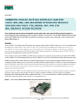
Figure 1 shows the slot numbering for the front view components of a fully loaded
Cisco uBR10012 router with the corresponding slot numbering (without bezel).
Figure 1
Cisco uBR10012 Router Slot Numbering—Front View (without bezel)
Cisco uBR10012 Universal Broadband Router Software Configuration Guide
1-6
OL-1520-08
Chapter 1
Overview of Cisco uBR10012 Universal Broadband Router Software
Cisco uBR10012 Universal Broadband Router Chassis Overview
Tip
The Fast Ethernet interface on the backup PRE module is not used unless the primary PRE module
fails and the backup PRE module is activated. When the backup PRE module becomes the active PRE
module, its FastEthernet interface automatically becomes the active FastEthernet interface at slot
0/0.
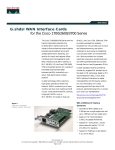
Figure 2 shows the rear view components of a fully loaded Cisco uBR10012 router with the
corresponding slot numbering.
Figure 2
Cisco uBR10012 Router Slot Numbering—Rear View
Cisco uBR10012 Universal Broadband Router Software Configuration Guide
OL-1520-08
1-7
Chapter 1
Overview of Cisco uBR10012 Universal Broadband Router Software
Cisco uBR10012 Universal Broadband Router Chassis Overview
Hardware Supported on the Cisco uBR10012 Router
Cisco IOS Release 12.3(9a)BC supports the following hardware on the Cisco uBR10012 router. This
and earlier descriptions of supported hardware are available in the release notes for your respective
Cisco IOS release.
Table 4
Cisco uBR10012 Universal Broadband Router Supported Hardware
Cable Interface Line cards
Up to eight of the following broadband processing engines and cable
interface line cards can be housed in a chassis in any combination:
•
Cisco uBR10-MC5X20S/U broadband processing engines
•
Cisco uBR10-LCP2-MC16C/MC16E/MC16S cable interface
line cards
•
Cisco uBR10-LCP2-MC28C cable interface line cards
Note
Network Uplink Line Cards
Timing, Communication and
Control Plus (TCC+) card
The Cisco uBR7200 Series MC28U BPE does not support the
Cisco uBR10012 router, though the Cisco MC28U BPE
physically fits into the Cisco uBR10012 router chassis.
Up to four line cards with any combination of the following WAN
choices:
•
Cisco uBR10-SRP-OC12SML DPT WAN Line Card for the
Cisco uBR10012 Router
•
Cisco uBR10012 OC-48 DPT/POS interface module
•
Cisco uBR10-1GE Gigabit Ethernet (GigE) uplink line card
•
Cisco uBR10-1OC12/P-SMI OC-12 POS uplink line card
•
Cisco uBR10-SRP-OC12SML Dynamic Packet Transport (DPT)
WAN card
The TCC+ card can connect to an external reference Stratum 3 clock
source that is traceable to a Stratum 1 source. Two such sources can
be connected for redundancy.
The TCC+ card also monitors the cable line cards and power supply
use, as well as control the LCD display screen on the chassis. Two
cards can be installed for redundancy.
Performance Routing Engine 2 The new Cisco uBR10012 Series PRE2 effectively doubles the
(PRE2)
bandwidth available to each slot on the router as supported by cable
interface line cards or Cisco Broadband Processing Engines.
The PRE2 module introduces support for full-duplex Gigabit
Ethernet ports, and increases the supported connections to 1.6 Gbps
in full duplex (each direction per half-slot). Full-slot modules can
now have up to 3.2 Gbps to and from the PRE2 module. This is twice
the connection rate of the Cisco uBR10012 PRE1 route processor
module.
Cisco uBR10012 Universal Broadband Router Software Configuration Guide
1-8
OL-1520-08
Chapter 1
Overview of Cisco uBR10012 Universal Broadband Router Software
Cisco uBR10012 Universal Broadband Router Chassis Overview
Table 4
Cisco uBR10012 Universal Broadband Router Supported Hardware
Performance Routing Engine
(PRE1 or PRE2)
One PRE1 or PRE2 module performs layer 2 and layer 3 packet
processing, as well as routing and system management functions.
Two PRE modules can be installed for redundancy.
Note
The PRE1 module is functionally identical to the PRE
module except that it adds support for the Error Checking and
Correction (ECC) feature, which can automatically correct
single-bit memory errors.
Note
The Cisco uBR10012 PRE1 module supports an Ethernet
port to a LAN for a 10BASE-T or 100BASE-T connection for
network management. The PRE1 module supports
connections of 800 Mbps in full duplex (each direction) per
half-slot.
AC-input Power Entry Module The Cisco uBR10012 router ships with two AC power entry modules
(PEM)
(AC PEMs) that provide a redundant power supply to the system.
One AC PEM can provide sufficient power for a fully configured
chassis, so that if one AC PEM fails, the other automatically begins
providing power for the entire router, without impacting system
operations.
The AC PEMs use standard 200–240 VAC (50/60 Hz) input power
obtained through power receptacles on the front panel of each PEM.
The two AC PEMs convert the AC power to provide filtered,
redundant, and load shared DC power to the Cisco uBR10012
chassis.
Caution
The Cisco uBR10012 router does not support mixing AC
and DC PEMs. Both PEMs must be either AC PEMs or DC
PEMs.
DC-input Power Entry Module The Cisco uBR10012 router may ship with two DC PEMs to provide
(PEM)
power to the chassis. The use of two PEMs provide power balancing
and redundancy, as well as the ability to hot-swap a single power
supply when needed.
Caution
Fan assembly module
The Cisco uBR10012 router does not support mixing AC
and DC PEMs. Both PEMs must be either AC PEMs or DC
PEMs.
The fan assembly module contains four fans that are capable of
cooling the chassis even with the failure of a single fan. The fan
assembly is dual-speed, providing additional cooling when the
chassis temperature exceeds the nominal operating range.
Cisco uBR10012 Universal Broadband Router Software Configuration Guide
OL-1520-08
1-9
Chapter 1
Overview of Cisco uBR10012 Universal Broadband Router Software
Supported Software Features for the Cisco uBR10012 Router
Supported Software Features for the Cisco uBR10012 Router
This section summarizes Cisco uBR10012 router software features for all supported Cisco IOS Release
trains, and directs you to additional configuration information for each feature.
Cisco uBR10012 Router Features and Cisco IOS Releases
Table 5 summarizes the software-related features and related Cisco IOS releases that support the
Cisco uBR10012 router. Cisco IOS features indicate the first release in which the feature was
introduced. Unless otherwise noted, feature support continues in later releases of the same or related
Cisco IOS release train.
Table 5
Cisco uBR10012 Router Features by Cisco IOS Release
Feature
Supporting Cisco IOS Releases
Cisco uBR10012 Router Configuration Tools
AutoInstall
12.2(1)XF1 and later 12.2 XF, 12.2 BC and 12.3 BC releases
Cable Interface Setup Facility
12.2(1)XF1 and later 12.2 XF, 12.2 BC and 12.3 BC releases
Cisco Network Registrar
12.2(1)XF1 and later 12.2 XF, 12.2 BC and 12.3 BC releases
Configuration Mode (Command Line Interface
Configuration)
12.2(1)XF1 and later 12.2 XF, 12.2 BC and 12.3 BC releases
Extended Setup Facility
12.2(1)XF1 and later 12.2 XF, 12.2 BC and 12.3 BC releases
Cisco IOS Release 12.3 BC Command-line Enhancements
Cisco IOS Release 12.3(9a)BC Command-Line Interface
(CLI) Enhancements
12.3(9a)BC and later 12.3 BC releases
DHCP Servers and Feature Support
DHCP MAC Address Exclusion List for cable-source verify
dhcp Command
Cisco IOS Release 12.3(13a)BC and later 12.3 BC releases.
Integrated DHCP Server
Multiple Cisco IOS releases and trains.
DOCSIS 1.0 Feature Support
DOCSIS 1.0 Baseline Privacy Interface
DOCSIS 1.0 BPI encryption and authentication supported in
Cisco IOS 12.2(1)XF1 and later 12.2 XF, 12.2 BC and 12.3 BC
releases
DOCSIS 1.0 Concatenation Override
12.3(13a)BC and later 12.3 BC releases
DOCSIS 1.0 Configuration File Settings
12.2(1)XF1 and later 12.2 XF, 12.2 BC and 12.3 BC releases
DOCSIS 1.0 Constant Bit Rate Extension
12.2(1)XF1 and later 12.2 XF, 12.2 BC and 12.3 BC releases
DOCSIS 1.0 MAC Driver
12.2(1)XF1 and later 12.2 XF, 12.2 BC and 12.3 BC releases
DOCSIS 1.0 Quality of Service Support
12.2(1)XF1 and later 12.2 XF, 12.2 BC and 12.3 BC releases
DOCSIS 1.0 Payload Header Suppression
12.2(1)XF1 and later 12.2 XF, 12.2 BC and 12.3 BC releases
DOCSIS 1.0 per SID Bandwidth Request and Grant Counters 12.2(1)XF1 and later 12.2 XF, 12.2 BC and 12.3 BC releases
DOCSIS 1.0 ToS Overwrite
12.3(17a)BC2 and later 12.3 BC releases.
Enhanced Rate Bandwidth Allocation (ERBA) Support for
DOCSIS 1.0 Cable Modems
12.3(13a)BC and later 12.3 BC releases
DOCSIS 1.0+ Feature Support
Cisco uBR10012 Universal Broadband Router Software Configuration Guide
1-10
OL-1520-08
Chapter 1
Overview of Cisco uBR10012 Universal Broadband Router Software
Supported Software Features for the Cisco uBR10012 Router
Table 5
Cisco uBR10012 Router Features by Cisco IOS Release (continued)
Feature
Supporting Cisco IOS Releases
DOCSIS 1.1 CM Compatibility
12.2(1)XF1 and later 12.2 XF, 12.2 BC and 12.3 BC releases
DOCSIS 1.1 Feature Support
DOCSIS 1.1 Baseline Privacy Interface Plus Features
12.2(1)XF1 and later 12.2 XF, 12.2 BC and 12.3 BC releases
DOCSIS BPI+ Multiple Root Certificate Support
12.3(13a)BC and later 12.3 BC releases
DOCSIS 1.1 CM Compatibility
12.2(1)XF1 and later 12.2 XF, 12.2 BC and 12.3 BC releases
DOCSIS 1.1 CM Database Manager
12.2(1)XF1 and later 12.2 XF, 12.2 BC and 12.3 BC releases
DOCSIS 1.1 Concatenation Support
12.2(1)XF1 and later 12.2 XF, 12.2 BC and 12.3 BC releases
See also DOCSIS 1.0 Concatenation Override
DOCSIS 1.1 Customer Premises Equipment Configurator
12.2(1)XF1 and later 12.2 XF, 12.2 BC and 12.3 BC releases
DOCSIS 1.1 Downstream Packet Classifier
12.2(1)XF1 and later 12.2 XF, 12.2 BC and 12.3 BC releases
DOCSIS 1.1 Downstream Packet Scheduler
12.2(1)XF1 and later 12.2 XF, 12.2 BC and 12.3 BC releases
DOCSIS 1.1 Dynamic MAC Messages
12.2(1)XF1 and later 12.2 XF, 12.2 BC and 12.3 BC releases
DOCSIS 1.1 Enhanced Registration
12.2(1)XF1 and later 12.2 XF, 12.2 BC and 12.3 BC releases
DOCSIS 1.1 Fragmentation and Reassembly
12.2(1)XF1 and later 12.2 XF, 12.2 BC and 12.3 BC releases
DOCSIS 1.1 Layer 2 Fragmentation
12.2(1)XF1 and later 12.2 XF, 12.2 BC and 12.3 BC releases
DOCSIS 1.1 MAC Scheduler
12.2(1)XF1 and later 12.2 XF, 12.2 BC and 12.3 BC releases
DOCSIS 1.1 Payload Header Suppression and Restoration
12.2(1)XF1 and later 12.2 XF, 12.2 BC and 12.3 BC releases
DOCSIS 1.1 Quality of Service Support
12.2(1)XF1 and later 12.2 XF, 12.2 BC and 12.3 BC releases
DOCSIS 1.1 Rate Limiting and Traffic Shaping
12.2(1)XF1 and later 12.2 XF, 12.2 BC and 12.3 BC releases
DOCSIS 1.1 Service Flow Manager
12.2(1)XF1 and later 12.2 XF, 12.2 BC and 12.3 BC releases
DOCSIS 1.1 Service Template and Class Manager
12.2(1)XF1 and later 12.2 XF, 12.2 BC and 12.3 BC releases
DOCSIS 1.1 Software Infrastructure
12.2(1)XF1 and later 12.2 XF, 12.2 BC and 12.3 BC releases
DOCSIS 1.1 Subscriber Management
12.2(1)XF1 and later 12.2 XF, 12.2 BC and 12.3 BC releases
DOCSIS 1.1 Time Slot Scheduling
12.2(1)XF1 and later 12.2 XF, 12.2 BC and 12.3 BC releases
DOCSIS 1.1 TLV Parser and Encoder
12.2(1)XF1 and later 12.2 XF, 12.2 BC and 12.3 BC releases
DOCSIS 1.1 Token-Bucket Rate Shaping
12.2(1)XF1 and later 12.2 XF, 12.2 BC and 12.3 BC releases
DOCSIS 1.1 Two-Way Interoperability
12.2(1)XF1 and later 12.2 XF, 12.2 BC and 12.3 BC releases
Optional Upstream Scheduler Modes
12.3(13a)BC and later 12.3 BC releases
High Availability Features
Automatic Revert Feature for HCCP N+1 Redundancy
Switchover Events
12.3(13a)BC and later 12.3 BC releases
Backup Path Testing for the Cisco RF Switch
12.3(13a)BC and later 12.3 BC releases
DSX Messages and Synchronized PHS Information
12.3(17a)BC and later 12.3 BC releases
Factory-Configured HCCP N+1 Redundancy
12.3(13a)BC and later 12.3 BC releases
Globally Configured HCCP 4+1 and 7+1 Redundancy on the 12.3(17a)BC and later 12.3 BC releases
Cisco uBR10012 Router
Cisco uBR10012 Universal Broadband Router Software Configuration Guide
OL-1520-08
1-11
Chapter 1
Overview of Cisco uBR10012 Universal Broadband Router Software
Supported Software Features for the Cisco uBR10012 Router
Table 5
Cisco uBR10012 Router Features by Cisco IOS Release (continued)
Feature
Supporting Cisco IOS Releases
HCCP N+1 Redundancy Supporting DOCSIS 1.1 for the
Cisco CMTS
12.2(1)XF1 and later 12.2 XF, 12.2 BC and 12.3 BC releases
HCCP Timing and Error Enhancements in HCCP
Redundancy Show Commands
12.3(13a)BC and later 12.3 BC releases
High Availability Support for Encrypted IP Multicast
12.3(17a)BC and later 12.3 BC releases
Shutdown and No Shutdown Enhancement for Cable
Interfaces
12.3(13a)BC and later 12.3 BC releases
Intercept Features
Access Control List Support for COPS Intercept
12.3(13a)BC and later 12.3 BC releases
Basic Wiretap Support
12.2(1)XF1 and later 12.2 XF, 12.2 BC and 12.3 BC releases
Cable Monitor Enhancements
12.3(17a)BC and later 12.3 BC releases
Cable Monitor Support for Cisco MC5x20U-D and Cisco
MC28U Broadband Processing Engines
12.3(13a)BC and later 12.3 BC releases
cable monitor Command
12.2(4)XF and later 12.2 XF, 12.2 BC and 12.3 BC releases
COPS TCP Support for the Cisco Cable Modem Termination 12.3(13a)BC and later 12.3 BC releases
System
Packet Intercept
12.2(1)XF1 and later 12.2 XF, 12.2 BC and 12.3 BC releases
PXF ARP Filter
12.3(17a)BC and later 12.3 BC releases
PXF Divert Rate Limiting
12.3(17a)BC and later 12.3 BC releases
Service Independent Intercept (SII) Support
12.3(13a)BC and later 12.3 BC releases
IP Broadcast and Multicast Features
IP Broadcast Echo
12.2(1)XF1 and later 12.2 XF, 12.2 BC and 12.3 BC releases
IP Multicast Echo
12.2(1)XF1 and later 12.2 XF, 12.2 BC and 12.3 BC releases
Multicast QoS Support on the Cisco uBR10012 CMTS
12.3(13a)BC and later 12.3 BC releases
SSM Mapping
12.3(17a)BC and later 12.3 BC releases
IP Routing Features
Cable ARP Filter Enhancement
12.3(9a)BC and later 12.3BC releases
Configurable Registration Timeout
12.2(1)XF1 and later 12.2 XF, 12.2 BC and 12.3 BC releases
DHCP MAC Address Exclusion List for cable-source
verify dhcp Command
12.3(13a)BC and later 12.3 BC releases
Host-to-Host Communication (Proxy Address Resolution
Protocol)
12.2(1)XF1 and later 12.2 XF, 12.2 BC and 12.3 BC releases
Integrated DHCP Server
12.2(1)XF1 and later 12.2 XF, 12.2 BC and 12.3 BC releases
Integrated Time-of-Day Server
12.2(1)XF1 and later 12.2 XF, 12.2 BC and 12.3 BC releases
PBR support for the Cisco uBR10012
12.2(11) CY and later CY releases
Supported Protocols
12.2(1)XF1 and later 12.2 XF, 12.2 BC and 12.3 BC releases
Management Features
Admission Control for the Cisco CMTS
12.3(13a)BC and later 12.3 BC releases
Cisco uBR10012 Universal Broadband Router Software Configuration Guide
1-12
OL-1520-08
Chapter 1
Overview of Cisco uBR10012 Universal Broadband Router Software
Supported Software Features for the Cisco uBR10012 Router
Table 5
Cisco uBR10012 Router Features by Cisco IOS Release (continued)
Feature
Supporting Cisco IOS Releases
Broadband Internet Access
12.2(1)XF1 and later 12.2 XF, 12.2 BC and 12.3 BC releases
Cable Interface Bundling
12.2(1)XF1 and later 12.2 XF, 12.2 BC and 12.3 BC releases
CNEM Compliance
12.3(17a)BC and later 12.3 BC releases
Customer Premises Equipment Limitation and Override
12.2(1)XF1 and later 12.2 XF, 12.2 BC and 12.3 BC releases
DOCSIS 2.0 SAMIS ECR Data Set
12.3(17a)BC and later 12.3 BC releases
DOCSIS Set-Top Gateway Issue 1.0
12.3(9a)BC and later 12.3 BC releases
Advanced-mode DOCSIS Set-Top Gateway Issue 1.1
12.3(13a)BC and later 12.3 BC releases
Advanced-mode DOCSIS Set-Top Gateway Issue 1.2
12.3(17a)BC2 and later 12.3 BC releases
Downstream Channel ID Configuration
12.2(1)XF1 and later 12.2 XF, 12.2 BC and 12.3 BC releases
Downstream Frequency Override
12.2(1)XF1 and later 12.2 XF, 12.2 BC and 12.3 BC releases
Downstream Load Balancing Distribution with Upstream
Load Balancing
12.3(17b)BC and later 12.3 BC releases
Dynamic Channel Change (DCC) for Loadbalancing
12.3(17a)BC and later 12.3 BC releases
Dynamic Modulation Profiles
12.2(1)XF1 and later 12.2 XF, 12.2 BC and 12.3 BC releases
Dynamic Upstream Modulation
12.2(1)XF1 and later 12.2 XF, 12.2 BC and 12.3 BC releases
EtherChannel Support on the Cisco uBR10012 Universal
Broadband Router
12.3(9a)BC and later 12.3 BC releases
Management Information Base (MIB) Changes and
Enhancements
12.3(17a)BC and later 12.3 BC releases
MIBs Changes and Updates in Cisco IOS Release
12.3(9a)BC
12.3(9a)BC and later 12.3 BC releases
Pre-equalization Control for Cable Modems
12.3(17a)BC and later 12.3 BC releases
Route Processor Redundancy Support
12.2(4)XF 12.2 XF , 12.2 BC and 12.3 BC releases
Secure Socket Layer Server for Usage-Based Billing
12.3(17a)BC and later 12.3 BC releases
SFID Support for Multicast and Cable Interface Bundling
12.3(9a)BC and later 12.3 BC releases
Simple Network Management Protocol Cable Modem
Remote Query
12.2(4)BC1b and later 12.2 BC and 12.3 BC releases
Simple Network Management Protocol v3
12.2(1)XF1 and later 12.2 XF, 12.2 BC and 12.3 BC releases
Spectrum Management
12.2(1)XF1 and later 12.2 XF, 12.2 BC and 12.3 BC releases
Advanced Spectrum Management Support on the Cisco
uBR10012 CMTS
12.3(13a)BC and later 12.3 BC releases
Static CPE Override (cable submgmt default Command)
12.3(9a)BC and later 12.3 BC releases
Statistical Counters
12.2(1)XF1 and later 12.2 XF, 12.2 BC and 12.3 BC releases
Subscriber Traffic Management (STM) Version 1.1
12.3(9a)BC and later 12.3 BC releases
Usage Based Billing (SAMIS)
12.3(9a)BC and later 12.3 BC releases
PacketCable and Voice Support Features
PacketCable 1.0 With CALEA
12.3(9a)BC and later 12.3 BC releases
Cisco uBR10012 Universal Broadband Router Software Configuration Guide
OL-1520-08
1-13
Chapter 1
Overview of Cisco uBR10012 Universal Broadband Router Software
Supported Software Features for the Cisco uBR10012 Router
Table 5
Cisco uBR10012 Router Features by Cisco IOS Release (continued)
Feature
Supporting Cisco IOS Releases
PacketCable Emergency 911 Cable Interface Line Card
Prioritization
12.3(13a)BC and later 12.3 BC releases
PacketCable Emergency 911 Services Listing and History
12.3(13a)BC and later 12.3 BC releases
Packetcable Multimedia for the Cisco CMTS
12.3(13a)BC and later 12.3 BC releases
Security Features
Address Verification
12.2(1)XF1 and later 12.2 XF, 12.2 BC and 12.3 BC releases
CM Transmission Burst Size
12.2(1)XF1 and later 12.2 XF, 12.2 BC and 12.3 BC releases
Dynamic or Mobile Host Support
12.2(1)XF1 and later 12.2 XF, 12.2 BC and 12.3 BC releases
Dynamic Shared Secret (DMIC) with OUI Exclusion
12.3(9a)BC and later 12.3 BC releases
Testing, Troubleshooting and Diagnostic Features
Cisco Broadband Troubleshooter 3.2
12.3(9a)BC and later 12.3 BC releases
CBT 3.2 Spectrum Management Support with the Cisco
uBR10-MC5X20S/U BPE
12.3(9a)BC and later 12.3 BC releases
Dynamic Ranging
12.2(1)XF1 and later 12.2 XF, 12.2 BC and 12.3 BC releases
Flap List Support
12.2(1)XF1 and later 12.2 XF, 12.2 BC and 12.3 BC releases
Online Offline Diagnostics (OOD) Support for the Cisco
uBR10012 Universal Broadband Router
12.3(13a)BC and later 12.3 BC releases
Virtual Interfaces
Virtual Interface and Frequency Stacking Support on the
Cisco uBR10-MC5X20S/U BPE
12.3(9a)BC and later 12.3 BC releases
Virtual Interface Support for HCCP N+1 Redundancy
12.3(9a)BC and later 12.3 BC releases
Virtual Interface Bundling on the
Cisco uBR10-MC5X20S/U BPE
12.3(13a)BC and later 12.3 BC releases
VLAN Features
12.2(11)CY and later 12.2 CY releases
VPN and Layer 2 Tunneling Features
Dynamic SID/VRF Mapping Support
12.3(13a)BC and later 12.3 BC releases
Generic Routing Encapsulation (GRE) Tunneling on the
Cisco uBR10012
12.3(17a)BC and later 12.3 BC releases
IPv6 over L2VPN
12.3(17a)BC and later 12.3 BC releases
MPLS-VPN Network Support
12.2(1)XF1 and later 12.2 XF, 12.2 BC and 12.3 BC releases
NetFlow Accounting Versions 5 and 8 Support
12.3(9a)BC and later 12.3 BC releases
Transparent LAN Service (TLS) on the Cisco uBR10012
Router with IEEE 802.1Q
12.3(9a)BC and later 12.3 BC releases
Transparent LAN Service and Layer 2 Virtual Private
Networks
12.3(13a)BC and later 12.3 BC releases
Cisco uBR10012 Universal Broadband Router Software Configuration Guide
1-14
OL-1520-08
Chapter 1
Overview of Cisco uBR10012 Universal Broadband Router Software
Supported Software Features for the Cisco uBR10012 Router
Cisco uBR10012 Router Configuration Tools
The Cisco uBR10012 Universal Broadband Router provides you with the following configuration tools,
allowing you flexibility in choosing your configuration method:
•
AutoInstall
•
Cable Interface Setup Facility
•
Cisco Network Registrar
•
Configuration Mode (Command Line Interface Configuration)
•
Extended Setup Facility
AutoInstall
The AutoInstall process configures the Cisco uBR10012 router automatically after connection to your
WAN. For additional information, refer to the “Configuring the Cisco uBR10012 Router Using
AutoInstall” section on page 7.
Cable Interface Setup Facility
The Cisco uBR10012 router Setup facility (also called the System Configuration dialog) is a useful and
efficient tool for configuring your CMTS. The Setup facility supports the a number of functions so that
cable interfaces and cable interface line cards are fully operational (after initial setup). Refer to the
“Configuring the Cisco uBR10012 Router Using the Setup Facility” section on page 8.
Configuration Mode (Command Line Interface Configuration)
The Configuration mode allows you to configure the Cisco uBR10012 router manually if you prefer not
to use Autoinstall or the Cable Interface Setup facility. For additional information, refer to the
“Configuring the Cisco uBR10012 Router Manually Using Configuration Mode” section on page 13.
Cisco Network Registrar
Cisco provides the Cisco Network Registrar with each Cisco uBR10012 router.
Cisco Network Registrar dramatically improves the reliability of naming and addressing services for
enterprise and service provider networks. Cisco Network Registrar provides scalable Domain Name
System (DNS) and Dynamic Host Configuration Protocol (DHCP) services and forms the basis of a
DOCSIS CM provisioning system.
Cisco Network Registrar is a configuration tool that automates dynamic IP address allocation to
cable interfaces, PCs, and other devices on the broadband network. Cisco Network Registrar allows you
to track serial numbers and MAC addresses for each cable interface on your network, and reduces
customer service involvement when tracking subscriber CPE equipment.
For additional information about configuring or using Cisco Network Registrar, refer to the latest
Cisco Network Registrar documentation at the Cisco Web site (http://www.cisco.com). One such
document is Installing the Cisco Network Registrar for the Cisco uBR7200 series routers, and the
Cisco Subscriber Registration Center Device Provisioning Registrar 2.0, both located on Cisco.com.
Extended Setup Facility
The Cable Interface Setup facility (described previously in this section) creates an initial CMTS
configuration. The Extended Setup facility prompts you to configure each interface on the system as you
progress through the CMTS configuration. For additional information, refer to the “Configuring the
Cable Interface with the Extended Setup Facility” section on page 14.
Cisco uBR10012 Universal Broadband Router Software Configuration Guide
OL-1520-08
1-15
Chapter 1
Overview of Cisco uBR10012 Universal Broadband Router Software
Supported Software Features for the Cisco uBR10012 Router
Cisco IOS Release 12.3 BC Command-line Enhancements
This section describes general Cisco IOS commands introduced or enhanced in Cisco IOS Release
12.3(9a)BC and later releases in the 12.3 BC release train. Also refer to additional feature descriptions
for new or enhanced commands that support specific new features.
•
Cisco IOS Release 12.3(13a)BC Command-Line Interface (CLI) Enhancements
•
Cisco IOS Release 12.3(9a)BC Command-Line Interface (CLI) Enhancements
Cisco IOS Release 12.3(13a)BC Command-Line Interface (CLI) Enhancements
Cisco IOS release 12.3(13a)BC introduces several new or enhanced commands. For this release, these
feature-specific commands or enhancements are described with the features they support. Refer to
additional feature descriptions in this document for additional information.
Cisco IOS Release 12.3(9a)BC Command-Line Interface (CLI) Enhancements
Cisco IOS Release 12.3(9a)BC introduces or enhances the following CLI commands for the
Cisco uBR10012 router:
•
cable arp filter (See Cable ARP Filter Enhancement)
•
cable logging layer2events
•
cable source-verify
•
show cable tech-support
•
show controllers cable
•
show tech-support
For additional information about these command changes, refer to these resources:
•
Cisco Broadband Cable Command Reference Guide
http://www.cisco.com/univercd/cc/td/doc/product/cable/bbccmref/index.htm
DHCP Servers and Feature Support
Cisco IOS software supports multiple DHCP features and server functions on the network for the
Cisco uBR10012 router:
•
DHCP MAC Address Exclusion List for cable-source verify dhcp Command
•
Integrated DHCP Server
DHCP MAC Address Exclusion List for cable-source verify dhcp Command
Cisco IOS Release 12.3(13a)BC introduces the ability to exclude trusted MAC addresses from standard
DHCP source verification checks, as supported in previous Cisco IOS releases for the Cisco CMTS. This
feature enables packets from trusted MAC addresses to pass when otherwise packets would be rejected
with standard DHCP source verification. This feature overrides the cable source-verify command on
the Cisco CMTS for the specified MAC address, yet maintains overall support for standard and enabled
DHCP source verification processes. This feature is supported on Performance Routing Engine 1 (PRE1)
and PRE2 modules on the Cisco uBR10012 router chassis.
Cisco uBR10012 Universal Broadband Router Software Configuration Guide
1-16
OL-1520-08
Chapter 1
Overview of Cisco uBR10012 Universal Broadband Router Software
Supported Software Features for the Cisco uBR10012 Router
To enable packets from trusted source MAC addresses in DHCP, use the cable trust command in global
configuration mode. To remove a trusted MAC address from the MAC exclusion list, use the no form of
this command. Removing a MAC address from the exclusion list subjects all packets from that source
to standard DHCP source verification.
cable trust mac-address
no cable trust mac-address
Syntax Description
mac-address
Usage Guidelines
This command and capability are only supported in circumstances in which the Cable Source Verify
feature is first enabled on the Cisco CMTS.
The MAC address of a trusted DHCP source, and from which packets will
not be subject to standard DHCP source verification.
When this feature is enabled in addition to cable source verify, a packet’s source must belong to the
MAC Exclude list on the Cisco CMTS. If the packet succeeds this exclusionary check, then the source
IP address is verified against Address Resolution Protocol (ARP) tables as per normal and previously
supported source verification checks. The service ID (SID) and the source IP address of the packet must
match those in the ARP host database on the Cisco CMTS. If the packet check succeeds, the packet is
allowed to pass. Rejected packets are discarded in either of these two checks.
Any trusted source MAC address in the optional exclusion list may be removed at any time. Removal of
a MAC address returns previously trusted packets to non-trusted status, and subjects all packets to
standard source verification checks on the Cisco CMTS.
For additional information about the enhanced Cable Source Verify DHCP feature, and general
guidelines for its use, refer to the following documents on Cisco.com:
•
IP Address Verification for the Cisco uBR7200 Series Cable Router
http://www.cisco.com/en/US/products/sw/iosswrel/ps1830/products_feature_guide09186a0080087b55.html
•
Filtering Cable DHCP Lease Queries
http://www.cisco.com/en/US/products/hw/cable/ps2217/products_feature_guide09186a008021b8fb.html
•
Cisco Broadband Cable Command Reference Guide
http://www.cisco.com/en/US/products/hw/cable/ps2217/products_command_reference_book0918
6a0080108e88.html
•
CABLE SECURITY, Cable Source-Verify and IP Address Security, White Paper
http://www.cisco.com/en/US/tech/tk86/tk803/technologies_tech_note09186a00800a7828.shtml
Integrated DHCP Server
This network management feature simplifies provisioning, offering an integrated Dynamic Host
Configuration Protocol server. For information about configuring DHCP, ToD, or TFTP services, refer
to the chapter titled “Configuring DHCP, ToD, and TFTP Services” in the Cisco Cable Modem
Termination System Feature Guide on Cisco.com.
Cisco uBR10012 Universal Broadband Router Software Configuration Guide
OL-1520-08
1-17
Chapter 1
Overview of Cisco uBR10012 Universal Broadband Router Software
Supported Software Features for the Cisco uBR10012 Router
DOCSIS 1.0 Feature Support
The Cisco uBR10012 router and associated Cisco IOS software support multiple DOCSIS 1.0
enhancements, extensions, and features.
•
DOCSIS 1.0 Baseline Privacy Interface
•
DOCSIS 1.0 Concatenation Override
•
DOCSIS 1.0 Configuration File Settings
•
DOCSIS 1.0 Constant Bit Rate Extension
•
DOCSIS 1.0 MAC Driver
•
DOCSIS 1.0 Quality of Service Support
•
DOCSIS 1.0 Payload Header Suppression
•
DOCSIS 1.0 per SID Bandwidth Request and Grant Counters
•
Enhanced Rate Bandwidth Allocation (ERBA) Support for DOCSIS 1.0 Cable Modems
For additional information about configuring DOCSIS QoS and other DOCSIS features, refer to the
DOCSIS 1.1 Feature Module for the Cisco uBR7200 Routers on Cisco.com, and to other documents cited
for DOCSIS 1.0 features below.
Caution
All DOCSIS 1.0 extensions are activated only when a CM or equivalent device that supports these
extensions solicits services using dynamic MAC messages. If the CMs in your network are all
DOCSIS 1.0-based, they receive regular DOCSIS 1.0 treatment from the CMTS.
DOCSIS 1.0 Baseline Privacy Interface
The Cisco uBR10012 router supports full DOCSIS 1.0 Baseline Privacy Interface (BPI) specifications. The
BPI for DOCSIS 1.0 protects user data privacy across the shared-medium cable network and prevents
unauthorized access to DOCSIS-based data transport services across the cable network. BPI encrypts traffic
across the RF interface between the CM and CMTS, and includes authentication, authorization, and
accounting (AAA) features.
The level of data privacy is roughly equivalent to that provided by dedicated line network access services
such as analog modems or digital subscriber lines (DSL). BPI provides basic protection of service,
ensuring that a CM, uniquely identified by its MAC address, can obtain keying material for services only
when it is authorized to access them.
Note
Encryption and decryption are subject to export licensing controls.
BPI supports access control lists (ACLs), tunnels, filtering, protection against spoofing, and commands
to configure source IP filtering on RF subnets to prevent subscribers from using source IP addresses that
are not valid.
Cisco uBR10012 Universal Broadband Router Software Configuration Guide
1-18
OL-1520-08
Chapter 1
Overview of Cisco uBR10012 Universal Broadband Router Software
Supported Software Features for the Cisco uBR10012 Router
Note
To conform with a recent change in the DOCSIS 1.0 Baseline Privacy Interface (BPI) Specification,
Cisco IOS Release 12.2(8)BC1 and later releases require that the Baseline Privacy Configuration
Settings Option (Type 17) must be included in the DOCSIS configuration file for all DOCSIS 1.0 cable
modems attempting to register for BPI encryption. If the type 17 option is not included, an
"Unauthorized SAID" warning will appear in the CMTS console, and the cable modem will not be
allowed to come online.
Previous Cisco IOS releases allowed DOCSIS 1.0 cable modems to register for BPI encryption and to
come online, even if the DOCSIS configuration file did not include the type 17 option. The change to
the DOCSIS BPI specification, however, made the type 17 option mandatory for BPI operation.
For more information about this requirement, see the TAC technical note on Cisco.com at
http://www.cisco.com/warp/public/109/bpi_changes_23895.html.
DOCSIS 1.0 Concatenation Override
Cisco IOS release 12.3(13a)BC introduces support for the DOCSIS 1.0 concatenation override feature
on the Cisco uBR10012 router. This feature provides the ability to disable concatenation on DOCSIS 1.0
cable modems, even in circumstances where concatenation is otherwise supported for the upstream
channel.
DOCSIS 1.0 concatenation allows the cable modem to make a single-time slice request for multiple
packets, and to send all packets in a single large burst on the upstream. Concatenation was introduced
in the upstream receive driver in the previous Cisco IOS releases that supported DOCSIS 1.0 +. Per-SID
counters were later added in Cisco IOS release 12.1(4)CX for debugging concatenation activity.
In some circumstances, overriding concatenation on DOCSIS 1.0 cable modems may be preferable, and
Cisco IOS release 12.3(13a)BC supports either option.
Note
Even when DOCSIS 1.0 concatenation is disabled with this feature, concatenation remains enabled for
cable modems that are compliant with DOCSIS 1.1 or DOCSIS 2.0.
To enable DOCSIS 1.0 concatenation override with Cisco IOS release 12.3(13a)BC and later releases,
use the new docsis10 keyword with the previously supported cable upstream <n> concatenation
command in privileged EXEC mode:
cable upstream <n> concatenation docsis10
Syntax Description
n
Examples
The following example illustrates DOCSIS 1.0 concatenation override on the Cisco uBR10012 router:
Specifies the upstream port number. Valid values start with 0 for the first
upstream port on the cable interface line card.
Router# no cable upstream 0 concatenation docsis10
In this example, DOCSIS 1.0 cable modems are updated with REG-RSP so that they are not permitted
to use concatenation.
For additional information about this command, refer to the Cisco Broadband Cable Command
Reference Guide on Cisco.com:
http://www.cisco.com/en/US/products/hw/cable/ps2217/products_command_reference_book0918
6a0080108e88.html
Cisco uBR10012 Universal Broadband Router Software Configuration Guide
OL-1520-08
1-19
Chapter 1
Overview of Cisco uBR10012 Universal Broadband Router Software
Supported Software Features for the Cisco uBR10012 Router
DOCSIS 1.0 Configuration File Settings
Refer to these sections for additional information about DOCSIS configuration files:
•
“DOCSIS 1.0 Constant Bit Rate Extension” section on page 20
•
“DOCSIS 1.0 Traffic Shaping and Rate Limiting Features” section on page 23
•
“DOCSIS 1.1 Subscriber Management” section on page 37
For additional information about configuring DOCSIS QoS and other DOCSIS features, refer to the DOCSIS
1.1 Feature Module for the Cisco uBR7200 Routers on Cisco.com and to other documents cited below.
DOCSIS 1.0 Constant Bit Rate Extension
This DOCSIS 1.0 extension enables better processing of higher-priority traffic; fields in the DOCSIS
configuration file can be used so that when a CM requests a voice SID, the MAC scheduler on the
Cisco uBR10012 router schedules fixed periodic slots on the upstream for that traffic flow. The CM does
not have to contend for these slots and, because the Cisco uBR10012 router controls the timing of slots,
it has precise control over potential delay and jitter.
DOCSIS 1.0 MAC Driver
This DOCSIS 1.0 driver supports CableLabs specifications for the MAC sublayer and associated
interfaces. Refer to the “DOCSIS 1.0 MAC Enhancements to Improve Upstream per CM Data
Throughput” section on page 20.
DOCSIS 1.0 Quality of Service Support
Cisco uBR10012 router software offers DOCSIS 1.0 Quality of Service (QoS) support. This allows you
to define service levels in order to map data packets efficiently into traffic classes. These traffic classes
determine how network resources are allocated and controlled. QoS can be delivered through a
combined use of IP precedence ToS bits and QoS capabilities of IP and ATM core networks.
Cisco uBR10012 router software supports varying QoS definitions for differentiated services:
•
Guaranteed-rate service queue to store bandwidth requests from CMs subscribing to a class with
minimum upstream rate on the upstream channel.
• Best-effort service queue to store bandwidth requests from CMs subscribing to a class with no
minimum upstream rate on the upstream channel.
• Service priority of 7 to 0; a higher value indicates better service.
• Maximum allowed upstream rate in bps.
• Maximum upstream channel burst in minislots.
• Minimum reserved upstream rate in bps.
• Maximum allowed downstream rate in bps.
Additional information about the capabilities and configuration of DOCSIS QoS are described the
following documents:
•
•
DOCSIS 1.1 Feature Module for the Cisco uBR7200 Routers
Cisco IOS Quality of Service Solutions Configuration Guide, Release 12.2
•
Cisco IOS Quality of Service Solutions Command Reference, Release 12.2
DOCSIS 1.0 MAC Enhancements to Improve Upstream per CM Data Throughput
DOCSIS 1.0 supports tiered best-effort and CIR-type service. The Cisco uBR10012 router and CMTS
now support a mechanism to dynamically initiate and terminate MAC-level scheduling for high-priority
traffic, and to specify exactly what QoS parameters to use.
Cisco uBR10012 Universal Broadband Router Software Configuration Guide
1-20
OL-1520-08
Chapter 1
Overview of Cisco uBR10012 Universal Broadband Router Software
Supported Software Features for the Cisco uBR10012 Router
In DOCSIS 1.0, the CM explicitly requests upstream bandwidth—either in contention or piggyback to
grant minislots—for every single packet it wants to send upstream. This limits the maximum upstream
data throughput that a CM can receive due to the inherent “request to grant” round-trip latency each
packet incurs on the cable system. To support this per-cable-modem upstream throughput increase, the
Cisco uBR10012 router software is enhanced. The CMTS can now receive a concatenated burst of
multiple MAC frames from the same CM.
Note
Both the CMTS and CM must support this capability.
DOCSIS 1.0 Downstream Rate Shaping with Type of Service (ToS)
This feature supports buffering downstream grants to rate-exceeding cable interfaces, without incurring
TCP-related timeouts and retransmits. This feature uses the three precedence bits in the ToS field in the
IP header to specify class of service assignment for each packet.
Those packets with the IP precedence bit set in the IP packet are given higher priority. This allows the
CMTS administrator to calculate the data rate for a given flow, in addition to the data rate configured on
a per CM basis.
IP Precedence-Based Downstream Rate Limits
DOCSIS 1.0 provides QoS, based on the SID. Each QoS profile carries a parameter maximum
downstream rate, which is used to provide peak rate limiting and traffic shaping on the downstream.
When higher-priority and traffic data are combined for a particular CM, rate-exceeded data packets
might shut down or delay higher-priority packets, thereby degrading quality. IP precedence bits can be
used as a basic differentiator to provide independent rate limits for different traffic streams.
DOCSIS 1.0 Downstream Signal Test Commands
The cable downstream if-output command provides several test capabilities and is enhanced with the
following options to generate test signals on the downstream interface.
Note
•
cable downstream if-output prbs—Shuts down the downstream interface and outputs a
Pseudo-Random Bit Stream (PRBS) test signal.
•
cable downstream if-output continuous wave—Shuts down the downstream interface and outputs
an unmodulated carrier signal.
The previous cable downstream if-output command has not changed and continues to output a
standard modulated signal. The no cable downstream if-output command has not changed and stops
all signal output and shuts down the interface.
For additional command information, refer to the Cisco Broadband Cable Command Reference Guide.
DOCSIS 1.0 Modem Power Enhancement Adjustments for Low SNR Failures
This feature allows Cisco uBR10012 router to adjust better when a CM seems to bounce—the CM
requires frequent power adjustments in opposite directions. When this occurs, instead of making large
power adjustments for each correction, the administrator can configure the Cisco uBR10012 router to
calculate the average value of the power corrections before making power adjustments:
•
cable upstream power-adjust threshold—This command now accepts a range of 0 to 10 dB (the
previous range was 0 to 2 dB).
•
cable upstream power-adjust noise % of power adjustment—This command sets the threshold
value (in percent) for a particular upstream, switching between regular power adjustments and the
noise power-adjustment method.
The noise power-adjustment method uses an averaging algorithm before sending any correction. For
additional command information, refer to the Cisco Broadband Cable Command Reference Guide.
Cisco uBR10012 Universal Broadband Router Software Configuration Guide
OL-1520-08
1-21
Chapter 1
Overview of Cisco uBR10012 Universal Broadband Router Software
Supported Software Features for the Cisco uBR10012 Router
DOCSIS 1.0 Multi SID Support
This feature allows the Cisco uBR10012 router to support the definition of multiple SIDs on the
upstream. This includes multiple service classes per cable interface, enabling administrators to delegate
higher priority as required.
Note
•
Higher-priority traffic can be designated on a higher QoS committed information rate (CIR)
secondary SID, while data traffic can be forwarded on a best-effort basis on a primary SID.
•
Secondary SIDs can be defined to provide higher QoS CIR-type classes for higher-priority traffic. These
classes have a nonzero minimum reserved rate (CIR-type service). These SIDs, therefore, receive
preferential treatment at the CMTS for grants over any tiered best-effort type data SID for that upstream.
Best-effort service involves requests with no minimum upstream rate on the channel. The CMTS
treats the primary and secondary SIDs independently for issuing grants. Each SID of a CM has an
independent state machine. Channel access for each SID is independent of the other SID.
•
Cable-modem-initiated dynamic MAC messages—Dynamic Service Addition (DSA) and Dynamic
Service Deletion (DSD). These messages allow dynamic SIDs to be created and deleted at run time.
•
Unsolicited grant service (CBR-scheduling) on the upstream helps provide a higher-quality channel
for upstream packets from the Cisco uBR924 cable access router, for example.
Caution
Reliable operation with higher-priority traffic requires multiple SIDs—at least two per
cable interface to separate highest-priority traffic from data traffic. In DOCSIS 1.0, SIDs are
set up statically. When supporting extensions to DOCSIS 1.0 or DOCSIS 1.1, SIDs can be set
up either statically or dynamically. Both the CMTS and CM must support the feature set.
DOCSIS 1.0 QoS Profile Enforcement
QoS profile enforcement allows you to override the provisioned service class of a cable interface at the time
of registration with a CMTS-defined QoS profile. When this feature is enabled, the CMTS provisions each
registering CM with a default DOCSIS 1.0 service class, which the CMTS administrator configures.
The administrator-defined service class is enforced on CMs attempting to register with the CMTS. The
service class has no upstream or downstream rate limits.
When the CM sends data upstream, it makes bandwidth requests without throttling or dropping packets
because of its own rate-policing algorithm. The CMTS does traffic shaping based on the QoS profile
enforced by the operator.
Note
By default, the system does not enforce a specific QoS profile on the cable interface. The QoS profile
assigned to the cable interface depends on the class of service parameters provisioned in the cable
interface DOCSIS configuration file.
DOCSIS 1.0 RFC 2233 Support (RF Interface MIB)
The Cisco uBR10012 router supports DOCSIS OSSI Required Objects in RFC 2233.
DOCSIS 1.0 Service Class Profiles
The Cisco uBR10012 router allows you to create multiple service class profiles with the following
characteristics:
•
A specific QoS profile number
•
Traffic priority (7, 6, 5, 4, 3, 2, 1, 0), with 7 being the highest
•
Maximum and guaranteed upstream rate in bps
•
Maximum upstream channel burst in minislot
•
Minimum upstream rate in bps
Cisco uBR10012 Universal Broadband Router Software Configuration Guide
1-22
OL-1520-08
Chapter 1
Overview of Cisco uBR10012 Universal Broadband Router Software
Supported Software Features for the Cisco uBR10012 Router
•
Maximum downstream rate in bps
•
Maximum transmit burst length
•
ToS overwrite byte
Using these service class profiles, you can define a guaranteed-rate service queue to store bandwidth requests
from CMs subscribing to a class with minimum upstream rate on the upstream channel, and a best-effort
service queue for CMs subscribing to a class with no minimum upstream rate on the upstream channel.
The Cisco uBR10012 router also supports multiple service classes per CM and dynamic service identifiers.
This allows the Cisco uBR10012 router to dynamically allocate and delete service flows.
The CMTS also supports QoS profile enforcement to override interference from cable modems that might be
improperly rate limited. The CMTS system administrator can assign a default DOCSIS 1.0 service class that
overrides a pre-existing service class on the modem. The CMTS can do traffic shaping based on the QoS
profile the administrator enforces.
DOCSIS 1.0 Traffic Shaping and Rate Limiting Features
Traffic shaping reduces the chance that information is retransmitted to hosts on the HFC network and,
therefore, conserves bandwidth. Without traffic shaping, the Cisco IOS Release 12.2XF software drops
bandwidth requests from CMs found to be exceeding their configured peak upstream transmission rate.
Dropping bandwidth requests (and eventually upstream packets) from rate-exceeding cable interface
causes TCP-related timeouts, which cause the host sending the information to retransmit its information.
The Cisco IOS Release 12.2XF supports the following traffic shaping features:
•
Note
Downstream rate limiting—Allows downstream grants to rate-exceeding CMs to be buffered
without incurring TCP-related timeouts and retransmits. Downstream rate shaping enables you to
partition downstream traffic for a CM into multiple classes of service and multiple data rates by
using the three precedence bits in the ToS byte in the IP header to specify a class of service
assignment for each packet. Those packets with the precedence bit set in the ToS field are given
higher priority.
Using the ToS byte, you can calculate the data rate for a specified flow, in addition to the data rate
configured on a per-CM basis. By specifying a maximum data rate for a particular ToS, you can
override the common maximum downstream data rate.
Packets that contain ToS bytes that have not been configured for downstream data rates continue to use
the common data rate limits.
•
Upstream rate limiting—Allows upstream bandwidth requests from rate-exceeding CMs to be
buffered without incurring TCP-related timeouts and retransmits. This enables the CMTS to enforce
the peak upstream rate for each CM without degrading overall TCP performance for the subscriber
CPEs. Upstream grant shaping is per cable interface (SID).
Token-bucket policing with shaping is the per-upstream default rate-limiting setting at the CMTS.
Shaping can be enabled or disabled for the token-bucket algorithm.
Upstream traffic shaping delays the scheduling of an upstream packet, which causes the packet to
be buffered on the cable CPE device instead of being dropped. This allows the TCP/IP stack to pace
the application traffic appropriately and approach throughput commensurate with the subscriber’s
defined QoS levels.
DOCSIS 1.0 Payload Header Suppression
Payload Header Suppression (PHS) conserves link-layer bandwidth by suppressing unnecessary packet
headers on both upstream and downstream traffic flows. For configuration information, refer to the
“Configuring Payload Header Suppression and Restoration” section on page 27.
Cisco uBR10012 Universal Broadband Router Software Configuration Guide
OL-1520-08
1-23
Chapter 1
Overview of Cisco uBR10012 Universal Broadband Router Software
Supported Software Features for the Cisco uBR10012 Router
DOCSIS 1.0 per SID Bandwidth Request and Grant Counters
This feature promotes better control of higher-priority traffic, permitting per-SID bandwidth requests
and grants. Profiles can be customized for scheduling parameters required at subscriber sites for the
service offering.
The show interface cx/y/z sid counter command also supports a verbose option that displays:
•
Number of bandwidth requests successfully received by the Cisco uBR10012 router from the
specified SID on the specified cable interface
•
Number of grants issued by the Cisco uBR10012 router to the specified SID
DOCSIS 1.0 ToS Overwrite
Cisco IOS release 12.3(17a)BC2 introduces support for the DOCSIS 1.0 Type of Service (ToS)
Overwrite feature. Currently, ToS overwrite requires the creation of static cable QoS profiles, which are
then assigned to the ToS fields. This implementation works well if only a few different service types are
offered. However, scalability issues arise when large numbers of service types are presented; each
requiring a static QoS profile in order to perform ToS overwrite.
The Default DOCSIS 1.0 ToS Overwrite feature eliminates the need to create multiple QoS profiles in
order to perform type-of-service (ToS) overwrite by automatically bounding all DOCSIS 1.0 Cable
Modem (CM) created profiles to a default ToS overwrite.
Enhanced Rate Bandwidth Allocation (ERBA) Support for DOCSIS 1.0 Cable Modems
Cisco IOS release 12.3(13a)BC introduces Enhanced Rate Bandwidth Allocation (ERBA) support for
DOCSIS 1.0 cable modems and the Cisco uBR10012 router. ERBA allows DOCSIS1.0 modems to burst
their temporary transmission rate up to the full line rate for short durations of time. This capability
provides higher bandwidth for instantaneous bandwidth requests, such as those in Internet downloads,
without having to make changes to existing service levels in the QoS Profile.
This feature enables MSOs to set the DOCSIS 1.0 cable modems burst transmissions, with mapping to
overriding DOCSIS 1.1 QoS profile parameters on the Cisco CMTS. DOCSIS 1.0 cable modems require
DOCSIS 1.0 parameters when registering to a matching QoS profile. This feature enables maximum
downstream line rates, and the ERBA setting applies to all cable modems that register to the
corresponding QoS profile.
Note
QoS definitions must previously exist on the Cisco CMTS headend to support this feature.
ERBA for DOCSIS 1.0 cable modems is supported with these new or enhanced commands or keywords
in Cisco IOS release 12.3(13a)BC:
•
cable qos pro max-ds-burst burst-size
•
show cable qos profile n [verbose]
To define ERBA on the downstream for DOCSIS 1.0 cable modems, use the cable qos promax-ds-burst
command in global configuration mode. To remove this ERBA setting from the QoS profile, use the no
form of this command.
cable qos pro max-ds-burst burst-size
no cable qos pro max-ds-burst
Cisco uBR10012 Universal Broadband Router Software Configuration Guide
1-24
OL-1520-08
Chapter 1
Overview of Cisco uBR10012 Universal Broadband Router Software
Supported Software Features for the Cisco uBR10012 Router
Syntax Description
burst-size
The QoS profile’s downstream burst size in bytes.
To display ERBA settings as applied to DOCSIS 1.0 cable modems and QoS profiles on the Cisco
CMTS, use the show cable qos profile command in Privileged EXEC mode.
The following example of the cable qos profile command in global configuration mode illustrates
changes to the cable qos profile command. Fields relating to the ERBA feature are shown in bold for
illustration:
Router(config)# cable qos pro 10 ?
grant-interval
Grant interval
grant-size
Grant size
guaranteed-upstream Guaranteed Upstream
max-burst
Max Upstream Tx Burst
max-ds-burst
Max Downstream Tx burst (cisco specific)
max-downstream
Max Downstream
max-upstream
Max Upstream
name
QoS Profile name string (cisco specific)
priority
Priority
privacy
Cable Baseline Privacy Enable
tos-overwrite
Overwrite TOS byte by setting mask bits to value
The following example of the show cable qos profile command illustrates that the maximum
downstream burst has been defined, and is a management-created QoS profile:
Router# show cable
ID Prio Max
upstream
bandwidth
1
0
0
2
0
64000
3
7
31200
4
7
87200
6
1
90000
10 1
90000
50 0
0
51 0
0
qos pro
Guarantee
upstream
bandwidth
0
0
31200
87200
0
0
0
0
Max
downstream
bandwidth
0
1000000
0
0
90000
90000
96000
97000
Max
tx
burst
0
0
0
0
1522
1522
0
0
TOS TOS
Create
mask value by
0xFF
0xFF
0xFF
0xFF
0xFF
0x1
0xFF
0xFF
0x0
0x0
0x0
0x0
0x0
0xA0
0x0
0x0
B
priv
enab
cmts(r) no
cmts(r) no
cmts
yes
cmts
yes
mgmt
yes
mgmt
no
mgmt
no
mgmt
no
IP prec.
rate
enab
no
no
no
no
no
no
no
no
The following example illustrates the maximum downstream burst size in sample QoS profile 10 with
the show cable qos prof verbose command in privileged EXEC mode:
Router# show cable qos pro 10 ver
Profile Index
10
Name
Upstream Traffic Priority
1
Upstream Maximum Rate (bps)
90000
Upstream Guaranteed Rate (bps)
0
Unsolicited Grant Size (bytes)
0
Unsolicited Grant Interval (usecs)
0
Upstream Maximum Transmit Burst (bytes) 1522
Downstreamam Maximum Transmit Burst (bytes) 100000
IP Type of Service Overwrite Mask
0x1
IP Type of Service Overwrite Value
0xA0
Downstream Maximum Rate (bps)
90000
Created By
mgmt
Baseline Privacy Enabled
no
Usage Guidelines
If a cable modem registers with a QoS profile that matches one of the existing QoS profiles on the Cisco
CMTS, then the maximum downstream burst size, as defined for that profile, is used instead of the
default DOCSIS QoS profile of 1522.
Cisco uBR10012 Universal Broadband Router Software Configuration Guide
OL-1520-08
1-25
Chapter 1
Overview of Cisco uBR10012 Universal Broadband Router Software
Supported Software Features for the Cisco uBR10012 Router
For example, a DOCSIS 1.0 configuration that matches QoS profile 10 in the previous examples would
be as follows:
03 (Net Access Control)
= 1
04 (Class of Service Encodings Block)
S01 (Class ID)
= 1
S02 (Maximum DS rate)
= 90000
S03 (Maximum US rate)
= 90000
S06 (US burst)
= 1522
S04 (US Channel Priority)
= 1
S07 (Privacy Enable)
= 0
The maximum downstream burst size (as well as the ToS overwrite values) are not explicitly defined in
the QoS configuration file because they are not defined in DOCSIS. However, because all other
parameters are a perfect match to profile 10 in this example, then any cable modem that registers with
these QoS parameters has a maximum downstream burst of 100000 bytes applied to it.
For further illustration, consider a scenario in which packets are set in lengths of 1000 bytes at 100
packets per second (pps). Therefore, the total rate is a multiplied total of 1000, 100, and 8, or 800kbps.
To change these settings, two or more traffic profiles are defined, with differing downstream QoS
settings as desired. Table 6 provides two examples of such QoS profiles for illustration:
Table 6
Sample QoS Profiles with Differing ERBA (Maximum Downstream) Settings
QoS Profile Setting
QoS Profile 101
QoS Profile 102
Maximum Downstream Transmit Burst (bytes) max-burst 4000
max-burst 4000
Maximum Downstream Burst (bps)
max-ds-burst 20000
max-ds-burst 5000
Maximum Downstream Bandwidth
max-downstream 100
max-downstream 100
In this scenario, both QoS profiles are identical except for the max-ds-burst size, which is set to 5000 in
QoS profile 101 and 5000 in QoS profile 102.
Optimal Settings for DOCSIS 1.0 Downstream Powerburst
DOCSIS allows the setting different token bucket parameters for each service flow, including the token
bucket burst size. When burst sizes are closer to 0, QoS is enforced in a stricter manner, allowing a more
predictable sharing of network resources, and as a result easier network planning.
When burst sizes are larger, individual flows can transmit information faster (lower latency), although
the latency variance can be larger as well.
For individual flows, a larger burst size is likely to be better. As long as the system is not congested, a large
burst size reduces the chances of two flows transmitting at the same time, because each burst is likely to take
less time to transmit. However, as channel bandwidth consumption increases, it is probably that large burst
traffic would exceed the thresholds of buffer depths, and latency is longer than with well shaped traffic.
For additional information about the cable qos profile command and configuring QoS profiles, refer to
the following documents on Cisco.com:
•
Cisco Broadband Cable Command Reference Guide
http://www.cisco.com/en/US/products/hw/cable/ps2217/products_command_reference_book0918
6a0080108e88.html
•
Configuring DOCSIS 1.1 on the Cisco CMTS
http://www.cisco.com/en/US/products/hw/cable/ps2217/products_feature_guide_chapter09186a00
8019b57f.html
Cisco uBR10012 Universal Broadband Router Software Configuration Guide
1-26
OL-1520-08
Chapter 1
Overview of Cisco uBR10012 Universal Broadband Router Software
Supported Software Features for the Cisco uBR10012 Router
DOCSIS 1.0+ Feature Support
In response to the limitations of DOCSIS 1.0 in handling real-time traffic, such as voice calls, Cisco
created the DOCSIS 1.0+ extensions to provide the more important QoS enhancements that were
expected in DOCSIS 1.1. In particular, the DOCSIS 1.0+ enhancements provide basic Voice-over IP
(VoIP) service over the DOCSIS link.
Cisco DOCSIS 1.0+ extensions include the following DOCSIS 1.1 features:
Caution
•
Multiple SIDs per CM, creating separate service flows for voice and data traffic. This allows the
CMTS and CM to give higher priority for voice traffic, preventing the data traffic from affecting the
quality of the voice calls.
•
CM-initiated dynamic MAC messages—Dynamic Service Addition (DSA) and Dynamic Service
Deletion (DSD). These messages allow dynamic SIDs to be created and deleted on demand so that
the bandwidth required for a voice call can be allocated at the time a call is placed and then freed
up for other uses when the call is over.
•
Unsolicited grant service (CBR-scheduling) on the upstream—This helps provide a higher-quality
channel for upstream VoIP packets from an Integrated Telephony CM (ITCM) such as the
Cisco uBR924 cable access router.
•
Ability to provide separate downstream rates for any given CM, based on the IP-precedence value
in the packet—This helps separate voice signaling and data traffic that goes to the same ITCM to
address rate shaping purposes.
•
Concatenation allows a CM to send several packets in one large burst, instead of having to make a
separate grant request for each.
All DOCSIS 1.0 extensions are available only when using a CM (such as the Cisco uBR924 cable
access router) and CMTS (such as the Cisco uBR10012 router) that support these extensions. The
CM activates the use of the extensions by sending a dynamic MAC message. DOCSIS 1.0 CMs
continue to receive DOCSIS 1.0 treatment from the CMTS.
DOCSIS 1.1 Feature Support
DOCSIS 1.1 is the first major revision of the initial DOCSIS 1.0 standard for cable networks. Although
the initial standard provided quality data traffic over the coaxial cable network, the demands of real-time
traffic such as voice and video required many changes to the DOCSIS specification.
Note
At the time of publication, the DOCSIS 1.1 specification is still being finalized. This document
describes the DOCSIS 1.1 specification SP-RFIv1.1-IO3-991105. See the CableLabs Web site
(http://www.cablelabs.com) for the current status on DOCSIS 1.1.
This section describes the major enhancements supported on the Cisco uBR10012 router:
• DOCSIS 1.1 Baseline Privacy Interface Plus Features
•
DOCSIS BPI+ Multiple Root Certificate Support
•
DOCSIS 1.1 CM Compatibility
•
DOCSIS 1.1 CM Database Manager
•
DOCSIS 1.1 Concatenation Support
– See also DOCSIS 1.0 Concatenation Override
•
DOCSIS 1.1 Customer Premises Equipment Configurator
•
DOCSIS 1.1 Downstream Packet Classifier
•
DOCSIS 1.1 Downstream Packet Scheduler
Cisco uBR10012 Universal Broadband Router Software Configuration Guide
OL-1520-08
1-27
Chapter 1
Overview of Cisco uBR10012 Universal Broadband Router Software
Supported Software Features for the Cisco uBR10012 Router
•
DOCSIS 1.1 Dynamic MAC Messages
•
DOCSIS 1.1 Enhanced Registration
•
DOCSIS 1.1 Fragmentation and Reassembly
•
DOCSIS 1.1 Layer 2 Fragmentation
•
DOCSIS 1.1 MAC Scheduler
•
DOCSIS 1.1 Payload Header Suppression and Restoration
•
DOCSIS 1.1 Quality of Service Support
•
DOCSIS 1.1 Rate Limiting and Traffic Shaping
•
DOCSIS 1.1 Service Flow Manager
•
DOCSIS 1.1 Service Template and Class Manager
•
DOCSIS 1.1 Software Infrastructure
•
DOCSIS 1.1 Subscriber Management
•
DOCSIS 1.1 Time Slot Scheduling
•
DOCSIS 1.1 TLV Parser and Encoder
•
DOCSIS 1.1 Token-Bucket Rate Shaping
•
DOCSIS 1.1 Two-Way Interoperability
•
Optional Upstream Scheduler Modes
DOCSIS 1.1 Baseline Privacy Interface Plus Features
DOCSIS 1.1 enhances the DOCSIS 1.0 BPI security features with BPI+, which includes the following features:
•
•
•
•
•
•
•
•
•
•
Note
1024-bit public key with Pkcs#1 Version 2.0 encryption
Commands to configure source IP filtering on RF subnets to prevent subscribers from using source
IP addresses that are not valid
Digital certificates that provide secure user identification and authentication
Filtering
IP security access control list (ACL) support
Key encryption that uses 168-bit Triple DES (3DES) encryption that is suitable for the most
sensitive applications
Multicast support
Protection against spoofing
Secure software download allows a service provider to upgrade a CM’s software remotely, without
the threat of interception, interference, or alteration
Tunnels
BPI+ is described in the Baseline Privacy Interface Plus Specification (BPI+_I06-001215), available
in PDF format from CableLabs (http://www.cablemodem.com).
Additional Information
For additional information about the differences in DOCSIS specifications, refer to DOCSIS 1.1 for
Cisco uBR7200 Series Universal Broadband Routers feature module on Cisco.com.
Cisco uBR10012 Universal Broadband Router Software Configuration Guide
1-28
OL-1520-08
Chapter 1
Overview of Cisco uBR10012 Universal Broadband Router Software
Supported Software Features for the Cisco uBR10012 Router
40-bit and 56-bit Baseline Privacy Data Encryption Standard (DES)
The Cisco uBR10012 router supports 40-bit and 56-bit encryption and decryption. When encryption and
decryption is enabled, 56-bit is the default. If necessary, administrators can force the
Cisco uBR10012 router to generate a 40-bit DES key, where the DES key that is generated and returned
masks the first 16 bits of the 56-bit key to zero in software.
Note
BPI+ encryption and authentication must be supported and enabled by both the CM and CMTS. In addition,
the CM must contain a digital certificate that conforms to the DOCSIS 1.1 and BPI+ specifications.
Access Lists (Per-Modem and Per-Host)
Per-modem and per-host access lists allow the Cisco uBR10012 router to filter incoming packets from
individual hosts or cable interfaces based on the source MAC or IP address. This allows access lists to
be specified on a per-interface or a per-address basis.
You can preconfigure the filters by using the CLI, following standard Cisco IOS access list and access
group configuration procedures. You can assign these filters to a user or modem by using the CLI or
SNMP. The feature also supports traps to inform the CMTS about the online or offline status of modems.
Access Lists on the Cisco uBR10012 Router
The Parallel eXpress Forwarding (PXF) processors on the Cisco uBR10012 router provide the increased
performance of Turbo Access Control Lists (Turbo ACL) by default by automatically compiling all
access lists when access lists are configured.
You do not need to use the access-list compiled command to enable the Turbo ACL feature. To display
access lists, use the show access-lists command without specifying the compiled option.
For complete information about access lists, see the "Traffic Filtering and Firewall" volume in the Cisco
IOS Release 12.1 Security Configuration Guide at the following URL:
http://www.cisco.com/univercd/cc/td/doc/product/software/ios121/121cgcr/secur_c/scprt3/index.htm
Authentication
DOCSIS 1.1 offers advanced authentication and security through X.509 digital certificates and Triple
Data Encryption Standard (3DES) key encryption.
Cisco IOS Firewall
The Cisco uBR10012 router support Network Address Translation (NAT) and firewall functionality.
Additional NAT documentation is available online at http://www.Cisco.com.
CM and Host Subnet Addressing
This feature enables the Cisco uBR10012 router to manipulate the GIADDR field of DHCPDISCOVER
and DHCPREQUEST packets with a Relay IP address before they are forwarded to the DHCP server.
By modifying the GIADDR field based on whether the source is a CM or a host, the
Cisco uBR10012 router provides hints to the DHCP server as to where—on which IP subnet—the server
should allocate addresses to the requesting client.
Upstream Address Verification
This feature prevents the spoofing of IP addresses. Using the CLI, administrators can determine the IP
and MAC address of a given cable interface, and the SID number that shows the IP and MAC addresses
of all devices learned in the cable interface’s MAC table.
The CMTS verifies the source IP address against the MAC address for the CM. CM and PC IP addresses
are verified to ensure that SID and MAC addresses are consistent. A PC behind a cable interface is
assigned an IP address from the DHCP server. If a user on a second PC or cable interface statically
assigns the same IP address to a PC, the Cisco uBR10012 router reports this. Using customer databases,
administrators can cross-reference the spoofing CM and PC to prevent further usage.
Cisco uBR10012 Universal Broadband Router Software Configuration Guide
OL-1520-08
1-29
Chapter 1
Overview of Cisco uBR10012 Universal Broadband Router Software
Supported Software Features for the Cisco uBR10012 Router
Note
The cable source-verify [dhcp] command (for cable interfaces) specifies that DHCP lease query
requests are sent to verify any unknown source IP address found in upstream data packets. Upstream
Address Verification requires a DHCP server that supports the new LEASEQUERY message type.
Cisco Network Registrar supports the LEASEQUERY message type in Cisco IOS Release 3.01(T)
and later releases.
For configuration information, refer to the “Activating CM Upstream Address Verification” section on
page 5.
DOCSIS BPI+ Multiple Root Certificate Support
Cisco IOS Release 12.3(13a)BC introduces support for multiple DOCSIS root certificates with Baseline
Privacy Interface Plus (BPI+) on the Cisco CMTS. This feature enables the Cisco CMTS to support
either North American or European cable modems, with the following guidelines for implementation:
•
In circumstances in which it is necessary to change from North American root certificates to
European root certificates, or vice versa, it is necessary to over write the existing root certificate on
the Cisco CMTS, and to reload the Cisco CMTS with the reload or restart command.
•
The Cisco uBR10-MC5X20S/U Broadband Processing Engine (BPE) supports both North American
and European root certificates at the same time, and simultaneous root certificate support is a
requirement in this case.
DOCSIS 1.1 CM Compatibility
DOCSIS 1.1 CMs can coexist with DOCSIS 1.0 and 1.0+ CMs in the same network—the
Cisco uBR10012 router provides the levels of service that are appropriate for each CM. For additional
configuration information, refer to Chapter 3, “Configuring Cable Interface Features for the
Cisco uBR10012 Router.”
DOCSIS 1.1 CM Database Manager
The CM Database Manager is a new software module that manages CM information on the CMTS. This
module can be queried to obtain different types of information on a single CM (or a group of CMs).
Using the show cable modem command, information maintained on a per-CM basis includes DOCSIS
MAC capabilities, counters, errors, QoS configuration, MAC state, connectivity statistics, and so forth.
Syntax Description
Command
Purpose
show cable modem [ip-address | interface |
mac-address] [options ]
Displays information for the registered and
unregistered CMs.
ip-address
Identifies the IP address of a specific modem to be displayed.
interface
Displays all CMs on a specific CMTS cable interface.
mac-address
Identifies the MAC address of a specific CM to be displayed.
Several additional command options are available. Refer to the Cisco Broadband Cable Command
Reference Guide on Cisco.com.
Cisco uBR10012 Universal Broadband Router Software Configuration Guide
1-30
OL-1520-08
Chapter 1
Overview of Cisco uBR10012 Universal Broadband Router Software
Supported Software Features for the Cisco uBR10012 Router
Examples
Router# show cable modem
MAC Address
IP Address
I/F
0050.04f9.edf6
0050.04f9.efa0
0030.d002.41f5
0030.d002.4177
0030.d002.3f03
0050.04f9.ee24
0030.d002.3efd
0030.d002.41f7
0050.04f9.eb82
0050.f112.3327
0030.d002.3f8f
0001.64f9.1fb9
0030.d002.417b
0090.9600.6f7d
0010.9501.ccbb
C7/1/0/U0
C7/1/0/U0
C7/1/0/U0
C7/1/0/U0
C7/1/0/U0
C7/1/0/U0
C7/1/0/U0
C7/1/0/U0
C7/1/0/U0
C7/1/0/U0
C7/1/0/U0
C7/1/0/U0
C7/1/0/U0
C7/1/0/U0
C7/1/0/U0
10.44.51.49
10.44.51.48
10.44.51.147
10.44.51.106
10.44.51.145
10.44.51.45
10.44.51.143
10.44.51.140
10.44.51.53
10.44.51.154
10.44.51.141
10.44.51.55
10.44.51.146
10.44.51.73
10.44.51.123
MAC
State
online
online
online
online
online
online
online
online
online
online
online
online
online
online
online
Prim RxPwr
Sid (db)
1
-0.50
2
-0.50
3
-0.25
4
-0.50
5
0.25
6
-1.00
7
-0.25
8
0.00
9
-0.50
10 0.25
11 0.00
12 0.00
13 0.50
14 0.00
15 0.25
Timing
Offset
3757
3757
3829
3798
3827
3757
3827
3814
3756
3792
3806
4483
3812
4071
3691
Num
CPEs
0
0
0
0
0
0
0
0
0
0
0
0
0
0
0
BPI
Enbld
no
no
no
no
no
no
no
no
no
no
no
no
no
no
no
DOCSIS 1.1 Concatenation Support
Concatenation allows the CM to make a single time slice request for multiple packets and send all
packets in a single large burst on the upstream. This is in contrast to making an individual grant request
for each frame. Concatenation was introduced in the upstream receive driver in the DOCSIS1.0+
releases. Per-SID counters have now been added in Cisco IOS Release 12.2XF for debugging
concatenation activity.
Also see the “DOCSIS 1.0 Concatenation Override” section on page 19.
The combination of multiple upstream packets into one packet reduces packet overhead and overall
latency, and increases transmission efficiency. Using concatenation, a CM needs to make only one
bandwidth request for a concatenated packet, as opposed to making a different bandwidth request for
each packet. This technique is particularly effective for real-time traffic.
Tip
Concatenation is supported only with CMs that support DOCSIS concatenation as part of
DOCSIS 1.0 extensions. The results of the show controller command indicate whether
concatenation is enabled on an interface.
Concatenation is enabled by default for current cable interface line cards, but can be disabled with
the Cisco IOS no cable upstream number concatenation interface command. A CM is considered
noncompliant when it concatenates after the Cisco IOS no cable upstream number concatenation
interface command is issued.
Commands
Router# show interface cable x/y sid [n] counters [verbose]
Router# show controller cable x/y
Router(config-if)# [no] cable upstream n concatenation
Router# debug cable errors
For additional configuration information, refer to the DOCSIS 1.1 for Cisco uBR7200 Series Universal
Broadband Routers on Cisco.com.
DOCSIS 1.1 Customer Premises Equipment Configurator
Cisco offers an HTML-based DOCSIS 1.1 CPE Configurator tool—described and accessed from
http://www.cisco.com/univercd/cc/td/doc/pcat/docsys.htm. The tool is designed to collect information
needed to generate a DOCSIS 1.1 CM configuration file. The generated file is in binary format consistent with
the DOCSIS RF Specification (SP-RFI-105-991105) at http://www.cablemodem.com/specifications.html.
Cisco uBR10012 Universal Broadband Router Software Configuration Guide
OL-1520-08
1-31
Chapter 1
Overview of Cisco uBR10012 Universal Broadband Router Software
Supported Software Features for the Cisco uBR10012 Router
DOCSIS 1.1 Downstream Packet Classifier
Packet classifiers help to map packets into DOCSIS service flows. The CMTS supports downstream IP
packet classifiers.
Commands
Router# show interface cable x/y classifier
Router# show interface cable x/y service-flow [n] classifiers
Router# debug cable qos
For additional command information, refer to the Cisco Broadband Cable Command Reference Guide
on Cisco.com.
DOCSIS 1.1 Downstream Packet Scheduler
The Downstream Packet Scheduler is a new module that controls all output packet queueing service on
the downstream link of each cable interface.
Commands
Router# debug cable qos
Router# show interface cable x/y downstream
For additional command information, refer to the Cisco Broadband Cable Command Reference Guide
on Cisco.com.
DOCSIS 1.1 Dynamic MAC Messages
DSX MAC messages allow dynamic signaling of QoS between the CM and the CMTS. These messages
are DOCSIS link layer equivalents of higher-layer create, modify, and teardown messages. The DSX
state machine module on the CMTS manages the several concurrent dynamic service transactions
between CMs and the CMTS. It include state machine support for all 3 DOCSIS1.1 dynamic MAC
messages (DSX messages):
•
•
•
Dynamic Service Add (DSA): This message is used to create a new service flow.
Dynamic Service Change (DSC): This message is used to change the attributes of an existing service flow.
Dynamic Service Deletion (DSD): This message is used to delete an existing service flow.
Commands
Router# debug cable dynsrv
Router# debug cable tlvs
For additional command information, refer to the Cisco Broadband Cable Command Reference Guide
on Cisco.com.
Note
In Cisco IOS Release 12.1(4)CX, only cable-modem-initiated DSX messages are supported.
CMTS-initiated DSX messages are not supported.
DOCSIS 1.1 Enhanced Registration
The registration module has been enhanced to support multiple registration styles
(DOCSIS1.0/DOCSIS1.0+/DOCSIS1.1) in seamless fashion. Besides using services of the new
Tag-Length-Value parser and encoder, this module also supports the conditional
registration-acknowledgment MAC message state machine.
Commands
Router# debug cable registration
Router# debug cable tlvs
For additional command information, refer to the Cisco Broadband Cable Command Reference Guide
on Cisco.com.
Cisco uBR10012 Universal Broadband Router Software Configuration Guide
1-32
OL-1520-08
Chapter 1
Overview of Cisco uBR10012 Universal Broadband Router Software
Supported Software Features for the Cisco uBR10012 Router
DOCSIS 1.1 Fragmentation and Reassembly
The MAC scheduler fragments data slots to fill the gaps in-between Unsolicited Grant Service (UGS)
slots. Fragmentation reduces the jitter experienced by voice packets when large data packets are
transmitted on the shared upstream channel and preempt the UGS slots used for voice. Fragmentation
splits the large data packets so that they fit into the smaller timeslots available around the UGS slots.
The grant fragmentation gets triggered in the MAC scheduler, and fragment reassembly happens in the
upstream receive driver.
Note
DOCSIS fragmentation should not be confused with the fragmentation of IP packets, which is done
to fit the packets on network segments with smaller maximum transmission unit (MTU) size.
DOCSIS fragmentation is Layer 2 fragmentation that is primarily concerned with efficiently
transmitting lower-priority packets without interfering with high-priority real-time traffic, such as
voice calls. IP fragmentation is done at Layer 3 and is primarily intended to accommodate routers
that use different maximum packet sizes.
Commands
Router# show interface cable x/y sid [n] counters [verbose]
Router(config-if)# [no] cable upstream n fragmentation
Router# debug cable errors
DOCSIS 1.1 Layer 2 Fragmentation
Layer 2 fragmentation on the upstream prevents large data packets from affecting real-time traffic, such
as voice and video. Large data packets are fragmented and then transmitted in the time slots that are
available between the time slots used for the real-time traffic.
DOCSIS 1.1 MAC Scheduler
The MAC scheduler controls all time-slot assignment on the shared upstream channel. This block has
been redesigned to support several new scheduling disciplines of DOCSIS1.1. Important enhancements
include:
•
•
•
•
All
Support for grant fragmentation.
Support for multiple unsolicited grants per service ID (SID).
Support for Unsolicited Grant Service with Activity Detection (UGS-AD) and Real-Time Polling
Service (RTPS) slot scheduling mechanisms besides Unsolicited Grant Service (UGS), best effort
(BE), and Committed Information Rate (CIR) service of DOCSIS1.0+.
Enhanced per SID minimum or maximum rate shaping.
old Cisco features, such as dynamic contention control are supported in the new design.
MAC Scheduler Commands
Router# show interface cable x/y mac-scheduler n
Router(config-if)# [no] cable upstream n fragmentation
Router(config-if)# [no] cable upstream n unfrag-slot-jitter
Router# cable service flow inactivity-threshold n
Router# debug cable mac-scheduler
DOCSIS 1.1 Payload Header Suppression and Restoration
The Payload Header Suppression (PHS) feature is used to suppress repetitive or redundant portions in packet
headers before transmission on the DOCSIS link. This is a new feature in the DOCSIS1.1 MAC driver. The
upstream receive driver is now capable of restoring headers suppressed by CMs, and the downstream driver
is capable of suppressing specific fields in packet headers before forwarding frames to the CM.
Cisco uBR10012 Universal Broadband Router Software Configuration Guide
OL-1520-08
1-33
Chapter 1
Overview of Cisco uBR10012 Universal Broadband Router Software
Supported Software Features for the Cisco uBR10012 Router
Commands
Router# show interface cable x/0 service-flow [sfid] phs
Router# debug cable error
Router# debug cable phs
For additional command information, refer to the Cisco Broadband Cable Command Reference Guide
on Cisco.com.
DOCSIS 1.1 Quality of Service Support
Enhanced quality of service (QoS) gives priority for real-time traffic such as voice and video.
•
The DOCSIS 1.0 QoS model (a service ID (SID) associated with a QoS profile) has been replaced
with a service flow model that allows greater flexibility in assigning QoS parameters to different
types of traffic and in responding to changing bandwidth conditions.
•
DOCSIS 1.1 offers support for multiple service flows per CM, which allows a single CM to support
a combination of data, voice, and video traffic.
•
DOCSIS 1.1 offers greater granularity in QoS per CM in either direction, using unidirectional
service flows.
•
Dynamic MAC messages create, modify, and delete traffic service flows to support on-demand
traffic requests
•
Supported QoS models for the upstream are:
– Best-effort—Data traffic sent on a non-guaranteed best-effort basis
– Committed Information Rate (CIR)—Guaranteed minimum bandwidth for data traffic
– Unsolicited Grants (UGS)—Constant bit rate (CBR) traffic, such as voice, that is characterized
by fixed size packets at fixed intervals
– Real-Time Polling (RTPS)—Real-time service flows, such as video, that produce unicast,
variable-size packets at fixed intervals
– Unsolicited Grants with Activity Detection (USG-AD)—Combination of UGS and RTPS, to
accommodate real-time traffic that might have periods of inactivity (such as voice using silence
suppression). The service flow uses UGS fixed grants while active, but switches to RTPS
polling during periods of inactivity, to avoid wasting unused bandwidth.
The DOCSIS 1.1 QoS framework is based on the following objects:
•
Service class—A collection of settings maintained by the CMTS that provide a specific QoS service
tier to a CM that has been assigned a service flow within a particular service class.
•
Service flow—A unidirectional sequence of packets receiving a service class on the DOCSIS link.
•
Packet classifier—A set of packet header fields used to classify packets onto a service flow to
which the classifier belongs.
• PHS rule—A set of packet header fields that are suppressed by the sending entity before
transmitting on the link and that are restored by receiving entity after receiving a header-suppressed
frame transmission. Payload Header Suppression increases the bandwidth efficiency by removing
repeated packet headers before transmission.
In DOCSIS 1.1, the basic unit of QoS is the service flow, which is a unidirectional sequence of packets
transported across the RF interface between the CM and CMTS. A service flow is characterized by a set
of QoS parameters such as latency, jitter, and throughput assurances.
Every CM establishes a primary service flow in both the upstream and downstream directions. The
primary flows maintain connectivity between the CM and CMTS at all times.
In addition, a DOCSIS 1.1 CM can establish multiple secondary service flows. The secondary service
flows either can be created permanently (they persist until the CM is reset or powered off) or can be
created dynamically to meet the needs of the on-demand traffic being transmitted.
Cisco uBR10012 Universal Broadband Router Software Configuration Guide
1-34
OL-1520-08
Chapter 1
Overview of Cisco uBR10012 Universal Broadband Router Software
Supported Software Features for the Cisco uBR10012 Router
Each service flow has a set of QoS attributes associated with it. These QoS attributes define a particular
class of service and determine characteristics such as the maximum bandwidth for the service flow and
the priority of its traffic. The class of service attributes can be inherited from a preconfigured CMTS
local service class (class-based flows), or they can be individually specified at the time of the creation
of the service flow.
Each service flow has multiple packet classifiers associated with it, which determine the type of
application traffic allowed to be sent on that service flow. Each service flow can also have a Payload
Header Suppression (PHS) rule associated with it to determine which portion of the packet header will
be suppressed when packets are transmitted on the flow.
Figure 3 illustrates the mapping of packet classifiers.
Note
By default, the system does not enforce any specific QoS profile on the CM. The QoS profile
assigned to the CM depends on the class of service parameters provisioned in the CM’s DOCSIS
configuration file.
Figure 3
Classification Within the MAC Layer
DOCSIS 1.1 Type of Service Overwrite
This feature allows you to overwrite the ToS byte in the IP datagrams received on the upstream before
forwarding them downstream.
Cisco uBR10012 Universal Broadband Router Software Configuration Guide
OL-1520-08
1-35
Chapter 1
Overview of Cisco uBR10012 Universal Broadband Router Software
Supported Software Features for the Cisco uBR10012 Router
DOCSIS 1.1 Rate Limiting and Traffic Shaping
Cisco IOS Release 12.2XF software supports rate limiting per DOCSIS-1.0-99, which limits the data rate to
and from a CM; the MAC scheduler supports traffic-shaping capabilities for downstream and upstream
traffic.
Rate limiting ensures that no single CM consumes all of the channel bandwidth and allows a CMTS
administrator to configure different maximum data rates for different subscribers. Subscribers requiring
higher peak rates and willing to pay for this can be configured with higher peak rate limits in their CM
DOCSIS configuration file over regular subscribers who pay less and get lower rate limits.
Each time a packet belonging to a flow is transmitted on an output channel, the token-bucket policer
function checks the rate limit status of the flow, passing the following parameters:
•
•
•
•
•
•
•
Token-bucket peak rate in bits/msec.
Token-bucket depth (maximum transmit burst) in bits.
Length of current packet to be sent in bits.
Pointer to the flow’s token bucket.
Pointer to the flow’s token bucket last update time stamp.
Variable to return the msec buffering delay in case the packet needs to be shaped.
Maximum buffering delay that the subsequent traffic shaper can handle in msecs.
Every flow has its own shaping buffer where rate-exceeded packets are typically held back in first-in,
first-out (FIFO) order for later transmission.
When rate-limiting CMs are implemented on the network, the Cisco IOS Release 12.2XF software
typically drops packets to enforce the rate limit. Dropping packets from the requesting CM causes the
host sending the information to retransmit its information. Retransmitted information wastes bandwidth
on the network. If both hosts sending and requesting information are on the cable plant, the upstream
bandwidth is wasted as well.
The traffic shaping feature delays the scheduling of the upstream packet, which in turn causes the packet
to be buffered on the cable CPE device, instead of being dropped. This allows the user TCP/IP stack to
pace the application traffic appropriately and approach throughput commensurate with the subscriber’s
defined QoS levels.
The Cisco uBR10012 router supports the following traffic shaping feature:
•
Downstream rate shaping to include ToS—Allows traffic shaping from the CMTS on a DOCSIS
downstream channel. The feature allows administrators to configure the ToS byte to calculate the
data rate for a specified flow. You can override the common maximum downstream data rate.
For additional information about downstream rate limiting (shaping), refer to the “Setting
Downstream Rate Limiting and Traffic Shaping” section on page 9.
Tip
Packets that contain ToS bytes that have not been configured for downstream data rates continue to
use the common data rate limits.
•
Upstream rate shaping—Allows upstream rate shaping from the CMTS on a DOCSIS upstream
channel. Upstream grant shaping is per CM (SID). The grant shaping feature is a configurable option
for the current upstream token-bucket rate-limiting algorithm.
For configuration information, refer to the “Setting Upstream Rate Limiting and Traffic Shaping”
section on page 24.
Tip
Token-bucket policing with shaping is the new per-upstream default rate limiting setting at the
CMTS. Shaping can be enabled or disabled for the token-bucket algorithm.
Cisco uBR10012 Universal Broadband Router Software Configuration Guide
1-36
OL-1520-08
Chapter 1
Overview of Cisco uBR10012 Universal Broadband Router Software
Supported Software Features for the Cisco uBR10012 Router
•
Restricted QoS class assignment—Allows a CMTS administrator to override the class of service
provisioned for a CM. When this feature is enabled, the user-defined QoS profile is enforced on the
CM attempting to register with the CMTS, regardless of the provisioned class of service.
For additional information about configuring DOCSIS QoS and other DOCSIS features, refer to the
DOCSIS 1.1 Feature Module for the Cisco uBR7200 Routers, or to other documents cited below for
DOCSIS features.
Tip
This feature is added to address instances where a cable operator implemented rate limiting
incorrectly. The feature allows an administrator to override the statically provisioned QoS
parameters of the CM and force the CM to use a specific QoS profile defined at the CMTS.
DOCSIS 1.1 Service Flow Manager
The Service Flow Manager is a new module that manages different activities related to service flows on
a cable interface. Typical events include the creation of new DOCSIS service flows, modification of the
attributes of existing service flows, and the deletion of service flows.
Commands
Router# show interface cable x/y service-flow
Router# debug cab qos
DOCSIS 1.1 Service Template and Class Manager
The Service Template and Class Manager is a software module that controls the creation, updating, and
cleanup of various QoS service templates and user-defined service classes on the CMTS.
Commands
Router# show cable service-class
Router(config)# cable service class n
Router# debug cable qos
DOCSIS 1.1 Software Infrastructure
Supports CableLabs specifications for high-speed Data-over-Cable systems involving the following
categories:
•
RF interfaces between the Cisco uBR10012 router and the cable network—Downstream and
upstream traffic.
• Data interfaces for cable interfaces and CPE devices, as well as the CMTS network-side interface
between the Cisco uBR10012 router and the data network.
• Operations support interfaces—Network element management layer interfaces between the network
elements and the operations support systems.
• Secure software download allows a service provider to remotely upgrade a CM’s software, without
risk of interception or alteration.
DOCSIS 1.1 Subscriber Management
CMs are assigned to operate on specific cable channels to balance activity across several channels. Each
Cisco uBR10012 router cable interface card serves a specific downstream channel and upstream
segment. Part of network planning is to define the channels to use.
In typical cable networks, administrators limit the configuration responsibilities of field service
technicians, and the amount of information collected on subscriber CPE devices. Field service
technicians are sent to subscriber homes or businesses to install the CM or STB and ensure that all
computing devices are DHCP-enabled.
Cisco uBR10012 Universal Broadband Router Software Configuration Guide
OL-1520-08
1-37
Chapter 1
Overview of Cisco uBR10012 Universal Broadband Router Software
Supported Software Features for the Cisco uBR10012 Router
The CMTS administrator defines and pushes DHCP and DOCSIS configuration files to appropriate
servers so that each CM or CM in an STB on the network, when initialized, can transmit a DHCP request,
receive its IP address, obtain its TFTP and ToD server addresses, and download its DOCSIS
configuration file (and updated software image, if needed).
For additional information, refer to the Cisco Cable Modem Termination System Feature Guide on
Cisco.com.
Connecting DOCSIS 1.0-Based CMs
DOCSIS 1.0-based CMs cannot connect to the broadband network until the following processes occur:
•
•
•
•
•
•
•
The CM initializes and ranges through available frequencies until it finds the first frequency that it can
use to communicate to the CMTS—known as scanning for a downstream channel.
The CM obtains upstream parameters and performs ranging.
The CM goes through the DHCP server process and establishes IP connectivity, ToD, and security
(optional). At this point, the CM cannot determine if it is communicating on the correct channel.
The CM receives a DOCSIS configuration file from the TFTP server. One of the parameters in the
DOCSIS configuration file tells the CM which channel it can use.
The CM registers with the CMTS.
If the network supports DOCSIS BPI or other secure data sets, encryption/decryption processes are
initialized.
The CM is ready for normal operations. Once initialized and operational, CMs send requests to initiate
data transmission to the CMTS.
The CMTS system administrator or customer service representative ensures that appropriate databases
are updated to activate and support the new subscriber account in the provisioning, billing, or network
management systems in use for the network. Each CM or STB serial number and MAC address is
typically stored in the billing and administrative system.
Initial and station maintenance management messages are sent to maintain communications between
CMs and the CMTS. The following example displays CM reinitialization:
6d17h:580447.276 CMAC_LOG_DRIVER_INIT_IDB_RESET
6d17h:580447.280 CMAC_LOG_LINK_DOWN
6d17h:580447.282 CMAC_LOG_RESET_FROM_DRIVER
6d17h:580447.284 CMAC_LOG_STATE_CHANGE
wait_for_link_up_state
6d17h:580447.286 CMAC_LOG_LINK_UP
6d17h:580447.290 CMAC_LOG_STATE_CHANGE
ds_channel_scanning_state
6d17h:580447.416 CMAC_LOG_WILL_SEARCH_DS_FREQUENCY_BAND
81/453000000/855000000/6000000
6d17h:580447.420 CMAC_LOG_WILL_SEARCH_DS_FREQUENCY_BAND
82/93000000/105000000/6000000
6d17h:580447.424 CMAC_LOG_WILL_SEARCH_DS_FREQUENCY_BAND
83/111025000/117025000/6000000
6d17h:580447.428 CMAC_LOG_WILL_SEARCH_DS_FREQUENCY_BAND
84/231012500/327012500/6000000
6d17h:580447.432 CMAC_LOG_WILL_SEARCH_DS_FREQUENCY_BAND
85/333025000/333025000/6000000
6d17h:580447.436 CMAC_LOG_WILL_SEARCH_DS_FREQUENCY_BAND
86/339012500/399012500/6000000
6d17h:580447.440 CMAC_LOG_WILL_SEARCH_DS_FREQUENCY_BAND
87/405000000/447000000/6000000
6d17h:580447.444 CMAC_LOG_WILL_SEARCH_DS_FREQUENCY_BAND
88/123012500/129012500/6000000
6d17h:580447.448 CMAC_LOG_WILL_SEARCH_DS_FREQUENCY_BAND
89/135012500/135012500/6000000
6d17h:580447.450 CMAC_LOG_WILL_SEARCH_DS_FREQUENCY_BAND
90/141000000/171000000/6000000
6d17h:580447.454 CMAC_LOG_WILL_SEARCH_DS_FREQUENCY_BAND
91/219000000/225000000/6000000
6d17h:580447.458 CMAC_LOG_WILL_SEARCH_DS_FREQUENCY_BAND
92/177000000/213000000/6000000
6d17h:580447.462 CMAC_LOG_WILL_SEARCH_DS_FREQUENCY_BAND
93/55752700/67753300/6000300
0x080A2400
Cisco uBR10012 Universal Broadband Router Software Configuration Guide
1-38
OL-1520-08
Chapter 1
Overview of Cisco uBR10012 Universal Broadband Router Software
Supported Software Features for the Cisco uBR10012 Router
6d17h:580447.466 CMAC_LOG_WILL_SEARCH_DS_FREQUENCY_BAND
94/79753900/85754200/6000300
6d17h:580447.470 CMAC_LOG_WILL_SEARCH_DS_FREQUENCY_BAND
95/175758700/211760500/6000300
6d17h:580447.474 CMAC_LOG_WILL_SEARCH_DS_FREQUENCY_BAND
96/121756000/169758400/6000300
6d17h:580447.478 CMAC_LOG_WILL_SEARCH_DS_FREQUENCY_BAND
97/217760800/397769800/6000300
6d17h:580447.482 CMAC_LOG_WILL_SEARCH_DS_FREQUENCY_BAND
98/73753600/115755700/6000300
6d17h:580447.486 CMAC_LOG_WILL_SEARCH_DS_FREQUENCY_BAND
99/403770100/997799800/6000300
6d17h:580447.490 CMAC_LOG_WILL_SEARCH_SAVED_DS_FREQUENCY
501000000
6d17h:580447.492 CMAC_LOG_WILL_SEARCH_SAVED_DS_FREQUENCY
555000000
6d17h:%LINEPROTO-5-UPDOWN:Line protocol on Interface cable-modem0,
changed state to down
6d17h:580448.496 CMAC_LOG_UCD_MSG_RCVD
1
6d17h:580448.500 CMAC_LOG_UCD_MSG_RCVD
2
6d17h:580448.502 CMAC_LOG_UCD_MSG_RCVD
3
6d17h:580448.504 CMAC_LOG_UCD_MSG_RCVD
4
6d17h:580449.812 CMAC_LOG_DS_64QAM_LOCK_ACQUIRED
555000000
6d17h:580449.814 CMAC_LOG_DS_CHANNEL_SCAN_COMPLETED
6d17h:580449.816 CMAC_LOG_STATE_CHANGE
wait_ucd_state
6d17h:580450.510 CMAC_LOG_UCD_MSG_RCVD
1
6d17h:580450.512 CMAC_LOG_UCD_MSG_RCVD
2
6d17h:580450.514 CMAC_LOG_UCD_MSG_RCVD
3
6d17h:580450.518 CMAC_LOG_UCD_MSG_RCVD
4
6d17h:580452.524 CMAC_LOG_UCD_MSG_RCVD
1
6d17h:580452.528 CMAC_LOG_ALL_UCDS_FOUND
6d17h:580452.530 CMAC_LOG_STATE_CHANGE
wait_map_state
6d17h:580452.534 CMAC_LOG_UCD_NEW_US_FREQUENCY
19984000
6d17h:580452.536 CMAC_LOG_SLOT_SIZE_CHANGED
8
6d17h:580452.616 CMAC_LOG_FOUND_US_CHANNEL
4
6d17h:580452.618 CMAC_LOG_UCD_MSG_RCVD
2
6d17h:580452.620 CMAC_LOG_UCD_MSG_RCVD
3
6d17h:580452.624 CMAC_LOG_UCD_MSG_RCVD
4
6d17h:580452.630 CMAC_LOG_MAP_MSG_RCVD
6d17h:580452.632 CMAC_LOG_INITIAL_RANGING_MINISLOTS
40
6d17h:580452.634 CMAC_LOG_STATE_CHANGE
ranging_1_state
6d17h:580452.636 CMAC_LOG_RANGING_OFFSET_SET_TO
9610
6d17h:580452.640 CMAC_LOG_POWER_LEVEL_IS
28.0 dBmV
(commanded)
6d17h:580452.642 CMAC_LOG_STARTING_RANGING
6d17h:580452.644 CMAC_LOG_RANGING_BACKOFF_SET
0
6d17h:580452.648 CMAC_LOG_RNG_REQ_QUEUED
0
6d17h:580452.690 CMAC_LOG_RNG_REQ_TRANSMITTED
6d17h:580452.694 CMAC_LOG_RNG_RSP_MSG_RCVD
6d17h:580452.698 CMAC_LOG_RNG_RSP_SID_ASSIGNED
6
6d17h:580452.700 CMAC_LOG_ADJUST_RANGING_OFFSET
2291
6d17h:580452.702 CMAC_LOG_RANGING_OFFSET_SET_TO
11901
6d17h:580452.704 CMAC_LOG_ADJUST_TX_POWER
9
6d17h:580452.706 CMAC_LOG_POWER_LEVEL_IS
30.0 dBmV
(commanded)
6d17h:580452.710 CMAC_LOG_STATE_CHANGE
ranging_2_state
6d17h:580452.714 CMAC_LOG_RNG_REQ_QUEUED
6
6d17h:580453.600 CMAC_LOG_RNG_REQ_TRANSMITTED
6d17h:580453.604 CMAC_LOG_RNG_RSP_MSG_RCVD
6d17h:580453.606 CMAC_LOG_RANGING_SUCCESS
6d17h:580453.608 CMAC_LOG_STATE_CHANGE
dhcp_state
6d17h:580453.742 CMAC_LOG_DHCP_ASSIGNED_IP_ADDRESS
5.108.1.3
6d17h:580453.744 CMAC_LOG_DHCP_TFTP_SERVER_ADDRESS
128.1.1.2
6d17h:580453.746 CMAC_LOG_DHCP_TOD_SERVER_ADDRESS
128.1.1.2
6d17h:580453.750 CMAC_LOG_DHCP_SET_GATEWAY_ADDRESS
6d17h:580453.752 CMAC_LOG_DHCP_TZ_OFFSET
28800
6d17h:580453.754 CMAC_LOG_DHCP_CONFIG_FILE_NAME
gold.cm
6d17h:580453.756 CMAC_LOG_DHCP_ERROR_ACQUIRING_SEC_SVR_ADDR
6d17h:580453.760 CMAC_LOG_DHCP_COMPLETE
6d17h:580453.884 CMAC_LOG_STATE_CHANGE
establish_tod_state
6d17h:580453.890 CMAC_LOG_TOD_REQUEST_SENT
Cisco uBR10012 Universal Broadband Router Software Configuration Guide
OL-1520-08
1-39
Chapter 1
Overview of Cisco uBR10012 Universal Broadband Router Software
Supported Software Features for the Cisco uBR10012 Router
6d17h:580453.904 CMAC_LOG_TOD_REPLY_RECEIVED
3165851032
6d17h:580453.910 CMAC_LOG_TOD_COMPLETE
6d17h:580453.912 CMAC_LOG_STATE_CHANGE
security_association_state
6d17h:580453.916 CMAC_LOG_SECURITY_BYPASSED
6d17h:580453.918 CMAC_LOG_STATE_CHANGE
configuration_file_state
6d17h:580453.920 CMAC_LOG_LOADING_CONFIG_FILE
gold.cm
6d17h:%LINEPROTO-5-UPDOWN:Line protocol on Interface cable-modem0,
changed state to up
6d17h:580454.950 CMAC_LOG_CONFIG_FILE_PROCESS_COMPLETE
6d17h:580454.952 CMAC_LOG_STATE_CHANGE
registration_state
6d17h:580454.956 CMAC_LOG_REG_REQ_MSG_QUEUED
6d17h:580454.960 CMAC_LOG_REG_REQ_TRANSMITTED
6d17h:580454.964 CMAC_LOG_REG_RSP_MSG_RCVD
6d17h:580454.966 CMAC_LOG_COS_ASSIGNED_SID
1/6
6d17h:580454.970 CMAC_LOG_RNG_REQ_QUEUED
6
6d17h:580454.976 CMAC_LOG_REGISTRATION_OK
6d17h:580454.978 CMAC_LOG_STATE_CHANGE
establish_privacy_state
6d17h:580454.980 CMAC_LOG_PRIVACY_NOT_CONFIGURED
6d17h:580454.982 CMAC_LOG_STATE_CHANGE
maintenance_state
DOCSIS 1.1 Time Slot Scheduling
Enhanced time-slot scheduling mechanisms to support guaranteed delay- or jitter-sensitive traffic on the
shared multiple access upstream link. For additional information, refer to the document titled
TCC+ Card for the Cisco uBR10000 Series Router on Cisco.com and the Documentation CD-ROM.
DOCSIS 1.1 TLV Parser and Encoder
The Type-Length-Value (TLV) parser and encoder is a new module that handles parsing and encoding
TLVs on the CMTS. All old DOCSIS1.0/1.0+ TLVs are supported. In addition, many new TLVs have
been added in DOCSIS1.1, such as service flow encodings, classifier encodings, and support for PHS
rules. The new TLV parser features are used by different MAC message modules.
Commands
Router# debug cable tlvs
DOCSIS 1.1 Token-Bucket Rate Shaping
Each time a packet belonging to a flow is transmitted on an output channel, the token-bucket policing
function checks the rate limit status of the flow, passing information about a number of parameters. For
configuration information, refer to one of these two sections:
•
“Setting Downstream Rate Limiting and Traffic Shaping” section on page 9
•
“Setting Upstream Rate Limiting and Traffic Shaping” section on page 24
DOCSIS 1.1 Two-Way Interoperability
The Cisco uBR10012 router offers interoperability with DOCSIS-based two-way CMs, Cisco cable access
routers such as the Cisco uBR924 or Cisco uBR904, or Cisco uBR910 series cable data service units (DSUs).
For additional information, refer to Chapter 5, “Configuring Basic Broadband Internet Access.”
Cisco uBR10012 Universal Broadband Router Software Configuration Guide
1-40
OL-1520-08
Chapter 1
Overview of Cisco uBR10012 Universal Broadband Router Software
Supported Software Features for the Cisco uBR10012 Router
Optional Upstream Scheduler Modes
With this feature, the user is able to select either Unsolicited Grant Services (UGS) or Real Time Polling
Service (rtPS) scheduling types, as well as packet-based or TDM-based scheduling. Low latency
queueing (LLQ) emulates a packet-mode-like operation over the Time Division Multiplex (TDM)
infrastructure of DOCSIS. As such, the feature provides the typical tradeoff between packets and TDM:
with LLQ, the user has more flexibility in defining service parameters for UGS or rtPS, but with no
guarantee (other than statistical distribution) regarding parameters such as delay and jitter.
Restrictions
•
To ensure proper operation, Call Admission Control (CAC) must be enabled. When the Low
Latency Queueing (LLQ) option is enabled, it is possible for the upstream path to be filled with so
many calls that it becomes unusable, making voice quality unacceptable. CAC must be used to limit
the number of calls to ensure acceptable voice quality, as well as to ensure traffic other than voice
traffic.
•
Even if CAC is not enabled, the default (DOCSIS) scheduling mode blocks traffic after a certain
number of calls.
•
Unsolicited Grant Services with Activity Detection (UGS-AD) and Non Real Time Polling Service
(nrtPS) are not supported.
New and Changed Commands
cable upstream n scheduling type
Use this new command to turn the various scheduling modes on or off, where n specifies the upstream
port.
Router(config-if)# [no] cable upstream n scheduling type [ugs | rtps] mode [llq | docsis]
For additional information about scheduler enhancements on the Cisco CMTS, refer to the following:
•
Cisco CMTS Feature Guide — Configuring Upstream Scheduler Modes on the Cisco CMTS
http://www.cisco.com/en/US/products/hw/cable/ps2217/products_feature_guide_book09186a0080
19b6bd.html
•
DOCSIS 1.1 for the Cisco CMTS
http://www.cisco.com/en/US/products/hw/cable/ps2217/products_feature_guide_chapter09186a00
8019b57f.html
High Availability Features
Several powerful High Availability features are supported on the Cisco uBR10012 router:
•
Automatic Revert Feature for HCCP N+1 Redundancy Switchover Events
•
Backup Path Testing for the Cisco RF Switch
•
DSX Messages and Synchronized PHS Information
•
Factory-Configured HCCP N+1 Redundancy
•
Globally Configured HCCP 4+1 and 7+1 Redundancy on the Cisco uBR10012 Router
•
HCCP N+1 Redundancy Supporting DOCSIS 1.1 for the Cisco CMTS
•
HCCP Timing and Error Enhancements in HCCP Redundancy Show Commands
Cisco uBR10012 Universal Broadband Router Software Configuration Guide
OL-1520-08
1-41
Chapter 1
Overview of Cisco uBR10012 Universal Broadband Router Software
Supported Software Features for the Cisco uBR10012 Router
•
High Availability Support for Encrypted IP Multicast
•
Shutdown and No Shutdown Enhancement for Cable Interfaces
Automatic Revert Feature for HCCP N+1 Redundancy Switchover Events
Cisco IOS release 12.3(13a)BC introduces the Auto-Revert feature for the Cisco uBR10012 router, to
further enhance HCCP N+1 Redundancy on the Cisco CMTS. With this feature, when a switchover event
is performed in manual fashion, from the HCCP Protect line-card, and the Protect line-card has a
hardware fault, HCCP automatically reverts back to the HCCP Working line card. This is a very helpful
feature, in that periodic switchovers can be performed for regular maintenance or testing purposes, yet
subscriber service is not interrupted should such switchovers reveal unexpected problems with HCCP
Protect line cards.
For further information about this feature and HCCP N+1 Redundancy on the Cisco CMTS, refer to
these documents on Cisco.com:
•
“N+1 Redundancy for the Cisco Cable Modem Termination System,” Cisco CMTS Feature Guide
http://www.cisco.com/en/US/products/hw/cable/ps2217/products_feature_guide_chapter09186a00
8015096c.html
•
Cisco Broadband Cable Command Reference Guide
http://www.cisco.com/en/US/products/hw/cable/ps2217/products_command_reference_book0918
6a0080108e88.html
Backup Path Testing for the Cisco RF Switch
Cisco IOS Release 12.3(13a)BC introduces the show hccp channel switch Cisco IOS command, wherein
the Cisco RF Switch communicates with each module in the chassis to provide information as
programmed in the RF Switch module bitmap. Cisco IOS Release 12.3(13a)BC performs polling every
10 seconds in response to this command, and reports RF Switch information as stored in cache. In normal
operation, the switch requires from two to five seconds for SNMP response.
If SNMP errors are detected in response to this command, the switch may require a significantly longer
timeout period. Cisco IOS Release 12.3(13a)BC introduces a keyboard break sequence to disrupt this
timeout in such circumstances.
To introduce a break for the show hccp channel switch command, use the Ctrl-Shift-6-x break
sequence—hold Ctrl-Shift keys, then press 6 then x.
After the break sequence, use the show hccp g m channel command to examine each individual HCCP
member of a group, as required.
For additional information about HCCP N+1 Redundancy on the Cisco CMTS, refer to these documents
on Cisco.com:
•
“N+1 Redundancy on the Cisco CMTS” chapter in the Cisco Cable Modem Termination System
Feature Guide:
http://www.cisco.com/en/US/products/hw/cable/ps2217/products_feature_guide_chapter09186a00
8015096c.html
•
Cisco Broadband Cable Command Reference Guide
http://www.cisco.com/en/US/products/hw/cable/ps2217/products_command_reference_book0918
6a0080108e88.html
Cisco uBR10012 Universal Broadband Router Software Configuration Guide
1-42
OL-1520-08
Chapter 1
Overview of Cisco uBR10012 Universal Broadband Router Software
Supported Software Features for the Cisco uBR10012 Router
DSX Messages and Synchronized PHS Information
Cisco IOS Release 12.3(17a)BC introduces support for PHS rules in a High Availability environment.
In this release, and later releases, PHS rules synchronize and are supported during a switchover event of
these types:
•
Route Processor Redundancy Plus (RPR+), with Active and Standby Performance Routing Engines
(PREs)
•
HCCP N+1 Redundancy, with Working and Protect cable interface line cards
For additional information about these enhancements, and related High Availability features, refer to the
following documents on Cisco.com:
•
N+1 Redundancy for the Cisco Cable Modem Termination System
http://www.cisco.com/en/US/products/hw/cable/ps2217/products_feature_guide_chapter09186a00
8015096c.html
•
Route Processor Redundancy Plus for the Cisco uBR10012 Router
http://www.cisco.com/en/US/products/hw/cable/ps2209/products_feature_guide09186a00801a24e
0.html
Factory-Configured HCCP N+1 Redundancy
Cisco IOS release 12.3(13a)BC introduces factory-configured HCCP configurations at the
command-line interface (CLI) that allow plug-and-play operation of the Cisco RF switch in 7+1 HCCP
Redundancy configuration. This Cisco IOS release supports additional HCCP commands in global
configuration mode that automatically generate bitmaps and interface configuration for HCCP 7+1
line-card level redundancy.
For users in which maximum power is required, Cisco IOS Release 12.3(13a)BC continues to support
configurations supported in prior Cisco IOS Releases, making it possible to use the legacy HCCP
configuration for both 7+1 and 4+1 HCCP Redundancy in interface level implementation.
For additional information about this feature and HCCP N+1 Redundancy on the Cisco CMTS, refer to
these documents on Cisco.com:
•
“N+1 Redundancy for the Cisco Cable Modem Termination System,” Cisco CMTS Feature Guide
http://www.cisco.com/en/US/products/hw/cable/ps2217/products_feature_guide_chapter09186a00
8015096c.html
•
Cisco Broadband Cable Command Reference Guide
http://www.cisco.com/en/US/products/hw/cable/ps2217/products_command_reference_book0918
6a0080108e88.html
Globally Configured HCCP 4+1 and 7+1 Redundancy on the Cisco uBR10012 Router
Cisco IOS Release 12.3(17a)BC introduces support for globally-configured HCCP N+1 Redundancy on
the Cisco uBR10012 router. Cisco IOS Release 12.3(17a)BC supports both 4+1 and 7+1 Redundancy,
in these High Availability configurations:
•
7+1 Redundancy, supporting the Cisco uBR10012 router with two Cisco RF Switches
In this configuration, seven Working cable interface line cards are supported by one Protect cable
interface l ine card. Two Cisco RF Switches are connected to seven MC5X20U/D cable interface
line cards. Switchover events apply to an entire line card, rather than on an interface level, as in
Cisco uBR10012 Universal Broadband Router Software Configuration Guide
OL-1520-08
1-43
Chapter 1
Overview of Cisco uBR10012 Universal Broadband Router Software
Supported Software Features for the Cisco uBR10012 Router
previous Cisco IOS releases supporting 7+1 Redundancy. Global configuration makes this High
Availability feature easier to configure and use. 7+1 Redundancy is the default redundancy scheme
for the Cisco uBR10012 router in Cisco IOS Release 12.3(17a)BC.
•
4+1 Redundancy, supporting the Cisco uBR10012 router with one Cisco RF Switch
In this configuration, four Working cable interface line cards are supported by one Protect line card.
One Cisco RF Switch is connected to five cable interface line cards. Switchover events apply to an
entire line card.
Either form of N+1 Redundancy supports the Cisco uBR-MC5X20U/D broadband processing engine
(BPE) on the Cisco uBR10012 router.
Note
N+1 Redundancy requires that all BPEs in the Cisco uBR10012 router be the same. Only the
Cisco uBR-MC5X20U/D BPE is supported.
Note
Cisco IOS Release 12.3(17a)BC introduces simplified global configuration commands, supporting 4+1
or 7+1 Redundancy on the Cisco uBR10012 router. However, earlier configuration commands are not
supported when Global-level N+1 Redundancy is configured on the Cisco uBR10012 router.
For additional information about HCCP 4+1 Redundancy, refer to the following document on
Cisco.com:
•
N+1 Redundancy for the Cisco CMTS
http://www.cisco.com/en/US/products/hw/cable/ps2217/products_feature_guide_chapter09186a00
8015096c.html
HCCP N+1 Redundancy Supporting DOCSIS 1.1 for the Cisco CMTS
The N+1 Redundancy for the Cisco CMTS feature extends the existing HCCP 1+1 cable interface redundancy
feature, where one cable interface is designated the working interface, and a second cable interface is the
protect interface. The protect interface comes online only when the working interface fails.
The N+1 Redundancy feature allows a single cable interface to act as the protect interface for up to 7 cable
interfaces in the Cisco uBR10012 router, thereby significantly reducing the cost of providing redundant
operation. The cable interface connections are made through the Cisco uBR-RFSW RF Switch.
Note
For complete information about the N+1 Redundancy feature, see the “N+1 Redundancy for the Cisco
CMTS” chapter in the Cisco Cable Modem Termination System Feature Guide on Cisco.com.
HCCP Timing and Error Enhancements in HCCP Redundancy Show Commands
Cisco IOS release 12.3(13a)BC introduces enhanced information in show commands that support HCCP
N+1 Redundancy on the Cisco CMTS. These commands allow you to check for synchronization history
and errors between the HCCP Working and HCCP Protect cable interface line cards.
Cisco IOS Release 12.3(13a)BC introduces such enhancements to the following show commands:
•
show hccp error
•
show hccp group
Cisco uBR10012 Universal Broadband Router Software Configuration Guide
1-44
OL-1520-08
Chapter 1
Overview of Cisco uBR10012 Universal Broadband Router Software
Supported Software Features for the Cisco uBR10012 Router
For additional information about this feature and HCCP N+1 Redundancy on the Cisco CMTS, refer to
these documents on Cisco.com:
•
“N+1 Redundancy for the Cisco Cable Modem Termination System,” Cisco CMTS Feature Guide
http://www.cisco.com/en/US/products/hw/cable/ps2217/products_feature_guide_chapter09186a00
8015096c.html
•
Cisco Broadband Cable Command Reference Guide
http://www.cisco.com/en/US/products/hw/cable/ps2217/products_command_reference_book0918
6a0080108e88.html
High Availability Support for Encrypted IP Multicast
Cisco IOS Release 12.3(17a)BC introduces support for IP Multicast streams during switchover events
in a High Availability environment. This feature is supported for Route Processor Redundancy Plus
(RPR+), N+1 Redundancy, and encrypted BPI+ streams.
For additional information about IP Multicast and High Availability, refer to these documents on
Cisco.com:
•
Cisco CMTS Universal Broadband Router MIB Specifications Guide
http://www.cisco.com/en/US/products/hw/cable/ps2217/products_technical_reference_chapter091
86a00805fd8fb.html
•
Dynamic Shared Secret for the Cisco CMTS
http://www.cisco.com/en/US/products/hw/cable/ps2217/products_feature_guide09186a00801b17c
c.html
•
IP Multicast in Cable Networks, White Paper
http://www.cisco.com/en/US/tech/tk828/technologies_case_study0900aecd802e2ce2.shtml
•
N+1 Redundancy for the Cisco Cable Modem Termination System
http://www.cisco.com/en/US/products/hw/cable/ps2217/products_feature_guide_chapter09186a00
8015096c.html
•
Route Processor Redundancy Plus for the Cisco uBR10012 Router
http://www.cisco.com/en/US/products/hw/cable/ps2209/products_feature_guide09186a00801a24e
0.html
Shutdown and No Shutdown Enhancement for Cable Interfaces
Cisco IOS release 12.3(13a)BC introduces a new behavior with the [no] shutdown interface
configuration command. In HCCP N+1 Redundancy schemes, an interface that is shut down with the
shutdown command does not create an HCCP Switchover event for the associated Working or Protect
interface. Instead, cable modems go offline and return online when the no shutdown command is issued.
Cisco uBR10012 Universal Broadband Router Software Configuration Guide
OL-1520-08
1-45
Chapter 1
Overview of Cisco uBR10012 Universal Broadband Router Software
Supported Software Features for the Cisco uBR10012 Router
For additional information about this feature and HCCP N+1 Redundancy on the Cisco CMTS, refer to
these documents on Cisco.com:
•
“N+1 Redundancy for the Cisco Cable Modem Termination System,” Cisco CMTS Feature Guide
http://www.cisco.com/en/US/products/hw/cable/ps2217/products_feature_guide_chapter09186a00
8015096c.html
•
Cisco Broadband Cable Command Reference Guide
http://www.cisco.com/en/US/products/hw/cable/ps2217/products_command_reference_book0918
6a0080108e88.html
Intercept Features
The Cisco uBR10012 router supports several intercept features through multiple Cisco IOS release
trains:
•
Access Control List Support for COPS Intercept
•
Basic Wiretap Support
•
Cable Monitor Enhancements
•
Cable Monitor Support for Cisco MC5x20U-D and Cisco MC28U Broadband Processing Engines
•
cable monitor Command
•
COPS TCP Support for the Cisco Cable Modem Termination System
•
Packet Intercept
•
PXF ARP Filter
•
PXF Divert Rate Limiting
•
Service Independent Intercept (SII) Support
Access Control List Support for COPS Intercept
Cisco IOS Release 12.3(13a)BC introduces enhanced support for Access Control Lists (ACLs) and
associated commands for the Common Open Policy Service (COPS) feature.
To configure access control lists (ACLs) for inbound connections to all COPS listener applications on
the Cisco CMTS, user the cops listeners access-list command in global configuration mode. To remove
this setting from the Cisco CMTS, us the no form of this command.
cops listeners access-list {acl-num | acl-name}
no cops listeners access-list {acl-num | acl-name}
Syntax Description
acl-num
Alphanumeric identifier of up to 30 characters, beginning with a letter that
identifies the ACL to apply to the current interface.
acl-name
Numeric identifier that identifies the access list to apply to the current
interface. For standard access lists, the valid range is 1 to 99; for extended
access lists, the valid range is 100 to 199.
Cisco uBR10012 Universal Broadband Router Software Configuration Guide
1-46
OL-1520-08
Chapter 1
Overview of Cisco uBR10012 Universal Broadband Router Software
Supported Software Features for the Cisco uBR10012 Router
Additional Information
Refer also the Service Independent Interceopt (SII) feature in this document. For additional information,
refer to the following documents on Cisco.com:
•
Configuring COPS for RSVP, Cisco IOS Versions 12.2 and 12.3
http://www.cisco.com/en/US/products/sw/iosswrel/ps1835/products_configuration_guide_chapter
09186a00800b75c9.html
•
Cable Monitor and Intercept Features for the Cisco CMTS
http://www.cisco.com/en/US/products/hw/cable/ps2217/products_feature_guide_chapter09186a00
8019b571.html
•
PacketCable and PacketCable Multimedia on the Cisco CMTS
http://www.cisco.com/en/US/products/hw/cable/ps2217/products_feature_guide_chapter09186a00
8019b576.html
•
Cisco PacketCable Primer White Paper
http://www.cisco.com/en/US/netsol/ns341/ns121/ns342/ns343/networking_solutions_white_paper
09186a0080179138.shtml
Basic Wiretap Support
This operations feature provides a mechanism that enables capture of user-to-user traffic. The wiretap
facility is based on the MAC address of the RF CPE device, so the wiretap facility can be used for either
data or digitized higher-priority connections. The feature is controlled by the new interface command,
cable intercept, which requires a MAC address, an IP address, and a Universal Data Protocol (UDP)
port number as its parameters:
cable intercept [mac-address] ip-address udp-port
When activated, the Cisco uBR10012 router examines each packet for the desired MAC address. When
a matching MAC address is found (for either the origination or destination endpoint), a copy of the
packet is encapsulated into a UDP packet, which is then sent to the specified server at the given
IP address and port.
For additional command information, refer to the Cisco Broadband Cable Command Reference Guide
on Cisco.com.
Cable Monitor Enhancements
Cisco IOS Release 12.3(17a)BC introduces the following enhancements to the cable monitor feature:
•
Access Control Lists are now supported on the Cisco uBR-MC5X20U/D and Cisco uBR-MC28U
cable interface line cards
•
Unconditional downstream sniffing now enables downstream packets to be monitored, either for
MAC or data packets. This enhancement supports both DOCSIS and Ethernet packet encapsulation.
For additional information about this enhancements to the cable monitor feature, refer to the following
documents on Cisco.com:
•
Cable Monitor and Intercept Features on the Cisco CMTS
http://www.cisco.com/en/US/products/hw/cable/ps2217/products_feature_guide_chapter09186a00
8019b571.html
Cisco uBR10012 Universal Broadband Router Software Configuration Guide
OL-1520-08
1-47
Chapter 1
Overview of Cisco uBR10012 Universal Broadband Router Software
Supported Software Features for the Cisco uBR10012 Router
Cable Monitor Support for Cisco MC5x20U-D and Cisco MC28U Broadband Processing Engines
Cisco IOS Release 12.3(13a)BC introduces support for the Cable Monitor feature for the Cisco
MC5x20U-D broadband processing engine (BPE) and the Cisco MC28U cable interface line card. These
field replaceable units (FRUs) apply to the Cisco uBR10012 router, and the latter to the Cisco
uBR7246VXR router. This feature enables intercept and monitoring capabilities for DOCSIS-compliant
frames.
Note
The cable monitor feature does not support access lists for intelligent cable interface line cards such as
the Cisco MC28U or Cisco MC16U in the Cisco uBR7246VXR router, or any intelligent cable interface
line card in the Cisco uBR10012 router.
The Cable Monitor and Intercept features for Cisco Cable Modem Termination System (CMTS) routers
provide a software solution for monitoring and intercepting traffic coming from a cable network. This
feature also gives service providers Lawful Intercept capabilities, such as those required by the
Communications Assistance for Law Enforcement Act (CALEA).
The following example configures cable monitor for a specific interface and the associated MAC
addresses:
Router(config)# interface Cable3/0
Router(config-if)# cable monitor interface GigabitEthernet0/1
mac-address 000e.5cc8.fa5f
packet-type data ethernet
Router(config-if)#
mac-address 000e.5cac.59f8
packet-type data ethernet
To display cable monitor configuration and status information, use the show interfaces command in
Privileged EXEC mode:
Router# show interfaces cable 3/0 monitor
US/ Time Outbound Flow
Flow Type
DS Stmp Interface Type
Identifier
all no
Gi0/1
mac-addr 000e.5cc8.fa5f
all no
Gi0/1
mac-addr 000e.5cac.59f8
Flow
Extn.
yes
yes
Packet
Type
data
data
MAC
MACEncap
Extn. TypeType
no
-ethernet
no
-ethernet
To display and monitor traffic statistics and counters over time, use the show cable modem counters
and the show interfaces commands in Privileged EXEC mode, as illustrated:
Router# show interfaces cable 3/0 monitor
US/ Time Outbound Flow
Flow Type
DS Stmp Interface Type
Identifier
all no
Gi0/1
mac-addr 000e.5cc8.fa5f
all no
Gi0/1
mac-addr 000e.5cac.59f8
Flow
Extn.
yes
yes
Router# show cable modem 000e.5cac.59f8 counters
MAC Address
US Packets
US Bytes
DS Packets
000e.5cac.59f8 7537986
3828867645 7199188
Packet
Type
data
data
MAC
MACEncap
Extn. TypeType
no
-ethernet
no
-ethernet
DS Bytes
3711248288
Router# show interfaces GigabitEthernet 0/1
GigabitEthernet0/1 is up, line protocol is up
Hardware is BCM1250 Internal MAC, address is 000e.d6bd.2001 (bia 000e.d6bd.2001)
Description: ***Sonde_analyse_trafic***
Internet address is 82.216.52.1/30
MTU 1500 bytes, BW 100000 Kbit, DLY 100 usec,
reliability 255/255, txload 1/255, rxload 1/255
Encapsulation ARPA, loopback not set
Keepalive set (10 sec)
Full-duplex, 100Mb/s, media type is RJ45
Cisco uBR10012 Universal Broadband Router Software Configuration Guide
1-48
OL-1520-08
Chapter 1
Overview of Cisco uBR10012 Universal Broadband Router Software
Supported Software Features for the Cisco uBR10012 Router
output flow-control is XON, input flow-control is XON
ARP type: ARPA, ARP Timeout 04:00:00
Last input 00:00:08, output 00:00:01, output hang never
Last clearing of "show interface" counters never
Input queue: 0/75/5/0 (size/max/drops/flushes); Total output drops:361
Queueing strategy: fifo
Output queue: 0/40 (size/max)
5 minute input rate 0 bits/sec, 0 packets/sec
5 minute output rate 0 bits/sec, 0 packets/sec
1094862 packets input, 70425672 bytes, 0 no buffer
Received 0 broadcasts, 5 runts, 0 giants, 0 throttles
0 input errors, 10 CRC, 0 frame, 0 overrun, 0 ignored
0 watchdog, 37 multicast, 0 pause input
0 input packets with dribble condition detected
188665 packets output, 29355747 bytes, 0 underruns
<<< 188665 packets
0 output errors, 0 collisions, 6 interface resets
0 babbles, 0 late collision, 0 deferred
12 lost carrier, 0 no carrier, 0 pause output
0 output buffer failures, 0 output buffers swapped out
When cable monitor is active, counters for the above commands should increase over time. For additional
information about cable monitoring on the Cisco CMTS, refer to these documents on Cisco.com:
•
Cable Monitor and Intercept Features for the Cisco CMTS
http://www.cisco.com/en/US/products/hw/cable/ps2217/products_feature_guide_chapter09186a00
8019b571.html
•
Cisco Broadband Cable Command Reference Guide
http://www.cisco.com/en/US/products/hw/cable/ps2217/products_command_reference_book0918
6a0080108e88.html
cable monitor Command
Cisco IOS Release 12.2(4)XF supports the cable monitor command, which allows an external LAN
packet analyzer or other server to monitor inbound and outbound data packets for specific types of traffic
sent between the Cisco CMTS and the CMs on a cable interface. This feature enables the CMTS
administrator to analyze traffic problems with customer data exchanges. For complete information on
configuring and using this feature, see the “Cable Monitor for the Cisco CMTS” chapter in the Cisco
Cable Modem Termination System Feature Guide on Cisco.com and the Documentation CD-ROM.
COPS TCP Support for the Cisco Cable Modem Termination System
Cisco IOS Release 12.3(13a)BC introduces optimized support for the Common Open Policy Service
(COPS) feature for the Cisco uBR10012 router. This feature supports two new configuration commands
for enabling and setting COPS processes. The COPS feature in Cisco 12.3(13a)BC enables the following
COPS functions:
COPS DSCP Marking for the Cisco CMTS
This feature allows you to change the DSCP marking for COPS messages that are transmitted or received
by the Cisco router. Differentiated Services Code Point (DSCP) values are used in Quality of Service
(QoS) configurations on a Cisco router. DSCP summarizes the relationship between DSCP and IP
precedence.
Cisco IOS Release 12.3(13a)BC supports this function with the cops ip dscp command in global
configuration mode.
Cisco uBR10012 Universal Broadband Router Software Configuration Guide
OL-1520-08
1-49
Chapter 1
Overview of Cisco uBR10012 Universal Broadband Router Software
Supported Software Features for the Cisco uBR10012 Router
COPS TCP Window Size for the Cisco CMTS
This feature allows you to override the default TCP receive window size that is used by COPS processes.
This setting can be used to prevent the COPS server from sending too much data at one time.
Cisco IOS Release 12.3(13a)BC supports this function with the cops tcp window-size command in
global configuration mode.
Note
These two commands affect all TCP connections with all COPS servers.
cops ip dscp
To specify the marking for COPS messages that are transmitted by the Cisco router, use the cops ip dscp
command in global configuration mode. To remove this configuration, use the no form of this command.
cops ip dscp x
no cops ip dscp
Syntax Description
x
This value specifies the markings with which COPS messages are transmitted. The
following values are supported:
•
•
•
•
•
•
•
•
•
•
•
•
•
•
•
•
•
•
•
•
•
•
Defaults
0-63—DSCP value ranging from 0-63.
af11—Use AF11 dscp (001010)
af12—Use AF12 dscp (001100)
af13—Use AF13 dscp (001110)
af21—Use AF21 dscp (010010)
af22—Use AF22 dscp (010100)
af23—Use AF23 dscp (010110)
af31—Use AF31 dscp (011010)
af32—Use AF32 dscp (011100)
af33—Use AF33 dscp (011110)
af41—Use AF41 dscp (100010)
af42—Use AF42 dscp (100100)
af43—Use AF43 dscp (100110)
cs1—Use CS1 dscp (001000) [precedence
cs2—Use CS2 dscp (010000) [precedence
cs3—Use CS3 dscp (011000) [precedence
cs4—Use CS4 dscp (100000) [precedence
cs5—Use CS5 dscp (101000) [precedence
cs6—Use CS6 dscp (110000) [precedence
cs7—Use CS7 dscp (111000) [precedence
default—Use default dscp (000000)
ef—Use EF dscp (101110)
1]
2]
3]
4]
5]
6]
7]
•
For messages transmitted by the Cisco router, the default DSCP value is 0.
•
For incoming connections to the Cisco router, by default, the COPS engine takes the DSCP value
used by the COPS server that initiates the TCP connection.
Cisco uBR10012 Universal Broadband Router Software Configuration Guide
1-50
OL-1520-08
Chapter 1
Overview of Cisco uBR10012 Universal Broadband Router Software
Supported Software Features for the Cisco uBR10012 Router
Usage Guidelines
Examples
•
The cops ip dscp command allows the Cisco router to re-mark the COPS packets for either incoming
or outbound connections.
•
This command affects all TCP connections with all COPS servers.
•
This command does not affect existing connections to COPS servers. Once you issue this command,
this function is supported only for new connections after that point in time.
The following example illustrates the cops ip dscp command with supported command variations:
Router(config)# cops ip dscp ?
<0-63>
DSCP value
af11
Use AF11 dscp (001010)
af12
Use AF12 dscp (001100)
af13
Use AF13 dscp (001110)
af21
Use AF21 dscp (010010)
af22
Use AF22 dscp (010100)
af23
Use AF23 dscp (010110)
af31
Use AF31 dscp (011010)
af32
Use AF32 dscp (011100)
af33
Use AF33 dscp (011110)
af41
Use AF41 dscp (100010)
af42
Use AF42 dscp (100100)
af43
Use AF43 dscp (100110)
cs1
Use CS1 dscp (001000) [precedence
cs2
Use CS2 dscp (010000) [precedence
cs3
Use CS3 dscp (011000) [precedence
cs4
Use CS4 dscp (100000) [precedence
cs5
Use CS5 dscp (101000) [precedence
cs6
Use CS6 dscp (110000) [precedence
cs7
Use CS7 dscp (111000) [precedence
default Use default dscp (000000)
ef
Use EF
dscp (101110)
1]
2]
3]
4]
5]
6]
7]
Additional COPS Information
Cisco 12.3(13a)BC also supports Access Control Lists (ACLs) for use with COPS. Refer to the “Access
Control List Support for COPS Intercept” section on page 46.
For additional information about configuring COPS on the Cisco CMTS, refer to the following
documents on Cisco.com:
•
Cable Monitor and Intercept Features for the Cisco CMTS
http://www.cisco.com/en/US/products/hw/cable/ps2217/products_feature_guide_chapter09186a00
8019b571.html
•
Configuring COPS for RSVP
http://www.cisco.com/en/US/products/sw/iosswrel/ps1835/products_configuration_guide_chapter
09186a00800b75c9.html
•
COPS for RSVP
http://www.cisco.com/en/US/products/sw/iosswrel/ps1835/products_configuration_guide_chapter
09186a00800b679d.html#53452
Cisco uBR10012 Universal Broadband Router Software Configuration Guide
OL-1520-08
1-51
Chapter 1
Overview of Cisco uBR10012 Universal Broadband Router Software
Supported Software Features for the Cisco uBR10012 Router
cops tcp window-size
To override the default TCP receive window size on the Cisco CMTS, use the cops tcp window-size
command in global configuration mode. This setting allows you to prevent the COPS server from
sending too much data at one time. To return the TCP window size to a default setting of 4K, use the no
form of this command.
cops tcp window-size bytes
no cops tcp window-size
Syntax Description
bytes
Defaults
The default COPS TCP window size is 4000 bytes.
Usage Guidelines
This command does not affect existing connections to COPS servers. Once you issue this command, this
function is supported only for new connections after that point in time.
Examples
The following example configures the TCP window size to be 64000 bytes.
This is the TCP window size setting in bytes. This value can range from 516
to 65535 bytes.
Router(config)# cops tcp window-size 64000
The following example illustrates online help for this command:
Router(config)# cops tcp window-size ?
<516-65535> Size in bytes
Additional COPS Information
Cisco 12.3(13a)BC also supports Access Control Lists (ACLs) for use with COPS. Refer to the “Access
Control List Support for COPS Intercept” section on page 46.
For additional information about configuring COPS on the Cisco CMTS, refer to the following
documents on Cisco.com:
•
Cable Monitor and Intercept Features for the Cisco CMTS
http://www.cisco.com/en/US/products/hw/cable/ps2217/products_feature_guide_chapter09186a00
8019b571.html
•
Configuring COPS for RSVP
http://www.cisco.com/en/US/products/sw/iosswrel/ps1835/products_configuration_guide_chapter
09186a00800b75c9.html
•
COPS for RSVP
http://www.cisco.com/en/US/products/sw/iosswrel/ps1835/products_configuration_guide_chapter
09186a00800b679d.html#53452
Cisco uBR10012 Universal Broadband Router Software Configuration Guide
1-52
OL-1520-08
Chapter 1
Overview of Cisco uBR10012 Universal Broadband Router Software
Supported Software Features for the Cisco uBR10012 Router
Packet Intercept
This feature allows you to intercept cable network activities according to the interface MAC address.
To allow the CMTS to forward all traffic to and from a particular CM to a data collector located at
particular User Datagram Protocol (UDP) port, use the cable intercept command in cable interface
configuration mode. To deactivate this function, use the no form of this command.
cable intercept mac-address ip-address udp-port
no cable intercept mac-address
Syntax Description
mac-address
Specifies the MAC address.
ip-address
Specifies the IP address for the destination data collector.
udp-port
Specifies the destination UDP port number for the intercept stream at the
data collector. Valid range is 0 to 65535.
For additional command information, refer to the Cisco Broadband Cable Command Reference Guide
on Cisco.com.
PXF ARP Filter
Cisco IOS Release 12.3(17a)BC introduces PXF ARP Filter feature. The ARP filter now has a PXF
component that filters ARP packets for identified “ARP offenders”, thereby decreasing ARP punt rate
and RP CPU usage.
For additional information, refer to the following document on Cisco.com
•
Cable ARP Filtering
http://www.cisco.com/en/US/products/hw/cable/ps2217/products_feature_guide09186a00801eefa
9.html
PXF Divert Rate Limiting
Cisco IOS Release 12.3(17a)BC introduces PXF Divert Rate Limiting feature. Rate-limiting on the
divert path causes packets that will cause congestion to toRP queues to be dropped, before any packets
have been queued, so valid packets are unaffected.
For additional information, refer to the following document on Cisco.com
•
Cable ARP Filtering
http://www.cisco.com/en/US/products/hw/cable/ps2217/products_feature_guide09186a00801eefa
9.html
Cisco uBR10012 Universal Broadband Router Software Configuration Guide
OL-1520-08
1-53
Chapter 1
Overview of Cisco uBR10012 Universal Broadband Router Software
Supported Software Features for the Cisco uBR10012 Router
Service Independent Intercept (SII) Support
Cisco CMTS supports the Communications Assistance for Law Enforcement Act (CALEA) for voice
and data. Cisco IOS Release 12.3(13a)BC introduces support for Service Independent Intercept (SII) on
the Cisco uBR10012 CMTS. Cisco SII provides a more robust level of the lawful intercept (LI) options
offered in the Packet Intercept feature. Cisco SII is the next level of support for judicially authorized
electronic intercept, to include dial access, mobile wireless, tunneled traffic, and Resilient Transport
Protocol (RTP) for voice and data traffic on the Cisco CMTS. SII on the Cisco CMTS includes these
functions:
•
Packet intercept on specified or unspecified interfaces or ports
•
Packet intercept on virtual interface bundles
•
Corresponding SNMP MIB enhancements for each of these functions, as intercept requests are
initiated by a mediation device (MD) using SNMPv3
Note
For restrictions on this platform, see “Overview of CISCO-TAP-MIB” in Cable Monitor and Intercept
Features for the Cisco CMTS. See Additional Information, page 54.
Note
No new CLI commands are provided for this feature in Cisco IOS Release 12.3(13a)BC.
Cisco IOS Release 12.3(13a)BC enables full Multiple Service Operator (MSO) compliance with SII and
LI regulations. Service providers worldwide are legally required to allow government agencies to
conduct surveillance on the service provider's traditional telephony equipment. The objective of the SII
feature is to enable service providers with New World networks that legally allow government agencies
to conduct electronic network surveillance.
Lawful Intercept (LI) describes the process and judicial authority by which law enforcement agencies
conduct electronic surveillance of circuit and packet-mode communications. LI is authorized by judicial
or administrative order and implemented for either voice or data traffic on the Cisco CMTS. Table 7 lists
the differences between packet intercept and SII features as implemented on the Cisco uBR10012.
Table 7
Differences Between Packet Intercept and SII Features on the Cisco uBR10012
Feature
Packet Intercept
Service Independent Intercept
Interface Type
Cable
Cable
IP Masks
255.255.255.255 or 0.0.0.0
255.255.255.255 or 0.0.0.0
L4 Ports
Any single port or 0–65535
Any single port or 0–65535
Protocol
UDP
Any
TOS/DSCP
Not supported
Supported
Additional Information
For additional information, refer to the following documents:
•
Configuring COPS for RSVP, Cisco IOS Versions 12.2 and 12.3
http://www.cisco.com/en/US/products/sw/iosswrel/ps1835/products_configuration_guide_chapter
09186a00800b75c9.html
Cisco uBR10012 Universal Broadband Router Software Configuration Guide
1-54
OL-1520-08
Chapter 1
Overview of Cisco uBR10012 Universal Broadband Router Software
Supported Software Features for the Cisco uBR10012 Router
•
Cable Monitor and Intercept Features for the Cisco CMTS
http://www.cisco.com/en/US/products/hw/cable/ps2217/products_feature_guide_chapter09186a00
8019b571.html
•
PacketCable and PacketCable Multimedia on the Cisco CMTS
http://www.cisco.com/en/US/products/hw/cable/ps2217/products_feature_guide_chapter09186a00
8019b576.html
•
Cisco PacketCable Primer White Paper
http://www.cisco.com/en/US/netsol/ns341/ns121/ns342/ns343/networking_solutions_white_paper
09186a0080179138.shtml
IP Broadcast and Multicast Features
The Cisco uBR10012 router supports the following IP broadcast and Multicast features:
•
IP Broadcast Echo
•
IP Multicast Echo
•
Multicast QoS Support on the Cisco uBR10012 CMTS
•
SSM Mapping
IP Broadcast Echo
You can activate upstream IP broadcast echo so that the Cisco uBR10012 router can echo broadcast
packets. For configuration information, refer to the “Setting Optional Broadcast and Cable IP Multicast
Echo” section on page 28.
IP Multicast Echo
With this feature, you can send a copy of each multicast packet (received from a cable line card) to the
downstream ports associated with the MAC domain of the receiving US port. This feature allows for all CMs
within a MAC domain to receive multicast packets sent by a CM in the same MAC domain. For additional
information, refer to the “Setting Optional Broadcast and Cable IP Multicast Echo” section on page 28.
Multicast QoS Support on the Cisco uBR10012 CMTS
Cisco IOS Release 12.3(13a)BC introduces support for Multicast downstream QoS feature. This feature
provides the ability to assign static mapping to a multicast group. The Multicast downstream QoS feature
uses the existing infrastructure (DOCSIS 1.1 service flow) to assign a multicast service identifier (SID)
to a multicast group used in the Baseline Privacy Interface (BPI) encryption feature.
When disabled, the Multicast downstream QoS feature does not impact any other features. The multicast
packets to downstream cable interfaces are sent to the default service flow.
This feature is being implemented in response to CSCeg22989 which states, multicast traffic is not
classified to any service flow, and therefore ends up queued on the default service flow. The default
service flow has no specific QoS guarantees assigned to it. So once the interface approaches congestion
level, multicast packets may be dropped.
Cisco uBR10012 Universal Broadband Router Software Configuration Guide
OL-1520-08
1-55
Chapter 1
Overview of Cisco uBR10012 Universal Broadband Router Software
Supported Software Features for the Cisco uBR10012 Router
Restrictions
•
The multicast definitions are per-bundle, not per interface. This means that all downstreams in a
bundle share the same multicast to QoS association. The downstreams will create their own service
flows according to the same QoS parameters.
•
Multicast to QoS definitions can not be assigned per sub-interface
•
Multicast SIDs are not deleted when a group becomes idle (no response to IGMP reports).
•
The QoS assignments for a multicast group can not be changed dynamically. If the user wishes to
change them then a new “cable match” command must be configured.
•
Multicast QoS is not supported on Multicast Echo on Cisco uBR10012 router.
New and Changed Commands
cable match address
Use the existing cable match command to assign QoS to a multicast group, with BPI either enabled or
disabled.
router# cable match address <number>|<name> [service-class <name> [bpi-enable]]
router# no cable match address [<number>|<name> [service-class <name> [bpi-enable]]]
debug cable mcast-qos
Use this command to turn on CMTS Multicast Qos debugging.
router# debug cable mcast-qos
SSM Mapping
Cisco IOS Release 12.3(17a)BC introduces Source-Specific Multicast (SSM) Mapping support on the
Cisco uBR10012 router.
When the SSM Mapping feature is configured, if a router receives an IGMP version 1 or version 2
membership report for a particular group G, the router translates this in one or more SSM (S, G) channel
memberships, such as IGMPv3 (S, G) INCLUDE membership reports) for the well known sources
associated with this group.
When the router receives an IGMP version 1 or version 2 membership report for group G, the router uses
SSM mapping to determine one or more source IP addresses (Si) for group G. SSM mapping then
translates the membership report as an IGMP version 3 report INCLUDE (G, [S1, G], [S2, G]...[Sn, G]
and continues as if it had received an IGMP version 3 report. The router then sends out PIM joins toward
(S1, G) to (Sn, G) and continues to be joined to these groups as long as it continues to receive the IGMP
version 1 or version 2 membership reports and as long as the SSM mapping for the group remains the
same.
When SSM Mapping feature is statically configured on the router, the source address or addresses (S)
can be discovered either by a statically configured table on the router or by consulting a DNS. When the
statically configured table is changed, or when the DNS mapping changes, the router will leave join to
the current sources associated with the joined groups.
For additional information about this feature, refer to the following documents on Cisco.com:
•
Source Specific Multicast (SSM) Mapping
http://www.cisco.com/univercd/cc/td/doc/product/software/ios123/123newft/123t/123t_2/gtssmma.h
tm
Cisco uBR10012 Universal Broadband Router Software Configuration Guide
1-56
OL-1520-08
Chapter 1
Overview of Cisco uBR10012 Universal Broadband Router Software
Supported Software Features for the Cisco uBR10012 Router
IP Routing Features
The Cisco uBR10012 router offers you several features to assist with IP routing configuration and
performance.
•
Cable ARP Filter Enhancement
•
Configurable Registration Timeout
•
Host-to-Host Communication (Proxy Address Resolution Protocol)
•
Integrated Time-of-Day Server
•
PBR support for the Cisco uBR10012
•
Supported Protocols
For additional information about IP routing, refer to these and other documents on Cisco.com:
•
•
•
•
•
•
IP Routing Protocols section in the Cisco IOS IP Configuration Guide, Release 12.2
IP Routed Protocols
IP Technical Tips web page by Cisco’s Technical Assistance Center (TAC)
Routing Protocols web page by Cisco’s Technical Assistance Center (TAC)
Top Issues: IP Routing Protocols web page by Cisco’s Technical Assistance Center (TAC)
Cisco’s Enabled Technologies web page
Cable ARP Filter Enhancement
The cable arp filter command, introduced with Cisco IOS Release 12.2(15)BC2b, enables service
providers to filter ARP request and reply packets. This prevents a large volume of such packets from
interfering with the other traffic on the cable network.
Cisco IOS Release 12.3(9a)BC introduces enhanced command option syntax for the cable arp filter
command, where number and window-size values are optional for reply-accept and request-send
settings.
To control the number of Address Resolution Protocol (ARP) packets that are allowable for each Service
ID (SID) on a cable interface, use the cable arp command in cable interface configuration mode. To stop
the filtering of ARP broadcasts for CMs, use the no form of this command.
cable arp filter {reply-accept number window-size | request-send number window-size}
no cable arp filter {reply-accept | request-send}
default cable arp filter {reply-accept | request-send}
Cisco uBR10012 Universal Broadband Router Software Configuration Guide
OL-1520-08
1-57
Chapter 1
Overview of Cisco uBR10012 Universal Broadband Router Software
Supported Software Features for the Cisco uBR10012 Router
Syntax Description
reply-accept number
window-size
request-send number
window-size
Configures the cable interface to accept only the specified number of ARP
reply packets every window-size seconds for each active Service ID (SID) on
that interface. The cable interface drops ARP reply packets for a SID that
would exceed this number.
•
number = (Optional) Number of ARP reply packets that is allowed for
each SID within the window time period. The allowable range is 0 to 20
packets, with a default of 4 packets. If number is 0, the cable interface
drops all ARP reply packets. If not specified, this value uses default.
•
window-size = (Optional) Size of the window time period, in seconds, in
which to monitor ARP replies. The valid range is 1 to 5 seconds, with a
default of 2 seconds.
Configures the cable interface to send only the specified number of ARP
request packets every window-size seconds for each active SID on that
interface. The cable interface drops ARP requests for a SID that would
exceed this number.
•
number = (Optional) Number of ARP request packets that is allowed for
each SID within the window time period. The allowable range is 0 to 20
packets, with a default of 4 packets. If number is 0, the cable interface
does not send any ARP request packets.
•
window-size = (Optional) Size of the window time period, in seconds, in
which to monitor ARP requests. The valid range is 1 to 5 seconds, with
a default of 2 seconds.
Cisco IOS Release 12.3(9a)BC also removes a prior caveat with HCCP Protect interfaces. Previously,
in the event of a revert-back HCCP N+1 switchover, manual removal of cable arp filter reply and
cable arp filter request configurations may have been required afterward on Protect interfaces.
For more information about ARP Filtering, refer to the following document on Cisco.com:
•
Cable ARP Filtering
http://www.cisco.com/univercd/cc/td/doc/product/software/ios122/122newft/122limit/122bc/122b
c_15/cblarpfl.htm
Configurable Registration Timeout
The registration timeout value (the T9 timer) is configurable. This configurable timer parameter
describes the elapsed time from a CM's successful completion of Ranging State 2 to its initial
registration request message. During this time, the CM establishes IP connectivity, Time of Day, and
security (optional), and transfers operational parameters from the Trivial File Transfer Protocol (TFTP)
server.
This capability allows you to change the CM registration value (the T9 timer). Use the
registration-timeout command to set or reset the T9 timer.
Command
Description
registration-timeout minutes
Sets the T9 timer to the new value (from 2 to 60 minutes).
no cable registration-timeout
Resets the T9 timer to its default of 3 minutes.
Cisco uBR10012 Universal Broadband Router Software Configuration Guide
1-58
OL-1520-08
Chapter 1
Overview of Cisco uBR10012 Universal Broadband Router Software
Supported Software Features for the Cisco uBR10012 Router
Host-to-Host Communication (Proxy Address Resolution Protocol)
Proxy Address Resolution Protocol (ARP) allows the Cisco uBR10012 router to issue ARP requests on
behalf of CMs on the same cable network subnet. Proxy ARP can help machines on a subnet reach
remote subnets without configuring routing or a default gateway.
• The Cisco router's interface should be configured to accept and respond to proxy ARP.
• The workstation must be configured to view the entire network as a single network. This is typically done
by configuring the workstation with a smaller subnet mask than the network really uses.
• The router replies to the proxy ARP request with its MAC address. Therefore, the workstation sends all
traffic for this destination address to the router, and the router forwards it according to the routing table.
Hosts have no idea of the physical details of their network and assume it to be a flat network in which
they can reach any destination simply by sending an ARP request. But using ARP for everything has
disadvantages, some of which are listed below:
•
•
•
•
•
For
This method increases the amount of ARP traffic on your segment.
Hosts need larger ARP tables to handle IP-to-MAC address mappings.
Security may be undermined. A machine can claim to be another in order to intercept packets, an
act called "spoofing."
ARP does not work for networks that do not use ARP for address resolution.
ARP does not generalize to all network topologies (for example, more than one router connecting
two physical networks).
configuration information, refer to “Activating Cable Proxy ARP Requests” section on page 26.
Integrated Time-of-Day Server
This operational feature allows theCisco uBR10012 router to respond to time-of-day (ToD) (RFC 868)
queries from cable interfaces during the registration process. For information about configuring DHCP,
ToD, or TFTP services, refer to the chapter titled “Configuring DHCP, ToD, and TFTP Services” in the
Cisco Cable Modem Termination System Feature Guide on Cisco.com.
PBR support for the Cisco uBR10012
Policy-Based Routing (PBR) provides a tool for expressing and implementing the forwarding or routing
of data packets, on the basis of the policies that are defined by network administrators. PBR allows
policy override on routing protocol decisions by selectively applying policies based on access list and/or
packet size.
Network administrators can also use PBR to selectively change the IP ToS, IP precedence, and IP QoS
Group fields for matching incoming packets on an interface.
The Cisco uBR10012 universal broadband router supports a maximum of 255 PBR policies and 32 route
maps within each policy. The following subset of policy-based routing commands is supported in Cisco
IOS release 12.2(11)CY:
•
ip policy route-map map-tag
•
route-map map-tag [permit | deny] [sequence-number]
•
match ip address {ACL-number | ACL-name} [ACL-number | ACL-name ...]
•
match length min max
•
set [default] interface type number [type number ...]
•
set ip [default] next-hop ip-address [ip-address ...]
•
set ip precedence value
•
set ip qos-group value
Cisco uBR10012 Universal Broadband Router Software Configuration Guide
OL-1520-08
1-59
Chapter 1
Overview of Cisco uBR10012 Universal Broadband Router Software
Supported Software Features for the Cisco uBR10012 Router
•
set ip tos value
•
show route-map [map-tag]
For more information on PBR, refer to the "Configuring Policy-Based Routing" chapter in the Cisco IOS
Quality of Service Solutions Configuration Guide, Release 12.2 at the following URL:
http://www.cisco.com/univercd/cc/td/doc/product/software/ios122/122cgcr/fqos_c/fqcprt1/qcfpbr.htm
Supported Protocols
The Cisco uBR10012 router supports multiple protocols of multiple classes, including but not limited
to, the following:
•
•
•
•
•
•
•
Note
Address Resolution Protocol (ARP)
Cisco Discovery Protocol (CDP)
Domain Name System (DNS)
Internet Protocol (IP) v4/v5
Simple Network Management Protocol (SNMP) v2 and SNMPv3 Integrated Dynamic Host
Configuration Protocol (DHCP) server
Trivial File Transfer Protocol (TFTP) client
User Datagram Protocol (UDP)
Be aware that when configuring a routing protocol, the Cisco IOS software must reset the interfaces to
enable the change. This normally does not significantly affect operations on the interface, except that
when this is done on a cable interface, it causes all cable modems on that particular downstream to
reinitialize, potentially interfering with data transmission on that downstream. Therefore, you should use
routing global configuration commands, such as router rip, on a cable interface only when a minimum
of subscribers would be affected.
For additional information about configuring IP routing protocols, refer to the “IP Routing Protocols”
chapter in the Cisco IOS IP Configuration Guide, Release 12.2 on Cisco.com.
Management Features
The Cisco uBR10012 router provides you with the following features that make CMTS headend
configuration, management, and DOCSIS support more powerful and efficient:
• Admission Control for the Cisco CMTS
•
Broadband Internet Access
•
Cable Interface Bundling
•
CNEM Compliance
•
Customer Premises Equipment Limitation and Override
•
DOCSIS 2.0 SAMIS ECR Data Set
•
DOCSIS Set-Top Gateway Issue 1.0
•
Advanced-mode DOCSIS Set-Top Gateway Issue 1.1
•
Downstream Channel ID Configuration
•
Downstream Frequency Override
•
Dynamic Channel Change (DCC) for Loadbalancing
•
Dynamic Modulation Profiles
•
Dynamic Upstream Modulation
Cisco uBR10012 Universal Broadband Router Software Configuration Guide
1-60
OL-1520-08
Chapter 1
Overview of Cisco uBR10012 Universal Broadband Router Software
Supported Software Features for the Cisco uBR10012 Router
•
EtherChannel Support on the Cisco uBR10012 Universal Broadband Router
•
Management Information Base (MIB) Changes and Enhancements
•
MIBs Changes and Updates in Cisco IOS Release 12.3(9a)BC
•
Pre-equalization Control for Cable Modems
•
Route Processor Redundancy Support
•
Secure Socket Layer Server for Usage-Based Billing
•
SFID Support for Multicast and Cable Interface Bundling
•
Simple Network Management Protocol Cable Modem Remote Query
•
Simple Network Management Protocol v3
•
Spectrum Management
•
Advanced Spectrum Management Support on the Cisco uBR10012 CMTS
•
Static CPE Override (cable submgmt default Command)
•
Statistical Counters
•
Subscriber Traffic Management (STM) Version 1.1
•
Usage Based Billing (SAMIS)
Admission Control for the Cisco CMTS
Cisco IOS Release 12.3(13a)BC introduces Admission Control for the Cisco Cable Modem Termination
System (CMTS).
Admission Control for the Cisco Cable Modem Termination System (CMTS) is a multifaceted feature that
implements a Quality of Service (QoS) policy on the CMTS Headend. Admission Control establishes
efficient resource and bandwidth utilization in a way that was not possible in prior Cisco IOS releases.
Admission Control monitors multiple system-level resources on the Cisco CMTS, and performs automatic
resource allocation on a service-request basis. Admission Control maintains optimal system-level operation
by preventing resource consumption that would otherwise degrade the performance for the entire Cisco
CMTS. Furthermore, Admission Control can allocate upstream or downstream bandwidth resources to
specific DOCSIS traffic types, and maintain such prioritization amidst very dynamic traffic conditions.
Admission Control uses two event types for resource monitoring and management—cable modem
registration and dynamic service (voice call) requests. When either of these two events occurs on the
Cisco CMTS, Admission Control verifies that the associated resources conform to the configured limits
prior to admitting and supporting the service call request.
Admission Control is not a mechanism to apply QOS to the traffic flows. Scheduling and queuing are
some of the mechanisms used for implementing the QOS. The QOS is applied on a per-packet basis.
Admission Control checks are performed before the flow is committed.
Admission Control in Cisco IOS Release 12.3(13)BC monitors the following resources on the Cisco
CMTS.
•
CPU utilization—Admission Control monitors CPU utilization on the Cisco CMTS, and preserves
QoS for existing service flows when new traffic would otherwise compromise CPU resources on the
Cisco CMTS.
•
Memory resource utilization (I/O, Processor, and combined total)—Admission Control monitors
one or both memory resources and their consumption, and preserves QoS in the same way as CPU
utilization.
Cisco uBR10012 Universal Broadband Router Software Configuration Guide
OL-1520-08
1-61
Chapter 1
Overview of Cisco uBR10012 Universal Broadband Router Software
Supported Software Features for the Cisco uBR10012 Router
•
Bandwidth utilization for upstream and downstream—Admission Control monitors upstream and
downstream bandwidth utilization, and associated service classes, whether for data or dynamic
service traffic.
Cisco IOS Release 12.3(13a)BC introduces new configuration, debug and show commands for
Admission Control on the Cisco CMTS. For additional information, refer to the following document on
Cisco.com:
•
Admission Control for the Cisco Cable Modem Termination System
http://www.cisco.com/en/US/products/hw/cable/ps2217/products_feature_guide_chapter09186a00
804d2537.html
Broadband Internet Access
The Cisco uBR10012 router provides subscribers with broadband Internet access that processes IF/RF
signals, TV signals, and analog and digital data signals. For configuration information, refer to
Chapter 5, “Configuring Basic Broadband Internet Access.”
Cable Interface Bundling
Cable interface bundling provides for IP address conservation with routing capabilities over a two-way
cable plant. If you have limited IP address space, interface bundling conserves your IP address resources.
Interface bundling supports sharing one IP subnet across multiple cable interfaces grouped into a cable
interface bundle with support for bundle masters. This feature can be used with Multiprotocol Label
Switching (MPLS) configurations. For configuration information, refer to the cable bundle command
in the Cisco Broadband Cable Command Reference Guide on Cisco.com.
CNEM Compliance
The Consistent Network Element Manageability (CNEM) Compliance feature enhances the network
management capability of the CMTS platform by enabling the CMTS platform to be compliant with
CNEM 1.3 requirements.
CNEM 1.3 requirements are designed to enable element management systems, with a minimum amount
of effort, to maximize their coverage across the Cisco product line of network elements.
For additional information, refer to the following document on Cisco.com:
•
Cisco CMTS Universal Broadband Router MIB Specifications Guide
http://www.cisco.com/en/US/products/hw/cable/ps2217/products_technical_reference_book09186
a00801e8b9c.html
Customer Premises Equipment Limitation and Override
Using the cpe max command, the Cisco uBR10012 router can report and limit the number of CPEs per CM
using the CLI or SNMP. This feature is separate from the ability of a CM to support multiple CPE devices.
Command
Description
cpe max cpe-num
Specifies the maximum number of customer premises equipment (CPE)
devices that can use the CM to connect to the cable network.
no cpe max
Removes the CPE specification.
Cisco uBR10012 Universal Broadband Router Software Configuration Guide
1-62
OL-1520-08
Chapter 1
Overview of Cisco uBR10012 Universal Broadband Router Software
Supported Software Features for the Cisco uBR10012 Router
Syntax Description
cpe-num
Specifies the number of CPEs. Valid range is 1 to 254.
For additional command information, refer to the Cisco Broadband Cable Command Reference Guide and
to the Cisco Cable Modem Termination System Feature Guide, both on Cisco.com.
DOCSIS 2.0 SAMIS ECR Data Set
The Usage-Based Billing feature for the Cisco Cable Modem Termination System (CMTS) provides
subscriber account and billing information in the Subscriber Account Management Interface
Specification (SAMIS) format. The SAMIS format is specified by the Data-over-Cable Service Interface
Specifications (DOCSIS) Operations Support System Interface (OSSI) specification.
Release 12.3(17a)BC provides enhancements to the OSSI specifications, and billing reports (billing record
format), added support to the CISCO-CABLE-METERING-MIB, which contains objects that provide
subscriber account and billing information in the Subscriber Account Management Interface Specification
(SAMIS) format, added support for DCC and DCC for Load balancing and Downstream LLQ.
For additional information, refer to the following document on Cisco.com:
•
Usage-Based Billing for the Cisco CMTS
http://www.cisco.com/en/US/products/hw/cable/ps2217/products_feature_guide09186a00801ef1d
7.html
DOCSIS Set-Top Gateway Issue 1.0
Cisco IOS Release 12.3(9a)BC introduces support for DOCSIS Set-Top Gateway (DSG) Issue 1.0 on the
Cisco uBR10012 universal broadband router. The DOCSIS Set-Top Gateway (DSG) feature allows the
Cisco CMTS to provide a class of cable services known as out-of-band (OOB) messaging to set-top
boxes (STBs) over existing DOCSIS networks. This allows MSOs and other service providers to
combine both DOCSIS and STB operations over one, open, vendor-independent network, without any
change to the existing network or cable modems.
DSG is a CableLabs® specification that allows the Cisco CMTS to provide a class of cable services
known as out-of-band (OOB) messaging to set-top boxes (STBs) over existing Data-over-Cable Service
Interface Specifications (DOCSIS) cable networks. DSG 1.0 allows cable Multi-System Operators
(MSOs) and other service providers to combine both DOCSIS and STB operations over a single, open
and vendor-independent network without requiring any changes to the existing DOCSIS network
infrastructure.
At the time of this Cisco publication, the CableLabs® DOCSIS DSG specification is in the current status
of “Issued” as characterized by stability, rigorous review in industry and cross-vendor interoperability.
For additional information about configuring and using DSG 1.0 on the Cisco uBR10012 router, refer to
the following document on Cisco.com:
•
DOCSIS Set-Top Gateway for the Cisco CMTS
http://www.cisco.com/univercd/cc/td/doc/product/software/ios122/122newft/122limit/122bc/122b
c_15/ubrdsg.htm
Advanced-mode DOCSIS Set-Top Gateway Issue 1.1
Cisco IOS Release 12.3(13a)BC introduces support for DOCSIS Set-Top Gateway (DSG) Issue 1.1 on
the Cisco uBR10012 router. DSG 1.1 builds on and supports the enhancements of DOCSIS Set-Top
Gateway Issue 1.0 in the prior Cisco IOS 12.3(9a)BC release.
Cisco uBR10012 Universal Broadband Router Software Configuration Guide
OL-1520-08
1-63
Chapter 1
Overview of Cisco uBR10012 Universal Broadband Router Software
Supported Software Features for the Cisco uBR10012 Router
A-DSG 1.1 introduces powerful support for DOCSIS 1.1 and DOCSIS 2.0, and the latest DOCSIS DSG
specifications. The benefits provided by A-DSG include the following:
•
Retains the essential nature of out of band (OOB) messaging, but moves it to a modern technology base.
•
Replaces single-vendor, low-density, special-purpose equipment on the network, with significantly
increased subscriber bandwidth and traffic.
•
Consolidates cable modem and STB data traffic on a shared DOCSIS channel.
•
Increases high-speed data (HSD) services to cable TV subscribers over the DOCSIS 1.1
infrastructure,
•
Extends support for DOCSIS 1.1 digital video broadcast traffic.
•
Enables shared or dedicated support for either HSD or video traffic.
•
Supports one- or two-way operations, and advanced, two-way interactive applications such as
streaming video, Web browsing, e-mail, real-time chat applications, and targeted advertising services.
These powerful advantages maximize the performance and return of hybrid fiber-coaxial (HFC) plant
investments.
Changes from Cisco DSG 1.0
DSG Issue 1.0 is oriented to the DOCSIS DSG-I01 specifications, while DSG Issue 1.1 is oriented
towards DOCSIS DSG-I02 specifications, to include the new Advanced Mode DSG (A-DSG).
The following DSG 1.1 features are supported in 12.3(13a)BC while continuing support for Basic Mode
DSG:
•
DSG 1.1 enables the learning of dynamic tunnel definitions. DSG 1.0 only had static tunnel
definitions (programmed into the set-top box).
•
DSG 1.1 features new Cisco IOS command-line interface (CLI) configuration and show commands
for A-DSG configuration and network information.
Unlike earlier issues of DSG, Advanced-mode DSG (A-DSG) uses a DOCSIS MAC Management Message
called the Downstream Channel Descriptor (DCD) message, and this DCD message manages the DSG
Tunnel traffic. The DCD message is sent once per second on each downstream and is used by the DSG
Client to determine which tunnel and classifier to use.
The DCD has a DSG address table located in the DOCSIS MAC management message. The primary
difference between DSG 1.0 (and earlier issues) and A-DSG 1.1 is that advanced mode uses DCD
messages to manage the DSG tunnels.
The DCD message contains a group of DSG Rules and DSG Classifiers, including the following:
•
DSG rules and rule priority
•
DSG classifiers
•
DSG channel list type/length value (TLV)
•
DSG client identifier (whether broadcast, CA System, application, or MAC-level)
•
DSG timer list
•
DSG upstream channel ID (UCID) list
•
Vendor-specific information field
Cisco uBR10012 Universal Broadband Router Software Configuration Guide
1-64
OL-1520-08
Chapter 1
Overview of Cisco uBR10012 Universal Broadband Router Software
Supported Software Features for the Cisco uBR10012 Router
Prerequisites for DSG 1.1
•
Cisco IOS release 12.3(13a)BC or a later 12.3 BC release are required.
•
Cisco DSG 1.1 is supported on the Cisco uBR10012 router with PRE1 or PRE2 performance routing
engine modules.
•
Cisco DSG 1.1 is supported on the Cisco uBR10012 router with the following cable interface line
cards and broadband processing engines (BPEs):
– Cisco uBR10-LCP2-MC16C/MC16E/MC16S Cable Interface Line Card
– Cisco uBR10-LCP2-MC28C Cable Interface Line Card
– Cisco uBR10-MC5X20S/U Broadband Processing Engine
Restrictions and Caveats for DSG 1.1
Cisco DSG 1.1 has the following restrictions:
•
Cisco DSG 1.1 does not support Service Flow Quality of Service (QoS), which is available at Layer 3.
•
Cisco DSG 1.1 does not support tunnel security, but strictly access control lists (ACLs).
•
Cisco DSG 1.1 does not support subinterfaces.
•
Cisco DSG 1.1 does not support HCCP N+1 interoperability.
•
Cisco DSG 1.1 does not support SNMP MIBS for A-DSG.
Additional Information about DSG 1.1
•
Advanced-mode DOCSIS Set-Top Gateway Issue 1.1 for the Cisco CMTS
http://www.cisco.com/en/US/products/hw/cable/ps2217/products_feature_guides_list.html
•
DOCSIS Set-Top Gateway (DSG) for the Cisco CMTS
http://www.cisco.com/en/US/products/hw/cable/ps2217/products_feature_guide09186a00802065c8.html
•
Cisco DOCSIS Set-top Gateway White Paper
http://www.cisco.com/en/US/products/hw/cable/ps2217/products_white_paper09186a00801b3f0f.shtml
•
CableLabs DOCSIS Set-top Gateway (DSG) Interface Specification SP-DSG-I03-041124
http://www.cablemodem.com/downloads/specs/CM-SP-DSG-I03-041124.pdf
Advanced-mode DOCSIS Set-Top Gateway Issue 1.2
Cisco IOS Release 12.3(17a)BC2 introduces certified support for advanced-mode DOCSIS Set-Top
Gateway (DSG) Issue 1.2. DSG Issue 1.2 introduces support for the latest DOCSIS Set-Top specification
from CableLabs™:
•
DOCSIS Set-top Gateway (DSG) Interface Specification, CM-SP-DSG-I05-050812
http://www.cablelabs.com/specifications/archives/CM-SP-DSG-I05-050812-Superseded.pdf
Cisco Advanced-mode DSG 1.2 is certified by CableLabs™, and is a powerful tool in support of latest
industry innovations. Advanced-mode DSG 1.2 offers substantial support for enhanced DOCSIS
implementation in the Broadband Cable environment. The set-top box dynamically learns the overall
environment from the Cisco Cable Modem Termination System (CMTS), to include MAC address,
traffic management rules, and classifiers. DSG 1.2 supports the DOCS-DSG-IF-MIB as one component
of this functionality:
Cisco uBR10012 Universal Broadband Router Software Configuration Guide
OL-1520-08
1-65
Chapter 1
Overview of Cisco uBR10012 Universal Broadband Router Software
Supported Software Features for the Cisco uBR10012 Router
For additional DSG 1.2 information, refer to the following documents on Cisco.com:
•
Advanced-mode DOCSIS Set-Top Gateway 1.2 for the Cisco CMTS
http://www.cisco.com/en/US/products/hw/cable/ps2217/products_feature_guides_list.html
•
Cisco CMTS Universal Broadband Router MIB Specifications Guide, Rel 12.3(17a)BC2
http://www.cisco.com/en/US/products/hw/cable/ps2217/products_mib_quick_reference_chapter09
186a00806f06e5.html#wp2098579
Downstream Channel ID Configuration
This operational feature allows all cable interfaces on the HFC network to identify themselves using
unique downstream channel IDs, instead of their downstream frequencies. CMs communicate their
downstream ID when making a connection, not their downstream frequency. System administrators can
enter a configurable downstream channel ID to a value other than the default. Thus, each downstream
channel ID can be unique on a cable network. For configuration information, refer to “Assigning the
Downstream Channel ID” section on page 6.
Downstream Frequency Override
The Cisco uBR10012 router is able to change the downstream frequency for any or all CMs, overriding the
DOCSIS configuration file settings. For DOCSIS QoS configuration information, refer to the feature module
titled DOCSIS 1.1 for Cisco uBR7200 Series Universal Broadband Routers on Cisco.com.
Downstream Load Balancing Distribution with Upstream Load Balancing
Cisco IOS Release 12.3(17b)BC4 introduces further enhancements to downstream load balancing, resulting
in equalized upstream load balancing group members. This enhancement synchronizes the pending statistic
between different cable interface line cards in the load balancing group.
This enhancement performs downstream load balancing that accounts for loads on upstream channels in the
same upstream load balancing group, rather than on the basis of the entire downstream channel load. Prior
Cisco IOS releases may not have distributed cable modems evenly over individual upstream channels, nor in
a way that accounted for downstream and upstream segment loads that account for one another.
This enhancement applies when downstream load balancing occurs on a headend system with separate
upstream load balancing segments; the upstream segments are spread over multiple downstreams segments.
This enhancement provides an alternative downstream load balancing scheme that accounts and makes use
of per-upstream loads rather than total downstream loads.
For additional information about Load Balancing on the Cisco CMTS, refer to the following documents on
Cisco.com:
•
Load Balancing and Dynamic Channel Change on the Cisco CMTS
http://www.cisco.com/en/US/products/hw/cable/ps2217/products_feature_guide09186a00801b17f
2html
•
Cisco Broadband Cable Command Reference Guide
http://www.cisco.com/en/US/products/hw/cable/ps2217/products_command_reference_book0918
6a0080108e88.html
Dynamic Channel Change (DCC) for Loadbalancing
Cisco IOS Release 12.3(17a)BC introduces Dynamic Channel Change (DCC) and DCC for Load
Balancing on the Cisco CMTS.
Cisco uBR10012 Universal Broadband Router Software Configuration Guide
1-66
OL-1520-08
Chapter 1
Overview of Cisco uBR10012 Universal Broadband Router Software
Supported Software Features for the Cisco uBR10012 Router
DCC in DOCSIS 1.1 dynamically changes cable modem upstream or downstream channels without
forcing a cable modem to go offline, and without re-registration after the change. DCC supports four
different initializations, instead of one, as in earlier DOCSIS support.
DCC and DCC for load balancing is supported on the Cisco uBR7246VXR router and the
Cisco uBR10012 router with distributed cable interface line cards, including the Cisco MC28U and the
Cisco MC5X20S/U/H.
•
Load Balancing techniques allow for moving cable modems with DCC by using configurable
initialization techniques.
•
DCC allows line card channel changes across separate downstream channels in the same cable
interface line card, with the DCC initialization techniques ranging from 0 to 4.
•
DCC transfers cable modem state information from the originating downstream channel to the target
downstream channel, and maintains synchronization of the cable modem information between the
cable interface line card and the Network Processing Engine (NPE) or Route Processor (RP).
•
When the target channel is in ATDMA mode, only DOCSIS 2.0-capable modems can be
successfully load balanced. (Only DOCSIS 2.0-capable modems can operate on an ATDMA-only
upstream channel.) Cisco recommends identical channel configurations in a load balancing group.
Dynamic Channel Change for Load Balancing entails the following new or enhanced commands in
Cisco IOS Release 12.3(17a)BC, and later releases:
Global Configuration Commands
•
cable load-balance group group-num dcc-init-technique <0-4>
•
cable load-balance group group-num policy { pcmm | ugs }
•
cable load-balance group group-num threshold {load | pcmm | stability | ugs} <1-100>
•
cable load-balance group group-num threshold load <1-100> {minimum}
•
cable load-balance group group-num threshold load <1-100> {enforce}
Testing Command
•
test cable dcc mac-addr {slot/port | slot/subslot/port} target-us-channel-id ranging-technique
For configuration, command reference, testing, and examples for DCC on the Cisco CMTS, refer to the
following documents on Cisco.com:
•
Load Balancing and Dynamic Channel Change (DCC) on the Cisco CMTS
http://www.cisco.com/en/US/products/hw/cable/ps2217/products_feature_guide09186a00801b17f
2.html
•
Cisco Broadband Cable Command Reference Guide
http://www.cisco.com/en/US/products/hw/cable/ps2217/products_feature_guide09186a00801b17f
2.html
Dynamic Modulation Profiles
For each modulation profile configuration, the Cisco uBR10012 router supports the following:
•
•
•
•
•
•
Burst profile interval usage code
Burst profile number
Burst type
Differential encoding enable and disable
FEC correctable bytes value
Forward error correction (FEC) code word length
Cisco uBR10012 Universal Broadband Router Software Configuration Guide
OL-1520-08
1-67
Chapter 1
Overview of Cisco uBR10012 Universal Broadband Router Software
Supported Software Features for the Cisco uBR10012 Router
•
•
•
•
•
•
Guard time size
Last code word shortened or lengthened
Maximum burst size (see also
Preamble length and unique word length
Scrambler enable and disable
Scrambler seed value
For additional information about configuring dynamic upstream modulation and modulation profiles,
refer to the chapter titled Spectrum Management for the Cable Modem Termination System in the Cisco
Cable Modem Termination System Feature Guide.
Dynamic Upstream Modulation
This spectrum management feature provides improved performance using proactive spectrum
management functions. This feature monitors the signal-to-noise ratio (SNR) and forward error
correction (FEC) counters in the active return path of each upstream port. It tracks whether the upstream
channel signal quality can support the modulation scheme configured, and adjusts to the most robust
modulation scheme when necessary.
For additional information about configuring dynamic upstream modulation and modulation profiles,
refer to the chapter titled Spectrum Management for the Cable Modem Termination System in the Cisco
Cable Modem Termination System Feature Guide.
EtherChannel Support on the Cisco uBR10012 Universal Broadband Router
Cisco IOS Release 12.3(9a)BC introduces support for Gigabit EtherChannel (GEC) on the Cisco
uBR10012 universal broadband router with the PRE2 performance routing engine modules. Cisco IOS
Release 12.3(9) supports Gigabit Ethernet interfaces for IEEE 802.1Q inter-VLAN trunking with
increased bandwidth on the Cisco uBR10012 router.
Note
FastEtherChannel (FEC) interfaces and ATM trunking are not supported on the Cisco uBR10012 router.
EtherChannel provides Gigabit Ethernet (GE) speeds by grouping multiple GE-speed ports into a logical
port channel that supports speeds up to 8 Gbps. This provides fault-tolerant, high-speed links between
switches, routers and servers.
Trunking is configured between the switch and the router to provide inter-VLAN communication over
the network. Trunking carries traffic from several VLANs over a point-to-point link between the two
network devices. In a campus network, trunking is configured over an EtherChannel link to carry the
multiple VLAN information over a high-bandwidth channel.
For additional information about configuring EtherChannel on the Cisco uBR10012 router, refer to the
following document on Cisco.com:
•
EtherChannel for the Cisco Cable Modem Termination System
http://www.cisco.com/univercd/cc/td/doc/product/cable/cab_rout/cfig_nts/ethrchan.htm
Management Information Base (MIB) Changes and Enhancements
MIB enhancements in Cisco IOS Release 12.3(17a)BC provide enhanced management features that
enable the Cisco uBR 7200 Series router and the Cisco uBR10012 router to be managed through the
Simple Network Management Protocol (SNMP). These enhanced management features allow you to:
•
Use SNMP set and get requests to access information in Cisco CMTS universal broadband routers.
•
Reduce the amount of time and system resources required to perform functions like inventory
management.
Cisco uBR10012 Universal Broadband Router Software Configuration Guide
1-68
OL-1520-08
Chapter 1
Overview of Cisco uBR10012 Universal Broadband Router Software
Supported Software Features for the Cisco uBR10012 Router
•
A standards-based technology (SNMP) for monitoring faults and performance on the router.
•
Support for SNMP versions (SNMPv1, SNMPv2c, and SNMPv3).
•
Notification of faults, alarms, and conditions that can affect services.
For additional information, refer to the following document on Cisco.com:
•
Cisco CMTS Universal Broadband Router MIB Specifications Guide, the Revision History table:
http://www.cisco.com/univercd/cc/td/doc/product/cable/cmtsmib/cmtsmbpf.htm
•
To access the Cisco CMTS Universal Broadband Router MIB Specifications Guide, go to:
http://www.cisco.com/univercd/cc/td/doc/product/cable/cmtsmib/index.htm
MIBs Changes and Updates in Cisco IOS Release 12.3(9a)BC
Cisco IOS Release 12.3(9a)BC adds the following new MIB support for the Cisco uBR10012 router.
•
CISCO-CABLE-METERING-MIB
•
CISCO-CABLE-QOS-MONITOR MIB
•
CISCO-CABLE-SPECTRUM-MIB
•
CISCO-ENHANCED-MEMPOOL-MIB
•
CISCO-PROCESS-MIB
•
DOCS-QOS-MIB
•
DSG-IF-MIB
For additional information about MIBs for the Cisco CMTS, refer to the following resources on Cisco.com:
•
Cisco CMTS Universal Broadband Router MIB Specifications Guide
http://www.cisco.com/univercd/cc/td/doc/product/cable/cmtsmib/
•
SNMP Object Navigator
http://www.cisco.com/pcgi-bin/Support/Mibbrowser/unity.pl
CISCO-CABLE-METERING-MIB
The CISCO-CABLE-METERING-MIB contains objects that provide subscriber account and billing
information in the Subscriber Account Management Interface Specification (SAMIS) format, also
known as Usage-Based Billing on the Cisco CMTS. This format is specified by the Data-over-Cable
Service Interface Specifications (DOCSIS) Operations Support System Interface (OSSI) specification.
The MODULE-IDENTITY for the CISCO-CABLE-METERING-MIB is ciscoCableMeteringMIB, and
its top-level OID is 1.3.6.1.4.1.9.9.424
(iso.org.dod.internet.private.enterprises.cisco.ciscoMgmt.ciscoCableMeteringMIB).
Note
Refer to the Cisco CMTS Universal Broadband Router MIB Specifications Guide on Cisco.com for
additional information and MIBs constraints.
Additional Information
For additional SAMIS information, refer to the following resource:
•
Usage Based Billing for the Cisco CMTS
http://www.cisco.com/univercd/cc/td/doc/product/software/ios122/122newft/122limit/122bc/
122bc_15/ubrsamis.htm
Cisco uBR10012 Universal Broadband Router Software Configuration Guide
OL-1520-08
1-69
Chapter 1
Overview of Cisco uBR10012 Universal Broadband Router Software
Supported Software Features for the Cisco uBR10012 Router
CISCO-CABLE-QOS-MONITOR MIB
Cisco IOS Release 12.3(9a)BC introduces additional features for the CISCO-CABLE-QOS-MONITOR
MIB, including the following:
Note
•
Clarified the descriptions of a number of objects.
•
Added a number of objects in the ccqmCmtsEnforceRuleTable to support DOCSIS 1.1 and DOCSIS
2.0 cable modems and to support peak and off-peak monitoring.
•
Added the ccqmCmtsIfBwUtilTable to provide thresholds for downstream/upstream bandwidth
utilization.
•
Deprecated and removed ccqmCmtsEnfRuleByteCount.
Refer to the Cisco CMTS Universal Broadband Router MIB Specifications Guide on Cisco.com for
additional information and MIBs constraints.
CISCO-CABLE-SPECTRUM-MIB
Cisco IOS Release 12.3(9) introduces support for the CISCO-CABLE-SPECTRUM-MIB on the Cisco
uBR10012 universal broadband router, with these additional MIB object enhancements:
•
ccsFlapListMaxSize and ccsFlapListCurrentSize SNMP objects provide additional description for
cable flap lists.
•
Added the ccsCmFlapTable to replace the ccsFlapTable. The new object uses downstream, upstream
and Mac as indices to replace the ccsFlapTable object.
•
The enhanced ccsSNRRequestTable object provides a table of SNR requests with modified
description.
•
Added the ccsUpSpecMgmtUpperBoundFreq object to assist with spectrum management on the
Cisco CMTS.
•
Added the ccsCompliance5 object.
•
Added ccsCmFlapResetNow to reset the flap list for a particular cable modem.
•
Updated the descriptions for ccsFlapListMaxSize, ccsFlapListCurrentSize, and
ccsSNRRequestTable.
The following objects are also now deprecated:
•
ccsFlapPowerAdjustThreshold
•
ccsFlapMissThreshold
•
ccsFlapResetAll
•
ccsFlapClearAll
•
ccsFlapLastClearTime
The maximum number of entries in the flap-list was changed from a maximum of 8191 for the entire
router, to the following:
•
8191 entries for each Broadband Processing Engine (BPE) cable interface, such as the
Cisco uBR-MC16U/X, Cisco uBR-MC28U/X, and Cisco uBR10-MC5X20S/U.
•
8191 maximum flap-list entries for all non-BPE cable interfaces, such as the Cisco uBR-MC16C,
Cisco uBR-MC16S, and Cisco uBR-MC28C.
Two objects are now used to track the flap list size:
Cisco uBR10012 Universal Broadband Router Software Configuration Guide
1-70
OL-1520-08
Chapter 1
Overview of Cisco uBR10012 Universal Broadband Router Software
Supported Software Features for the Cisco uBR10012 Router
Note
•
ccsFlapListMaxSize—Reflects the flap list size, as configured by the cable flap-list size command.
•
ccsFlapListCurrentSize—Reflects the current size of the flap list for each MAC domain
(downstream).
Refer to the Cisco CMTS Universal Broadband Router MIB Specifications Guide on Cisco.com for
additional information and MIBs constraints.
CISCO-ENHANCED-MEMPOOL-MIB
Cisco IOS Release 12.3(9) introduces support for the CISCO-CABLE-SPECTRUM-MIB on the Cisco
uBR10012 universal broadband router. The CISCO-ENHANCED-MEMPOOL-MIB enables you to
monitor CPU and memory utilization for “intelligent” line cards and broadband processing engines on
the Cisco uBR10012 router. These include the Cisco MC16X and MC28X series line cards.
Note
Refer to the Cisco CMTS Universal Broadband Router MIB Specifications Guide on Cisco.com for
additional information and MIBs constraints.
CISCO-PROCESS-MIB
Cisco IOS Release 12.3(9) introduces support for the CISCO-PROCESS-MIB on the Cisco uBR10012
universal broadband router with PRE2 modules.The CISCO-PROCESS-MIB enables you to monitor
CPU and memory utilization for RF cards, cable interface line cards and broadband processing engines
on the Cisco uBR10012 router.
Note
Refer to the Cisco CMTS Universal Broadband Router MIB Specifications Guide on Cisco.com for
additional information and MIBs constraints.
DOCS-QOS-MIB
Cisco IOS Release 12.3(9) introduces additional MIB object enhancements for the DOCS-QOS-MIB on
the Cisco uBR10012 universal broadband router:
Note
•
Updated with the DOCSIS operations support system interface (OSSI) v2.0-N-04.0139-2.
•
The default values of docsQosPktClassIpSourceMask and docsQosPktClassIpDestMask objects are
set to 0xFFFFFFFF.
Refer to the Cisco CMTS Universal Broadband Router MIB Specifications Guide on Cisco.com for
additional information and MIBs constraints.
DSG-IF-MIB
The DSG-IF-MIB defines objects that are used to configure, control, and monitor the operation of the
DOCSIS Set-top Gateway (DSG) 1.0 feature on Cisco uBR7200 series and Cisco uBR10012 routers.
Note
The MODULE-IDENTITY for the DSG-IF-MIB is dsgIfMib, and its top-level OID is
1.3.6.1.4.1.9.9.999 (iso.org.dod.internet.private.enterprises.cisco.ciscoMgmt.dsgIfMib). Because this is
an experimental MIB, its top-level OID is expected to change when the DSG specifications are finalized.
Cisco uBR10012 Universal Broadband Router Software Configuration Guide
OL-1520-08
1-71
Chapter 1
Overview of Cisco uBR10012 Universal Broadband Router Software
Supported Software Features for the Cisco uBR10012 Router
Note
Refer to the Cisco CMTS Universal Broadband Router MIB Specifications Guide on Cisco.com for
additional information and MIBs constraints.
Pre-equalization Control for Cable Modems
Cisco IOS Release 12.3(17a)BC introduces pre-equalization control for cable modems on a per-modem
basis. This feature enhances support for pre-equalization control on an interface basis, using the
Organizational Unique Identifier (OUI), which is also supported.
When pre-equalization is enabled on an upstream interface, this feature allows you to disable
pre-equalization adjustment selectively, for a specific cable modem or a group of cable modems. This
feature prevents cable modems from flapping when processing pre-equalization requests sent from the
Cisco CMTS.
Restrictions
This feature observes the following restrictions in Cisco IOS Release 12.3(17a)BC:
•
For pre-equalization to be supported on a per-modem basis, the cable modem must send verification
of pre-equalization after it registers with the Cisco CMTS.
•
The option of excluding the OUI is a global configuration. For the cable modem on which OUI is
excluded, the excluded OUI is disabled for all interfaces. This method uses a list of OUI values,
recording which modems are sent and not sent pre-equalization.
cable pre-equalization exclude
To exclude a cable modem from pre-equalization during registration with the Cisco CMTS, use the
cable pre-equalization exclude command in global configuration mode. Exclusion is supported for a
specified cable modem, or for a specified OUI value for the entire interface. To remove exclusion for
the specified cable modem or interface, use the no form of this command. Removing this configuration
returns the cable modem or interface to normal pre-equalization processes during cable modem
registration.
cable pre-equalization exclude {oui | modem} mac-addr
no cable pre-equalization exclude {oui | modem} mac-addr
Syntax Description
Command Default
oui
Organizational Unique identifier for the interface specified. Using this
keyword excludes the specified OUI during cable modem registration for
the associated interface.
modem
Cable Modem identifier for the cable modem specified. Using this keyword
excludes the cable modem.
mac-addr
Identifier for the OUI or cable modem to be excluded.
Pre-equalization is enabled by default on the Cisco router, and for cable modems that have a valid and
operational DOCSIS configuration file. When enabled, pre-equalization sends ranging messages for the
respective cable modems. When disabled with the new exclude command, pre-equalization is excluded
for the respective cable modems.
Cisco uBR10012 Universal Broadband Router Software Configuration Guide
1-72
OL-1520-08
Chapter 1
Overview of Cisco uBR10012 Universal Broadband Router Software
Supported Software Features for the Cisco uBR10012 Router
Command Modes
Global configuration mode
Command History
Release
Modification
12.3(17a)BC
This command was introduced to the Cisco uBR10012 router and the Cisco
uBR7246VXR router.
Usage Guidelines
The pre-equalization exclusion feature should be configured for the running configuration of the
Network Processing Engine (NPE), the Performance Routing Engine (PRE), and the line card console.
Examples
The following example configures pre-equalization to be excluded for the specified cable modem.
Pre-equalization data is not sent for the corresponding cable modem:
Router(config)# cable pre-equalization exclude modem mac-addr
The following example configures pre-equalization to be excluded for the specified OUI value of the
entire interface. Pre-equalization data is not sent for the corresponding OUI value of the entire interface:
Router(config)# cable pre-equalization exclude oui mac-addr
The following series of commands configures pre-equalization on the Cisco uBR10012 router with
MC5X20U BPEs. On the PRE Console, configure the following commands.
Router# conf t
Enter configuration commands, one per line. End with CNTL/Z.
Router(config)# cable pre-equalization exclude oui 00.09.04
Router(config)# end
Router# show run
Router# show running-config | inc oui
cable pre-equalization exclude oui 00.09.04
Router#
On the line card console for the same Cisco uBR10012 router, verify the configuration with the
following command:
clc_7_1# show running-config | inc oui
cable pre-equalization exclude oui 00.09.04
clc_7_1#
The following series of commands configures pre-equalization on the Cisco uBR72436VXR router with
MC28U cable interface line cards. On the Network Processing Engine (NPE) console, configure and
verify with the following commands.
npeg1-test# conf t
Enter configuration commands, one per line. End with CNTL/Z.
npeg1-test(config)# cable pre-equalization exclude oui 00.09.24
npeg1-test(config)# end
npeg1-test#show ru
02:58:10: %SYS-5-CONFIG_I: Configured from console by consolen
npeg1-test# show running-config | inc oui
cable pre-equalization exclude oui 00.09.24
npeg1-test#
On the line card console for the same Cisco uBR7246VXR router, verify the configuration with the
following command:
Cisco uBR10012 Universal Broadband Router Software Configuration Guide
OL-1520-08
1-73
Chapter 1
Overview of Cisco uBR10012 Universal Broadband Router Software
Supported Software Features for the Cisco uBR10012 Router
clc_4_0# show running-config | inc oui
cable pre-equalization exclude oui 00.09.24
clc_4_0#
After either of these exclusion methods for pre-equalization are configured, you can verify that all
ranging messages do not include pre-equalization data. Use the following debug commands in global
configuration mode:
•
debug cable range
•
debug cable interface cx/x/x mac-addr
Verify the ranging message for the non-excluded cable modems include pre-equalization data, and for
the excluded cable modems, the ranging messages do not include such data.
The following example removes pre-equalization exclusion for the specified OUI and interface. This
results in the cable modem or OUI to return to normal pre-equalization functions. Ranging messages
resume sending pre-equalization data.
Router(config)# no cable pre-equalization exclude { oui | modem } mac-addr
Removal of this feature can be verified with the following debug command:
•
debug cable interface cx/x/x mac-ad—Verifies the ranging message for all non-excl modems
include pre-eq data, and for the excluded modems ranging messages do not include pre-eq data.
For additional information about this or other commands, refer to the following documents on
Cisco.com:
•
Cisco Broadband Cable Command Reference Guide
http://www.cisco.com/en/US/products/hw/cable/ps2217/products_command_reference_book0918
6a0080108e88.html
•
DOCSIS 1.1 for the Cisco CMTS
http://www.cisco.com/en/US/products/hw/cable/ps2217/products_feature_guide_chapter09186a00
8019b57f.html
Route Processor Redundancy Support
Cisco IOS Release 12.2(4)XF introduces support for Route Processor Redundancy (RPR) on the Cisco
uBR10012 universal broadband router. The RPR feature enables the Cisco uBR10012 to use two PRE1
or PRE2 modules in a redundant configuration, so that if the primary PRE module fails or becomes
inactive, the system automatically performs a failover, where the secondary PRE1 module takes over
and assumes full responsibility for systems operations.
The RPR feature does not require a full reboot of the system to perform a failover. When the system is
originally initialized, the secondary PRE1 or PRE2 module performs an abbreviated initialization
routine—the module performs all self-checks and loads the Cisco IOS software, but instead of
performing normal systems operations it begins monitoring the primary PRE module. If the secondary
PRE1or PRE2 module detects a failure in the primary module, it can quickly assume the primary
responsibility for systems operations.
Secure Socket Layer Server for Usage-Based Billing
Cisco IOS Release 12.3(17a)BC introduces support for the Secure Socket Layer (SSL) Server, used with
the Usage-Based Billing feature of the Cisco CMTS. Usage-Based Billing implements the DOCSIS
Subscriber Account Management Interface Specification (SAMIS) format.
This new capability enables the configuration of the SSL server between the Cisco CMTS and a
collection server. Configuration, certificate creation, and debug commands are added or enhanced to
support the SSL Server and certificates with the Usage-Based Billing feature.
Cisco uBR10012 Universal Broadband Router Software Configuration Guide
1-74
OL-1520-08
Chapter 1
Overview of Cisco uBR10012 Universal Broadband Router Software
Supported Software Features for the Cisco uBR10012 Router
For additional information, refer to the following document on Cisco.com:
•
Usage-Based Billing for the Cisco CMTS
http://www.cisco.com/en/US/products/hw/cable/ps2217/products_feature_guide09186a00801ef1d
7.html
SFID Support for Multicast and Cable Interface Bundling
Cisco IOS Release 12.3(9a)BC removes the prior restriction in Caveat CSCea45592 that prevented the
creation of DOCSIS 1.1 upstream packet classifiers and service flow IDs (SFIDs) when configuring
multicast groups with bundled cable interfaces. Cable interface bundling now supports SFIDs on
Multicast groups.
Note
SFIDs map individual CPE devices to separate MPLS-Virtual Private Network (VPN) interfaces.
Note
Cisco IOS Release with the Cisco uBR10012 router does not support overlapping IP addresses with
MPLS-VPN.
For additional configuration information, refer to the following document on Cisco.com:
•
Cable Interface Bundling for the Cisco CMTS
http://www.cisco.com/univercd/cc/td/doc/product/cable/cab_rout/cmtsfg/ufg_bund.htm
Simple Network Management Protocol Cable Modem Remote Query
The cable modem remote-query command was introduced for the Cisco uBR10012 router in the Cisco
IOS Release 12.2(4)BC1b, and allows customers to query the cable modem performance statistics
directly from the cable modem termination system (CMTS).
Users can poll the cable modems periodically using Simple Network Management Protocol (SNMP) and
cache the information such as:
•
•
•
•
IP address
MAC address
S/N ratio
Upstream Transmit Power on the CMTS
This information helps the operators to know at a glance the state of a single modem and to have an
overall status of the plant. For configuration information, refer to the Configuring cable modem
remote-query Command at http://www.cisco.com/warp/public/109/remote_query.shtml.
Simple Network Management Protocol v3
SNMP version 3 offers enhanced security features and increases interoperability and ease of network
management. The implementation set of MIBs allows the SNMP manager to gather data such as system
card descriptions, serial numbers, hardware and software revision levels, and slot location. For
additional information, refer to the “Configuring Global Parameters” section on page 8, and to the
“MIBs Changes and Updates in Cisco IOS Release 12.3(9a)BC” section on page 69.
Service Class Setting Using SNMP
The Cisco uBR10012 router supports objects related to class of service. This aids in network management.
Cisco uBR10012 Universal Broadband Router Software Configuration Guide
OL-1520-08
1-75
Chapter 1
Overview of Cisco uBR10012 Universal Broadband Router Software
Supported Software Features for the Cisco uBR10012 Router
Spectrum Management
Spectrum management is a software and hardware feature provided in the CMTS so that the CMTS may
sense both downstream and upstream plant impairments, report them to a management entity, and
automatically mitigate them where possible. Spectrum management provides many capabilities that are
described further in the Cisco Cable Modem Termination System Feature Guide.
Advanced Spectrum Management Support on the Cisco uBR10012 CMTS
Cisco IOS release 12.3(13a)BC introduces Advanced Spectrum Management for the Cisco uBR10012
router, with the following enhancements:
•
Supports additional software functionality for the Cisco uBR10-LCP2-MC16C/E/S cable interface
line card and the Cisco MC5x20S/U broadband processing engine.
•
Supports spectrum analyzer functionality.
•
Supports proactive channel management and hopping decisions, so as to avoid the negative impact
of ingress noise, and to maintain uninterrupted subscriber service.
•
Offers flexible configuration choices, allowing MSOs to determine the priority of the actions to be
taken when ingress noise on the upstream channel exceeds the allowable thresholds. The
configurable actions are frequency hopping, switching the modulation profile, and reducing the
channel width.
•
Performs Cisco Network Registrar (CNR) calculations using DSP algorithms in real-time on a
per-interface and a per-modem basis.
•
Intelligently determines when to modify the frequency, channel width, or modulation profile, based
on CNR calculations in the active channel, the number of missed station maintenance polls, and the
number of correctable or non-correctable Forward Error Correction (FEC) errors. Previously,
channel hopping occurred when the number of missed station maintenance polls exceeded a
user-defined threshold or the SNR reported by the Broadcom chip exceeded the DOCSIS thresholds.
•
Enhances the Dynamic Upstream Modulation feature for the Cisco uBR-MC16S line card. This
feature supports dynamic modulation using two upstream profiles. The primary profile (typically
using 16-QAM or a mixed modulation profile) remains in effect at low noise conditions, but if
upstream conditions worsen, the cable modems switch to the secondary profile (typically using
QPSK modulation) to avoid going offline. When the noise conditions improve, the modems are
moved back to the primary profile.
Commands for Enhanced Spectrum Management
A variety of commands for enhanced spectrum management now provide new options.
•
cable upstream n threshold cnr-profile1 threshold1-in-dB cnr-profile2 threshold2-in-dB
corr-fec fec-corrected uncorr-fec fec-uncorrected
•
cable upstream n upstream threshold snr-profiles threshold1-in-dB threshold2-in-dB
•
cable upstream n threshold corr-fec corrfec-threshold
•
cable upstream n threshold uncorr-fec uncorrfec-threshold
•
show cable hop n upstream history
•
show cable hop n upstream threshold
Cisco uBR10012 Universal Broadband Router Software Configuration Guide
1-76
OL-1520-08
Chapter 1
Overview of Cisco uBR10012 Universal Broadband Router Software
Supported Software Features for the Cisco uBR10012 Router
Note
For additional information and examples, see “Configuring Proactive Channel Management” and
“Verifying the Spectrum Management Configuration” in Spectrum Management for the Cisco CMTS, at
the following URL
:
http://www.cisco.com/univercd/cc/td/doc/product/cable/cab_rout/cmtsfg/ufg_spec.htm
For additional information about spectrum management and advanced spectrum management on the
Cisco CMTS, refer to the following documents on Cisco.com:
•
Spectrum Management and Advanced Spectrum Management for the Cisco CMTS
http://www.cisco.com/en/US/products/hw/cable/ps2217/products_feature_guide_chapter09186a00
8019b586.html
•
Advanced Spectrum Management Feature for the Cisco uBR-MC16S Cable Interface Line Card
http://www.cisco.com/en/US/products/sw/iosswrel/ps5013/products_feature_guide09186a008019
99b2.html
Static CPE Override (cable submgmt default Command)
The cable submgmt static-cpe-override command enables Multiple Service Operators (MSOs) to
override network DHCP settings on CPE devices when performing troubleshooting with a laptop
computer and console connection to the Cisco universal broadband router.
For additional information about using the cable submgmt static-cpe-override command, refer to these
documents on Cisco.com:
•
Cisco CMTS Static CPE Override
http://www.cisco.com/univercd/cc/td/doc/product/cable/cab_rout/cfig_nts/stat_cpe.htm
•
Cisco Broadband Cable Command Reference Guide
http://www.cisco.com/univercd/cc/td/doc/product/cable/bbccmref/index.htm
Statistical Counters
The show controller cx/y upstream command has been enhanced to display additional statistical
counters in the output.
Command
Description
show controller cx/0
upstream number
Provides statistical counters in the enhanced output that include:
•
•
•
•
Average percentage of upstream utilization in minislots
Average percentage of contention slots
Average percentage of initial ranging slots
Average percentage of minislots that were due because the MAP scheduler
was not able to request them in time
For additional command information, refer to the Cisco IOS Interface Command Reference Guide,
Release 12.2 on Cisco.com.
Cisco uBR10012 Universal Broadband Router Software Configuration Guide
OL-1520-08
1-77
Chapter 1
Overview of Cisco uBR10012 Universal Broadband Router Software
Supported Software Features for the Cisco uBR10012 Router
Subscriber Traffic Management (STM) Version 1.1
Cisco IOS Release 12.3(9a)BC introduces support for Subscriber Traffic Management (STM) through
Version 1.1 on the Cisco uBR10012 universal broadband router. STM 1.1 supports DOCSIS
1.1-compliant cable modems.
The STM feature enables service providers to identify and control subscribers who exceed the maximum
bandwidth allowed under their registered quality of service (QoS) profiles. STM 1.1 works with
Network-Based Application Recognition (NBAR) and Access control lists (ACLs) to ensure full
network performance to other network subscribers that abide by their service agreements. STM 1.1 also
works in conjunction with the Cisco Broadband Troubleshooter 3.2 to support additional network
management and troubleshooting functions in the Cisco CMTS.
STM 1.1 extends earlier STM functions to monitor a subscriber's traffic on DOCSIS 1.1 primary service
flows and supports these additional features:
•
Cisco Broadband Troubleshooter (CBT) 3.2 supports STM 1.1.
•
DOCSIS 1.0-compliant and DOCSIS 1.1-compliant cable modem are supported.
•
Monitoring and application of traffic management policies are applied on a service-flow basis.
•
Monitoring window duration increased from seven to 30 days.
For additional information about STM 1.1 and Cisco CBT 3.2, refer to the following document on
Cisco.com:
•
Subscriber Traffic Management for the Cisco CMTS
http://www.cisco.com/univercd/cc/td/doc/product/software/ios122/122newft/122limit/122bc/122b
c_15/ubsubmon.htm
•
Release Notes for Cisco Broadband Troubleshooter Release 3.2
http://www.cisco.com/univercd/cc/td/doc/product/cable/trblshtr/cbt32/cbt32rn.htm
Usage Based Billing (SAMIS)
Cisco IOS Release 12.3(9a)BC introduces the Usage-Based Billing feature on the Cisco uBR10012
router, supporting DOCSIS 1.0- and DOCSIS 1.1-compliant cable modems. This feature provides
subscriber account and billing information in the Subscriber Account Management Interface
Specification (SAMIS) format. SAMIS is specified by the Data-over-Cable Service Interface
Specifications (DOCSIS) Operations Support System Interface (OSSI) specification.
The CISCO-CABLE-METERING-MIB is also introduced with Cisco IOS Release 12.3(9a)BC in
support of SAMIS.
For additional information about configuring and monitoring Usage-Based Billing (SAMIS) on the
Cisco uBR10012 CMTS, refer to the following document on Cisco.com:
•
Usage Based Billing for the Cisco CMTS
http://www.cisco.com/univercd/cc/td/doc/product/software/ios122/122newft/122limit/122bc/
122bc_15/ubrsamis.htm
PacketCable and Voice Support Features
The Cisco uBR10012 router supports the following PacketCable and PacketCable MultiMedia features:
•
PacketCable 1.0 With CALEA
•
PacketCable Emergency 911 Cable Interface Line Card Prioritization
Cisco uBR10012 Universal Broadband Router Software Configuration Guide
1-78
OL-1520-08
Chapter 1
Overview of Cisco uBR10012 Universal Broadband Router Software
Supported Software Features for the Cisco uBR10012 Router
•
PacketCable Emergency 911 Services Listing and History
•
Packetcable Multimedia for the Cisco CMTS
PacketCable 1.0 With CALEA
Cisco IOS Release 12.3(9a)BC introduces DOCSIS 1.1 support for PacketCable 1.0 with
Communications Assistance for Law Enforcement Act (CALEA) on the Cisco uBR10012 universal
broadband router with the Cisco uBR10-MC5X20S/U Broadband Processing Engine (BPE).
PacketCable is a program initiative from Cablelabs and its associated vendors to establish a standard way
of providing packet-based, real-time video and other multimedia traffic over hybrid fiber-coaxial (HFC)
cable networks. The PacketCable specification is built upon the Data-over-Cable System Interface
Specifications (DOCSIS) 1.1, but it extends the DOCSIS protocol with several other protocols for use
over non-cable networks, such as the Internet and the public switched telephone network (PSTN).
This allows PacketCable to be an end-to-end solution for traffic that originates or terminates on a cable
network, simplifying the task of providing multimedia services over an infrastructure composed of
disparate networks and media types. It also provides an integrated approach to end-to-end call signaling,
provisioning, quality of service (QoS), security, billing, and network management.
Cisco IOS Release 12.2(11)BC1 and later releases in the Cisco IOS 12.3 release train support the
PacketCable 1.0 specifications and the CALEA intercept capabilities of the PacketCable 1.1
specifications.
For additional information about configuring PacketCable on the Cisco CMTS, refer to the following
document on Cisco.com:
•
Configuring PacketCable on the Cisco CMTS
http://www.cisco.com/en/US/products/hw/cable/ps2217/products_feature_guide_chapter09186a00
8019b576.html
PacketCable Emergency 911 Cable Interface Line Card Prioritization
Cisco IOS Release 12.3(13a)BC introduces PacketCable Emergency 911 cable interface line cad
prioritization on the Cisco CMTS. This feature enables cable interface line cards that are supporting an
Emergency 911 call to be given automatic priority over cable interface line cards supporting
non-emergency voice calls, even in the case of HCCP switchover events. In such cases, Protect HCCP
line card interfaces automatically prioritize service to Emergency 911 voice calls, should Working
HCCP cable interface line cards be disrupted. This feature is enabled by default in Cisco IOS release
12.3(13a)BC, and may not be disabled with manual configuration.
Note
Emergency 911 cable interface line card prioritization applies only to PacketCable voice calls.
During HCCP switchover events, cable modems recover in the following sequence in Cisco IOS release
12.3(13a)BC:
1.
Cable modems supporting Emergency 911 voice traffic
2.
Cable modems supporting non-emergency voice traffic
3.
Cable modems that are nearing a T4 timeout event, in which service would be disrupted
4.
Remaining cable modems
To view information about Emergency 911 voice events and cable interface line card prioritization on
the Cisco CMTS, use the show hccp <int x> <int y> modem and show hccp event-history commands
in privileged EXEC mode.
Cisco uBR10012 Universal Broadband Router Software Configuration Guide
OL-1520-08
1-79
Chapter 1
Overview of Cisco uBR10012 Universal Broadband Router Software
Supported Software Features for the Cisco uBR10012 Router
•
PacketCable and PacketCable Multimedia on the Cisco CMTS
http://www.cisco.com/en/US/products/hw/cable/ps2217/products_feature_guide_chapter09186a00
8019b576.html
•
Cisco PacketCable Primer White Paper
http://www.cisco.com/en/US/netsol/ns341/ns121/ns342/ns343/networking_solutions_white_paper
09186a0080179138.shtml
PacketCable Emergency 911 Services Listing and History
Cisco IOS release 12.3(13a)BC introduces enhanced informational support for PacketCable
Emergency 911 calls on the Cisco CMTS, to include the following information and related history:
•
active Emergency 911 calls
•
recent Emergency 911 calls
•
regular voice calls
•
voice calls made after recent Emergency 911 calls
This feature is enabled and supported with the following new Cisco IOS command-line interface (CLI)
configuration and show commands:
•
cable high-priority-call-window <minutes>
•
show cable calls [ interface cx/y | slot z ]
•
show cable calls [interface | slot] for the Cisco uBR 7200 Series
•
show cable calls [interface | slot/subslot] for the Cisco uBR10012 router
•
show cable modem [ip_addr | mac_addr | interface] calls
To set the call window (in minutes) during which the Cisco CMTS maintains records of Emergency 911
calls, use the cable high-priority-call-window command in global configuration mode. To remove the
call window configuration from the Cisco CMTS, use the no form of this command:
cable high-priority-call-window <minutes>
no cable high-priority-call-window
The following command example configures the call window on the Cisco uBR10012 router to be
1 minute in length:
Router(config)# cable high-priority-call-window 1
To observe Emergency 911 calls made within the configured window, use the show cable calls
command in privileged EXEC mode:
show cable calls
The following command example illustrates that one Emergency 911 call was made on the Cable8/1/1
interface on the Cisco uBR10012 router during the window set for high priority calls:
Router# show cable calls
Interface
Cable5/0/0
Cable5/0/1
Cable5/1/0
Cable5/1/1
Cable5/1/2
Cable5/1/3
Cable5/1/4
Cable6/0/0
ActiveHiPriCalls
0
0
0
0
0
0
0
0
ActiveAllCalls
0
0
0
0
0
0
0
0
PostHiPriCallCMs
0
0
0
0
0
0
0
0
RecentHiPriCMs
0
0
0
0
0
0
0
0
Cisco uBR10012 Universal Broadband Router Software Configuration Guide
1-80
OL-1520-08
Chapter 1
Overview of Cisco uBR10012 Universal Broadband Router Software
Supported Software Features for the Cisco uBR10012 Router
Cable6/0/1
Cable7/0/0
Cable7/0/1
Cable8/1/0
Cable8/1/1
Cable8/1/2
Cable8/1/3
Cable8/1/4
0
0
0
0
1
0
0
0
0
0
0
0
1
0
0
0
0
0
0
0
0
0
0
0
0
0
0
0
0
0
0
0
Total
1
1
0
0
The following command example illustrates the change on the Cisco uBR10012 router when this
Emergency 911 calls ends:
Router# show cable calls
Interface
Cable5/0/0
Cable5/0/1
Cable5/1/0
Cable5/1/1
Cable5/1/2
Cable5/1/3
Cable5/1/4
Cable6/0/0
Cable6/0/1
Cable7/0/0
Cable7/0/1
Cable8/1/0
Cable8/1/1
Cable8/1/2
Cable8/1/3
Cable8/1/4
ActiveHiPriCalls
0
0
0
0
0
0
0
0
0
0
0
0
0
0
0
0
ActiveAllCalls
0
0
0
0
0
0
0
0
0
0
0
0
0
0
0
0
PostHiPriCallCMs
0
0
0
0
0
0
0
0
0
0
0
0
0
0
0
0
RecentHiPriCMs
0
0
0
0
0
0
0
0
0
0
0
0
1
0
0
0
Total
0
0
0
1
The following command example illustrates available information when making a voice call from the
same MTA to another MTA on the same interface:
Router# show cable calls
Interface
Cable5/0/0
Cable5/0/1
Cable5/1/0
Cable5/1/1
Cable5/1/2
Cable5/1/3
Cable5/1/4
Cable6/0/0
Cable6/0/1
Cable7/0/0
Cable7/0/1
Cable8/1/0
Cable8/1/1
Cable8/1/2
Cable8/1/3
Cable8/1/4
ActiveHiPriCalls
0
0
0
0
0
0
0
0
0
0
0
0
0
0
0
0
ActiveAllCalls
0
0
0
0
0
0
0
0
0
0
0
0
2
0
0
0
PostHiPriCallCMs
0
0
0
0
0
0
0
0
0
0
0
0
1
0
0
0
RecentHiPriCMs
0
0
0
0
0
0
0
0
0
0
0
0
1
0
0
0
Total
0
2
1
1
The following command example illustrates available information when a voice call from the same MTA
to another MTA on the same interface ends:
Router# show cable calls
Interface
Cable5/0/0
Cable5/0/1
Cable5/1/0
ActiveHiPriCalls
0
0
0
ActiveAllCalls
0
0
0
PostHiPriCallCMs
0
0
0
RecentHiPriCMs
0
0
0
Cisco uBR10012 Universal Broadband Router Software Configuration Guide
OL-1520-08
1-81
Chapter 1
Overview of Cisco uBR10012 Universal Broadband Router Software
Supported Software Features for the Cisco uBR10012 Router
Cable5/1/1
Cable5/1/2
Cable5/1/3
Cable5/1/4
Cable6/0/0
Cable6/0/1
Cable7/0/0
Cable7/0/1
Cable8/1/0
Cable8/1/1
Cable8/1/2
Cable8/1/3
Cable8/1/4
0
0
0
0
0
0
0
0
0
0
0
0
0
0
0
0
0
0
0
0
0
0
0
0
0
0
0
0
0
0
0
0
0
0
0
0
0
0
0
0
0
0
0
0
0
0
0
0
1
0
0
0
Total
0
0
0
1
The following example illustrates the show cable modem calls command on the Cisco uBR10012 router
over a period of time, with changing call status information:
Router# scm call
Cable Modem Call Status Flags:
H: Active high priority calls
R: Recent high priority calls
V: Active voice calls (including high priority)
MAC Address
IP Address
0000.cab7.7b04 10.10.155.38
Router# scm call
I/F
Prim
Sid
C8/1/1/U0 18
CMCallStatus
R
LatestHiPriCall
(min:sec)
0:39
Cable Modem Call Status Flags:
H: Active high priority calls
R: Recent high priority calls
V: Active voice calls (including high priority)
MAC Address
IP Address
I/F
Prim
Sid
CMCallStatus
LatestHiPriCall
(min:sec)
The above example illustrates that call information disappears when a call ends. The following example
illustrates a new Emergency 911 call on the Cisco CMTS:
Router# show cable modem calls
Cable Modem Call Status Flags:
H: Active high priority calls
R: Recent high priority calls
V: Active voice calls (including high priority)
MAC Address
IP Address
0000.cab7.7b04 10.10.155.38
I/F
Prim
Sid
C8/1/1/U0 18
CMCallStatus
HV
LatestHiPriCall
(min:sec)
1:30
The following example illustrates a the end of the Emergency 911 call on the Cisco CMTS:
Router# show cable modem calls
Cable Modem Call Status Flags:
H: Active high priority calls
R: Recent high priority calls
V: Active voice calls (including high priority)
MAC Address
IP Address
0000.cab7.7b04 10.10.155.38
I/F
Prim
Sid
C8/1/1/U0 18
CMCallStatus
R
LatestHiPriCall
(min:sec)
0:3
The following example illustrates a non-emergency voice call on the Cisco CMTS from the same MTA:
Router# show cable modem calls
Cisco uBR10012 Universal Broadband Router Software Configuration Guide
1-82
OL-1520-08
Chapter 1
Overview of Cisco uBR10012 Universal Broadband Router Software
Supported Software Features for the Cisco uBR10012 Router
Cable Modem Call Status Flags:
H: Active high priority calls
R: Recent high priority calls
V: Active voice calls (including high priority)
MAC Address
IP Address
I/F
Prim
Sid
C8/1/1/U0 5
C8/1/1/U0 18
0000.ca36.f97d 10.10.155.25
0000.cab7.7b04 10.10.155.38
CMCallStatus
V
RV
LatestHiPriCall
(min:sec)
0:30
The following example illustrates a the end of the non-emergency voice call on the Cisco CMTS:
Router# show cable modem calls
Cable Modem Call Status Flags:
H: Active high priority calls
R: Recent high priority calls
V: Active voice calls (including high priority)
MAC Address
IP Address
I/F
Prim
Sid
C8/1/1/U0 18
0000.cab7.7b04 10.10.155.38
•
CMCallStatus
R
LatestHiPriCall
(min:sec)
0:36
PacketCable and PacketCable Multimedia on the Cisco CMTS
http://www.cisco.com/en/US/products/hw/cable/ps2217/products_feature_guide_chapter09186a00
8019b576.html
•
Cisco PacketCable Primer White Paper
http://www.cisco.com/en/US/netsol/ns341/ns121/ns342/ns343/networking_solutions_white_paper
09186a0080179138.shtml
Packetcable Multimedia for the Cisco CMTS
Cisco IOS Release 12.3(13a)BC introduces support for PacketCable Multimedia (PCMM) on the Cisco
uBR10012 universal broadband router, and fully supports the CableLabs PacketCable Multimedia
Specification, PKT-SP-MM-I02-040930.
http://www.packetcable.com/specifications/multimedia.html
As described by CableLabs, some key features of the PCMM service delivery framework include the
following:
•
Simple, powerful access to DOCSIS 1.1 QoS mechanisms supporting both time and volume-based
network resource authorizations
•
Abstract, event-based network resource auditing and management mechanisms
•
A robust security infrastructure that provides integrity and appropriate levels of protection across
all interfaces
More specifically, Cisco IOS Release 12.3(13a)BC expands or changes several PacketCable functions
in earlier Cisco IOS releases, including the following:
•
Additional COPS Decision Messages—PCMM supports additional COPS decision messages, such
as the following. The new objects for messages, such as Gate-Set, Gate-Set-Ack and Gate-Info,
include different traffic profile definitions, different gate object formats, with additional objects for
gate state reporting and flow utilization.
– Gate-Set
– Gate-Set-Ack
– Gate-Set-Err
Cisco uBR10012 Universal Broadband Router Software Configuration Guide
OL-1520-08
1-83
Chapter 1
Overview of Cisco uBR10012 Universal Broadband Router Software
Supported Software Features for the Cisco uBR10012 Router
– Gate-Info
– Gate-Info-Ack
– Gate-Info-Err
– Gate-Delete
– Gate-Delete-Ack
– Gate-Delete-Err
– State-Report
•
Different COPS client and UDP port for COPS sessions—PCMM uses a different COPS client
type than does basic PacketCable, and PCMM uses a different UDP port for its COPS sessions. This
can help to distinguish between PacketCable and PCMM COPS sessions on the Cisco CMTS.
•
MultiMedia State Machine—PCMM supports a different MultiMedia state machine than does
PacketCable. The following are machine state changes introduced in PCMM with Cisco IOS
Release 12.3(13a)BC:
– PCMM gates are all unidirectional. In PacketCable, each gate is associated with both an
upstream and downstream service flow. Although unidirectional flows are allowed, a
bidirectional phone connection only has one gate.
PCMM differs in that each gate is now unidirectional, and is associated with only one service
flow. As a result, the gate info element structure in PCMM differs significantly from that of
PacketCable. PCMM only needs to maintain one set of service flow information, rather than
maintaining both upstream and downstream information as does PacketCable.
– DOCSIS DSX service flow information is now maintained on the Cisco CMTS. With
PacketCable, gates are authorized, reserved, or committed first on the Cisco CMTS with a
specific gate ID, and then the Cisco CMTS initiates a DSX exchange using the reserved or
committed gate ID in the message. With PacketCable, the cable modem must issue the DSX
message and create the service flows. However, with PCMM, when a gate is reserved or
committed, the DSX message is generated and sent immediately by the Cisco CMTS. Therefore,
the Policy Server sends all of the service flow information necessary to setup the service flow
to the Cisco CMTS instead of the cable modem. This causes a major change in the state machine
that controls the gate allocation procedures.
– New timer definitions and event actions are supported on PCMM. New timer definitions and
timer event actions are supported for proper behavior of the net state machine. Some of the
timers used with PacketCable have been eliminated, while the events associated with other
times have changed for PCMM.
– New state transitions that did not exist in PacketCable 1.x have been added to PCMM.
Specifically, a gate can now be transitioned back from Committed to Authorized or Reserved
state.
– Cable interface line cards and broadband processing engines perform distributed DOCSIS
functions. The Cisco MC28U cable interface line card on the Cisco uBR7200 series routers, and
all the line cards on the Cisco uBR10012 router, are considered distributed, because the DOCSIS
functionality is performed by the line card processor. The GCP signaling for PCMM and the gate
state machine will executed on the NPE or RP processor. Because of the split in this functionality,
IPC signaling resides between the gate state machine and the DOCSIS layer processing.
•
Event management—Event management messages have been modified to include information on
the modified traffic profiles, and to match changes in the PCMM state machine. In addition, objects
have been added to help support Gate usage and Gate commit time objects, used for usage limit
based and time based gates.
Cisco uBR10012 Universal Broadband Router Software Configuration Guide
1-84
OL-1520-08
Chapter 1
Overview of Cisco uBR10012 Universal Broadband Router Software
Supported Software Features for the Cisco uBR10012 Router
For additional information about PacketCable and PacketCable Multimedia on the Cisco CMTS, refer
to the following documents on Cisco.com:
•
PacketCable and PacketCable Multimedia on the Cisco CMTS
http://www.cisco.com/en/US/products/hw/cable/ps2217/products_feature_guide_chapter09186a00
8019b576.html
•
Cisco PacketCable Primer White Paper
http://www.cisco.com/en/US/netsol/ns341/ns121/ns342/ns343/networking_solutions_white_paper
09186a0080179138.shtml
“PacketCable is a CableLabs®-led initiative that is aimed at developing interoperable interface
specifications for delivering advanced, real-time multimedia services over two-way cable plant. Built on
top of the industry's highly successful cable modem infrastructure, PacketCable networks use Internet
protocol (IP) technology to enable a wide range of multimedia services, such as IP telephony,
multimedia conferencing, interactive gaming, and general multimedia applications.” (PacketCable.com)
CableLabs® describes key features of the PacketCable Multimedia IP service delivery framework as
follows:
•
Simple, powerful access to DOCSIS® 1.1 QoS mechanisms supporting both time and
volume-basednetwork resource authorizations
•
Abstract, event-based network resource auditing and management mechanisms
•
A robust security infrastructure that provides integrity and appropriate levels of protection across
all interfaces
PacketCable™ is a registered trademark of CableLabs®. Additional information and specifications are
available online at the following CableLabs websites:
•
PacketCable website
http://www.packetcable.com
•
PacketCable Multimedia specifications
http://www.packetcable.com/specifications/multimedia.html
Security Features
The Cisco uBR10012 router supports multiple security features:
Note
•
Address Verification
•
CM Transmission Burst Size
•
Dynamic or Mobile Host Support
•
Dynamic Shared Secret (DMIC) with OUI Exclusion
Refer also to security features described in the “DOCSIS 1.1 Feature Support” section on page 27.
Cisco uBR10012 Universal Broadband Router Software Configuration Guide
OL-1520-08
1-85
Chapter 1
Overview of Cisco uBR10012 Universal Broadband Router Software
Supported Software Features for the Cisco uBR10012 Router
Address Verification
The Cisco uBR10012 router supports verification of cable interface and PC addresses to ensure that the
cable interface service ID (SID) and MAC addresses are consistent. This security feature helps ensure
that IP addresses are not spoofed. A PC behind a cable interface is assigned an IP address from the
DHCP server. If a user on a second PC or cable interface statically assigns the same IP address to a PC,
the Cisco uBR10012 router finds this case to help block the spoofing user. Using the command-line
interface (CLI), administrators can determine the IP and MAC address of a given cable interface, and
the SID number that shows the IP and MAC addresses of all devices learned in the cable interface MAC
table. Using the service provider customer databases, administrators can cross-reference the spoofing
cable interface and PC and prevent usage.
Refer to Chapter 4, “Managing Cable Modems on the Hybrid Fiber-Coaxial Network” to configure
address verification.
CM Transmission Burst Size
The Cisco uBR10012 router allows CMs to register with a maximum transmission burst size up to 2000
bytes. This applies to DOCSIS 1.0 and 1.1 CMs that are configured with concatenation and no IP
fragmentation.
For additional information about configuring dynamic upstream modulation and modulation profiles,
refer to one or more of these documents on Cisco.com:
•
•
Cisco Cable Modem Termination System Feature Guide
Cisco uBR7200 Series Dynamic Upstream Modulation at
http://www.cisco.com/univercd/cc/td/doc/product/cable/cab_r_sw/spec_mgt.htm
Dynamic or Mobile Host Support
The cable source-verify command allows the CMTS administrator to bring up a PC behind one CM,
then move it to another CM. This adds information for the hosts involved in host tables. To prevent
security breaches, this feature supports pinging the host using the old SID to verify that it has indeed
been moved. The security applies to upstream and downstream configuration.
Note
Command
Description
cable source-verify dhcp
Configures the DHCP server to verify addresses.
The no cable arp command should be configured in the CMTS to prevent it from sending ARP requests.
The no cable arp command prevents the CMTS from sending an arp downstream to CPE hosts or to
devices behind CMs requesting an IP/MAC address association. If the CMTS already knows the
association, or is able to learn it in some other manner, IP packets are forwarded. Otherwise, if the
destination is unknown, the packets are dropped.
Devices on a CM network may share a large subnet, but cannot communicate with each other without
first going through the CMTS. The no cable proxy arp command prevents the CMTS from replying to
arp requests for hosts on the same subnet, and thus prevents peer to peer communication between
subscribers behind CMs.
For additional command information, refer to the Cisco Broadband Cable Command Reference Guide
on Cisco.com.
Dynamic Shared Secret (DMIC) with OUI Exclusion
Cisco IOS Release 12.3(9a)BC introduces the option of excluding the Organizational Unique Identifiers
(OUIs) from being subjected to the DMIC check. The new cable dynamic-secret exclude command
allow specific cable modems to be excluded from the Dynamic Shared Secret feature on the following
Cisco CMTS platforms:
Cisco uBR10012 Universal Broadband Router Software Configuration Guide
1-86
OL-1520-08
Chapter 1
Overview of Cisco uBR10012 Universal Broadband Router Software
Supported Software Features for the Cisco uBR10012 Router
•
Cisco uBR7246VXR universal broadband router
•
Cisco uBR10012 universal broadband router
The Dynamic Shared Secret feature automatically creates a unique DOCSIS shared secret on a per-modem
basis, creating a one-time use DOCSIS configuration file that is valid only for the current session. This
ensures that a DOCSIS configuration file that has been downloaded for one cable modem can never be used
by any other modem, nor can the same modem reuse this configuration file at a later time.
This patent-pending feature is designed to guarantee that all registered modems are using only the
quality of service (QoS) parameters that have been specified by the DOCSIS provisioning system for
that particular modem at the time of its registration.
For additional command information, refer to the following document on Cisco.com:
•
Configuring a Dynamic Shared Secret for the Cisco CMTS
http://www.cisco.com/univercd/cc/td/doc/product/cable/cab_rout/cfig_nts/ubrdmic.htm
•
Cisco Broadband Cable Command Reference Guide
http://www.cisco.com/univercd/cc/td/doc/product/cable/bbccmref/index.htm
Testing, Troubleshooting and Diagnostic Features
The Cisco uBR10012 router supports several troubleshooting and diagnostic features:
•
Cisco Broadband Troubleshooter 3.2
•
CBT 3.2 Spectrum Management Support with the Cisco uBR10-MC5X20S/U BPE
•
Dynamic Ranging
•
Flap List Support
•
Online Offline Diagnostics (OOD) Support for the Cisco uBR10012 Universal Broadband Router
Cisco Broadband Troubleshooter 3.2
Cisco IOS Release 12.3(9a)BC introduces support for the Cisco Broadband Troubleshooter (CBT)
Version 3.2 on the Cisco uBR10012 universal broadband router, with newly supported interoperability
for the following additional software features:
•
CBT 3.2 Spectrum Management Support with the Cisco uBR10-MC5X20S/U BPE, page 88
•
Subscriber Traffic Management (STM) Version 1.1, page 78
Multiple Service Operators (MSO) provide a variety of services such as TV, video on demand, data, and
voice telephony to subscribers. Network Administrators and radio frequency (RF) technicians need
specialized tools to resolve RF problems in the MSO’s cable plant. Cisco Broadband Troubleshooter 3.2
(CBT 3.2) is a simple, easy-to-use tool designed to accurately recognize and resolve such issues.
The user can select up to three different cable modems (CMs) under the same CMTS or three different
upstreams under the same CMTS. In addition, CBT 3.2 introduces the ability to display upstreams and
cable modems combined (mixed) on the same trace window for monitoring and for playback.
Note
CBT 3.2 resolves the former CBT 3.1 caveat CSCee03388. With CBT 3.1, trace windows did not support
the mixing of upstreams or cable modems.
For additional information about CBT 3.2, spectrum management and STM 1.1, refer to the following
documents on Cisco.com:
•
Release Notes for Cisco Broadband Troubleshooter Release 3.2
Cisco uBR10012 Universal Broadband Router Software Configuration Guide
OL-1520-08
1-87
Chapter 1
Overview of Cisco uBR10012 Universal Broadband Router Software
Supported Software Features for the Cisco uBR10012 Router
http://www.cisco.com/univercd/cc/td/doc/product/cable/trblshtr/cbt32/cbt32rn.htm
•
Spectrum Management for the Cisco CMTS
http://www.cisco.com/univercd/cc/td/doc/product/cable/cab_rout/cmtsfg/ufg_spec.htm
•
Subscriber Traffic Management for the Cisco CMTS
http://www.cisco.com/univercd/cc/td/doc/product/software/ios122/122newft/122limit/122bc/122b
c_15/ubsubmon.htm
CBT 3.2 Spectrum Management Support with the Cisco uBR10-MC5X20S/U BPE
Cisco IOS Release 12.3(9a)BC introduces support for remote spectrum management for the Cisco
uBR10012 router. Cisco uBR10012 spectrum management supports interoperability with these
enhancements to the Cisco CMTS in Cisco IOS 12.3(9a)BC:
•
Cisco Broadband Troubleshooter 3.2, page 87, supporting the Cisco uBR10-MC5X20S/U
Broadband Processing Engine (BPE)
•
Subscriber Traffic Management (STM) Version 1.1, page 78
Additional supported spectrum management functions are available on the Cisco uBR10012 router. For
a complete list, and the latest information about Spectrum Management on the Cisco uBR10012 router,
refer to the following documents on Cisco.com:
•
Spectrum Management for the Cisco CMTS
http://www.cisco.com/univercd/cc/td/doc/product/cable/cab_rout/cfig_nts/ufg_spec.htm
•
Release Notes for Cisco Broadband Troubleshooter Release 3.2
http://www.cisco.com/univercd/cc/td/doc/product/cable/trblshtr/cbt32/cbt32rn.htm
Dynamic Ranging
Dynamic ranging is the Cisco patent-pending troubleshooting feature that supports quick restoration of
service following a catastrophic plant failure. With dynamic ranging, hundreds of cable interfaces can
come back online quickly, because the time that cable interfaces spend deferring contention-ranging
slots is minimized. This reduces cable interface reinitialization time.
This results from use of Cisco uBR10012 router algorithms that vary the number of contention
bandwidth-request minislots and request slots. Software converts unallocated minislots in the current
MAC allocation and management messages—known as MAPs—into request minislots as needed. At
low upstream loads, most of the MAPs of that upstream have no grants to serve, and the scheduler
converts all unallocated (ungranted) minislots into request minislots. This helps ensure a low access
delay for CMs at low loads due to the abundance of request opportunities. At high upstream loads, the
scheduler has data grants to be served before allocating the next request region, and automatically
reduces the number of request minislots.
The initial ranging slots—also called initial maintenance slots—are each about 2 msecs wide. These
slots are used by CMs joining the cable network, and thus, are subject to ranging collisions. CMs use
these slots for initial connectivity with the CMTS only. After the initial ranging message from the CM
is received successfully, the CM no longer uses such contention-ranging slots for subsequent operations.
The CMTS periodically polls CMs with unicast station maintenance slots. Any action that involves a
simultaneous bringing up of many CMs on an upstream channel—service restoration after a catastrophic
power failure, online insertion and removal (OIR) for CMTS cable interface line cards, or fiber node
servicing—gives rise to an impulse-ranging contention state on each of the affected upstream channels.
Rebooted CMs on the upstream attempt to send initial ranging MAC messages using broadcast initial
Cisco uBR10012 Universal Broadband Router Software Configuration Guide
1-88
OL-1520-08
Chapter 1
Overview of Cisco uBR10012 Universal Broadband Router Software
Supported Software Features for the Cisco uBR10012 Router
ranging slots at roughly the same time. Without theCisco uBR10012 router algorithms enabled, CMs can
repeatedly collide and back off a random number of initial ranging slots independently before trying
again.
With Cisco uBR10012 router algorithms enabled, the CMTS can detect such high-contention scenarios,
and can increase the frequency of initial ranging slots to assist in quick resolution of ranging contention.
After the high collision state is over—few persistent ranging collisions occur on the upstream—the
CMTS detects this condition and switches back to the steady state mode. In the steady state mode, the
frequency of initial ranging slots is a function of the upstream channel utilization. If extra upstream
bandwidth is available, the CMTS allocates more initial upstream ranging slots. As soon as the MAC
scheduler needs the upstream bandwidth for data grants, the MAC scheduler reduces the frequency of
initial ranging slots.
For additional information about dynamic ranging on multiple components, refer to the Cisco Web site
at http://www.cisco.com.
Flap List Support
The cable flap list troubleshooting feature tracks “flapping” CMs—CMs that have intermittent
connectivity problems. Such connectivity problems might originate in the upstream or downstream
portion of the cable plant, or originate in the CM itself. For additional information, refer to flap list
information contained in the Cisco Cable Modem Termination System Feature Guide.
Online Offline Diagnostics (OOD) Support for the Cisco uBR10012 Universal Broadband Router
Cisco IOS Release 12.3(13a)BC introduces support for Online Offline Diagnostics (OOD) in the field
for the Cisco uBR1002 router, including support in a high availability environment with HCCP N+1
Redundancy. The Online Offline Diagnostics (OOD) feature introduces a Field Diagnostic tool that
provides a method of testing and verifying line card hardware problems.
This feature is supported on the following field replaceable units (FRUs) of the Cisco uBR10012 router:
•
Cisco uBR10012 PRE1 and PRE2 Performance Routing Engine (PRE1 and PRE2) modules
•
Cisco uBR10K-MC520S/U broadband processing engine (BPE)
•
Cisco uBR10012 OC-48 DPT/POS WAN interface module
To view a list of hardware on the Cisco uBR10012 router that is supported by Field Diagnostics, refer
to the following document:
•
Online Offline Diagnostics—User’s Guide for Cisco uBR10012 Router Field Diagnostics
http://www.cisco.com/univercd/cc/td/doc/product/cable/ubr10k/ubr10kts/index.htm
If you would like to perform a hardware diagnostic test on a line card in your Cisco uBR10000 series
router, an OOD Field Diagnostic image can be downloaded free of charge from Cisco Systems and used
to test whether the line card problems are indeed due to faulty hardware. The test results verify whether
or not the hardware is faulty.
Cisco uBR10012 Universal Broadband Router Software Configuration Guide
OL-1520-08
1-89
Chapter 1
Overview of Cisco uBR10012 Universal Broadband Router Software
Supported Software Features for the Cisco uBR10012 Router
Virtual Interfaces
The Cisco uBR10012 router supports the following virtual interface features, primarily in the Cisco IOS
12.3 BC release train:
•
Virtual Interface and Frequency Stacking Support on the Cisco uBR10-MC5X20S/U BPE
•
Virtual Interface Support for HCCP N+1 Redundancy
•
Virtual Interface Bundling on the Cisco uBR10-MC5X20S/U BPE
Virtual Interface and Frequency Stacking Support on the Cisco uBR10-MC5X20S/U BPE
Virtual interfaces (VI) and frequency stacking (FS) are two features that allow user-configurable MAC
domains and multiple frequencies on one physical connector.
•
Virtual interfaces allow up to eight upstreams (USs) per downstream (DS). A virtual interface links
an upstream (US) port to a physical connector.
Cisco IOS Release 12.3(9a)BC introduces Virtual Interface Support for HCCP N+1 Redundancy
with the Cisco uBR10-MC5X20S/U BPE.
•
Frequency stacking allows two frequencies to be configured on one physical connector.
Cisco IOS Release 12.3(9a)BC introduces support for frequency stacking on the Cisco uBR10012 router.
The Cisco uBR10-MC5X20S/UBPE can be configured (initially) to match the DS and US configuration
of an existing line card, and then the cable operator can modify the configurations according to their
needs. This supports different DS-to-US port ratios as such combination ratios evolve (1x6 » 1x4 » 1x1).
For example, the line card can be used in 1x1 configuration for a business customer and in 1x7
configuration for residential customers.
For additional information about configuring virtual interfaces and frequency stacking, refer to the
following document on Cisco.com:
•
Virtual Interfaces and Frequency Stacking Configuration on MC5x20S and MC28U Linecards
http://www.cisco.com/en/US/tech/tk86/tk804/technologies_white_paper09186a0080232b49.shtml
•
Configuring Virtual Interfaces on the Cisco uBR10-MC5X20S/U Card
http://www.cisco.com/univercd/cc/td/doc/product/software/ios122/122newft/122limit/122bc/122b
c_15/mc5x2vif.htm
Virtual Interface Support for HCCP N+1 Redundancy
Cisco IOS Release 12.3(9a)BC introduces support for HCCP N+1 Redundancy for virtual interfaces
configured on the Cisco uBR10012 universal broadband router using the
Cisco uBR10-MC5X20S/U BPE.
HCCP N+1 Redundancy is an important step toward high availability on CMTS and telecommunications
networks that use broadband media. HCCP N+1 Redundancy can help limit Customer Premises
Equipment (CPE) downtime by enabling robust automatic switchover and recovery in the event that there
is a localized disruption in service.
Beginning with Cisco IOS Release 12.2(15)BC2a, HCCP N+1 Redundancy adds synchronization
between HCCP Working interface configurations and those inherited upon switchover to HCCP Protect
interfaces. This makes the configuration of both easier and switchover times faster.
For additional information about configuring virtual interfaces in HCCP N+1 redundancy on the Cisco
CMTS, refer to the following document on Cisco.com:
•
N+1 Redundancy for the Cisco Cable Modem Termination System
Cisco uBR10012 Universal Broadband Router Software Configuration Guide
1-90
OL-1520-08
Chapter 1
Overview of Cisco uBR10012 Universal Broadband Router Software
Supported Software Features for the Cisco uBR10012 Router
http://www.cisco.com/en/US/products/hw/cable/ps2217/products_feature_guide_chapter09186a00
8015096c.html
•
Configuring Virtual Interfaces on the Cisco uBR10-MC5X20S/U Card
http://www.cisco.com/en/US/products/hw/modules/ps4969/products_feature_guide09186a00801b
17cd.html
Virtual Interface Bundling on the Cisco uBR10-MC5X20S/U BPE
Cisco IOS Release 12.3(13a)BC introduces support for virtual interface bundling on the Cisco
uBR10012 universal broadband router and the Cisco uBR10-MC5X20S/U Broadband Processing
Engine (BPE), and the Cisco uBR7246VXR router.
In prior Cisco IOS releases, cable interface bundling was limited to physical interfaces as master or slave
interfaces, and show commands did not supply bundle information.
Virtual interface bundling removes the prior concepts of master and slave interfaces, and introduces
these additional changes:
•
Virtual interface bundling uses bundle interface and bundle members instead of master and slave
interfaces.
•
The virtual bundle interface is virtually defined, as with IP loopback addresses, for example.
•
Virtual interface bundling supports bundle information in multiple show ip interface commands.
Virtual interface bundling prevents loss of connectivity on physical interfaces should there be a failure,
problematic online insertion and removal (OIR) of one line card in the bundle, or erroneous removal of
configuration on the master interface.
Virtual interface bundling supports and governs the following Layer 3 settings for the bundle member
interfaces:
•
IP address
•
IP helper-address
•
source-verify and lease-timer functions
•
cable dhcp-giaddr (The giaddr field is set to the IP address of the DHCP client.)
•
Protocol Independent Multicast (PIM)
•
Access control lists (ACLs)
•
Sub-interfaces
For additional configuration information, examples, and guidelines for virtual interface bundling, refer
to the following documents on Cisco.com:
•
Cable Interface Bundling and Virtual Interface Bundling for the Cisco CMTS
http://www.cisco.com/en/US/products/hw/cable/ps2217/products_feature_guide_chapter09186a00
8022eba7.html
•
Virtual Interfaces and Frequency Stacking Configuration on MC5x20S and MC28U Line Cards
http://www.cisco.com/en/US/tech/tk86/tk804/technologies_white_paper09186a0080232b49.shtml
•
Virtual Interfaces on the Cisco uBR10-MC5X20S/U Card
http://www.cisco.com/en/US/partner/products/hw/modules/ps4969/products_feature_guide09186a
00801b17cd.html
Cisco uBR10012 Universal Broadband Router Software Configuration Guide
OL-1520-08
1-91
Chapter 1
Overview of Cisco uBR10012 Universal Broadband Router Software
Supported Software Features for the Cisco uBR10012 Router
VLAN Features
Cisco IOS IEEE 802.1Q provides support for IEEE 802.1Q encapsulation for Virtual LANs (VLANs).
VLANs can be implemented with Cisco IOS platforms in environments where the IEEE 802.1Q
encapsulation standard is required. With the introduction of the Cisco IOS IEEE 802.1Q Support feature,
Cisco IOS supported 802.1Q VLAN encapsulation, in addition to the currently supported ISL and IEEE
802.10 SDE encapsulations.
Release 12.2(11)CY adds 802.1Q VLAN support for the Cisco uBR10012 universal broadband router.
Service providers can use 802.1Q VLANs on Gigabit Ethernet interfaces to provide isolation between
different content providers' traffic. 802.1Q VLANs may be mapped to MPLS VPN, maintaining traffic
separation across an MPLS infrastructure.
For more information, refer to the IEEE 802.1.Q Configuration Guide at the following URL:
http://www.cisco.com/univercd/cc/td/doc/product/access/mar_3200/mar_conf/m511m80.htm
Refer also to the Cisco IOS IEEE 802.1Q Support Guide for command reference information at the
following URL:
http://www.cisco.com/univercd/cc/td/doc/product/software/ios120/120newft/120t/120t1/8021q.htm#xt
ocid1 367322
VPN and Layer 2 Tunneling Features
The Cisco uBR10012 router supports multiple features and functions for virtual private networks
(VPNs), to include the following:
•
Dynamic SID/VRF Mapping Support
•
Generic Routing Encapsulation (GRE) Tunneling on the Cisco uBR10012
•
IPv6 over L2VPN
•
MPLS-VPN Network Support
•
NetFlow Accounting Versions 5 and 8 Support
•
Transparent LAN Service (TLS) on the Cisco uBR10012 Router with IEEE 802.1Q
•
Transparent LAN Service and Layer 2 Virtual Private Networks
Dynamic SID/VRF Mapping Support
Cisco IOS release 12.3(13a)BC introduces support for dynamic service ID (SID) and VRF mapping on
the Cisco CMTS, to support VoIP with MPLS. Formerly, the MPLS SID mapping feature only applied
to provisioned service flows. This feature enables the mapping of all PacketCable DQoS service flows
to one particular VRF.
For additional information, refer to the following:
•
Mapping Service Flows to MPLS VPN on the Cisco CMTS
http://www.cisco.com/en/US/products/hw/cable/ps2217/products_feature_guide_book09186a0080
19b6bd.html
Generic Routing Encapsulation (GRE) Tunneling on the Cisco uBR10012
Cisco IOS Release 12.3(17a)BC introduces Generic Routing Encapsulation (GRE) Tunneling on the
Cisco uBR10012.
Cisco uBR10012 Universal Broadband Router Software Configuration Guide
1-92
OL-1520-08
Chapter 1
Overview of Cisco uBR10012 Universal Broadband Router Software
Supported Software Features for the Cisco uBR10012 Router
Generic Route Encapsulation (GRE) is a tunneling protocol that can encapsulate a variety of packet types
inside IP tunnels, creating a virtual point-to-point link to Cisco routers at remote points over an IP
internetwork.
IPv6 over L2VPN
Beginning with Cisco IOS Release 12.3(17a)BC, the Cisco uBR10012 router now supports IPv6 using
Layer 2 VPNs based on SID to 802.1q mapping. The Cisco uBR10012 router already supported
Transparent LAN service with Layer 2 VPNs in Cisco IOS Release 12.3(13a)BC and later releases. As
more Internet users switch to IPv6, the Cisco IPv6 protocol support helps enable the transition. IPv6
fixes a number of limitations in IPv4, such as limited numbers of available IPv4 addresses in addition to
improved routing and network autoconfiguration. This feature allows customers to introduce IPv6 into
their network with minimal operational impact.
For additional information about this feature, refer to the following documents on Cisco.com:
•
IPv6 Documentation: overview, technology, design and configuration information
http://www.cisco.com/en/US/tech/tk872/tsd_technology_support_protocol_home.html
MPLS-VPN Network Support
Using Multiprotocol Label Switching Virtual Private Network technology (MPLS VPN), service
providers can create scalable and efficient private networks using a shared hybrid fiber-coaxial (HFC)
network and Internet protocol (IP) infrastructure. For overview and configuration information, refer to
the “Multiprotocol Label Switching” section in the Cisco IOS Switching Services Configuration Guide,
Release 12.2 on Cisco.com.
NetFlow Accounting Versions 5 and 8 Support
Cisco IOS Release 12.3(9a)BC introduces support for NetFlow Accounting Versions 5 and 8 on the
Cisco uBR10012 router.
Note
The Cisco uBR10012 router requires the PRE2 performance routing engine module to support Netflow
in Cisco IOS Release 12.3(9a)BC, and later releases in the 12.3 BC train. Also note that performance
with packets-per-second (PPS) is reduced by 50% when Netflow is enabled, as two passes per packet are
required.
NetFlow enables you to collect traffic flow statistics on your routing devices. NetFlow provides network
administrators with access to “call detail recording” information from their data networks. Exported
NetFlow data can be used for a variety of purposes, including network management and planning,
enterprise accounting and departmental chargebacks, ISP billing, data warehousing and data mining for
marketing purposes.
NetFlow is based on identifying packet flows for ingress IP packets. It does not require any
connection-setup protocol either between routers or to any other networking device or end station and
does not require any change externally—either to the traffic or packets themselves or to any other
networking device.
NetFlow is completely transparent to the existing network, including end stations and application
software and network devices like LAN switches. Also, NetFlow is performed independently on each
internetworking device, it need not be operational on each router in the network. Using NetFlow Data
Cisco uBR10012 Universal Broadband Router Software Configuration Guide
OL-1520-08
1-93
Chapter 1
Overview of Cisco uBR10012 Universal Broadband Router Software
Supported Software Features for the Cisco uBR10012 Router
Export (NDE), you can export data to a remote workstation for data collection and further processing.
Network planners can selectively invoke NDE on a router or on a per-subinterface basis to gain traffic
performance, control, or accounting benefits in specific network locations.
NetFlow Version 5 Features and Format
NetFlow exports flow information in UDP datagrams in one of two formats. The version 1 format was
the initially released version, and version 5 is a later enhancement to add Border Gateway Protocol
(BGP) autonomous system (AS) information and flow sequence numbers.
In Netflow Version 1 and Version 5 formats, the datagram consists of a header and one or more flow
records. The first field of the header contain the version number of the export datagram. Typically, a
receiving application that accepts either format allocates a buffer big enough for the biggest possible
datagram from either format and uses the version from the header to determine how to interpret the
datagram. The second field in the header is the number of records in the datagram and should be used to
index through the records.
All fields in either version 1 or version 5 formats are in network byte order. Table 5 and Table 6 describe
the data format for version 1, and Table 7 and Table 8 describe the data format for version 5.
We recommend that receiving applications check datagrams to ensure that the datagrams are from a valid
NetFlow source. We recommend you first check the size of the datagram to make sure it is at least long
enough to contain the version and count fields. Next we recommend you verify that the version is valid
(1 or 5) and that the number of received bytes is enough for the header and count flow records (using the
appropriate version).
Because NetFlow export uses UDP to send export datagrams, it is possible for datagrams to be lost. To
determine whether or not flow export information is lost, the version 5 header format contains a flow
sequence number. The sequence number is equal to the sequence number of the previous plus the number
of flows in the previous datagram. After receiving a new datagram, the receiving application can subtract
the expected sequence number from the sequence number in the header to get the number of missed
flows.
Table 8 lists the byte definitions for Netflow Version 5 header format.
Table 8
Netflow Version 5 Header Format
Bytes
Content
Description
0-3
version and count
Netflow export format version number and number of flows
exported in this packet (1-30).1
4-7
SysUptime
Current time in milliseconds since router booted
8-11
unix_secs
Current seconds since 0000 UTC 1970.
12-15
unix_nsecs
Residual nanoseconds since 0000 UTC 1970.
16-19
flow_sequence
Sequence counter of total flows seen.
20-23
reserved
Unused (zero) bytes.
1. Netflow Version 5 export packets (set with ip flow-export command) allow the number of records stored in the datagram to
be a variable between 1 and 30.
Table 9 lists the byte definitions for Version 5 flow record format.
Cisco uBR10012 Universal Broadband Router Software Configuration Guide
1-94
OL-1520-08
Chapter 1
Overview of Cisco uBR10012 Universal Broadband Router Software
Supported Software Features for the Cisco uBR10012 Router
Table 9
Netflow Version 5 Flow Record Format
Bytes
Content
Description
0-3
srcaddr
Source IP address.
4-7
dstaddr
Destination IP address.
8-11
nexthop
Next hop router's IP address.
12-15
input and output
Input and output interface's SNMP index.
16-19
dPkts
Packets in the flow.
20-23
dOctets
Total number of Layer 3 bytes in the flow's packets.
24-27
First
SysUptime at start of flow.
28-31
Last
SysUptime at the time the last packet of flow was received.
32-35
srcport and dstport
TCP/UDP source and destination port number or equivalent.
36-39
pad1, tcp_flags, prot,
and tos
Unused (zero) byte, Cumulative OR of TCP flags, IP protocol (for
example, 6=TCP, 17=UDP), and IP type-of-service.
40-43
src_as and dst_as
AS of the source and destination, either origin or peer.
44-47
src_mask, dst_mask,
and pad2
Source and destination address prefix mask bits, pad 2 is unused
(zero) bytes.
Netflow Version 8 Features and Format
NetFlow exports flow information in UDP datagrams in one of several formats. Version 8, a new data
export version, has been added to support data exports from aggregation caches. Version 8 allows for
export datagrams to contain a subset of the usual version 5 export data, which is valid for a particular
aggregations scheme type.
Figure 4 illustrates the Netflow Version 8 header format.
Figure 4
Version 8 Header Format
Table 3 lists definitions for terms used in the version 8 header.
Cisco uBR10012 Universal Broadband Router Software Configuration Guide
OL-1520-08
1-95
Chapter 1
Overview of Cisco uBR10012 Universal Broadband Router Software
Supported Software Features for the Cisco uBR10012 Router
Table 10
Terms and Definitions for Version 8 Headers
Term
Definition
Version
The flow export format version number. In this case, the number is “8”.
Count
The number of export records in the datagram.
System Uptime
The number of milliseconds since the router was last booted.
UNIX Seconds
The number of seconds since 0000 Universal Time Code (UTC) 1970.
UNIX Nanoseconds
The number of residual nanoseconds since 0000UTC 1970.
Sequence Number
Sequence counter of total flows sent for this export stream.
Engine Type
The type of switching engine. RP=0 and LC=1.
Engine ID
The slot number of the NetFlow switching engine.
Aggregation
The type of aggregation scheme being used.
Aggregation Version
The aggregation subformat version number. The current value is “2”.
Additional Information about Netflow on the Cisco CMTS
For additional information about configuring Netflow Accounting on Cisco CMTS, refer to the
following documents on Cisco.com:
•
NetFlow Overview, Version 5
http://www.cisco.com/en/US/products/sw/iosswrel/ps1828/products_configuration_guide_chapter
09186a00800ca62d.html
•
NetFlow Overview, Version 8
http://www.cisco.com/en/US/products/sw/iosswrel/ps1831/products_configuration_guide_chapter
09186a00800ca6cb.html
•
Configuring NetFlow (Versions 1 and 5)
http://www.cisco.com/en/US/products/sw/iosswrel/ps1826/products_configuration_guide_chapter
09186a00800880f9.html
•
Configuring NetFlow (Version 8)
http://www.cisco.com/en/US/products/sw/iosswrel/ps1831/products_configuration_guide_chapter
09186a00800ca6cc.html
http://www.cisco.com/en/US/products/sw/iosswrel/ps1835/products_configuration_guide_chapter
09186a00800ca7f8.html
•
Cisco IOS NetFlow documentation home page
http://www.cisco.com/warp/public/732/Tech/nmp/netflow/netflow_documentation.shtml
•
Cisco IOS NetFlow White Papers
http://www.cisco.com/warp/public/732/Tech/nmp/netflow/netflow_techdoc.shtml
•
Cisco IOS Software Home Page for NetFlow
http://www.cisco.com/warp/public/732/Tech/nmp/netflow/index.shtml
Transparent LAN Service (TLS) on the Cisco uBR10012 Router with IEEE 802.1Q
Cisco IOS 12.3(9a)BC introduces support for the Transparent LAN Service over Cable feature on the
Cisco 10012 router. This feature enhances existing Wide Area Network (WAN) support to provide more
flexible Managed Access for multiple Internet service provider (ISP) support over a hybrid fiber-coaxial
(HFC) cable network.
Cisco uBR10012 Universal Broadband Router Software Configuration Guide
1-96
OL-1520-08
Chapter 1
Overview of Cisco uBR10012 Universal Broadband Router Software
Supported Software Features for the Cisco uBR10012 Router
This feature allows service providers to create a Layer 2 tunnel by mapping an upstream service
identifier (SID) to an IEEE 802.1Q Virtual Local Area Network (VLAN).
For additional information about configuring TLS on the Cisco uBR10012 CMTS, refer to the following
document on Cisco.com:
•
Transparent LAN Service over Cable
http://www.cisco.com/univercd/cc/td/doc/product/cable/cab_rout/cfig_nts/tls-cmts.htm
Cisco TLS for the Cisco uBR10012 router requires the PRE2 performance routing engine module with
Cisco IOS Release 12.3(9a)BC or a later release in the Cisco IOS 12.3BC train.
Transparent LAN Service and Layer 2 Virtual Private Networks
Cisco IOS Release 12.3(13a)BC introduces the following changes or requirements for the TLS feature with
Layer 2 VPNs:
•
When the TLS feature is used with Layer 2 VPNs, the participating cable modems must have the
Baseline Privacy Interface security feature (BPI) enabled. Otherwise, the Cisco CMTS drops such
Layer 2 traffic in the upstream or downstream.
•
Information about Customer Premises Equipment (CPE) does not display in the output of the
show cable modem command.
Refer to the following documents on Cisco.com for additional TLS information:
•
TLS for the Cisco CMTS
http://www.cisco.com/en/US/products/hw/cable/ps2217/products_feature_guide09186a008015939
6.html
•
TLS Over Cable - TAC Document #60027
http://www.cisco.com/en/US/products/hw/cable/ps2217/products_configuration_example09186a0
08029160d.shtml
Cisco uBR10012 Universal Broadband Router Software Configuration Guide
OL-1520-08
1-97
Chapter 1
Overview of Cisco uBR10012 Universal Broadband Router Software
Supported Software Features for the Cisco uBR10012 Router
Cisco uBR10012 Universal Broadband Router Software Configuration Guide
1-98
OL-1520-08
C H A P T E R
2
Configuring the Cable Modem Termination
System for the First Time
This chapter describes how to start up and configure the Cisco uBR10000 series Cable Modem
Termination System (CMTS) for the first time. The chapter contains the following sections:
Section
Purpose
“Preparing for Configuration”
section on page 2
Identifies tasks and analysis that you must complete prior to
powering on and configuring the Cisco uBR10012 router.
“Understanding
Cisco uBR10012 Router
Configuration Fundamentals”
section on page 3
Describes the basic principles of using passwords and
summarizes the initial router configuration utilities that are
available to you. The remainder of this chapter provides
instructions for each utility.
“Configuring the
Cisco uBR10012 Router Using
AutoInstall” section on page 7
Describes how to use the AutoInstall process, which is designed
to configure the Cisco uBR10012 router automatically after
connection to your WAN.
“Configuring the
Cisco uBR10012 Router Using the
Setup Facility” section on page 8
Describes how to use the Setup facility (also called the System
Configuration dialog) for configuring your CMTS, an
alternative to AutoInstall. The Setup facility supports several
functions so that cable interfaces and cable interface line cards
are fully operational (after initial setup). Use the Setup facility
prior to completing a WAN or LAN connection to your router.
“Configuring the
Cisco uBR10012 Router Manually
Using Configuration Mode” section
on page 13
Describes how to configure the Cisco uBR10012 router
manually if you prefer not to use the Setup or AutoInstall
facilities.
“Configuring the Cable Interface
with the Extended Setup Facility”
section on page 14
Provides instructions for using the Setup facility to create an
initial configuration. The extended setup prompts you to
configure each interface on the system.
“Reviewing Your Settings and
Configurations” section on page 17
Provides commands to check your settings and review any
changes to your configuration.
Cisco uBR10012 Universal Broadband Router Software Configuration Guide
OL-1520-05
2-1
Chapter 2
Configuring the Cable Modem Termination System for the First Time
Preparing for Configuration
Preparing for Configuration
Complete these prerequisite steps before you power on and configure the Cisco uBR10012 router:
•
Ensure that your network supports reliable broadband data transmission. Your plant must be swept,
balanced, and certified based on National Television Standards Committee (NTSC) or appropriate
international cable plant recommendations. Ensure your plant meets all Data-over-Cable Service
Interface Specifications (DOCSIS) downstream and upstream radio frequency (RF) requirements.
•
Ensure that your Cisco uBR10012 router is installed according to the instructions in the hardware
installation guide that came with your CMTS.
•
Ensure that all other required headend or distribution hub routing and network interface equipment
is installed, configured, and operational (based on the supported services). This includes:
– All routers
– Servers (Dynamic Host Configuration Protocol (DHCP) servers, Trivial File Transfer Protocol
(TFTP) servers, and time-of-day (ToD) servers)
– Network management systems
– Other configuration or billing systems
•
Ensure that DHCP and DOCSIS configuration files have been created and pushed to appropriate
servers so that each CM, when initialized, can:
– Transmit a DHCP request
– Receive an IP address
– Obtain TFTP and ToD server addresses
– Download a DOCSIS configuration file (or updated software image if using Cisco uBR924
cable access routers or Cisco uBR910 cable data service units (DSUs) in your network)
•
Ensure that customer premises equipment (CPE)—CMs or set-top boxes (STBs), PCs, telephones,
or facsimile machines—meet requirements for your network and service offerings.
•
Be familiar with your channel plan to assign appropriate frequencies. Outline your strategies for
setting up bundling, if applicable to your headend or distribution hub. As appropriate, obtain:
– Passwords
– IP addresses
– Subnet masks
– Device names
After these prerequisites are met, you are ready to configure the Cisco uBR10012 router. This includes,
at a minimum:
Caution
•
Configuring a host name and password for the Cisco uBR10012 router
•
Configuring the CMTS to support IP over the cable plant and network backbone
If you plan to use service-class-based provisioning, the service classes must be configured at the
CMTS before CMs attempt to make a connection.
Cisco uBR10012 Universal Broadband Router Software Configuration Guide
2-2
OL-1520-05
Chapter 2
Configuring the Cable Modem Termination System for the First Time
Understanding Cisco uBR10012 Router Configuration Fundamentals
Understanding Cisco uBR10012 Router Configuration
Fundamentals
This section describes the basic parameters of using passwords.
Note
These sections provide minimal configuration instructions. For additional configuration information,
refer to subsequent chapters in this guide. For examples of Cisco uBR10000 series CMTS
configuration files, refer to the “Viewing Sample Configuration Files” section on page 17.
Tip
Be sure that you have appropriate addresses and values based on your network before you attempt to
configure the router. Enter the show version command to display the release of Cisco IOS software
on your router.
Using the Enable Secret and the Enable Passwords
The Cisco uBR10012 router is administered using the Cisco command interpreter, called the EXEC. You
must boot and log in to the router before you can enter an EXEC command.
Step 1
Connect a terminal to the I/O controller console port of the Cisco uBR10012 router and establish a
terminal session. You can open a Terminal application (Hyper Terminal) on a PC as follows:
a.
Step 2
Connect using: Direct to Com 1
b. Set bits per second: 9600
c. Set data bits: 8
d. Set parity: none
e. Set stop bit: 1
f. Set flow control: none
Power on the Cisco uBR10000 series. Enter no to choose the normal operating mode of the router. The
user EXEC prompt appears:
Would you like to enter the initial dialog?[yes]: no
Router>
Setting Password Protection
Note
For security purposes, the EXEC has two levels of access to commands: user EXEC mode and
privileged EXEC mode. The commands available at the user level are a subset of those available at
the privileged level.
Tip
Because many privileged-level EXEC commands are used to set operating parameters,
password-protect these commands to prevent unauthorized use.
At the EXEC prompt, enter one of the following two commands to set password protection:
•
enable secret password (which is a very secure, encrypted password)
•
enable password (which is a less secure, nonencrypted password)
To gain access to privileged-level commands, enter the desired password.
Cisco uBR10012 Universal Broadband Router Software Configuration Guide
OL-1520-05
2-3
Chapter 2
Configuring the Cable Modem Termination System for the First Time
Understanding Cisco uBR10012 Router Configuration Fundamentals
Note
An enable secret password can contain from 1 to 25 uppercase and lowercase alphanumeric
characters. An enable password can contain any number of uppercase and lowercase alphanumeric
characters. A number cannot be the first character. Spaces are valid password characters; for
example, “two words” is a valid password. Leading spaces are ignored. Trailing spaces are
recognized. Alphanumeric characters are recognized as uppercase or lowercase.
Passwords should be different for maximum security. If you enter the same password for both during the
setup script, the system accepts it, but you receive a warning message indicating that you should enter a
different password.
Replacing or Recovering a Lost Password
This section describes how to recover a lost enable or console login password and how to replace a lost
enable secret password on your Cisco uBR10012 router.
Note
It is possible to recover the enable or console login password. The enable secret password is
encrypted, however, and must be replaced with a new enable secret password.
Overview of the Password Recovery Process
Following is an overview of the general steps in the password recovery procedure:
Step 1
If you can log in to the router, enter the show version command to determine the existing configuration
register value.
Step 2
Press the Break key to get to the bootstrap program prompt (ROM monitor). You might need to reload
the system image by power cycling the router.
Step 3
Change the configuration register so that the following functions are enabled:
•
Break
•
Ignore startup configuration
•
Boot from Flash memory
Note
The key to recovering a lost password is to set the configuration register bit 6 (0x0040) so
that the startup configuration (usually in NVRAM) is ignored. This allows you to log in
without using a password and to display the startup configuration passwords.
Cisco recommends setting the configuration register to 0x142.
Step 4
Power cycle the router by turning power off and then back on.
Step 5
Log in to the router and enter the privileged EXEC mode.
Step 6
Enter the show startup-config command to display the passwords.
Step 7
Recover or replace the displayed passwords.
Step 8
Change the configuration register back to its original setting.
Note
To recover a lost password if Break is disabled on the router, you must have physical access to the router.
Cisco uBR10012 Universal Broadband Router Software Configuration Guide
2-4
OL-1520-05
Chapter 2
Configuring the Cable Modem Termination System for the First Time
Understanding Cisco uBR10012 Router Configuration Fundamentals
Replacing or Recovering Passwords
Complete the following steps to recover or replace a lost enable, enable secret, or console login
password:
Step 1
Attach an ASCII terminal to the console port on your Cisco uBR10012 router.
Step 2
Configure the terminal to operate at 9600 baud, 8 data bits, no parity, and 2 stop bits.
Step 3
If you can log in to the router as a nonprivileged user, enter the show version command to display the
existing configuration register value. Note the value for later use. If you cannot log in to the router at all,
continue with the next step.
Step 4
Press the Break key or send a Break from the console terminal.
•
If Break is enabled, the router enters the ROM monitor, indicated by the ROM monitor prompt
( rommon n>), where n is the number of the command line. Proceed to Step 6.
•
If Break is disabled, power cycle the router (turn the router off or unplug the power cord, and then
restore power). Proceed to Step 5.
Step 5
Within 60 seconds of restoring the power to the router, press the Break key or send a Break. This action
causes the router to enter the ROM monitor and display the ROM monitor prompt ( rommon 1>).
Step 6
To set the configuration register on a Cisco uBR10012 router, use the configuration register utility by
entering the confreg command at the ROM monitor prompt as follows:
rommon 1> confreg
Answer yes to the enable ignore system config info? prompt and note the current configuration
register settings.
Step 7
Initialize the router by entering the reset command as follows:
rommon 2> reset
The router initializes, the configuration register is set to 0x142, the router boots the system image from
Flash memory and enters the System Configuration dialog (setup), as follows:
--- System Configuration Dialog --
Step 8
Enter no in response to the System Configuration dialog prompts until the following message appears:
Press RETURN to get started!
Step 9
Press Return. The user EXEC prompt appears as follows:
Router>
Step 10
Enter the enable command to enter privileged EXEC mode.
Step 11
Enter the show startup-config command to display the passwords in the configuration file as follows:
Router# show startup-config
Step 12
Scan the configuration file display looking for the passwords; the enable passwords are usually near the
beginning of the file, and the console login or user EXEC password is near the end. The passwords
displayed will look something like this:
enable secret 5 $1$ORPP$s9syZt4uKn3SnpuLDrhuei
enable password 23skiddoo
.
.
line con 0
password onramp
Cisco uBR10012 Universal Broadband Router Software Configuration Guide
OL-1520-05
2-5
Chapter 2
Configuring the Cable Modem Termination System for the First Time
Understanding Cisco uBR10012 Router Configuration Fundamentals
Note
The enable secret password is encrypted and cannot be recovered; it must be replaced. The enable
and console passwords can be encrypted text or clear text.
Proceed to the next step to replace an enable secret, console login, or enable password. If there is no
enable secret password, note the enable and console login passwords if they are not encrypted and
proceed to Step 17.
Caution
Step 13
Do not perform the next step unless you have determined that you must change or replace the enable,
enable secret, or console login passwords. Failure to follow the steps as presented here could cause
your router configuration to be erased.
Enter the configure memory command to load the startup configuration file into running memory. This
action allows you to modify or replace passwords in the configuration.
Router# configure memory
Step 14
Enter the configure terminal command for configuration mode:
Router# configure terminal
Step 15
To change all three passwords, enter the following commands:
Router(config)#
Router(config)#
Router(config)#
Router(config)#
enable secret newpassword1
enable password newpassword2
line con 0
password newpassword3
Change only the passwords necessary for your configuration. You can remove individual passwords by
using the no form of the previous commands. For example, entering the no enable secret command
removes the enable secret password.
Step 16
You must configure all interfaces to not be administratively shut down as follows:
Router(config)# interface fast ethernet 0/0/0
Router(config)# no shutdown
Enter the equivalent commands for all interfaces that were originally configured. If you omit this step,
all interfaces are administratively shut down and unavailable when the router is restarted.
Step 17
Use the config-register command to set the configuration register to the original value noted in Step 3
or Step 7.
Step 18
Press Ctrl-Z or type end to exit configuration mode:
Router(config)# end
Caution
Step 19
Do not perform the next step unless you have changed or replaced a password. If you have skipped
Step 13 through Step 16 previously, then proceed now to Step 20. Failure to observe this sequence
causes the system to erase your router configuration file.
Enter the copy running-config startup-config command to save the new configuration to nonvolatile
memory:
Router# copy running-config startup-config
Step 20
Enter the reload command to reboot the router:
Router# reload
Step 21
Log in to the router with the new or recovered passwords.
Cisco uBR10012 Universal Broadband Router Software Configuration Guide
2-6
OL-1520-05
Chapter 2
Configuring the Cable Modem Termination System for the First Time
Configuring the Cisco uBR10012 Router Using AutoInstall
Configuring the Cisco uBR10012 Router Using AutoInstall
The AutoInstall process is designed to configure the Cisco uBR10012 router automatically after
connection to your WAN.
For AutoInstall to work properly, a TCP/IP host on your network must be preconfigured to provide the
required configuration files. The TCP/IP host can exist anywhere on the network as long as the following
conditions are maintained:
•
The host must be on the LAN or WAN side of the router’s line card connection to the WAN.
•
The User Datagram Protocol (UDP) broadcasts to and from the router.
•
The TCP/IP host is enabled.
This functionality is coordinated by your system administrator at the site where the TCP/IP host is
located. You should not use AutoInstall unless the required files are available on the TCP/IP host. Refer
to the following publications for more information about AutoInstall:
•
Cisco IOS Configuration Fundamentals Configuration Guide, Release 12.2 at
http://www.cisco.com/univercd/cc/td/doc/product/software/ios122/122cgcr/ffun_c/index.htm
•
Cisco IOS Configuration Fundamentals Command Reference, Release 12.2 at
http://www.cisco.com/univercd/cc/td/doc/product/software/ios122/122cgcr/ffun_r/index.htm
Preparing for the AutoInstall Process
Complete the following steps to prepare your Cisco uBR10012 router for the AutoInstall process:
Step 1
Attach the appropriate synchronous serial cable to the synchronous serial interface 0 on the router.
Step 2
Turn the power switch on each power supply to the ON (|) position. This action turns on power to the
router.
The router loads the operating system image from Flash memory; this process can take several minutes.
If the remote end of the WAN connection is connected and properly configured, the AutoInstall process
begins.
Step 3
When the AutoInstall process is completed, use the copy running-config startup-config command to
write the configuration data to the router’s nonvolatile random-access memory (NVRAM):
Router# copy running-config startup-config
Completing this step saves the configuration settings that the AutoInstall process created to NVRAM. If
you fail to do this, your configuration will be lost the next time you reload the router.
Cisco uBR10012 Universal Broadband Router Software Configuration Guide
OL-1520-05
2-7
Chapter 2
Configuring the Cable Modem Termination System for the First Time
Configuring the Cisco uBR10012 Router Using the Setup Facility
Configuring the Cisco uBR10012 Router Using the Setup Facility
The Cisco uBR10000 series Setup facility (also called the System Configuration dialog) is a useful and
efficient tool for configuring your CMTS. The Setup facility supports the following functions so that
cable interfaces and cable interface line cards are fully operational (after initial setup):
•
Cable-specific commands
•
Upstream frequency definition
For each cable interface, the following information is mandatory:
Per upstream:
cable upstream n frequency f
no cable upstream n shutdown
Options include definition of the following information:
•
DHCP server address.
•
Options are also provided to set downstream frequency for the upconverter per interface.
If you do not plan to use AutoInstall, do not connect the router’s WAN or LAN cable to the channel
service unit (CSU) and data service unit (DSU). If the WAN or LAN cable is connected to the CSU and
DSU and the router does not have a configuration stored in NVRAM, the router attempts to run
AutoInstall at startup.
Tip
The router might take several minutes to determine that AutoInstall is not set up to a remote TCP/IP
host. When the router determines that AutoInstall is not configured, it defaults to the Setup facility.
If the LAN or WAN cable is not connected, the router boots from Flash memory and automatically
runs the Setup facility.
Note
You can run the Setup facility when the enable prompt ( #) is displayed, by entering the setup
command in privileged EXEC mode.
Configuring Global Parameters
When you first start the program, configure the global parameters to control system-wide settings:
Step 1
Connect a console terminal to the console port on the I/O controller, and then boot the router.
Step 2
After booting from Flash memory, the following information appears after about 30 seconds. When you
see this information, you have successfully booted your router:
Restricted Rights Legend
Use, duplication, or disclosure by the Government is
subject to restrictions as set forth in subparagraph
(c) of the Commercial Computer Software - Restricted
Rights clause at FAR sec. 52.227-19 and subparagraph
(c) (1) (ii) of the Rights in Technical Data and Computer
Software clause at DFARS sec. 252.227-7013.
Cisco Systems, Inc.
170 West Tasman Drive
San Jose, California 95134-1706
Cisco uBR10012 Universal Broadband Router Software Configuration Guide
2-8
OL-1520-05
Chapter 2
Configuring the Cable Modem Termination System for the First Time
Configuring the Cisco uBR10012 Router Using the Setup Facility
Cisco Internetwork Operating System Software
IOS (tm) 10000 Software (UBR10K-P6-M), Version 12.2(2)XF
TAC Support: http://www.cisco.com/cgi-bin/ibld/view.pl?i=support
Copyright (c) 1986-2001 by Cisco Systems, Inc.
Compiled Fri 20-Jul-01 16:15 by test
Image text-base: 0x60008960, data-base: 0x612E0000
cisco uBR10000 (PRE-RP) processor with 98304K/32768K bytes of memory.
Processor board ID TBA05080458
R7000 CPU at 262Mhz, Implementation 39, Rev 2.1, 256KB L2, 2048KB L3 Cache
Backplane version 1.0, 8 slot
Last reset from unexpected value
Toaster processor tmc0 is running.
Toaster processor tmc1 is running.
1 Ethernet/IEEE 802.3 interface(s)
1 FastEthernet/IEEE 802.3 interface(s)
509K bytes of non-volatile configuration memory.
46976K bytes of ATA PCMCIA card at slot 0 (Sector size 512 bytes).
32768K bytes of Flash internal SIMM (Sector size 256KB).
Press RETURN to get started!
Note
The first two sections of the configuration script, the banner and the installed hardware, appear only at initial
system startup. On subsequent uses of the Setup facility, the script begins with the following prompt.
--- System Configuration Dialog --Continue with configuration dialog? [yes/no]: yes
At any point you may enter a question mark '?' for help.
Use ctrl-c to abort configuration dialog at any prompt.
Default settings are in square brackets '[]'.
Basic management setup configures only enough connectivity
for management of the system, extended setup will ask you
to configure each interface on the system
Step 3
When asked if you want to continue with the System Configuration dialog and enter basic management
setup (displays the current interface summary), enter yes or press Return:
Continue with configuration dialog? [yes/no]: yes
.
.
.
Would you like to enter basic management setup? [yes/no]: yes
The interface summary appears, showing the state of configured and unconfigured interfaces.
Step 4
Choose which protocols to support on your interfaces. For IP-only installations, you can accept the
default values for most of the questions. A typical configuration using IP follows and continues through
Step 7:
Configuring global parameters:
Enter host name [Router]: router
Step 5
Enter the enable secret password, the enable password, and the virtual terminal password:
The enable secret password is a one-way cryptographic secret
password used instead of the enable password when it exists.
Enter enable secret: ******
Cisco uBR10012 Universal Broadband Router Software Configuration Guide
OL-1520-05
2-9
Chapter 2
Configuring the Cable Modem Termination System for the First Time
Configuring the Cisco uBR10012 Router Using the Setup Facility
The enable password is used when there is no enable secret
password and when using older software and some boot images.
Enter enable password: ******
Enter virtual terminal password: ******
Step 6
The Simple Network Management Protocol (SNMP) is the most widely supported open standard for
network management. SNMP provides a means to access and set configuration and run-time parameters
of routers and communication servers. SNMP also defines a set of functions that can be used to monitor
and control network elements.
Enter yes to accept SNMP management; enter no to refuse it:
Configure SNMP Network Management? [no]:
Community string [public]:
Step 7
In all cases, you will use IP routing. When you are using IP routing, select an interior routing protocol.
You can specify one of only two interior routing protocols to operate on your system using the Setup
facility, either Interior Gateway Routing Protocol (IGRP) or Routing Information Protocol (RIP).
To configure IP routing, enter yes (the default) or press Return, and then select an interior routing
protocol:
Configure IP? [yes]:
Configure IGRP routing? [yes]:
Your IGRP autonomous system number [1]: 15
Step 8
Configure your line card interface parameters. The following example shows how an 8-port Ethernet line
card is installed in line card slot 3. The Setup facility determines the status of all interfaces.
To configure each active interface port for IP, enter yes (the default) or press Return. For all inactive
ports, the default is no. You can press Return to accept the default.
Configuring interface Ethernet 1/0:
Is this interface in use? [yes]:
Configure IP on this interface? [yes]:
IP address for this interface [19.2.22.4]:
Number of bits in subnet field [8]:
Class A network is 19.0.0.0, 8 subnet bits; mask is /16
Configuring interface Ethernet1/1:
Is this interface in use? [no]:
Configuring interface Ethernet1/2:
Is this interface in use? [no]:
Configuring interface Ethernet1/3:
Is this interface in use? [no]:
Configuring interface Ethernet1/4:
Is this interface in use? [no]:
Configuring interface Ethernet1/5:
Is this interface in use? [no]:
Configuring interface Ethernet1/6:
Is this interface in use? [no]:
Configuring interface Ethernet1/7:
Is this interface in use? [no]:
Step 9
Configure your cable interface. The following example shows a Cisco uBR10012 router with cable
interface. The Setup facility, for the most part, determines the status of all interfaces.
To configure each active interface port, enter yes (the default) or press Return. For all inactive ports, the
default is no. You can press Return to accept the default.
Cisco uBR10012 Universal Broadband Router Software Configuration Guide
2-10
OL-1520-05
Chapter 2
Configuring the Cable Modem Termination System for the First Time
Configuring the Cisco uBR10012 Router Using the Setup Facility
Configuring interface cable 5/0/0:
Is this interface in use? [yes]:
Configure this interface? [yes]:
IP address for this interface [19.2.22.5]:
Number of bits in subnet field [8]:
Class A network is 19.0.0.0, 8 subnet bits; mask is /16
Configuring interface cable 1/1:
Is this interface in use? [yes]:
Configure this interface? [yes]:
IP address for this interface [19.2.22.6]:
Number of bits in subnet field [8]:
Class A network is 19.0.0.0, 8 subnet bits; mask is /16
The configuration program displays the newly created command interface script:
The following command script was created:
hostname router
enable secret 5 $1$f0fc$A38P/KN/9yD3sEKSt6hKQ/
enable password betty
line vty 0 4
password wilma
snmp-server community public
!
ip routing
!
interface cable 5/0/0
ip address 19.2.22.5 255.255.0.0
router igrp 15
network 19.0.0.0
!
end
Step 10
When asked if you want to use this configuration, enter yes or press Return.
Use this configuration? [yes/no]: yes
Step 11
Note
Save your settings to NVRAM. (Refer to the “Configuring the Cable Interface with the Extended Setup
Facility” section on page 14.)
You must always manually save the configuration settings to NVRAM whenever they are modified.
Configuring Upstream Frequencies
Upstream parameters must be configured manually. After the Setup facility is run, upstream ports have
a default state of “shutdown.” You have two methods to configure upstream channel frequencies:
•
Configure a fixed frequency between 5 to 42 MHz for North American channel plans, and enable
the upstream port.
•
Create a global spectrum group, assign the interface to it, and enable the upstream port.
The cable interface card receiver accepts time-division multiplexed burst transmissions from
cable interfaces (or CMs in set-top boxes), which are DOCSIS-based. The upstream port becomes “up”
when it is assigned an upstream frequency and is configured to be administratively up.
The upstream port is frequency-agile. The frequency can change while the interface is up and carrying
traffic, if you define spectrum groups per the example provided.
Cisco uBR10012 Universal Broadband Router Software Configuration Guide
OL-1520-05
2-11
Chapter 2
Configuring the Cable Modem Termination System for the First Time
Configuring the Cisco uBR10012 Router Using the Setup Facility
Configuring Individual Upstream Modulation Profiles
You can define individual modulation profiles. A modulation profile consists of a table of physical layer
characteristics for the different types of upstream bursts such as initial maintenance, long grant, request
data, request, short grant, and station maintenance.
Note
Only qualified personnel should define upstream modulation profiles.
Complete these steps to activate upstream interfaces:
Step 1
After the Setup facility has initially configured noncable interfaces on the Cisco uBR10012 router, enter
the enable command and your password (privileged EXEC).
Step 2
Enter the configure terminal command to get into global configuration mode.
Step 3
In global configuration mode, configure modulation profiles and spectrum groups for your
Cisco uBR10012 router using the cable modulation-profile and cable spectrum-group
commands.
Step 4
In cable interface configuration mode, configure various characteristics for the interface in question,
using the cable upstream commands.
Note
Refer to Chapter 3, “Configuring Cable Interface Features for the Cisco uBR10012 Router,” for
further information.
Cisco uBR10012 Universal Broadband Router Software Configuration Guide
2-12
OL-1520-05
Chapter 2
Configuring the Cable Modem Termination System for the First Time
Configuring the Cisco uBR10012 Router Manually Using Configuration Mode
Configuring the Cisco uBR10012 Router Manually Using
Configuration Mode
You can configure the Cisco uBR10012 router manually if you prefer not to use the Setup facility or
AutoInstall. Complete the following steps:
Step 1
Connect a console terminal to the console port on the I/O controller.
Step 2
When asked if you want to enter the initial dialog, answer no to go into the normal operating mode of
the router:
Would you like to enter the initial dialog? [yes]: no
Step 3
After a few seconds, the user EXEC prompt (Router>) appears. Type enable to enter enable mode
(configuration changes can be made only in enable mode):
Router> enable
The prompt changes to the enable mode (also called privileged EXEC) prompt:
Router#
Step 4
Enter the configure terminal command at the enable prompt to enter configuration mode from the
terminal:
Router# configure terminal
Enter configuration commands, one per line. End with CNTL/Z.
Router(config)#
Tip
To see a list of the configuration commands available to you, enter ? at the prompt or type help while
in configuration mode.
Step 5
At the Router(config)# prompt, enter the interface type slot/port command to enter the interface
configuration mode:
Router(config)# interface cable slot/port
Router(config-if)#
Step 6
Set the downstream center frequency to reflect the digital carrier frequency of the downstream RF carrier
(the channel) for the downstream port:
Router(config-int)# cable downstream frequency down-freq-hz
Note
Step 7
This command has no effect on the external upconverter. It is informational only.
Activate the downstream port on the cable interface line card to support digital data transmission over
the hybrid fiber-coaxial network:
Router(config-int)# no shutdown
Step 8
Enter the fixed center frequency in Hz for your downstream RF carrier and the port number:
Router(config-int)# cable upstream port frequency up-freq-hz
Note
Be sure not to select an upstream frequency that interferes with that used for any other
upstream application in your cable plant.
Cisco uBR10012 Universal Broadband Router Software Configuration Guide
OL-1520-05
2-13
Chapter 2
Configuring the Cable Modem Termination System for the First Time
Configuring the Cable Interface with the Extended Setup Facility
Step 9
Repeat Step 8 for each upstream port on the cable interface line card.
Step 10
Activate the upstream port:
Router(config-int)# no cable upstream port shutdown
Step 11
Repeat Step 10 to activate each port used on your cable interface line card.
Step 12
Exit to return to the configuration mode:
Router(config-if)# exit
Router(config)#
Step 13
Enter the next interface to configure, following Step 6 through Step 12, or type exit to return to enable
mode.
Router(config)# exit
Router#
%SYS-5-CONFIG_I: Configured from console by console#
Step 14
Save the configuration to NVRAM:
Router# copy running-config startup-config
Configuring the Cable Interface with the Extended Setup Facility
The Setup facility creates an initial configuration. The basic management setup configures only enough
connectivity for management of the system. The Extended Setup facility prompts you to configure each
interface on the system.
To invoke the configuration facility, use the following command:
Router# setup
The following is the System Configuration dialog:
Continue with configuration dialog? [yes/no]: yes
MAC-Layer Addressing
The MAC-layer or hardware address is a standardized data link layer address required for certain
network interface types. These addresses are not used by other devices in the network; they are unique
to each port. The Cisco uBR10012 router uses a specific method to assign and control the MAC-layer
addresses for line cards.
All LAN interfaces (ports) require unique MAC-layer addresses, also known as hardware addresses.
Typically, the MAC address of an interface is stored on a memory component that resides directly on the
interface circuitry; however, the online insertion and removal (OIR) feature requires a different method.
The OIR feature lets you remove a line card and replace it with another identically configured one. If the
new line card matches the line card you removed, the system immediately brings it online.
To support OIR, an address allocator with a unique MAC address is stored in an EEPROM on the
Cisco uBR10012 router midplane. Each address is reserved for a specific port and slot in the router
regardless of whether a line card resides in that slot.
Caution
When hot swapping a line card with a different type of interface, you might have to reconfigure the
interfaces. Refer to the hardware installation guide that ships with your CMTS or to the appropriate
field-replaceable unit (FRU) document for more specific information regarding OIR.
Cisco uBR10012 Universal Broadband Router Software Configuration Guide
2-14
OL-1520-05
Chapter 2
Configuring the Cable Modem Termination System for the First Time
Configuring the Cable Interface with the Extended Setup Facility
The MAC addresses are assigned to the slots in sequence. This address scheme allows you to remove
line cards and insert them into other Cisco uBR10012 router without causing the MAC addresses to
move around the network or be assigned to multiple devices.
Storing the MAC addresses for every slot in one central location means that the addresses stay with the
memory device on which they are stored.
Identifying the Cable Interface Line Card
Identifying CM Line Cards
The following Cisco cable interfaces can be installed in a Cisco CMTS:
•
The Cisco uBR10012 router supports one downstream modulator and one upstream demodulator.
– The Cisco uBR10012 router supports the following defaults: QAM-256 at 40 MBps
downstream, and QAM-16 at 5 Mbps upstream.
– The card supports upstream channel widths of 200 kHz, 400 kHz, 800 kHz, 1.6 MHz, and
3.2 MHz.
– The card outputs +42 dBmV and +/- 2 dBmV.
– The downstream modulator has both an RF output, using the integrated upconverter, and an
intermediate frequency (IF) output, which must be connected to an external upconverter.
Identifying CM Line Card Slots
On the Cisco uBR10012 router, the cable interface line card is fixed and is always slot 1. To display
information about a specific cable interface slot’s downstream channel, use the show interfaces cable
command with the CM card’s slot number and downstream port number in the following format:
show interfaces cable slot/downstream-port [downstream]
Use the slot number and downstream port number to display information about a downstream interface.
You can abbreviate the command to sh int c. The following example shows the display for upstream
channel port 0 on a Cisco uBR10012 router:
Router# sh int c 5/0/0
To display information about a specific cable interface slot’s upstream channel, use the
show interfaces cable command. Include these CM card parameters:
•
Slot number
•
Downstream port number
•
Upstream port number
Use this format:
show interfaces cable slot/downstream-port [upstream] upstream-port
Use the slot number, downstream port number, and upstream port number to display information about
an upstream interface. You can abbreviate the command to sh int c.
The following example shows the display for upstream channel port 0 in cable interface slot 3 of a
Cisco uBR10012 router that is turned up:
Router# sh int c3/0/0 upstream
Cisco uBR10012 Universal Broadband Router Software Configuration Guide
OL-1520-05
2-15
Chapter 2
Configuring the Cable Modem Termination System for the First Time
Configuring the Cable Interface with the Extended Setup Facility
Configuring Global Parameters
Step 1
Access the host by responding to the following prompt: Enter host name [cmts]:
Step 2
The enable secret password is used to protect access to privileged EXEC and configuration modes. This
password, after entered, becomes encrypted in the configuration.
Respond to this prompt: Enter enable secret [Use current secret]: aa
Next, the enable password is used when you do not specify an enable secret password, with some older
software versions, and some boot images.
Step 3
Respond to this prompt: Enter enable password [rHoz]: bb
Next, use the virtual terminal password to protect access to the router over a network interface.
Step 4
Respond to this prompt: Enter virtual terminal password [cc]: cc
The following system information appears.
Configure SNMP Network Management? [no]:
Configure IP? [yes]:
Configure IGRP routing? [yes]:
Your IGRP autonomous system number [1]:
Configure CLNS? [no]:
Configuring interface parameters:
Do you want to configure FastEthernet0/0 interface? [yes]:
Use the 100 Base-TX (RJ-45) connector? [yes]:
Operate in full-duplex mode? [no]:
Configure IP on this interface? [yes]: no
Do you want to configure Ethernet1/0 interface? [yes]: n
Do you want to configure Cable5/0/0 interface? [yes]:
Downstream setting frequency : 531000000
For cable upstream [0]
Shut down this upstream ? [yes/no]: no
Frequency : 33808000
Would you like to configure the DHCP server ? [yes/no]: yes
IP address for the DHCP server
[X.X.X.X]: 10.0.0.2
Configure IP on this interface? [no]: yes
IP address for this interface: 10.20.133.65
Subnet mask for this interface [255.0.0.0] : 255.255.255.248
Class A network is 10.0.0.0, 29 subnet bits; mask is /29
The following configuration command script is created:
interface cable5/0/0
ip address 10.20.133.65 255.255.255.248
no ip mroute-cache
no keepalive
cable insertion-interval 500
cable downstream annex B
cable downstream modulation 64qam
cable downstream interleave-depth 32
cable downstream frequency 531000000
cable upstream 0 frequency 33808000
cable upstream 0 power-level 0
no cable upstream 0 shutdown
cable helper-address 10.0.0.2
Note
For modems to acquire an IP address, they must have direct access to DHCP, TFTP, or ToD servers,
or have a static route set.
Cisco uBR10012 Universal Broadband Router Software Configuration Guide
2-16
OL-1520-05
Chapter 2
Configuring the Cable Modem Termination System for the First Time
Saving Your Configuration Settings
Saving Your Configuration Settings
To store the configuration or changes to your startup configuration in NVRAM, enter the
copy running-config startup-config command at the Router# prompt:
Router# copy running-config startup-config
This command saves the configuration settings you set using configuration mode, the Setup facility, or
AutoInstall.
Tip
If you do not save your settings, your configuration will be lost the next time you reload the router.
Reviewing Your Settings and Configurations
You can check your settings and review any changes to your configuration using various software
commands.
•
To view information specific to the hardware and cable interface configuration on your
Cisco uBR10012 router, use show commands.
– Use this command to verify the downstream center frequency:
Router# show controllers cable slot/port downstream
– Use this command to verify the current value of an upstream port frequency:
Router# show controllers cable slot/port upstream
– Use this command to check the value of the settings you entered:
Router# show running-config
•
To review changes you make to the configuration, use the EXEC show startup-config command to
display the information stored in NVRAM.
Viewing Sample Configuration Files
This section provides examples of Cisco uBR10012 router configuration files. To view the current
configuration of a Cisco uBR10012 router, enter the show running-config command at the
command-line interface (CLI) prompt in EXEC mode or privileged EXEC mode.
Baseline Privacy Interface Configuration Files
The Cisco uBR10000 series CMTS supports 56-bit and 40-bit encryption and decryption; 56 bit is the default.
After you choose a CMTS image that supports Baseline Privacy Interface (BPI), BPI is enabled by default for
the Cisco uBR10000 series CMTS. Key commands that appear in the Cisco uBR10012 router configuration
file that denote that encryption and decryption are supported include:
•
•
•
•
•
•
•
Note
int cable 5/0/0
cable privacy kek grace-time 800
cable privacy kek life-time 750000
cable privacy tek grace-time 800
cable privacy tek life-time 56000
cable privacy enable
cable privacy mandatory
The cable interface must also support encryption and decryption.
Cisco uBR10012 Universal Broadband Router Software Configuration Guide
OL-1520-05
2-17
Chapter 2
Configuring the Cable Modem Termination System for the First Time
Reviewing Your Settings and Configurations
When Baseline Privacy is enabled, the Cisco uBR10012 router routes encrypted and decrypted packets
from a host or peer to another host or peer. BPI is configured with key encryption keys (KEKs) and traffic
encryption keys (TEKs). A KEK is assigned to a CM, based on the CM’s service identifier (SID), and
permits the CM to connect to the Cisco uBR10012 router when Baseline Privacy is activated. The TEK
is assigned to a CM when its KEK has been established. The TEK is used to encrypt data traffic between
the CM and the Cisco uBR10012 router.
KEKS and TEKs can be set for Baseline Privacy on the HFC network to expire based on a grace-time
or a life-time value, defined in seconds. A grace-time value assigns a temporary key to a CM to access
the network. A life-time value assigns a more permanent key to a CM. Each CM that has a life-time
value assigned requests a new lifetime key from the Cisco uBR10012 router before the current one
expires.
To set the duration in seconds for KEK or TEK grace-time or life-time, use the following commands
in global configuration mode. To restore the default values, use the no form of each command.
cable privacy kek {grace-time [seconds] | life-time [seconds]}
no cable privacy kek {grace-time | life-time}
cable privacy tek {grace-time [seconds] | life-time [seconds]}
no cable privacy tek {grace-time | life-time}
Syntax Description
Tip
grace-time seconds
(Optional) Length of key encryption grace-time in seconds. Valid range is
300 to 1800 seconds. The default grace-time value is 600 seconds.
life-time seconds
(Optional) Length of the key encryption life-time in seconds.Valid range is
86,400 to 604,8000. The default life-time value is 604800 seconds.
Use the show cable modem command to identify a CM with encryption and decryption enabled. The
online(pk) output of this command reveals a CM that is registered with BPI enabled and a KEK
assigned. The online(pt) output reveals a CM that is registered with BPI enabled and a TEK assigned.
Should you want to change the Cisco uBR10000 series default of 56-bit encryption and decryption to
40-bit, use the “40 bit DES” option:
Router(config-if)# cable privacy ?
40-bit-des
select 40 bit DES
^^^^^^^^^^
authenticate-modem
turn on BPI modem authentication
authorize-multicast turn on BPI multicast authorization
kek
KEK Key Parms
mandatory
force privacy be mandatory
tek
TEK Key Parms
Software then generates a 40-bit DES key, where the DES key that is generated and returned masks the
first 16 bits of the 56-bit key to zero in software. To return to 56-bit encryption and decryption after
changing to 40-bit, enter the no command in front of the “40 bit des” option.
Cisco uBR10012 Universal Broadband Router Software Configuration Guide
2-18
OL-1520-05
C H A P T E R
3
Configuring Cable Interface Features for the
Cisco uBR10012 Router
The cable interface in the Cisco uBR10012 router serves as the cable TV radio frequency (RF) interface,
supporting downstream and upstream signals. The downstream is output as an intermediate-frequency
(IF) signal suitable for use with an external upconverter. Your cable plant, combined with your planned
and installed subscriber base, service offering, and external network connections, determines what
combination of Cisco uBR10000 series cable interfaces, network uplink line cards, and other
components that you should use.
•
Up to eight Cisco line cards (cable interface line card and Line Card Processor (LCP) combined)
can be housed in a chassis.
•
Cable interface line cards support varied downstream and upstreams ports. Refer to the “Hardware
Supported on the Cisco uBR10012 Router” section on page 8 for a summary.
The Cisco IOS software command-line interface (CLI) can be used to configure the Cisco cable interface
line card for correct operation on the hybrid fiber-coaxial (HFC) cable network. This chapter describes
the following tasks to configure the Cisco cable interfaces:
Section
Purpose
“Administratively Shutting Down and
Provides instructions for interface shutdown and restart for
Restarting an Interface” section on page 2 use with interface configurations requiring shutdown.
“Configuring the Downstream Cable
Interface” section on page 3
Provides instructions for performing required upstream
configuration tasks.
“Configuring the Upstream Cable
Interface” section on page 11
Provides instructions for performing several optional cable
interface configurations.
“Configuring Optional Cable Interface
Features” section on page 26
Provides instructions for performing several optional cable
interface configurations.
“Cable Interface Configuration
Examples” section on page 30
Provides examples of some cable interface configurations
corresponding to earlier procedures in this chapter.
The Cisco Cable Modem Termination System Feature Guide at http://www.cisco.com/univercd/cc/
td/doc/product/cable/cab_rout/cmtsfg/ contains several additional interface and router configurations
applicable to the Cisco uBR10000 series CMTS.
Cisco uBR10012 Universal Broadband Router Software Configuration Guide
OL-1520-05
3-1
Chapter 3
Configuring Cable Interface Features for the Cisco uBR10012 Router
Administratively Shutting Down and Restarting an Interface
Administratively Shutting Down and Restarting an Interface
You can disable an interface by shutting it down. Shutting down an interface disables all functions on
the specified interface and marks the interface as unavailable on the display of all monitoring commands.
This information is communicated to other network servers through all dynamic routing protocols. The
interface will not be mentioned in any routing updates. On serial interfaces, shutting down an interface
causes the dedicated Token Ring (DTR) signal to be dropped. On Token Ring interfaces, shutting down
an interface causes the interface to deinsert from the ring. On Fiber Distributed Data Interfaces (FDDIs),
shutting down an interface causes the optical bypass switch, if present, to go into bypass mode.
To shut down an interface and then restart it, use the following commands in interface configuration
mode:
Command
Purpose
shutdown
Shuts down an interface.
no shutdown
Enables an interface that has been disabled.
To check whether an interface is disabled, use the show interfaces command in Privileged EXEC mode.
An interface that has been shut down is shown as administratively down in the show interfaces
command display.
One reason to shut down an interface is if you want to change the electrical interface type or mode of a
port online. You replace the serial adapter cable, for example, and use software commands to restart the
interface, and if necessary, to reconfigure the port for the new interface.
At system startup or restart, the Fast Serial Interface Processor (FSIP) polls the interfaces and determines
the electrical interface type of each port (according to the type of port adapter cable attached). However,
it does not necessarily poll an interface again when you change the adapter cable online.
To ensure that the system recognizes the new interface type, shut down the interface using the shutdown
command, and enable the interface after changing the cable. Refer to your hardware documentation for
more details.
Examples
The following example turns off the Ethernet interface in slot 2 at port 4:
interface ethernet 2/4
shutdown
The following example restarts the interface:
interface ethernet 2/4
no shutdown
Cisco uBR10012 Universal Broadband Router Software Configuration Guide
3-2
OL-1520-05
Chapter 3
Configuring Cable Interface Features for the Cisco uBR10012 Router
Configuring the Downstream Cable Interface
Configuring the Downstream Cable Interface
These configurations are required. The first step in configuring the Cisco cable interface is to configure
the downstream cable interface. Configuring the downstream cable interface consists of the following
procedures:
Note
Task
Description
“Activating Downstream Cable
Address Resolution Protocol
Requests” section on page 4
Provides instructions to activate ARP requests on the cable
interface so that the Cisco uBR10000 series CMTS can perform
IP address resolution on the downstream path.
“Activating Downstream Ports”
section on page 5
Provides instructions to activate and verify a downstream port on
a cable interface card for digital data transmissions over the
HFC network.
“Assigning the Downstream
Channel ID” section on page 6
Provides instructions to assign and verify a numeric channel ID to
the downstream port on the Cisco cable interface line card.
“Setting the Downstream Helper
Address” section on page 6
Provides instructions to specify an IP address of a Dynamic Host
Configuration Protocol (DHCP) server where User Datagram
Protocol (UDP) broadcast packets will be sent.
“Setting the Downstream
Interleave Depth” section on
page 7
Provides instructions to set the downstream interleave depth in
milliseconds for the downstream port on the Cisco cable interface
line card.
“Setting the Downstream
Modulation” section on page 8
Provides instructions to define the speed in symbols per second at
which data travels downstream to the subscriber’s CM.
“Setting the Downstream MPEG
Framing Format” section on
page 9
Provides instructions to set and verify the downstream MPEG
framing format, which must be compatible with DOCSIS
specifications and your local cable plant operations.
“Setting Downstream Rate
Limiting and Traffic Shaping”
section on page 9
Provides instructions to use the token bucket policing algorithm
with traffic shaping options or the weighted discard algorithm to
buffer, shape, or discard packets that exceed a set bandwidth.
In most applications, default values for the commands used in these configuration steps are adequate
to configure the Cisco uBR10012 router. You do not need to specify individual parameters unless you
want to deviate from system defaults.
For information on other configuration options, refer to the Cisco Broadband Cable Command
Reference Guide at http://www.cisco.com/univercd/cc/td/doc/product/cable/bbccmref/ and the
Documentation CD-ROM.
Cisco uBR10012 Universal Broadband Router Software Configuration Guide
OL-1520-05
3-3
Chapter 3
Configuring Cable Interface Features for the Cisco uBR10012 Router
Configuring the Downstream Cable Interface
Activating Downstream Cable Address Resolution Protocol Requests
This configuration is required. Address Resolution Protocol (ARP) is an Internet protocol used to map
IP addresses to MAC addresses on computers and other equipment installed in a network. You must
activate ARP requests on the cable interface so that the Cisco uBR10000 series CMTS can perform IP
address resolution on the downstream path.
Note
The default values for the commands used in this configuration step are adequate in most cases to
configure the Cisco uBR10000 series CMTS.
To activate ARP requests, use the following command in cable interface configuration mode.
Command
Purpose
Router(config-if)# cable arp
Enable ARP. This is the default.
Verifying ARP Requests
To verify that cable ARP is activated, enter the more system:running-config command and look for the
cable interface configuration information. If ARP is activated, it does not appear in this output. If ARP
is deactivated, it appears in the output as no cable arp.
Router# more system:running-config
Building configuration...
Current configuration:
!
interface cable5/0/0
ip address 1.1.1.1 255.255.255.0
no keepalive
no cable arp
cable downstream annex B
cable downstream modulation 64qam
cable downstream interleave-depth 32
cable downstream symbol-rate 5056941
cable upstream 0 frequency 15008000
no cable upstream 0 shutdown
Tip
If you are having difficulty with verification, verify that you entered the correct port and cable
interface line card slot number when you activated ARP and when you entered the
show interface cable command.
Cisco uBR10012 Universal Broadband Router Software Configuration Guide
3-4
OL-1520-05
Chapter 3
Configuring Cable Interface Features for the Cisco uBR10012 Router
Configuring the Downstream Cable Interface
Activating Downstream Ports
To activate a downstream port on a Cisco uBR10000 series cable interface card for digital data
transmissions over the HFC network, complete the steps in the following table.
Step 1
Step 2
Command
Purpose
Router> enable
Enters enable (privileged EXEC) mode.
Password: password
Enter the password.
Router#
You have entered privileged EXEC mode when the
prompt displays the pound symbol (#).
Router# configure terminal
Enters global configuration mode. You have entered
global configuration mode when the (config)#
prompt appears.
Enter configuration commands, one per line. End with
CNTL/Z.
Router(config)#
Step 3
This command can be abbreviated to config t or conf
t.
Enters cable interface configuration mode.
Router(config)# interface cable5/0/0
Router(config-if)#
In this example, the interface is downstream port 0
on the cable interface card installed in slot 1 of the
Cisco uBR10000 series CMTS.
Step 4
Router(config-if)# cable downstream if-output
Default. Activates downstream digital data from the
Cisco uBR10012 router.
Router(config-if)# no cable downstream if-output
Deactivates downstream digital data. This command
mutes the IF output of the cable interface card and
shuts down the interfaces.
Step 5
Router(config-if)# no shutdown
Places the downstream port in the “admin up” state.
Step 6
Router(config-if)# end
Returns to privileged EXEC mode.
Router#
%SYS-5-CONFIG_I: Configured from console by console
This message is normal and does not indicate an
error.
Verifying the Downstream Ports
To determine if the downstream carrier is active (up), enter the show controllers cable command for the
downstream port that you just configured. For National Television Standards Committee (NTSC) 6 MHz
operations, see the following example:
Router# show controllers cable5/0/0 downstream
Cable5/0/0 Downstream is up
Frequency=96000000, Channel Width 6 MHz, 64-QAM, Symbol Rate 5.056941 Msps
FEC ITU-T J.83 Annex B, R/S Interleave I=32, J=4
Cisco uBR10012 Universal Broadband Router Software Configuration Guide
OL-1520-05
3-5
Chapter 3
Configuring Cable Interface Features for the Cisco uBR10012 Router
Configuring the Downstream Cable Interface
Assigning the Downstream Channel ID
To assign a numeric channel ID to the downstream port on the Cisco cable interface line card, use the
following command in cable interface configuration mode. The acceptable range is 0 to 255.
Router(config-if)# cable downstream channel-id id
Note
The cable downstream channel-id command must be used with the following command:
cable downstream frequency 54000000-1000000000 broadcast frequency - h
These commands are used in instances where you want to send multiple downstream frequencies to a
single region that contains CMs that can connect only to upstream ports on the same cable interface line
card. You must configure unique channel IDs for each downstream that any CM is capable of receiving.
The downstream frequency setting must match the setting on the upconverter.
Caution
After defining unique downstream IDs, test the CMs for correct operation. Cisco recommends that
when using this feature, you re-test each subsequent software release of CM code to verify correct
operation and to ensure reasonable acquisition time for new installations. Failure to use these
commands in conjunction or to test the involved CMs can result in customer service outages of
indefinite duration.
Verifying the Downstream Channel ID
To verify the downstream channel ID, enter the show controllers cable command for the downstream
port you have just configured. See the following example:
Router# show controllers cable5/0/0 downstream
Cable5/0/0 Downstream is up
Frequency=96000000, Channel Width 6 MHz, 64-QAM, Symbol Rate 5.056941 Msps
FEC ITU-T J.83 Annex B, R/S Interleave I=32, J=4
Downstream channel ID: 1
Setting the Downstream Helper Address
Specify an IP address of a Dynamic Host Configuration Protocol (DHCP) server where User Datagram
Protocol (UDP) broadcast packets will be sent. You can specify a DHCP server for UDP broadcast
packets from cable interfaces, and a DHCP server for UDP broadcast packets from hosts. To set a
downstream helper address, use the following commands in cable interface configuration mode.
Step 1
Command
Purpose
Router(config-if)# cable
helper-address 10.x.x.x
cable-modem
Set the downstream helper address to the DHCP server at IP
address 10.x.x.x for UDP broadcast packets from cable modems.
Note
Step 2
Router(config-if)# cable
helper-address 172.56.x.x host
Use the IP address of the DHCP server. Both 10.x.x.x and
172.56.x.x are private ranges.
Set the downstream helper address to the DHCP server at IP
address 172.56.x.x for UDP broadcast packets from hosts.
Cisco uBR10012 Universal Broadband Router Software Configuration Guide
3-6
OL-1520-05
Chapter 3
Configuring Cable Interface Features for the Cisco uBR10012 Router
Configuring the Downstream Cable Interface
Verifying the Downstream Helper Address
To verify the downstream helper address setting, enter the show running-config command and look for
in the cable interface configuration information:
cable helper-address
Router# show running-config
Building configuration...
Current configuration:
!
interface cable5/0/0
ip address 10.254.254.254 255.0.0.0
no ip directed-broadcast
cable helper-address 192.168.1.1
no keepalive
Perform these steps if you are having difficulty with verification:
Step 1
Check the cables, upconverters, RF levels, and frequencies if the cable interfaces do not find a
downstream signal.
Step 2
Check the cables, RF levels, and upstream frequencies, and enter a no shut command if the
cable interfaces find a downstream signal, but not an upstream signal.
Step 3
Check the provisioning servers.
•
Step 4
Ping the DHCP server using the source IP address option—the primary IP address of a cable
interface.
• Check IP routing if the cable interfaces acquire an RF upstream and downstream lock, but do not
stay up.
Check DHCP options and the IP address of the Time-of-Day (ToD) server:
•
Ping the ToD server using the source IP address option.
•
Check IP routing.
•
Verify that the TFTP filename is correct.
•
Verify that the TFTP file is in the correct directory on the TFTP server.
•
Ensure that the TFTP file has read privileges.
•
Ping the TFTP server using the source IP address option, and check IP routing if the cable interfaces
acquire an RF and a DHCP, but fail on ToD or TFTP.
Setting the Downstream Interleave Depth
Set the interleave depth for the downstream port on the Cisco cable interface line card. A higher
interleave depth provides more protection from bursts of noise on the HFC network; however, it
increases downstream latency.
Note
The valid values are 8, 16, 32 (default), 64, and 128.
To set the downstream interleave depth in milliseconds, use the following command in cable interface
configuration mode:
Router(config-if)# cable downstream interleave-depth
{ 8| 16|32 |64|128}
Cisco uBR10012 Universal Broadband Router Software Configuration Guide
OL-1520-05
3-7
Chapter 3
Configuring Cable Interface Features for the Cisco uBR10012 Router
Configuring the Downstream Cable Interface
Verifying the Downstream Interleave Depth
To verify the downstream interleave depth setting, enter the show controllers cable command for the
downstream port you have just configured:
Router# show controllers cable5/0/0 downstream
Cable5/0/0 Downstream is up
Frequency=96000000, Channel Width 6 MHz, 64-QAM, Symbol Rate 5.056941 Msps
FEC ITU-T J.83 Annex B, R/S Interleave I=32, J=
Perform these steps if you are having difficulty with verification:
Step 1
Ensure that the cable connections are not loose or disconnected.
Step 2
Ensure that the cable interface line card is firmly seated in its chassis slot.
Step 3
Ensure that the captive installation screws are tight.
Step 4
Verify that you have entered the correct slot and port numbers.
Step 5
Verify that the downstream carrier is active, using the cable downstream if-output command.
Setting the Downstream Modulation
To set the downstream modulation, define the speed in symbols per second at which data travels
downstream to the subscriber’s CM. A symbol is the basic unit of modulation. Quadrature Phase Shift
Key (QPSK) encodes 2 bits per symbol, Quadrature Amplitude Modulation (QAM) -16 encodes 4 bits
per symbol, QAM-64 encodes 6 bits per symbol, and QAM-256 encodes 8 bits per symbol.
Note
Setting a downstream modulation rate of QAM-256 requires approximately a 6 dB higher
signal-to-noise ratio (SNR) than QAM-64 at the subscriber’s cable interface. If your network is
marginal or unreliable at QAM-256, use the QAM-64 format instead. Also, consider the significance
of your data.
To set the downstream modulation, use the following command in cable interface configuration mode.
The standard DOCSIS modulation rate (and the Cisco default) is QAM-64.
Router(config-if)# cable downstream modulation 64qam
Verifying the Downstream Modulation
To verify the downstream modulation setting, enter the show controllers cable command for the
downstream port you have just configured. See the following example:
Router# show controllers cable5/0/0 downstream
Cable5/0/0 Downstream is up
Frequency=96000000, Channel Width 6 MHz, 64-QAM, Symbol Rate 5.056941 Msps
FEC ITU-T J.83 Annex B, R/S Interleave I=32, J=4
Perform these steps if you are having difficulty with verification:
Cisco uBR10012 Universal Broadband Router Software Configuration Guide
3-8
OL-1520-05
Chapter 3
Configuring Cable Interface Features for the Cisco uBR10012 Router
Configuring the Downstream Cable Interface
Step 1
Ensure that the cable connections are not loose or disconnected.
Step 2
Ensure that the cable interface line card is firmly seated in its chassis slot.
Step 3
Ensure that the captive installation screws are tight.
Step 4
Verify that you have entered the correct slot and port numbers
Step 5
Verify that the downstream carrier is active, using the cable downstream if-output command
Step 6
Verify that you have selected the default if you are not certain about the modulation rate needed.
Setting the Downstream MPEG Framing Format
The MPEG framing format must be compatible with DOCSIS specifications (viewable at
http://www.cablemodem.com/specifications.html) and your local cable plant operations.
Tip
Annex B is the DOCSIS MPEG framing format standard for North America.
Note
Annex B framing format is automatically set when configuring Cisco cable interface line cards. The
cable interface line card’s downstream ports and the connected CMs on the network must be set to
the same MPEG framing format and must support DOCSIS operations as appropriate.
The following command appears in the Cisco uBR10012 router configuration file to designate Annex B
operation. This command sets the downstream MPEG framing format.
Router(config-if)# cable downstream annex
{ B}
Verifying the Downstream MPEG Framing Format
To verify the downstream MPEG framing format setting, enter the show controllers cable command for
the downstream port you have just configured. See the following example:
router# show controllers cable5/0/0 downstream
Cable5/0/0 Downstream is up
Frequency=96000000, Channel Width 6 MHz, 64-QAM, Symbol Rate 5.056941 Msps
FEC ITU-T J.83 Annex B, R/S Interleave I=32, J=4
Downstream channel ID: 0
Setting Downstream Rate Limiting and Traffic Shaping
Downstream traffic shaping enables you to use the token bucket policing algorithm with traffic shaping
options or the weighted discard algorithm to buffer, shape, or discard packets that exceed a set
bandwidth. Downstream traffic shaping is disabled by default.
To enable downstream traffic shaping for a downstream port on a Cisco cable interface line card, use one
of the following commands in cable interface configuration mode.
Cisco uBR10012 Universal Broadband Router Software Configuration Guide
OL-1520-05
3-9
Chapter 3
Configuring Cable Interface Features for the Cisco uBR10012 Router
Configuring the Downstream Cable Interface
Command
Purpose
Step 1 Router(config-if)# cable downstream
rate-limit token-bucket
Router(config-if)# cable downstream
rate-limit token-bucket shaping
Router(config-if)# cable downstream
rate-limit token-bucket shaping granularity 8
Router(config-if)# cable downstream
rate-limit token-bucket shaping max-delay 256
Step 2 Router(config-if)# cable downstream
rate-limit weighted-discard 3
Step 3 Router(config-if)#
^Z
Enables traffic shaping on the downstream port using the token
bucket policing algorithm. With this command, the
Cisco uBR10012 router automatically drops packets that are in
violation of the allowable bandwidth.
Enables traffic shaping on the downstream port using the token
bucket policing algorithm with traffic shaping.
Enables traffic shaping on the downstream port using the token
bucket policing algorithm with specific traffic shaping time
granularity. Acceptable values are 1, 2, 4, 8, or 16 milliseconds.
Enables traffic shaping on the downstream port using the token
bucket policing algorithm with specific maximum traffic shaping
buffering delay. Acceptable values are 128, 256, 512, or 1028
milliseconds.
Enables traffic shaping on the downstream port using the
weighted discard algorithm and assigns a weight for the
exponential moving average of the loss rate. Acceptable values
are 1 to 4.
Exits back to EXEC mode so that you can verify the steps.
Router#
Verifying Downstream Traffic shaping
To determine if downstream traffic shaping is configured and activated, enter the show running-config
command and look for the cable interface configuration information. If downstream traffic shaping is
configured and enabled, a traffic shaping entry appears in the output. If downstream traffic shaping is
disabled, no traffic shaping entry appears.
Router# show running-config
Building configuration...
Current configuration:
!
interface cable5/0/0
ip address 10.254.254.254 255.0.0.0
no ip directed-broadcast
cable helper-address 192.168.1.1
no keepalive
cable downstream annex B
cable downstream modulation 64qam
Perform these steps if you are having difficulty with verification:
Step 1
Ensure that the cable connections are not loose or disconnected.
Step 2
Ensure that the cable interface line card is firmly seated in its chassis slot.
Step 3
Ensure that the captive installation screws are tight.
Step 4
Verify that you have entered the correct slot and port numbers.
Step 5
Verify that you selected the default if you are not certain about the modulation rate needed.
Step 6
Verify that the downstream carrier is active using the cable downstream if-output command.
Cisco uBR10012 Universal Broadband Router Software Configuration Guide
3-10
OL-1520-05
Chapter 3
Configuring Cable Interface Features for the Cisco uBR10012 Router
Configuring the Upstream Cable Interface
Configuring the Upstream Cable Interface
These configurations are required. Upstream cable interface commands configure the frequency and
input power level of the upstream signal, in addition to error detection and correction of the upstream
signal. The configuration of the upstream cable interface depends on the characteristics of your cable
plant.
Perform the following tasks in this section to configure the upstream cable interface.
Note
For some of these tasks, default values are adequate to configure the device.
Task
Description
“Activating Upstream Admission
Control” section on page 12
Provides information about the upstream admission control
feature, and provides instructions to set the upstream admission
control as a percentage of the upstream channel capacity.
“Activating Upstream Differential
Encoding” section on page 13
Provides brief explanation and instructions to activate
differential encoding on the upstream, which is a digital
encoding technique whereby a binary value is denoted by a
signal change rather than a particular signal level.
“Activating Upstream Forward
Error Correction” section on
page 14
Provides instructions to activate forward error correction
(FEC). The Cisco uBR10000 series CMTS uses FEC to attempt
to correct any upstream data that might have been corrupted.
“Activating the Upstream Ports”
section on page 14
Provides instructions to activate upstream ports. Each upstream
port must be activated to enable upstream data transmission
from the CMs on the HFC network to the
Cisco uBR10000 series CMTS.
“Activating Upstream Power
Adjustment” section on page 15
Provides instructions to enable upstream power adjustment.
This feature sets the minimum power adjustment in dB that will
allow continued ranging status.
“Activating the Upstream
Scrambler” section on page 16
Provides instructions to activate the upstream scrambler on the
upstream RF carrier, which enables CMs on the HFC network
to use built-in scrambler circuitry for upstream data
transmissions.
“Activating Upstream Timing
Adjustment” section on page 16
Provides instructions to activate upstream timing adjustment on
the specified interface. This feature sets the minimum timing
adjustment that allows continued ranging status.
“Setting Upstream Backoff Values” Provides DOCSIS-compliant instructions that define
section on page 17
contention resolution for CMs wanting to transmit data or
requests on the upstream channel. Contention resolution is
achieved with a truncated binary exponential backoff value.
“Setting the Upstream Channel
Width” section on page 19
Provides instructions to enter the upstream channel width in
hertz (Hz). Also describes NTSC spectrum parameters and
spectrum management processes.
“Setting the Upstream Frequency”
section on page 20
Provides instructions to set upstream channel frequency for the
RF output that complies with the expected input frequency of
the Cisco cable interface line card.
Cisco uBR10012 Universal Broadband Router Software Configuration Guide
OL-1520-05
3-11
Chapter 3
Configuring Cable Interface Features for the Cisco uBR10012 Router
Configuring the Upstream Cable Interface
Task
Description
“Setting the Upstream Input Power
Level” section on page 22
Provides instructions to set the upstream input power level in
decibels per millivolt (dBmV), and provides additional
information about the Cisco uBR10000 series CMTS controls
the output power levels of CMs
“Setting Upstream Rate Limiting
and Traffic Shaping” section on
page 24
Provides instructions to activate traffic shaping on the
upstream. Upstream traffic shaping, available on the DOCSIS
upstream channel, delays the scheduling of the upstream
packet, which in turn causes the packet to be buffered on the
cable customer premises equipment (CPE) device, instead of
being dropped.
“Specifying Upstream Minislot
Size” section on page 23
Provides instructions to specify the minislot size (in ticks) for
specific upstream cable interfaces. The minislot size and the
channel width are related to certain degree but not tightly
coupled.
Activating Upstream Admission Control
Upstream admission control tallies up the total amount of guaranteed minimum upstream throughput
reserved by CMs on an upstream interface. Once the total exceeds an allowable level, no more CMs
requiring a guaranteed minimum upstream rate are allowed online on that upstream port.
Cisco CMTS upstream admission control is turned off by default and must be activated. To set the
upstream admission control as a percentage of the upstream channel capacity, use the following
command in cable interface configuration mode. The admission control is set as a percentage of the
specified upstream channel capacity. The acceptable range is from 10 to 1000 percent.
Router(config-if)# cable upstream usport admission-control percentage
For example:
7246VXR(config-if)# cable upstream 0 admission-control ?
Max Reservation Limit As Percentage of Raw Channel Capacity
Syntax Description
Note
usport
The upstream port that has admission control enabled.
percentage
The optional percentage parameter specifies the overbooking rate that will be used
when deciding the amount of bandwidth that is available to be guaranteed.
If percentage is left blank or set to 100%, the CMTS will only allow a total up to the real available
upstream bandwidth to be guaranteed. If percentage is set to its maximum of 1000, then up to 10
times the real interface bandwidth may be “guaranteed”.
Cisco uBR10012 Universal Broadband Router Software Configuration Guide
3-12
OL-1520-05
Chapter 3
Configuring Cable Interface Features for the Cisco uBR10012 Router
Configuring the Upstream Cable Interface
Verifying Upstream Admission Control
To determine if upstream admission control is configured and activated, enter the show running-config
command in privileged EXEC mode and look for the cable interface configuration information. If
upstream admission control is configured and enabled, an admission control entry appears in the
show running-config command output, indicating the user-defined percentage of upstream channel
capacity allowable. If upstream admission control is disabled, no admission control entry appears in the
output.
Perform these steps if you are having difficulty with verification:
Step 1
Ensure that the cable connections are not loose or disconnected.
Step 2
Ensure that the cable interface line card is firmly seated in its chassis slot.
Step 3
Ensure that the captive installation screws are tight.
Step 4
Verify that you have entered the correct slot and port numbers.
Step 5
Verify that you selected a valid frequency for your router.
Activating Upstream Differential Encoding
Differential encoding on the upstream is a digital encoding technique whereby a binary value is denoted
by a signal change rather than a particular signal level. To enable differential encoding on upstream
traffic to a specified cable interface, use the following command in cable interface configuration mode.
Upstream differential encoding is enabled by default.
Router(config-if)# cable upstream usport differential-encoding
Verifying Upstream Differential Encoding
To determine if upstream differential encoding is activated, enter the show running-config command
and look for the cable interface configuration information. If upstream differential encoding is enabled,
a differential encoding entry appears in the show running-config output. If upstream differential
encoding is disabled, no differential encoding entry appears in the output.
Perform these steps if you are having difficulty with verification:
Step 1
Ensure that the cable connections are not loose or disconnected.
Step 2
Ensure that the cable interface line card is firmly seated in its chassis slot.
Step 3
Ensure that the captive installation screws are tight.
Step 4
Verify that you have entered the correct slot and port numbers.
Step 5
Verify that you selected a valid frequency for your router.
Cisco uBR10012 Universal Broadband Router Software Configuration Guide
OL-1520-05
3-13
Chapter 3
Configuring Cable Interface Features for the Cisco uBR10012 Router
Configuring the Upstream Cable Interface
Activating Upstream Forward Error Correction
The Cisco uBR10000 series CMTS uses forward error correction (FEC) to attempt to correct any
upstream data that might have been corrupted. When FEC is activated, all CMs on the network also
activate FEC.
Note
Although upstream FEC is an option, Cisco recommends that you use upstream FEC. FEC is
activated by default and should not be disabled.
To activate the upstream forward error correction and to enable FEC, use the following command in
cable interface configuration mode.
Router(config-if)# cable upstream usport fec
Verifying Upstream FEC
To verify whether FEC is activated or deactivated, enter the more system:running-config command and
look for the cable interface configuration information. If FEC is enabled, an FEC entry appears in the
show running-config command output. If FEC is disabled, no FEC entry appears in the output.
Perform these steps if you are having difficulty with verification:
Step 1
Ensure that the cable connections are not loose or disconnected.
Step 2
Ensure that the cable interface line card is firmly seated in its chassis slot.
Step 3
Ensure that the captive installation screws are tight.
Step 4
Verify that you have entered the correct slot and port numbers.
Step 5
Verify that you selected a valid frequency for your router.
Activating the Upstream Ports
Each upstream port must be activated to enable upstream data transmission from the CMs on the HFC
network to the Cisco uBR10000 series CMTS.
Note
The upstream cable interface does not operate until you either set a fixed upstream frequency or create
and configure a spectrum group. Refer to the “Setting the Upstream Frequency” section on page 20 for
details.
To activate the upstream ports, use the following commands in global configuration mode.
Command
Purpose
Step 1
Router(config)# interface cable slot/port
Specifies a cable interface and enters cable interface
configuration mode.
Step 2
Router(config-if)# no cable upstream usport shutdown
Enables upstream data traffic.
Cisco uBR10012 Universal Broadband Router Software Configuration Guide
3-14
OL-1520-05
Chapter 3
Configuring Cable Interface Features for the Cisco uBR10012 Router
Configuring the Upstream Cable Interface
Verifying the Upstream Ports
To determine if the upstream ports are activated or deactivated, enter the show interface cable command
for the upstream port just configured:
Router# show interface cable5/0/0
Cable5/0/0 is up, line protocol is up
Hardware is BCM3210 FPGA, address is 00e0.1e5f.7a60 (bia 00e0.1e5f.7a60)
Internet address is 1.1.1.3/24
MTU 1500 bytes, BW 27000 Kbit, DLY 1000 usec, rely 255/255, load 1/255
Encapsulation, loopback not set, keepalive not set
ARP type: ARPA, ARP Timeout 04:00:00
Last input 00:00:25, output 00:00:00, output hang never
Last clearing of “show interface” counters never
Queuing strategy: fifo
Output queue 0/40, 0 drops; input queue 0/75, 0 drops
5 minute input rate 0 bits/sea, 0 packets/sec
5 minute output rate 0 bits/sec, 0 packets/sec
10878 packets input, 853740 bytes, 0 no buffer
Received 3679 broadcasts, 0 runts, 0 giants, 0 throttles
0 input errors, 0 CRC, 0 frame, 0 overrun, 0 ignored, 0 abort
5401 packets output, 645885 bytes, 0 underruns
0 output errors, 0 collisions, 9 interface resets
0 output buffer failures, 0 output buffers swapped out
Activating Upstream Power Adjustment
To enable upstream power adjustment for a specified cable interface, use one of the following commands
in cable interface configuration mode.
Command
Purpose
Router(config-if)# cable upstream
usport power-adjust continue db
Sets the minimum power adjustment in dB that allows
continued ranging status. Valid values are 2 to 15 dB.
Default = 2 dB.
Router(config-if)# cable upstream
usport power-adjust noise percentage
Sets the minimum number (percentage) of
power-adjustment packets required to justify changing the
upstream power rating. Valid values are 10 to 100 percent.
Default = 30 percent.
Router(config-if)# cable upstream 0
power-adjust threshold db
Sets the power-adjustment threshold in dB. Valid values are
0 to 2 dB. Default = 1 dB.
Router(config-if)# end
Router#
Returns to enable (privileged EXEC) mode.
To return the automatic upstream power-adjustment ranging value to the default of 2 dB, enter the
following command in cable interface configuration mode:
Router(config-if)# no cable upstream usport power-adjust continue
To return the automatic upstream power-adjustment noise value to the default of 30 percent, enter the
following command in cable interface configuration mode:
Router(config-if)# no cable upstream usport power-adjust noise
To return the upstream power-adjustment threshold value to the default of 1 dB, enter the following
command in cable interface configuration mode:
Router(config-if)# no cable upstream usport power-adjust threshold
Cisco uBR10012 Universal Broadband Router Software Configuration Guide
OL-1520-05
3-15
Chapter 3
Configuring Cable Interface Features for the Cisco uBR10012 Router
Configuring the Upstream Cable Interface
Verifying Upstream Power Adjustment
To determine if upstream power adjustment is configured and activated, enter the show running-config
command and look for the cable interface configuration information. If upstream power adjustment is
enabled, any or all three of the continue, noise, and threshold power-adjustment entries appear in the
show running-config command output. If all three upstream power adjustments are disabled, no
power-adjustment entry appears in the show running-config command output.
Activating the Upstream Scrambler
The scrambler on the upstream RF carrier enables CMs on the HFC network to use built-in scrambler
circuitry for upstream data transmissions. The scrambler circuitry improves reliability of the upstream
receiver on the cable interface line card.
Caution
The upstream scrambler is activated by default and should not be disabled under normal
circumstances. Disabling it can result in corrupted packets. Disable it only for prototype modems that
do not support the upstream scrambler.
To activate the upstream scrambler, use the following command in cable interface configuration mode.
The upstream scrambler is enabled by default.
Router(config-if)# cable upstream usport scrambler
Verifying the Upstream Scrambler
To determine if the upstream scrambler is activated, enter the more system:running-config command
and look for the cable interface configuration information. Perform these steps if you are having
difficulty with verification:
Step 1
Ensure that the cable connections are not loose or disconnected.
Step 2
Ensure that the cable interface line card is firmly seated in its chassis slot.
Step 3
Ensure that the captive installation screws are tight.
Step 4
Verify that you have entered the correct slot and port numbers.
Step 5
Verify that you selected a valid frequency for your router.
Activating Upstream Timing Adjustment
To enable upstream timing adjustment for a specified cable interface, use one of the following commands
in cable interface configuration mode.
\
Command
Purpose
Router(config-if)# cable upstream usport
time-adjust continue seconds
Sets the minimum timing adjustment that allows
continued ranging status. Valid values are
2 to 64 seconds. Default = 2 seconds.
Router(config-if)# cable upstream usport
time-adjust threshold seconds
Sets the timing adjustment threshold value in
seconds. Valid values are 1 to 32 seconds.
Default = 1 second.
Router(config-if)# end
Router#
Returns to enable (privileged EXEC) mode.
Cisco uBR10012 Universal Broadband Router Software Configuration Guide
3-16
OL-1520-05
Chapter 3
Configuring Cable Interface Features for the Cisco uBR10012 Router
Configuring the Upstream Cable Interface
To return the upstream time-adjustment ranging value to the default of 2 seconds, enter the following
command in cable interface configuration mode:
Router(config-if)# no cable upstream usport time-adjust continue
To return the upstream time adjustment threshold value to the default of 1 second, enter the following
command in cable interface configuration mode:
Router(config-if)# no cable upstream usport time-adjust threshold
Verifying Upstream Timing Adjustment
To determine if upstream timing adjustment is configured and activated, enter the show running-config
command and look for the cable interface configuration information. If upstream timing adjustment is
enabled, either or both of the continue and threshold timing-adjustment entries appear in the show
running-config command output. If both the continue and threshold upstream timing adjustments are
disabled, no timing adjustment entry appears in the show running-config command output.
Tip
Perform the following steps if you are having difficulty with verification:
Step 1
Verify that the cable connections are not loose or disconnected.
Step 2
Verify that the cable interface line card is firmly seated in its chassis slot
Step 3
Verify that the captive installation screws are tight.
Step 4
Confirm that you have entered the correct slot and port numbers.
.
Setting Upstream Backoff Values
The DOCSIS-specified method of contention resolution for CMs wanting to transmit data or requests on
the upstream channel is a truncated binary exponential backoff value, with the initial backoff window
and the maximum backoff window controlled by the CMTS. The Cisco uBR10000 series CMTS
specifies backoff window values for both data and initial ranging, and sends these values downstream as
part of the Bandwidth Allocation Map (MAP) MAC message.
The values are configurable on the Cisco uBR10000 series software and are power-of-two values. For
example, a value of 4 indicates a window between 0 and 15; a value of 10 indicates a window between
0 and 1023. You can set fixed start and end values for data backoff on the upstream ports, or you can set
the upstream ports for automatic data backoff. You have the same options for ranging backoff. For both
backoff windows, the default start value is 0; the default end value is 4. Valid values are from 0 to 15.
Note
Cisco does not recommend that you adjust default values, but that you enable the automatic dynamic
backoff algorithm. Refer to the “Configuring Dynamic Contention Algorithms (Cable Insertion
Interval, Range, and Data Backoff)” section on page 7.
To set data or ranging backoff values for an upstream port, use one or more of the following commands,
in cable interface configuration mode.
Cisco uBR10012 Universal Broadband Router Software Configuration Guide
OL-1520-05
3-17
Chapter 3
Configuring Cable Interface Features for the Cisco uBR10012 Router
Configuring the Upstream Cable Interface
Step 1
Command
Purpose
Router(config-if)# cable upstream
usport data-backoff start end
Optimizes the automatic setting for as many as 250 cable interfaces per
upstream port. Sets manual values for data backoff windows only when
operating with more than 250 cable interfaces per upstream port.
or
Step 2
Router(config-if)# cable upstream
usport data-backoff automatic
Configures the default backoff window values of 0 and 4.
Router(config-if)# cable upstream
usport range start end
Optimizes the automatic setting for as many as 250 cable interfaces per
upstream port. Sets manual values for data backoff windows only when
operating with more than 250 cable interfaces per upstream port.
or
Router(config-if)# cable upstream
usport range automatic
Configures the default backoff window values of 0 and 4.
When considering whether to adjust backoff values, keep the following considerations in mind:
•
The cable interface reconnection time after a power outage is related to the following factors:
– DHCP, ToD, and TFTP servers often operate well below 1 percent load under normal situations,
but can jump to over 100 percent after an outage.
– Adjusting the backoffs to larger numbers slows cable interface reconnection and reduces server
load.
– Backoffs that are too small result in cable interfaces failing to range the upstream RF levels
correctly and cycling to maximum power, thus increasing connection time and reducing
network performance.
– Backoffs that are too large result in increased recovery time after a large service outage.
– There is significant variation in cable interface performance (brand to brand) in cable interface
restart time.
•
All cable interfaces should recover in 0 to 10 minutes after all services are restored
(Cisco uBR10012 router, RF transport, DHCP, TFTP, and ToD servers). A CM that takes longer than
10 minutes could be experiencing a problem with the modem itself, a problem with CMTS settings,
or a problem in the DOCSIS provisioning servers.
Note
Upstream segments serving a relatively large number of cable interfaces (for example,
more than 1600) might suffer recovery times greater than 10 minutes.
Verifying Upstream Data Backoff
To verify backoff window settings, enter the show controllers cable command for the upstream port you
have just configured:
Router# show controllers cable5/0/0 u0
Cable5/0/0 Upstream 0 is up
Frequency 24.016 MHz, Channel Width 1.600 MHz, QPSK Symbol Rate 1.280 Msps
Spectrum Group is overridden
SNR 33.2560 dB
Nominal Input Power Level 0 dBmV, Tx Timing Offset 2288
Ranging Backoff automatic (Start 0, End 3)
Ranging Insertion Interval automatic (60 ms)
Cisco uBR10012 Universal Broadband Router Software Configuration Guide
3-18
OL-1520-05
Chapter 3
Configuring Cable Interface Features for the Cisco uBR10012 Router
Configuring the Upstream Cable Interface
Tx Backoff Start 0, Tx Backoff End 4
Modulation Profile Group 1
part_id=0x3137, rev_id=0x03, rev2_id=0xFF
nb_agc_thr=0x0000, nb_agc_nom=0x0000
Range Load Reg Size=0x58
Request Load Reg Size=0x0E
Minislot Size in number of Timebase Ticks is = 8
Minislot Size in Symbols = 64
Bandwidth Requests = 0xFE
Piggyback Requests = 0xD
Invalid BW Requests= 0x2
Minislots Requested= 0x2963
Minislots Granted = 0x2963
Minislot Size in Bytes = 16
Map Advance = 4000 usecs
UCD Count = 32964
DES Ctrl Reg#0 = C000C043, Reg#1 = 0
Setting the Upstream Channel Width
Use the commands below to enter the upstream channel width in hertz (Hz). For NTSC operations, valid
values are 200000 Hz (160 kilo symbols per second [ksps]), 400,000 Hz (320 ksps), 800,000 Hz
(640 ksps), 1,600,000 Hz (1280 ksps), and 3,200,000 Hz (2560 ksps). The default is 1,600,000 Hz.
If no acceptable channels of the specified width are found, the spectrum management card automatically
begins to scan the upstream spectrum for the next largest available channel width; for example, if the
spectrum management card is unable to find a usable 1.6 MHz upstream channel, it automatically begins
searching for usable 800 kHz channels.
Caution
Higher symbol rates are more susceptible to RF noise and interference. If you use a symbol rate or
modulation format beyond the capabilities of your HFC network, you might experience packet loss
or loss of cable interface connectivity.
Note
For QAM-16 channel widths of 400 kHz (320 ksps) or greater, Cisco recommends that you use
QAM-16 modulation for long and short data, and that you use QPSK for request, initial, and station
communications. For QAM-16 channel widths of 200 kHz (160 ksps), all communication must be
able to use QAM-16. That is, 160 ksps with QAM-16 requires an exceptional signal-to-noise ratio
(SNR) in your upstream channels. When you use QAM-16 for request, initial, and station
maintenance messages with channel widths greater than 400 kHz, the QAM-16 preamble and
message data take longer to transmit than the QPSK format.
Note
To set the upstream channel width, use the following commands in cable interface configuration mode.
Command
Purpose
Step 1
Router(config-if)# cable upstream usport
channel-width width
Enters the channel width for your upstream RF carrier in Hz.
Step 2
Router(config-if)# no cable upstream usport
channel-width
Returns the channel width to its default setting of 1,600,000 Hz.
For additional information about channel width and minislot size, refer to the Cable Radio Frequency
(RF) FAQs at http://www.cisco.com/warp/public/109/cable_faq_rf.html.
Cisco uBR10012 Universal Broadband Router Software Configuration Guide
OL-1520-05
3-19
Chapter 3
Configuring Cable Interface Features for the Cisco uBR10012 Router
Configuring the Upstream Cable Interface
Verifying Upstream Channel Width
To verify the current value of the upstream channel width, enter the show controllers cable command
for the upstream port you just configured. A sample follows below:
Router# show controllers cable5/0/0 u0
Cable5/0/0 Upstream 0 is up
Frequency 24.016 MHz, Channel Width 0.800 MHz, QPSK Symbol Rate 0.640 Msps
Spectrum Group is overridden
SNR 33.2560 dB
Nominal Input Power Level 0 dBmV, Tx Timing Offset 2288
Ranging Backoff automatic (Start 0, End 3)
Ranging Insertion Interval automatic (60 ms)
Tx Backoff Start 0, Tx Backoff End 4
Modulation Profile Group 1
Perform these steps if you are having difficulty with verification:
Step 1
Use a valid combination of modulation format (QPSK and QAM-16), minislot size, frequency, and the
no shutdown command.
Step 2
Use a recommended or previously tested modulation profile. It is not uncommon to create a modulation
profile that does not allow cable interface-to-headend communication. Because each message type is
individually specified, some messages might not work.
Step 3
Verify using IP ping packets of varying lengths (64 to 1500 bytes). Ping from the headend to the
cable interface.
Step 4
Verify with your cable interface vendor that your CM software is fully certified or compatible with
DOCSIS 1.0 and extensions, as appropriate.
Setting the Upstream Frequency
The upstream channel frequency of your RF output must be set to comply with the expected input
frequency of your Cisco cable interface line card. To configure upstream channel frequencies, perform
one of the following tasks:
•
Configure a fixed frequency from 5 to 42 MHz for NTSC operations, then enable the upstream port.
•
Create a global spectrum group, assign the interface to it, and enable the upstream port.
Note
You can also select a default that does not set a specific fixed value.
Note
The upstream port is frequency agile. If you define spectrum groups, the frequency can change while the
interface is up and carrying traffic.
A modulation profile consists of a table of physical layer characteristics for the different types of
upstream bursts; for example, initial maintenance, long grant, request/data, request, short grant, and
station maintenance.
Note
The upstream cable interface does not operate until you either set a fixed upstream frequency or
create and configure a spectrum group.
If you are setting a fixed upstream frequency, make sure that the frequency selected does not interfere
with the frequencies used for any other upstream applications running on the cable plant.
Cisco uBR10012 Universal Broadband Router Software Configuration Guide
3-20
OL-1520-05
Chapter 3
Configuring Cable Interface Features for the Cisco uBR10012 Router
Configuring the Upstream Cable Interface
To set a fixed upstream frequency, use the following commands in cable interface configuration mode.
Command
Purpose
Step 1
Router(config-if)# cable upstream usport frequency
up-freq-hz
Enters the fixed center frequency for your upstream
RF carrier in Hz.
Step 2
Router(config-if)# no cable upstream usport shutdown
Places the upstream port in the “admin up” state.
Tip
Caution
Note
For National Television Standards Committee (NTSC) operations, valid ranges are 5000000 to
42000000 Hz.
Some cable systems cannot reliably transport frequencies near these band edges. The wider the
upstream channel (in MHz), the more difficulty you might have. Enter a center frequency between
20 and 38 MHz if you have difficulty.
You can also select a default that does not set a specific fixed value. The Cisco uBR10000 series
software instructs the cable interfaces to use this frequency as the center frequency.
Verifying the Upstream Frequency
To verify the current value of the upstream frequency, enter the show controllers cable command for
the upstream port you have just configured:
Router# show controllers cable5/0/0 u0
Cable5/0/0 Upstream 0 is up
Frequency 24.016 MHz, Channel Width 1.600 MHz, QPSK Symbol Rate 1.280 Msps
Spectrum Group is overridden
SNR 33.2560 dB
Nominal Input Power Level 0 dBmV, Tx Timing Offset 2288
Ranging Backoff automatic (Start 0, End 3)
Ranging Insertion Interval automatic (60 ms)
Tx Backoff Start 0, Tx Backoff End 4
Modulation Profile Group 1
Note
The upstream frequency displayed in the show controllers cable command output might not match
the frequency that you entered when you set the upstream frequency. The Cisco uBR10000 series
CMTS might select an upstream frequency close to the frequency you entered that offers better
performance. The Cisco uBR10000 series CMTS selects the closest frequency available.
Perform these steps if you are having difficulty with verification:
Step 1
Ensure that the cable connections are not loose or disconnected
Step 2
Ensure that the cable interface line card is firmly seated in its chassis slot.
Step 3
Ensure that the captive installation screws are tight.
Step 4
Verify that you have entered the correct slot and port numbers.
Step 5
Verify that you have selected a valid frequency for your router.
Cisco uBR10012 Universal Broadband Router Software Configuration Guide
OL-1520-05
3-21
Chapter 3
Configuring Cable Interface Features for the Cisco uBR10012 Router
Configuring the Upstream Cable Interface
Setting the Upstream Input Power Level
The Cisco uBR10012 router controls the output power levels of CMs to meet the desired upstream input
power level. The nominal input power level for the upstream RF carrier is specified in decibels per
millivolt (dBmV). The default setting of 0 dBmV is the optimal setting for the upstream power level.
The valid range for the input power level depends on the data rate. At 1.6 MHz, the valid range is
–10 to 25 dBmV. If your power levels operate at greater than the maximum valid level, use an inline
attenuator to bring the power level to within the valid range.
Caution
If you increase the input power level, CMs on your HFC network increase their transmit power level.
This increases the carrier-to-noise ratio (C/N) on the network, but also increases distortion products.
Composite Second Order Beat (CSO) and Composite Triple Beat (CTB) values worsen by 2 dB for
every 1 dB-increased C/N. The return path laser immediately enters a nonlinear mode called
clipping, and all communication becomes unreliable. Many return lasers send short bursts above the
clipping thresholds and fail on longer or successive bursts.
You should not adjust your input power level by more than 5 dB in a 30-second interval. If you
increase the power level by more than 5 dB within 30 seconds, cable interface service on your
network is disrupted. If you decrease the power level by more than 5 dB within 30 seconds,
cable interfaces on your network are forced offline.
Note
When you run the cable upstream 0 power-level command, Cisco recommends that the adjacent
channel not have a large variation. The recommended maximum input power variance is 5 to
6 dBmV.
To set the upstream input power level in dBmV, use the following command in cable interface
configuration mode. The default is 0 dBmV.
Router(config-if)# cable upstream usport power-level dbmv
Verifying the Upstream Input Power Level
To verify the current value of the upstream input power level, enter the show controllers cable command
for the upstream port you have just configured:
Router# show controllers cable5/0/0 u0
Cable5/0/0 Upstream 0 is up
Frequency 24.016 MHz, Channel Width 0.800 MHz, QPSK Symbol Rate 0.640 Msps
Spectrum Group is overridden
SNR 33.2560 dB
Nominal Input Power Level 0 dBmV, Tx Timing Offset 2288
Ranging Backoff automatic (Start 0, End 3)
Ranging Insertion Interval automatic (60 ms)
Tx Backoff Start 0, Tx Backoff End 4
Modulation Profile Group 1
Perform these steps if you are having difficulty with verification:
1.
Verify that the upstream amplitude of an optimal RF carrier (injected at the fiber node reference
input point) reaches the cable interface line card input point at a consistent level (node-to-node and
port-to-port).
2.
Verify that this absolute level, as installed, matches both the design and software settings on the
Cisco uBR10000 series CMTS.
Cisco uBR10012 Universal Broadband Router Software Configuration Guide
3-22
OL-1520-05
Chapter 3
Configuring Cable Interface Features for the Cisco uBR10012 Router
Configuring the Upstream Cable Interface
Note
Software adjustments of 1 to 3 dB can be used to adjust for minor variations in measurement or setup
and port-to-port calibration differences. These adjustments can significantly improve cable interface
performance, particularly in marginal situations. Larger adjustments should be made in conjunction
with spectrum analyzer support at the headend or distribution hub.
Specifying Upstream Minislot Size
To specify the minislot size (in ticks) for specific upstream cable interfaces, use the following command
in cable interface configuration mode. Acceptable values are 2, 4, 8, 16, 32, 64, and 128. The default is 8.
Router(config-if)# cable upstream usport minislot-size size
For additional information about channel width and minislot size, refer to the Cable Radio Frequency
(RF) FAQs at http://www.cisco.com/warp/public/109/cable_faq_rf.html.
Verifying Upstream Minislot Size
To verify upstream minislot size, enter the show controllers cable command for the upstream port you
have just configured:
Router# show controllers cable5/0/0 u0
Cable5/0/0 Upstream 0 is up
Frequency 24.016 MHz, Channel Width 1.600 MHz, QPSK Symbol Rate 1.280 Msps
Spectrum Group is overridden
SNR 33.2560 dB
Nominal Input Power Level 0 dBmV, Tx Timing Offset 2288
Ranging Backoff automatic (Start 0, End 3)
Ranging Insertion Interval automatic (60 ms)
Tx Backoff Start 0, Tx Backoff End 4
Modulation Profile Group 1
part_id=0xFFFF, rev_id=0xFF, rev2_id=0xFF
nb_agc_thr=0x0000, nb_agc_nom=0x0000
Range Load Reg Size=0x58
Request Load Reg Size=0x0E
Minislot Size in number of Timebase Ticks is = 8
Minislot Size in Symbols = 64
Bandwidth Requests = 0xFE
Piggyback Requests = 0xD
Invalid BW Requests= 0x2
Minislots Requested= 0x2963
Minislots Granted = 0x2963
Minislot Size in Bytes = 16
Map Advance = 4000 usecs
UCD Count = 32964
DES Ctrl Reg#0 = C000C043, Reg#1 = 0
Perform these steps if you are having difficulty with verification:
Step 1
Ensure that the cable connections are not loose or disconnected.
Step 2
Ensure that the cable interface line card is firmly seated in its chassis slot.
Step 3
Ensure that the captive installation screws are tight.
Step 4
Verify that you have entered the correct slot and port numbers.
Step 5
Verify that you selected a valid frequency for your router.
Cisco uBR10012 Universal Broadband Router Software Configuration Guide
OL-1520-05
3-23
Chapter 3
Configuring Cable Interface Features for the Cisco uBR10012 Router
Configuring the Upstream Cable Interface
Setting Upstream Rate Limiting and Traffic Shaping
Upstream traffic shaping, available on the DOCSIS upstream channel, delays the scheduling of the
upstream packet, which in turn causes the packet to be buffered on the cable customer premises
equipment (CPE) device, instead of being dropped. This allows the user’s TCP/IP stack to pace the
application traffic appropriately and approach throughput commensurate with the subscriber’s defined
quality of service (QoS) levels.
The CMs are buffered without incurring TCP-related timeouts and retransmits. This enables the CMTS
to enforce the peak upstream rate for each CM, without degrading overall TCP performance for the
subscriber CPEs. Upstream grant shaping is per cable interface (per service ID (SID)).
Token-bucket policing with shaping is the per-upstream default rate-limiting setting at the CMTS.
Shaping can be enabled or disabled for the token-bucket algorithm.
To enable upstream traffic shaping for an upstream port on a Cisco cable interface line card, use one of
the following commands in cable interface configuration mode.
Command
Purpose
Step 1 Router(config-if)# cable upstream usport
Enables traffic shaping for the specified upstream cable interface.
rate-limit
Router(config-if)# cable upstream usport
rate-limit token-bucket
Enables traffic shaping for the upstream cable interface employing the
token-bucket policing algorithm. With this command the
Cisco uBR10000 series CMTS automatically drops packets in
violation of allowable upstream bandwidth.
Router(config-if)# cable upstream usport
rate-limit token-bucket shaping
Default. Enables traffic shaping for the upstream cable interface
employing the token-bucket policing algorithm with traffic shaping.
Step 2 Router(config-if)# ^Z
Router#
Exits back to the EXEC mode so that you can verify upstream traffic
shaping.
To disable upstream traffic shaping for an upstream port, enter the following command in cable interface
configuration mode:
Router(config-if)# no cable upstream usport rate-limit
The software supports:
•
Generic calendar queuing routines
•
New token-bucket policing function
•
Grant shaping application of the calendar queues
•
Upstream rate-shaping option to the token-bucket keyword
•
A default state change from 1-second burst policing to token bucket with shaping
Tip
Upstream grant shaping is per CM (per service ID (SID)). Shaping can be enabled or disabled for the
token-bucket algorithm.
Note
Before the introduction of this feature, the CMTS would drop bandwidth requests from a CM it
detected as exceeding its configured peak upstream rate. Such request dropping affects the
throughput performance of IP-based protocols such as FTP, TCP, and Simple Network Management
Protocol (SNMP). With this feature, the CMTS can shape (buffer) the grants for a CM that is
exceeding its upstream rate, rather than dropping the bandwidth requests.
Cisco uBR10012 Universal Broadband Router Software Configuration Guide
3-24
OL-1520-05
Chapter 3
Configuring Cable Interface Features for the Cisco uBR10012 Router
Configuring the Upstream Cable Interface
Router# show interface c5/0/0 sid 1 counters
00:02:23: %ENVM-3-LASTENV: Cannot save environmental data
Sid Req-polls BW-reqs
Grants
Packets
Frag
issued
received
issued
received
complete
1
0
22
22
22
0
2
0
3
3
2
0
3
0
0
0
0
0
Concatpkts
received
0
0
0
Verifying Upstream Traffic Shaping
To determine if upstream traffic shaping is configured and activated, enter the show running-config
command and look for the cable interface configuration information. If upstream traffic shaping is
configured and enabled, a traffic shaping entry appears in the show running-config output. If upstream
traffic shaping is disabled, no cable upstream rate-limit appears in the output.
You can also perform the following tasks to verify that traffic shaping is enabled on the upstream channel:
Step 1
Configure a low-peak upstream rate limit for the CM in its QoS profile. Either use the command-line
interface (CLI) to modify the modem’s QoS profile, or edit the modem’s TFTP configuration file. refer
to the DOCSIS 1.1 for the Cisco uBR7200 Series Universal Broadband Routers feature module at
http://www.cisco.com/univercd/cc/td/doc/product/cable/cab_r_sw/docsis11.htm.
Step 2
Use a regular rate-limiting algorithm on the upstream without rate shaping, and note the drops of the
excess bandwidth requests from this CM when it exceeds its peak upstream rate.
Use the show interface cx/y sid counters verbose command to see the bandwidth request drops. Verify
that the upstream rate received by that modem is less than its configured peak rate, due to the timeouts
and backoffs produced by the drop in bandwidth requests. Enter the
show interface cx/y service flow qos command to see the input rate at CMTS in bps.
Step 3
Enable grant shaping on the upstream channel by using the new shaping keyword extension to the
token-bucket algorithm CLI command.
Step 4
Make the CM exceed its peak upstream rate by generating upstream traffic, and note the effect of grant
buffering (shaping) at the CMTS. If you use CM-to-CMTS pings, there is a perceivable decrease in the
frequency of the pings.
Let the pings run long enough to allow the averages at the CMTS to settle; then view the upstream rate
received by this single modem. Use the show interface cx/y command and see the input rate in bps. This
value should be close to the modem’s peak upstream rate. Also note the drop counts for the modem’s
SID by using the show interface sid counters command, and verify that the CMTS no longer drops the
bandwidth requests from the CM.
The bandwidth request drop count (from the previous nonshaping test) remains unchanged when
upstream rate shaping is used, indicating that the CMTS is actually shaping (buffering) the grants for the
modem. Verify that the input rate at the CMTS (from the single rate-exceeded CM) stabilizes close to
the configured peak rate of 128 Kbps.
Troubleshooting Tips
Perform these steps if you are having difficulty with verification:
Step 1
Step 2
Step 3
Step 4
Step 5
Ensure that the cable connections are not loose or disconnected.
Ensure that the cable interface line card is firmly seated in its chassis slot.
Ensure that the captive installation screws are tight.
Verify that you have entered the correct slot and port numbers.
Verify that you selected a valid frequency for your router.
Cisco uBR10012 Universal Broadband Router Software Configuration Guide
OL-1520-05
3-25
Chapter 3
Configuring Cable Interface Features for the Cisco uBR10012 Router
Configuring Optional Cable Interface Features
Configuring Optional Cable Interface Features
This section builds on the required cable interface features documented earlier in this chapter. This
section provides instructions for several optional cable interface configurations. These interface features
pertain to heightened performance and security measures.
Note
Default settings are typically adequate to configure optional features on the system. Change default
settings only with careful prior analysis.
Section
Purpose
“Activating Host-to-Host
Allows the Cisco uBR10012 router to issue cable Address
Communication (Proxy ARP)” section Resolution Protocol (ARP) requests on behalf of CMs on the
on page 26
same cable network subnet.
“Activating Packet Intercept
Capabilities” section on page 27
Specifies a MAC address on the cable network for which
interception capabilities are to be activated.
“Configuring Payload Header
Suppression and Restoration” section
on page 27
Provides command information to set up the Payload Header
Suppression (PHS) feature, which is used to suppress
repetitive or redundant portions in packet headers before
transmission on the DOCSIS link.
“Setting Optional Broadcast and Cable Sets additional IP parameters to enable downstream echoing
IP Multicast Echo” section on page 28 of upstream data.
Activating Host-to-Host Communication (Proxy ARP)
Cable proxy ARP allows the Cisco uBR10012 router to issue cable ARP requests on behalf of CMs on
the same cable network subnet.
Note
Because the downstream and upstreams are separate interfaces, modems cannot directly perform ARP
with other modems on the cable plant.
Note
The default values for the commands used in this configuration task are adequate in most cases to
configure the Cisco uBR10012 router.
Activating Cable Proxy ARP Requests
To activate cable proxy ARP for host-to-host communications, use the following command in cable
interface configuration mode.
Command
Purpose
Router(config-if)# cable proxy-arp
Enables proxy ARP on the cable interface. This is the default.
Cisco uBR10012 Universal Broadband Router Software Configuration Guide
3-26
OL-1520-05
Chapter 3
Configuring Cable Interface Features for the Cisco uBR10012 Router
Configuring Optional Cable Interface Features
Verifying Cable Proxy ARP Requests
To verify if cable proxy ARP has been activated or deactivated, enter the more system:running-config
command and look for the cable interface configuration information. If cable proxy ARP has been
activated, it does not appear in the output. If cable proxy ARP has been deactivated, it appears in the
output as no cable proxy-arp.
Router# more system:running-config
Building configuration...
Current configuration:
!
interface cable5/0/0
ip address 1.1.1.1 255.255.255.0
no keepalive
no cable proxy-arp
cable downstream annex B
cable downstream modulation 64qam
cable downstream interleave-depth 32
cable downstream symbol-rate 5056941
cable upstream 0 frequency 15008000
no cable upstream 0 shutdown
Tip
If you are having difficulty with verification, make sure that you entered the correct port and cable
interface line card slot number when you activated cable proxy ARP.
Activating Packet Intercept Capabilities
To activate packet intercept functionality, use the following commands in cable interface configuration mode.
Command
Purpose
Router(config-if)# cable intercept
xxxx.xxxx.xxxx
Specifies a MAC address on the cable network for which
interception capabilities are to be activated. There is a
limit of 10 MAC addresses.
Router(config-if)# no cable intercept
xxxx.xxxx.xxxx
Disables interception after it is enabled.
Configuring Payload Header Suppression and Restoration
Payload Header Suppression (PHS) is a new feature in the DOCSIS1.1 MAC driver. The PHS feature is
used to suppress repetitive or redundant portions in packet headers before transmission on the DOCSIS
link. The upstream receive driver is now capable of restoring headers suppressed by CMs, and the
downstream driver is capable of suppressing specific fields in the packet header before forwarding the
frame to the CM.
Command
Purpose
show interface cable x/0/0
service-flow [sfid] phs
Displays cable interface information.
debug cable error
Displays errors that occur in the cable MAC protocols. To disable
debugging output, use the no form of the command.
debug cable phs
Displays the activities of the PHS and restoration driver. The no
form of this command disables debugging output.
Cisco uBR10012 Universal Broadband Router Software Configuration Guide
OL-1520-05
3-27
Chapter 3
Configuring Cable Interface Features for the Cisco uBR10012 Router
Configuring Optional Cable Interface Features
Setting Optional Broadcast and Cable IP Multicast Echo
You can set additional IP parameters to enable downstream echoing of upstream data. This section
contains two procedures to configure these optional IP parameters:
Note
•
“Setting IP Multicast Echo” section on page 28
•
“Setting IP Broadcast Echo” section on page 29
The default values for the commands used in these configuration steps are adequate in most cases to
configure the Cisco uBR10012 router.
Setting IP Multicast Echo
The Cisco uBR10012 router echoes IP multicast packets by default. To activate IP multicast echo if it
has been previously disabled, use the following command in cable interface configuration mode.
Command
Router(config-if)# cable ip-multicast-echo
Purpose
Enables IP multicast echo. This is the default.
To disable IP multicast echo, enter the no cable ip-multicast-echo command in cable interface
configuration mode.
Verifying IP Multicast Echo
To determine whether IP multicast echo is activated or deactivated, enter the
more system:running-config command, and look for the cable interface configuration information. If
IP multicast echo is activated, there is no notation in the output, because this is the default setting. If IP
multicast echo is deactivated, a notation appears in the output:
Router# more system:running-config
Building configuration...
Current configuration:
!
interface cable5/0/0
ip address 1.1.1.1 255.255.255.0
no keepalive
no cable ip-multicast-echo
cable downstream annex B
cable downstream modulation 64qam
cable downstream interleave-depth 32
cable upstream 0 frequency 15008000
no cable upstream 0 shutdown
Tip
If you are having difficulty with verification, make sure that you entered the correct slot and port
numbers when you entered cable interface configuration mode.
Cisco uBR10012 Universal Broadband Router Software Configuration Guide
3-28
OL-1520-05
Chapter 3
Configuring Cable Interface Features for the Cisco uBR10012 Router
Configuring Optional Cable Interface Features
Access Lists and the cable ip-multicast echo Command
The cable ip-multicast-echo command is enabled by default on the Cisco uBR10012 router, so that
multicast IP packets that arrive on the upstream at the Cisco CMTS are forwarded on the appropriate
downstream ports so that they are delivered to the other CMs and CPE devices on that segment of the
network. This allows the cable network to behave like a standard Ethernet network in terms of its
handling of multicast IP traffic.
However, on the Cisco uBR10012 router, input access lists are not applied to the multicast traffic that is
echoed on each downstream. To control the echoed multicast traffic, you therefore need to configure an
output access list and apply it to each downstream interface.
Refer to the Cisco Broadband Cable Command Reference Guide on Cisco.com for additional
information on access lists and multicast echo:
http://www.cisco.com/univercd/cc/td/doc/product/cable/bbccmref/index.htm
Setting IP Broadcast Echo
By default, the Cisco uBR10012 router does not echo IP broadcast packets. To activate IP broadcast
echo, use the following command in cable interface configuration mode.
Command
Purpose
Router(config-if)# cable ip-broadcast-echo
Enables IP broadcast echo.
To disable IP broadcast echo when it is enabled, enter the no cable ip-broadcast-echo command in cable
interface configuration mode.
Verifying IP Broadcast Echo
To determine whether IP broadcast echo is activated or deactivated, enter the
more system:running-config command and look for a notation in the cable interface configuration
information:
Router# more system:running-config
Building configuration...
Current configuration:
!
interface cable5/0/0
ip address 1.1.1.1 255.255.255.0
no keepalive
cable ip-broadcast-echo
cable downstream annex B
cable downstream modulation 64qam
cable downstream interleave-depth 32
cable upstream 0 frequency 15008000
no cable upstream 0 shutdown
Cisco uBR10012 Universal Broadband Router Software Configuration Guide
OL-1520-05
3-29
Chapter 3
Configuring Cable Interface Features for the Cisco uBR10012 Router
Cable Interface Configuration Examples
Cable Interface Configuration Examples
This section provides the following configuration examples:
•
“Subinterface Configuration Example” section on page 30
•
“Cable Interface Bundling Example” section on page 30
•
“Cable Interface Bundle Master Configuration Example” section on page 31
•
“PE Router Configuration Example” section on page 31
•
“P Router Configuration Example” section on page 35
•
“BGP Routing Sessions Configuration Example” section on page 36
•
“PE-to-PE Routing Sessions Configuration Example” section on page 36
•
“BGP PE-to-CE Routing Sessions Configuration Example” section on page 36
•
“RIP PE-to-CE Routing Sessions Configuration Example” section on page 37
•
“Static Route PE-to-CE Routing Sessions Configuration Example” section on page 37
Subinterface Configuration Example
The following example shows how to define a subinterface on the cable5/0/0:
interface cable5/0/0
! No IP address
! MAC level configuration only
! first subinterface
interface cable5/0/0.1
description Management Subinterface
ip address 10.255.1.1 255.255.255.0
cable helper-address 10.151.129.2
! second subinterface
interface cable5/0/0.2
ip address 10.279.4.2 255.255.255.0
cable helper-address 10.151.129.2
! third subinterface
interface cable5/0/0.3
ip address 10.254.5.2 255.255.255.0
cable helper-address 10.151.129.2
Cable Interface Bundling Example
The following example shows how to bundle a group of physical interfaces. In this example, the
interfaces int c5/0/0 and int c4/0 are bundled.
int c5/0/0
ip address 209.165.200.225 255.255.255.0
ip address 209.165.201.1 255.255.255.0 secondary
cable helper-address 10.5.1.5
! MAC level configuration
cable bundle 1 master
int c4/0/0
! No IP address
! MAC layer configuration only
cable bundle 1
Cisco uBR10012 Universal Broadband Router Software Configuration Guide
3-30
OL-1520-05
Chapter 3
Configuring Cable Interface Features for the Cisco uBR10012 Router
Cable Interface Configuration Examples
Subinterface Definition on Bundle Master Example
The following example shows how to define subinterfaces on a bundle master and define Layer 3
configurations for each subinterface. In this example, the interfaces int c5/0/0 and int c4/0/0 are
bundled.
int c5/0/0
! No IP address
! MAC level configuration only
cable bundle 1 master
int c4/0/0
! No IP address
! MAC layer configuration
cable bundle 1
! first subinterface
int c5/0/0.1
ip address 10.22.64.0 255.255.255.0
cable helper-address 10.4.1.2
! second subinterface
int c5/0/0.2
ip address 10.12.39.0 255.255.255.0
cable helper-address 10.4.1.2
! third subinterface
int c5/0/0.3
ip address 10.96.3.0 255.255.255.0
cable helper-address 10.4.1.2
Cable Interface Bundle Master Configuration Example
The following example shows how to configure cable interface bundles:
Displaying the contents of the bundle
Router(config-if)# cable bundle ?
<1-255> Bundle number
Router(config-if)# cable bundle 25 ?
master Bundle master
<cr>
Router(config-if)# cable bundle 25 master ?
<cr>
Router(config-if)# cable bundle 25 master
Router(config-if)#
07:28:17: %uBR10000-5-UPDOWN: Interface Cable5/0/0 Port U0, changed state to down
07:28:18: %uBR10000-5-UPDOWN: Interface Cable5/0/0 Port U0, changed state to up
PE Router Configuration Example
This example (system information display) identifies the version of Cisco IOS software installed and
displays PE configurations:
! Defines the hostname of the Cisco uBR10012
hostname region-1-ubr
!
! Describes where the system is getting the software image it is running. In
! this configuration example, the system is loading a Cisco uBR10012 image named
! AdamSpecial from slot 0.
boot system flash slot0:uBR10000-p-mz.AdamSpecial
!
! Creates the enable secret password.
enable secret xxxx
enable password xxxx
!
! Sets QoS per modem for the cable plant.
no cable qos permission create
no cable qos permission update
cable qos permission modems
Cisco uBR10012 Universal Broadband Router Software Configuration Guide
OL-1520-05
3-31
Chapter 3
Configuring Cable Interface Features for the Cisco uBR10012 Router
Cable Interface Configuration Examples
!
! Allows the system to use a full range of IP addresses, including subnet zero, for
! interface addresses and routing updates.
ip subnet-zero
!
! Enables Cisco Express Forwarding.
ip cef
!
! Configures a Cisco IOS Dynamic Host Configuration Protocol (DHCP) server to insert the
! DHCP relay agent information option in forwarded BOOTREQUEST messages.
ip dhcp relay information option
!
! Enters the virtual routing forwarding (VRF) configuration mode and maps a VRF table to
! the virtual private network (VPN) called MGMT-VPN. The VRF table contains the set of
! routes that points to or gives routes to the CNR device, which provisions the cable
! modem devices. Each VRF table defines a path through the MPLS cloud.
ip vrf MGMT-VPN
!
! Creates the route distinguisher and creates the routing and forwarding table of the
! router itself.
rd 100:1
!
! Creates a list of import and/or export route target communities for the VPN.
route-target export 100:2
route-target export 100:3
!
! Maps a VRF table to the VPN called ISP1-VPN.
ip vrf ISP1-VPN
!
! Creates the route distinguisher and creates the routing and forwarding table of the
! router itself.
rd 100:2
!
! Creates a list of import and/or export route target communities for the VPN.
route-target import 100:1
!
! Maps a VRF table to the VPN called ISP2-VPN.
ip vrf ISP2-VPN
!
! Creates the route distinguisher and creates the routing and forwarding table of the
! router itself.
rd 100:3
!
! Creates a list of import and/or export route target communities for the VPN.
route-target import 100:1
!
! Maps a VRF table to the VPN called MSO-isp. Note: MSO-isp could be considered ISP-3; in
! this case, the MSO is competing with other ISPs for other ISP services.
ip vrf MSO-isp
!
! Creates the route distinguisher and creates the routing and forwarding table of the
! router itself.
rd 100:4
!
! Creates a list of import and/or export route target communities for the VPN.
route-target import 100:1
!
! Builds a loopback interface to be used with MPLS and BGP; creating a loopback interface
! eliminates unnecessary updates (caused by physical interfaces going up and down) from
! flooding the network.
interface Loopback0
ip address 10.0.0.0 255.255.255.0
no ip directed-broadcast
!
! Assigns an IP address to this Fast Ethernet interface. MPLS tag-switching must be
! enabled on this interface.
interface FastEthernet0/0/0
description Connection to MSO core.
ip address 10.0.0.0 255.255.255.0
no ip directed-broadcast
full-duplex
tag-switching ip
!
! Enters cable interface configuration mode and configures the physical aspects of the
! 5/0/0 cable interface. Please note that no IP addresses are assigned to this interface;
Cisco uBR10012 Universal Broadband Router Software Configuration Guide
3-32
OL-1520-05
Chapter 3
Configuring Cable Interface Features for the Cisco uBR10012 Router
Cable Interface Configuration Examples
! they will be assigned instead to the logical subinterfaces. All other commands for
! this cable interface should be configured to meet the specific needs of your cable RF
! plant and cable network.
interface Cable5/0/0
no ip address
ip directed-broadcast
no ip mroute-cache
load-interval 30
no keepalive
cable downstream annex B
cable downstream modulation 64qam
cable downstream interleave-depth 32
cable downstream frequency 855000000
cable upstream 0 frequency 30000000
cable upstream 0 power-level 0
no cable upstream 0 shutdown
cable upstream 1 shutdown
cable upstream 2 shutdown
cable upstream 3 shutdown
cable upstream 4 shutdown
cable upstream 5 shutdown
!
! Configures the physical aspects of the 5/0/0.1 cable subinterface. If cable modems have
! not been assigned IP addresses, they will automatically come on-line using the settings
! for subinterface X.1.
interface Cable5/0/0.1
description Cable Administration Network
!
! Associates this interface with the VRF and MPLS VPNs that connect to the MSO cable
! network registrar (CNR). The CNR provides cable modems with IP addresses and other
! initialization parameters.
ip vrf forwarding MSO
!
! Defines a range of IP addresses and masks to be assigned to cable modems not yet
associated with an ISP.
ip address 10.0.0.0 255.255.255.0
!
! Disables the translation of directed broadcasts to physical broadcasts.
no ip directed-broadcast
!
! Defines the DHCP server for cable modems whether they are associated with an ISP or
! with the MSO acting as ISP.
cable helper-address 10.4.1.2 cable-modem
!
! Defines the DHCP server for PCs that are not yet associated with an ISP.
cable helper-address 10.4.1.2 host
!
! Disables cable proxy Address Resolution Protocol (ARP) and IP multicast echo on this
! cable interface.
no cable proxy-arp
no cable ip-multicast-echo
!
! Configures the physical aspects of the 5/0/0.2 cable subinterface.
interface Cable5/0/0.2
description MSO as ISP Network
!
! Assigns this subinterface to the MPLS VPN used by the MSO to supply service to
! customers—in this case, MSO-isp.
ip vrf forwarding MSO-isp
!
! Defines a range of IP addresses and masks to be assigned to cable modems associated
! with the MSO as ISP network.
ip address 10.1.0.0 255.255.255.0 secondary
!
! Defines a range of IP addresses and masks to be assigned to host devices associated
! with the MSO as ISP network.
ip address 10.1.0.0 255.255.255.0
!
! Disables the translation of directed broadcasts to physical broadcasts.
no ip directed-broadcast
!
! Defines the DHCP server for cable modems whether they are associated with an ISP or
! with the MSO acting as ISP.
cable helper-address 10.4.1.2 cable-modem
!
Cisco uBR10012 Universal Broadband Router Software Configuration Guide
OL-1520-05
3-33
Chapter 3
Configuring Cable Interface Features for the Cisco uBR10012 Router
Cable Interface Configuration Examples
! Defines the DHCP server for PC host devices.
cable helper-address 10.4.1.2 host
!
! Disables cable proxy Address Resolution Protocol (ARP) and IP multicast echo on this
! cable interface.
no cable proxy-arp
no cable ip-multicast-echo
!
! Configures the physical aspects of the 5/0.3 cable subinterface
interface Cable5/0/0.3
description ISP1's Network
!
! Makes this subinterface a member of the MPLS VPN.
ip vrf forwarding isp1
!
! Defines a range of IP addresses and masks to be assigned to cable modems associated
! with the MSO as ISP network.
ip address 10.1.1.1 255.255.255.0 secondary
!
! Defines a range of IP addresses and masks to be assigned to host devices associated
! with the MSO as ISP network.
ip address 10.0.1.1 255.255.255.0
!
! Disables the translation of directed broadcasts to physical broadcasts.
no ip directed-broadcast
!
! Disables cable proxy Address Resolution Protocol (ARP) and IP multicast echo on this
! cable interface.
no cable proxy-arp
no cable ip-multicast-echo
!
! Defines the DHCP server for cable modems whether they are associated with an ISP or
! with the MSO acting as ISP.
cable helper-address 10.4.1.2 cable-modem
!
! Defines the DHCP server for PC host devices.
cable helper-address 10.4.1.2 host
!
! Configures the physical aspects of the 5/0/0.4 cable subinterface
interface Cable5/0/0.4
description ISP2's Network
!
! Makes this subinterface a member of the MPLS VPN.
ip vrf forwarding isp2
!
! Defines a range of IP addresses and masks to be assigned to cable modems associated
! with the MSO as ISP network.
ip address 10.1.2.1 255.255.255.0 secondary
!
! Defines a range of IP addresses and masks to be assigned to host devices associated
! with the MSO as ISP network.
ip address 10.0.1.1 255.255.255.0
!
! Disables the translation of directed broadcasts to physical broadcasts.
no ip directed-broadcast
!
! Disables cable proxy Address Resolution Protocol (ARP) and IP multicast echo on this
! cable interface.
no cable proxy-arp
no cable ip-multicast-echo
!
!
cable dhcp-giaddr policy
!
!! Defines the DHCP server for cable modems whether they are associated with an ISP or
! with the MSO acting as ISP.
cable helper-address 10.4.1.2 cable-modem
!
! Defines the DHCP server for PC host devices.
cable helper-address 10.4.1.2 host
!
!
end
Cisco uBR10012 Universal Broadband Router Software Configuration Guide
3-34
OL-1520-05
Chapter 3
Configuring Cable Interface Features for the Cisco uBR10012 Router
Cable Interface Configuration Examples
P Router Configuration Example
This example (system information display) identifies the version of Cisco IOS software installed and
displays PE configurations:
Building configuration...
Current configuration:
!
version 12.0
service timestamps debug uptime
service timestamps log uptime
no service password-encryption
!
hostname R7460-7206-02
!
enable password xxxx
!
ip subnet-zero
ip cef
ip host brios 223.255.254.253
!
interface Loopback0
ip address 10.2.1.3 255.255.255.0
no ip directed-broadcast
!
interface Loopback1
no ip address
no ip directed-broadcast
no ip mroute-cache
!
interface FastEthernet0/0/0
ip address 1.7.108.2 255.255.255.0
no ip directed-broadcast
no ip mroute-cache
shutdown
full-duplex
no cdp enable
!
router ospf 222
network 10.0.1.0 255.255.255.0 area 0
network 10.0.2.0 255.255.255.0 area 0
network 10.0.3.0 255.255.255.0 area 0
network 10.0.4.0 255.255.255.0 area 0
network 20.2.1.3 255.255.255.0 area 0
!
ip classless
no ip http server
!
!
map-list test-b
no cdp run
!
tftp-server slot0:master/120/ubr10k-p6-mz.122-2.XF
!
line con 0
exec-timeout 0 0
password xxxx
login
transport input none
line aux 0
line vty 0 4
password xxxx
login
!
no scheduler max-task-time
end
Cisco uBR10012 Universal Broadband Router Software Configuration Guide
OL-1520-05
3-35
Chapter 3
Configuring Cable Interface Features for the Cisco uBR10012 Router
Cable Interface Configuration Examples
BGP Routing Sessions Configuration Example
To configure BGP routing sessions in a provider network, use the following commands in router
configuration mode on the PE router:
Step 1
Configure the BGP routing process with the autonomous system number:
Router(config)# router bgp 42
Step 2
Specify a neighbor's IP address or BGP peer group, identifying it to the local autonomous system:
Router(config-router)# neighbor 200.28.28.40
Activate the advertisement of the IPv4address family.
Router(config-router)# neighbor 200.28.28.40 activate
PE-to-PE Routing Sessions Configuration Example
To configure PE-to-PE routing sessions in a provider network, use the following commands in router
configuration mode on the PE router:
Step 1
Define internal Border Gateway Protocol (iBGP) parameters for VPNv4 network-layer reachability
information (NLRI) exchange:
Router(config-router)# address-family vpnv4 unicast
Step 2
Define an IBGP session to exchange VPNv4 NLRIs:
Router(config-router-af)# neighbor 200.28.28.45 remote-as 48
Router(config-router-af)# exit
Step 3
Activate the advertisement of the IPv4address family:
Router(config-router)# neighbor 200.28.28.45 activate
BGP PE-to-CE Routing Sessions Configuration Example
To configure BGP PE-to-CE routing sessions, use the following commands in router configuration mode
on the PE router:
Step 1
Define external Border Gateway Protocol (eBGP) parameters for PE-to-CE routing sessions:
Router(config-router)# address-family ipv4 unicast vrf
go_fast_internet_company
Step 2
Define an eBGP session between PE and CE routers and activate the advertisement of the IPv4 address
family:
Router(config-router-af)# neighbor 200.28.28.46 remote-as 49
Router(config-router-af)# neighbor 200.28.28.46 activate
Cisco uBR10012 Universal Broadband Router Software Configuration Guide
3-36
OL-1520-05
Chapter 3
Configuring Cable Interface Features for the Cisco uBR10012 Router
Cable Interface Configuration Examples
RIP PE-to-CE Routing Sessions Configuration Example
To configure RIP PE-to-CE routing sessions, use the following commands in router configuration mode
on the PE router:
Step 1
Enable RIP, define RIP parameters for PE-to-CE routing sessions, and enable RIP on the PE-to-CE link:
Router(config)# router rip
Router(config-router)# address-family ipv4 unicast vrf
go_fast_internet_company
Router(config-router-af)# network 200.28.28.47
Static Route PE-to-CE Routing Sessions Configuration Example
To configure static route PE-to-CE routing sessions, use the following commands in router configuration
mode on the PE router:
Step 1
Define static route parameters for each PE-to-CE session and for each BGP PE-to-CE routing session.
Router(config)# ip route vrf go_fast_internet_company 200.28.28.46
255.255.255.0 200.28.28.50
Router(config-router)# address-family ipv4 unicast vrf
go_fast_internet_company
Step 2
Redistribute VRF static routes and directly connected networks into the VRF BGP table.
Router(config-router-af)# redistribute static
Router(config-router-af)# redistribute static connected
Cisco uBR10012 Universal Broadband Router Software Configuration Guide
OL-1520-05
3-37
Chapter 3
Configuring Cable Interface Features for the Cisco uBR10012 Router
Cable Interface Configuration Examples
Cisco uBR10012 Universal Broadband Router Software Configuration Guide
3-38
OL-1520-05
C H A P T E R
4
Managing Cable Modems on the Hybrid
Fiber-Coaxial Network
Note
Writer’s Note - Reinstate all topics/procedures that were removed for uBR10K SCG. Use the
previous uBR7200 SCG as first source. Verify that interface examples are taken from uBR7200, not
from uBR10K. This chapter ready for update, and is confirmed for this pending edition.
After you have completed upstream and downstream configuration in Chapter 3, “Configuring Cable
Interface Features for the Cisco uBR10012 Router,” you have additional options to manage how your
CMs operate in the hybrid fiber-coaxial (HFC) network. You can set the following CM functions:
Section
Purpose
“Activating CM Authentication”
section on page 4
Configures the Cisco uBR10000 series CMTS to require all CMs
to return a known text string to register with the CMTS and gain
access to the network.
“Activating CM Authentication”
section on page 2
Configures the Cisco uBR10000 series CMTS to require all CMs
to return a known text string to register with the CMTS and gain
access to the network.
“Activating CM Insertion Interval” Limits the amount of time that a CM requests a channel for the
section on page 3
first time from the Cisco uBR10012 router. (A CM's initial
channel request is known as insertion.)
“Activating CM Upstream Address Ensures that only CMs that have received DHCP leases through
Verification” section on page 5
the Cisco uBR10000 series CMTS can access the HFC network.
“Clearing CM Counters” section
on page 5
Clears the counters for the CMs in the station maintenance list.
“Clearing CM Reset” section on
page 6
Removes one or more CMs from the station maintenance list and
resets the cable modem (or all CMs) on the network.
“Configuring CM Registration
Timeout” section on page 7
Specifies the registration timeout interval for CMs connected to
the Cisco uBR10012 router.
“Configuring Dynamic Contention Configures the algorithms that control the capacity of the
Algorithms (Cable Insertion
contention subchannel and how efficiently a given contention
Interval, Range, and Data
subchannel capacity is used.
Backoff)” section on page 7
Cisco uBR10012 Universal Broadband Router Software Configuration Guide
OL-1520-05
4-1
Chapter 4
Managing Cable Modems on the Hybrid Fiber-Coaxial Network
Activating CM Authentication
Section
Purpose
“Configuring the Dynamic Map
Advance Algorithm” section on
page 8
Enhances the upstream throughput from a CM connected to the
Cisco uBR10000 series CMTS. The system employs a new
algorithm that automatically tunes the lookahead time in MAC
allocation and management messages (MAPs), based on several
input parameters for the corresponding upstream channel.
“Configuring Maximum Hosts
Attached to a CM” section on
page 9
Specifies the maximum number of hosts that can be attached to a
subscriber’s CM.
“Configuring Per-Modem Filters”
section on page 9
Provides instructions to configure the Cisco uBR10012 router to
filter incoming packets from individual hosts or cable interfaces
based on the source Media Access Controller (MAC) or Internet
Protocol (IP) address.
“Configuring Sync Message
Interval” section on page 10
Specifies the sync message interval between successive sync
message transmissions from the Cisco uBR10000 series CMTS.
Note
Cisco recommends using default values for most commands. The default values for the commands
used in these configuration steps are, in most cases, adequate to configure the
Cisco uBR10012 router.
Note
For information about setting rate limiting on CMs, refer to these sections in Chapter 3:
•
“Setting Downstream Rate Limiting and Traffic Shaping” section on page 9
•
“Setting Upstream Rate Limiting and Traffic Shaping” section on page 24
Activating CM Authentication
The Cisco uBR10012 router can be configured to require all CMs to return a known text string to register
with the CMTS and gain access to the network. The text string can be from 1 to 80 characters in length.
To activate CM authentication, use the following command from cable interface configuration mode.
To configure authentication and data privacy parameters, use the cable shared-secret command in cable
interface configuration mode. To disable authentication during the CM registration phase, use the no
form of this command.
cable shared-secret [0 | 7] authentication-key
no cable shared-secret
Syntax Description
0
(Optional) Specifies that an unencrypted message will follow.
7
(Optional) Specifies that an encrypted message will follow.
authentication-key
Text string is a shared secret string. When you enable the service
password-encryption option, the password is stored in encrypted form. The
text string is a 64-character authentication key.
Cisco uBR10012 Universal Broadband Router Software Configuration Guide
4-2
OL-1520-05
Chapter 4
Managing Cable Modems on the Hybrid Fiber-Coaxial Network
Activating CM Insertion Interval
Examples
The following example shows how to activate CM authentication using 3344912349988...sf as the
shared secret key and indicating that an encrypted message follows:
Router(config-if)# cable shared-secret 7 [email protected]
Verify CM Authentication
To verify whether CM authentication is activated or deactivated, enter the command more
system:running-config and look for the cable interface configuration information. If CM authentication
is deactivated, it appears in this output as no cable secret-shared.
Activating CM Insertion Interval
When a CM is ready to transmit data, it requests a channel from the Cisco uBR10012 router. You can
limit the amount of time that a CM requests a channel for the first time from the Cisco uBR10012 router.
A CM's initial channel request is known as insertion. The valid range is 100 to 2000 milliseconds.
To activate the CM insertion interval, use the following command in cable interface configuration mode.
Command
Purpose
cable insertion-interval milliseconds
Sets the insertion interval in milliseconds.
Validating CM Insertion Interval
To verify that a CM insertion interval has been set, enter the command more system:running-config
command, and look for the cable interface configuration information, as shown in this command output
excerpt:
Router# more system:running-config
Building configuration...
Current configuration:
!
interface Cable5/0/0
ip address 1.1.1.1 255.255.255.0
no keepalive
cable insertion-interval 2000
cable downstream annex B
cable downstream modulation 64qam
cable downstream interleave-depth 32
cable downstream symbol-rate 5056941
cable upstream 0 frequency 15008000
cable upstream 0 fec
cable upstream 0 scrambler
no cable upstream 0 shutdown
!
Troubleshooting CM Insertion Interval
If you are having trouble, make sure that you entered the correct slot and port numbers when you typed
the command.
Cisco uBR10012 Universal Broadband Router Software Configuration Guide
OL-1520-05
4-3
Chapter 4
Managing Cable Modems on the Hybrid Fiber-Coaxial Network
Activating CM Authentication
Activating CM Authentication
The Cisco uBR10000 series CMTS can be configured to require all CMs to return a known text string
to register with the CMTS and gain access to the network. The text string can be from 1 to 80 characters
in length. The default setting is "on" (CM authentication is activated).
To activate CM authentication, use the following command in cable interface configuration mode:
Command
Purpose
cable shared-secret [0|7] authorization-key
Enables CM authentication:
no cable shared-secret
Tip
•
0 specifies an unencrypted authentication key.
•
7
specifies an encrypted authentication key.
Disables CM authentication.
Be sure that you enter the correct slot and port number in cable interface configuration mode. Verify
that the CM is using baseline privacy interface (BPI) and that it is assigned to a quality of service
(QoS) with privacy active. Verify that the cable interface configuration file contains a matching key.
Verifying CM Authentication
To verify if CM authentication has been activated or deactivated, enter the command
more system:running-config and look for the cable interface configuration information. If CM
authentication has been activated, it does not appear in this output. If CM authentication has been
deactivated, it appears in this output as “ no cable secret-shared,” as shown in this command output
excerpt:
Router# more system:running-config
Building configuration...
Current configuration:
!
interface Cable5/0/0
ip address 1.1.1.1 255.255.255.0
no keepalive
no cable secret-shared
cable insertion-interval 150000
cable downstream annex B
cable downstream modulation 64qam
cable downstream interleave-depth 32
cable downstream symbol-rate 5056941
cable upstream 0 frequency 15008000
cable upstream 0 fec
cable upstream 0 scrambler
no cable upstream 0 shutdown
!
Troubleshooting CM Authentication
If you are having trouble, make sure that you entered the correct slot and port numbers when you entered
cable interface configuration mode. For additional troubleshooting information, refer to Chapter 6,
“Troubleshooting the System.”
Cisco uBR10012 Universal Broadband Router Software Configuration Guide
4-4
OL-1520-05
Chapter 4
Managing Cable Modems on the Hybrid Fiber-Coaxial Network
Activating CM Upstream Address Verification
Activating CM Upstream Address Verification
CM upstream address verification ensures that only CMs that have received Dynamic Host
Configuration Protocol (DHCP) leases through the Cisco uBR10012 router can access the HFC network.
The Cisco uBR10012 router discards all packets received from or for hosts that have not received
Dynamic Host Configuration Protocol (DHCP)-assigned addresses. The default setting is "off" (CM
upstream address verification is deactivated).
To activate or deactivate CM upstream verification, use the following command in the cable interface
configuration mode:
Command
Purpose
cable source-verify [dhcp]
Activates CM upstream verification. The dhcp option specifies that
queries be sent to verify unknown IP addresses in upstream data packets.
no cable source-verify
Returns to the default upstream verification state.
Verifying CM Upstream Address Verification
To verify that CM upstream verification has been activated or deactivated, enter the command more
system:running-config and look for the no cable source-verify notation in the cable interface
configuration information. If CM upstream verification has been deactivated, it does not appear in this
output. If CM upstream verification has been activated, it appears in this output as
cable source-verify, as shown in this command output excerpt:
Router# more system:running-config
Building configuration...
Current configuration:
!
interface Cable5/0/0
ip address 1.1.1.1 255.255.255.0
no keepalive
cable source-verify
cable insertion-interval 2000
cable downstream annex B
cable downstream modulation 64qam
cable downstream interleave-depth 32
cable downstream symbol-rate 5056941
cable upstream 0 frequency 15008000
cable upstream 0 fec
cable upstream 0 scrambler
no cable upstream 0 shutdown
!
Tip
Be sure that you enter the correct slot and port number when you enter the cable interface
configuration mode.
Note
If the Cisco uBR10012 router is reloaded or the Address Resolution Protocol (ARP) table is cleared,
all hosts on the network are forced to release and renew their IP addresses. Some systems might
require restarting if the IP protocol stack is unable to renew using a broadcast IP address.
Clearing CM Counters
To clear the counters for the CMs in the station maintenance list, use one of the following commands in
cable interface configuration mode.
Cisco uBR10012 Universal Broadband Router Software Configuration Guide
OL-1520-05
4-5
Chapter 4
Managing Cable Modems on the Hybrid Fiber-Coaxial Network
Clearing CM Reset
Command
Purpose
clear cable modem mac-addr counters
Clears the counters in the station maintenance list for the
CM with a specific MAC address.
clear cable modem ip-addr counters
Clears the counters in the station maintenance list for the
CM with a specific IP address.
clear cable modem all counters
Clears the counters in the station maintenance list for all CMs.
Verifying Clear CM Counters
To determine if the counters in the station maintenance list are cleared, enter one of the following
commands. The station maintenance list counter is 0.
Command
Purpose
show cable modem ip-address
Displays the status of a CM identified by its IP address.
show cable modem mac-address
Displays the status of a CM identified by its MAC address.
show cable modem interface-address
Displays the status of all CMs on a particular upstream.
Clearing CM Reset
To remove one or more CMs from the station maintenance list and reset the cable modem (or all CMs)
on the network, use one of the following commands in cable interface configuration mode.
Command
Purpose
clear cable modem mac-addr reset
Removes the CM with a specific MAC address from the
station maintenance list and resets it.
clear cable modem ip-addr reset
Removes the CM with a specific IP address from the station
maintenance list and resets it.
clear cable modem all reset
Removes all CMs from the station maintenance list and resets
them.
Verifying Clear CM Reset
To determine if the clear cable modem reset command has removed a CM from the station maintenance
list and forced it to start a reset sequence, enter the show cable modem command.
Tip
Be sure that you entered the correct CM IP address or MAC address when you typed the
clear cable modem reset command. It might take up to 30 seconds for the CM to start the reset sequence.
Note
The clear cable modem reset command is useful if a Simple Network Management Protocol (SNMP)
manager is not available, or if the CM is unable to obtain an IP address or respond to SNMP messages.
Cisco uBR10012 Universal Broadband Router Software Configuration Guide
4-6
OL-1520-05
Chapter 4
Managing Cable Modems on the Hybrid Fiber-Coaxial Network
Configuring CM Registration Timeout
Configuring CM Registration Timeout
By default, registered CMs that have no upstream activity for three minutes are timed out and
disconnected from the Cisco uBR10012 router. This timeout interval can be decreased to 2 minutes or
increased up to 60 minutes.
To specify the registration timeout interval for CMs connected to the Cisco uBR10012 router, use the
following command in cable interface configuration mode.
Command
Purpose
cable registration-timeout n
Specifies the maximum number of minutes allowed to elapse with
no upstream activity before terminating the connection. Valid
range is from 2 to 60 minutes. Default = 3 minutes.
Configuring Dynamic Contention Algorithms (Cable Insertion
Interval, Range, and Data Backoff)
The Cisco uBR10000 series software includes the following algorithms that control the capacity of the
contention subchannel and control the efficient use of a given contention subchannel capacity:
•
Algorithm that dynamically controls the rate of upstream contention slots—initial ranging and
bandwidth requests.
•
Algorithm that varies the backoff parameters that CMs use. Backoff variation falls within each of
the initial ranging and bandwidth request upstream contention subchannels.
In high contention mode, the Cisco uBR10000 series MAC scheduler uses collision statistics and
sustains a high frequency of initial ranging slots until it detects a steady ranging state. The CMTS
dynamically varies the frequency of initial ranging slots using the data grant utilization on the upstream
channels. The CMTS trades upstream bandwidth between data grants and initial ranging slots. The
CMTS autodetects a high collision state and switches to low insertion interval mode after a steady state
is achieved where few collisions occur.
The CMTS is careful when monitoring the ranging channel health to revert to a steady state. In steady
state mode, data grants—grant utilization—receive preference over initial ranging slots.
Although the binary exponential backoff algorithm operates in a distributed fashion at different CMs,
the CMTS provides centralized control for the backoff algorithm. To achieve this, it remotely monitors
traffic load—the backlog developing on the contention channel—and then varies the backoff start and
end specified in the MAPs for that upstream channel. This ensures that colliding CMs are properly
randomized in time.
The following cable interface commands are available to configure the dynamic contention algorithms:
[no] cable insertion-interval [automatic [Imin [Imax]]] | [msecs]
[no] cable upstream port num range-backoff [automatic] | [start end]
[no] cable upstream port num data-backoff [automatic] | [start end]
cable insertion-interval Command Examples
To deviate from system defaults when modifying the dynamic contention algorithm, use one of the
following commands in cable interface configuration mode.
Cisco uBR10012 Universal Broadband Router Software Configuration Guide
OL-1520-05
4-7
Chapter 4
Managing Cable Modems on the Hybrid Fiber-Coaxial Network
Configuring the Dynamic Map Advance Algorithm
Tip
Command
Purpose
[no] cable
insertion-interval
[automatic [Imin [Imax]]] |
[msecs]
Enables or disables the dynamic ranging interval algorithm. If lower
and upper bounds for varying the period are not specified, the
system uses default frequency values of initial ranging upstream
slots between 50 milliseconds to 2 seconds, respectively.
cable insertion-interval
automatic min 25-2000
Sets the lower bound on the initial ranging period for the automatic
ranging algorithm.
cable insertion-interval
max 500-2000
Sets the upper bound on initial ranging period for the automatic
ranging algorithm.
no cable insertion-interval
Resets fixed initial ranging period to default value of 500 msecs.
Also invokes fixed initial ranging algorithm.
cable insertion-interval
100-2000
Enables fixed initial ranging period algorithm with specified fixed
period (msecs).
System defaults are to have dynamic ranging interval enabled, dynamic ranging backoff enabled, and
fixed data backoffs for each upstream of a cable interface.
The default automatic insertion interval setting enables the Cisco automatic initial ranging period
algorithm, where lower and upper default values of 50 msecs and 2 secs are used. The default
automatic range-backoff setting enables the dynamic backoff algorithm.
Configuring the Dynamic Map Advance Algorithm
A CMTS administrator can enhance the upstream throughput from a CM connected to the
Cisco uBR10000 series CMTS. The system employs a new algorithm that automatically tunes the
lookahead time in MAPs, based on several input parameters for the corresponding upstream channel.
The use of dynamic and optimal lookahead time in MAPs significantly improves the per-modem
upstream throughput.
Caution
Only a trained CMTS administrator should adjust these values.
Cisco uBR10012 Universal Broadband Router Software Configuration Guide
4-8
OL-1520-05
Chapter 4
Managing Cable Modems on the Hybrid Fiber-Coaxial Network
Configuring Maximum Hosts Attached to a CM
To configure the dynamic map advance algorithm, use the following command in cable interface
configuration mode.
Command
Purpose
cable map-advance
dynamic [n]|static
Specifies a value to enhance the upstream throughput from a CM connected to
the Cisco uBR10012 router. The n argument provides the safety factor for the
dynamic map advance algorithm. This argument is specified in usecs and
controls the amount of extra lookahead time in MAPs to account for
inaccuracies of the measurement system and software latencies. The default
value is 1000 usecs.
You can vary this value from 500 to 1500 usecs. This argument is a delta value
added to the dynamic map-advance setting that the algorithm computes.
Using larger safety factors increases the run-time lookahead in MAPs, but
reduces the upstream performance.
Use the static keyword for the cable map-advance command. The
Cisco uBR10012 router uses a fixed lookahead time in MAPs, regardless of the
real propagation delay of the farthest CM on the network. This fixed lookahead
time is computed based on the worst-case parameters, such as farthest DOCSIS
propagation delay for the CMs.
Caution
If you are adjusting the dynamic map-advance algorithm, do not reduce the safety factor below the
default value of 1000 usecs in a production network, until you are confident that the reduced safety
factor suffices for your deployment. The default value is chosen to be a safe operating point for the
algorithm.
Configuring Maximum Hosts Attached to a CM
To specify the maximum number of hosts that can be attached to a subscriber’s CM, use the following
command in cable interface configuration mode.
Command
Purpose
cable max-hosts n
Specifies the maximum number of hosts that can be attached to a CM on
this interface. Valid range is from 0 to 255 hosts. Default = 0.
no cable max-hosts
Resets the allowable number of hosts attached to a CM to the default value
of 0 hosts.
Configuring Per-Modem Filters
You can configure the Cisco uBR10012 router to filter incoming packets from individual hosts or
cable interfaces based on the source Media Access Controller (MAC) or Internet Protocol (IP) address.
Definition of filters follows standard Cisco IOS configuration practices for access lists and groups.
Note
Configuring per modem or host filters is supported in Cisco IOS Release 12.0(5)T1 or higher, as well
as in Cisco IOS Release 12.0(6)SC or higher.
Cisco uBR10012 Universal Broadband Router Software Configuration Guide
OL-1520-05
4-9
Chapter 4
Managing Cable Modems on the Hybrid Fiber-Coaxial Network
Configuring Sync Message Interval
To configure per modem filters, use the following commands in cable interface configuration mode.
Step 1
Command
Purpose
Router(config-if)# cable {modem | host |
device} {<macaddr><ipaddr> | } access
group <acl>
Configure access lists to be specified on a per-interface and
per-direction basis. The packets received from cable interfaces and/or
individual hosts are filtered based on the cable interface or the host the
packets are received from. Use modem if the device is a CM. Use host
if the device is a CPE device attached to a CM.
Define the filter to be applied to the device and a given address. The
macaddr specifies the CM’s or CPE device’s unique MAC address.
Use the ipaddr option to specify the CM or CPE device’s current IP
address.
Use the acl option to assign the CM or CPE device to an access list.
This defines the per-CM or per-host filter requirements implemented at
the CMTS, rather than at the CM. Access list numbers are 1 to 99 for
fast IP access lists, 100 to 199 for show extended IP access lists.
Note
Caution
Access list numbers of 700 to 799 do not apply.
The system applies filters after the CM registers with the CMTS. Filter definitions are not saved
across system reboots and must be applied each time a CM registers.
The software supports traps to alert CMTS administrators on CMs going offline or back online. A typical
registration and login procedure is shown below:
1.
The CM registers with theCisco uBR10000 series.
2.
The Cisco uBR10000 series sends traps to management systems in use for the network.
3.
The management system sets per modem filters using SNMP or rsh.
4.
The user logs in at the server.
5.
The login server obtains required modem and CPE information from the Cisco uBR10000 series.
6.
The login server sets per-CPE filter in the Cisco uBR10000 series. The per-CPE filter overrides the
per modem filter settings.
7.
If the CM goes offline for a brief period of time, filters defined using the Cisco uBR10000 series
remain active. If a CM stays offline for more than 24 hours, filter settings are reset.
8.
If the user logs out or the login server detects that the user is not online, the login server sets default
filters for the CM or the CPE device.
Configuring Sync Message Interval
To specify the sync message interval between successive sync message transmissions from the
Cisco uBR10012 router, use the following command in cable interface configuration mode.
Cisco uBR10012 Universal Broadband Router Software Configuration Guide
4-10
OL-1520-05
Chapter 4
Managing Cable Modems on the Hybrid Fiber-Coaxial Network
Configuring Sync Message Interval
Command
Purpose
cable sync-interval msec
Specifies the interval in milliseconds between successive sync
message transmissions from the Cisco uBR10000 series CMTS.
Valid values are from 1 to 200 msec. Default = 10 msec.
no cable sync-interval
Returns the sync message interval to its default value of 10 msec.
Verifying Sync Message Interval
To determine if a sync message interval is configured, enter the show running-config command and
look for the cable interface configuration information. If the sync message interval is deactivated or reset
to its default value, the no sync interval command line appears in the output.
Cisco uBR10012 Universal Broadband Router Software Configuration Guide
OL-1520-05
4-11
Chapter 4
Managing Cable Modems on the Hybrid Fiber-Coaxial Network
Configuring Sync Message Interval
Cisco uBR10012 Universal Broadband Router Software Configuration Guide
4-12
OL-1520-05
C H A P T E R
5
Configuring Basic Broadband Internet Access
This chapter describes the parameters of configuring and maintaining basic broadband Internet access.
The chapter contains these sections:
•
“Overview of Basic Broadband Internet Access” section on page 5-1
•
“Recommended Basic Configuration for High-Speed Internet Access” section on page 5-2
•
“Basic Internet Access Sample Configuration File” section on page 5-3
Overview of Basic Broadband Internet Access
A Cisco uBR10012 router and an intermediate frequency (IF)-to-radio frequency (RF) upconverter are
installed at the headend or distribution hub to transmit digital data. The Cisco uBR10012 router
downstream ports transmit IF signals to the upconverter, which translates the downstream signals to RF
for broadcast.
Receivers, scramblers, and descramblers then process the TV signals to encode or decode signals as
needed for broadcast. Modulators format the analog TV and digital signals.
The analog and digital signals then pass through the RF combiner. The signals are broadcast from the
headend through optical transmitters to fiber nodes.
Amplifiers, coaxial cable, and taps carry the signals to the subscriber premises. Signals are processed as
follows:
•
Tuners that handle MPEG video, audio, and broadcast services in set-top boxes (STBs), TVs, and
VCRs receive one-way analog signals.
•
CMs receive digital data signals:
– Two-way CMs transmit RF signals back through amplifiers to optical fiber receivers at the
headend. These receivers pass the upstream signal to upstream ports on the
Cisco uBR10012 router, where they are processed.
Cisco uBR10012 Universal Broadband Router Software Configuration Guide
OL-1520-05
5-1
Chapter 5
Configuring Basic Broadband Internet Access
Recommended Basic Configuration for High-Speed Internet Access
Figure 5-1 illustrates this general signal flow and associated processes in the CMTS.
Figure 5-1
Note
Two-Way Internet Access Network Example
The external upconverter shown in Figure 5-1 is needed only if you are not using the router’s
integrated upconverter.
Recommended Basic Configuration for High-Speed Internet Access
The Cisco uBR10012 router is fully capable of self-provisioning all CMs and hosts to which it is
attached. The router supports multiple IP subnets, including different subnets for hosts and CMs.
Configuration options are limited only by available configuration file length.
The Cisco uBR10012 router automatically connects DOCSIS-compliant CMs and hosts right out of the
box. Therefore, the factory-supplied configuration activates the downstream RF to 851 MHz center
frequency, and the upstream to 37 MHz.
Step 1
Note
Step 2
Connect one upstream port and the downstream port to a duplex filter.
Do not combine multiple ports, because they are all set on the same frequency.
Use at least 40 dB attenuation before the first modem, and modems will connect in under 5 minutes.
Cisco uBR10012 Universal Broadband Router Software Configuration Guide
5-2
OL-1520-05
Chapter 5
Configuring Basic Broadband Internet Access
Basic Internet Access Sample Configuration File
Basic Internet Access Sample Configuration File
The following sample configuration file for the Cisco uBR10012 router includes the following features:
•
Basic DOCSIS Internet Access
•
DHCP Address Pools—The Cisco uBR10012 router acts as a DHCP server, providing different
address spaces on the basis of the CM’s service level, including those customers whose network
access should be denied access because they have cancelled their service. Different default pools
can be used for CMs and for the IP hosts behind them. Static IP addresses can also be assigned to
specific clients on the basis of the client’s MAC address.
•
DOCSIS CM Configuration Files—These configuration files provide several different service level
options:
– platinum.cm—Users are given a maximum upstream bandwidth of 128 kbps, with a guaranteed
minimum bandwidth of 10 kbps. The downstream has a maximum bandwidth of 10 Mbps. Up
to 8 PCs are allowed on this connection.
– gold.cm—Users are given a maximum upstream bandwidth of 64 kbps and a maximum
downstream bandwidth of 5 Mbps. Up to 3 PCs are allowed on this connection.
– silver.cm—Users are given a maximum upstream bandwidth of 64 kbps and a maximum
downstream bandwidth of 1 Mbps. Only 1 PC is allowed on this connection.
– disable.cm—Users are denied access to the cable network. This configuration file can be used
for users who have cancelled service or have not paid their bills.
!
version 12.1
no service pad
service timestamps debug uptime
service timestamps log uptime
no service password-encryption
service compress-config
service udp-small-servers max-servers 500
!
hostname uBR10000
!
boot system slot0:
!
no cable qos permission create
no cable qos permission update
cable qos permission modems
cable time-server
!
cable config-file platinum.cm
service-class 1 max-upstream 128
service-class 1 guaranteed-upstream 10
service-class 1 max-downstream 10000
service-class 1 max-burst 1600
cpe max 8
timestamp
!
cable config-file gold.cm
service-class 1 max-upstream 64
service-class 1 max-downstream 5000
service-class 1 max-burst 1600
cpe max 3
timestamp
!
cable config-file silver.cm
service-class 1 max-upstream 64
service-class 1 max-downstream 1000
service-class 1 max-burst 1600
cpe max 1
timestamp
!
Cisco uBR10012 Universal Broadband Router Software Configuration Guide
OL-1520-05
5-3
Chapter 5
Configuring Basic Broadband Internet Access
Basic Internet Access Sample Configuration File
cable config-file disable.cm
access-denied
service-class 1 max-upstream 1
service-class 1 max-downstream 1
service-class 1 max-burst 1600
cpe max 1
timestamp
!
ip subnet-zero
ip cef
no ip domain-lookup
ip dhcp excluded-address 10.128.1.1 10.128.1.15
ip dhcp excluded-address 10.254.1.1 10.254.1.15
ip dhcp ping packets 1
!
ip dhcp pool CableModems
network 10.128.1.0 255.255.255.0
bootfile platinum.cm
next-server 10.128.1.1
default-router 10.128.1.1
option 128 ip 10.128.1.1
option 4 ip 10.128.1.1
option 2 hex ffff.8f80
option 11 ip 10.128.1.1
option 10 ip 10.128.1.1
lease 1 0 10
!
ip dhcp pool hosts
network 10.254.1.0 255.255.255.0
next-server 10.254.1.1
default-router 10.254.1.1
dns-server 10.254.1.1 10.128.1.1
domain-name ExamplesDomainName.com
lease 1 0 10
!
ip dhcp pool staticPC(012)
host 10.254.1.12 255.255.255.0
client-identifier 0108.0009.af34.e2
client-name staticPC(012)
lease infinite
!
ip dhcp pool goldmodem
host 10.128.1.129 255.255.255.0
client-identifier 0100.1095.817f.66
bootfile gold.cm
!
ip dhcp pool DisabledModem(0010.aaaa.0001)
host 10.128.1.9 255.255.255.0
client-identifier 0100.1095.817f.66
bootfile disable.cm
!
ip dhcp pool DisabledModem(0000.bbbb.0000)
client-identifier 0100.00bb.bb00.00
host 10.128.1.10 255.255.255.0
bootfile disable.cm
!
interface Cable5/0/0
description Cable Downstream Interface
ip address 10.254.1.1 255.255.255.0 secondary
ip address 10.128.1.1 255.255.255.0
no keepalive
cable downstream annex B
cable downstream modulation 64qam
cable downstream interleave-depth 32
cable downstream frequency 851000000
cable down rf-power 55
cable upstream 0 description Cable upstream interface, North
cable upstream 0 frequency 37008000
Cisco uBR10012 Universal Broadband Router Software Configuration Guide
5-4
OL-1520-05
Chapter 5
Configuring Basic Broadband Internet Access
Basic Internet Access Sample Configuration File
cable upstream 0 power-level 0
cable upstream 0 admission-control 150
no cable upstream 0 shutdown
cable upstream 1 description Cable upstream interface, South
cable upstream 1 frequency 37008000
cable upstream 1 power-level 0
cable upstream 1 admission-control 150
no cable upstream 1 shutdown
cable upstream 2 description Cable upstream interface, East
cable upstream 2 frequency 37008000
cable upstream 2 power-level 0
cable upstream 2 admission-control 150
no cable upstream 2 shutdown
cable upstream 3 description Cable upstream interface, West
cable upstream 3 frequency 37008000
cable upstream 3 power-level 0
cable upstream 3 admission-control 150
no cable upstream 3 shutdown
no cable arp
cable source-verify dhcp
cable dhcp-giaddr policy
!
ip classless
no ip forward-protocol udp netbios-ns
ip route 0.0.0.0 0.0.0.0 FastEthernet0/0
ip http server
!
!
alias exec scm show cable modem
alias exec scf show cable flap
alias exec scp show cable qos profile
!
line con 0
transport input none
line aux 0
line vty 0 4
login
!
end
To set up spectrum management in your configuration, use the following commands to set up the critical
elements:
cable spectrum-group 1 frequency 40000000
cable spectrum-group 1 frequency 20000000 2
In this illustration, the user has configured spectrum management group number “1” to be available to
upstream channels. As defined by the two previous command lines, the “preferred” choice is for the
upstream to operate on a 40-MHz channel. If that channel is not suitable for the transmission scheme
available, the upstream automatically moves over to transmitting at 20 MHz and increases the receive
power rating by 2 dB.
The command lines in the sample configuration file beginning with the cable modulation-profile
command contain the critical elements necessary to set up a modulation profile in your overall
configuration:
cable
cable
cable
cable
cable
modulation-profile
modulation-profile
modulation-profile
modulation-profile
modulation-profile
3
3
3
3
3
request 0 16
initial 5 34
station 5 34
short 5 75 6
long 8 220 0
1
0
0
8
8
8 16qam scrambler 152 no-diff 128 fixed uw16
48 16qam scrambler 152 no-diff 256 fixed uw16
48 16qam scrambler 152 no-diff 256 fixed uw16
16qam scrambler 152 no-diff 144 fixed uw8
16qam scrambler 152 no-diff 160 fixed uw8
Cisco uBR10012 Universal Broadband Router Software Configuration Guide
OL-1520-05
5-5
Chapter 5
Configuring Basic Broadband Internet Access
Basic Internet Access Sample Configuration File
In this case, the user has configured modulation profile number “3” to be available to upstream channels
wherever they are configured to apply it. Note that this modulation profile has been configured to operate
with a QAM-16 modulation scheme. The default modulation scheme for any upstream profile (if it is not
set to QAM-16) is QPSK.
Later in the configuration file example, upstream port 0 on the cable interface card installed in slot 5 uses
both the spectrum management and the modulation profile configured in the sample:
cable upstream 0 spectrum-group 1
cable upstream 0 modulation-profile 3
Cisco uBR10012 Universal Broadband Router Software Configuration Guide
5-6
OL-1520-05
C H A P T E R
6
Troubleshooting the System
This chapter contains troubleshooting information for various functions of your Cisco uBR10000 series
Cable Modem Termination System (CMTS) and includes the following sections:
Section
Purpose
“Understanding show Command
Responses” section on page 2
Provides show command options for deriving system
information.
“Using a Headend CM to Verify
Downstream Signals” section on
page 12
Uses a Cisco uBR924 cable access modem to verify the
downstream signal originating from a
Cisco uBR10012 router.
“Performing Amplitude Averaging”
section on page 12
The system uses an averaging algorithm to determine the
optimum power level for a CM with low carrier-to-noise ratio
that is making excessive power adjustments—known as
flapping. This section shows how you can interpret these
power adjustments as indicating unstable return path
connections.
“Setting Downstream Test Signals”
section on page 15
Provides configuration commands that allow you to create
downstream test signals.
“Pinging Unresponsive CMs” section
on page 16
Allows a cable system administrator to quickly diagnose the
health of a channel between the Cisco uBR10000 series
cable interface and the CM.
“Using Cable Interface debug
Commands” section on page 17
Provides instructions for troubleshooting cable interface line
cards.
Note
For detailed information about troubleshooting your CMTS platform using cable flap lists, refer to
the chapter “Flap List Troubleshooting for the Cisco CMTS” in the Cisco Cable Modem Termination
Feature Guide on Cisco.com.
Note
For additional online troubleshooting resources, visit the Cisco Technical Assistance Center’s
Troubleshooting Assistant Web page at http://te.cisco.com/SRVS/CGI-BIN/WEBCGI.EXE?New,KB=Cable.
Cisco uBR10012 Universal Broadband Router Software Configuration Guide
OL-1520-05
6-1
Chapter 6
Troubleshooting the System
Understanding show Command Responses
Understanding show Command Responses
This section summarizes cable-related show commands. For additional command information about
these and other CMTS commands, refer to these additional resources on Cisco.com:
•
Cisco Broadband Cable Command Reference Guide
•
Cisco Cable Modem Termination System Feature Guide
show cable flap-list
To display the cable flap-list on a Cisco uBR10012 router, use the show cable flap-list command in
privileged EXEC mode.
show cable flap-list
show cable flap-list cable slot/port [upstream port] [sort-flap | sort-time]
show cable flap-list sort-interface [sort-flap | sort-time]
Syntax Description
cable slot/port
(Optional) Displays the flap list for a particular cable interface.
upstream port
(Optional) Displays the flap list for a particular upstream on the selected
cable interface.
sort-interface
(Optional) Displays the flap list for all cable interfaces, sorted by
interface.
sort-flap
(Optional) Sorts the list by the number of times the CM has flapped.
sort-time
(Optional) Sorts the list by the most recent time the CM is detected to
have flapped.
For the Cisco uBR10012 router, the sort option applies to one line card at a time, then the list is merged
together. For example, the flap list is sorted for cable7/0/0, appears on the console, and then is sorted for
cable 7/0/1, which then appears on the console, and so on.
The show cable flap-list and show cable modem commands indicate when the Cisco uBR10012 router
has detected an unstable return path for a particular modem and has compensated with a power
adjustment. An asterisk (*) appears in the power-adjustment field for a modem when a power adjustment
has been made; an exclamation point appears when the modem has reached its maximum power transmit
level and cannot increase its power level any further.
Examples
The following example shows the output of the show cable flap-list command:
Router# show cable flap-list
MAC Address
Upstream
Ins
0010.7bb3.fd19 Cable5/0/U1 0
0010.7bb3.fcfc Cable5/0/U1 0
0010.7bb3.fcdd Cable5/0/U1 0
Hit
Miss
2792 281
19
4
19
4
CRC
0
0
0
P-Adj Flap
*45
58
!43
43
*3
3
Time
Jul 27 16:54:50
Jul 27 16:55:01
Jul 27 16:55:01
Cisco uBR10012 Universal Broadband Router Software Configuration Guide
6-2
OL-1520-05
Chapter 6
Troubleshooting the System
show cable flap-list
Note
The asterisk (*) in the P-Adj field indicates that a power adjustment has been made for that CM. The
exclamation point (!) indicates that the CM has reached its maximum power transmit level and cannot
increase its power level further.
The following example shows the return for flap-list tables sorted by MAC address and by time:
Router# show cable flap-list sort-flap
Mac Addr
CableIF
Ins
Hit
Miss
.1eab.2c0b
C6/0/0 U0
108
318
27
.1eb2.bb07
C6/0/0 U0
0
293
31
.7b6b.71cd
C6/0/0 U0
1
288
32
.1eb2.bb8f
C6/0/0 U0
1
295
30
Router# show cable flap-list sort-time
Mac Addr
CableIF
Ins
Hit
Miss
00e0.2222.2202 C4/0/0 U0
464
2069
242
0010.7b6b.57e1 C4/0/0 U0
0
2475
43
CRC
P-Adj
0
1
0
0
CRC
0
0
0
1
0
0
Flap
108
1
1
1
Time
Sep 10
Sep 10
Sep 10
Sep 10
15:26:56
15:15:49
15:12:13
15:11:44
P-Adj
Flap
Time
421
885 Oct 16 22:47:23
1041
1041 Oct 16 22:47:04
For additional information about using cable flap lists, refer to the chapter “Flap List Troubleshooting
for the Cisco CMTS” in the Cisco Cable Modem Termination System Feature Guide on Cisco.com.
Cisco uBR10012 Universal Broadband Router Software Configuration Guide
OL-1520-05
6-3
Chapter 6
Troubleshooting the System
show cable modem
show cable modem
To display information for the registered and unregistered CMs, use the show cable modem command
in privileged EXEC mode.
show cable modem [ip-address | interface | mac-address] [options]
Some command options differ between the Cisco uBR10012 router (Cisco IOS Release 12.2 XF) and the
Cisco uBR7200 series routers (Cisco IOS 12.1 EC).
Note
Commencing with Cisco IOS Release 12.0(7)XR and 12.1(1a)T1, the output of this command was
enhanced to show that the Cisco CMTS has detected an unstable return path for a particular CM and
has compensated with a power adjustment.
•
An asterisk (*) appears in the p-adj (power adjustment) field for a modem when a power adjustment
has been made.
• An exclamation point (!) appears when the modem has reached its maximum power transmit level
and cannot increase its power level any further.
Syntax Description
ip-address
interface
Identifies the IP address of a specific modem to be displayed.
Displays all CMs on a specific CMTS cable interface.
mac-address
Identifies the MAC address of a specific CM to be displayed.
Available options when displaying information for a cable interface or for a single CM
access-group
Displays access group.
connectivity
counters
Displays connectivity content.
Displays cable counters.
errors
flap
Displays error details for one or all CMs.
Displays flap content.
mac
maintenance
Displays the DOCSIS MAC version and capabilities.
Displays station maintenance error statistics.
offline
phy
Displays CMs that are offline.
Displays the phy layer content.
registered
remote-query
Displays information for CMs that have registered with the CMTS.
Displays the signal-noise ratio (SNR) and power statistics that the CMTS has
acquired from polling the CMs. NOTE - In Cisco 12.1 CX and above, the phy
option should be used instead of the remote-query option.
summary
Displays the total number, number of active, and number of registered modems
per interface. This option can be used with total and upstream options to
display details for specific line cards and ports.
Displays information for CMs that have not registered with the CMTS.
Displays detailed information, replacing the former detail option, and
providing information such as:
unregistered
verbose
•
Signal-to-noise ratio (SNR) information for each CM on each interface
• Summary display of the total number of modems connected for each
upstream channel
• Total number of registered and unregistered modems for the specified
interface or upstream
Total number of offline modems for the specified interface or upstream and
status for each offline modem before it went offline
Cisco uBR10012 Universal Broadband Router Software Configuration Guide
6-4
OL-1520-05
Chapter 6
Troubleshooting the System
show cable modem
Available options when displaying information for a single CM
classifiers
Displays the classifiers for the modem.
classifiers cache
classifiers verbose
cpe
cnr
Examples
Displays the classifiers in the cache maintained for each CM. (This cache is
based on IP header field values and speeds up classifier lookups and reduces
per packet processing overhead.)
Displays detailed information for the modem's classifiers.
Displays the CPE devices accessing the cable interface through the CM.
(For Cisco uBR-MC16S only) Displays the upstream carrier/noise ratio (CNR)
for the specified CM (in dB).
The following sample output from the show cable modem command shows the default CM displays for
individual CM.
Router# show cable modem
MAC Address
IP Address
0010.7b6b.58c1
0010.7bed.9dc9
0010.7bed.9dbb
0010.7b6b.58bb
0010.7bb3.fcd1
0010.7bb3.fcdd
0010.7b43.aa7f
0.0.0.0
0.0.0.0
0.0.0.0
0.0.0.0
10.20.113.2
0.0.0.0
0.0.0.0
I/F
MAC
State
C4/0/0/U5 offline
C4/0/0/U5 offline
C4/0/0/U5 offline
C4/0/0/U5 offline
C5/0/0/U5 online
C5/0/0/U5 init(r1)
C5/0/0/U5 init(r2)
Router# show cable modem 0010.7bb3.fcd1
MAC Address
IP Address
I/F
MAC
State
0010.7bb3.fcd1 10.20.113.2
C5/0/0/U5 online
Prim RxPwr Timing Num BPI
Sid (db) Offset CPEs Enbld
5
-0.25 2285
0
yes
6
-0.75 2290
0
yes
7
0.50 2289
0
yes
8
0.00 2290
0
yes
1
0.00 1624
0
yes
2
-20.00 1624
0
no
3
7.25 1623
0
no
Prim RxPwr Timing Num BPI
Sid (db) Offset CPEs Enbld
1
0.00 1624
0
yes
The following example shows sample output for the verbose option for a particular CM:
Router# show cable modem 0010.7bb3.fcd1 verbose
MAC Address
: 0010.7bb3.fcd1
IP Address
: 10.20.113.2
Prim Sid
: 1
Interface
: C5/0/0/U5
Upstream Power
: 0 dBmV (SNR = 33.25 dBmV)
Downstream Power
: 0 dBmV (SNR = ----- dBmV)
Timing Offset
: 1624
Received Power
:
0.25
MAC Version
: DOC1.0
Capabilities
: {Frag=N, Concat=N, PHS=N, Priv=BPI}
Sid/Said Limit
: {Max Us Sids=0, Max Ds Saids=0}
Optional Filtering Support
: {802.1P=N, 802.1Q=N}
Transmit Equalizer Support
: {Taps/Symbol= 0, Num of Taps= 0}
Number of CPEs
: 0(Max CPEs = 0)
Flaps
: 373(Jun 1 13:11:01)
Errors
: 0 CRCs, 0 HCSes
Stn Mtn Failures
: 0 aborts, 3 exhausted
Total US Flows
: 1(1 active)
Total DS Flows
: 1(1 active)
Total US Data
: 1452082 packets, 171344434 bytes
Total US Throughput
: 0 bits/sec, 0 packets/sec
Total DS Data
: 1452073 packets, 171343858 bytes
Total DS Throughput
: 0 bits/sec, 0 packets/sec
For additional information, examples, command history and related commands, refer to the
Cisco Broadband Cable Command Reference Guide on Cisco.com.
Cisco uBR10012 Universal Broadband Router Software Configuration Guide
OL-1520-05
6-5
Chapter 6
Troubleshooting the System
show cable modem maintenance
show cable modem maintenance
To display station maintenance error statistics, use the show cable modem maintenance command in
privileged EXEC mode.
show cable modem maintenance
Syntax Description
maintenance
Displays station maintenance error statistics.
When a CM is detected to be offline by the CMTS—no reply after 16 retries of station maintenance
requests—the CM is marked offline. Besides marking the CM and service identifier (SID) state offline,
the SID is removed immediately from the CMTS ranging list, and an aging timer is started to clean up
the SID completely if the CM does not attempt to come online within the next 24 hours.
Output fields are described below:
Examples
•
The SM Exhausted Count value refers to the number of times a CM was dropped because it did not
reply to station maintenance requests. A CM is removed from the station maintenance list after 16
times of periodic ranging opportunity without seeing the RNG_REQ from the modem.
•
The SM Aborted Count value refers to the number of times the CM was dropped because its
operational parameters were unacceptable. This includes such reasons as the power level is outside
the acceptable range, or the timing offset keeps changing. The respective times in the command
output indicate when this happened.
The following example shows sample output for the maintenance option for a particular CM:
Router# show cable modem 0010.7bb3.fcd1 maintenance
MAC Address
I/F
0010.7bb3.fcd1 C5/0/0/U5
Prim
Sid
1
SM Exhausted
Count Time
3
Jun 1
SM Aborted
Count Time
10:24:52 0
Jan 1
00:00:00
show cable modulation-profile
To display modulation profile group information for a Cisco CMTS, use the
show cable modulation-profile command in Privileged EXEC mode.
show cable modulation-profile [profile] [iuc-code]
Note
Commencing with Cisco IOS Release 12.1(2)EC, this command replaced the show cable
burst-profile command. Commencing with Cisco IOS Release 12.1(3a)EC, the reqdata type option
was added.
Cisco uBR10012 Universal Broadband Router Software Configuration Guide
6-6
OL-1520-05
Chapter 6
Troubleshooting the System
show cable modulation-profile
Syntax Description
profile
(Optional) Profile number. Valid values are from 1 to 8.
iuc-code
(Optional) Internal usage code. Valid options are:
•
•
•
•
•
•
Examples
initial—Initial Ranging Burst
long—Long Grant Burst
reqdata—Request/Data Burst
request—Request Burst
short—Short Grant Burst
station—Station Ranging Burst
The following is sample output from the show cable modulation-profile command:
CMTS01# show cable modulation-profile 1
Mo IUC
Type
Preamb Diff FEC
length enco T
FEC
CW
bytes
1
1
1
1
request
initial
station
short
qpsk
qpsk
qpsk
qpsk
64
128
128
72
no
no
no
no
0x0
0x5
0x5
0x5
0x10
0x22
0x22
0x4B
Scrambl Max
seed
B
size
0x152
0x152
0x152
0x152
1
0
0
0
Guard Last Scrambl Preamb
time CW
offset
size size short
8
48
48
8
no
no
no
no
yes
yes
yes
yes
56
0
0
48
For additional information, examples, command history and related commands, refer to the
Cisco Broadband Cable Command Reference Guide on Cisco.com.
Cisco uBR10012 Universal Broadband Router Software Configuration Guide
OL-1520-05
6-7
Chapter 6
Troubleshooting the System
show cable qos profile
show cable qos profile
To display quality-of-service (QoS) profiles for a Cisco CMTS, use the show cable qos profile
command in privileged EXEC mode.
show cable qos profile profile-index [verbose]
Note
Syntax Description
Examples
Commencing with Cisco IOS Release 12.0(7)XR, the verbose option was added. Commencing with
Cisco IOS Release 12.1(4)CX, this command was deprecated for DOCSIS 1.1 use because DOCSIS
1.1 replaces the QoS profile model with a service flow model. The show interface cable qos
paramset command is used for DOCSIS 1.1 operation.
profile-index
Displays cable QoS table. Valid range is 1 to 255.
verbose
Displays detail information about the quality-of-service profiles.
The following example displays the QoS tables for profiles 1, 2, 3, and 4:
Router# show cable qos profile
Service Prio Max
class
upstream
bandwidth
1
0
0
2
0
64000
3
0
1000
4
7
2000000
Guarantee
upstream
bandwidth
0
0
0
100000
Max
downstream
bandwidth
0
1000000
1000
4000000
Max tx TOS TOS
Create
burst mask value by
0
0
0
0
0x0
0x0
0x0
0x0
0x0
0x0
0x0
0x0
cmts
cmts
cmts
cm
B
priv
enab
no
no
no
yes
The following example displays verbose output for profile 1:
Router# show cable qos profile verbose
hccp-server# show cable qos profile verbose
Profile Index
1
Name
Default
Upstream Traffic Priority
0
Upstream Maximum Rate (bps)
0
Upstream Guaranteed Rate (bps)
0
Unsolicited Grant Size (bytes)
0
Unsolicited Grant Interval (usecs)
0
Upstream Maximum Transmit Burst (bytes) 0
IP Type of Service Overwrite Mask
0x0
IP Type of Service Overwrite Value
0x0
Downstream Maximum Rate (bps)
0
Created By
cmts(r)
Baseline Privacy Enabled
no
For additional information, examples, command history and related commands, refer to the
Cisco Broadband Cable Command Reference Guide on Cisco.com.
Cisco uBR10012 Universal Broadband Router Software Configuration Guide
6-8
OL-1520-05
Chapter 6
Troubleshooting the System
show interface cable
show interface cable
To display the current configuration and status of a cable interface, use the show interface cable
command in privileged EXEC mode.
show interface cable slot/port [options]
Syntax Description
Examples
slot/port
Identifies the Cisco CMTS chassis slot number and downstream port number.
options
Cable-specific options are documented in their own command reference pages in the
Cisco Broadband Cable Command Reference Guide on Cisco.com.
The following example displays show interface cable command output for a CM located in slot 1 and
port 0:
Router# show interface cable 5/0/0
Cable5/0/0 is up, line protocol is up
Hardware is BCM3210 FPGA, address is 00e0.1e5f.7a60 (bia 00e0.1e5f.7a60)
Internet address is 1.1.1.3/24
MTU 1500 bytes, BW 27000 Kbit, DLY 1000 usec, rely 255/255, load 1/255
Encapsulation, loopback not set, keepalive not set
ARP type: ARPA, ARP Timeout 04:00:00
Last input 4d07h, output 00:00:00, output hang never
Last clearing of “show interface” counters never
Queuing strategy: fifo
Output queue 0/40, 0 drops; input queue 0/75, 0 drops
5 minute input rate 0 bits/sec, 0 packets/sec
5 minute output rate 0 bits/sec, 0 packets/sec
10908 packets input, 855000 bytes, 0 no buffer
Received 3699 broadcasts, 0 runts, 0 giants, 0 throttles
3 input errors, 3 CRC, 0 frame, 0 overrun, 0 ignored, 0 abort
5412 packets output, 646488 bytes, 0 underruns
0 output errors, 0 collisions, 13082 interface resets
0 output buffer failures, 0 output buffers swapped out
Cisco uBR10012 Universal Broadband Router Software Configuration Guide
OL-1520-05
6-9
Chapter 6
Troubleshooting the System
show interface cable sid
show interface cable sid
To display the service identifier (SID) for a CM, use the show interface cable sid command in
privileged EXEC mode.
show interface cable x/y sid [counters | qos] [verbose]
Syntax Description
Examples
x/y
Identifies the Cisco CMTS chassis slot number and downstream port
number in slot/port format. Valid values are from 3 to 6.
sid
Service identification number.
counters
Displays the values of the per-SID usage counters. Same as the keyword
stats in pre 11.3(6)NA releases.
qos
Displays the QoS characteristics received by each SID.
verbose
Displays detailed information.
The following sample output from the show interface cable sid command shows the one form of the
command:
Router# show int c4/0/0 sid
Sid
5
6
7
8
9
Prim
MAC Address IP Address Type Age
0010.7b6b.58c1
0010.7bed.9dc9
0010.7bed.9dbb
0010.7b6b.58bb
0010.7b6b.58bb
10.20.114.34
10.20.114.37
10.20.114.38
10.20.114.112
10.20.114.112
stat
stat
stat
stat
dyna
Admin
2d1h36menable
2d1h36menable
2d1h36menable
2d1h34menable
2d1h34menable
Sched Sfid
State
Type
BE
1
BE
13
BE
15
BE
17
BE
19
For additional information, examples, command history and related commands, refer to the
Cisco Broadband Cable Command Reference Guide on Cisco.com.
Cisco uBR10012 Universal Broadband Router Software Configuration Guide
6-10
OL-1520-05
Chapter 6
Troubleshooting the System
show cable modulation-profile
show cable modulation-profile
To display modulation profile group information for a Cisco CMTS, use the show cable
modulation-profile command in privileged EXEC mode.
show cable modulation-profile [profile] [iuc-code]
Note
Syntax Description
The show cable modulation-profile command replaces the former show cable burst-profile
command.
profile
(Optional) Profile number. Valid values are from 1 to 8.
iuc-code
(Optional) Internal usage code. Valid options are:
initial—Initial Ranging Burst
long—Long Grant Burst
reqdata—Request/Data Burst
request—Request Burst
short—Short Grant Burst
station—Station Ranging Burst
Examples
The following is sample output from the show cable modulation-profile command:
Router# show cable modulation-profile 1
Mo IUC
Type
Preamb Diff FEC
length enco T
FEC
CW
bytes
1
1
1
1
request
initial
station
short
qpsk
qpsk
qpsk
qpsk
64
128
128
72
no
no
no
no
0x0
0x5
0x5
0x5
0x10
0x22
0x22
0x4B
Scrambl Max
seed
B
size
0x152
0x152
0x152
0x152
1
0
0
0
Guard Last Scrambl Preamb
time CW
offset
size size short
8
48
48
8
no
no
no
no
yes
yes
yes
yes
56
0
0
48
For additional information, examples, command history and related commands, refer to the
Cisco Broadband Cable Command Reference Guide on Cisco.com.
Cisco uBR10012 Universal Broadband Router Software Configuration Guide
OL-1520-05
6-11
Chapter 6
Troubleshooting the System
Using a Headend CM to Verify Downstream Signals
Using a Headend CM to Verify Downstream Signals
You can use a Cisco uBR924 cable access modem to verify the downstream signal originating from a
Cisco uBR10012 router. Be sure that you configure the Cisco uBR924 according to DOCSIS CM
practices.
To verify the downstream signal from a Cisco uBR10012 router using a Cisco uBR924, follow the
procedure below:
Step 1
After the Cisco uBR924 is operational and you have an input signal between 0 and +5 dBmV, use the
show controller c0 tuner command.
Step 2
Scan the output for the value corresponding to the signal-to-noise (SNR) estimate variable. If this value
is at least 35 dB, you have an optimized signal. If the value is less than 34 dB, adjust the upconverter at
the cable headend.
Tip
The SNR estimate for a CM installed at a headend should be between 35 and 39 dB. Although the
exact value displayed varies from CM to CM, values collected on the same CM from measurement
to measurement will be consistent. Maximizing SNR optimizes CM reliability and service quality.
Performing Amplitude Averaging
The Cisco uBR10012 router uses an averaging algorithm to determine the optimum power level for a CM
with low carrier-to-noise ratio that is making excessive power adjustments—known as flapping. To avoid
dropping flapping CMs, the Cisco uBR10012 router averages a configurable number of RNG-REQ
messages before it makes power adjustments. By compensating for a potentially unstable return path,
the Cisco uBR10012 router maintains connectivity with affected CMs. You can interpret these power
adjustments, however, as indicating unstable return path connections.
The show cable flap-list and show cable modem commands are expanded to indicate the paths on which
the Cisco uBR10012 router is making power adjustments and the modems that have reached maximum
transmit power settings. These conditions indicate unstable paths that should be serviced.
The following example shows the output of the show cable flap-list command:
Router# show cable flap-list
MAC Address
Upstream
Ins
0010.7bb3.fd19 Cable5/0/0/U1 0
0010.7bb3.fcfc Cable5/0/0/U1 0
0010.7bb3.fcdd Cable5/0/0/U1 0
Hit
Miss CRC
2792 281
0
19
4
0
19
4
0
P-Adj Flap Time
*45
58
Jul 27 16:54:50
!43
43
Jul 27 16:55:01
*3
3
Jul 27 16:55:01
The asterisk (*) indicates that the CMTS is using the power-adjustment method on this modem. An
exclamation point (!) indicates that the modem has reached maximum transmit power.
Cisco uBR10012 Universal Broadband Router Software Configuration Guide
6-12
OL-1520-05
Chapter 6
Troubleshooting the System
Performing Amplitude Averaging
Output of the show cable modem command appears below:
Router# show cable modem
MAC Address
IP Address
I/F
0050.04f9.edf6
0050.04f9.efa0
0030.d002.41f5
0030.d002.4177
0030.d002.3f03
0050.04f9.ee24
0030.d002.3efd
0030.d002.41f7
0050.04f9.eb82
0050.f112.3327
0030.d002.3f8f
0001.64f9.1fb9
0030.d002.417b
0090.9600.6f7d
0010.9501.ccbb
C7/1/0/U0
C7/1/0/U0
C7/1/0/U0
C7/1/0/U0
C7/1/0/U0
C7/1/0/U0
C7/1/0/U0
C7/1/0/U0
C7/1/0/U0
C7/1/0/U0
C7/1/0/U0
C7/1/0/U0
C7/1/0/U0
C7/1/0/U0
C7/1/0/U0
10.44.51.49
10.44.51.48
10.44.51.147
10.44.51.106
10.44.51.145
10.44.51.45
10.44.51.143
10.44.51.140
10.44.51.53
10.44.51.154
10.44.51.141
10.44.51.55
10.44.51.146
10.44.51.73
10.44.51.123
MAC
State
online
online
online
online
online
online
online
online
online
online
online
online
online
online
online
Prim RxPwr
Sid (db)
1
-0.50
2
-0.50
3
-0.25
4
-0.50
5
0.25
6
-1.00
7
-0.25
8
0.00
9
-0.50
10 0.25
11 0.00
12 0.00
13 0.50
14 0.00
15 0.25
Timing
Offset
3757
3757
3829
3798
3827
3757
3827
3814
3756
3792
3806
4483
3812
4071
3691
Num
CPEs
0
0
0
0
0
0
0
0
0
0
0
0
0
0
0
BPI
Enbld
no
no
no
no
no
no
no
no
no
no
no
no
no
no
no
The asterisk (*) in the show cable modem command output indicates that the CMTS is using the power
adjustment method on this CM. The ! symbol indicates that the CM has reached maximum transmit
power.
This section documents the commands pertaining to amplitude averaging:
•
cable upstream power-adjust noise
•
cable upstream frequency-adjust averaging
Enabling or Disabling Power Adjustment
To enable the power-adjustment capability, use the cable upstream power-adjust command in interface
configuration mode. To disable the power-adjustment capability, use the no form of this command.
cable upstream n power-adjust {threshold [threshold #] | continue [tolerable value] | noise
[% of power adjustment]}
no cable upstream power-adjust
Syntax Description
Note
Syntax
Description
n
Specifies the upstream port number.
threshold #
Specifies the power-adjustment threshold. The threshold range is from 0 to
10 dB. The default is 1 dB.
tolerable value
Determines if the status of the RNG-RSP should be set to CONTINUE or
SUCCESS. The range is from 2 to 15 dB. The default is 2 dB.
% of power adjustment
Specifies the percentage of power-adjustment packets required to switch
from the regular power-adjustment method to the noise power-adjustment
method. Range is from 10 to 100 percent. The default is 30 percent.
The threshold default is 1 dB. The tolerable value default is 2 dB. The power adjustment is 30 percent.
Cisco uBR10012 Universal Broadband Router Software Configuration Guide
OL-1520-05
6-13
Chapter 6
Troubleshooting the System
Performing Amplitude Averaging
Caution
Note
Default settings are adequate for system operation. Amplitude averaging is an automatic procedure.
In general, Cisco does not recommend that you adjust values. Cisco does recommend, however, that
you clean up your cable plant should you encounter flapping CMs.
In some instances, you might adjust certain values:
If CMs cannot complete ranging because they have reached maximum power levels, you might try to
set the tolerable value CONTINUE field to a larger value than the default of 2 dB. Values larger than
10 dB on “C” versions of cable interface line cards, or 5 dB on FPGA versions, are not recommended.
If the flap list shows CMs with a large number of power adjustments, but the CMs are not detected
as noisy, you might try to decrease the percentage for noisy. If you think that too many CMs are
unnecessarily detected as noisy, you might try to increase the percentage.
Setting Frequency Threshold to Affect Power Adjustment
To control power-adjustment methods by setting the frequency threshold, use the
cable upstream freq-adj averaging in interface configuration mode. To disable power adjustments, use
the no form of this command.
cable upstream n freq-adj averaging % of frequency adjustment
no cable upstream freq-adj averaging
Syntax Description
Syntax
Description
n
Specifies the upstream port number.
averaging
Specifies that a percentage of frequency-adjustment packets is
required to change the adjustment method from the regular
power-adjustment method to the noise power-adjustment method.
% of frequency adjustment
Specifies the percentage of frequency-adjustment packets required to
switch from the regular power-adjustment method to the noise
power-adjustment method. Valid range is from 10 to 100 percent.
The following example shows how to change the power-adjustment method when the frequency
adjustment packet count reaches 50 percent:
Router(config-if)# cable upstream 0 freq-adj averaging 50
Cisco uBR10012 Universal Broadband Router Software Configuration Guide
6-14
OL-1520-05
Chapter 6
Troubleshooting the System
Setting Downstream Test Signals
Setting Downstream Test Signals
This feature provides configuration commands that allow you to create downstream test signals. Both
pseudo random bit stream (PRBS) and unmodulated carrier test signals are now supported.
A PRBS test signal is a random data pattern that has been modulated to look like a real data stream. An
unmodulated test signal is a continuous sine wave that looks like a carrier wave on the downstream
transmission.
See the following sections for the required tasks to create PRBS and unmodulated carrier test signals:
•
“Configuring Unmodulated Test Signals” section on page 15
•
“Configuring PRBS Test Signals” section on page 15
•
“Verifying Test Signal Output” section on page 15
Configuring Unmodulated Test Signals
Command
Purpose
Step 1
Router(config-if# cable downstream
if-output continuous-wave
Generates an unmodulated continuous wave signal on the
downstream channel. The interface is shut down.
Step 2
Router(config-if# no cable downstream
if-output
Stops sending test signals.
Note
Remember to reenable the interface to resume normal
operations.
Configuring PRBS Test Signals
Command
Purpose
Step 1
Router(config-if# cable downstream
if-output prbs
Generates a PRBS test signal on the downstream channel. The
interface is shut down.
Step 2
Router(config-if# no cable downstream
if-output
Stops sending test signals.
Note
Remember to reenable the interface to resume normal
operations.
Verifying Test Signal Output
To verify the output of a continuous wave test signal or the output of a PRBS test signal, use a spectrum
analyzer on the downstream channel. The downstream carrier is enabled as a default.
The standard mode of operation is modulated signal output and the interface is active. For PRBS and
continuous wave output, the selected interface is shut down.
The functioning of the no cable downstream if-output command has not changed. The interface is shut
down.
Cisco uBR10012 Universal Broadband Router Software Configuration Guide
OL-1520-05
6-15
Chapter 6
Troubleshooting the System
Pinging Unresponsive CMs
Pinging Unresponsive CMs
Pinging a CM
Ping DOCSIS is a Cisco patent-pending feature that allows a cable system administrator to quickly
diagnose the health of a channel between the Cisco uBR10012 router and the cable interface. The
technology uses 1/64—the bandwidth of IP ping—and works with CMs that do not have an IP address.
This allows cable operators to ping CMs that are unable to complete registration, that have internal bugs,
or that are unresponsive due to a crash.
The Ping DOCSIS feature includes a real-time view and plot of requested power adjustments, and a
measure of optimal headend reception power. This gives the cable operator the ability to solicit a
configurable number of periodic ranging requests from a cable interface.
To ping a specific cable interface to determine if it is online, use the following command in EXEC mode.
Command
Purpose
Router# ping docsis addr
Pings the CM with a specific MAC address or IP address to see if
it is online.
Verifying the Ping
The ping docsis command returns a verification from a CM that is pinged:
Queuing 5 MAC-layer station maintenance intervals, timeout is 25 msec:
!!!!!
Success rate is 100 percent (5/5)
Tip
If you are having trouble, make sure that you are using a valid MAC or IP address for the
cable interface you want to ping.
Cisco uBR10012 Universal Broadband Router Software Configuration Guide
6-16
OL-1520-05
Chapter 6
Troubleshooting the System
Using Cable Interface debug Commands
Using Cable Interface debug Commands
To troubleshoot cable interfaces, use the following debug commands in enable (privileged EXEC) mode.
Caution
Command
Purpose
debug cable ?
Displays all debug cable commands that are available.
undebug all
Turns off all debugging information to the console and chooses a more selective
debug command.
Note
Refer to the debug commands that follow.
The following commands can generate large amounts of output as the number of cable modems
grows. On heavily loaded systems with thousands of CMs, these commands can dramatically affect
router performance.
debug cable arp
To activate the debugging of Address Resolution Protocol (ARP) requests on the cable interfaces, use
the debug cable arp command in privileged EXEC mode. To deactivate debugging of ARP requests,
use the no form of this command.
debug cable arp
When this command is activated, all cable ARP request messages are displayed on the
Cisco uBR10012 router console.
debug cable error (for MAC Protocol Errors)
To display errors that occur in the cable MAC protocols, use the debug cable error command in
privileged EXEC mode. To disable debugging output, use the no form of this command.
debug cable error
no debug cable error
When this command is activated, all cable ARP request messages are displayed on the
Cisco uBR10012 router console. When this command is activated, any errors that occur in the cable
MAC protocol are displayed on the Cisco uBR10012 router console.
debug cable keyman (for Baseline Privacy Activity)
To activate the debugging of key encryption key (KEK) and traffic encryption key (TEK) BPI key
management, use the debug cable keyman command in privileged EXEC mode. To disable debugging
output, use the no form of this command.
debug cable keyman
no debug cable keyman
When this command is activated, all activity related to KEK and TEK keys appears on the
Cisco uBR10012 router console.
debug cable mac-messages
To activate the debugging of messages generated in the cable MAC that frames and encrypts downstream
RF signals, use the debug cable mac-messages command in privileged EXEC mode. To deactivate the
debugging of cable MAC messages, use the no form of this command.
debug cable mac-messages
no debug cable mac-messages
When this command is activated, messages generated by the cable MAC are displayed on the
Cisco uBR10000 series console.
Cisco uBR10012 Universal Broadband Router Software Configuration Guide
OL-1520-05
6-17
Chapter 6
Troubleshooting the System
Using Cable Interface debug Commands
debug cable map
To display map debugging messages, use the debug cable map command in privileged EXEC mode. Use
the no form of this command to disable debugging output.
debug cable map sid [sid-num]
no debug cable map
debug cable phy
To activate the debugging of messages generated in the cable PHY, use the debug cable phy command
in privileged EXEC mode. To deactivate the debugging of the cable PHY, use the no form of this
command.
debug cable phy
no debug cable phy
Cable PHY is the physical layer where upstream and downstream activity between the
Cisco uBR10012 router and the HFC network is controlled. When this command is activated, messages
generated in the cable PHY are displayed on the Cisco uBR10012 router console.
debug cable privacy (for Baseline Privacy)
To activate the debugging of baseline privacy, use the debug cable privacy command in privileged
EXEC mode. To disable debugging output, use the no form of this command.
debug cable privacy
no debug cable privacy
debug cable qos
To activate the debugging of QoS, use the debug cable qos command in privileged EXEC mode. To
deactivate debugging of QoS, use the no form of this command.
debug cable qos
no debug cable qos
When this command is activated, messages related to QoS parameters are displayed on the
Cisco uBR10012 router console.
debug cable range (for Ranging Messages)
To activate the debugging of ranging messages from cable interfaces on the HFC network, use the
debug cable range command in privileged EXEC mode. To deactivate debugging of cable interface
ranging, use the no form of this command.
debug cable range
no debug cable range
When this command is activated, ranging messages generated when cable interfaces request or change
their upstream frequencies are displayed on the Cisco uBR10012 router console.
Cisco uBR10012 Universal Broadband Router Software Configuration Guide
6-18
OL-1520-05
Chapter 6
Troubleshooting the System
Using Cable Interface debug Commands
debug cable receive (for Upstream Messages)
To activate the debugging of upstream messages from cable interfaces, use the debug cable receive
command in privileged EXEC mode. To deactivate debugging of upstream messages, use the no form of
this command.
debug cable receive
no debug cable receive
When this command is activated, any messages generated by cable interfaces and sent to the
Cisco uBR10012 router are displayed on the router console.
debug cable reg (for Modem Registration Requests)
To activate the debugging of registration requests from cable interfaces on the HFC network, use the
debug cable reg command in privileged EXEC mode. To deactivate debugging of cable registration, use
the no form of this command.
debug cable reg
no debug cable reg
When this command is activated, messages generated by cable interfaces as they make requests to
connect to the network are displayed on the Cisco uBR10012 router console.
debug cable reset (for Reset Messages)
To activate the debugging of reset messages from cable interfaces on the HFC network, use the
debug cable reset command in privileged EXEC mode. To deactivate debugging of cable reset
messages, use the no form of this command.
debug cable reset
no debug cable reset
When this command is activated, reset messages generated by cable interfaces are displayed on the
Cisco uBR10012 router console.
debug cable specmgmt (for Spectrum Management)
To activate the debugging of spectrum management (frequency agility) on the HFC network, use the
debug cable specmgmt command in privileged EXEC mode. To deactivate debugging of cable spectrum
management, use the no form of this command.
debug cable specmgmt
no debug cable specmgmt
When this command is activated, messages generated because of spectrum group activity are displayed
on the Cisco uBR10012 router console. Spectrum group activity can be additions or changes to spectrum
groups, or frequency and power level changes controlled by spectrum groups.
Cisco uBR10012 Universal Broadband Router Software Configuration Guide
OL-1520-05
6-19
Chapter 6
Troubleshooting the System
Using Cable Interface debug Commands
debug cable startalloc (for Channel Allocations)
To activate the debugging of channel allocations on the HFC network, use the debug cable startalloc
command in privileged EXEC mode. To deactivate debugging of cable channel allocations, use the no
form of this command.
debug cable startalloc
no debug cable startalloc
When this command is activated, messages generated when channels are allocated to cable interfaces on
the HFC network are displayed on the Cisco uBR10012 router console.
debug cable transmit (for CMTS Transmissions)
To activate the debugging of transmissions from the Cisco uBR10012 router across the HFC network,
use the debug cable transmit command in privileged EXEC mode. To deactivate debugging of cable
transmissions, use the no form of this command.
debug cable transmit
no debug cable transmit
When this command is activated, messages generated at the headend are displayed on the
Cisco uBR10012 router console.
debug cable ucc (for Upstream Channel Change Messages)
To activate the debugging of upstream channel change (UCC) messages generated when cable interfaces
request or are assigned a new channel, use the debug cable ucc command in privileged EXEC mode. To
deactivate debugging of cable upstream channel changes, use the no form of this command.
debug cable ucc
no debug cable ucc
When this command is activated, messages related to upstream channel changes are displayed on the
Cisco uBR10012 router console.
debug cable ucd (for Upstream Channel Description Messages)
To activate the debugging of upstream channel descriptor (UCD) messages, use the debug cable ucd
command in privileged EXEC mode. To deactivate debugging of cable upstream channel descriptor, use
the no form of this command:
debug cable ucd
no debug cable ucd
UCD messages contain information about upstream channel characteristics and are sent to the
cable modems on the HFC network. CMs that are configured to use enhanced upstream channels use
these UCD messages to identify and select an enhanced upstream channel to use. When this command
is activated, messages related to upstream channel descriptors are displayed on the
Cisco uBR10012 router console.
Cisco uBR10012 Universal Broadband Router Software Configuration Guide
6-20
OL-1520-05
A P P E N D I X
A
DOCSIS and CMTS Architectural Overview
This appendix provides a brief overview of general DOCSIS architecture and enhancements, all of which
highlight the power and performance of the Cisco uBR10000 series CMTS.
•
“DOCSIS Specification Summary” section on page A-1
•
“CMTS Traffic Engineering” section on page A-5
For a more comprehensive explanation of DOCSIS concepts and features, refer to these documents on
Cisco.com:
Note
•
DOCSIS 1.1 for Cisco uBR7200 Series Universal Broadband Routers
•
Cable FAQs
At the time of publication, the DOCSIS 1.1 specification is still being finalized. This document cites
DOCSIS 1.0 and DOCSIS 1.1 specifications located at http://www.cablemodem.com/specifications.html.
DOCSIS Specification Summary
Data is modulated and demodulated using the North American DOCSIS specifications, with downstream
6-MHz channels in the 54- to 860-MHz range and upstream ranges of 5 to 42 MHz. The cable interface
supports NTSC channel operation, using standard (STD), Harmonic Related Carrier (HRC), or
Incremental Related Carrier (IRC) frequency plans conforming to EIA-S542.
NTSC uses a 6 MHz-wide modulated signal with an interlaced format of 25 frames per second and 525
lines per frame. NTSC is compatible with the Consultive Committee for International Radio (CCIR)
Standard M. PAL, used in West Germany, England, Holland, Australia, and several other countries.
Note
Cisco 6-MHz products can be used in Cisco 8-MHz cable plants. The products, however, operate at
a maximum downstream bandwidth of 27 Mbps, ignoring 2 MHz of available channel width, and
limiting upstream channel choices to the range below 42 MHz.
The DOCSIS radio frequency (RF) specification defines the RF communication paths between the
CMTS and CMs (or CMs in STBs). The DOCSIS RF specification defines the physical, link, and
network layer aspects of the communication interfaces. It includes specifications for power level,
frequency, modulation, coding, multiplexing, and contention control. Cisco offers products that support
all DOCSIS error-correction encoding and modulation types and formats, and products that support
DOCSIS Annex B operations.
Cisco uBR10012 Universal Broadband Router Software Configuration Guide
OL-1520-05
A-1
Appendix A
DOCSIS and CMTS Architectural Overview
DOCSIS Specification Summary
Overview of DOCSIS NTSC Cable Plants
DOCSIS-compliant cable plants that support North American channel plans use ITU J.83 Annex B RF.
Figure 0-1 illustrates a DOCSIS two-way architecture.
Figure 0-1
DOCSIS Two-Way Architecture
Larger cable companies typically have high-speed fiber backbones that carry Internet data, voice, and
video between the following cable company facilities:
•
Regional processing centers
•
Headends
•
Hubs
The fiber backbone can be made up of OC-3 (155 Mbps) to OC-48 (2488 Mbps) SONET or ATM rings.
The backbone network can connect to other networks, including the Public Switched Telephone
Network (PSTN), to other cable system backbones, or to public Internet interconnect points that multiple
ISPs use.
The CMTS MAC domain typically includes one or more downstream paths and one or more upstream
paths. Depending on the CMTS configuration, the CMTS MAC domain can be defined to have its
downstreams on one cable interface line card with its upstreams on another card, or one or more CMTS
MAC domains per cable interface line card.
Cisco provides high-speed routers to route interactive traffic between the backbone and Ethernet in the
headend internal network. Signaling protocols maintain the network intelligence needed to route traffic
optimally, automatically building and maintaining routing tables to direct traffic and signal failures for
rerouting in the network.
Cisco uBR10012 Universal Broadband Router Software Configuration Guide
A-2
OL-1520-05
Appendix A
DOCSIS and CMTS Architectural Overview
DOCSIS Specification Summary
QoS Policy Propagation on Border Gateway Protocol
BGP typically operates between the cable operator’s regional network and external networks, providing
routing information exchange between different networks. The Open Shortest Path First (OSPF)
protocol is used in regional networks usually. For additional explanation of BGP in the context of
DOCSIS NTSP cable plants, refer to “Overview of DOCSIS NTSC Cable Plants” section on page A-2.
The Policy Propagation feature is a packet classification feature that provides a powerful, scalable means
of utilizing BGP attributes to propagate destination-based packet classification policy throughout a large
network via BGP routing updates.
IP precedence classes or QoS group IDs are associated with BGP community values, and in turn
customers’ prefixes are tagged with appropriate community values based on the class of service they
have purchased from the network operator.
Normal BGP protocol operation then performs path selection, and the community value is mapped to the
associated IP precedence class and installed in the express forwarding table along with the associated routing
prefixes. Subsequent packets express forwarded to the selected destination prefixes are then tagged with the
appropriate IP precedence value. Thus, packet classification policy can be propagated by scale via BGP
without writing and deploying complex access lists at each of a large number of routers, which in turn ensures
that return traffic to premium customers is handled as premium traffic by the network.
Overview of DOCSIS-Compliant Downstream Signals
Downstream signals are modulated using QAM-64 or QAM-256 quadrature amplitude modulation,
based on the cable interface card used, your cable plant, and the significance of the data. DOCSIS
defines the messages and data types for CMTS to CM (or CM in an STB) communications. All CMs
listen to all frames transmitted on the downstream channel on which they are registered and accept those
where the destinations match the units themselves or the devices that each CM supports.
The Cisco uBR10000 series CMTS supports multicast groups using standard protocols such as Protocol
Independent Multicast (PIM), Distance Vector Multicast Routing Protocol (DVMRP), and Internet
Group Management Protocol (IGMP) to determine if multicast streams are to be forwarded to a
prescribed downstream CM or STB, or to a multicast routing peer.
The Cisco uBR10000 series software periodically sends MAC allocation and management
messages—known as MAPs—to all CMs on the network, defining the transmission availability of
channels for specific periods of time. The MAP rate is fixed—every 2 milliseconds.
Different transmission intervals are defined that associate an interval with a service identifier (SID).
SIDs define the devices allowed to transmit, and provide device identification and class of service
management. Software defines what type of transmission is allowed during the interval.
The CMTS system administrator typically assigns one or more SIDs to each CM, corresponding to the
classes of service the CM requires. Each MAP is associated with a particular upstream channel. The SID
concept supports multiple data flows and use of protocols that allow IP backbone QoS features to be
extended to the CMTS. The CMTS schedules the times granted for sending and receiving packets, and
if defined, manipulates the type of service (ToS) field in the IP packet header to accommodate QoS.
Note
Cisco IOS Release 12.2XF software supports extensions to DOCSIS 1.0 to operate with
DOCSIS 1.0-based CMs or cable RF CPE devices (such as Cisco uBR924 cable access routers or
Cisco uBR910 cable data service units) that also support DOCSIS 1.0 extensions.
DOCSIS 1.0 extensions build intelligence into the MAP file, which the CMTS sends to voice-enabled
CMs to address jitter and delay. The extensions support unsolicited grants that are used to create a
constant bit-rate-like stream between the CMTS and the CM. This is in contrast to typical data
applications where CMs request grants from the CMTS before they can transmit upstream.
Cisco uBR10012 Universal Broadband Router Software Configuration Guide
OL-1520-05
A-3
Appendix A
DOCSIS and CMTS Architectural Overview
DOCSIS Specification Summary
Overview of DOCSIS-Compliant Upstream Signals
The upstream channel is characterized by many CMs (or CMs in STBs) transmitting to the CMTS. These
signals typically operate in a burst mode of transmission. Time in the upstream channel is slotted.
The CMTS provides time slots and controls the usage for each upstream interval. The CMTS sends
regular mappings of minislot structure in downstream broadcast MAP messages. The CMTS allocates
contention broadcast slots that all CMs can use, and allocates upstream minislots for unicast or
noncontention data from specific CMs.
The CMTS allocates two basic types of contention slots on the upstream:
•
Initial ranging slots that CMs use during their initialization phase to join the network. When the
CMTS receives an initial ranging request from a CM using this kind of slot, the CMTS subsequently
polls the CM, and other operational CMs, in unicast, noncontention station maintenance slots.
•
Bandwidth-request minislots that CMs use to request data grants from the CMTS to send data
upstream in noncontention mode. Any CM can use this type of minislot to request a data grant from
the CMTS.
The stream of initial ranging slots and bandwidth request minislots comprise two separate contention
subchannels on the upstream. Cisco IOS Release 12.2XF software uses a “dynamic bandwidth-request
minislots-per-MAP” algorithm to dynamically control the rate of contention slots for initial ranging and
bandwidth requests. The CMTS uses a common algorithm to vary backoff parameters that CMs use
within each of the two upstream contention subchannels. The CMTS uses these algorithms to
dynamically determine the initial ranging slots and bandwidth-request minislots to allocate on the slotted
upstream.
When power is restored after a catastrophic power failure, a large number of CMs attempt to join the
network simultaneously. This represents an impulse load on the initial ranging subchannel. The CMTS
increases the frequency of initial ranging slots so that CMs can quickly join the network.
During high upstream data loads, the CMTS conserves the scarce upstream channel bandwidth resource
and is more frugal in introducing upstream initial ranging slots. The CMTS schedules bandwidth-request
minislots at low loads to provide low access delay. At high upstream loads, the CMTS reduces the
number of contention-based request minislots in favor of data grants, while maintaining a minimum
number of request slots.
Note
The system default is to have the automatic dynamic ranging interval algorithm enabled, automatic
dynamic ranging backoff enabled, and data backoffs for each upstream on a cable interface.
Commands to configure the dynamic contention algorithms include:
[no] cable insertion-interval [automatic [Imin [Imax]] in msecs
[no] cable upstream port number range backoff [automatic] | [start | end]
[no] cable upstream port number data-backoff [automatic] | [start | end]
Caution
In general, Cisco discourages adjusting default settings. Only personnel who have received the
necessary training should attempt to adjust values.
The Cisco uBR10000 series equipment periodically broadcasts upstream channel descriptor interface
line card or (UCD) messages to all CMs. These messages define upstream channel characteristics that
include upstream frequencies, symbol rates and modulation schemes, forward error correction (FEC)
parameters, and other physical layer values.
Cisco uBR10012 Universal Broadband Router Software Configuration Guide
A-4
OL-1520-05
Appendix A
DOCSIS and CMTS Architectural Overview
CMTS Traffic Engineering
Upstream signals are demodulated using Quadrature Phase Shift Keying (QPSK) or quadrature
amplitude modulation (QAM). QPSK carries information in the phase of the signal carrier, whereas
QAM uses both phase and amplitude to carry information.
Tip
If your cable plant is susceptible to ingress or noise, Cisco recommends QPSK, based on the
importance of the data. Frequencies below 20 MHz are more susceptible to noise and might require
lower symbol rates. Higher frequencies might be able to support higher rates and use QAM
modulation instead.
Overview of DOCSIS Two-Way Server Requirements
A TFTP server, DHCP server, and ToD server are required to support DOCSIS 1.0-based CMs on the
network. A DOCSIS 1.0-based CM does not boot if these servers are not available.
Log server and security servers are not required to configure and operate a CM. If the log server or
security servers are not present, a CM generates warning messages, but continues to boot and function
properly.
ToD and TFTP servers are standard Internet implementations of the RFC 868 and RFC 1350
specifications. Most computers running a UNIX-based operating system, supply ToD and TFTP servers
as a standard software feature. Typically, the ToD server is embedded in the UNIX inetd and requires
no additional configuration. The TFTP server is usually disabled in the standard software, but can be
enabled by modifying the inetd.conf file. Microsoft NT server software includes a TFTP server that can
be enabled with the services control panel. Microsoft NT does not include a ToD server. A public domain
version of the ToD server for Microsoft NT can be downloaded from several sites. For configuration
information, refer to Chapter 3, “Configuring Cable Interface Features for the Cisco uBR10012 Router.”
CMTS Traffic Engineering
Sending data reliably upstream is a critical issue. Designing a robust upstream architecture requires
balancing system parameters, establishing subscriber data requirements, and configuring the network to
support those requirements.
Upstream spectrum varies greatly between cable plants. Maintaining stable return paths also differs
based on varying patterns and levels of ingress noise and interference. Common problems in cable plants
include:
•
Electrical and magnetic interference (EMI)
•
Thermal noise
•
Carrier to noise (C/N) imbalances
•
Interference of leaking signals
•
Ingress due to other channels appearing at the desired channel frequency
•
Distortion due to non-linearities of cable equipment
•
Cross modulation—carrier to frequency distortion
•
Hum and low frequency distortion
•
Improper RF amplifier tuning
•
Non-unity gains due to incorrect usage of attenuators
•
Low-quality subscriber equipment
•
Out of range signal power from the CMTS to the CM
Cisco uBR10012 Universal Broadband Router Software Configuration Guide
OL-1520-05
A-5
Appendix A
DOCSIS and CMTS Architectural Overview
CMTS Traffic Engineering
When configuring your system, configure downstream and upstream parameters based on the fiber nodes
involved, the required services the CM or STB supports, the importance of the data, and desired
performance capabilities.
Your cable plant determines its data performance. Design your network to maximize its performance and
capacity at minimum cost, while meeting subscriber data requirements. Select or customize upstream
profiles for maximum trade-offs between bandwidth efficiency and upstream channel robustness once
you are familiar with the system and have characterized your network. For example, QAM-16 requires
approximately 7 dB higher C/N ratio to achieve the same bit error rate (BER) as QPSK, but it transfers
information at twice the rate of QPSK.
Note
Older plants and plants with long amplifier cascades are more susceptible to ingress than
newer plants. These plants produce more noise and signal level variances.
Tips
Cisco recommends you keep input to all amplifiers at the same power level in the upstream
direction and keep output of all amplifiers in the downstream direction at the same power level.
This is called unity gain. Tune amplifiers and other equipment properly at desired frequencies. To
characterize and improve your cable plant’s stability, follow procedures in the Cisco uBR10000
Series Universal Broadband Router Hardware Installation Guide on Cisco.com.
A DOCSIS cable plant has the following groups of traffic to size based on current service offerings:
•
Basic Internet access data, which is asymmetrical; asymmetrical traffic supports a larger data rate
in one direction—the downstream.
•
VoIP traffic, which requires constant bandwidth, has low tolerance to latency and jitter, and is
typically symmetrical—supporting the same data rate in downstream and upstream directions. VoIP
generally requires phase-lock and jitter attenuation.
•
VPN traffic, which requires secure transmissions; traffic is typically symmetrical since
telecommuters exchange more data upstream than residential Internet access customers.
•
Video, which can include digital video channels based on the services in your network.
•
Signaling and maintenance—the DOCSIS MAC layer support includes DOCSIS encapsulation,
initial maintenance, station maintenance, registration, frequency hop, and upstream channel
changes.
You have a wide range of options to engineer your network. Define your network based on your cable
facilities—headend or distribution hub—and your anticipated service offerings, subscription, and
required service levels. Define data requirements relative to the number of subscribers to support and
their usage patterns. Select upstream symbol rate, modulation format, and other parameters based on
data requirements and return path characterizations.
If the service is asymmetrical, determine the ratio of downstream to upstream data rates. For basic
Internet access where the majority of traffic is sent to a subscriber and the subscriber sends only a small
amount of data upstream, use ratios ranging from 5:1 to 10:1.
Determine what data rate the service should support. Define the maximum and minimum data rate,
answering the following questions. Do you want to define the minimum data rate relative to the
maximum? Will the minimum data rate equal the maximum? Will it be a percentage of the maximum?
Will the minimum data rate be zero?
Cisco uBR10012 Universal Broadband Router Software Configuration Guide
A-6
OL-1520-05
Appendix A
DOCSIS and CMTS Architectural Overview
CMTS Traffic Engineering
Note
The minimum data rate has the greatest impact on the network. The network must be sized
to accommodate this level of traffic to fulfill the defined service data requirements. The
amount of bandwidth available to a group of subscribers establishes where, within the
defined maximum and minimum data rates, a subscriber within a group is able to operate.
For video traffic planning purposes, use a typical bit rate to calculate densities of video streams within
a channel. For QoS calculations, limit the number of video streams per channel to prevent packet drops.
The key traffic parameter is how many IP video streams will fit into the RF channel.
Ideally, the network is sized so that it supports all subscribers being active at the same time at the
maximum data rate. This results in an expensive network, however, where full capacity, particularly for
residential subscribers, is rarely used. Cisco recommends designing your network to support a given
level of over-subscription.
Note
Configure your network to support a percentage of all subscribers at a given data rate. At
this level, the network supports the bandwidth needs of all active users. Provided the
over-subscription rate is low enough, such that service definitions are met, all subscribers
receive the service to which they subscribed.
Caution
With over-subscription, the network is unable to support all subscribers being active at the
maximum data rate. If the over-subscription is severe enough, subscribers may be denied
service.
Parameters to determine the over-subscription level include:
Note
•
Peak percentage of simultaneous users—Not all subscribers access the network at the same time.
Subscribers have different access patterns that vary based on profiles; working hours; family
demographics; type of user—telecommuter or residential Internet access customer. Only a portion
of subscribers are active at a given time. This number serves as the “peak percentage of
simultaneous users parameter”— busy hour number of subscribers.
•
Average data rate per subscriber—Not only are all subscribers not active at the same time, but they
do not continuously operate at peak rate. Using basic Internet access as an application, data that
subscribers request and send downstream and upstream is subject to bursts. A group of subscribers,
therefore, has an average data rate less than the maximum rate defined by the service.
For some services, the average value might be the maximum rate. VoIP is such an
application.
How bandwidth contention is handled depends on the mix of services defined and individual service
definitions.
Percentage of homes passed subscribing to the service is another factor to consider. If this parameter is set too
conservatively, the network is under-engineered and requires modification to grow the service. If set too
aggressively, the network is over-engineered and costs for services are higher than they should be.
Full implementation of service levels requires additional higher layer items including scheduling,
queuing priorities, bandwidth allocation. These items are addressed in DOCSIS 1.0 extensions. Refer to
the “Overview of Cisco uBR10012 Universal Broadband Router Software” section on page 1-1 and to
additional chapters of this guide for additional information.
For detailed engineering calculations, refer to the Cisco Multimedia Traffic Engineering for HFC
Networks publication (PDF format) on CIsco.com.
Cisco uBR10012 Universal Broadband Router Software Configuration Guide
OL-1520-05
A-7
Appendix A
DOCSIS and CMTS Architectural Overview
CMTS Traffic Engineering
Cisco uBR10012 Universal Broadband Router Software Configuration Guide
A-8
OL-1520-05
A P P E N D I X
B
Configuration Register Information for the
Cisco uBR10012 Universal Broadband Router
The following information is found in this appendix:
•
Configuration Bit Meanings, page B-9
•
Displaying the Configuration Register While Running Cisco IOS, page B-13
•
Displaying the Configuration Register While Running ROM Monitor, page B-14
•
Setting the Configuration Register While Running Cisco IOS, page B-15
•
Setting the Configuration Register While Running ROM Monitor, page B-15
Configuration Bit Meanings
Use the processor configuration register information contained in this appendix to do the following:
•
Set and display the configuration register value
•
Force the system into the bootstrap program
•
Select a boot source and default boot filename
•
Enable or disable the Break function
•
Control broadcast addresses
•
Set the console terminal baud rate
•
Load operating software from ROM
•
Enable booting from a Trivial File Transfer Protocol (TFTP) server
Table B-1 lists the meaning of each of the configuration memory bits. Following the table is a more
in-depth description of each setting.
Table B-1
Configuration Register Bit Settings
Bit No.
Hex
Meaning
00–03
0x0000–0x000F
Boot field
06
0x0040
Causes the system software to ignore nonvolatile random-access
memory (NVRAM) contents
07
0x0080
OEM (original equipment manufacturer) bit enabled
B-9
Appendix B
Configuration Register Information for the Cisco uBR10012 Universal Broadband Router
Configuration Bit Meanings
Table B-1
Configuration Register Bit Settings (continued)
Bit No.
Hex
Meaning
08
0x0100
Break disabled
10
0x0400
IP broadcast with all zeros
11–12
0x800–0x1000
Console line speed
13
0x2000
Boots default ROM software if initial boot fails
14
0x4000
IP broadcasts do not have network numbers
15
0x8000
Enables diagnostic messages and ignores NVRAM contents
Bits 0–3
The lowest four bits of the processor configuration register (bits 3, 2, 1, and 0) form the boot field.
Table B-2 provides information about the bits settings.
Table B-2
Bits 0–3 Settings
Boot Field
Meaning
0
Stays at the system bootstrap prompt (ROM monitor) on a reload or power cycle
1
Boots the boot helper image as a system image
2
Full boot process, which loads the Cisco IOS image into Flash memory
2-F
Specifies a default filename for booting over the network from a TFTP server
The boot field specifies a number in binary. If you set the boot field value to 0, you must have a console
port access to boot the operating system manually. Boot the operating system by entering the b command
at the bootstrap prompt as follows:
> b [tftp] flash filename
Definitions of the various command options follow:
b—Boots the default system software from ROM
b flash—Boots the first file in Flash memory
b filename [host]—Boots over the network using TFTP
b flash filename—Boots the file (filename) from Flash memory
If you set the boot field value to a value of 2 through F, and there is a valid system boot command stored
in the configuration file, the router boots the system software as directed by that value. (See Table B-3.)
If you set the boot field to any other bit pattern, the router uses the resulting number to form a default
boot filename for netbooting.
If there are no boot commands in the configuration file, the router attempts to boot the first file in system
Flash memory. If no file is found in system Flash memory, the router attempts to netboot a default file
with a name derived from the value of the boot field (for example, cisco2-7200). If the netboot attempt
fails, the boot helper image in boot flash memory will boot up.
If boot commands are in the configuration file, the router software processes each boot command in
sequence until the process is successful or the end of the list is reached. If the end of the list is reached
without a file being successfully booted, the router will retry the netboot commands up to six times if
bit 13 of the configuration register is set, otherwise it will load the operating system software available
B-10
Appendix B
Configuration Register Information for the Cisco uBR10012 Universal Broadband Router
Configuration Bit Meanings
in ROMmon. If bit 13 is not set, the router will continue to netboot images indefinitely. The default
setting for bit 13 is 0. If bit 13 is set, the system boots the boot helper image found in boot flash memory
without any retries.
The server creates a default filename as part of the automatic configuration processes. To form the boot
filename, the server starts with Cisco and links the octal equivalent of the boot field number, a dash, and
the image name. Table B-3 lists the default boot filenames or actions.
Note
A boot system configuration command in the router configuration in NVRAM overrides the default
netboot filename.
Table B-3
Default Boot Filenames
Action/File Name
Bit 3
Bit 2
Bit 1
Bit 0
Bootstrap mode
0
0
0
0
ROM software
0
0
0
1
Flash software
0
0
1
0
cisco3-< image-name1>
0
0
1
1
cisco4-<image-name2>
0
1
0
0
cisco5-<image-name3>
0
1
0
1
cisco6-<image-name4>
0
1
1
0
cisco7-<image-name5>
0
1
1
1
cisco10-<image-name6>
1
0
0
0
cisco11-<image-name7>
1
0
0
1
cisco12-<image-name8>
1
0
1
0
cisco13-<image-name9>
1
0
1
1
cisco14-<image-name10>
1
1
0
0
cisco15-<image-name11>
1
1
0
1
cisco16-<image-name12>
1
1
1
0
cisco17-<image-name13>
1
1
1
1
Bit 6
Bit 6 causes the system software to ignore nonvolatile random-access memory (NVRAM) contents.
Bit 7
Bit 7 enables the OEM bit. It disables the bootstrap messages at startup.
B-11
Appendix B
Configuration Register Information for the Cisco uBR10012 Universal Broadband Router
Configuration Bit Meanings
Bit 8
Bit 8 controls the console Break key. Setting bit 8 (the factory default) causes the processor to ignore
the console Break key. Clearing bit 8 causes the processor to interpret Break as a command to force the
system into the bootstrap monitor, halting normal operation. A Break can be sent in the first sixty
seconds while the system reboots, regardless of the configuration settings.
Bit 10 and Bit 14
Bit 10 controls the host portion of the Internet IP broadcast address. Setting bit 10 causes the processor
to use all zeros; clearing bit 10 (the factory default) causes the processor to use all ones. B it 10 interacts
with bit 14, which controls the network and subnet portions of the IP broadcast address. Table B-4 shows
the combined effect of bit 10 and bit 14.
Table B-4
Note
Bit 10 and Bit 14 Settings
Bit 14
Bit 10
IP Address (<net> <host>)
Off
Off
<ones><ones>
Off
On
<zeros><zeros>
On
On
<net><zeros>
On
Off
<net><ones>
The console line rate on Cisco universal broadband routers is fixed at 9600 and cannot be changed. For
additional information about configuring baud rates, refer to oneor more of these documents on
Cisco.com:
•
“Replacing or Recovering Passwords” in the Cisco uBR10012 Universal Broadband Router
Troubleshooting Guide:
http://www.cisco.com/en/US/products/hw/cable/ps2209/
products_maintenance_guide_chapter09186a0080206653.html
Bit 11 and Bit 12
Bit 11 and Bit 12 in the configuration register determine the baud rate of the console terminal. Table B-5
shows the bit settings for the four available baud rates. (The factory set default baud rate is 9600.)
Table B-5
B-12
Bit 11 and Bit 12 Settings
Baud
Bit 12
Bit 11
9600
0
0
4800
0
1
2400
1
1
1200
1
0
Appendix B
Configuration Register Information for the Cisco uBR10012 Universal Broadband Router
Displaying the Configuration Register While Running Cisco IOS
Note
The console line rate on Cisco universal broadband routers is fixed at 9600 and cannot be changed. For
additional information about configuring baud rates, refer to oneor more of these documents on
Cisco.com:
•
“Replacing or Recovering Passwords” in the Cisco uBR10012 Universal Broadband Router
Troubleshooting Guide:
http://www.cisco.com/en/US/products/hw/cable/ps2209/
products_maintenance_guide_chapter09186a0080206653.html
Bit 13
Bit 13 determines the server response to a bootload failure. If boot commands are in the configuration
file, the router software processes each boot command in sequence until the process is successful or the
end of the list is reached. If the end of the list is reached without a file being successfully booted, the
router will retry the netboot commands up to six times if bit 13 of the configuration register is set,
otherwise it will load the operating system software available in ROMmon. If bit 13 is not set, the router
will continue to netboot images indefinitely. The default setting for bit 13 is 0. If bit 13 is set, the system
boots the boot helper image found in boot flash memory without any retries.
Bit 15
Bit 15 enables diagnostic messages and ignores NVRAM contents.
Displaying the Configuration Register While Running Cisco IOS
The configuration register can be viewed by using the show version or show hardware command.
The following example illustrates output from the show version command for a Cisco uBR10012 router
with the Cisco OC-48 DPT/POS interface module in POS mode:
Router# show version
Cisco Internetwork Operating System Software
IOS (tm) 10000 Software (UBR10K-K8P6-M), Experimental Version 12.2(20021115:194156)
[REL-ftp_p2_clip
per_srp.ios-weekly 103]
Copyright (c) 1986-2002 by cisco Systems, Inc.
Compiled Fri 15-Nov-02 18:05 by richv
Image text-base: 0x60008940, data-base: 0x61A80000
ROM: System Bootstrap, Version 12.0(9r)SL2, RELEASE SOFTWARE (fc1)
R7582-ubr10k-UUT uptime is 10 hours, 14 minutes
System returned to ROM by power-on
System image file is "bootflash:ubr10k-k8p6-mz.oc48.15Nov02"
cisco uBR10012 (PRE1-RP) processor with 393215K/131072K bytes of memory.
Processor board ID TBA05080267
R7000 CPU at 262Mhz, Implementation 39, Rev 2.1, 256KB L2, 2048KB L3 Cache
Backplane version 1.0, 8 slot
B-13
Appendix B Configuration Register Information for the Cisco uBR10012 Universal Broadband Router
Displaying the Configuration Register While Running ROM Monitor
Last reset from power-on
Toaster processor tmc0 is running.
Toaster processor tmc1 is running.
1 OC12 POS controller (1 POS)
1 TCCplus card(s)
1 FastEthernet/IEEE 802.3 interface(s)
1 Gigabit Ethernet/IEEE 802.3 interface(s)
3 Packet over SONET network interface(s)
2 Cable Modem network interface(s)
509K bytes of non-volatile configuration memory.
46976K bytes of ATA PCMCIA card at slot 0 (Sector size 512 bytes).
32768K bytes of Flash internal SIMM (Sector size 256KB).
Configuration register is 0x0
Router#
Displaying the Configuration Register While Running ROM
Monitor
If the bootstrap prompt “>”, the o command displays the virtual configuration register currently in effect.
It includes a description of the bits. See the following sample output:
>o
Configuration register + 02x100 at last boot
Bit#
Configuration register option settings:
15
Diagnostic mode disabled
14
IP broadcasts do not have network numbers
13
Boot default ROM software if network boot fails
12-11
Console speed is 9600 baud
10
IP broadcasts with ones
09
Do not use secondary bootstrap
08
Break disabled
07
OEM disabled
06
Ignore configuration disabled
05
Fast boot disabled
04
Fan boot disabled
03-00
Boot to ROM monitor
If the prompt is “rommon1”, the confreg command displays the virtual configuration register currently
in effect. It includes a description of the bits. See the following sample output:
rommon 1 > confreg
Configuration Summary
enabled are:
load rom after netboot fails
console baud: 9600
boot: the ROM Monitor
Do you wish to change the configuration? y/n
B-14
[n]
Appendix B
Configuration Register Information for the Cisco uBR10012 Universal Broadband Router
Setting the Configuration Register While Running Cisco IOS
Setting the Configuration Register While Running Cisco IOS
The configuration register can be set in the configuration mode with the config-register 0x<value>
command. See the following sample output:
Router# config t
Enter configuration commands, one per line. End with CNTRL/Z.
Router(config)#config-register 0x2142
Router(config)#end
Router#
%SYS-5-CONFIG_I: Configured from console by console
Setting the Configuration Register While Running ROM Monitor
If the prompt is “>”, the or0x<value> command sets the configuration register. See the following sample
output:
>o/r 0x2102
>
If the prompt is “rommon1”, the confreg command sets the configuration register. It prompts the user
about each bit. See the following sample output:
rommon 1 > confreg
Confiuration Summary
enabled are:
load rom after netboot fails
console baud: 9600
boot: the ROM Monitor
do you wish to change the configuration y/n
[n]: y
enable “diagnostic mode”? y/n
[n]:
n
enable
“use net in IP bcast address”? y/n [n]:
n
disable “use rom after netboot fails”? y/n [n]: n
enable
“use all zero broadcast”? y/n [n]: n
enable
“break/abort has effect”? y/n [n]: n
enable
“ignore system config info”? y/n
[n]: n
change console baud rate? y/n [n]: n
change the boot characteristics? y/n
[n]:y
enter to boot:
0 = ROM Monitor
1 = the boot helper image
2 - 15 = boot system
[0]: 2
Configuration Summary:
enabled are:
load rom after netboot fails
console baud: 9600
boot: image sepcified by the boot system commands or default to: cisco2-c7200
do you wish to change the configuration? y/n
[n]
n
You must reset or power cycle for new config to take effect
rommon 2 >
B-15
Appendix B Configuration Register Information for the Cisco uBR10012 Universal Broadband Router
Setting the Configuration Register While Running ROM Monitor
B-16
INDE X
ARP (Address Resolution Protocol)
A
Access Control List support for COPS Intercept
1-47
host-to-host communication, activating Proxy
ARP 3-26
1-30
per-modem and per-host
overview
xii
acronyms, list of
1-60
AutoInstall
address
facility overview
3-6, 3-7
downstream helper address
dynamic IP address allocation
2-14
B
1-30, 1-88
admission control
Basic Wiretap Support
3-12, 3-13
Advanced-mode DOCSIS Set-Top Gateway 1.1
Advanced-mode DOCSIS Set-Top Gateway Issue
1.2 1-66
1-77
Advanced Spectrum Management
algorithm
1-64
6-12
3-17
DOCSIS-compliant upstream signals
debug cable keyman command
6-17
debug cable privacy command
6-18
1-19
feature summary
4-7
1-63
5-1
recommended configuration
sample configuration file
QoS profile enforcement
1-23
1-24
amplitude averaging
overview
4-8
1-90
upstream rate limiting
5-1
configuring
modem power enhancement adjustments
1-29, 1-30, 1-31
broadband Internet access
4-8
dynamic contention algorithm
dynamic ranging
2-17
BPI+ (Baseline Privacy Interface Plus)
A-4
3-9
downstream rate limiting
A-3
BPI (Baseline Privacy Interface)
sample configuration files
automatic dynamic backoff
dynamic map advance
1-48
BGP (Border Gateway Protocol)
DOCSIS 1.0
dynamic backoff
3-17, 3-18
backoff values, upstream
1-62
amplitude averaging
1-16
1-16
MAC-layer addressing, configuring
Admission Control
2-7
configuring CMTS with
4-5
CM upstream address verification
token bucket
1-61
Proxy ARP
xii
acronyms and terms
3-4
downstream requests
access lists
verification
6-17
debug cable arp command
1-22
broadcast echo
5-2
5-3
3-29
burst size, maximum allowable for cable modem
transmission 1-88
3-24
6-12
Cisco uBR10012 Universal Broadband Router Software Configuration Guide
OL-1520-04
IN-1
Index
3-16
cable upstream scrambler command
C
3-16
cable upstream time-adjust command
cable arp filter command
1-17
cable commands
cable arp filter
1-17
cable interface
3-9
cable downstream annex command
3-6
cable interface bundling
counters, clearing
4-7
insertion interval
1-17
sync message interval, configuring
3-12
troubleshooting authentication
cable upstream differential-encoding command
3-13
3-14
1-49
CDP (Cisco Discovery Protocol)
configuring
3-15
3-22
cable upstream rate-limit token-bucket command
1-59
1-61
channel ID, downstream
cable upstream port number range backoff
command A-4
cable upstream power-level command
1-48
CAR (Committed Access Rate)
cable upstream port number data-backoff
command A-4
cable upstream power-adjust command
Cable Modem Termination System, see CMTS
Cable Monitor support
3-23
4-5
4-4
Cable Monitor Enhancements
3-21
cable upstream minislot-size command
verifying authentication
6-12
4-4
upstream address verification, activating
3-17
cable upstream data-backoff command
4-10
troubleshooting, verifying downstream signals
3-19
3-15
cable upstream frequency command
4-6
reset, clearing
cable upstream channel-width command
1-88
4-7
registration timeout, configuring
4-10
4-9
4-3, 4-7
maximum transmission burst size
1-31, 1-88
cable upstream admission-control command
cable upstream fec command
4-7
hosts, configuring maximum configurable hosts
1-18
cable upstream command
4-5
dynamic contention algorithms
4-2
cable source-verify dhcp command
1-39
connecting DOCSIS 1.0-based cable modems
1-17
cable sync-interval command
4-7
configuring registration timeout
cable registration-timeout command
cable-source verify dhcp
3-1
configuring CM interface
1-25
cable shared-secret command
4-4
activating authentication
1-50
cable qos pro max-ds-burst
1-93
cable modem
A-4
1-17
cable logging layer2event
1-63
virtual bundling
1-48
cable intercept command
cable monitor command
overview
3-6
cable insertion-interval command
3-11, 3-20
upstream, configuring
3-8
cable downstream rate-limit token-bucket
command 3-9, 3-10
cable helper-address command
1-16
Setup facility
3-7
cable downstream interleave-depth command
cable downstream modulation command
3-3
downstream, configuring
3-5
cable downstream if-output
3-1
configuring cable interface features
cable downstream channel-id command
cable trust
1-91
cable flap list
cable source-verify
3-27
show interface cable command
3-24
3-6
overview
1-67
verifying
3-6
channel width, upstream
Cisco uBR10012 Universal Broadband Router Software Configuration Guide
IN-2
OL-1520-04
Index
configuring
3-19, 3-20
1-16
configuration mode
12.2 BC release train and images
1-3, 1-4
12.2 XF release train and images
1-5
AutoInstall
BGP (Border Gateway Protocol)
A-3
setup command facility
determining your Cisco IOS software release
features
1-10
location
1-2
1-2
1-3
1-50
copy commands
2-6, 2-7,
2-14, 2-17
1-5
counters
configuration
facilities and modes
preparing for
2-2
router overview
1-5
system description
4-5
clearing cable modem
1-14
statistical
1-79
CPE (customer premises equipment)
DOCSIS 1.1 Configurator
1-6
slot numbering
1-33
1-5
D
Cisco uBR10012
1-42
High Availability Features
Data Encryption Standard (DES)
clear commands
clear cable modem reset command
4-6
CMTS (Cable Modem Termination System)
configuration fundamentals
configuring with AutoInstall
CNEM Compliance
1-30
changing default
2-18
1-29
debug commands
2-8
debug cable arp command
2-7
configuring with configuration mode
configuring with Setup facility
40-bit and 56-bit
in DOCSIS 1.1 BPI+
2-3
configuring global parameters
2-8
2-13
debug cable error command
debug cable phs command
Committed Access Rate (CAR)
1-16
1-59
address pools
3-27
4-5
cable modem leases
server in preconfiguration
1-32
configurable registration timeout
9
1-59
server overview
2-17
1-17
2-2
1-18
Diagnostics
OOD for Cisco uBR10012
configuration files
reviewing modifications
3-27
5-3
MAC address exclusion list
concatenation
configuration bit meanings
6-17
DHCP (Dynamic Host Configuration Protocol)
1-63
CNR (Cisco Network Registrar)
2-17
1-47
copy running-config startup-config command
Cisco uBR10012 router overview
saving
2-8
9
configuration register
TCP support
Cisco uBR10000 Series
2-17
1-2
2-7
Access Control List support
upgrading to a new software release
DOCSIS 1.1
configuration procedures
COPS Intercept
operational overview
samples
2-13
configuring CMTS with
Cisco IOS
differential encoding
1-91
3-13
DNS (Domain Name System)
1-61
DOCSIS
Cisco uBR10012 Universal Broadband Router Software Configuration Guide
OL-1520-04
IN-3
Index
Annex B
3-9
1-21
CBR (constant bit rate) extension
overview
1-19
1-22
1-19
extensions and enhancements
DOCSIS 1.0+ extensions and enhancements
1-28
DOCSIS 1.1
two-way server requirements
A-4
upstream signals
DOCSIS 1.0
downstream packet classifier
1-33
downstream packet scheduler
1-33
DOCSIS 1.1
BPI+ Multiple Root Certificate Support
Optional Upstream Scheduler Modes
1-34
fragmentation/reassembly
1-34
Layer 2 Fragmentation
1-45
N+1 Redundancy for the Cisco CMTS
per-modem and per-host access lists
PHS (Payload Header Suppression)
rate limiting
1-37
1-64
DOCSIS Set-Top Gateway Issue 1.2
1-66
1-35
subscriber management
1-38
1-38
token-bucket rate shaping
two-way interoperability
A-3
channel ID
3-6
configuring
overview
1-67
verifying
3-6
1-21
3-3
DOCSIS 1.1 downstream packet classifier
1-33
DOCSIS 1.1 downstream packet scheduler
1-33
1-41
1-41, 3-9, 3-24
1-41
downstream modulation
frequency override
3-8
3-6, 3-7
helper address
interleave depth
ports
A-3
1-67
3-7, 3-8
MPEG framing format
A-2
3-4
DOCSIS-compliant downstream signals
1-41
TLV parser and encoder
cable ARP requests, activating
CM interface, configuring
service template and class manager
downstream signals
1-30
1-38
service flow manager
time slot scheduling
DOCSIS Set-Top Gateway Issue 1.1
downstream
1-34
1-35
1-42
1-64
DOCSIS 2.0 SAMIS ECR Data Set
1-28
1-31
1-28
Feature Support
1-33
extensions and enhancements
QoS support
1-25
DOCSIS 1.0 ToS Overwrite
customer premises equipment (CPE)
configurator 1-33
dynamic MAC messages
1-25
1-28
Feature Support
1-32
MAC scheduler
1-20
DOCSIS 1.0+
1-31
cable modem database manager
concatenation
A-5
Enhanced Rate Bandwidth Allocation (ERBA)
1-31
cable modem compatibility
driver
A-2
concatenation override
1-29, 1-30, 1-31
MAC
1-24, 1-35
A-1
specification summary
two-way architecture
MAC Enhancements to Improve Upstream per CM
Data Throughput 1-21
domain
A-1
PHS (Payload Header Suppression)
Downstream Rate Shaping with Type of Service
BPI+
A-2
NTSC cable plants
DOCSIS 1.0
BPI
3-9
MPEG framing format
3-9
3-5
rate limiting
overview
1-24, 3-9, 3-10
1-37
Cisco uBR10012 Universal Broadband Router Software Configuration Guide
IN-4
OL-1520-04
Index
signal overview
A-3
flap list (cable)
6-12
troubleshooting downstream CM signals
1-91
3-9
framing format, MPEG
DSG 1.1
1-64
frequency, setting upstream
DSG 1.2
1-66
frequency override, downstream
4-8
1-68
Dynamic Channel Change (DCC) for Loadbalancing
4-7
dynamic contention algorithms
dynamic modulation profiles
dynamic ranging
global parameters, configuring
1-88
1-95
dynamic upstream modulation, overview
H
1-69
hardware address
2-14
HCCP N+1 Redundancy
E
echo, IP broadcast and IP multicast
1-56
Backup Path Testing for RF Switch
services listing and history
1-44
1-45
Shutdown and No Shutdown Enhancement for Cable
Interfaces 1-46
1-82
3-6, 3-7
helper address, downstream
2-3
High Availability Support for Encrypted IP
Multicast 1-46
1-30
Enhanced Rate Bandwidth Allocation (ERBA)
EXEC mode
HCCP Timing and Error Enhancements
1-81
2-3
enable secret password
1-43
Factory-Configured HCCP N+1 Redundancy
Emergency 911
LC prioritization for PacketCable
1-45
Automatic Revert Feature for HCCP N+1 Redundancy
Switchover Events 1-43
2-14
EEPROM, MAC address bank
encryption, BPI+
2-8
1-90, 3-17
Dynamic SID/VRF Mapping Support
enable password
1-96
Globally Configured HCCP 4+1 and 7+1
Redundancy 1-44
1-69
dynamic or mobile host support
G
Generic Routing Encapsulation (GRE) Tunneling
4-8
dynamic map advance algorithm
1-67
1-44
DSX Messages and Synchronized PHS Information
dynamic backoff algorithm
3-20, 3-21
host-to-host communication (Proxy ARP)
1-25
1-60, 3-26
2-3
Extended setup facility
1-16
I
IGMP (Internet Group Management Protocol)
F
IGRP (Internet Gateway Routing Protocol)
FEC (forward error correction)
input power level, upstream
1-69, A-4
classification within the MAC layer
DOCSIS two-way architecture
1-36
Two-way Internet access network example
1-7
Basic Wiretap Support
1-48
Cable Monitor Support
1-49
COPS Intercept
A-2
1-47
COPS TCP Support
5-2
4-7
Intercept
Cisco uBR10000 series slot numbering (front view,
without bezel) 1-6
Cisco uBR10000 series slot numbering (rear view)
2-10
3-22
insertion interval, cable modem
figures
A-3
Packet Intercept
1-50
1-54
Cisco uBR10012 Universal Broadband Router Software Configuration Guide
OL-1520-04
IN-5
Index
1-55
Service Independent Intercept
multicast echo
1-54
interception, packet
Interior Gateway Routing Protocol, see IGRP
1-41
interoperability, DOCSIS 1.1 two-way
IP, setting routing protocols for
IP multicast echo
3-28
N
1-61
IP (Internet Protocol) v4/v5
1-56, 3-29
1-35
A-3
Internet Group Management Protocol
IP broadcast echo
Multicast QoS Support on the Cisco uBR10012
CMTS 1-56
multi-SID support
3-7, 3-8
interleave depth, downstream
3-28
NVRAM (Nonvolatile Random-Access Memory), saving
and viewing contents in 2-17
2-10
O
3-28
IP parameters, setting optional
IP routing protocols
1-91
Online Offline Diagnostics
1-61
supported for uBR10012
1-96
IPv6 over L2VPN
P
K
PacketCable
E.911 LC prioritization
2-18
key encryption key (KEK)
1-81
E.911 services listing/history
Packetcable Multimedia
M
password
1-33
DOCSIS 1.1 dynamic MAC messages
DOCSIS-compliant driver
1-21
2-14
MAC-layer addressing, configuring
MAC scheduler
1-34
minislot
PCMM (PacketCable Multimedia)
3-27
overview
1-24
A-3
ping docsis command
ports, upstream
3-23
modem, see cable modem
power adjustment
modulation
power level
downstream
1-35
in DOCSIS 1.1
ports, downstream
1-90, A-3
3-5
3-14, 3-15
3-15, 3-16
3-22
privileged command level
3-8
MPEG, downstream framing format
3-9
MPLS (Multiprotocol Label Switching)
MPLS-VPN support
6-16
Pre-equalization Control for Cable Modems
3-8
modulation, downstream
1-85
PHS (Payload Header Suppression)
PIM
Management Information Base (MIB) Changes and
Enhancements 1-70
MAPs
2-3, 2-4
configuring
A-2
MAC domain
1-54, 3-27
packet interception
3-27
configuring PHS
1-85
1-54
Packet Intercept
MAC (Media Access Control)
1-82
1-96
1-73
2-3
Protocol Independent Multicast
A-3
protocols
ARP (Address Resolution Protocol)
Cisco uBR10012 Universal Broadband Router Software Configuration Guide
IN-6
OL-1520-04
Index
3-4
downstream, activating
routing protocols
3-4
downstream, verifying
supported
1-61
overview
1-60, 3-26
Proxy ARP
CDP (Cisco Discovery Protocol)
S
1-61
1-61
DNS (Domain Name System)
A-3
2-10
IGRP (Internet Gateway Routing Protocol)
2-10
Secure Socket Layer Server for Usage-Based Billing
SNMP (Simple Network Management Protocol)
1-61
TFTP (Trivial File Transfer Protocol)
1-61
1-61
1-19
1-29, 1-30
DOCSIS 1.1 BPI+
2-4
replacing or recovering a lost password
PSTN (Public Switched Telephone Network)
A-2
1-54
setting password protection
Service Identifier
PXF Divert Rate Limiting
1-54
2-3
A-3
Service Independent Intercept
Setup facility
1-55
1-16, 2-8
show commands
Q
show cable modem command
QAM (quadrature amplitude modulation)
A-3, A-5
show cable qos profile
1-32, 6-13
1-25
1-17
show cable tech-support
QoS (quality of service)
DOCSIS 1.0 support
1-21
show controller cx/0 upstream command
DOCSIS 1.1 support
1-35
show controllers cable
policy propagation on BGP
A-3
QPSK (quadrature phase shift keying)
A-5
DOCSIS 1.1
3-10, 3-16
1-17
show tech-support
understanding show command responses
1-35
1-79
1-17
show running-config command
Quality of Service (QoS)
6-2
1-23, A-3
SID (service ID)
Simple Network Management Protocol (SNMP)
R
slot numbering, Cisco uBR10000 Series
rate limiting
SONET
DOCSIS 1.1
1-37
downstream
1-37, 3-9, 3-10
1-61
A-2
Spectrum Management
Advanced
1-24, 1-37, 3-24, 3-25
registration timeout
1-77
1-6
SNMP (Simple Network Management Protocol)
upstream
1-76
security
DOCSIS 1.0 BPI
1-60, 3-26
PXF ARP Filter
1-41
3-16
scrambler, activating
RIP (Routing Information Protocol)
Proxy ARP
scheduling
DOCSIS 1.1 scheduling information
1-61
UDP (User Datagram Protocol)
2-17
sample configuration files
IGMP (Internet Group Management Protocol)
IP v4/v5
1-61
spectrum management, overview
1-59, 4-7
RIP (Routing Information Protocol)
1-77
SSM Mapping
2-10
router, overview of Cisco uBR10000 series
1-57
statistical counters
1-5
1-77
1-79
status, cable interface
2-15
subscriber management, DOCSIS 1.1
1-38
Cisco uBR10012 Universal Broadband Router Software Configuration Guide
OL-1520-04
IN-7
Index
symbols, defined
xii
U
4-10, 4-11
sync message interval
1-61
UDP (User Datagram Protocol)
upstream
T
1-30
address verification
3-12, 3-13
admission control
Tables
command syntax and emphasis conventions
Guide Contents and Organization
xi
x
memory recommendations for Cisco IOS release
12.2(4)BC1a feature sets 1-4
terms and acronyms
xii
3-11, 3-20
channel width, configuring
differential encoding
3-19, 3-20
3-13
FEC (forward error correction)
xii
timesaver symbol, defined
frequency
minislot size
1-41
ports
timing adjustment, upstream
A-4
3-16, 3-17
TLV parser and encoder
3-14
3-22
3-23
3-14, 3-15
power adjustment
scrambler
3-15, 3-16
1-24, 1-37, 3-24, 3-25
rate limiting
1-41
1-69
3-20, 3-21
input power level
time-slot scheduling
DOCSIS 1.1
cable interface
dynamic upstream modulation, overview
2-2
time-of-day (ToD) server, see ToD server
DOCSIS 1.1
3-17, 3-18
DOCSIS-compliant upstream signals
TFTP (Trivial File Transfer Protocol)
TFTP server
backoff values
3-16
ToD (time-of-day) server
1-60, 2-2
scrambler, activating
token-bucket rate shaping
1-41, 3-9, 3-24
timing adjustment
3-16
3-16, 3-17
ToS (type of service)
in downstream rate limiting
1-24
in downstream rate shaping
1-37
1-24
in service class profiles
ToS overwrite
Virtual Interface Bundling
1-36
1-93
VPN (Virtual Private Network)
traffic encryption key (TEK)
traffic shaping
V
2-18
MPLS-VPN support
1-96
1-37
Transparent LAN Service (TLS
Layer 2 Virtual Private Networks
Transparent LAN Service (TLS)
troubleshooting
amplitude averaging
downstream signals
1-100
1-99
W
wiretap support
1-48
wiretap support, basic
1-48
6-12
6-12
upstream rate limiting
3-25
with dynamic ranging
1-90
Cisco uBR10012 Universal Broadband Router Software Configuration Guide
IN-8
OL-1520-04