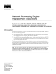
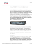
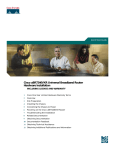
1
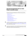
Cisco − Determining RF or Configuration Issues On the CMT
Cisco − Determining RF or Configuration Issues On the CMTS
Table of Contents
Determining RF or Configuration Issues On the CMTS................................................................................1
Introduction.............................................................................................................................................1
Before You Begin...................................................................................................................................1
Conventions......................................................................................................................................1
Prerequisites.....................................................................................................................................1
Components Used.............................................................................................................................2
RF Plant Troubleshooting Rules.............................................................................................................2
Cable Show Commands for RF Problems..............................................................................................3
DOCSIS Cable Upstream RF Specifications...................................................................................4
DOCSIS Cable Downstream RF Specifications..............................................................................5
Notes for Tables...............................................................................................................................6
Checking the Downstream...............................................................................................................6
Checking the Upstream....................................................................................................................8
Using the Flap List for Diagnosing RF Problems.................................................................................15
Related Information..............................................................................................................................16
i
Determining RF or Configuration Issues On the
CMTS
Introduction
Before You Begin
Conventions
Prerequisites
Components Used
RF Plant Troubleshooting Rules
Cable Show Commands for RF Problems
DOCSIS Cable Upstream RF Specifications
DOCSIS Cable Downstream RF Specifications
Notes for Tables
Checking the Downstream
Checking the Upstream
Using the Flap List for Diagnosing RF Problems
Related Information
Introduction
This document describes the troubleshooting steps to determine whether a cable network problem is in a cable
router or an RF plant issue. The majority of RF plant issues are diagnosed by low upstream Signal to Noise
Ratio (SNR) level, hence heavy emphasis is placed on examining this value. Initially the document states
some simple rules to follow, together with an explanation of how the upstream SNR level is calculated. It then
illustrates the major configuration parameters and commands to use to verify the downstream and upstream
channels. It finishes with an explanation of the flap list command to further diagnose RF issues.
Using a spectrum analyzer for troubleshooting the RF plant is beyond the scope of this document. If the SNR
level or other analysis points towards an RF plant issue and you wish to troubleshoot this area further using a
spectrum analyzer, then refer to the Connecting and Configuring the Cable Headend in the related information
section.
All uBR7100, uBR7200, and uBR10000 models, and NPE cards with different Cable Cisco IOS® Software
versions follow the same principle in troubleshooting whether this is an RF issue or not. The only difference
may be some command syntax changes and performance capabilities, and the fact that the uBR7100 has an
integrated upconverter.
Before You Begin
Conventions
For more information on document conventions, see the Cisco Technical Tips Conventions.
Prerequisites
This document assumes that the reader has access to a Cisco uBR9xx or CVA120 series cable modem to assist
in their troubleshooting.
Cisco − Determining RF or Configuration Issues On the CMTS
Components Used
The information in this document is based on Cisco hardware uBR7246 VXR (NPE300) processor (revision
C) and Cisco IOS Software (UBR7200−K1P−M), Version 12.1(9)EC and a CVA122 Cisco IOS Software
12.2(2)XA.
RF Plant Troubleshooting Rules
• The RF plant can be thought of as a MAC layer two equivalent. Usually, if there is a problem with the
RF plant, then layer two connectivity will not be established. If the show cable modem command
indicates that the online state has progressed past init(rc) status, then this is an indication that layer
two connectivity has been established and usually does not indicate an RF problem. However it is
possible for the Cable Modem to go past init(rc) and even as far as init(i) but still have RF issues. In
this case using a narrower upstream channel may prove the problem is RF−related. See the cable
upstream 0 channel−width xxx command.
• Before installing a live network always verify the cable router configurations in a controlled
environment such as a laboratory where the RF plant characteristics are known. Thus when installing
in a live network the characteristics of the router configurations are known and can be eliminated as a
problem source. A good RF design is imperative to make this work. Documents that should be read
before putting the cable network into production use are Connecting and Configuring the Cable
Headend and RF Specifications.
• The downstream direction is a broadcast domain. a problem that is affecting a large number of cable
modems (or all cable modems), it is likely to be in the downstream plant.
• The upstream direction is based on individual circuits per cable modem. Most cable network
problems are in the upstream direction. A problem affecting individual or small groups of cable
modems may be in the upstream direction. However, loose connections, downstream ingress, and
drop problems could affect the downstream signal to an individual cable modem. Likewise, a problem
with an individual downstream laser, optical link, node, or coax plant beyond the node could affect
just a small number of modems.
• Many upstream cable modem problems are caused by low signal to noise ratio (SNR). However, note
that the Broadcom chip SNR estimate could indicate apparent normal operation, yet impulse noise (or
a similar impairment not indicated by the SNR) may be the real culprit. The show controller cable
x/x and show cable modem detail commands interrogate the Broadcom 3137 chip on the uBR72xx
line cards that computes the upstream SNR value . Note that carrier−to−noise ratio, or CNR, is a more
appropriate term, since SNR is really a post−detection baseband measurement. Below is an
explanation of how the upstream is calculated.
• The settings on an external upconverter used when having uBR7200 and uBR10000 need to be
properly set. Remember that GI Upconverters are configured 1.75 MHz less than the Center
Frequency according to the NTSC table. For an explanation of why this is so, please read Cable Radio
Frequency (RF) FAQs.
• Different MC cards have different output power on the downstream port. For this reason, for some
cards it is necessary to add padding (external attenuation). Make sure that you follow the
specifications on how much padding to add with regards to the specific linecard used. MC11 and
MC16B cards give an output power of 32 dBmV and they do not need padding. However, all the
other MCxx cards give an output power of 42 dBmV and therefore need 10dB padding. For more
information about the cards specifications read Features, Differences, and IOS Support for Cable
Modem Cards for Cisco uBR7200 Series.
The SNR estimating process uses only packets that are free from uncorrectable forward error corrections
(FEC) errors and is averaged over 10,000 received symbols. If the packet is damaged it is not counted, and the
upstream SNR estimate can read artificially high. The upstream SNR estimate does not take into account the
real world of burst noise, impulse or intermittent noise that is common in CATV upstream networks.
Cisco − Determining RF or Configuration Issues On the CMTS
Comparing the Broadcom's upstream SNR estimate to what one would measure with a spectrum analyzer will
often yield quite different results. The Broadcom chips upstream SNR estimating process is most reliable in
the 25 to 32 dB range. If the upstream SNR estimate reaches 35 dB or greater consider the result to be
unreliable and gain a true upstream CNR measurement using a spectrum analyzer.
The optimal period to collect the 10,000 symbols is 10−20 msec of 100% utilization upstream for a 3.2 or 1.6
MHz channel width. It would not be usual to have this quantity of traffic being passed and at the same time to
be experiencing a low upstream SNR. The lower the upstream SNR the greater the degradation of traffic
passed. This degradation causes the Broadcom chip to take too long to collect the 10,000 symbols and for the
resulting upstream SNR estimate to be inaccurate. If the upstream SNR estimate falls below 25 dB consider it
to be unreliable. At this low upstream SNR level the system is experiencing lots of errors and too little traffic.
Expect a lot of flap list entries and SID connectivity numbers to be low. The command show cable hop
should indicate lots of FEC correctable and uncorrectable errors.
After mentioning the above limitations however, if the upstream SNR level is between 25 and 32 dB as shown
by show controller cable x/x , use this command to determine whether there is an apparent RF issue.
The upstream CNR estimate is generally 3−4dB lower than the upstream SNR estimate. In a typical cable
plant you should expect to see an upstream SNR of 32−33dB and an upstream CNR of 28−29dB.
Cable Show Commands for RF Problems
The following show commands are used on the CMTS to help diagnose RF issues:
• show controllers cable x/x downstream
• show controllers cable x/x upstream
• show cable modem detail
• show interface cable x/x upstream y
• show cable hop
• ping docsis
• show cable flap−list
The following show commands are used on the CM to help diagnose RF issues:
• show controllers cable−modem 0 | include snr
For reference also refer to the Understanding Show Command Responses document.
The show controllers cable x/x downstream and show controllers cable x/x upstream commands can be
used to show the layer two status of the cable card on the CMTS when diagnosing suspected RF problems.
Use these commands to check the frequency settings being used and the upstream SNR value. The show
controllers cable x/x upstream command should be entered several times to see if the SNR value fluctuates
rapidly. Even with good upstream SNR values a very rapid fluctuation also means RF problems.
Use the show interface cable x/x upstream y command to check for noise within the RF plant. If the
uncorrectable errors, noise and microreflection counters are high and increasing quickly, then this typically
indicates there is noise present within the RF plant. You can also use the ping docsis command to verify the
layer two connectivity to the cable modem.
Use these commands to check:
• The configuration parameters
Cisco − Determining RF or Configuration Issues On the CMTS
• The downstream and upstream frequencies used
• The noise measurements in dB. Make certain that they are correct and within the allowed limits. A
table of the noise limits is included below:
DOCSIS Cable Upstream RF Specifications
Note: *n indicates additional information below.
Specifications
UPSTREAM
DOCSIS Specifications *1 Minimum Settings *2
System/Channel
Frequency range
Transit delay from
the most distant CM
to the nearest CM or
CMTS.
Carrier to noise
ratio
Carrier to ingress
power ratio
Carrier to
interference ratio
Carrier hum
modulation
Burst noise
Amplitude ripple
Group delay ripple
Micro reflections
(single echo)
5 to 42 MHz (North
America) 5 to 65 MHz
(Europe)
< 0.800 µsec
< 0.800 µsec
25 dB
25 dB
> 25 dB
> 25 dB
> 25 dB (QPSK) *4
> 21 dB (QPSK) *4
> 25 dB (16 QAM) *4
> 24 dB (16 QAM) *4
< −23 dBc *6 (7%)
< −23 dBc (7%)
Not longer than 10 µsec at a
Not longer than 10 µsec
1 kHz average rate for most
at a 1 kHz average rate
cases.
for most cases.
0.5 dB/MHz
0.5 dB/MHz
200 ns/MHz
−10 dBc @ < 0.5 µsec
200 Ns/MHz
−20 dBc @ < 1.0 µsec
30 dBc @ 1.0 µsec
Seasonal/diurnal
signal level
variation
Digital Signal Levels
From cable modem
(upstream)
5 to 42 MHz (North
America) 5 to 65 MHz
(Europe)
−10 dBc @ < 0.5 µsec
−20 dBc @ < 1.0 µsec
30 dBc @ 1.0 µsec
Not greater that 8 dB min to Not greater than 8 dB
max.
min to max.
+8 to +58 dBmV (QPSK)
+8 to +58 dBmV
(QPSK)
+8 to +55 dBmV (16 QAM)
Cisco − Determining RF or Configuration Issues On the CMTS
+8 to +55 dBmV (16
QAM)
Input amplitude to
modem card
(upstream)
Signal as relative to
adjacent video
signal
−16 to +26 dBmV,
depending on symbol rate.
−16 to +26 dBmV,
depending on symbol
rate.
−6 to −10 dBc
−6 to −10 dBc
DOCSIS Cable Downstream RF Specifications
Specification
DOWNSTREAM
System/Channel
RF channel spacing
(bandwidth)
Transit delay *3
Carrier to noise ratio
Carrier−to−interference
ratio for total power
(discrete and broadband
ingress signals).
Composite triple beat
distortion
Carrier to second order
Cross−modulation level
Amplitude ripple
Group delay
DOCSIS Specifications
*1
Minimum Settings
*2
6 MHz
6 MHz
0.800 µsec
0.800 µsec
35 dB
35 dB
> 35 dB
> 35 dB
< −50 dBc *6
< −50 dBc
< −50 dBc
< −50 dBc
< −40 dBc
< −40 dBc
0.5 dB in 6 MHz
0.5 dB in 6 MHz
75 ns in 6 MHz
75 Ns in 6 MHz
−10 dBc @ < 0.5
µsec
−10 dBc @ < 0.5 µsec
Micro reflections bound
for dominant echo
−15 dBc @ < 1.0 µsec
−20 dBc @ < 1.5 µsec
−30 dBc @ >1.5 µsec
−15 dBc @ < 1.0
µsec
−20 dBc @ < 1.5
µsec
−30 dBc @ >1.5
µsec
Carrier hum modulation
Burst noise
< −26 dBc (5%)
Not longer than 25 µsec
at a 10 kHz average rate.
< −26 dBc (5%)
Not longer than 25
µsec at a 10 kHz
average rate.
Cisco − Determining RF or Configuration Issues On the CMTS
Seasonal/diurnal signal
level variation
Signal level slope (50 to
750 MHz)
Maximum analog video
carrier level at the CM
input, inclusive of above
signal level variation.
Minimum analog video
carrier level at the CM
input, inclusive of above
signal level variation.
8 dB
8 dB
16 dB
16 dB
+17 dBmV
+17 dBmV
−5 dBmV
−5 dBmV
−15 to +15 dBmV
−15 to +15 dBmV
−6 to −10 dBc
−6 to −10 dBc
Digital Signal Levels
Input to cable modem
(Level range, one
channel)
Signal as relative to
adjacent video signal
Notes for Tables
*1 −DOCSIS specifications are baseline settings for a DOCSIS−compliant, two−way data−over−cable
system.
*2 − Minimum settings are slightly different than the DOCSIS settings to account for cable system variations
over time and temperature. Using these settings should increase the reliability of DOCSIS−compliant,
two−way data−over−cable systems.
*3 − QPSK = Quadrature Phase−Shift Keying: a method of modulating digital signals onto a radio−frequency
carrier signal using four phase states to code two digital bits.
*4 − These settings are measured relative to the digital carrier. Add 6 or 10 dB, as determined by your
company's policy and derived from the initial cable network setup, relative to the analog video signal.
*5 − QAM = Quadrature Amplitude Modulation: a method of modulating digital signals onto a
radio−frequency carrier signal involving both amplitude and phase coding.
*6 − dBc = decibels relative to carrier.
Note: For a full set of the specifications for the European Standard, please read RF Specifications.
Checking the Downstream
When checking the downstream interface begin by ensuring that the configuration is correct. In most cases
when configuring the downstream cable interface on the CMTS the default values are sufficient. You do not
need to specify individual parameters unless you want to deviate from system defaults. Use the output below
to match the downstream configuration parameters with the matching values seen in the show commands on
the CMTS and the cable modem.
Cisco − Determining RF or Configuration Issues On the CMTS
interface Cable6/1
ip address 192.168.161.1 255.255.255.0 secondary
ip address 10.1.61.1 255.255.255.0
no keepalive
cable insertion−interval 100
cable downstream annex B
cable downstream modulation 64qam
cable downstream interleave−depth 32
cable downstream frequency 405000000
cable upstream 0 frequency 20000000
cable upstream 0 power−level 0
cable upstream 0 channel−width 3200000
no cable upstream 0 shutdown
cable upstream 1 shutdown
cable upstream 2 shutdown
cable upstream 3 shutdown
VXR#show controller cable 6/1 downstream
Cable6/1 Downstream is up
Frequency 405.0000 MHz, Channel Width 6 MHz, 64−QAM, Symbol Rate 5.056941 Msps
FEC ITU−T J.83 Annex B, R/S Interleave I=32, J=4
Downstream channel ID: 3
VXR#
Make sure that the physical CMTS cable connections are not loose or disconnected, and that the cable modem
card is firmly seated in its chassis slot with the installation screws tight. Also check that you have entered the
correct slot and port numbers for the downstream interface that you are checking.
Remember that entering the downstream center frequency on the CMTS is cosmetic only for uBR7200 and
uBR10000. The uBR7100 has an integrated Upconverter. To learn how to set it up read Setting the Integrated
Upconverter.
Entering a shut/no shut command on the downstream interface that you are checking may resolve problems
where the cable modems find a downstream signal but not an upstream signal.
Important: Using a shut/no shut on the downstream interface in a production environment with several
hundred cable modems may cause them to take a long time before coming back online. In non−production
environments such as new cable installations it is safe to do this.
The downstream SNR value needs to be checked at the cable modem where it is received and not at the
CMTS where it is input into the upconverter that is responsible for the signal sent to the cable modem. This
measurement at the cable modem can pose the following problems:
• Most cable installations do not have Cisco cable modems. Even if they do, the console port on the
Cable Modem is by default locked.
• You have to Telnet to the cable modem to measure the received SNR value. If you do not have IP
connectivity to Telnet you will have to manually go to the customer site where the Cisco Cable
Modem is installed in order to connect using the console port. Ensure that the cable modem has a
configuration that allows you access to the console port.
At the cable modem, use the show controllers cable−modem 0 | include snr command below to check the
downstream SNR value received at the cable modem. Verify that the received SNR level is within the
permitted limits of >30 dB for 64 QAM and >35 for 256 QAM.
Router#show controller cable−modem 0 | include snr
snr_estimate 336(TenthdB), ber_estimate 0, lock_threshold 23000
Cisco − Determining RF or Configuration Issues On the CMTS
Router#
Note: This is showing a downstream receive SNR of 33.6 dB at the cable modem. Acceptance levels are >30
dB for 64 QAM and > 35 dB for 256 QAM.
Annex B is the DOCSIS MPEG framing format standard for North America. Annex A is the European
standard supported only when using the Cisco MC16E cable modem card and Cisco CMTS images that
support EuroDOCSIS Annex A operation. Annex A or B framing format is automatically set when
configuring Cisco cable modem cards. The cable modem card's downstream ports and the connected CPEs on
the network must be set to the same MPEG framing format and support either DOCSIS or EuroDOCSIS
operations as appropriate. For more information about the MC16E card, read Cisco uBR−MC16E 8−MHz
Modem Card.
Setting a downstream modulation format of 256−QAM requires approximately a 6 dB higher carrier−to−noise
ratio (CNR) than 64−QAM at the subscriber's cable modem. If your network is marginal or unreliable at
256−QAM, use the 64−QAM format instead.
If a Cable modem is offline one of the first thing to investigate is the RF plant. For more information read the
offline and ranging troubleshooting sections.
Checking the Upstream
On the upstream side many RF problems are indicated by a low SNR level. Note that upstream impulse noise
is the major source of degraded bit error rate performance. The Broadcom SNR estimate generally will not
show the presence of impulse noise.
Later in this section you will be shown how to check the upstream SNR levels.
Begin by checking the upstream interface, ensuring that the configuration is correct. In most cases when
configuring the upstream cable interface on the CMTS the default values are sufficient. You do not need to
specify individual parameters unless you want to deviate from system defaults. Use the diagram below to
match the upstream configuration parameters with the matching values seen in the show commands at the
CMTS:
interface Cable6/1
ip address 192.168.161.1 255.255.255.0 secondary
ip address 10.1.61.1 255.255.255.0
no keepalive
cable insertion−interval 100
cable downstream annex B
cable downstream modulation 64qam
cable downstream interleave−depth 32
cable downstream frequency 405000000
cable upstream 0 frequency 20000000
cable upstream 0 power−level 0
cable upstream 0 channel−width 3200000
no cable upstream 0 shutdown
cable upstream 1 shutdown
cable upstream 2 shutdown
cable upstream 3 shutdown
VXR#show controller cable 6/1 upstream 0
Cable6/1 Upstream 0 is up
Frequency 19.984 MHz, Channel Width 3.200 MHz, QPSK Symbol Rate 2.560 Msps
Spectrum Group is overridden
SNR 35.1180 dB
Nominal Input Power Level 0 dBmV, Tx Timing Offset 2738
Cisco − Determining RF or Configuration Issues On the CMTS
Ranging Backoff automatic (Start 0, End 3)
Ranging Insertion Interval 100 ms
TX Backoff Start 0, TX Backoff End 4
Modulation Profile Group 1
Concatenation is enabled
part_id=0x3137, rev_id=0x03, rev2_id=0xFF
nb_agc_thr=0x0000, NB_agc_nom=0x0000
Range Load Reg Size=0x58
Request Load Reg Size=0x0E
Minislot Size in number of Timebase Ticks is = 8
Minislot Size in Symbols = 128
Bandwidth Requests = 0x335
Piggyback Requests = 0xA
Invalid BW Requests= 0x0
Minislots Requested= 0xA52
Minislots Granted = 0xA52
Minislot Size in Bytes = 32
Map Advance (Dynamic) : 2447 usecs
UCD Count = 46476
DES Ctrl Reg#0 = C000C043, Reg#1 = 0
VXR#
Make sure that the physical CMTS cable connections are not loose or disconnected and that the cable modem
card is firmly seated in its chassis slot with the installation screws tight. Also that you have entered the correct
slot and port numbers for the upstream interface you are checking.
Remember that the upstream channel on the Cisco cable modem is by default shut down and you will need to
issue the no shut command to activate it.
Note: The upstream frequency displayed in the show controllers cable command output might not match the
frequency that you entered when you set the upstream frequency. The Cisco CMTS might select an upstream
frequency close to the frequency you entered that offers better performance. The minimum upstream
frequency step size on the MC16C is 32 kHz. The Cisco CMTS selects the closest frequency available. See
the explanation of the cable upstream 0 frequency command for this.
Note: Some cable systems cannot reliably transport frequencies near the allowed band edges. The wider the
upstream channel (in MHz), the more difficulty you might have. Enter a center frequency between 20 and 38
MHz if you experience problems. The Cisco CMTS will then command the cable modems to use a
downstream frequency within this range. Setting the right upstream frequency is the most important task in
designing the RF network. The upstream operates on the range 5 to 42 MHz. Below 20MHz it is common to
find a lot of interference. Contrary to a lab environment, setting up the upstream in a live network represents
the biggest RF challenge.
Note: Higher symbol rates are more susceptible to RF noise and interference. If you use a symbol rate or
modulation format beyond the capabilities of your HFC network you might experience packet loss or poor
cable modem connectivity. This can be seen in the figure below where a higher CNR is needed to maintain the
same bit error rate (BER) with more complex modulation formats.
Cisco − Determining RF or Configuration Issues On the CMTS
Waterfall curves. More complex modulation formats require a higher CNR (or C/N ratio) in order to maintain
the same BER.
The upstream input power level at the CMTS is normally expected to be 0 dBmV. This power level can be
increased to overcome noise in the RF plant. If the upstream input power level is increased then cable
modems on your HFC network will increase their upstream transmit power level. This increases the
carrier−to−noise ratio (CNR) overcoming the noise on the RF plant. See the explanation of the cable
upstream x power−level y command for this. You should not adjust your input power level by more than 5
dB in a 30−second interval. If you increase the power level by more than 5 dB within 30 seconds cable
modem service on your network will be disrupted. If you decrease the power level by more than 5 dB within
30 seconds cable modems on your network will be forced offline.
Software adjustments of 1 to 3 dB can be used to adjust for minor variations in measurement, or setup and
port−to−port calibration differences. These adjustments can significantly improve cable modem performance,
especially in marginal situations. Larger adjustments should be made in conjunction with spectrum analyzer
support at the headend or distribution hub.
As mentioned earlier, many RF problems are indicated by a low upstream SNR level. If your upstream SNR
level is low try to use a narrower channel width (cable upstream 0 channel−width xxx) for the upstream, for
example, instead of 3.2 Mhz use 200 khz. If the upstream SNR level increases then you have a noise problem.
Use the show controller cable x/x upstream y command to check the upstream SNR level for a particular
cable interface:
VXR#show controller cable 6/1 upstream 0
Cable6/1 Upstream 0 is up
Frequency 19.984 MHz, Channel Width 3.200 MHz, QPSK Symbol Rate 2.560 Msps
Spectrum Group is overridden
SNR 35.1180 dB
!−− Note: Check the Upstream SNR level for an interface here
Nominal Input Power Level 0 dBmV, TX Timing Offset 2738
Ranging Backoff automatic (Start 0, End 3)
Ranging Insertion Interval 100 ms
TX Backoff Start 0, TX Backoff End 4
Modulation Profile Group 1
Concatenation is enabled
part_id=0x3137, rev_id=0x03, rev2_id=0xFF
NB_agc_thr=0x0000, NB_agc_nom=0x0000
Cisco − Determining RF or Configuration Issues On the CMTS
Range Load Reg Size=0x58
Request Load Reg Size=0x0E
Minislot Size in number of Timebase Ticks is = 8
Minislot Size in Symbols = 128
Bandwidth Requests = 0x335
Piggyback Requests = 0xA
Invalid BW Requests= 0x0
Minislots Requested= 0xA52
Minislots Granted = 0xA52
Minislot Size in Bytes = 32
Map Advance (Dynamic) : 2447 usecs
UCD Count = 46476
DES Ctrl Reg#0 = C000C043, Reg#1 = 0
VXR#
You can use the show cable modem detail command to view the SNR estimate for individual cable modems.
(Please see the table below for a further explaination of SID, MAC address, Max CPE, etc.)
VXR#show cable modem detail
Interface
SID MAC address
Cable6/1/U0 1
0001.64ff.e47d
Cable6/1/U0 2
0001.9659.47bf
Cable6/1/U0 3
0004.27ca.0e9b
Cable6/1/U0 4
0020.4086.2704
Cable6/1/U0 5
0002.fdfa.0a63
SID
MAC address
Max CPE
Concatenation
Max CPE
1
1
1
1
1
Concatenation
yes
yes
yes
yes
yes
Service ID
Mac address of the cable interface of the Cable Modems
The maximum number of hosts that are simultaneously
active on the cable modem
Concatenation combines multiple upstream packets into
one packet to reduce packet overhead and overall latency
as well as increase transmission efficiency. Using
concatenation, a DOCSIS compliant Cable Modem makes
only one bandwidth request for multiple packets, as
opposed to making a different bandwidth request for each
individual packet.
Concatenation will only work if a single cable modem
were to have multiple voice calls each running at the
same data rate without Voice Activity Detection (VAD)
packet suppression.
Note: Concatenation may be a problem if VOIP is not
configured correctly.
Rx SNR
Received Upstream SNR level at the CMTS. If the CMTS
is not configured for SNMP reads from the Cable
Modems then the CMTS will return a zero value.
The Signal to Noise Ratio (SNR) is the difference in
amplitude between a baseband signal and the noise in a
portion of the spectrum.
Cisco − Determining RF or Configuration Issues On the CMTS
Rx SNR
33.61
31.21
31.14
32.88
33.61
In practice, a margin of 6dB or more may be required for
reliable operation.
Use the show interface cable x/x upstream y command as shown below to check for noise within the RF
plant. If the uncorrectable errors, noise, and microreflection counters are high and increasing quickly, then this
typically indicates there is noise present within the RF plant. (Please see the table below for a further
information on this output.)
VXR# show interfaces cable 6/1 upstream 0
Cable6/1: Upstream 0 is up
Received 22 broadcasts, 0 multicasts, 247822 unicasts
0 discards, 1 errors, 0 unknown protocol
247844 packets input, 1 uncorrectable
0 noise, 0 microreflections
Total Modems On This Upstream Channel : 1 (1 active)
Default MAC scheduler
Queue[Rng Polls] 0/64, fifo queueing, 0 drops
Queue[Cont Mslots] 0/52, FIFO queueing, 0 drops
Queue[CIR Grants] 0/64, fair queueing, 0 drops
Queue[BE Grants] 0/64, fair queueing, 0 drops
Queue[Grant Shpr]
0/64, calendar queueing, 0 drops
Reserved slot table currently has 0 CBR entries
Req IEs 360815362, Req/Data IEs 0
Init Mtn IEs 3060187, Stn Mtn IEs 244636
Long Grant IEs 7, Short Grant IEs 1609
Avg upstream channel utilization : 0%
Avg percent contention slots : 95%
Avg percent initial ranging slots : 2%
Avg percent minislots lost on late MAPs : 0%
Total channel bw reserved 0 bps
CIR admission control not enforced
Admission requests rejected 0
Current minislot count
: 40084
Flag: 0
Scheduled minislot count : 54974
Flag: 0
VXR#
Received broadcasts
Broadcast packets received through this
upstream interface
multicasts
Multicast packets received through this
upstream interface
Unicasts
Unicast packets received through this
interface
Discards
Errors
Unknown
Packets discarded by this interface
Sum of all errors that prevented upstream
transmission of packets
Packets received that were generated
using a protocol unknown to the Cisco
uBR7246 Noise Upstream packets
corrupted by line noise
Packets input
Packets received through upstream
interface free from errors
Corrected
Error packets received through upstream
interface that were corrected
Cisco − Determining RF or Configuration Issues On the CMTS
Uncorrectable
Error packets received through upstream
interface that could not be corrected
Noise
and Upstream packets corrupted by line
noise
Microreflections
Upstream packets corrupted by
microreflections
Total Modems On This
Upstream Channel
Number of cable modems currently
sharing this upstream channel. This field
also shows how many of these modems
are active.
Rng Polls
The MAC scheduler queue showing
number of ranging polls.
Cont Mslots
The MAC scheduler queue showing
number of forced contention request slots
in MAPS
CIR Grants
The MAC scheduler queue showing
number of CIR grants pending
BE Grants
The MAC scheduler queue showing
number of best effort grants pending
Grant Shpr
Reserved slot table
Req IEs
Req/Data lEs
Init Mtn IEs
Stn Mtn IES
Long Grant lEs
ShortGrmg lEs
Avg upstream channel
utilization
Avg percent contention slots
Avg percent initial ranging
slots
The MAC scheduler queue showing
number of grants buffered for traffic
shaping
At time command issued MAO scheduler
had admitted 2 CBR slots in the reserved
slot table.
Running counter of request lEs sent in
MAPS
Counter of request/data lEs sent in MAPS
Counter of Initial Maintenance lEs
Number of station maintenance (ranging
poll) lEs
Number of long grant lEs
Number of short grantlEs
Average percent of the upstream channel
bandwidth being used
Average percent of slots available for
modems to request bandwidth via
contention mechanisms. Also indicates
the amount of unused capacity in the
network.
Average percent of slots in initial ranging
state
Cisco − Determining RF or Configuration Issues On the CMTS
Avg percent minislots lost on
late Maps
Total channel bw reserved
Average percent of slots lost because a
MAP interrupt was too late
Total amount of bandwidth reserved by
all modems sharing this upstream channel
that require bandwidth reservation. The
Class of Service for these modems
specifies some non−zero value for the
guaranteed upstream rate. When one of
these modems is admitted on the
upstream, this field value is incremented
by this guaranteed−upstream rate value.
Note: Check the noise and microreflection counters. They should be very low values and, in a normal cable
plant, increment slowly. If they are at a high value and increment quickly it typically indicates a problem with
the RF plant.
Note: Check for uncorrectable errors. These typically indicate a problem with noise within the RF plant.
Check the received upstream SNR level.
Use the show cable hop command to check the correctable and uncorrectable FEC error counts for a specific
interface or upstream port. Consider that uncorrectable FEC errors result in dropped packets. Correctable FEC
errors are right before uncorrectable FEC errors, and should be considered a warning sign of uncorrectable
errors yet to come. The information from show cable hop describes the frequency hop status of an upstream
port. (Please see the table below for a further information on this output.)
VXR#show cable hop cable 6/1 upstream 0
Upstream
Port
Poll Missed Min
Missed Hop
Hop
Port
Status
Rate Poll
Poll
Poll
Thres Period
(ms) Count Sample Pcnt
Pcnt (sec)
Cable6/1/U0 20.000 MHz 1000 * * * set to fixed frequency * * *
VXR#
Upstream
Port
Port Status
Poll Rate
Missed Poll
Count
Min Poll
Sample
Missed
PollPcnt
Hop Thres
Pcnt
Hop Period
The upstream port for this information line
Lists the status of the port. Valid states are down if
frequency is unassigned or administrative down if the port is
shut down. If the port is up, this column shows the center
frequency of the channel.
The rate that station maintenance polls are generated (in
milliseconds).
The number of missing polls
The number of polls in the sample.
The ratio of missing polls to the number of polls, expressed
as a percentage
The level that the missed poll percentage must exceed to
trigger a frequency hop, expressed as a percentage.
Cisco − Determining RF or Configuration Issues On the CMTS
Corr
FEC
Errors
10
Uncorr
FEC
Errors
1
The maximum rate that frequency hopping will occur (in
seconds)
Corr FEC
Errors
The number of correctable forward error corrections (FEC)
errors on this upstream port. FECs measure noise.
Uncorr FEC
Errors
The number of uncorrectable FEC errors on this upstream
port
You can use the show cable hop command to check for correctable and uncorrectable FEC errors on a
particular interface. Counters should have a low value. High or rapidly increasing uncorrectable errors
typically indicates a problem with noise within the RF plant. If this is the case, check the received upstream
SNR level.
Finally use the ping docsis command to verify the layer two connectivity to the cable modem:
VXR#ping docsis ?
A.B.C.D Modem IP address
H.H.H
Modem MAC address
Note: Use this command to ping either the modem IP or MAC address:
VXR#ping docsis 10.1.61.3
Queueing 5 MAC−layer station maintenance intervals, timeout is 25 msec:
!!!!!
Success rate is 100 percent (5/5)
VXR#
Using the Flap List for Diagnosing RF Problems
One of the most powerful tools on the CMTS for diagnosing RF problems on cable networks is the show
cable flap−list command. To assist in locating cable plant problems the CMTS maintains a database of
flapping cable modems . In this document we highlight the most important things that are used by this feature
from a practical point of view. For very detailed information about the flap list feature, please read Flap−List
Troubleshooting for the Cisco Cable Modem Termination System, which contains all you want to know about
this feature.
Below is a sample output from the show cable flap−list command. Note that an asterisk appears in the power
adjustment field when an unstable return path for a particular modem has been detected and a power
adjustment has been made. An exclamation point appears when so many power adjustments have been made
that the modem has reached its maximum power transmit level and cannot increase it any further. Both of
these indicate a problem in the RF plant.
VXR#sh cable flap−list
MAC Address
Upstream
0001.64ff.e47d Cable6/1/U0
0001.9659.47bf Cable6/1/U0
0004.27ca.0e9b Cable6/1/U0
0020.4086.2704 Cable6/1/U0
0002.fdfa.0a63 Cable6/1/U0
Ins
0
0
0
0
0
Hit
20000
30687
28659
28637
28648
Miss
1
3
0
4
5
CRC
0
0
0
0
0
*
P−Adj
*30504
*34350
!2519
2468
2453
Means that a power adjustment has been made
! Indicates that a cable modem increased its power level to the maximum
level. For Cisco cable modems that equals 61 dBmV.
Cisco − Determining RF or Configuration Issues On the CMTS
Flap
30504
34350
2519
2468
2453
Time
Oct 25
Oct 25
Oct 23
Oct 23
Oct 23
08:35:32
08:35:34
16:21:18
16:20:47
16:21:20
The flap list is an event detector, and there are three situations that causes an event to be counted. Below is a
description of these events that cause a cable modem to be entered into the flap list.
1. REINSERTIONS
First, we might see flaps along with insertions if a modem has a registration problem and keeps trying
to quickly reregister over and over. The P−Adj column may be low. When the time between two
initial maintenance re−registrations by the CM is less than 180 seconds, you'll get "flaps" along with
"insertions." Therefore, the flap detector will count it. This default value of 180 seconds can be
changed if desired. Reinsertions also help to identify potential problems in the downstream because
improperly provisioned cable modems tend to try to reestablish a link repeatedly:
VXR(config)#cable flap−list insertion−time ?
<60−86400> Insertion time interval in seconds
2. HIT/MISSES
Secondly, the flap detector will count a flap when we see a "miss" followed by a "hit". Event
detection is counted in the "Flap" column only. These polls are hello packets that are sent every 30
seconds. If we get a "miss" followed by a "miss" the polls will be sent every second for 16 seconds
vigorously attempting to get a response. If we get a "hit" before the 16 seconds are up, you'll get a flap
but if you don't get a "hit" for 16 polls, the modem will go off−line in order to begin initial
maintenance all over again. If the modem finally comes back online, you'll get an "insertion" because
the CM inserted itself back into an active state. The flap count is incremented if there are 6
consecutive misses. This default value can be changed if desired. If there are a number of misses then
this typically points to a potential problem in the upstream:
VXR(config)#cable flap miss−threshold ?
<1−12> missing consecutive polling messages
3. POWER ADJUSTMENTS
Finally, the flap detector will show a "flap" in the list when we see power adjustment activity. Event
detection is counted in the P−Adj columns and the "Flap" column. The station maintenance poll
constantly adjusts the cm transmit power, frequency, and timing. Whenever the power adjustment
exceeds 2 dB then the "Flap" and the P−Adj" counter is incremented. This suggests upstream plant
problems. The threshold default value of 2 dB can be changed if desired. If constant power
adjustments are detected, this usually indicates a problem with an amplifier. By looking at the cable
modems in front and behind various amplifiers, you can find the source of failure:
VXR(config)#cable flap power−adjust ?
threshold Power adjust threshold
Related Information
• Understanding System Operations
• Troubleshooting the Hardware Installation
• HUKK Online RF Training
• Connecting and Configuring the Cable Headend
• Flap−List Troubleshooting for the Cisco Cable Modem Termination System
• RF Specifications
• Cable Radio Frequency (RF) FAQs
• Understanding Show Command Responses
Cisco − Determining RF or Configuration Issues On the CMTS
• Features, Differences, and IOS Support for Cable Modem Cards for Cisco uBR7200 Series
• Technical Support − Cisco Systems
All contents are Copyright © 1992−2003 Cisco Systems, Inc. All rights reserved. Important Notices and Privacy Statement.
Cisco − Determining RF or Configuration Issues On the CMTS