1
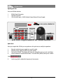
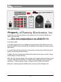
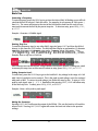
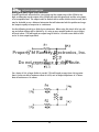
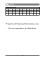
USER GUIDE
JANUARY, 2005
Rev. 1.3
Property of Ramsey Electronics, Inc.
Do not reproduce or distribute.
SG560 SIGNAL GENERATOR
Copyright Ramsey Electronics, Inc. 2005, All rights reserved
1
TABLE OF CONTENTS
Introduction
• Opening the Box..................................................................................................................4
• Quick Start .............................................................................................................................4
• Introduction...........................................................................................................................5
• Front Panel Overview .........................................................................................................6
Basic Use
• Generating a Frequency.....................................................................................................8
• Setting Generator Level .....................................................................................................8
• Muting the Generator.........................................................................................................8
• Setting Generator Offset....................................................................................................9
• Selecting a Waveform (Shape)........................................................................................9
• Saving and Recalling Memories ................................................................................... 10
• Adjusting Display Contrast............................................................................................. 10
Detailed information
• Examples of Waveforms and Offsets .......................................................................... 12
• Using the SG560 Differential Outputs........................................................................ 13
• Performing Manual Frequency Sweeps ..................................................................... 13
• Setting Meter Output Impedance................................................................................ 14
• Filter Testing ....................................................................................................................... 14
• Signal Descriptions........................................................................................................... 15
• Dealing with Small Signal Levels and Noise ...............................................................0
Property of Ramsey Electronics, Inc.
Do not reproduce or distribute.
Appendix
CTS Tone Frequency List................................................................................................. 20
Specifications ..................................................................................................................... 22
Warranty .............................................................................................................................. 23
•
•
•
2
Property of Ramsey Electronics, Inc.
INTRODUCTION
Do not reproduce or distribute.
3
INTRODUCTION
Opening the Box
Your new SG560 includes:
1
1
1
SG560 Signal Generator
Operator’s manual
120/240 VAC Input, 12VDC/500mA Output External Power Supply
SG560 AUDIO GENERATOR
SHIFT
DATA
1
2
3
a
b
c
MHz
V
FREQ
Property of Ramsey Electronics, Inc.
POWER
4
5
6
e
f
kHz
mV
LEVEL
d
7
8
9
Hz
OFFSET
0
SHIFT
RCL
STO
SHAPE
.
0-5MHZ
TRUE-DC
(-)
(+)
Do not reproduce or distribute.
mute
Quick Start
Once you unpack the SG560 you can perform a this quick test to verify the operation.
1.
2.
3.
4.
Plug the included power supply into your AC outlet.
Plug the power supply into the rear of the SG560.
Turn on the SG560. The display will show the default Frequency, Level, and Offset.
Use the buttons to check their function. Press the FREQ button, then press 100kHz.
5.
Use the jog dial to adjust the frequency in increments.
4
INTRODUCTION
Introduction
The SG560 is more than an audio generator. It is also a signal generator that produces AC
signals with DC coupling at the output jacks like a digital signal generator. The versatility of
the SG560 will allow you to recreate many basic signals used in testing situations.
The SG560 allows you to generate square waves, sine waves, and triangle waves of any frequency from 0Hz to 5MHz in 0.1MHz steps. The frequency accuracy is tied to a crystal reference with an accuracy of ±20ppm over its full temperature range.
You can also step the frequency at any arbitrary increment. For example a step of 37.5kHz
can be entered and the dial or shift arrows can be used to step the frequency up and down
by this amount.
The SG560 uses a robust output stage for the final driver. It is derived from DSL modems and
is essentially a high power opamp. The opamp is capable of delivering 2.5W to a load before
going into protective shutdown. It is being used in a differential fashion which means that
any common mode noise is cancelled on the output. The output voltage can swing from 10V
peak to peak with a 5V DC offset without clipping. For a negative DC voltage output, swap
the polarity of the cables attached to the jacks.
Property of Ramsey Electronics, Inc.
Do not reproduce or distribute.
The SG560 allows digital entry of the output level with a resolution of 10mV. For example if
you enter 5.55V, the SG560 will generate a 5.55V peak to peak waveform at the jacks. The
SG560 has an additional option which allows the user to set the output impedance. It can be
50 ohms, 25 ohms, or or 0 ohms impedance at the output jacks. With a 50 ohm output impedance a 50 ohm load will drop the output signal level by ½ of the value entered. With 0
ohms a 50 ohm load will not drop the level at all. The 25 ohm output setting can help when
driving a capacitive load; the 0 ohm setting should never be used with this type of load.
A DC offset may be entered; this is added (or subtracted if the jack connections are reversed)
to the AC signal. Rather than the output AC waveform being centered on 0VDC, a set DC voltage can be added to your signal. This allows the performance of tests that are not possible
with a basic audio signal generator. For example, a small circuit can be powered by the DC
offset as long as it requires less than 2.5W of power, and AC signals can be used to check for
noise or EMI immunity. The DC offset can also be used to recreate digital signals in the
square wave mode. For example, to create TTL square waves, enter 5V for the level, and 2.5V
for the offset. This will create the 5V (digital ‘1’) and the 0V (digital ‘0’) levels needed for testing and clocking digital circuits. With a signal range of up to 10V peak to peak and 5V of offset, even old 4000 series CMOS signal levels can be recreated! While this logic family is not in
wide use, it may be useful for testing older circuits.Both the level and offset fields can be
stepped in arbitrary amounts and have a monotonic resolution of 10mV.
Additionally the SG560 contains 6 non-volatile memories which save the full system settings:
frequency, level, shape, and offset. This allows you to frequency hop or use the memories to
“script” repair, testing, and alignment procedures. The SG560 can be run from a broad spectrum of power sources; this allows for portable battery operation if desired, using the proper
precautions.
5
INTRODUCTION
A
SHIFT
C
DATA
1
2
3
a
b
c
MHz
V
FREQ
4
5
6
B
e
f
kHz
mV
LEVEL
d
POWER
7
8
9
Hz
OFFSET
.
0
SHIFT
RCL
STO
SHAP E
mute
SG560 AUDIO GENERATOR
D
E
0-5MHZ
TRUE-DC
(- )
(+)
Front Panel Overview
Property of Ramsey Electronics, Inc.
A: The display area.
The first line: F: for frequency, shape as a two-character icon, and a letter to indicate last recalled or saved memory.
Do not reproduce or distribute.
The second line: L: for level in volts peak to peak, O: For offset in volts DC.
B: The power switch.
C: The field selection buttons. Press [FREQ] to go to the frequency field, [LEVEL] to go to the
level field, [OFFSET] to go to the offset field, and [SHAPE] to select shape and return to the last
field selected.
D: Jog dial. Turning this will increment or decrement the currently selected field by the preset
step size. Set the step size before turning.
E: Outputs. These are standard-spaced banana jack outputs for test cables or probes, banana
to BNC adapters, or jumper wire sets.
DATA: This is the data entry keypad. The red portions of the buttons indicate what type of data
is entered during alternate selections. For example, when recalling memories, a-f are active
rather than 1-6. When selecting a shape, 7-9 represent SINE, SQUARE, and TRIANGLE.
Shift mode is activated when the [SHIFT] button is pressed and the SHIFT light is ON.
6
Property of Ramsey Electronics, Inc.
BASIC USE
Do not reproduce
or distribute.
7
BASIC USE
Basic Use
Generating a Frequency:
To enter frequency, press the FREQ key to get into the desired field. A blinking cursor will indicate that the field is selected. Enter the value. For example, for a frequency of 1kHz, press 1,
then kHz. The cursor will return to the start of the field and the knob can be used to increment and decrement the field by the preset step size. To abort an entry, press FREQ, LEVEL,
or OFFSET.
Example: Generate a 2.34MHz signal.
Entering Step Size:
To enter the frequency step (or any other field’s step size) press SHIFT and then the field of
interest, in this case the FREQ button. The field will then display an exclamation (!) character
to indicate that you are in increment entry mode. For a step size of 1kHz, enter 1, kHz.
Property of Ramsey Electronics, Inc.
Example: Enter a step size of 345.2Hz.
Do not reproduce or distribute.
Once entered, the dial will step the current selected field by this amount. If settings are saved
to memory the step sizes are also saved.To abort an entry, press FREQ, LEVEL, or OFFSET.
Setting Generator Level:
To enter level, press the LEVEL key to go to the Level field. Any voltage in the range of 0-10V
with 10mV of resolution can be entered. This is the peak to peak voltage, not to be confused
with peak or RMS. To convert to peak voltage, just divide the entry by two. To enter a 5.25V
peak to peak signal, enter 5, ., 2, 5, V. Remember that pressing SHIFT, LEVEL will allow entry
of the level step size. To abort, press FREQ, LEVEL, or OFFSET.
Example: Enter a 0.5V peak to peak signal.
Muting the Generator:
Pressing SHIFT, MUTE will mute the output of the SG560. This sets the level to 0.0V and the
offset to 0.0V. Pressing SHIFT, MUTE again will restore the level and offset to the previous
settings.
8
BASIC USE
Setting Generator Offset:
To enter a DC offset, press the OFFSET key, then any voltage in the range of 0-5V with 10mV
of resolution. The offset is a DC component added to the AC signal. With the offset at zero
volts the AC component is centered around zero and the average voltage is zero volts. When
a DC offset is entered it is added to the waveform, moving the center up (or down) to the
level desired. Remember that SHIFT, OFFSET will enter the offset step size. If a negative DC
offset is desired, simply switch the cables on the output jacks, positive to negative and negative to positive.
For example, TTL (Transistor Transistor Logic) circuits require a 0V to 5V square wave. With a
0V offset the SG560 will generate a –2.5V to +2.5V square wave (average is 0 volts). To get
the square wave to 0 to 5V we must add 2.5V to the AC waveform. In this case, enter an offset of 2.5V. To enter this value, press OFFSET, 2, ., 5, V.
PropertyFig.of
Ramsey Electronics,
Inc.
Fig. B
A
+1.0V
Do not reproduce or distribute.
+0.0V
-1.0V
To further illustrate the uses of DC offset, look at the waveforms above. Fig. A shows a 2V
peak to peak sinewave with 0V of offset. Fig. B shows the same sinewave with 0.3V of offset
applied. 0.3VDC is added to all portions of the wave, both the peaks and the average.
Selecting a Waveform (Shape):
You have a choice of three waveforms on the SG560: Sine, Square, and Triangle. To access
and select any one of these waveforms, use the SHAPE key. Simply press SHAPE and the cursor will highlight in front of the waveform symbol on the first line of the display. Then press
the 7 (Sine), 8 (Square), or 9 (Triangle) key to select the desired waveform. The upper line of
the display will use a graphic representation of the waveform to indicate which is currently
selected.
9
BASIC USE
Saving and Recalling Memories:
To save a memory, set up the SG560 into the desired frequency, level, offset and wave shape.
Press SHIFT, STO and the memory location a through f. These settings are stored in nonvolatile FLASH memory for recall and will be saved whether or not power is applied to the
unit. Be careful; saving a memory will automatically overwrite whatever was previously in that
memory location without prompting to be sure you want to overwrite!
Example: Save a setup to memory location b
To recall a memory, press RCL and then any location from a-f and all characteristics of the
saved waveform will be loaded and activated. The current selected memory location is shown
as a character in the upper right of the display.
Property of Ramsey Electronics, Inc.
As a special feature, memory location a is automatically recalled upon startup of the SG560.
This can be set to whatever state is preferred for power up. Setting memory location a to 0Hz,
0 level, and 0 offset simulates a mute condition, or the SG560 can be set up for the user’s
most common test setup.
Do not reproduce or distribute.
Adjusting Display Contrast
Display contrast settings are not saved when the unit is powered down, but can be adjusted
by pressing SHIFT, then the MHz and kHz buttons to increase or decrease contrast.
or
10
Property of Ramsey Electronics, Inc.
DETAILED INFORMATION
Do not reproduce or distribute.
11
DETAILED INFORMATION
Examples of Waveforms and Offsets
Example of 2V peak to peak with 0V offset and 0.3V offset.
+1.3V
+1.0V
+0.3V
+0.0V
-0.7V
-1.0V
Example of noise test with 0.4V peak to peak and 5V of offset to power a circuit.
Property of Ramsey Electronics, Inc.
+5.2V
+5V
•
+0.2V
+0.0V
-0.2V
-
Do not reproduce or distribute.
Example of square wave with 5V peak to peak and 2.5V of offset to recreate a TTL level waveform.
+2.5V
+5.0V
+0.0V
+2.5V
-2.5V
0.0V
12
DETAILED INFORMATION
Using the SG560 Differential Outputs
Since the SG560 has a differential output, the (+) jack is 180 degrees out of phase with the
(-) jack. If the offset is at 5V the (-) jack has -2.5V of offset and the (+) jack has +2.5V in reference to the internal common point. This gives the combined total of 5V between the jacks.
If there were 100uV of noise on both the (+) and (-) terminals in reference to the internal reference, it would be common-mode noise and wouldn’t be seen on the jacks. The differential
output helps to reduce any noise that a power supply or other interference may introduce into
test situations.
To use this signal generator, tie the (-) jack to ground and the (+) jack to the circuit’s signal
input. This will allow for positive offsets as the display shows. If negative offsets are needed,
simply swap the (+) and (-) jacks. In this case the (+) would be connected to ground, and
the (-) the circuit input.
Performing Manual Frequency Sweeps
For testing of filters and circuit performance, it may be desirable to step the frequency and
compare the input voltage to output voltage of the circuit under test to check its frequency
response. The SG560 is capable of sweeping in linear steps using the keypad or dial. Typically
the circuit setup would be as follows:
Property of Ramsey Electronics, Inc.
Do not reproduce or distribute.
(+)
+
+
IN
-
+
( -)
DMM
-
TEST
CIRCUIT
SG560
OUT
-
Determine the frequency range to be tested. For example, for testing a 20kHz low pass filter,
1kHz through 100kHz would be adequate.
Set the signal generator to 0Hz by entering FREQ, 0, Hz, and then enter a level of 1V peak to
peak by entering LEVEL, 1, V. Make sure the offset is at zero volts by entering OFFSET, 0, V
and the waveform set to Sine SHAPE, ~. Next enter a reasonable step size for the frequency.
For our example we will start at 20 points. 5kHz steps are needed to reach 100kHz. To enter,
press SHIFT, FREQ, 5, kHz.
Now use the dial to step up in 5kHz steps; the sequence would be 5,10,15… 100K. For each
step make note of the meter reading and it would then be possible to enter the values into an
Excel spreadsheet and plot the result, for example.
It is preferable to use a good auto-ranging multimeter for these tests as it will save changing
settings when the filter’s signal output amplitude decreases.
13
DETAILED INFORMATION
Setting Meter Output Impedance
The default output impedance of the SG560 is 50 ohms, but it is possible to change this setting through the use of internal jumpers. The alternate settings are 0 ohms, and 25 ohms output impedance.
A 0 ohm impedance simply means that the output of the SG560 would be coming directly
from a powerful opamp inside the SG560. With the unit set for 0 ohms output impedance
there are no protection resistors between the jacks and the opamp. The opamp is robust but
cannot handle heavy loads that may pull more than 2.5W without the potential for permanent
damage. A direct short will cause the part to shut down. It can recover from this, but a high
voltage present on the output pins may damage it permanently. The part is expensive and
not easy to replace as it is surface mount with a soldered thermal tab underneath. Therefore
extreme caution should be used when setting the SG560 up for 0 ohms output impedance.
Also, with a 0 ohm output impedance no resistors are in series the opamp and it is possible
for the opamp to become unstable (meaning self-oscillate) with a capacitive load of more
than 50pF across the leads. This can lead to unusually heavy current draws which can overheat the output part over a period of time. An overheated part will simply shut down, then
turn back on once it has cooled.
Property of Ramsey Electronics, Inc.
Jumpers J8 and J7 bypass the large 24.9 ohm surface mount resistors. By adding jumpers
across these headers, you effectively short out the resistors. One jumper will give you an output impedance of 25 ohms, and two will be 0 ohms. The default is to have no jumpers and a
50 ohm output impedance.
Do not reproduce or distribute.
By running in 0 ohm configuration, you are able to have confidence in that the front panel
setting of the SG560 is the same right at the jacks no matter what the load is. Normally with a
known output impedance from a signal generator that impedance must be taken into account
as a series resistor in a circuit under test. If the circuit has a 50 ohm input impedance the output of the SG560 divided in half. For example, with the SG560 output impedance on the 50
ohm setting and the output set to 1V peak to peak, when testing a circuit with a 50 ohm load
the effective output of the SG560 is 0.5V peak to peak.
This is found using ohm’s law of V = I x R and the behavior of resistors in series.
Filter Testing
It is interesting to note how a 0 ohm output generator can interact with a complex load such
as a passive filter. When a filter is designed, it typically has a known input and output impedance. With the 0 ohm capability of the SG560 it is possible to put the resistor value of the input impedance in series with the circuit under test to get a good representation of how that
circuit would work in larger design. We are no longer limited by the impedance of the generator.
To illustrate this point, the circuit below represents a filter with a 330 ohm input and output
impedance being driven by the SG560 with a 0 ohm output impedance. The top circuit includes a 330 ohm series resistor to match impedances properly. The lower circuit does not
include this resistor (0 ohms).
14
DETAILED INFORMATION
Signal Descriptions:
TP1 is the SG560 direct output; note the flat line vs. frequency.
TP2 is the correct filter output as expected of a properly input and output matched filter.
TP3 is the frequency response of the lower filter when no matching or an incorrect matching
resistor is used while testing the circuit. Note the difference between TP2 and TP3. Not only
is the level 6 dB higher here in the pass band (since there is no voltage divider), it also has an
additional “bump” that is unexpected from the filter design. This is due to the complex impedance of the filter reacting with the ideal source of the SG560. This is not a desirable response.
TP4 is what would be seen at the output jacks of a generator with a 330 ohm output impedance.
Property of Ramsey Electronics, Inc.
Do not reproduce or distribute.
TP1
TP3
TP4
AMPLITUDE IN DB
TP2
FREQUENCY
15
DETAILED INFORMATION
Dealing with Small Signal Levels and Noise:
If small signal levels are needed for a test setup and the output noise of the SG560 is too
high, an attenuator on the output of the SG560 will scale the signal level and the noise down
to an acceptable level. The output could be limited with a resistor divider circuit as well, but it
may be desirable to use a balanced attenuator that will attenuate both the positive and negative outputs equally to keep noise to a minimum.
Use the following circuit for a divide by ten attenuator. When using this circuit all of you voltage and offset settings will be divided by 10, using an even number makes it easy to adjust
and read values. This will supply an output range of 0.0V to 1.0V with a max offset of 0.5V
and a 10 ohm output impedance.
Property of Ramsey Electronics, Inc.
Do not reproduce or distribute.
For a factor of 100, a larger divider is needed. This will supply a range from 0.0 to greater
than 0.1volts out with a maximum offset of 0.05V, and an output impedance of 10 ohms.
Note all resistors are 1% values.
16
DETAILED INFORMATION
Your Notes:
Property of Ramsey Electronics, Inc.
Do not reproduce or distribute.
17
DETAILED INFORMATION
Your Notes:
Property of Ramsey Electronics, Inc.
Do not reproduce or distribute.
18
Property of Ramsey Electronics, Inc.
APPENDIX
Do not reproduce or distribute.
19
APPENDIX
Standard EIA CTS Tones (Hz)
67.0
79.7
91.5
103.5
118.8
136.5
156.7
179.9
210.7
241.8
71.9
82.5
94.8
107.2
123.0
141.3
162.2
186.2
218.1
250.3
74.4
85.4
97.4
110.9
127.3
146.2
167.9
192.8
225.7
77.0
88.5
100.0
114.8
131.8
151.4
173.8
203.5
233.6
Property of Ramsey Electronics, Inc.
Do not reproduce or distribute.
20
APPENDIX
Property of Ramsey Electronics, Inc.
Do not reproduce or distribute.
21
SPECIFICATIONS
Features:
•Display: 2x16 Character Display
•Memories: 6 Nonvolatile Locations
•Displays: Frequency, Waveshape, Peak to Peak Voltage, Offset Voltage, Memory Selected
•Power Input: 12-16VDC, 500mA, 3.5mm plug
•Waveforms: Sine, Square, Triangle
•Functions: Mute, Customized steps
Generate:
•Frequency: 0.0Hz to 5MHz Sinewave; 0.0Hz to 1MHz Square and Triangle waveforms
•Frequency Steps: 0.1Hz
•Frequency Accuracy: ±15ppm standard
Property
ofpeakRamsey
•Output Level: 0V-10V
to peak, 0.1V steps Electronics, Inc.
•Offset Level: 0V-5V DC offset, 0.1V steps
•Level Accuracy: ±0.5dB 0Hz-1MHz, +0.5dB/-3dB 0Hz-5MHz
Do not reproduce or distribute.
•Offset Accuracy: 1% of display setting
Spurious:
•SINAD: Sine wave 59dB minimum (Signal to Noise + Distortion)
•Distortion: -66dBc below 1 MHz, -56dBc above1 MHz, sine wave.
•Spurious-Free Dynamic Range: Wideband: -60dBc, Narrowband: -78dBc
General:
•Supplied Accessories: 120V to 240V in/12VDC out 500mA switching power supply
•Case color: Mist gray epoxy powder coat
•Dimensions: 9.625” W x 3.625” H x 5.875” D (244.4mm W 92mm H x 149.2 D)
•Weight: 2 lbs
22
Certification
Ramsey Electronics, Inc. certifies that this product meets its published specifications
at the time of manufacture, and that the calibration measurements are traceable to
the United States National Bureau of Standards.
Warranty
Ramsey Electronics, Inc. warrants this product against defects in materials and
workmanship for a period of one year from the original manufacture date. Ramsey
Electronics, Inc., at its option, will repair or replace this product at no cost to the
original owner during the warranty period, provided the product is proved to be
defective.
Warranty Service
To obtain warranty service,
please contact Ramsey
Electronics, Inc. Technical Inc.
Property
of
Ramsey
Electronics,
Support:
RAMSEY ELECTRONICS, INC.
Technical Support
590 Fishers Station Drive
Fishers, NY 14564
585-924-4560
[email protected]
Do not reproduce or distribute.
When returning a unit for repair please include a specific description of the problem
as well as detailed contact information including daytime telephone number, E-Mail
address, and complete return shipping address information.
Limitations
This warranty shall not apply to products that have been improperly cared for,
abused, or used outside the operating specifications of the product. This warranty
shall not apply to products repaired or altered by persons not authorized by Ramsey
Electronics, Inc. This warranty is in lieu of all other warranties, expressed or implied,
and is solely for the use of the original product purchaser.
23
Property of Ramsey Electronics, Inc.
Do not reproduce or distribute.
RAMSEY ELECTRONICS, INC.
590 Fishers Station Drive
Victor, NY 14564
(585) 924-4560
www.ramseytest.com
Copyright Ramsey Electronics, Inc. 2005, All rights reserved
24
SG560
January 2005
Rev. 1.3