1
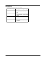
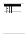
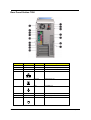
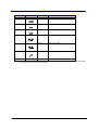
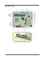
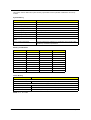
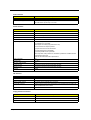
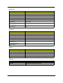
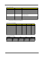
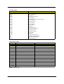
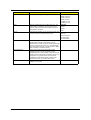
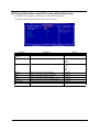
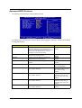
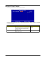
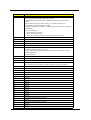
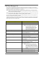
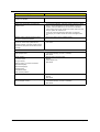
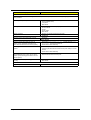
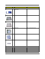
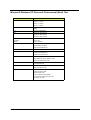
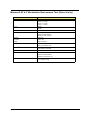
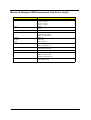
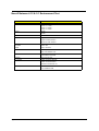
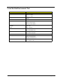
Label
Component
Label
Component
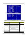
AGP
AGP slot
CNM1
Smart card connector (com2)*
BT1
Battery
CNSW1
IDE cold swap pin
CN2
PS/2 mouse (upper) and keyboard
(lower) ports
DIMM1
Memory slot 1
CN3
Power connector
DIMM2
Memory slot 2
CN4
Network (upper) and USB (lower)
ports
DIMM3
Memory slot 3
CN5
Parallel port (upper) and serial ports
(lower )
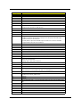
FN1
3-pin fan SYS connector
CN6
Memory Stick Connector
FN2
3-pin fan CPU connector
CN7
IDE 2 connector
FN3
3-pin fan SYS connector
CN8
IDE 1 connector
PCI1
PCI slot 1
CN9
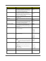
Game/MIDI (upper), line-out (left), line- PCI2
in (middle) and mic-in (right)
connectors
PCI slot 2
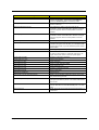
CN10
Power connector (+12V)
PCI3
PCI slot 3
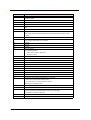
CN14
CD-in connector
U5
CPU socket
CN15
FDD connector
U12
Intel 845 socket
CN16
Intrusion connector
U16
SMSC chipset
CN17
HDD LED connector
U21
Intel ICH2 chipset
BIOS chipset
CN19
Power button
U29
CN20
Front USB connector
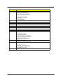
JP1
LAN active LED connector
CN21
Power/Suspend LED connector
JP3
Model Select
CN23
EXT PCI slot
JP14
1-2 Clear CMOS
2-3 Normal**
CNX1
Audio FPIO connector
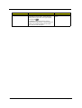
NOTE: Shared connection with serial port 2
NOTE: ** Default Settings
10
Chapter 1