1
User Guide
Signal Processors
GSS 100
Graphic Still Store
68-974-01 Rev. D
02 11
Safety Instructions • English
Warning
This symbol is intended to alert the user of important operating and maintenance (servicing) instructions in the literature provided with the equipment.
Power sources • This equipment should be operated only from the power source indicated on the product. This
equipment is intended to be used with a main power system with a grounded (neutral) conductor. The third
(grounding) pin is a safety feature, do not attempt to bypass or disable it.
This symbol is intended to alert the user of the presence of uninsulated
dangerous voltage within the product’s enclosure that may present a risk of
electric shock.
Power disconnection • To remove power from the equipment safely, remove all power cords from the rear of
the equipment, or the desktop power module (if detachable), or from the power source receptacle (wall plug).
Caution
Read Instructions • Read and understand all safety and operating instructions before using the equipment.
Retain Instructions • The safety instructions should be kept for future reference.
Follow Warnings • Follow all warnings and instructions marked on the equipment or in the user information.
Avoid Attachments • Do not use tools or attachments that are not recommended by the equipment
manufacturer because they may be hazardous.
Consignes de Sécurité • Français
Ce symbole sert à avertir l’utilisateur que la documentation fournie avec le
matériel contient des instructions importantes concernant l’exploitation et la
maintenance (réparation).
Ce symbole sert à avertir l’utilisateur de la présence dans le boîtier
de l’appareil de tensions dangereuses non isolées posant des risques
d’électrocution.
Attention
Lire les instructions• Prendre connaissance de toutes les consignes de sécurité et d’exploitation avant
d’utiliser le matériel.
Conserver les instructions• Ranger les consignes de sécurité afin de pouvoir les consulter à l’avenir.
Respecter les avertissements • Observer tous les avertissements et consignes marqués sur le matériel ou
présentés dans la documentation utilisateur.
Eviter les pièces de fixation • Ne pas utiliser de pièces de fixation ni d’outils non recommandés par le
fabricant du matériel car cela risquerait de poser certains dangers.
Sicherheitsanleitungen • Deutsch
Power cord protection • Power cords should be routed so that they are not likely to be stepped on or pinched
by items placed upon or against them.
Servicing • Refer all servicing to qualified service personnel. There are no user-serviceable parts inside. To prevent
the risk of shock, do not attempt to service this equipment yourself because opening or removing covers may
expose you to dangerous voltage or other hazards.
Slots and openings • If the equipment has slots or holes in the enclosure, these are provided to prevent
overheating of sensitive components inside. These openings must never be blocked by other objects.
Lithium battery • There is a danger of explosion if battery is incorrectly replaced. Replace it only with the
same or equivalent type recommended by the manufacturer. Dispose of used batteries according to the
manufacturer’s instructions.
Avertissement
Alimentations • Ne faire fonctionner ce matériel qu’avec la source d’alimentation indiquée sur l’appareil. Ce
matériel doit être utilisé avec une alimentation principale comportant un fil de terre (neutre). Le troisième
contact (de mise à la terre) constitue un dispositif de sécurité : n’essayez pas de la contourner ni de la
désactiver.
Déconnexion de l’alimentation• Pour mettre le matériel hors tension sans danger, déconnectez tous les
cordons d’alimentation de l’arrière de l’appareil ou du module d’alimentation de bureau (s’il est amovible) ou
encore de la prise secteur.
Protection du cordon d’alimentation • Acheminer les cordons d’alimentation de manière à ce que personne
ne risque de marcher dessus et à ce qu’ils ne soient pas écrasés ou pincés par des objets.
Réparation-maintenance • Faire exécuter toutes les interventions de réparation-maintenance par un
technicien qualifié. Aucun des éléments internes ne peut être réparé par l’utilisateur. Afin d’éviter tout danger
d’électrocution, l’utilisateur ne doit pas essayer de procéder lui-même à ces opérations car l’ouverture ou le
retrait des couvercles risquent de l’exposer à de hautes tensions et autres dangers.
Fentes et orifices • Si le boîtier de l’appareil comporte des fentes ou des orifices, ceux-ci servent à empêcher les
composants internes sensibles de surchauffer. Ces ouvertures ne doivent jamais être bloquées par des objets.
Lithium Batterie • Il a danger d’explosion s’ll y a remplacment incorrect de la batterie. Remplacer uniquement
avec une batterie du meme type ou d’un ype equivalent recommande par le constructeur. Mettre au reut les
batteries usagees conformement aux instructions du fabricant.
Vorsicht
Dieses Symbol soll dem Benutzer in der im Lieferumfang enthaltenen
Dokumentation besonders wichtige Hinweise zur Bedienung und Wartung
(Instandhaltung) geben.
Stromquellen • Dieses Gerät sollte nur über die auf dem Produkt angegebene Stromquelle betrieben werden.
Dieses Gerät wurde für eine Verwendung mit einer Hauptstromleitung mit einem geerdeten (neutralen) Leiter
konzipiert. Der dritte Kontakt ist für einen Erdanschluß, und stellt eine Sicherheitsfunktion dar. Diese sollte nicht
umgangen oder außer Betrieb gesetzt werden.
Dieses Symbol soll den Benutzer darauf aufmerksam machen, daß im Inneren
des Gehäuses dieses Produktes gefährliche Spannungen, die nicht isoliert sind
und die einen elektrischen Schock verursachen können, herrschen.
Stromunterbrechung • Um das Gerät auf sichere Weise vom Netz zu trennen, sollten Sie alle Netzkabel aus der
Rückseite des Gerätes, aus der externen Stomversorgung (falls dies möglich ist) oder aus der Wandsteckdose
ziehen.
Achtung
Lesen der Anleitungen • Bevor Sie das Gerät zum ersten Mal verwenden, sollten Sie alle Sicherheits-und
Bedienungsanleitungen genau durchlesen und verstehen.
Aufbewahren der Anleitungen • Die Hinweise zur elektrischen Sicherheit des Produktes sollten Sie
aufbewahren, damit Sie im Bedarfsfall darauf zurückgreifen können.
Befolgen der Warnhinweise • Befolgen Sie alle Warnhinweise und Anleitungen auf dem Gerät oder in der
Benutzerdokumentation.
Keine Zusatzgeräte • Verwenden Sie keine Werkzeuge oder Zusatzgeräte, die nicht ausdrücklich vom
Hersteller empfohlen wurden, da diese eine Gefahrenquelle darstellen können.
Instrucciones de seguridad • Español
Este símbolo se utiliza para advertir al usuario sobre instrucciones importantes de operación y mantenimiento (o cambio de partes) que se desean
destacar en el contenido de la documentación suministrada con los equipos.
Este símbolo se utiliza para advertir al usuario sobre la presencia de elementos con voltaje peligroso sin protección aislante, que puedan encontrarse
dentro de la caja o alojamiento del producto, y que puedan representar
riesgo de electrocución.
Precaucion
Leer las instrucciones • Leer y analizar todas las instrucciones de operación y seguridad, antes de usar el
equipo.
Conservar las instrucciones • Conservar las instrucciones de seguridad para futura consulta.
Obedecer las advertencias • Todas las advertencias e instrucciones marcadas en el equipo o en la
documentación del usuario, deben ser obedecidas.
安全须知 • 中文
这个符号提示用户该设备用户手册中有重要的操作和维护说明。
这个符号警告用户该设备机壳内有暴露的危险电压,有触电危险。
注意
阅读说明书 • 用户使用该设备前必须阅读并理解所有安全和使用说明。
保存说明书 • 用户应保存安全说明书以备将来使用。
遵守警告 • 用户应遵守产品和用户指南上的所有安全和操作说明。
避免追加 • 不要使用该产品厂商没有推荐的工具或追加设备,以避免危险。
Schutz des Netzkabels • Netzkabel sollten stets so verlegt werden, daß sie nicht im Weg liegen und niemand
darauf treten kann oder Objekte darauf- oder unmittelbar dagegengestellt werden können.
Wartung • Alle Wartungsmaßnahmen sollten nur von qualifiziertem Servicepersonal durchgeführt werden.
Die internen Komponenten des Gerätes sind wartungsfrei. Zur Vermeidung eines elektrischen Schocks
versuchen Sie in keinem Fall, dieses Gerät selbst öffnen, da beim Entfernen der Abdeckungen die Gefahr eines
elektrischen Schlags und/oder andere Gefahren bestehen.
Schlitze und Öffnungen • Wenn das Gerät Schlitze oder Löcher im Gehäuse aufweist, dienen diese zur
Vermeidung einer Überhitzung der empfindlichen Teile im Inneren. Diese Öffnungen dürfen niemals von
anderen Objekten blockiert werden.
Litium-Batterie • Explosionsgefahr, falls die Batterie nicht richtig ersetzt wird. Ersetzen Sie verbrauchte Batterien
nur durch den gleichen oder einen vergleichbaren Batterietyp, der auch vom Hersteller empfohlen wird.
Entsorgen Sie verbrauchte Batterien bitte gemäß den Herstelleranweisungen.
Evitar el uso de accesorios • No usar herramientas o accesorios que no sean especificamente recomendados
por el fabricante, ya que podrian implicar riesgos.
Advertencia
Alimentación eléctrica • Este equipo debe conectarse únicamente a la fuente/tipo de alimentación eléctrica
indicada en el mismo. La alimentación eléctrica de este equipo debe provenir de un sistema de distribución
general con conductor neutro a tierra. La tercera pata (puesta a tierra) es una medida de seguridad, no
puentearia ni eliminaria.
Desconexión de alimentación eléctrica • Para desconectar con seguridad la acometida de alimentación
eléctrica al equipo, desenchufar todos los cables de alimentación en el panel trasero del equipo, o desenchufar
el módulo de alimentación (si fuera independiente), o desenchufar el cable del receptáculo de la pared.
Protección del cables de alimentación • Los cables de alimentación eléctrica se deben instalar en lugares
donde no sean pisados ni apretados por objetos que se puedan apoyar sobre ellos.
Reparaciones/mantenimiento • Solicitar siempre los servicios técnicos de personal calificado. En el interior no
hay partes a las que el usuario deba acceder. Para evitar riesgo de electrocución, no intentar personalmente la
reparación/mantenimiento de este equipo, ya que al abrir o extraer las tapas puede quedar expuesto a voltajes
peligrosos u otros riesgos.
Ranuras y aberturas • Si el equipo posee ranuras o orificios en su caja/alojamiento, es para evitar el
sobrecalientamiento de componentes internos sensibles. Estas aberturas nunca se deben obstruir con otros
objetos.
Batería de litio • Existe riesgo de explosión si esta batería se coloca en la posición incorrecta. Cambiar esta
batería únicamente con el mismo tipo (o su equivalente) recomendado por el fabricante. Desachar las baterías
usadas siguiendo las instrucciones del fabricante.
警告
电源 • 该设备只能使用产品上标明的电源。 设备必须使用有地线的供电系统供电。 第三条线
(地线)是安全设施,不能不用或跳过 。
拔掉电源 • 为安全地从设备拔掉电源,请拔掉所有设备后或桌面电源的电源线,或任何接到市
电系统的电源线。
电源线保护 • 妥善布线, 避免被踩踏,或重物挤压。
维护 • 所有维修必须由认证的维修人员进行。 设备内部没有用户可以更换的零件。为避免出现
触电危险不要自己试图打开设备盖子维修该设备。
通风孔 • 有些设备机壳上有通风槽或孔,它们是用来防止机内敏感元件过热。 不要用任何东
西挡住通风孔。
锂电池 • 不正确的更换电池会有爆炸的危险。必须使用与厂家推荐的相同或相近型号的电池。
按照生产厂的建议处理废弃电池。
FCC Class A Notice
This equipment has been tested and found to comply with the limits for a Class A digital device, pursuant to part 15
of the FCC Rules. Operation is subject to the following two conditions:
1. This device may not cause harmful interference.
2. This device must accept any interference received, including interference that may cause undesired operation.
The Class A limits are designed to provide reasonable protection against harmful interference when the equipment is
operated in a commercial environment. This equipment generates, uses, and can radiate radio frequency energy and,
if not installed and used in accordance with the instruction manual, may cause harmful interference to radio communications. Operation of this equipment in a residential area is likely to cause harmful interference, in which case the
user will be required to correct the interference at his own expense.
NOTE: This unit was tested with shielded cables on the peripheral devices. Shielded cables must be used with
the unit to ensure compliance with FCC emissions limits.
For more information on safety guidelines, regulatory compliances, EMI/EMF compliance, accessibility, and
related topics, click here.
Copyright
© 2011 Extron Electronics. All rights reserved.
Trademarks
All trademarks mentioned in this guide are the properties of their respective owners.
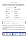
Conventions Used in this Guide
In this user guide, the following are used:
NOTE: A note draws attention to important information.
TIP: A tip provides a suggestion to make working with the application easier.
CAUTION: A caution indicates a potential hazard to equipment or data.
WARNING: A warning warns of things or actions that might cause injury, death, or
other severe consequences.
Commands are written in the fonts shown here:
^AR Merge Scene,,Op1 scene 1,1 ^B 51 ^W^C
[01] R 0004 00300 00400 00800 00600 [02] 35 [17] [03]
E X! *X1&* X2)* X2#* X2! CE}
NOTE: For commands and examples of computer or device responses mentioned
in this guide, the character “0” is used for the number zero and “O”
represents the capital letter “o.”
Computer responses and directory paths that do not have variables are written in the font
shown here:
Reply from 208.132.180.48: bytes=32 times=2ms TTL=32
C:\Program Files\Extron
Variables are written in slanted form as shown here:
ping xxx.xxx.xxx.xxx —t
SOH R Data STX Command ETB ETX
Selectable items, such as menu names, menu options, buttons, tabs, and field names are
written in the font shown here:
From the File menu, select New.
Click the OK button.
Contents
Introduction............................................. 1
HTML Control and IPL File Manager...... 28
About this Guide.............................................. 1
About the GSS 100 Graphic Still Store.............. 1
Features............................................................ 2
Configuring the Hardware.............................. 29
PC Configuration........................................ 29
Initial Startup.............................................. 29
GSS Configuration...................................... 29
Opening the Embedded Web Pages................ 32
Status Tab....................................................... 33
System Status Page..................................... 33
Configuration Tab........................................... 34
System Settings Page.................................. 34
Video Settings Page.................................... 37
Passwords Page.......................................... 38
Email Alerts Page........................................ 39
Firmware Upgrade Page.............................. 39
File Management Tab...................................... 41
File Management Page................................ 41
Control Tab..................................................... 42
Control Page............................................... 42
Images Tab..................................................... 43
Image Settings Page.................................... 43
Installing the IPL File Manager and
Uploading Images.......................................... 45
Installing the IPL File Manager..................... 45
Uploading Image Files................................. 45
Special Characters.......................................... 47
Installation............................................... 3
Mounting the GSS............................................ 3
Rear Panel Connections.................................... 3
Power Connection........................................ 4
Signal Connections....................................... 4
Remote Connections..................................... 4
Reset Button................................................. 6
Front Panel Controls and Indicators................... 7
Front Panel Operations...................................... 8
Power-on Indications..................................... 8
Selecting an Image to Display........................ 9
Muting the Video Output.............................. 9
Menu System Overview............................... 10
Front Panel Security Lockout
(Executive Mode)....................................... 16
Front Panel Absolute Reset.......................... 16
Programming Guide............................... 17
Simple Instruction Set Control......................... 18
Symbols...................................................... 18
GSS-initiated (Unsolicited) Messages........... 19
Host-to-GSS Instructions............................. 20
Error Responses.......................................... 21
Timeout...................................................... 21
Using the Command and Response
Tables........................................................ 21
Command and Response Table for
IP- and Port-specific SIS Commands........... 26
Reference Information........................... 48
Specifications.................................................. 48
Part Numbers.................................................. 51
Mounting Options...................................... 51
Cables........................................................ 51
Mounting the Unit.......................................... 52
Tabletop Placement..................................... 52
Rack Mounting........................................... 52
Furniture Mounting..................................... 53
GSS 100 Graphic Still Store • Contents
i
GSS 100 Graphic Still Store • Contents
ii
Introduction
This section introduces the Extron® GSS 100 Graphic Still Store, including:
zz
About this Guide
zz
About the GSS 100 Graphic Still Store
zz
Features
About this Guide
This manual contains installation and operating information for the Extron GSS 100 Graphic
Still Store.
NOTE: Throughout this guide, the unit is identified as either "GSS 100," the “GSS,” or
the “graphic still store.”
About the GSS 100 Graphic Still Store
The Extron GSS 100 (see figure 1) is a portable graphic still store with 16 MB of memory,
into which you can load up to 6 XGA (1024 x 768) bitmap images (BMP) or 32 or more
(depending on the compression rate) XGA JPG still images. The GSS can then output them
in an RGB video format. The GSS provides a pass-through RGB video input, in addition to
the stored images, and allows you to switch the output between the input and one of the
stored images. This allows you to display a still image of your own choosing, such as a logo,
text, or a landscape, during meeting breaks or while you load or make last minute edits to a
presentation on a laptop computer.
TCP/IP
Network
Graphics PC
-23
2
RS
V
LAN
RES
ET
H
RU
-TH
SS B
B PA
RG
V
G
H
R
B
.1A
MA
X
G
TP
UT
OU
0V
-24
100
Extron
GSS 100
R
60
50/
Hz
Graphic Still Store
Multiple Images
(for recall during
presentations)
Projector
Laptop
Figure 1. Typical GSS 100 Application
GSS 100 Graphic Still Store • Introduction
1
User-selected images, including the test patterns, can be uploaded to the GSS via its
Ethernet port using HTML pages built into the GSS. The pass-through RGB input and the
output are via female BNC connectors.
The GSS provides 16 MB of RAM for storage, providing room for up to 17 uploaded bitmap
images. The number of images that the GSS can accommodate depends on the resolution
of the images. Table 2 shows the number of BMP images that the GSS can accommodate,
based on several common resolutions.
Table 2. Approximate Image Space for BMP Files
Resolution
Size
Image space
640x480
800x600
1024x768
1280x1024 1400x1050
900 kB
1400 kB
2400 kB
4000 kB
4400 kB
17
11
6
4
3
NOTE: Because of the variable compression schemes for JPG images, there is no reliable
method to calculate the number of JPG images that the GSS can hold.
• Progressive JPG images are not supported.
• Bitmap (BMP) images must be formatted as 24-bit RGB.
The graphic still store is housed in a rack-mountable, 1U high, half rack-width metal
enclosure. The internal 100 VAC to 240 VAC, 50-60 Hz, 15-watt, power supply provides
worldwide power compatibility.
Features
zz
16 MB of internal memory storage — Sufficient for 6 XGA resolution (1024 x 768)
BMP graphics, or 32 or more JPG images at XGA resolution, depending on the
compression rate.
zz
Input pass-through mode
zz
Cut or dissolve switch effect between stored images
zz
Slide show effect automatically cycles through images.
zz
Auto-switch mode — Automatically switches to the selected stored image or a slide
show when sync is lost on the pass-through input.
zz
Rack and under-desk mountable
zz
Worldwide internal power supply
GSS 100 Graphic Still Store • Introduction
2
Installation
This section details the installation of the GSS 100, including:
zz
Mounting the GSS
zz
Rear Panel Connections
Mounting the GSS
CAUTION: Installation and service must be performed by authorized personnel only.
Detailed mounting instructions can be found in the “Reference Information“
section. The 1U high, half-rack width GSS 100 can be placed on a tabletop,
mounted on a rack shelf, or mounted under or through furniture. Use the applicable
optional hardware:
zz
RSU 129 9.5-inch deep universal rack shelf kit (part number 60-190-01)
zz
RSB 129 9.5-inch deep basic rack shelf (part number 60-604-02)
zz
MBU 125 Under-desk mount kit (part number 70-077-01)
zz
MBD 129 Through-desk mount kit (part number 70-077-02)
Rear Panel Connections
All connectors are on the rear panel (see figure 2).
2
100-240V
RGB PASS-THRU
.3A MAX
R
G
B
H/HV
V
LAN
RS-232
RESET
R
G
OUTPUT
B
H/HV
V
50/60 Hz
1
3
4
6
5
Figure 2. GSS 100 Graphic Still Store Rear Panel
GSS 100 Graphic Still Store • Installation
3
Power Connection
a AC power connector — Plug a standard IEC power cord into this connector to connect
the GSS to a 100 VAC to 240 VAC, 50 or 60 Hz power source.
Signal Connections
b RGB Pass-through connectors — Connect a high resolution or computer input (VGA,
SVGA, XGA, SXGA, or UXGA) to these female BNC connectors.
c Output connectors — Connect an RGB video display or other device to these female
BNC connectors (see figure 3 to connect the RGB video format for each configuration).
RGBHV
R
G
B
H/HV
V
G
B
H/HV
V
RGBS
R
Figure 3.
Video Output Connection Format
NOTE: The still image output format (RGBHV or RGBS) must be configured using
the front panel controls or a Simple Instruction Set (SIS™) command. The
output format applies only to the output of still images stored in the GSS;
the RGB Pass-through video is output exactly as it is input.
Remote Connections
Ethernet connection
d LAN port — Connect the GSS to a PC or to an Ethernet LAN, via this RJ-45 connector.
You can use the HTML pages embedded in the GSS to upload still images from the PC
to the GSS and to control the GSS. You can also use a PC to control the GSS with SIS
commands.
Link LED indicator — The green (link) LED indicates that the GSS 100 is
properly connected to an Ethernet LAN. This LED should light steadily.
Activity Link
LED LED
Act LED indicator — The yellow (activity) LED indicates transmission
of data packets on the RJ-45 connector. This LED should flicker as the
GSS 100 communicates.
Cabling
It is vital that your Ethernet cables be the correct cable type and that they be correctly
terminated with the proper connector pinout. Ethernet links use Category (CAT) 3, 5e, or 6,
unshielded twisted pair (UTP) or shielded twisted pair (STP) cables, terminated with RJ-45
connectors. Ethernet cables are limited to a length of 328 feet (100 m).
NOTES: • Do not use standard telephone cables. Telephone cables do not support
Ethernet or Fast Ethernet.
• Do not stretch or bend cables. Transmission errors can occur.
The cable used depends on your network speed. The GSS 100 supports both
10 Mbps (10Base-T — Ethernet) and 100 Mbps (100Base-T — Fast Ethernet), half-duplex
and full-duplex Ethernet connections.
zz
10Base-T Ethernet requires CAT 3 UTP or STP cable at minimum.
zz
100Base-T Fast Ethernet requires CAT 5e UTP or STP cable at minimum.
GSS 100 Graphic Still Store • Installation
4
RJ-45 connector wiring
The Ethernet cable can be terminated as a straight-through cable or a crossover cable and
must be properly terminated for your application (see figure 4).
zz
Crossover cable — Direct connection between the computer and the GSS 100
zz
Patch (straight) cable — Connection of the GSS 100 to an Ethernet LAN
Crossover Cable
Pins:
12345678
Pin
Insert Twisted
Pair Wires
RJ-45
Connector
End 1
Wire color
End 2
Wire color
End 1
Wire color
Pin
End 2
Wire color
1 White-green
White-orange
1 White-orange
White-orange
2 Green
Orange
2
Orange
Orange
3 White-orange
White-green
3 White-green
White-green
4 Blue
Blue
4 Blue
Blue
5 White-blue
White-blue
5 White-blue
White-blue
6 Orange
Green
6
Green
7 White-brown
White-brown
7 White-brown
White-brown
8 Brown
Brown
8 Brown
Brown
T568A
Green
T568B
A cable that is wired as T568A at one end
and T568B at the other (Tx and Rx pairs
reversed) is a "crossover" cable.
Figure 4.
Straight-through Cable
T568B
T568B
A cable that is wired the same at both ends is
called a "straight-through" cable, because
no pin/pair assignments are swapped.
RJ-45 Connector and Pinout Tables
Serial connection
e RS-232 port — Connect a computer or control system to this 9-pin D connector to
allow remote control using the SIS commands (see figure 5 and the “Programming
Guide” section).
RS-232
5
1
9
6
Figure 5.
Pin RS-232 Function
1
— Not used
2
Tx Transmit data
3
Rx Receive data
4
— Not used
5
Gnd Signal ground
6
— Not used
7
— Not used
8
— Not used
9
— Not used
RS-232 Connector Pinout
GSS 100 Graphic Still Store • Installation
5
Reset Button
f Reset button — The Reset button initiates three levels of reset to the GSS. Press and
hold the button while the GSS is running or while you power up the GSS for different
reset levels.
zz
Events (mode 3) reset — Hold the Reset button for approximately 3 seconds (the
Reset LED blinks once), then release it and push it again for a moment to toggle
events monitoring on and off.
zz
IP settings (mode 4) reset — Hold the Reset button for approximately 6 seconds
(the Reset LED blinks twice), then release it and push it again for a moment to reset
the IP functions of the GSS.
zz
Absolute (mode 5) reset — Hold the Reset button for approximately 9 seconds
(the Reset LED blinks three times), then release it and push it again for a moment to
restore the GSS to the default factory conditions.
NOTE: The absolute (mode 5) reset clears all image files, IP settings, and user
settings and resets the graphic still store to the factory default.
GSS 100 Graphic Still Store • Installation
6
Operation
This section describes the front panel operation of the GSS 100, including:
zz
Front Panel Controls and Indicators
zz
Front Panel Operations
Front Panel Controls and Indicators
Figure 6 shows the controls and indicators on the front panel of the GSS 100. See “Front
Panel Operations” for details on using these controls and indicators.
GSS 100
IMAGE
MENU
TAKE
NEXT
ADJUST/
SELECT
1
2
3
4
5
6
Figure 6. GSS 100 Front Panel
a Image button — Press this button to activate the menu on the LCD display (c) that
allows you to select between the pass-through input and one of the stored images.
b Take button — Press this button to select either the pass-through input or one of the
stored images.
c LCD display — The 8-column by 2-line LCD screen displays output and configuration
menus and status information.
d Menu button — Press the Menu button to enter and move through the main menu
system in the GSS.
e Next button — Press the Next button to step through the submenus in the GSS menu
system.
f Adjust/Select knob — Rotate the Adjust/Select knob to change settings when it is
used in conjunction with the Image and Take buttons or the Menu and Next buttons.
GSS 100 Graphic Still Store • Operation
7
Front Panel Operations
Plug in all system components and turn on the input device (such as a desktop or laptop
computers) and the output monitor. Use the LAN port to upload one or more still images to
the GSS. Select either the pass-through input or one of the stored still images to output (see
“Selecting an Image to Display”). The image should appear on the monitor connected to
the output.
Power-on Indications
Power is applied when the power cord is connected between the GSS and an AC source.
When AC power is applied, the GSS performs a self-test that shows the model name and
the firmware version in the LCD display. After approximately 15 seconds, the LCD diplays
its default cycle, alternating among four displays that show the model name, the currently
displayed image (the pass-through input or the file name of one of the previously loaded
images), the output resolution (of a stored image only; the pass-through input is output
exactly as it is input), and the IP address of the unit (see figure 7).
The current settings are saved in nonvolatile memory. When power is applied, the latest
configuration is retrieved.
NOTE: On figure 7 and all other flowcharts in this chapter, dashed lines indicate screen
changes that are the result of a timeout function.
Power
on
Default Cycle
Extron
GSS 100
Viewing
PassThru
3 sec.
Version
n.nn
3 sec.
Extron
GSS 100
3 sec.
or
3 sec.
Viewing
Image
1024 x
768 @72
3 sec.
I192.168
P255.255
3 sec.
or
RGB
PASSTHRU
Figure 7. LCD Power-on Displays and Default Display Cycle
NOTE: If the displayed file name is too large (more than eight characters, including the
file extension) for the LCD, the LCD shifts the file name:
Viewing
Largefil
Viewing
lename.jp
Viewing
ename.jpg
GSS 100 Graphic Still Store • Operation
8
Selecting an Image to Display
NOTES: • The only valid file formats for uploaded image files are BMP and JPG.
• Valid file names are up to 240 alphanumeric characters with no spaces.
• Progressive JPG images are not supported.
• Bitmap (BMP) images must be formatted as 24-bit RGB.
• 1080i and 1080p files need to be mastered at a resolution of
1440 x 1080 instead of the expected 1920 x 1080.
Select an image to display as follows:
1. Press and release the Image button (see figure 8).
Step 1
Step 2
Step 3
IMAGE
TAKE
ADJUST/
SELECT
Select
PassThru
or
Loading
Image
Default
Cycle
Select
Filename
Figure 8.
Selecting an image
2. Rotate the Adjust/Select knob to select either PassThru or one of the previously loaded
images by file name.
3. Press and release the Take button. The LCD shows Loading Image and then returns to
the default display cycle once the image is loaded.
Muting the Video Output
To toggle the video output mute on and off, press and hold the Take button for
approximately 3 seconds (see figure 9). When the video output is muted (video is not
output), an asterisk (*) appears and blinks in the LCD default display cycle, in either the
output resolution display or the RGB pass-through display. When the video output is
unmuted (video is output), the asterisk is not present.
Muting the
Output
TAKE
3
Sec.
Unmuting the
Output
TAKE
Release the
button.
Press and
hold.
3
Sec.
Press and
hold.
*1024 x
768 @72
Default
Cycle
Release the
button.
Asterisk (*)
blinks to indicate
the output is muted.
* RGB
PASSTHRU
1024 x
768 @72
Default
Cycle
Asterisk (*)
goes out to indicate
the output is unmuted.
RGB
PASSTHRU
Figure 9. Muting and Unmuting the Output
GSS 100 Graphic Still Store • Operation
9
Menu System Overview
Figure 10 shows a flowchart of the main menus in the menu system.
Power
on
Extron
GSS 100
3 sec.
Version
n.nn
3 sec.
Menu
10 sec.
10 sec.
Menu
Switch
Effect
Output
Config
10 sec.
Menu
Slide
Show
Default
Cycle
Menu
10 sec.
Advanced
Menu
Menu
10 sec.
Menu
Next
Exit
Menu
Figure 10.Menu System Flowchart
Menu button — Press the Menu button to activate the menu system and to scroll through
the five main menus.
Next button — Press the Next button to move between the submenus of a selected main
menu, to activate one for viewing or configuration, and to save a selection.
Adjust/Select knob — When in a submenu, rotate the Adjust/Select knob to scroll through
the submenu options and select a setting. See the flowcharts in this section and specific
subsections for explanations of knob adjustments.
NOTES: • To return to the default cycle, let the GSS remain idle for 30 seconds until
the selected screen times out, or press the Menu button until the Exit Menu
appears, then press the Next button.
• From any menu or submenu, after 30 seconds of inactivity, the GSS saves all
adjustment settings and times out to the default LCD display cycle.
• The GSS saves settings to its non-volatile memory every 3 minutes. Ensure
that you wait at least 3 minutes after making any changes or those changes
may be lost.
Switch Effect menu
Figure 11 is a flowchart that shows an overview of the Switch Effect menu and the available
settings.
Power
on
Default
Cycle
Menu
10
sec.
10
sec.
10
sec.
10
sec.
10
sec.
Menu
Switch
Effect
Next
Menu
Effect
Cut
10 sec.
Next
Menu
10 sec.
Duration Next
0.0 Secs
Menu
Output
Config
Menu
Output transition
• Cut • Dissolve
Dissolve duration
0.0 to 5.0 seconds in
0.1 second increments.
Slide
Show
Menu
Advanced
Menu
Menu
Exit
Menu
Figure 11.Switch Effect Menu Flowchart
GSS 100 Graphic Still Store • Operation
10
Effect submenu
Rotate the Adjust/Select knob while in the Effect submenu to cut (immediate switch) and
dissolve (the image dissolves from old to new). Cut is the default selection.
Duration submenu
Rotate the Adjust/Select knob while in the Duration submenu to select the duration for the
dissolve effect (if it is selected), between 0.0 and 5.0 seconds in 0.1 second increments. The
default duration is 1.0 seconds.
Output Configuration menu
Figure 12 is a flowchart that shows an overview of the Output Configuration menu and the
available settings.
Power
on
Default
Cycle
Menu
10 sec.
Next
1024 x
768 @60
Menu
10
sec.
10
sec.
10
sec.
10
sec.
10
sec.
Menu
Menu
10 sec.
Next
Sync
RGBHV
Switch
Effect
Menu
Output
Config
Next
Resolution
See the table
on page 12.
Output sync format
• RGBHV • RGBS
Menu
Slide
Show
Menu
Menu
10 sec.
H Pol V
Neg Neg
Menu
10 sec.
RGB Dly Next
0.0 Sec
Advanced
Menu
Menu
Exit
Menu
Sync polarity
• H-/V- • H+/V• H-/V+ • H+/V+
Cut duration
0.0 to 5.0 seconds in
0.1 second increments.
Figure 12.Output Configuration Submenu
NOTE: The Output Configuration menu settings apply only to the output of still images
stored in the GSS; the RGB Pass-through video is output exactly as it is input.
GSS 100 Graphic Still Store • Operation
11
Resolution submenu
Rotate the Adjust/Select knob while in the Resolution submenu to select the resolution of
the stored image output. 1024 x 768 at 60 Hz is the default resolution.
NOTE: To view an uncropped full screen image at 1080p or 1080i, the image resolution
must be 1440 x 1080.
Resolution
50
Hz
60
Hz
72
Hz
96
Hz
100
Hz
120
Hz
640 x 480
•
•
•
•
•
•
800 x 600
•
•
•
•
•
•
852 x 480
•
•
•
•
•
1024 x 768
•
•
•
•
1024 x 852
•
•
•
•
1024 x 1024
•
•
•
1280 x 768
•
•
1280 x 800
•
•
1280 x 1024
•
•
1360 x 765
•
•
1365 x 768
•
•
1366 x 768
•
•
1365 x 1024
•
•
1400 x 1050
•
•
1440 x 900
•
•
480p
•
•
576p
•
•
720p
•
•
1080i
•
•
1080p
•
•
Sync format submenu
Rotate the Adjust/Select knob while in the Sync format submenu to select the sync format
for the still image output. RGBHV is the default selection.
Sync polarity submenu
Rotate the Adjust/Select knob while in the Sync polarity submenu to select the sync polarity
(positive and negative) for the still image output. Horizontal and vertical negative sync are
the default selection.
RGB Delay submenu
The GSS can briefly blank the RGB (video) output while it switches between the stored
image and the pass-through image. This allows the change in display to appear without a
glitch. RGB delay is also known as Triple-Action Switching or video mute switching.
Rotate the Adjust/Select knob while in the RGB Delay submenu to set the delay between
0 and 5 seconds, in 0.1-second increments. No delay (0.0 seconds) is the default setting.
GSS 100 Graphic Still Store • Operation
12
Slide Show menu
Figure 13 is a flowchart that shows an overview of the Slide Show menu and the available
settings.
Power
on
Default
Cycle
Menu
10
sec.
10
sec.
10
sec.
10
sec.
10
sec.
Menu
Switch
Effect
Menu
Output
Config
Menu
Slide
Show
Next
Menu
10 sec.
Duration Next
030 Secs
Menu
10 sec.
PassThru Next
Disabled
Menu
Advanced
Menu
Menu
Duration
0 to 300 seconds in
1 second increments
Pass-Thru Input
• Disabled
• Enabled
Exit
Menu
Figure 13.Slide Show Submenu Flowchart
Duration submenu
Rotate the Adjust/Select knob while in the Duration submenu to set the duration of each
displayed image in the slide show between 0 and 300 seconds, in 1-second increments. The
default duration is 30 seconds.
NOTE: The actual time that an image is displayed may vary, based on the decoding time
of the next image in the slide show.
Pass-Thru submenu
Rotate the Adjust/Select knob while in the Pass-Thru submenu to enable or disable the
inclusion of the pass-through input as part of the slide show. The pass-through input is
disabled from being part of the slide show by default.
GSS 100 Graphic Still Store • Operation
13
Advanced menu
Figure 14 is a flowchart that shows an overview of the Advanced menu and the available
settings.
Menu
10 sec.
Auto Sw Next
Off
Default
Cycle
Power
on
Menu
10
sec.
10
sec.
10
sec.
10
sec.
10
sec.
Menu
Menu
Name
GSS-100-
3 sec.
{scroll}
Name
nn-nn-nn
10 sec.
Next
Name (Display Only)
(Changeable under RS-232/Ethernet control;
scrolls to the left if greater than 8 characters.)
Auto Switch
• Off
• Off/show
• On/still • On/show
Switch
Effect
Menu
Output
Config
Menu
nn:nn:nn
nn:nn:nn
Menu
Slide
Show
MAC Address
(Display Only)
Menu
Advanced
Menu
Next
Next
Menu
Int Temp
113F 45C
Next
Temperature
(Display Only)
Menu
Exit
Menu
Baud Rate
• 2400
• 19200
• 4800
• 38400
• 9600
• 115200
Menu
RS-232
9600
TAKE
Next
Press Take to
enable changing
the value.
Rotate Adjust/
Select to change
the value.
Menu
I192.168
P254.254
TAKE
Next
Press Take to enable
changing the value
and select an octet.
Rotate Adjust/Select
to change the value in
the selected (blinking)
octet.
Figure 14.Advanced Submenu Flowchart
Auto Switch (and slide show) submenu
The GSS can be set to an auto-switch mode that monitors the sync signal on the RGB passthrough input and automatically switches to the last-displayed stored image or slide show
for output when sync is lost. This submenu also allows you to turn the auto-switching and
slide show on and off.
Rotate the Adjust/Select mode while in the Auto-Switch submenu to select:
zz
Off (auto-switch mode off and slide show off) — Deactivates the automatic sync
detection and the slide show.
zz
Off/show (auto-switch off and slide show on) — Leaves the automatic sync
detection off and manually initiates the slide show. If the pass-through input was being
displayed when this selection is made, the GSS displays the first image alphabetically by
file name.
zz
On/still (auto-switch on and slide show off) — Activates the automatic sync
detection and auto-switches to the still image. If sync is lost, the GSS switches to the last
displayed image that was output and outputs that image until sync is restored or you
select another image to display.
zz
On/show (auto-Switch on and slide show on) — Activates the automatic sync
detection and auto-switches to the slide show. If sync is lost, the GSS switches to the
last-displayed image and begins to cycle through the available images.
The default setting is Off.
GSS 100 Graphic Still Store • Operation
14
Name display
The read-only Name display shows either the factory default name or a customized name
that can be assigned under RS-232 or Ethernet control. If the name is greater than eight
characters, the display shows the first eight characters of the assigned name and then scrolls
the name to the left to display the remaining characters of the name.
The factory default name is the product name (GSS-100-) plus the last three pairs of
the MAC address (see the “Programming Guide“ and “HTML Control and IPL File
Manager“ sections to assign a name).
MAC Address display
The read-only MAC Address display shows the hardcoded, factory assigned hardware
address.
Internal Temperature display
The read-only Internal Temperature display shows the Fahrenheit and Celsius measurements
for the GSS temperature.
CAUTION: Temperatures above 150 degrees Fahrenheit (65 degrees Celsius) are
potentially damaging to the GSS.
Baud Rate submenu
The Baud Rate menu is read-only without further action. The menu shows the selected baud
rate for the RS-232 port of the GSS. The default setting is 9600.
To change the baud rate, press and release the Take button. The baud rate display starts
blinking, and can be adjusted by rotating the Adjust/Select knob.
NOTE: The baud rate is also selectable using SIS commands (see the “Programming
Guide“ section).
IP address submenu
The read-only IP address menu is read-only without further action. The menu shows the IP
address of the GSS. The factory default IP address is 192.168.254.254.
To change the IP address, one octet at a time, press and release the Take button. The first
(most-significant) octet starts blinking, and can be adjusted by rotating the Adjust/Select
knob. Repeatedly press and release the Take button to cycle through the four IP address
octets, enabling them for editing, one at a time.
NOTE: The IP address is also selectable using SIS commands or the HTML pages (see
the “Programming Guide“ and “HTML Control and IPL File Manager“
sections).
Exit menu
Press and release the Next button while in the Exit menu to return the LCD to the default
display cycle.
GSS 100 Graphic Still Store • Operation
15
Front Panel Security Lockout (Executive Mode)
The front panel security lockout (lock mode 1) limits the operation of the GSS from the
front panel. When the GSS is locked, the front panel Menu and Next buttons are disabled,
although the Image and Take buttons are still functional. If you push the Menu or Next
button when the GSS is locked, the LCD shows X Mode Enabled for approximately
5 seconds and then returns to the default display cycle.
To toggle the lock on and off (lock mode 0), press and hold the Image button and the Next
button for approximately 2 seconds.
NOTE: Lock mode 2, available using SIS commands only, completely locks the front
panel, including the Image and Take buttons. Lock mode 2 can also be disabled
using SIS commands only (see the “Programming Guide“ section).
Front Panel Absolute Reset
The GSS 100 can be reset from the front panel, resetting the unit to its factory default
conditions and deleting all uploaded images. Reset the GSS by pressing and holding the
Menu and Next buttons while applying power to the unit (see figure 15).
Press and hold the Menu and Next
buttons while you apply power to the GSS.
MENU
NEXT
Continue to hold the
Menu and Next buttons
until the LCD displays
the Reset message.
Power
Reset to
Factory
Release the Menu
and Next buttons.
Figure 15.System Reset
NOTE: The front panel absolute reset can be used to recover a GSS that has been
inadvertently loaded with image files in incompatible formats.
GSS 100 Graphic Still Store • Operation
16
Programming
Guide
This section describes Simple Instruction Set operation of the GSS 100.
The rear panel RS-232 connector (see figure 16) can be connected to the serial port of a
host device, such as a computer or control system. Communications with the GSS are via the
Extron Simple Instruction Set (SIS).
RS-232
5
1
9
6
Pin RS-232 Function
1
— Not used
2
Tx Transmit data
3
Rx Receive data
4
— Not used
5
Gnd Signal ground
6
— Not used
7
— Not used
8
— Not used
9
— Not used
Figure 16.Remote Connector Pinout
The baud rate for the rear panel RS-232 port can be set to a variety of different rates. The
default protocol for the port is as follows:
zz
9600 baud
�
no parity
zz
8-bit, 1 stop bit
�
no flow control
GSS 100 Graphic Still Store • Programming Guide
17
Simple Instruction Set Control
Symbols
Symbols (values), defined starting below, are used throughout the discussions of the
GSS-initiated messages that begin below and the command and response table that
begins on page 22. The symbols represent variables in the GSS-initiated messages and the
command and response table fields.
]
}
= CR/LF (carriage return and line feed) (hex 0D 0A)
= Carriage return (no line feed, hex 0D)
|
= Pipe (can be used interchangeably with the } character)
•
= Space character
E = Escape key (hex 1B)
W = Can be used interchangeably with the E character
X!
= Image file name
X@
=Status:
On / off
Busy
Cut / dissolve
Pass-through
Image name with file extension (*.bmp or *.jpg)
(Up to 240 alphanumeric characters with no spaces)
0 = off
0 = free
0 = cut
0 = pass-thu
1 = on
1 = busy
1 = dissolve
1 = no pass-thru
X#
= Time
00 – 50 (0.0 to 5.0 seconds) for RGB delay and dissolve duration
000 – 300 seconds for slide show interval
X$
= Auto-switch / slide show
0 = off
1 = off / show
X%
= Resolution
0 = 640 x 480
1 = 600 x 600
2 = 852 x 480
3 = 1024 x 768
4= 1024 x 852
5 = 1024 x 1024
6 = 1280 x 768
7 = 1280 x 1024
8 = 1360 x 765
9 = 1365 x 768
X^
= Refresh rate
0 = 50 Hz
1 = 60 Hz
2 = 72 Hz
3 = 96 Hz
4 = 100 Hz
5 = 120 Hz
X&
X*
= Sync format
0 = RGBHV
1 = RGBS
= Sync polarity
0 = H– / V–
1 = H– / V+
2 = H+ / V–
3 = H+ / V+
0 = unlock
1 = partial lock
2 = complete lock
1 = User 2 = NVRAM
X( = Front panel Lock mode
X1) = Event number
X1! = Event buffer
X1@ = Even buffer offset
X1# = Event data size
2 = on / still
3 = on / show
10 = 1366 x 768
11 = 1365 x 1024
12 = 1400 x 1050
13 = 480p
14 = 576p
15 = 720p
16 = 1080i
17 = 1080p
18 = 1280 x 800
19 = 1440 x 900
00 through 99
0 = Receive
00 through maximum buffer size
b = bit
B = byte
S = short (16 bits)
L = long (32 bits)
NOTE:The X1# parameter is case sensitive.
X1$ = ASCII digits representing the numeric value of the data element read from the event buffer (leading zeroes are suppressed)
X1% = Event status fields
Event type
Event state
Event paused
Error status
RcvBuff_startptr
RcvBuff_endptr
UsrBuff_Startptr
UsBuff_endptr
GSS 100 Graphic Still Store • Programming Guide
18
X1^ = Event data to write
X1& = Number of bytes to read
X1* = Pass-through sync status
0 = No sync detected
1 = V sync detected
X1( = Bytes of memory used
X2) = Firmware version
2 = H sync detected
3 = HV (composite) sync detected
nnnnnnn (bytes)
n.nn
GSS-initiated (Unsolicited) Messages
When a local event, such as an equipment power-up, occurs, the GSS responds by sending
a message to the host. The GSS-initiated messages are listed in the following pages. The
messages are underlined.
The GSS does not expect a response from the host, but the host program may request a new
status.
Power-up
(c) Copyright 2010, Extron Electronics, GSS 100, Vx.xx]
The GSS 100 issues the Copyright message (above) when it first powers on. Vx.xx is the
firmware version number.
Image selection
Take]
Bsy1]
Bsy0]
The GSS issues the above sequence of commands when a front panel image selection
operation or a slide show image change occurs.
zz
The Take message indicates the change of output image.
zz
The Bsy1 message indicates to the connected control device that the GSS is busy
processing the cut or dissolve transition and is unable to respond to input commands.
zz
The Bsy0 message indicates that the GSS is no longer busy and can respond to input
commands.
Switch effect
EffX#]
The GSS 100 initiates the Eff message when a front panel change in the image switch
effect takes place.
DurX#]
The GSS 100 initiates the Dur message when a front panel change in the dissolve duration
takes place.
GSS 100 Graphic Still Store • Programming Guide
19
Output configuration
NOTE: The output configuration settings apply only to the the output of still images
stored in the GSS; the RGB pass-through video is output exactly as it is input.
RteX%*X^]
The GSS 100 initiates the Rte message when a front panel change in the output resolution
takes place.
SynX&]
The GSS 100 initiates the Syn message when a front panel change in the output sync format
takes place.
PolX*]
The GSS 100 initiates the Pol message when a front panel change in the output sync
polarity takes place.
DlyX#]
The GSS 100 initiates the Dly message when a front panel change in the RGB delay interval
takes place.
Auto-switch and slide show control
PasX@]
The GSS 100 initiates the Pas message when a front panel change in the pass-through
configuration takes place.
AutX$]
The GSS 100 initiates the Aut message when a front panel change in the auto-switch and
slide show on and off status takes place.
SliX#]
The GSS 100 initiates the Sli message when a front panel change in the slide display
duration takes place.
Front panel locks
ExeX@]
The GSS 100 initiates the Exe message when a front panel change in the front panel lock on
or off status takes place.
Host-to-GSS Instructions
SIS commands consist of one or more characters per field. No special characters are required
to begin or end a command character sequence. When a command is valid, the unit
executes the command and sends a response to the host device. All responses from the unit
to the host end with a carriage return and a line feed (CR/LF = ]), which signals the end of
the response character string. A string is one or more characters.
GSS 100 Graphic Still Store • Programming Guide
20
Error Responses
When the GSS 100 receives a valid SIS command, it executes the command and sends a
response to the host device. If the unit is unable to execute the command because the
command is invalid or it contains invalid parameters, the unit returns an error response to
the host. The error response codes are:
E10 — Invalid command
E13 — Invalid value (out of range)
E14 — Illegal command for this configuration
E17 — Timeout (caused only by direct write of global presets)
E22 — Busy
E24 — Privilege violation (Ethernet, Extron software only)
E25 — Device not present
E26 — Maximum number of connections exceeded
E27 — Invalid event number
E28 — Bad filename or file not found
Timeout
Pauses of 10 seconds or longer between command ascii characters result in a timeout. The
command operation is aborted with no other indication.
Using the Command and Response Tables
The command and response table begins on the next page. Either uppercase or lowercase
letters are acceptable in the command field except where indicated for the audio level (gain
and attenuation) commands. Symbols are used throughout the table to represent variables in
the command/response fields. Command and response examples are shown throughout the
table. The ASCII to Hex conversion table below is for use with the command and response
table.
Space
ASCII to Hex Conversion Table
•
GSS 100 Graphic Still Store • Programming Guide
21
Command and Response Table for SIS Commands
Command
ASCII Command
Response
(Host to Unit)
(Unit to Host)
EX!RF}
Cim•X!]
Additional description
Image recall
Recall an image to buffer
Select image X! to display.
NOTE: It takes several seconds between the issuance of the recall command (EX!RF}) and the receipt of the Cim response.
ERF}
X!]
The buffer is loaded with image X!.
%
Tke]
Swap the displayed and buffered images using the
selected effect (cut or dissolve).
9*0#
9*1#
9#
10*X##
10#
Eff0]
Eff1]
Set the effect for switching images to cut (immediate).
Set the effect for switching images to dissolve.
X@]
DurX#]
X#]
Set the duration of the dissolve effect to X#.
The dissolve duration is X#.
Display pass-through
Display last image
1!
0!
Chn1]
Chn0]
Display the pass-through input.
Display the previously selected stored image.
View pass-through status
!
X@]
Pass-through mode is X@.
Set slide show interval
2*X##
SliX#]
Set the display time for each image to X# seconds.
Read slide show interval
2#
X#]
The display time for each image is X# seconds.
Pas1]
Pas0]
Include the pass-through input in the slide show.
Do not include the pass-through input in the slide show.
Show the status of the pass-through.
Show the image that is
currently displayed
Take
Switch effect
Set the effect to cut
Set the effect to dissolve
Read the effect
Set the dissolve duration
Read the dissolve duration
Source selection
Slide show interval
Pass-through configuration
Enable pass-through
Disable pass-through
Read the pass-through status
1*1#
1*0#
1#
X@]
Auto-switch and slide show mode
Set auto-switch and slide
show mode
4*X$#
AutX$]
Show auto-switch and slide
show mode
4#
X$]
NOTE:
X! = Image file name
X@ = Cut / dissolve status:
Pass-through status:
X# = Time (duration)
X$ = Auto-switch / slide show
Set auto-switch and slide show mode. X$ definitions:
0 = Off — Auto-switch on loss of pass-through sync
and slide show are disabled.
1 = Off/show — Auto-switch on loss of pass-through
is disabled. Slide show is running.
2 = On/still — On loss of sync on the pass-through
input, auto-switch to display the lastdisplayed image until pass-through
sync is restored.
3 = On/show — On loss of sync on the pass-through
input, auto-switch to run the slide
show until sync on the pass-through
input is restored.
Image name with file extension (*.bmp or *.jpg)
0 = cut
1 = dissolve
0 = pass-thu
1 = no pass-thru
00 – 50 (0.0 to 5.0 seconds) for dissolve duration
000 – 300 seconds for slide show interval
0 = off
2 = on / still
1 = off / show
3 = on / show
GSS 100 Graphic Still Store • Programming Guide
22
Command/Response Table for SIS Commands (continued)
Command
ASCII Command
Response
(Host to Unit)
(Unit to Host)
X%*X^=
RteX%*X^]
Additional description
Output rate
Set the output rate
Set the output resolution for the stored image to X%
at X^ Hz.
NOTE: The output rate (=) command affects the display of the stored images only; pass-through sources are output exactly as they are
input.
Example:
Read output rate
3*1=
Rte3•1]
=
X%*X^]
Set the output resolution for the stored image to
1024 x 768 at 60 Hz.
The output resolution of the stored image is X% at X^ Hz.
6*X&#
SynX&]
Set the output sync format of the stored image to X&.
Output sync
Set the output sync format
NOTE: The output sync format (6#) command affects the display of the stored images only; pass-through sources are output exactly as
they are input.
Example:
View output sync format
Set the output sync polarity
6*0#
Syn0]
6#
X&]
PolX*]
7*X*#
Set the output sync format for the stored image to
RGBHV.
The output sync format for the stored image is X&.
Set the output sync polarity of the stored image to X*.
NOTE: The output sync polarity (7#) command affects the display of the stored images only; pass-through sources are output exactly as
they are input.
Example:
View the output sync
polarity
7*0#
Pol0]
7#
X*]
Set the output sync polarity for the stored image to
H– and V–.
The output sync polarity for the stored image is X*.
RGB delay (for pass-through)
Set RGB delay
8*X##
DlyX#]
Read RGB delay
8#
X#]
1B
0B
B
Vmt1]
Vmt0]
Set the RGB delay value (video mute) before displaying
the RGB pass-through input to X#.
Video mute
Mute video
Unmute video
Show video mute status
Mute the output video (black screen)
Unmute the output video (output video)
X@]
Front panel lock (Executive mode)
Partially lock front panel
1X
Exe1]
Completely lock front panel
Unlock front panel
Show front panel lock status
2X
0X
X
Exe2]
Exe0]
NOTE:
Partially lock the front panel. Only the Image and Take
buttons function.
Lock all front panel functions.
Unlock the front panel.
X(]
X@ = On / off status
X# = Time (duration)
X% = Resolution
0 = off
1 = on
00 – 50 (0.0 to 5.0 seconds) for RGB delay duration
0 = 640 x 480
1 = 600 x 600
2 = 852 x 480
3 = 1024 x 768
4= 1024 x 852
5 = 1024 x 1024
6 = 1280 x 768
7 = 1280 x 1024
8 = 1360 x 765
9 = 1365 x 768
10 = 1366 x 768
11 = 1365 x 1024
12 = 1400 x 1050
13 = 480p
14 = 576p
X^ = Refresh rate
0 = 50 Hz
1 = 60 Hz
0 = RGBHV
2 = 72 Hz
3 = 96 Hz
1 = RGBS
4 = 100 Hz
5 = 120 Hz
0 = H– / V–
0 = unlock
1 = H– / V+
1 = partial lock
2 = H+ / V–
2 = complete lock
X& = Sync format
X* = Sync polarity
X( = Front panel lock modes
15 = 720p
16 = 1080i
17 = 1080p
18 = 1280 x 800
19 = 1440 x 900
3 = H+ / V+
GSS 100 Graphic Still Store • Programming Guide
23
Command/Response Table for SIS Commands (continued)
Command
ASCII Command
Response
(Host to Unit)
(Unit to Host)
Read event buffer memory
EX1),X1!,X1@,X1#E}
X1$]
Read event status
EX1)E}
X1%]
Write event to memory
buffer
EX1),X1!,X1@,X1^,X1#E}
Read string from event
buffer memory
EX1),X1!,X1@,X1&FE}
Write string to event buffer
memory
EX1^,X1),X1!,X1@FE}
Start events
Stop events
Show # of running events
E1AE}
E0AE}
EAE}
Additional description
Event (script) control
EwrX1),X1^]
<string>]
EwrX1),X1^]
Ego]
Est]
Enmnn]
Read the contents of a specific section of a memory
buffer for event number X1).
Show the status of event X1). The following X1%
information fields are displayed: event_type, event_
state, event_paused, error_status, RcvBuff_startptr,
cvBuff_endptr, UsrBuff_startptr, and UsrBuff_endpt.
Write event X1) to buffer X1!, offset by X1@. Include
data X1^, size X1#.
Read string from event X1), buffer X1!, offset by X1@,
X1& bytes.
Write data string X1^ from event X1), buffer X1!,
offset by X1@.
Initiate all programmed events.
Stop all programmed events.
nn is the number of events running.
View, information, part number, and firmware requests
Information request
Example:
I
I
Request user memory usage
Example:
4I
4I
Request for part number
Query firmware version
N
Q
ChnX@•VmtX@•ExeX(•TypX1*]
Chn0•Vmt0•Exe1•Typ0]
Pass-through input is not displayed, video output is not
muted, panel is partially locked, no sync signal is
detected on the pass-through input.
X1)•Bytes•Used•out•of•17344•KBytes]
1149184•Bytes•Used•out•of•17344•KBytes]
This device has approximately 5850 kBytes of user
memory available (17344 kBytes – 11491 kBytes) for
additional stored images and HTML pages.
Display the GSS 100 part number.
60-684-01]
X1!]
Firmware version x.xx.
Erase all files
Master reset
EZfff}
EZxxx}
Zpf]
Zpx]
Absolute reset
EZqqq}
Zpq]
Absolute reset, retaining IP
EZY}
Zpy]
Resets
NOTE:
Erase user-supplied files. Does not reset IP settings.
Resets all user settings to their default values. Does
not reset IP settings or delete loaded image files.
Resets all device settings to their factory defaults. Erases
all loaded files. The firmware version remains unchanged.
Similar to absolute reset (EZqqq}), except that
IP settings (IP address, subnet mask, gateway
address, unit name, DHCP setting, and port mapping
[Telnet/web/Direct Access] are excluded). Preserves
communications with the device and is recommended
after a firmware update.
X@ = On or off status:
0 = off
1 = on
Pass-through status:
0 = pass-thu
1 = no pass-thru
X( = Front panel lock modes
0 = unlock
1 = partial lock
2 = complete lock
X1* = Pass-through sync status
0 = No sync detected
2 = H sync detected
1 = V sync detected
3 = HV (composite) sync detected
X1( = Bytes of memory used
nnnnnnn (bytes)
X2) = Firmware version
n.nn
X1) = Event number
00 through 99
X1! = Event buffer
0 = Receive
1 = User
2 = NVRAM
X1@ = Even buffer offset
00 through maximum buffer size
X1# = Event data size (case sensitive)
b = bit
S = short (16 bits) B = byte
L = long (32 bits)
X1^ = Event data to write
X1& = Number of bytes to read
X1% = Event status fields
See the complete list in the EX1)E} command, above
X1$ = ASCII digits representing the numeric value of the data element read from the event buffer
GSS 100 Graphic Still Store • Programming Guide
24
Command/Response Table for SIS Commands (continued)
Command
ASCII Command
Response
(Host to Unit)
(Unit to Host)
Additional description
File management
NOTE: A directory name is an alphanumeric text string that can also include the minus (-), plus (+), and colon (:) signs. Blank and space
characters are not permitted. The first character must be a letter. The directory name is not case-sensitive.
Change or create directory
Epath/directory/CJ}
Go to root directory
Go up one directory
Show current directory
E/CJ}
E..CJ}
ECJ}
Dir•path/directory/]
Dir•/]
Dir•path/directory/]
path/directory/]
NOTE: The response to the View File Directory command differs, depending on whether the command is sent via an RS-232, RS-422, or
Telnet connection or sent via a web browser connection.
View file directory
RS232/RS422 port and
Telnet
View file directory
web browser
EDF}
EDF}
<filename1>,<date/time>,<length>]
<filename2>,<date/time>,<length>]
<filename3>,<date/time>,<length>]
•
•
•
•
•
•
•
•
<filenamen>,<date/time>,<length>]
<number of Bytes>•Left]]
List user-supplied files.
Var file = new array ();
File [1] = ‘<filename1>,<date1>,<filesize1>‘;
File [2] = ‘<filename2>,<date2>,<filesize2>‘;
File [3] = ‘<filename3>,<date3>,<filesize3>‘;
E<filename>EF}
filename<n>File [<n>] = ‘<filenamen>,<daten>,<filesizen>‘;
File [<n+1>] = <number of Bytes>•Left
List user-supplied files.
{same response as above} X/ is the the first character of the file extension.
{same response as above} X/X/ is the first character of the filename and the first
character of the extension.
{same response as above} X/ is the the first character of the file extension.
{same response as above} X/X/ is the first character of the filename and the first
character of the extension.
Del<filename>]
E/EF}
Ddl]
E//EF}
Ddl]
List specific files from the
current directory
EX/DF}
EX/X/DF}
List specific files from
the current directory and
subdirectories
Erase user-supplied web
pages and files
Erase current directory and
its files
Erase current directory and
subdirectories
EX/LF}
EX/X/LF}
GSS 100 Graphic Still Store • Programming Guide
25
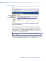
Command and Response Table for IP- and Port-specific SIS Commands
Symbol definitions
X4) = Device name
(Up to 240 alphanumeric characters)
NOTE: The following characters are invalid or not recommended in the name: {space} + ~ , @ = ` [ ] { } < > ‘ “ ” ; : | \ and ?.
X4! = Default name
X4@ = Time and date (for set)
X4# = Time and date (for read)
X4$ = GMT offset
X4% = Daylight Saving Time
X4^ = IP address
X4& = Hardware (MAC) address
X4* = Number of open connections
X4( = Password
GSS-100- + last 3 pairs of MAC address
In the format: MM/DD/YY•HH:MM:SS where:
MM = month: 01 (Jan) through 12 (Dec)
DD = day: 01 through 31
YY = year: (20)00 through (20)99
HH = hour: 00 through 23
MM = minutes: 00 through 59
SS = seconds: 00 through 59
In the format: Day,•DD•Mmm•YYYY•HH:MM:SS where:
Day = weekday: Mon through Sun
DD = date: 01 through 31
Mmm = month: Jan through Dec
YYYY = year: 2000 through 2099
HH = hour: 00 through 24
MM = minutes: 00 through 59
SS = seconds: 00 through 59
–12.0 through +14.0. Hours and minutes removed from GMT
0 = Daylight Saving Time off/ignore
1 = Daylight Saving Time on (North America)
2 = Daylight Saving Time on (Europe)
3 = Daylight Saving Time on (Brazil)
nnn.nnn.nnn.nnn
nn-nn-nn-nn-nn-nn
0 – 255
12 alphanumeric characters
NOTE: The following characters are invalid or not recommended in passwords: {space} + ~ , @ = ` [ ] { } < > ‘ “ ” ; : | \ and ?.
X5) = DHCP
X5! = Port number
X5@ = Baud rate
X5#=Parity
0 =off, 1 = on
00 – 99 (00 = all ports)
2400, 3600, 4800, 7200, 9600, 14400, 19200, 28800, 38400, 57600, 115200
odd, even, none, mark, space
NOTE: For the X5# parameter, use the first character only. The parameter is case insensitive.
X5$ = Data bits
X5% = Stop bits
X5^ = Port timeout
X5& = Verbose mode
7 or 8 (8 = default)
1 or 2 (1 = default)
The number of seconds (in 10-second steps) before timeout on the IP connections:
minimum = 1 (10 seconds), maximum = 6500 (65,000 seconds or just over 18 hours),
default = 30 (300 seconds or 5 minutes). If no data is received during the timeout period, the Ethernet
connection is closed. Applicable to Ethernet connection only; when connected via the RS-232 port, only
the global timeout commands apply.
0 = clear or none (default for Telnet connection)
1 = verbose mode (default for RS-232 or RS-422 connection)
2 = tagged responses for queries
3 = verbose mode and tagged for queries
NOTE: If tagged responses is enabled, all read commands return the constant string and the value as the set command does
(for example, the read matrix name command ECN} returns Ipn•X4)]).
GSS 100 Graphic Still Store • Programming Guide
26
Command and Response Table for IP-Specific SIS Commands
Command
ASCII Command
Response
(host to unit)
(unit to host)
Additional description
Set device name
Read device name
Reset device name to factory
default
Set time and date
Read time and date
Set GMT offset
EX4)CN}
ECN}
E•CN}
Ipn•X4)]
X4)]
Ipn•X4!]
EX4@CT}
ECT}
EX4$CZ}
IptX4@]
X4#]
IpzX4$]
Example:
Set Daylight Saving Time
Read Daylight Saving Time
E8.0CZ}
EX4%CX}
ECX}
EX4^CI}
ECI}
ECH}
ECC}
EX4^CS}
ECS}
EX4^CG}
ECG}
EX4(CA}
ECA}
E•CA}
X4%]
X4%]
IpiX4^]
X4^]
X4&]
X4*]
IpsX4^]
X4^]
IpgX4^]
X4^]
Ipa•X4(]
X4(]
Ipa•]
EX4(CU}
ECU}
E•CU}
EX5)DH}
EDH}
EX5!*X5@,X5#,X5$,X5%CP}
E01*9600,N,8,1CP}
Ipu•X4(]
X4(]
Ipu•]
X5): 0 = off, 1 = on
IdhX5)]
X5)]
CpnX5!•CcpX5@,X5#,X5$,X5%]
Cpn01•Ccp9600,N,8,1] Set the the RS-232 port to 9600
IP and port setup commands
Set IP address
Read IP address
Read hardware address
Read # of open connections
Set subnet mask
Read subnet mask
Set gateway IP address
Read gateway IP address
Set administrator password
Read administrator password
Reset (clear) administrator
password
Set user password
Read user password
Reset (clear) user password
Set DHCP on or off
Read DHCP on/off status
Set serial port parameters
Example:
“GSS-100” plus the last three pairs
of the MAC address.
In the command, the divider
between hours and minutes can be
either a colon (:) or a period. In the
response, the divider is a colon.
Ipz+08:00]
baud, no parity, 8 data bits, and 1
stop bit.
Read serial port parameters
Configure current port timeout
View current port timeout
Set global IP timeout
View global IP timeout
Set verbose mode
Read verbose mode
E01CP}
E0*X5^TC}
E0TC}
E1*X5^TC}
E1TC}
EX5&CV}
ECV}
X5@,X5#,X5$,X5%]
Pti0*X5^]
X5^]
Pti0*X5^]
X5^]
VrbX5&]
X5&]
GSS 100 Graphic Still Store • Programming Guide
27
HTML Control and
IPL File Manager
This section describes the operation of the GSS 100, including:
zz
Configuring the Hardware
zz
Opening the Embedded Web Pages
zz
Status Tab
zz
Configuration Tab
zz
File Management Tab
zz
Control Tab
zz
Images Tab
zz
Installing the IPL File Manager and Uploading Images
zz
Special Characters
The GSS can be configured through its Ethernet port, connected via a LAN or WAN
and using a web browser such as the Microsoft® Internet Explorer®. The display of
the configuration of the GSS has the appearance of web pages. This chapter describes
the factory-installed HTML pages, which are always available and cannot be erased or
overwritten.
NOTE: If your Ethernet connection to the GSS 100 is unstable, try turning off
the proxy server in your web browser. In Internet Explorer, click Tools >
Internet Options > Connections > LAN Settings, uncheck the Use a proxy
server... box, and then click OK.
GSS 100 Graphic Still Store • HTML Control and IPL File Manager
28
Configuring the Hardware
To function properly, the controlling PC and the GSS must be configured correctly: the PC
must be network capable, with the proper protocols installed, and the hardware configured
correctly. The GSS must also be set to recognize and accept commands.
PC Configuration
This manual assumes that you have a Windows PC equipped with an operating network
adapter. To allow your PC to work with Ethernet-controlled products from Extron, the TCP/IP
protocol must be installed and properly configured.
For use on an existing Ethernet LAN intranet, your network administrator can provide you
with a unique IP address or confirm whether you need to set up the GSS for Dynamic Host
Configuration protocol (DHCP) to have an address assigned automatically when you sign on.
Initial Startup
When you power on the GSS for the first time, there are two ways to set up the IP address:
zz
Use the ARP command method.
zz
Use the direct PC method.
The default web pages that are pre-loaded in the GSS provide a way to reconfigure the GSS
after it has an active network connection with IP access. These web pages are compatible
with Netscape Navigator (version 6.0 or higher) or Internet Explorer (version 5.5 or higher).
Once the GSS has been configured, an Ethernet (intranet or Internet) connection can
subsequently be used to contact or control it.
GSS Configuration
Configuring the GSS using the ARP command
You can use the Address Resolution Protocol (“ARP”) command to set up an IP address for
your GSS. The ARP command associates the MAC address of the GSS with the assigned IP
address in your computer. You must then use the “ping” command to access the GSS, at
which point the IP address of the device server is reconfigured.
NOTE: Use this setup method in either of two configurations:
zz
Both your PC and the GSS connected to the same LAN using patch (straight)
cables
zz
Direct connect between the two devices using a crossover Ethernet cable.
See “Cabling” and “RJ-45 connector wiring” in the Installation section.
Use the ARP command to configure the IP address as follows:
1. Obtain a valid IP address for the GSS from your network administrator.
2. Obtain the MAC address (UID #) of the GSS from the label on the rear panel.
3. If the GSS has never been configured, and is still set to its factory defaults, proceed
to step 4.
If the GSS has previously been configured, perform an IP settings (mode 4) reset
(see “Reset Button” in the Installation section).
NOTE: Your GSS must be configured with the default IP address (192.168.254.254)
before executing the ARP command.
GSS 100 Graphic Still Store • HTML Control and IPL File Manager
29
4. Click Start > Run... to activate the Run window. Type Cmd in the Run window and
click OK to access the MS-DOS command prompt.
5. Enter the ARP -s command with the desired new IP address (obtained from the system
administrator) and the MAC address of the GSS (from the label on the rear panel of the
GSS), as follows:
C:\> arp -s 10.13.170.15 00-05-A6-00-0A-90 <Enter>
Prompt Command
Desired
IP address
MAC address
Enter
key
6. Execute a ping command using the new IP address of the GSS as follows:
C:\> ping 10.13.170.15 <Enter>
After you send this command, the GSS changes to to the new address and starts
responding to the ping requests (see figure 17). The IP address of the GSS is updated to
the new address and you can reconnect using either Telnet or the web to verify that the
update was successful.
C:\>ping 10.13.170.15
Pinging 10.13.170.15 with 32 bytes of data:
Reply
Reply
Reply
Reply
from
from
from
from
10.13.170.15:
10.13.170.15:
10.13.170.15:
10.13.170.15:
bytes=32
bytes=32
bytes=32
bytes=32
time<10ms
time<10ms
time<10ms
time<10ms
TTL=128
TTL=128
TTL=128
TTL=128
Ping statistics for 10.13.170.15:
Packets: Sent = 4, Received = 4, Lost = 0 (0% loss),
Approximate round trip times in milli-seconds:
Minimum = 0ms, Maximum = 0ms, Average = 0ms
Figure 17. GSS Response to Ping Request
7. After the GSS responds to the ping command, issue the arp -d command at the
command prompt to remove the IP address that you specified in step 5 from the ARP:
C:\> arp -d <IP address> <Enter> (to remove the stated IP address)
or
C:\> arp -d* <Enter> (to remove all static IP addresses)
GSS 100 Graphic Still Store • HTML Control and IPL File Manager
30
Configuring the GSS using a direct PC connection
This type of connection is used to initially connect to and configure the GSS. The default
settings of the GSS (IP address, subnet mask, and optional administrator name and
password) must be changed in order to use the GSS on an intranet (LAN) or the Internet (WAN).
1. Plug one end of a CAT 5 Ethernet crossover cable into the rear panel LAN port on the
GSS. See “Cabling” and “RJ-45 connector wiring” in the Installation section to make
a cable.
2. Plug the other end of the CAT 5 cable into the Ethernet port on your PC.
3. Right-click the Network Neighborhood or My Network icon on your Windows (98,
2000, NT, ME, or XP) desktop and select Properties from the menu.
4. Select Internet Protocol (TCP/IP) from the list and click Properties.
(If you are using Windows 2000, right-click Local Area Connection and select
Properties from the menu, select Internet Protocol [TCP/IP] from the list,
and then click Properties again.)
NOTE: If Internet Protocol (TCP/IP) is not available or is not on the list, you need to
install it. Refer to your Windows user manual or the online Help system for
your computer for information on installing the TCP/IP protocol.
5. Note the current IP address and subnet mask of the GSS in the space below: If your PC is
set to “Obtain an IP address automatically,” note that instead.
IP address:_____________________________________
Subnet mask:___________________________________
6. Depending on your operating system, click either Specify an IP address or Use
the following IP address.
a. Leave the default gateway blank.
b. Enter the following IP and subnet mask values:
IP address:
192.168.254.253
Subnet mask:
255.255.0.0
7. Save the changes and exit the Network setup. Reboot the PC for the changes to become
effective.
8. Launch web browser (Internet Explorer or Mozilla® Firefox®) on your PC.
a. In the address field, enter:
http://192.168.254.254/index.html
The GSS displays the default startup page.
b. Configure the GSS (see the remainder of this section for configuring the GSS).
9. After configuring the GSS, repeat steps 3 and 4, changing your TCP/IP settings back to
their original configuration.
GSS 100 Graphic Still Store • HTML Control and IPL File Manager
31
Opening the Embedded Web Pages
Access the GSS 100 using HTML pages as follows:
1. Start the web browser program.
2. Click in the Address field of the browser.
3. Enter the IP address of the GSS in the Address field of the browser.
NOTE: If the local system administrators have not changed the value, the factoryspecified default, 192.168.254.254, is the correct value for this field.
4. If you want the browser to display a page other than the default page (such as a custom
page that you have uploaded), enter a slash (/) and the name of the file to open.
NOTES: •The Address field of the browser should display the address in the
following format: xxx.xxx.xxx.xxx/{optional_file_name.html}.
• The following characters are invalid in file names:
{space} + ~ , @ = ‘ [ ] { } < > ’ “ “ ; : | \ and ?.
5. Press the keyboard <Enter> key. The GSS 100 checks to see if it is password protected.
If the GSS 100 is not password protected, it checks and downloads the HTML pages
(proceed to step 7).
If the GSS 100 is password protected, the GSS 100 downloads the Enter Network
Password page (see figure 18).
Figure 18. Enter Network Password page
NOTE: A User name entry is not required.
6. Click in the Password field and type in the appropriate administrator or user password.
Click the OK button.
7. The GSS 100 checks several possibilities, in the following order, and then responds
accordingly:
zz
Does the address include a specific file name, such as
10.13.156.10/file_name.html? If so, the GSS 100 downloads that HTML page.
zz
Is there a file in the memory of the GSS 100 that is named “index.html?”
If so, the GSS 100 downloads “index.html” as the default startup page.
zz
If neither of the above conditions is true, the GSS 100 downloads the factoryinstalled default startup page, “nortxe_index.html” (see figure 19), also known as
the System Status page.
GSS 100 Graphic Still Store • HTML Control and IPL File Manager
32
Status Tab
System Status Page
The System Status page (see figure 19) provides an overall view of the status of the GSS 100,
including various IP addresses, and the status of the RS-232 port. The System Status page
is the default page that the GSS 100 downloads when you connect to the GSS 100. Access
the System Status page from other pages by clicking the Status tab.
Figure 19.System Status Page
The status web page periodically updates itself to reflect the latest status of the GSS 100
components. If a variable changes, the display shows the change the next time it updates.
GSS 100 Graphic Still Store • HTML Control and IPL File Manager
33
Configuration Tab
System Settings Page
The GSS 100 downloads the System Settings page (see figure 20) when you click the
Configuration tab. The screen consists of fields in which you can view and edit IP
administration and system settings. You can access the Video Settings, Passwords, and
Firmware Upgrade pages by clicking the appropriate link.
Refresh
Video Settings
Passwords
No function on GSS
Firmware Upgrade
Figure 20. System Settings Page
On password-protected connections, there are two levels of protection: administrator and
user. Administrators have full access to all functions on the system settings page. Users
can select images to output, set output mutes, and view all settings with the exception of
passwords.
IP Settings fields
The IP Settings fields provide a location for viewing and editing settings unique to the
Ethernet interface. After editing any of the settings in this field, click the Submit button at
the bottom of the field.
Unit Name field
The Unit Name field contains the locally-assigned name of the GSS. This name field can be
changed to any valid name, up to 24 alphanumeric characters.
NOTE: The following characters are invalid or not recommended in the matrix name:
+ ~ , @ = ‘ [ ] { } < > ’ “ ; : | \ and ?.
GSS 100 Graphic Still Store • HTML Control and IPL File Manager
34
DHCP radio buttons
The DHCP On radio button directs the GSS 100 to ignore any entered IP addresses and
to obtain its IP address from a Dynamic Host Configuration Protocol (DHCP) server (if the
network is DHCP capable). The DHCP Off radio button turns DHCP off. Contact the local
system administrator to determine if DHCP is appropriate.
NOTE:The IP Address, Gateway IP Address, and Subnet Mask fields become
uneditable if DHCP is on.
IP Address field
The IP Address field contains the IP address of the connected GSS 100. This value is
encoded in the flash memory of the GSS 100.
Standard IP protocol consists of addresses comprised of four 1-, 2-, or 3-digit numeric
subfields, properly called “octets,” separated by dots (periods). Each field can be numbered
from 000 through 255. Leading zeroes, up to three digits total per field, are optional. Values
of 256 and above are invalid.
The factory-installed default address is 192.168.254.254, but if this conflicts with other
equipment at your installation, you can change the IP address to any valid value.
NOTE: IP address changes can cause conflicts with other equipment. Only local system
administrators should change IP addresses.
Gateway IP Address field
The Gateway IP Address field identifies the address of the gateway to the mail server to
be used if the GSS 100 and the mail server are not on the same subnet. Standard IP protocol
rules apply to the gateway IP address.
The factory-installed default address is 000.000.000.000, but if this conflicts with other
equipment at your installation, you can change the gateway IP address to any valid value.
Subnet Mask field
The Subnet Mask field is used to determine whether the GSS 100 is on the same subnet as
the mail server when you are subnetting.
The factory-installed default address is 255.255.000.000, but if this conflicts with other
equipment at your installation, you can change the subnet mask to any valid value.
MAC Address, Model, and Part Number fields
The Media Access Control (MAC) Address, Model, and Part Number are hardcoded in the
GSS 100 and cannot be changed.
Firmware field
The Firmware field identifies the installed firmware version. This field is hardcoded in the
GSS 100 and can be changed only by installing a different firmware version (see “Firmware
Upgrade Page”).
GSS 100 Graphic Still Store • HTML Control and IPL File Manager
35
Date/Time Settings fields
The Date/Time Settings fields (see figure 21) provide a location for viewing and setting
the time functions.
Figure 21.Date/Time Settings Fields
Change the date and time settings as follows:
1. Click the drop box for the variable to be changed. The adjustable variables are month,
day, year, hours, minutes, AM/PM, and (time) zone. A drop-down scroll box appears (the
year drop box is selected in figure 21).
2. Click and drag the slider or click the scroll up
until the desired variable is visible.
button or the scroll down
button
3. Click the desired variable.
NOTES: • If setting the time, set the local time. The Zone variable allows you to
then enter the offset from Greenwich Mean Time (GMT).
• The Zone field identifies the standard time zone selected and displays the
amount of time, in hours and minutes, that the local time varies from the
GMT international time reference.
4. Repeat steps 1 through 3 for other variables that need to be changed.
5. If appropriate, select the appropriate Daylight Saving radio button to turn on the
daylight savings time feature for your region or nation.
NOTE: When daylight saving time is turned on, the GSS 100 automatically updates
its internal clock between standard time and daylight saving time in the
spring and fall on the date that the time change occurs in the country or
region selected. When daylight saving time is turned off, the GSS 100 does
not adjust its time reference.
6. Click the Submit button at the bottom of the Date/Time Settings area.
GSS 100 Graphic Still Store • HTML Control and IPL File Manager
36
Video Settings Page
Access the Video Settings page (see figure 22) by clicking the Video Settings link on the
System Settings page.
System Settings
Refresh
Passwords
No function on GSS
Firmware Upgrade
Figure 22.Video Settings Page
Set the video settings (resolution, refresh rate, sync format, and sync polarity) and RGB delay
as follows:
1. Click the desired field. A drop down scroll box appears (see figure 23).
Figure 23. Output Configuration Drop Boxes
NOTE:The RGB Delay drop box is shown at the right of the page rather than
under the Resolution box for clarity only.
2. If necessary, click and drag on the slider or click the scroll up ( ) or down ( ) button
until the desired setting is visible.
3. Click the desired setting.
GSS 100 Graphic Still Store • HTML Control and IPL File Manager
37
Passwords Page
Access the Passwords page (see figure 24) by clicking the Passwords link on the System
Settings page.
System Settings
Video Settings
Refresh
No function on GSS
Firmware Upgrade
Figure 24.Passwords Page
The fields on the Passwords page are for entering and verifying administrator and user
passwords. Passwords are case sensitive and are limited to 12 uppercase and lowercase
alphanumeric characters. Each password must be entered twice: once in the Password
field and then again in the Re-enter Password field. Characters in these fields are
masked by asterisks (*****). If you do not want to password protect an access level, leave
the Password field and the Re-Enter Password field blank. After entering the desired
password in both fields, click the Submit button.
NOTE: An administrator password must be created before a user password can be
created.
To clear an existing password so that no password is required, enter a single space character
in the Password and Re-enter Password fields, and click the Submit button.
GSS 100 Graphic Still Store • HTML Control and IPL File Manager
38
Email Alerts Page
The E-Mail Alerts page is an artifact of the HTML pages of other Extron products and has no
function for the GSS 100. Future firmware revisions may remove this page.
Firmware Upgrade Page
The Firmware Upgrade page provides a way to replace the firmware that is coded on
the control board of the GSS 100 without taking the GSS 100 out of service. Access the
Firmware Upgrade page (see figure 25) by clicking the Firmware Upgrade link on the
System Settings page.
System Settings
Video Settings
Passwords
No function on GSS
Refresh
Figure 25.Firmware Upgrade Page
Update the GSS 100 firmware as follows:
NOTE: The Firmware Upgrade page is only for replacing the firmware that controls
all GSS 100 operation. To insert your own custom HTML pages, see “File
Management Tab.”
1. Visit the Extron website, www.extron.com, select the GSS 100 product category, select
the latest firmware installation package (*.exe file) for the GSS 100, and download the
file. Note the folder to which you save the firmware file.
2. Run the executable (*.exe) file to decompress the firmware file.
3. Connect the PC to the GSS 100 via the LAN port of the GSS 100.
4. Access the GSS 100 using HTML pages.
5. Click the Configuration tab.
GSS 100 Graphic Still Store • HTML Control and IPL File Manager
39
6. Click the Firmware Upgrade link (see figure 26).
7
10
8
9
Figure 26. Firmware Upgrade
7. Click the Browse button. A Choose File to Upload window appears.
8. Navigate to the folder where you saved the firmware upgrade file. Select the file.
NOTES: • Valid firmware files must have the file extension “.S19.” A file with any
other extension is not a firmware upgrade.
• The original factory-installed firmware is permanently available on the
GSS 100. If the attempted firmware upload fails for any reason, the
GSS 100 automatically reverts to the factory-installed firmware.
9. Click the Open button.
10.Click the Upload button. The firmware upload to the GSS 100 may take a few
minutes. The LCD display on the GSS shows Firmware Upload, then Re-Starting.
When the LCD returns to the default display cycle (see “Power-on indications” in the
Operation section), the firmware upload is complete.
GSS 100 Graphic Still Store • HTML Control and IPL File Manager
40
File Management Tab
File Management Page
To delete files such as HTML pages from the GSS 100 or to upload your own files to the
GSS 100, click the File Management tab. The GSS 100 downloads the File Management
HTML page (see figure 27).
Figure 27.File Management Page
NOTE: The files listed in figure 27 are shown for example only and may not be present
on your GSS 100.
To delete a file, click the Delete button associated with that file.
Upload your own files as follows:
NOTE: The following characters are invalid or not recommended in file names:
{space} + ~ , @ = ‘ [ ] { } < > ’ “ “ ; : | \ and ?.
1. Click the Browse button.
2. Browse through your system and select the desired file or files.
NOTE: If you want one of the pages that you create and upload to be the default
startup page, name that file “index.html.”
3. Click the Upload File button. The file or files that you selected appear in the list.
GSS 100 Graphic Still Store • HTML Control and IPL File Manager
41
Control Tab
Control Page
Click the Control tab to access the Control page (see figure 28).
Figure 28.Control Page
On the Control page, you can set the transition effect (cut or dissolve), mute and unmute
the video, and select the dissolve duration (from 0 to 5 seconds, in 0.1-second increments).
You can also change the slide show settings, such as:
zz
The duration of each image displayed in the slide show (from 0 to 300 seconds)
zz
Inclusion of the pass-through input in the slide show
zz
Auto Switch mode
zz
Off — Auto-switch on loss of pass-through sync and slide show are disabled.
zz
Off/show — Auto-switch on loss of pass-through is disabled. Slide show is running.
zz
On/still — On loss of sync on the pass-through input, auto-switch to display the
last-displayed image until pass-through sync is restored.
zz
On/show — On loss of sync on the pass-through input, auto-switch to run the slide
show until sync on the pass-through input is restored.
GSS 100 Graphic Still Store • HTML Control and IPL File Manager
42
Images Tab
Image Settings Page
Click the Images tab to access the Image Settings page.
You can upload and delete stored images and select a stored image for display on the Image
Settings page (see figure 29). You can also select the pass-through input for display.
The Image Index column displays thumbnails of all stored images in the GSS. The Current
Image field identifies the image file that is currently being displayed. The Selected Image
field identifies the image file (if different from the current image) that is selected and
awaiting the Take command.
NOTE: If no new image has been selected, the Current Image and Selected Image fields
contain the same file name.
Figure 29.Image Settings Page
GSS 100 Graphic Still Store • HTML Control and IPL File Manager
43
Uploading (adding) an image
Upload an image to the GSS 100 as follows:
1. Click the Add button. The Add Image field appears (see figure 30).
Figure 30. Uploading an Image
2. Click the Browse button. The Choose File to Upload window appears.
3. Browse through your system and select the desired image file.
NOTES: • The only valid file formats for uploaded image files are BMP and JPG.
• Valid file names are up to 240 alphanumeric characters with no spaces.
• Progressive JPG images are not supported.
• Bitmap (BMP) images must be formatted as 24-bit RGB.
• 1080i and 1080p files need to be mastered at a resolution of
1440 x 1080 instead of the expected 1920 x 1080.
4. Click the Open button. The complete file path and name appear in the Add Image field.
5. Click the Upload Image button. After several seconds, a thumbnail of the uploaded
image appears in the Image Index portion of the page and the image is available for
display.
Deleting a stored image
Delete a stored image from the GSS 100 as follows:
1. Select (click) the thumbnail of the image to be deleted.
2. Click the Delete button. A confirmation message appears.
3. Click the Ok button.
Selecting a stored image
Select a stored image for the GSS 100 to output as follows:
1. Select (click) the thumbnail of the image to be displayed. The file name and a larger
image appear in the Selected Image field.
2. Click the Take button. After several seconds, GSS outputs the image and shows the
name of the displayed image in the Current Image banner on this page.
GSS 100 Graphic Still Store • HTML Control and IPL File Manager
44
Installing the IPL File Manager and Uploading Images
You can also upload images using the free Extron IPL File Manager program, designed for
the Extron IP Link family of products. You can download the IP Link File Manager software
from the Extron website, www.extron.com.
Installing the IPL File Manager
1. Log on to the Extron website, www.extron.com.
2. Type IPL file manager in the Search box in the upper-right corner
of the web page. Press the keyboard <Enter> key.
3. Click IP Link® File Manager under the Products header that
appears in the Search Results. The IP Link File Manager web page appears.
4. Click Download Now. The Download Center screen appears.
5. Enter the information requested on the screen.
6. Click the Download IPLinkFileManagerSWnxnxn.exe
button.
7. On the File Download window that appears, click the Save button.
The Save As window opens.
8. Navigate to the desired location for your file, then click the Save button.
The IP Link File Manager is stored on your PC.
9. To install the IP Link File Manager, double-click the IPLinkFileManager.exe file that
you downloaded. Follow the instructions on the installation program windows.
Uploading Image Files
After you have set up the progam for the GSS that is connected to your computer, you can
now upload image files to the GSS. These files can be BMP and JPG files.
Use the IP Link File Manager program to upload files to the GSS as follows:
1. Click Start > Programs > Extron Electronics > IPL Tools > IP Link File
Manager > IPL File Manager to start the program.
If the Select Startup Mode window (see figure 31 on the next page) does not appear,
proceed to step 4:
2. If the Select Startup Mode window (see figure 31) appears:
And you have not used this program while connected to this GSS before,
proceed to step 3.
And you have used this program while connected to this GSS before, click Use
Previous Setup and proceed to step 4.
NOTE: Select the Never ask again check box to skip the Select Startup Mode
Window step from now on.
GSS 100 Graphic Still Store • HTML Control and IPL File Manager
45
Figure 31. Select Startup Mode Window
3. Type the IP address of the GSS and, if the GSS is password protected, the password into
the Add IP Link Interface box. Click OK.
4. The IP Link File Manager program window appears (see figure 32). The window contains
two major sections.
zz
Computer System (left section) — Displays the file system of your computer. In
this section you can browse to locate files on your PC hard drive or a server to which
you have access.
zz
IP Link Interfaces (right section) — Displays the files that are loaded in the GSS.
Figure 32. IP Link File Manager Program Window
GSS 100 Graphic Still Store • HTML Control and IPL File Manager
46
5. Check to see that the GSS contents include the directory nortxe-graphics.
If the “nortxe-graphics“ directory is present in the GSS, proceed to step 6.
If the “nortxe-graphics“ directory is not present in the GSS, create the folder as
follows:
a. Right-click the IP address of the GSS in the IP Link Interfaces (right) section of the
window.
b. Click Add Directory.
c. Type the name nortxe-graphics and then press the <Enter> key on the PC.
6. Upload images to the GSS as follows:
NOTES: • The only valid file formats for uploaded image files are BMP and JPG.
• Valid file names are up to 240 alphanumeric characters with no spaces.
• Progressive JPG images are not supported.
• Bitmap (BMP) images must be formatted as 24-bit RGB.
• 1080i and 1080p files need to be mastered at a resolution of
1440 x 1080 instead of the expected 1920 x 1080.
In the Computer System (left) section of the IP Link File Manager window, navigate the
folder that contains the file or files that you want to upload to the GSS.
d. Select one or more files that you want to upload.
e. Drag the file or files to the nortxe-graphics directory in the IP Link Interfaces
(right) section.
The file upload queue at the bottom of the IP Link File Manager program window
shows the files that you have dragged to the GSS and the status of the upload.
After a few seconds, the names of the dragged files appear in the interface file list.
7. Delete images from the GSS by clicking on them, pressing the <Delete> key on the PC,
and clicking Yes in the advisory box that appears.
Special Characters
The HTML language reserves certain characters for specific functions. The GSS does not
accept these characters as part of its name, passwords, or locally created file names. Valid
file names:
zz
Are a maximum of 24 uppercase or lowercase alphanumeric characters
zz
Cannot include spaces or underscore characters
zz
Cannot start with a number or a dash
zz
Cannot end with a dash
GSS 100 Graphic Still Store • HTML Control and IPL File Manager
47
Reference
Information
This section discusses the specifications, part numbers, and accessories for the
GSS 100 Graphic Still Store. Topics that are covered include:
zz
Specifications
zz
Part Numbers
zz
Mounting the Unit
Specifications
Video input
Number/signal type������������������������ 1 VGA-UXGA RGBHV, RGBS pass-through
Connectors������������������������������������ 5 female BNC
Nominal level��������������������������������� 0.7 Vp-p for RGB
Minimum/maximum levels�������������� Analog: 0.3 V to 1.5 Vp-p with no offset
Impedance������������������������������������� 75 ohms
Horizontal frequency���������������������� 15 kHz to 145 kHz
Vertical frequency��������������������������� 30 Hz to 170 Hz
Return loss������������������������������������� <-42 dB @ 5 MHz
DC offset (max. allowable)������������� 1.5 V
Video output
Number/signal type������������������������ 1 VGA-SXGA+ RGBHV, RGBS (selectable for stored images, follows input type for
pass-through input)
Connectors������������������������������������ 5 BNC female
Nominal level��������������������������������� 0.7 Vp-p for RGB
Minimum/maximum levels�������������� 0 V to 0.7 Vp-p (unity gain of pass-through input)
Impedance������������������������������������� 75 ohms
Vertical frequencies������������������������ 50 Hz, 60 Hz, 72 Hz, 96 Hz, 100 Hz, 120 Hz
Output resolutions������������������������� 640x4801,2,3,4,5,6, 800x6001,2,3,4,5,6, 852x4801,2,3,4,5, 1024x7681,2,3,4, 1024x8521,2,3,4,
1024x10241,2,3, 1280x7681,2, 1280x8001,2, 1280x10241,2, 1360x7651,2,
1365x7681,2, 1365x10241,2, 1366x7681,2, 1400 x 10501,2, 1440x9001,2
HDTV: 480p1,2, 576p1,2, 720p1,2, 1080i1,2, and 1080p1,2
1
= at 50 Hz, 2 = at 60, Hz 3 = at 72 Hz, 4 = at 96 Hz, 5 = 100 Hz, 6 = 120 Hz
NOTE: For the output resolutions listed below, the total pixel and active pixel values are reduced:
1080i: 1440x1080 active pixels
1080p: 1440x1080 active pixels
The sync timings and line widths are correct and most displays recognize the rate correctly. Image files
should be compressed to 1440x1080 to fill the entire video raster.
Return loss������������������������������������� -43 dB @ 5 MHz
DC offset��������������������������������������� ±5 mV with input at 0 offset
GSS 100 Graphic Still Store • Reference Information
48
Sync
Input type�������������������������������������� RGBHV, RGBS
Output type����������������������������������� RGBHV, RGBS
Input level�������������������������������������� 1.5 V to 5.0 Vp-p
Output level����������������������������������� TTL: 4.5 Vp-p, unterminated
Input impedance���������������������������� 510 ohms
Output impedance������������������������� 75 ohms
Max. input voltage������������������������� 5.0 Vp-p
Max. propagation delay������������������ 20 ns
Polarity������������������������������������������� Selectable
File loading times
File Loading Times (in seconds)
Using the Front Panel
Using SIS™ or Web Pages
640 x 480 resolution
Bitmap (BMP) file
JPEG (189 KB) file
JPEG (20 KB) file
2.0
1.5
1.5
4.5
2.5
2.0
1024 x 768 resolution
Bitmap (BMP) file
JPEG 100% (651 KB) file
JPEG 75% (157 KB) file
5.5
3.5
2.5
6.5
6.5
5.0
1400 x 1050 resolution
Bitmap (BMP) file
JPEG 100% (702 KB) file
JPEG 75% (181 KB) file
8.0
5.5
4.5
9.0
10.0
9.0
File Type
Memory and image storage
Internal memory����������������������������� 16 MB
Image storage memory requirements
Total Megabytes of Memory Required at Specific Resolutions
BMP Images Available
640 x 480
800 x 600
1024 x 768
1280 x 1024
1400 x 1050
1
2
3
4
5
6
7
8
9
10
11
17
0.9 MB
1.8 MB
2.8 MB
3.7 MB
4.6 MB
5.5 MB
6.5 MB
7.4 MB
8.3 MB
9.2 MB
10.1 MB
15.7 MB
1.4 MB
2.9 MB
4.3 MB
5.8 MB
7.2 MB
8.6 MB
10.1 MB
11.5 MB
12.9 MB
14.4 MB
15.8 MB
2.4 MB
4.7 MB
7.1 MB
9.4 MB
11.8 MB
14.2 MB
3.9 MB
7.8 MB
11.8 MB
15.7 MB
4.4 MB
8.8 MB
13.2 MB
NOTE: JPEG image storage is highly variable and is based on file size. To calculate the total number of JPEG images
you can store, divide 16 MB by the JPEG file size. For example, 16 MB ÷ 500 KB (0.5 MB) = 32 images.
GSS 100 Graphic Still Store • Reference Information
49
Control/remote — video processor
Serial control port��������������������������� RS-232, 9-pin female D connector
Baud rate and protocol������������������� 2400 to 115200 baud (configurable)
Default settings (adjustable: 9600 baud; 8 data bits; 1 stop bit; no parity
Serial control pin configurations����� 2 = Tx, 3 = Rx, 5 = GND
Ethernet control port���������������������� 1 RJ-45 female connector
Ethernet data rate�������������������������� 10/100Base-T, half and full duplex with autodetect
Ethernet protocol��������������������������� ARP, ICMP (ping), IP, TCP, DHCP, Telnet
Ethernet default settings���������������� Link speed and duplex level = autodetected
IP address = 192.168.254.254, subnet mask = 255.255.0.0,
default gateway = 0.0.0.0
DHCP = off
Program control����������������������������� Extron Simple Instruction Set (SIS™)
Microsoft® Internet Explorer®, Telnet
General
Power�������������������������������������������� 100 VAC to 240 VAC, 50/60 Hz, 30 watts, internal
Temperature/humidity�������������������� Storage: -40 to +158 °F (-40 to +70 °C) / 10% to 90%, noncondensing
Operating: +32 to +113 °F (0 to +45 °C) / 10% to 90%, noncondensing
Cooling������������������������������������������ Convection, no vents
Mounting
Rack mount����������������������������� Yes, with optional 1U rack shelf
Furniture mount���������������������� Yes, with optional brackets
Enclosure type�������������������������������� Metal
Enclosure dimensions��������������������� 1.75" H x 8.75" W x 9.5" D (1U high, half rack wide)
(4.4 cm H x 22.2 cm W x 24.1cm D)
(Depth excludes connectors and knobs.)
Product weight������������������������������� 4.5 lbs (2.1 kg)
Shipping weight����������������������������� 7 lbs (4 kg)
Vibration���������������������������������������� ISTA 1A in carton (International Safe Transit Association)
Regulatory compliance
Safety�������������������������������������� CE, c-UL, UL
EMI/EMC��������������������������������� CE, C-tick, FCC Class A, ICES, VCCI
MTBF��������������������������������������������� 30,000 hours
Warranty���������������������������������������� 3 years parts and labor
NOTES:• All nominal levels are at ±10%.
• Specifications are subject to change without notice.
GSS 100 Graphic Still Store • Reference Information
50
Part Numbers
Item
Part Number
GSS 100
60-684-01
IEC power cord
Rubber feet (4)
GSS 100 Setup Guide
Mounting Options
Part
Part Number
RSU 129 9.5-inch deep universal rack shelf kit
60-190-01
RSB 129 9.5-inch deep basic rack shelf
60-604-02
MBU 125 Under-desk mount kit
70-077-01
MBD 129 Through-desk mount kit
70-077-02
Cables
When using signals with a scanning frequency of 15–125 kHz and running distances
of 100 feet (30.4 m) or more, use high resolution BNC cables to achieve maximum
performance.
Bulk five-conductor cable
RG6 Super High Resolution Cable
RG6-5/500 500 feet (150 m) spool
Part Number
22-100-02
h
MHR-5 Mini High Resolution Cable
Part Number
MHR-5/500 non-plenum 500 feet (150 m) spool
22-020-02
MHR-5/1000 non plenum 1000 feet (300 m) spool
22-020-03
h
MHR-5P Plenum Mini High Resolution Cable
Part Number
MHR-5P/500 plenum 500 feet (150 m)
22-103-02
MHR-5P/1000 plenum 1000 feet (300 m) spool
22-103-03
Crimp tools and assorted connectors
Item
Part Number
RG6 Universal Crimp Termination Kit with 100 connectors
100-267-02
RG6 Crimp BNC Male, qty. 50
100-260-01
MHR universal Crimp Termination Kit with 100 connectors
100-266-02
MHR Crimp BNC Male, qty. 50
100-250-01
BNC bulkhead connectors, qty. 50 (for custom wall plates)
100-076-51
GSS 100 Graphic Still Store • Reference Information
51
Pre-cut five-conductor cables
RG6 BNC Super High Resolution Cables
Part Number
RG6-5 BNC/3 through BNC/50 (various lengths)
26-369-nn
h
MHR-5 BNC Mini High Resolution Cable
MHR-5 BNC/3 through BNC/100 (various lengths)
Part Number
26-260-nn
h
MHR-5P BNC Plenum Mini High Resolution Cable
MHR-5P BNC/3 through BNC/100 (various lengths)
Part Number
26-378-nn
Mounting the Unit
The GSS 100 is housed in a rack-mountable, 1U high, half rack-width metal enclosure.
Tabletop Placement
For tabletop or desktop placement only, install the self-adhesive rubber feet (provided) onto
the four corners of the bottom of the enclosure.
Rack Mounting
UL Requirements
The following Underwriters Laboratories (UL) requirements pertain to the installation of the
GSS 100 into a wall or furniture.
1. Elevated operating ambient temperature — If the unit is installed in a closed or
multi-unit rack assembly, the operating ambient temperature of the rack environment
may be greater than room ambient. Therefore, consider installing the equipment in an
environment compatible with the 113 °F (45 °C) maximum ambient temperature (Tma)
specified by Extron.
2. Reduced air flow — Installation of the equipment in a rack should be such that the
amount of air flow required for safe operation of the equipment is not compromised.
3. Mechanical loading — Mounting of the equipment in the rack should be such that a
hazardous condition is not achieved due to uneven mechanical loading.
4. Circuit overloading — Consideration should be given to the connection of the
equipment to the supply circuit and the effect that overloading of the circuits might
have on overcurrent protection and supply wiring. Appropriate consideration of
equipment nameplate ratings should be used when addressing this concern.
5. Reliable earthing (grounding) — Reliable earthing of rack-mounted equipment
should be maintained. Particular attention should be given to supply connections other
than direct connections to the branch circuit (that is, the use of power strips).
Installation instructions
Secure the unit to an optional 1U (one unit high, one unit wide) rack shelf (part number
60-190-01 or 60-604-02) and install the shelf in a rack in accordance with the directions
that accompany the shelf.
GSS 100 Graphic Still Store • Reference Information
52
Furniture Mounting
Under-Furniture Mounting
Secure an optional MBU 125 under-desk mounting kit brackets (part number 70-077-01)
to the unit and mount the unit under a desk or table in accordance with the directions that
accompany the kit.
Through-furniture mounting
Secure an optional MBD 129 through-desk mounting kit brackets (part number 70-077-02)
to the unit and mount the unit through a desk or other furniture in accordance with the
directions that accompany the kit.
GSS 100 Graphic Still Store • Reference Information
53
Extron® Warranty
Extron Electronics warrants this product against defects in materials and workmanship for a period of three years
from the date of purchase. In the event of malfunction during the warranty period attributable directly to faulty
workmanship and/or materials, Extron Electronics will, at its option, repair or replace said products or components,
to whatever extent it shall deem necessary to restore said product to proper operating condition, provided that it is
returned within the warranty period, with proof of purchase and description of malfunction to:
USA, Canada, South America,
and Central America:
Extron Electronics
1001 East Ball Road
Anaheim, CA 92805
U.S.A.
Japan:
Extron Electronics, Japan
Kyodo Building, 16 Ichibancho
Chiyoda-ku, Tokyo 102-0082
Japan
Europe, Africa, and the Middle
East:
Extron Europe
Hanzeboulevard 10
3825 PH Amersfoort
The Netherlands
China:
Extron China
686 Ronghua Road
Songjiang District
Shanghai 201611
China
Asia:
Extron Asia
135 Joo Seng Road, #04-01
PM Industrial Bldg.
Singapore 368363
Singapore
Middle East:
Extron Middle East
Dubai Airport Free Zone
F12, PO Box 293666
United Arab Emirates, Dubai
This Limited Warranty does not apply if the fault has been caused by misuse, improper handling care, electrical or
mechanical abuse, abnormal operating conditions, or if modifications were made to the product that were not
authorized by Extron.
NOTE: If a product is defective, please call Extron and ask for an Application Engineer to receive an RA (Return
Authorization) number. This will begin the repair process.
USA: (714) 491-1500 Asia:+65.6383.4400
Europe:+31.33.453.4040
Japan:+81.3.3511.7655
Units must be returned insured, with shipping charges prepaid. If not insured, you assume the risk of loss or damage
during shipment. Returned units must include the serial number and a description of the problem, as well as the
name of the person to contact in case there are any questions.
Extron Electronics makes no further warranties either expressed or implied with respect to the product and its quality,
performance, merchantability, or fitness for any particular use. In no event will Extron Electronics be liable for direct,
indirect, or consequential damages resulting from any defect in this product even if Extron Electronics has been
advised of such damage.
Please note that laws vary from state to state and country to country, and that some provisions of this warranty may
not apply to you.
Extron USA - West
Extron USA - East
Extron Europe
Extron Asia
Extron Japan
Extron China
Extron Middle East
+800.633.9876
Inside USA/Canada Only
+800.633.9876
Inside USA/Canada Only
+800.3987.6673
Inside Europe Only
+800.7339.8766
Inside Asia Only
+81.3.3511.7655
+81.3.3511.7656 FAX
+400.883.1568
Inside China Only
+971.4.2991800
+971.4.2991880 FAX
+1.714.491.1500
+1.714.491.1517 FAX
+1.919.863.1794
+1.919.863.1797 FAX
+31.33.453.4040
+31.33.453.4050 FAX
+65.6383.4400
+65.6383.4664 FAX
Headquarters
© 2011 Extron Electronics. All rights reserved. www.extron.com
+86.21.3760.1568
+86.21.3760.1566 FAX