1
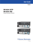
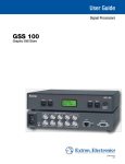
User Guide
Scalers and Scan Converters
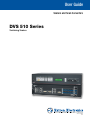
DVS 510 Series
Switching Scalers
68-1290-01 Rev. B
04 12
Safety Instructions • English
This symbol is intended to alert the user of important operating and maintenance (servicing) instructions in the literature provided with the equipment.
This symbol is intended to alert the user of the presence of uninsulated
dangerous voltage within the product’s enclosure that may present a risk of
electric shock.
Caution
Read Instructions • Read and understand all safety and operating instructions before using the equipment.
Retain Instructions • The safety instructions should be kept for future reference.
Follow Warnings • Follow all warnings and instructions marked on the equipment or in the user information.
Avoid Attachments • Do not use tools or attachments that are not recommended by the equipment
manufacturer because they may be hazardous.
Consignes de Sécurité • Français
Warning
Power sources • This equipment should be operated only from the power source indicated on the product. This
equipment is intended to be used with a main power system with a grounded (neutral) conductor. The third
(grounding) pin is a safety feature, do not attempt to bypass or disable it.
Power disconnection • To remove power from the equipment safely, remove all power cords from the rear of
the equipment, or the desktop power module (if detachable), or from the power source receptacle (wall plug).
Power cord protection • Power cords should be routed so that they are not likely to be stepped on or pinched
by items placed upon or against them.
Servicing • Refer all servicing to qualified service personnel. There are no user-serviceable parts inside. To prevent
the risk of shock, do not attempt to service this equipment yourself because opening or removing covers may
expose you to dangerous voltage or other hazards.
Slots and openings • If the equipment has slots or holes in the enclosure, these are provided to prevent
overheating of sensitive components inside. These openings must never be blocked by other objects.
Lithium battery • There is a danger of explosion if battery is incorrectly replaced. Replace it only with the
same or equivalent type recommended by the manufacturer. Dispose of used batteries according to the
manufacturer’s instructions.
Avertissement
Ce symbole sert à avertir l’utilisateur que la documentation fournie avec le
matériel contient des instructions importantes concernant l’exploitation et la
maintenance (réparation).
Alimentations • Ne faire fonctionner ce matériel qu’avec la source d’alimentation indiquée sur l’appareil. Ce
matériel doit être utilisé avec une alimentation principale comportant un fil de terre (neutre). Le troisième
contact (de mise à la terre) constitue un dispositif de sécurité : n’essayez pas de la contourner ni de la
désactiver.
Ce symbole sert à avertir l’utilisateur de la présence dans le boîtier
de l’appareil de tensions dangereuses non isolées posant des risques
d’électrocution.
Déconnexion de l’alimentation• Pour mettre le matériel hors tension sans danger, déconnectez tous les
cordons d’alimentation de l’arrière de l’appareil ou du module d’alimentation de bureau (s’il est amovible) ou
encore de la prise secteur.
Attention
Lire les instructions• Prendre connaissance de toutes les consignes de sécurité et d’exploitation avant
d’utiliser le matériel.
Conserver les instructions• Ranger les consignes de sécurité afin de pouvoir les consulter à l’avenir.
Respecter les avertissements • Observer tous les avertissements et consignes marqués sur le matériel ou
présentés dans la documentation utilisateur.
Eviter les pièces de fixation • Ne pas utiliser de pièces de fixation ni d’outils non recommandés par le
fabricant du matériel car cela risquerait de poser certains dangers.
Sicherheitsanleitungen • Deutsch
Protection du cordon d’alimentation • Acheminer les cordons d’alimentation de manière à ce que personne
ne risque de marcher dessus et à ce qu’ils ne soient pas écrasés ou pincés par des objets.
Réparation-maintenance • Faire exécuter toutes les interventions de réparation-maintenance par un
technicien qualifié. Aucun des éléments internes ne peut être réparé par l’utilisateur. Afin d’éviter tout danger
d’électrocution, l’utilisateur ne doit pas essayer de procéder lui-même à ces opérations car l’ouverture ou le
retrait des couvercles risquent de l’exposer à de hautes tensions et autres dangers.
Fentes et orifices • Si le boîtier de l’appareil comporte des fentes ou des orifices, ceux-ci servent à empêcher les
composants internes sensibles de surchauffer. Ces ouvertures ne doivent jamais être bloquées par des objets.
Lithium Batterie • Il a danger d’explosion s’ll y a remplacment incorrect de la batterie. Remplacer uniquement
avec une batterie du meme type ou d’un ype equivalent recommande par le constructeur. Mettre au reut les
batteries usagees conformement aux instructions du fabricant.
Vorsicht
Dieses Symbol soll dem Benutzer in der im Lieferumfang enthaltenen
Dokumentation besonders wichtige Hinweise zur Bedienung und Wartung
(Instandhaltung) geben.
Stromquellen • Dieses Gerät sollte nur über die auf dem Produkt angegebene Stromquelle betrieben werden.
Dieses Gerät wurde für eine Verwendung mit einer Hauptstromleitung mit einem geerdeten (neutralen) Leiter
konzipiert. Der dritte Kontakt ist für einen Erdanschluß, und stellt eine Sicherheitsfunktion dar. Diese sollte nicht
umgangen oder außer Betrieb gesetzt werden.
Dieses Symbol soll den Benutzer darauf aufmerksam machen, daß im Inneren
des Gehäuses dieses Produktes gefährliche Spannungen, die nicht isoliert sind
und die einen elektrischen Schock verursachen können, herrschen.
Stromunterbrechung • Um das Gerät auf sichere Weise vom Netz zu trennen, sollten Sie alle Netzkabel aus der
Rückseite des Gerätes, aus der externen Stomversorgung (falls dies möglich ist) oder aus der Wandsteckdose
ziehen.
Achtung
Lesen der Anleitungen • Bevor Sie das Gerät zum ersten Mal verwenden, sollten Sie alle Sicherheits-und
Bedienungsanleitungen genau durchlesen und verstehen.
Aufbewahren der Anleitungen • Die Hinweise zur elektrischen Sicherheit des Produktes sollten Sie
aufbewahren, damit Sie im Bedarfsfall darauf zurückgreifen können.
Befolgen der Warnhinweise • Befolgen Sie alle Warnhinweise und Anleitungen auf dem Gerät oder in der
Benutzerdokumentation.
Keine Zusatzgeräte • Verwenden Sie keine Werkzeuge oder Zusatzgeräte, die nicht ausdrücklich vom
Hersteller empfohlen wurden, da diese eine Gefahrenquelle darstellen können.
Schutz des Netzkabels • Netzkabel sollten stets so verlegt werden, daß sie nicht im Weg liegen und niemand
darauf treten kann oder Objekte darauf- oder unmittelbar dagegengestellt werden können.
Wartung • Alle Wartungsmaßnahmen sollten nur von qualifiziertem Servicepersonal durchgeführt werden.
Die internen Komponenten des Gerätes sind wartungsfrei. Zur Vermeidung eines elektrischen Schocks
versuchen Sie in keinem Fall, dieses Gerät selbst öffnen, da beim Entfernen der Abdeckungen die Gefahr eines
elektrischen Schlags und/oder andere Gefahren bestehen.
Schlitze und Öffnungen • Wenn das Gerät Schlitze oder Löcher im Gehäuse aufweist, dienen diese zur
Vermeidung einer Überhitzung der empfindlichen Teile im Inneren. Diese Öffnungen dürfen niemals von
anderen Objekten blockiert werden.
Litium-Batterie • Explosionsgefahr, falls die Batterie nicht richtig ersetzt wird. Ersetzen Sie verbrauchte Batterien
nur durch den gleichen oder einen vergleichbaren Batterietyp, der auch vom Hersteller empfohlen wird.
Entsorgen Sie verbrauchte Batterien bitte gemäß den Herstelleranweisungen.
Instrucciones de seguridad • Español
Este símbolo se utiliza para advertir al usuario sobre instrucciones importantes de operación y mantenimiento (o cambio de partes) que se desean
destacar en el contenido de la documentación suministrada con los equipos.
Este símbolo se utiliza para advertir al usuario sobre la presencia de elementos con voltaje peligroso sin protección aislante, que puedan encontrarse
dentro de la caja o alojamiento del producto, y que puedan representar
riesgo de electrocución.
Precaucion
Leer las instrucciones • Leer y analizar todas las instrucciones de operación y seguridad, antes de usar el
equipo.
Conservar las instrucciones • Conservar las instrucciones de seguridad para futura consulta.
Obedecer las advertencias • Todas las advertencias e instrucciones marcadas en el equipo o en la
documentación del usuario, deben ser obedecidas.
Evitar el uso de accesorios • No usar herramientas o accesorios que no sean especificamente
recomendados por el fabricante, ya que podrian implicar riesgos.
安全须知 • 中文
这个符号提示用户该设备用户手册中有重要的操作和维护说明。
这个符号警告用户该设备机壳内有暴露的危险电压,有触电危险。
注意
阅读说明书 • 用户使用该设备前必须阅读并理解所有安全和使用说明。
保存说明书 • 用户应保存安全说明书以备将来使用。
遵守警告 • 用户应遵守产品和用户指南上的所有安全和操作说明。
避免追加 • 不要使用该产品厂商没有推荐的工具或追加设备,以避免危险。
Advertencia
Alimentación eléctrica • Este equipo debe conectarse únicamente a la fuente/tipo de alimentación eléctrica
indicada en el mismo. La alimentación eléctrica de este equipo debe provenir de un sistema de distribución
general con conductor neutro a tierra. La tercera pata (puesta a tierra) es una medida de seguridad, no
puentearia ni eliminaria.
Desconexión de alimentación eléctrica • Para desconectar con seguridad la acometida de alimentación
eléctrica al equipo, desenchufar todos los cables de alimentación en el panel trasero del equipo, o desenchufar
el módulo de alimentación (si fuera independiente), o desenchufar el cable del receptáculo de la pared.
Protección del cables de alimentación • Los cables de alimentación eléctrica se deben instalar en lugares
donde no sean pisados ni apretados por objetos que se puedan apoyar sobre ellos.
Reparaciones/mantenimiento • Solicitar siempre los servicios técnicos de personal calificado. En el interior no
hay partes a las que el usuario deba acceder. Para evitar riesgo de electrocución, no intentar personalmente la
reparación/mantenimiento de este equipo, ya que al abrir o extraer las tapas puede quedar expuesto a voltajes
peligrosos u otros riesgos.
Ranuras y aberturas • Si el equipo posee ranuras o orificios en su caja/alojamiento, es para evitar el
sobrecalientamiento de componentes internos sensibles. Estas aberturas nunca se deben obstruir con otros
objetos.
Batería de litio • Existe riesgo de explosión si esta batería se coloca en la posición incorrecta. Cambiar esta
batería únicamente con el mismo tipo (o su equivalente) recomendado por el fabricante. Desachar las baterías
usadas siguiendo las instrucciones del fabricante.
警告
电源 • 该设备只能使用产品上标明的电源。 设备必须使用有地线的供电系统供电。 第三条线
(地线)是安全设施,不能不用或跳过 。
拔掉电源 • 为安全地从设备拔掉电源,请拔掉所有设备后或桌面电源的电源线,或任何接到市
电系统的电源线。
电源线保护 • 妥善布线, 避免被踩踏,或重物挤压。
维护 • 所有维修必须由认证的维修人员进行。 设备内部没有用户可以更换的零件。为避免出现
触电危险不要自己试图打开设备盖子维修该设备。
通风孔 • 有些设备机壳上有通风槽或孔,它们是用来防止机内敏感元件过热。 不要用任何东
西挡住通风孔。
锂电池 • 不正确的更换电池会有爆炸的危险。必须使用与厂家推荐的相同或相近型号的电池。
按照生产厂的建议处理废弃电池。
ii
FCC Class A Notice
This equipment has been tested and found to comply with the limits for a Class A digital device, pursuant to part 15
of the FCC Rules. Operation is subject to the following two conditions:
1. This device may not cause harmful interference.
2. This device must accept any interference received, including interference that may cause undesired operation.
The Class A limits are designed to provide reasonable protection against harmful interference when the equipment is
operated in a commercial environment. This equipment generates, uses, and can radiate radio frequency energy and,
if not installed and used in accordance with the instruction manual, may cause harmful interference to radio communications. Operation of this equipment in a residential area is likely to cause harmful interference, in which case the
user will be required to correct the interference at his own expense.
NOTE: This unit was tested with shielded cables on the peripheral devices. Shielded cables must be used with
the unit to ensure compliance with FCC emissions limits.
For more information on safety guidelines, regulatory compliances, EMI/EMF compliance, accessibility, and
related topics, click here.
iii
Conventions Used in this Guide
In this user guide, the following are used:
CAUTION: A caution indicates a potential hazard to equipment or data.
NOTE: A note draws attention to important information.
TIP: A tip provides a suggestion to make working with the application easier.
WARNING: A warning warns of things or actions that might cause injury, death, or
other severe consequences.
Commands are written in the fonts shown here:
^AR Merge Scene,,Op1 scene 1,1 ^B 51 ^W^C
[01] R 0004 00300 00400 00800 00600 [02] 35 [17] [03]
E X! *X1&* X2)* X2#* X2! CE}
NOTE: For commands and examples of computer or device responses mentioned in this
guide, the character “0” is used for the number zero and “O” represents the
capital letter “o.”
Computer responses and directory paths that do not have variables are written in the font
shown here:
Reply from 208.132.180.48: bytes=32 times=2ms TTL=32
C:\Program Files\Extron
Variables are written in slanted form as shown here:
ping xxx.xxx.xxx.xxx —t
SOH R Data STX Command ETB ETX
Selectable items, such as menu names, menu options, buttons, tabs, and field names are
written in the font shown here:
From the File menu, select New.
Click the OK button.
Copyright
© 2012 Extron Electronics. All rights reserved.
Trademarks
All trademarks mentioned in this manual are the properties of their respective owners.
iv
Contents
Introduction............................................................ 1
About this Guide................................................. 1
About the DVS 510 Series Scalers........................ 1
Features............................................................... 2
Controlling the DVS 510 Series............................ 4
Application Diagram............................................ 5
Installation............................................................... 6
Installation Overview............................................ 6
Rear Panel........................................................... 7
Connecting to the RS-232 Config Port
(Front Panel)..................................................... 11
Wiring the Amplified Audio Port
(DVS 510 SA Only)............................................ 12
Operation............................................................... 14
Front Panel........................................................ 14
Powering On..................................................... 17
Picture-in-Picture (PIP) Mode.............................. 18
Enabling PIP Mode......................................... 19
Changing the PIP Input.................................. 19
Using the PIP Swap Feature............................ 19
Menus on the LCD Screen.................................. 20
Menu System Overview.................................. 20
User Presets Menu......................................... 22
Input Configuration Menu............................. 23
Output Configuration Menu.......................... 26
Audio Configuration Menu............................ 28
Advanced Configuration Menu...................... 29
View Comm Settings Menu .......................... 34
Edit Comm Settings Menu............................. 34
Exiting the Menu System................................ 36
Picture Controls................................................. 36
Adjusting the Picture Controls........................ 37
Picture Controls Summary.............................. 37
Input Presets...................................................... 38
Audio Functions................................................. 38
Volume Control............................................. 39
Audio or Video Breakaway............................. 40
Resetting .......................................................... 40
Front Panel Lockout (Executive Mode)................ 42
Additional Features............................................ 42
Freeze............................................................ 42
Power Save Modes......................................... 42
Output Sync Mute......................................... 43
Overscan Mode.............................................. 43
Using the Optional IR 904 Remote Control......... 43
Locking IR Remote Control Access................. 44
Installing Batteries in the IR 904 Remote
Control......................................................... 44
Buttons on the IR 904 Remote Control........... 44
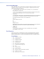
Remote Configuration and Control................. 47
Serial Ports......................................................... 47
Ethernet Port..................................................... 47
Ethernet Cable............................................... 47
IP Address...................................................... 48
Establishing an Ethernet Connection Using
TCP............................................................... 48
Connection Timeouts..................................... 48
Using SIS Commands......................................... 48
Scaler-initiated Messages............................... 49
Error Responses............................................. 49
Error Response References............................. 50
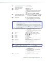
Using the Command and Response Tables..... 50
Symbol Definitions for DVS 510 Series SIS
Commands................................................... 51
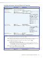
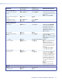
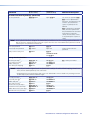
Command and Response Table for
DVS 510 Series SIS Commands..................... 55
Symbol Definitions for IP-specific SIS
Commands................................................... 67
Command and Response Table for
IP-Specific SIS Commands............................. 70
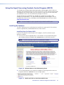
Using the Signal Processing Products Control
Program (SPPCP)............................................... 78
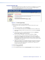
Installing the Software................................... 78
Starting the Software..................................... 80
Accessing the Help File................................... 81
Updating the Firmware Using SPPCP.............. 82
Accessing the Web Pages................................... 85
Special Characters............................................. 86
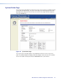
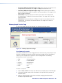
System Status Page............................................ 87
DVS 510 Series • Contents
v
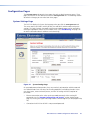
Configuration Pages.......................................... 88
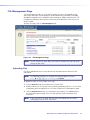
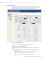
System Settings Page..................................... 88
Passwords Page............................................. 94
Firmware Upgrade page................................. 95
File Management Page...................................... 97
Uploading Files.............................................. 97
Adding a Directory......................................... 98
Other File Management Activities................... 98
Control Pages.................................................... 98
User Control Page.......................................... 99
Memory/Input Presets Page.......................... 102
PIP Setup Page............................................. 104
Reference Information...................................... 107
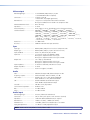
Specifications................................................... 107
Part Numbers................................................... 110
Included Parts.............................................. 110
Optional Accessories.................................... 110
Mounting the DVS 510 Scaler.......................... 111
Rack Mounting............................................ 111
Tabletop Use................................................ 112
Button Labels................................................... 112
Replacing Button Labels............................... 112
Creating Labels Using the Button Label
Generator................................................... 113
Blank Button Labels..................................... 115
IP Addressing................................................... 116
What is an IP Address?................................. 116
Choosing IP Addresses................................. 116
Subnet Mask................................................ 117
Pinging for the IP Address............................ 117
Connecting as a Telnet Client....................... 118
Subnetting, a Primer.................................... 120
DVS 510 Series • Contents
vi
Introduction
This section gives an overview of the DVS 510 and DVS 510 SA scalers. Topics include:
•
About this Guide
•
About the DVS 510 Series Scalers
•
Features
•
Controlling the DVS 510 Series
•
Application Diagram
About this Guide
This guide contains information about the Extron DVS 510 Series of switching scalers
with instructions for experienced installers on how to install, configure, and operate the
equipment.
In this guide, the terms “DVS,” “DVS 510,” and “scaler” are used interchangeably to refer
to DVS 510 and the DVS 510 SA scalers.
About the DVS 510 Series Scalers
The Extron DVS 510 Series scalers are 10-input, multi-format presentation switching scalers
that accept and scale DVI, RGB, YUVp/HDTV, YUVi, S-video, and composite video signals to
a common, high resolution output rate. With simultaneous DVI and two analog RGB/YUV
outputs, the DVS 510 can integrate analog and digital video devices, and HDCP compliance
enables integration of Blu-ray Disc players and cable or satellite HD receivers. The DVS 510
also offers flexible control options, including front panel controls, Ethernet, RS-232 or
RS-422, and infrared (IR).
The DVS 510 also includes 10-input stereo audio switching to accompany incoming video
sources. Gain and attenuation adjustment is provided for each input, and the DVS 510
provides master volume control on the front panel. Also included are bass and treble
controls, as well as integrated audio delay to maintain audio sync with the processed video
output.
The DVS 510 is available in two configurations: the standard DVS 510, which offers fixed
and variable line level audio outputs, and the DVS 510 SA, which adds an integrated stereo
amplifier with 25 watts rms output per channel into 4 or 8 ohms.
DVS 510 Series • Introduction
1
Features
The DVS 510 provides the following features:
•
Video upscaling and downscaling — DVI, RGB computer video, high definition video,
and standard definition video sources can all be scaled to the desired output resolution.
The DVS 510 scaling engine provides high quality upscaling and downscaling of high
resolution computer video signals.
•
High Performance Video Processing — A high performance 30-bit scaling engine is
able to scale standard definition video, HDTV, and RGB signals up or down in resolution.
It accepts computer video signals up to 1920x1200 and HDTV 1080p/60. It outputs
DVI and analog RGB or component video at selectable output rates from 640x480 to
1920x1200 resolution and HDTV rates of up to 1080p/60.
•
EDID Minder® — The Extron EDID Minder automatically manages the Extended Display
Identification Data (EDID) for all the DVI and VGA input sources. By default, VGA and
DVI input EDIDs match the current output resolution of the scaler. Also available is a user
assigned mode, which allows pre-stored EDID, based on a user selected resolution, to be
manually assigned to the sources. By maintaining continuous EDID communication with
all sources, EDID Minder ensures that all DVI and VGA sources power up properly and
maintain their video outputs whether or not they are actively connected to the display
device through the scaler outputs.
•
Inputs — The DVS 510 has two composite video inputs on BNC connectors, two
S-video inputs on 4-pin mini DIN connectors, two RGB/YUV inputs on 15-pin HD
connectors, and two digital and two analog RGB/YUV inputs on DVI-I connectors. Stereo
balanced and unbalanced audio for each input is provided on 3.5 mm, 5-pole captive
screw connectors
•
Outputs — The DVS 510 has a scaled DVI-D video output on a DVI-I connector, two
scaled RGB/YUV outputs on 15-pin HD connectors, and two audio outputs (one fixed
and one variable) providing balanced and unbalanced stereo audio on 3.5 mm 5-pole
captive screw connectors. The DVS 510 SA also has an amplified output on a 5 mm,
4-pole captive screw connector.
•
Simultaneous DVI and analog RGB or HD component video outputs — A DVI-D
and two analog RGB/YUV outputs are provided for driving up to three display devices.
•
Selectable output rates — Available output rates include computer video up to
1920x1200, HDTV rates up to 1080p/60, and 2048x1080.
•
HDCP compliance — The DVS 510 fully supports HDCP-encrypted signals.
•
Active HDCP verification — The DVS 510 provides real-time verification of HDCP
status for each DVI input and output. This allows for quick signal and HDCP verification
through RS-232/RS-422 or Ethernet.
•
HDCP Visual Confirmation — The DVS 510 outputs a full-screen green signal and an
on-screen message when an HDCP compliant source is routed to a non-HDCP compliant
display, providing immediate visual confirmation that protected content cannot be
viewed on the selected display.
•
Image freeze control — A live image can be frozen through RS-232 or RS-422 serial
control and through Ethernet control.
•
Auto-Image™ setup — Enables the DVS 510 to automatically analyze the incoming
video signal for each input and adjust sizing, centering, and filtering to optimize image
quality. This can save time and effort in fine tuning displayed images.
•
Auto memories — Enables the DVS 510 to store size, position, and picture settings
based on the incoming signal. When the same signal is detected again, these image
settings are recalled from memory.
DVS 510 Series • Introduction
2
•
PIP (picture-in-picture) — Allows a video source to be displayed within a high
resolution image, or vice versa. Audio switching can be set to follow either the main
or PIP window.
•
Glitch-free switching — Switching between sources occurs without distortions or
glitches with selectable cut or fade-to-black transitions.
•
Customizable front panel control buttons — The tri-colored, backlit pushbuttons
on the front panel can be custom-labeled.
•
Power Save Mode — The DVS 510 can be set to mute video and sync output to
the display device when no active input signal is detected. This allows the projector
or flat-panel display to automatically enter into standby mode to save energy and
enhance lamp or panel life.
•
HDMI signals support — When used with optional Extron HDMI-DVI adapters, the
DVI inputs and output on the DVS 510 are compatible with HDMI. The DVS 510 fully
passes audio and auxiliary data as part of the HDMI signal, ensuring audio and video
compatibility with downstream HDMI-equipped devices.
•
Audio switching and output volume control — The DVS 510 features audio
switching for 10 stereo balanced or unbalanced input sources, and provides master
volume control and muting as well as bass and treble controls. Fixed and variable line
level outputs are available, and each output can be balanced or unbalanced. Stereo
input signals can be output as dual mono.
•
Audio or video breakaway — Lets you break an audio signal away from its
corresponding video signal and route it to the audio outputs, allowing the audio
channels to be operated as a separate scaler.
•
Integrated audio delay — Delays the audio output automatically to compensate for
latency introduced by the video processing.
•
Amplifier (DVS 510 SA only) — The DVS 510 SA has a stereo power amplifier
with 25 watts rms per channel into 4 or 8 ohms. The Class D amplifier design
includes CDRS™ – Class D Ripple Suppression, an Extron patented technology that
provides a smooth, clean audio waveform and an improvement in signal fidelity over
conventional Class D amplifier designs. CDRS eliminates the high frequency switching
ripple characteristic of Class D amplifiers, a source of RF emissions that can interfere
with sensitive AV equipment such as wireless microphones.
The DVS 510 SA includes technology for the integrated amplifier that detects the
onset of clipping by comparing input and output signals. Gain is reduced with a slow
attack and fast release to eliminate clipping and protects the speakers from clipping
distortion.
•
Picture controls — Brightness, contrast, color, tint, detail, horizontal and vertical
positioning, sizing, and zoom can be set. 16 user memory presets are available for
each input to store all image settings.
•
Automatic 3:2 and 2:2 pulldown detection — Advanced film mode processing
techniques help maximize image detail and sharpness for NTSC, PAL, and HDTV 1080i
sources that originated from film.
•
Motion adaptive 1080i deinterlacing — High performance deinterlacing is
provided for 1080i signals from HD sources, including cable or satellite set-top devices,
delivering optimized image quality through advanced motion compensation.
•
Aspect ratio control — The output can be designated to meet a specific aspect ratio
requirement so that the image fills the screen, or is displayed with compensation for
the native aspect ratio of the source.
•
Quad standard video decoding — A digital, four-line adaptive comb filter decodes
NTSC 3.58, NTSC 4.43, PAL, and SECAM for integration into systems worldwide.
DVS 510 Series • Introduction
3
•
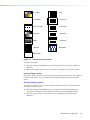
Test patterns — 12 test patterns are provided for calibration and setup, including a
crop pattern, crosshatch, 16 bar grayscale, color bars, alternating pixels, ramp, white
field, 4 x 4 crosshatch, and four aspect ratio patterns (1.33, 1.78, 1.85, and 2.35).
•
Front panel security lockout (executive mode) — When enabled, locks out all front
panel functions except for input selection (all functions remain available through RS-232,
RS-422, or IR remote control).
•
Optional IR remote control — The optional Extron IR 904 handheld remote control
provides an additional method of input source switching, picture-in-picture, and direct
access to picture adjustments.
•
Ethernet monitoring and control — The DVS 510 can be controlled and proactively
monitored over a LAN, WAN, or the Internet. Embedded web pages are included for
such common functions as input switching, volume control, and system configuration.
•
RS-232 and RS-422 control — The DVS 510 can be controlled and configured via
Simple Instruction Set (SIS™) commands, a set of basic ASCII code commands that allow
for quick and easy programming via RS-232 or RS-422.
•
Windows-based configuration and control software — The Signal Processing
Products Control Program (SPPCP) can be used to configure and control the DVS 510 via
RS-232, RS-422, or Ethernet.
•
Rack-mountable 2U, full rack width metal enclosure
•
Internal universal power supply — The 100-240 VAC, 50-60 Hz, international power
supply provides worldwide power compatibility.
Controlling the DVS 510 Series
You can control the DVS 510 and the DVS 510 SA using one or more of the following
methods:
•
The front panel controls include back-lit buttons, a Volume Control knob, and rotary
Adjustment encoders.
•
A computer, a touch screen panel, or any other device that can send and receive serial
communications through the RS-232/RS-422 or Ethernet port enables the following
controls:
•
•
The Extron Simple Instruction Set (SIS) is a set of simple keystroke commands that
can be used with any RS-232 or RS-422 device.
•
The Extron Windows-based control software provides a graphical interface for
controlling the scaler from a computer.
•
The embedded web pages enable HTML control of the DVS from a computer.
The optional IR 904 remote control, part number 70-767-01, replicates most of the front
panel controls
DVS 510 Series • Introduction
4
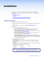
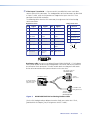
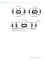
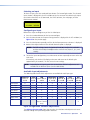
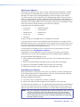
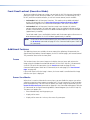
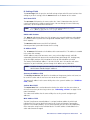
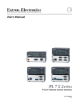
Application Diagram
The following diagram shows an example of a DVS 510 SA application.
Extron
DVS 510 SA
Extron
SI 28
Scaling Presentation
Switcher
Surface-mount
Speakers
UT
TP
D OU
IFIE
PL
AM
TouchLink™
Control
System
9
R
7
L
N
N
A
U
D
I
O
Y,
B/
V
I
D
E
O
Y,
B-
Y
R-
I-D
DV
I
N
P
U
T
R
®
SE
100
RE
INPUT
IR
COM
RX
LA
IPL
TX
250
LINK
3
ACT
1
3
4
3
2
1
4
2
1
2
R
L
R
RELAY
1
N
L
R
4
2
TCP/IP
E
LIN
T
L
R
6
L
R
L
R
L
R
8
L
R
SCREE
DOWN
MP
EA
L
R
3
L
PR
10
L
1
O
U
T
P
U
T
R
5
P
PC
Y
SCREE
UP
R
A
U
D
I
O
VCR
DVD
DOC
CAM
LAPTO
ON
OFF
DISPLA
MUTE
4
2
3
-232
RS
L
R
L
RG
Y,
B/
Y,
B-
Y
R-
RG
O
U
T
P
U
T
I-I
DV
0
5
Y,
B/
Y,
B-
9/1
Y
R-
RG
I-I
DV
3
YC
1
7/8
VID
V
I
D
E
O
60
50/
0V
-24
100
Document
Camera
Hz
I
N
P
U
T
Y,
B/
RG
Y,
B6
Y
R-
YC
VID
4
2
Flat Panel
Display
X
3A
MA
Projector
VCR/DVD
DVD
Player
Laptop
DVI Output
PC
Blu-ray
Player
PC
Figure 1.
Connection Diagram for a DVS 510 SA
DVS 510 Series • Introduction
5
Installation
This section gives an overview of the steps to installing the DVS 510. It also provides a
description of the rear panel connectors and instructions for cabling. The following topics
are discussed:
•
Installation Overview
•
Rear Panel
•
Connecting to the RS-232 Config Port (Front Panel)
•
Wiring the Amplified Audio Ports (DVS 510 SA Only)
Installation Overview
Follow these steps to install and set up the DVS 510:
1. Disconnect power from the scaler and turn off all other devices that will be connected
to it.
2. (Optional) Mount the unit in a rack (see “Mounting the DVS 510 Scaler” on
page 111).
3. Connect video and audio sources and outputs:
•
Connect video input devices to the applicable connectors in the Video Input
section (b through e on the rear panel diagram on the next page).
•
Connect video output devices to the appropriate connectors in the Video Output
section (f and g on the rear panel diagram).
•
Connect audio input devices to the appropriate captive screw connectors in the
Audio Input section (h on the rear panel diagram).
•
Connect audio output devices to the 5-pole Variable (j) and Fixed (k) captive
screw audio connectors in the Audio Output section as desired. On the DVS 510 SA,
you can connect speakers or another output device to the internal amplifier through
the 4-pole Amplified connector (i).
4. Connect control devices as desired:
LAN Ethernet port — Connect the DVS to an Ethernet LAN or WAN via this RJ-45
connector (n) to control the scaler from a remote location, using an Internet browser
on a computer.
RS232 port — For serial RS-232 or RS-422 control, connect a host computer or control
system to the DVS via the 9-pin D-sub connector (o).
Protocol (default values) for this port is:
• 9600 baud
• 1 stop bit • 8 data bits • no flow control
• no parity
NOTE: See the “Remote Configuration and Control” section, beginning on
page 47, for definitions of the SIS commands and for instructions for
installing and starting the Signal Processing Products Control Program (SPPCP).
DVS 510 Series • Installation
6
5. Connect power to the DVS by plugging a standard IEC power cord (provided) from a
100 to 240 VAC, 50-60 Hz AC power source into the power receptacle (a).
6. Configure the DVS 510 using the SPPCP (see the control program help file), SIS
commands (see the “Remote Configuration and Control” section, beginning on
page 47), the web pages (see the “HTML Configuration and Control” section,
beginning on page 85), or any combination of these methods.
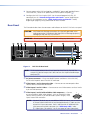
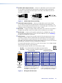
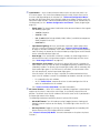
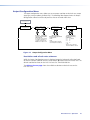
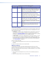
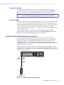
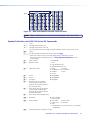
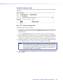
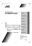
Rear Panel
The illustration below shows the connectors and indicators on the DVS 510 Series rear panel.
CAUTION: Use Electrostatic discharge precautions (be electrically grounded) when
making connections. Electrostatic discharge (ESD) can damage equipment,
although you may not feel, see, or hear it.
WARNING: Remove power from the system before making any connections.
1
2
5
4
3
6
7
9
8
AMPLIFIED
1
V
I
D
E
O
100-240V
50-60 Hz
2A MAX
3
VID
I
N
P
U
T
2
5
YC
YC
VID
4
A
U
D
I
O
RGB/R-Y, Y, B-Y
RGB/R-Y, Y, B-Y
6
DVI-I
7/8
DVI-I
9/10
V
I
D
E
O
RGB/R-Y, Y, B-Y
O
U
T
P
U
T
RGB/R-Y, Y, B-Y
A
U
D
I
O
DVI-D
I
N
P
U
T
1
L
3
R
L
R
L
2
L
5
R
L
R
L
4
7
R
L
R
L
6
9
R
L
R
L
8
O
U
T
P
U
T
R
10
R
L
R
VARIABLE
L
10
R
FIXED
L
11
R
12
RS232
15
Figure 2.
LAN
RESET
14 13
DVS 510 SA Rear Panel
NOTE: The illustration above shows the rear panel of a DVS 510 SA. The DVS 510
rear panel is identical except that it does not have the Amplified audio output
connector (i).
a AC power connector — Plug a standard IEC power cord from a 100 to 240 VAC,
50 Hz or 60 Hz power source into this IEC connector.
b Video inputs 1 and 2: Composite video — Connect one or two composite video
sources to these female BNC connectors.
c Video inputs 3 and 4: S-video — Connect one or two S-video sources to these female
4-pin mini-DIN connectors.
d Video inputs 5 and 6: buffered RGB or YUV component — Connect
one or two RGBHV, RGBS, RGsB, RGBcvS, YUVi, or YUVp/HDTV video
sources to these female 15-pin HD connectors (shown at right). These
inputs feature EDID emulation.
3
2
14
1
13
NOTE: (Optional) To obtain one or two additional RGB/YUV inputs, you can connect
an Extron DVIIM-VGAF/DVIIF DVI and Analog Breakaway (Y) cable to either
or both DVI-I input connectors. Each Y cable provides an additional RGB
VGA connector and DVI-I connector (see ”Breakaway cable” under
e “Video inputs 7/8 and 9/10” on the next page for more information).
DVS 510 Series • Installation
7
e Video inputs 7/8 and 9/10 — Connect two DVI, two RGB/YUV, or one each video
sources to these DVI-I connectors. The analog portions of these connectors are identified
as inputs 7 and 9, while the DVI portions are recognized as inputs 8 and 10. These
connectors feature EDID emulation.
The following tables show the DVI-I connector pin assignments for DVI and analog
source connection.
Digital Connections
Analog Connections
Pin
Signal
Pin
Signal
Pin
Signal
1
TMDS data 2–
9
TMDS data 1–
17
TMDS data 0–
C1 Red signal
2
TMDS data 2+ 10 TMDS data 1+
18
TMDS data 0+
C2
3
TMDS data
2/4 shield
11 TMDS data 1/3
shield
19
TMDS data 0/5
shield
C3 Blue signal
4
Not used
12 Not used
20
Not used
5
Not used
13 Not used
21
Not used
6
DDC clock
14 +5 V power
22
TMDS clock
shield
C5
7
DDC data
15 Ground
23
TMDS clock+
C3
8
Not used
16 Hot plug
detect
24
TMDS clock–
9
1
8
17
24
Function
Pin
Green signal
C4 Horizontal sync
C5
Ground
C2
C1
C4
Breakaway cable: You can use an optional Extron DVIIM-VGAF/DVIIF “Y” DVI adapter
cable (shown below) to connect one analog RGB or YUV source and one DVI source to
one or both of these connectors. This cable enables both an analog and a DVI source
device to be connected to these ports and active at the same time.
DVI-I Female Connector
FOR DIGITAL ONLY
DVI-I Male Connector
To a DVI
Input Source
To DVS 510 Female
DVI-I Input Connector
(Input 7/8 or 9/10)
Extron
To an RGB or YUV
Analog Input Source
15-pin HD
Female Connector
FOR ANALOG ONLY
Figure 3.
DVIIM-VGAF/DVIIF DVI and Analog Breakout Cable
(See the DVI Analog Breakout Adapter Instruction Card, part number 68-1172-01,
[provided with the adapter], for pin assignments for this Y cable.)
DVS 510 Series • Installation
8
f RGB/YUV output connectors — Connect cables from RGB (RGBHV, RGBS, RGsB) or
YUVp/HD component (R-Y, Y, B-Y) display devices to these female 15-pin HD connectors
for scaled RGB or component video output. The output can be scaled to 69 different
output rates (see the resolution and refresh rates table on page 27).
NOTE: Outputs are buffered and can be connected simultaneously to two different
displays. The sync and video formats are the same for all outputs.
g DVI-I output connector — Connect a digital (DVI-D) display device to this DVI-I
connector for a scaled DVI output (analog output is not available on this connector). The
figure below shows the pin assignments for the DVI output connector.
Pin
Signal
Pin
Signal
Pin
Signal
1
TMDS data 2–
9
TMDS data 1–
17
TMDS data 0–
2
TMDS data 2+ 10 TMDS data 1+
18
TMDS data 0+
3
Ground (2/4 )
11 Ground (1/3)
19
Ground (0/5)
4
Not used
12 Not used
20
Not used
5
Not used
13 Not used
21
Not used
6
DDC clock
14 +5 V power
22
Ground (clock)
7
DDC data
15 Ground (for 5 V) 23
TMDS clock+
8
Not used
16 Hot plug detect
TMDS clock–
24
9
1
8
17
24
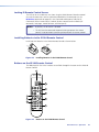
h Audio input connectors — Connect up to 10 audio input devices to these female
3.5 mm 5-pole captive screw connectors for balanced or unbalanced audio input. (One
audio input is provided for each video input.)
Figure 4.
R
R
Unbalanced Stereo Input
Tip
Ring
Sleeves
Tip
Ring
L
L
Tip
Sleeve
Tip
Sleeve
Balanced Stereo Input
Do not tin the wires!
Audio Input Connector Wiring
i Amplified audio output connector (DVS 510 SA only) — This 4-pole, 5 mm captive
screw connector enables you to connect a set of speakers or another output device to
the DVS 510 SA internal amplifier for amplified output.
All right channel input signals are mixed and summed to produce a single, right channel
output; likewise, all left channel input signals are mixed and summed to produce a
single, left channel output.
If Stereo is selected for the output type, the output is stereo; if Dual Mono is selected,
the right and left channels are mixed and summed for a dual mono output.
With an 8 ohm load, the amplifier produces up to 8 watts per channel. With a 4 ohm
load, the amplifier produces up to 25 watts per channel.
(See “Wiring the Amplified Audio Port [DVS 510 SA Only]”on page 12 for
information on connecting speakers to this port.)
DVS 510 Series • Installation
9
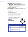
j Variable audio output connector — Connect an audio device to this female 5-pole
3.5 mm captive screw connector for balanced or unbalanced variable audio output.
This output is affected by tone control, gain, attenuation, and audio delay. Wire the
connector as shown below.
No Ground Here
L
L
R
Tip
Sleeves
Tip
Do not tin the wires!
R
Tip
Ring
Sleeves
Tip
Ring
No Ground Here
Balanced Audio Output
Figure 5.
Unbalanced Audio Output
Audio Output Connector Wiring
k Fixed audio output connector — Connect an audio device to this female 5-pole
3.5 mm captive screw connector for balanced or unbalanced fixed audio output. This
output is not affected by tone control; however, it is affected by gain, attenuation, and
audio delay. Wire the connector as shown in figure 5, above.
l Reset LED — This green LED lights steadily while power is on. While the reset button is
being pressed and held, it blinks the number of times to indicate the reset mode.
m Reset button — Using a small screwdriver, pointed stylus, or ballpoint pen, press this
recessed button for manual resets. The unit has four modes of reset (see “Resetting”
on page 40 for additional information).
n LAN connector — Plug an Ethernet cable into this RJ-45 jack to connect the unit to
a computer network. Ethernet control allows you to configure and control the scaler
from a remote location using SIS commands, the SPPCP software, or the embedded
web pages. When connected to an Ethernet LAN or WAN, the DVS can be accessed and
operated from a computer running a standard Internet browser.
Use a patch cable to connect the DVS to a switch, hub, or router; use a straight-through
cable to connect it directly to your computer.
ETHERNET
This connector contains two LEDs (see the illustration at right):
•
Act LED — This amber LED blinks to indicate LAN signal activity.
•
Link LED — This green LED lights steadily to indicate a LAN connection.
Crossover Cable
Pins:
12345678
Pin
Insert Twisted
Pair Wires
RJ-45
Connector
Figure 6.
End 1
Wire color
End 2
Wire color
ACT LINK
Straight-through Cable
Pin
End 1
Wire color
End 2
Wire color
1 White-green
White-orange
1 White-orange
White-orange
2 Green
Orange
2
Orange
Orange
3 White-orange
White-green
3 White-green
White-green
4 Blue
Blue
4 Blue
Blue
5 White-blue
White-blue
5 White-blue
White-blue
6 Orange
7 White-brown
Green
White-brown
6 Green
7 White-brown
Green
White-brown
8 Brown
Brown
8 Brown
Brown
T568B
T568A
A cable that is wired as T568A at one end
and T568B at the other (Tx and Rx pairs
reversed) is a "crossover" cable.
T568B
T568B
A cable that is wired the same at both ends
is called a "straight-through" cable, because
no pin or pair assignments are swapped.
Wiring the LAN Connector
DVS 510 Series • Installation
10
o RS232 connector — This female 9-pin DB-9 connector provides for RS-232 or RS-422
remote communication. Connect a host computer or control system to this connector
for serial control of the DVS by Simple Instruction Set (SIS) commands (see the “Remote
Configuration and Control” section, beginning on page 47) or by the SPPCP software
(see the control program help file).
The default protocol for this port is 9600 baud, 1 stop bit, no parity, and no flow
control. The figure below shows the pin assignments for the DB-9 connector.
5
1
9
6
RS232
Figure 7.
Pin
RS-232 Function
1
2
3
4
5
6
7
8
9
–
Tx
Rx
–
Gnd
–
–
–
–
Description
No connection
Transmit data
Receive data
No connection
Signal ground
No connection
No connection
No connection
No connection
Pin Assignments for the RS-232 Port
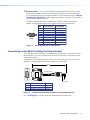
Connecting to the RS-232 Config Port (Front Panel)
The Config port on the front panel is an additional RS-232 connector. A host device can be
connected to this 2.5 mm TRS connector for serial RS-232 control, as an alternative to the
rear panel RS232 port.
An optional 2.5 mm cable (part number 70-335-01) can be used to connect the DVS to a
computer. The figure below shows the pin assignments for this cable.
6 feet
(1.8 m)
1
Part #70-335-01
6
9
5
Tip
Ring
Sleeve (Gnd)
9-pin D
Connection
TRS Plug
Pin 2
Pin 3
Pin 5
Computer Rx line
Computer Tx line
Computer signal ground
Tip
Ring
Sleeve
Figure 8.
Optional 2.5 mm Connector Cable for the Configuration Port
(See “h Config port“ on page 16 for more information on this connector.)
DVS 510 Series • Installation
11
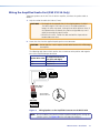
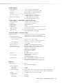
Wiring the Amplified Audio Port (DVS 510 SA Only)
To connect speakers to the DVS 510 SA built-in amplifier, terminate the speaker cable as
follows:
1. Strip the end of the cable 3/16 inches (5 mm).
CAUTIONS: • The length of the exposed wires in the stripping process is critical.
The ideal length is 3/16 inches (5 mm). If the exposed portion is
longer, the wires may touch, causing a short circuit between them. If
the exposed wires are shorter, they can be easily pulled out, even if
tightly fastened by the captive screws.
• Do not tin the wires. Tinned wire does not hold its shape and can
become loose over time.
2. Secure the wires into the supplied 4-pole captive screw connector.
CAUTION: Do not short the + and - outputs to each other because this will damage
the amplifier.
The following table shows which speaker wires to connect to the positive and negative
pins of the Amplified output connector.
Speaker Wire Color
To Amplified Connector
Pins (Left and Right)
Red
Positive (+)
Black
Negative (-)
Speaker 1
Speaker 2
Audio Output
to Speakers
4-pole Captive
Screw Connector
AMPLIFIED
4/8
Ohms
L
R
DVS 510 SA Rear Panel
Figure 9.
Wiring Speakers to the Amplified Connector on the DVS 510 SA
NOTE: Be sure to observe the correct speaker impedance loading when setting up a
speaker system. (See figure 10 on the next page for examples.)
DVS 510 Series • Installation
12
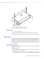
Fig 10 Connection examples
AMPLIFIED OUTPUTS
AMPLIFIED OUTPUTS
8 Ohms
Stereo L+
L
8 Ohms
Stereo R+
Mono +
Stereo R–
Mono –
R
Stereo L–
Mono +
L
8 Ohm Load
Mono –
8 Ohm Load
Dual Mono Connection
Stereo Connection
AMPLIFIED OUTPUTS
4/8 Ohms
Mono +
or
Stereo L+
8 ohms
4 Ohm Total Load
Two 8 ohm speakers
wired in parallel
equal a 4 ohm load.
Mono +
or
Stereo R+
8 ohms
8 ohms
Mono –
or
Stereo L-
R
L
R
Mono –
or
Stereo R-
8 ohms
4 Ohm Total Load
Figure 10. Speaker Connection Examples
DVS 510 Series • Installation
13
Operation
This section discusses the functions available through the front panel to set up and operate
the DVS 510 or DVS 510 SA. Topics include:
•
Front Panel
•
Powering On
•
Picture-in-Picture (PIP) Mode
•
Menus on the LCD Screen
•
Picture Controls
•
Input Presets
•
Audio Functions
•
Resetting
•
Front Panel Lockout (Executive Modes)
•
Additional Features
•
Using the Optional IR 904 Remote Control
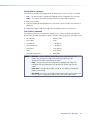
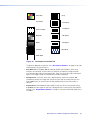
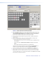
Front Panel
1
INPUTS
9
IR
CONFIG
3
2
PIP
1
2
3
4
5
PIP
ON/OFF
6
7
8
9
10
PIP
SWAP
4
5
6
7
ADJUST
VOLUME
PICTURE CONTROLS
SIZE
BRIGHT
/CONT
DETAIL
MENU
POSITION
COLOR
/TINT
ZOOM
/PAN
NEXT
MAX
MID
MIN
DVS 510
DIGITAL VIDEO SCALER
8
Figure 11. DVS 510 and DVS 510 SA Front Panel
The front panel features and controls shown in the illustration above are described starting
on the next page.
DVS 510 Series • Operation
14
a Input Buttons — Press the desired input button to select an input and switch it to
the current output. The visual effect accompanying the switch (switch effect) can be
a cut or a fade, depending on the selection (see “Advanced Configuration Menu”
on page 29). With front panel input selection, audio always follows (switches with) the
front panel video selection. (Video and audio breakaway switching are available only via
SIS commands [see the “Remote Configuration and Control” section, beginning on
page 47]).
•
Signal types: The input buttons listed below select connected sources that support
the following signal types:
•
1 and 2: Composite
•
3 and 4: S-video
•
5, 6, 7, and 9: RGB (includes RGBHV, RGBS, RGBcvS, and RGsB) or component
video (YUVp/HDTV or YUVi)
•
8 and 10: DVI
•
Input button lighting: When an input button is pressed, it lights amber unless
the DVS is in picture-in-picture (PIP) mode (see “Picture-in-Picture (PIP) Mode”
on page 18 for more information). If the audio is broken away (switched separately
from the video), the button for the selected video input lights green and the button
for the selected audio input lights red.
•
Auto-Image: If an input button is held for 3 seconds, the Auto-Image feature is
activated for that input, sizing and centering the selected image to fill the screen
(see “Auto Image submenu” on page 30).
•
Input buttons in PIP mode: If the picture-in-picture (PIP) feature is enabled, the
input buttons select an input for either the background (primary) window or the PIP
(secondary) window. The primary input button lights amber and the secondary (PIP)
input button lights green. If the PIP feature is turned off, the input buttons select
the main output only, and no input button lights green.
If the PIP feature is on when an input is selected, the audio associated with that
input in the PIP window is muted. The audio does not become unmuted until either:
•
It is swapped to the main window.
•
An SIS “Audio follow” command has been issued to configure the DVS to
make the audio follow the PIP window.
(See “Picture-in-Picture (PIP) Mode” for more information.)
b PIP control buttons — When PIP is enabled, a secondary image from a second source
appears on the screen in front of the main image, in a previously selected size and
position. The default size of the PIP window is one-fourth screen and it is positioned in
the lower-right corner of the display.
The following two buttons control the picture-in-picture (PIP) function:
•
PIP On/Off button: Turns PIP mode on and off (toggles between showing and
hiding the picture-in-picture on the display). This button lights when the DVS is in
PIP mode.
•
PIP Swap button: Toggles the primary (main or background) and secondary (PIP)
pictures between the main image and the PIP window.
(See “Picture-in-Picture (PIP) Mode” for more information on the picture-in-picture
function.)
DVS 510 Series • Operation
15
c Picture control buttons — Press these buttons to adjust window and image size,
position, brightness, range of dark and light values (contrast), color, tint, detail, zoom
(magnify or reduce), and pan. When one of these buttons is pressed, it lights amber.
NOTE: When PIP mode is enabled, all picture control adjustments affect only the PIP
window.
(See “Picture Controls” on page 36 for details on these button functions.)
d LCD screen — Displays messages, menu information, and your selections from
menus or control buttons (see “Menus on the LCD Screen” on page 20 for more
information).
e Menu navigation buttons — Press Menu to access the DVS menu system and step
through the menus. From each menu, press Next to step through the submenus (see
“Menus on the LCD Screen” for details).
f Adjust knobs — Rotate these horizontal ([) and vertical ({) knobs to scroll through
submenu and picture control options and make adjustments.
g Volume knob and indicator LEDs — Turn this knob to adjust the volume on the input
that is currently selected. The three LEDs, labeled Min, Mid, and Max, light incrementally
in bottom to top order to indicate the current volume level. The Max LED (top) is red;
the others are green (see “Volume Control” on page 39 for details on these controls).
h Config port — This configuration port on a 2.5 mm TRS connector is an alternative to
the RS232 port on the DVS rear panel. (For a description of the rear panel RS232 port,
see “Rear Panel” on page 7).
NOTE: This port supports RS-232 communication only. Only the rear panel RS232
port supports both RS-232 and RS-422.
Both of the DVS serial ports can be used for system configuration and control.
Instructions are received through these ports from the computer via SIS commands or
the Signal Processing Products Control Program. Both serial ports can be active at the
same time.
The default protocol for this configuration port is:
•
9600 baud
•
8 data bits
•
No parity
•
No flow control
•
1 stop bit
An optional 2.5 mm TRS configuration cable (part number 70-335-01) is available from
Extron and can be used to connect your computer to this port. (See “Connecting to
the RS-232 Config Port (Front Panel)” on page 11 for the configuration and pin
assignments for this cable.)
i Infrared sensor — This sensor receives infrared (IR) signals from the IR 904 remote
control (see “Using the Optional IR 904 Remote Control” on page 43 for details).
DVS 510 Series • Operation
16
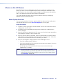
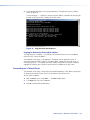
Powering On
Apply power to the DVS by connecting the provided IEC power cord from the rear panel
power connector to an AC power source. The scaler performs a self-test during which all
the front panel buttons blink red, then green, then amber. At the same time, the initial two
power-up screens are displayed on the LCD screen. At the completion of the self-test, all
button lights turn off except for the previously selected Input button (Input 1 by default) and
the Menu and Next buttons, all of which continue to be lit amber. If picture-in-picture (PIP)
mode was enabled previously, the input button for the PIP source and the PIP On/Off button
light green. The LCD panel displays the default cycle.
If an error occurs during the self-test, the DVS locks up and does not operate. If this
occurs, call the Extron S3 Sales & Technical Support Hotline. (See the rear cover for contact
information in your area.)
When power is first applied to the DVS, the LCD panel displays Initializing Please
Wait..., then Extron, DVS 510 Vn.nn, where n.nn is the current firmware version. If
the DVS self-test completes successfully, the default cycle begins, in which the LCD panel
display alternates between the current output resolution and refresh rates, and the currently
selected input number, signal type, and horizontal and vertical frequencies. These two
screens continue to cycle on the screen when the menu system is not in use.
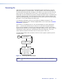
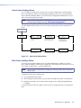
The flow diagram below shows the order in which the screens appear at power-up and in
the default cycle.
Power
On
Initializing
Please Wait...
2 sec.
Extron
DVS 510
V1.00
In # 5
47.8KhZ
5 sec.
RGB
60.0Hz
Default Cycle
5 sec.
Output Rate
1080i @ 60Hz
Figure 12. Power-up and Default Cycle
NOTE: Audio and video mute settings are not retained when power is cycled to the
DVS.
DVS 510 Series • Operation
17
Picture-in-Picture (PIP) Mode
The picture-in-picture (PIP) feature lets the DVS display two image sources on the screen
simultaneously.
One of these image sources must be low-resolution (composite, S-video, YUVi, or RGBcvS)
video, while the other must be high resolution (YUVp/HDTV, RGB, or DVI) video.
•
High resolution — Inputs 5 through 7 and 9 if they are configured as RGB (RGBHV,
RGBS or RGsB) or high-resolution component video YUVp/HDTV; inputs 8 and 10 (DVI).
•
Low resolution — Inputs 1 through 4; and 5, 6, 7, and 9 when they are configured as
component video YUVi or RGBcvS
The PIP function toggles between the selected input in each resolution group. The PIP
function cannot toggle between two inputs in the same resolution group.
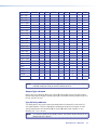
The following table shows the resolution of each input:
Input
High Resolution
Low Resolution
1
Composite
2
Composite
3
S-video
4
S-video
5
RGB, YUVp/HDTV
YUVi, RGBcvS
6
RGB, YUVp/HDTV
YUVi, RGBcvS
7
RGB, YUVp/HDTV
YUVi, RGBcvS
8
DVI (all formats)
9
RGB, YUVp/HDTV
10
DVI (all formats)
YUVi, RGBcvS
By default, the PIP image is one-fourth the size of the main window and is positioned in the
lower-right corner of the display.
NOTE: The size of the PIP window can be set in the menu system (see “Enabling
PIP Mode,” on the next page). The position of the PIP window is set with the
centering adjustment (see “Picture Controls” on page 36 for details).
When PIP mode is active:
•
The button for the main window input lights amber. The PIP input button lights green.
•
All picture controls configure only the image in the PIP window. The main window
settings cannot be modified while the PIP window is active. The PIP size and position
can be adjusted with the same front panel controls or SIS commands used to adjust the
main image.
•
The parameters of the PIP window are adjustable from the front panel menus or by SIS
commands only.
•
Any change in configuration (except sizing or positioning) of the PIP window is saved to
that input even after the PIP mode is no longer active.
•
The PIP window input is shown in the default cycle as the current input.
•
If the PIP window source is not active, the PIP mode exits until an active signal is
detected. When the main window source is removed, a black background is displayed.
•
Audio and video breakaway are not allowed.
DVS 510 Series • Operation
18
Enabling PIP Mode
To enable picture-in-picture mode:
1. Select an input for the main window. The selected input button lights amber.
2. Configure the input for the main window as desired (see “Input Configuration
Menu” on page 23 and “Picture Controls” on page 36).
3. Press the PIP On/Off button to activate the PIP mode.
•
The input button for the PIP window lights green.
NOTE: The first time the DVS is placed in PIP mode, by default input 1 is
selected if the main input is high resolution, and input 5 is selected if the
main input is low resolution. If PIP mode has been enabled previously,
the input in the correct resolution category that was the PIP input most
recently is selected.
•
The PIP window appears on the screen in its previously displayed size and position.
(On first activation, the PIP window appears in the default size and position.)
4. Configure the PIP window as desired, using the same methods you used to configure
the main window in step 2.
You can also enable PIP via SIS commands (see the Picture-in-picture [PIP] commands
on page 60 in the Command and Response Table for SIS Commands), the Windowsbased control software (see the SPPCP help file), the web pages (see “PIP Setup Page”
on page 104), or using the IR remote control (see “Using the Optional IR 904 Remote
Control” on page 43).
Changing the PIP Input
To change the input for the PIP window or the main window, determine if the corresponding
input is low- or high-resolution.
If your main window image is from a low-resolution source, switch to another low-resolution
input from the front panel.
NOTE: The front panel buttons do not permit you to select two low-resolution or two
high-resolution inputs. For example, if you have selected input 1 (composite) for
the main window (the button is lit amber) and then you press the button for
input 2 (also composite), input 2 is selected for the main window (lights amber)
and input 1 is deselected.
Using the PIP Swap Feature
Use the swap feature to switch the active main window input with the current PIP input.
For example, if the main window is input 5 (RGB scaled) and the PIP window is input 1
(composite), applying the swap command results in input 1 becoming the main window and
input 5 the PIP window.
To swap the main window input with the PIP input, press the PIP Swap button. The buttons
switch colors from amber to green and vice versa.
You can set audio to follow the main (default) window or the PIP window. Audio breakaway
is not possible while PIP mode is on; audio must follow either the main window or the PIP
window.
DVS 510 Series • Operation
19
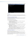
Menus on the LCD Screen
The DVS 510 menus that are displayed on the LCD screen enable you to configure and
operate the scaler. The menu navigation buttons (Menu and Next) are located to the right
of the LCD screen. Press these buttons to cycle through the available menus and submenus,
and use the horizontal and vertical Adjust knobs to select options.
This section describes the options on these menus and their submenus, including any
procedures that are initiated from them.
Menu System Overview
The menu system consists of six menus, some of which have submenus that enable you to
make desired adjustments (see the menu flow diagram on the next page).
Using the menus
1. To access the menu system, press the Menu button. The first menu name (User Presets)
is displayed on the LCD screen.
2. Select other menus by repeatedly pressing the Menu button until the desired menu
name is displayed.
3. When the desired menu appears on the LCD screen, press the Next button repeatedly to
cycle through the submenus for the selected menu.
4. When the desired submenu is displayed, rotate the horizontal ([) or vertical ({) Adjust
knob clockwise or counterclockwise to cycle through the submenu options. If you want
to return to a menu from within one of its submenus, press Menu.
5. When the desired option is displayed, do one of the following to select it:
•
Press Next to display another submenu.
•
Press Menu repeatedly until the Exit Menu? Press NEXT screen appears, then press
Next to return to the default cycle.
•
Do nothing more, and wait until the LCD screen returns to the default cycle
(approximately 30 seconds).
NOTE: The menus time out and the default cycle is displayed after 30 seconds of
inactivity; however, any selections you made with the Adjust knobs are saved
and remain in effect until you change them or reset the unit to factory defaults
(see “Resetting” on page 40).
DVS 510 Series • Operation
20
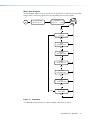
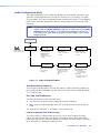
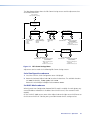
Menu flow diagram
The flow diagram below shows the menus that are displayed in the front panel LCD window
and the order in which they appear when you repeatedly press the Menu button.
Power
On
Initializing
Please Wait...
2 sec.
Extron
DVS 510
V1.00
2 sec.
Default
Cycle
Menu
User
Presets
30 sec.
Menu
Input
Configuration
30 sec.
Menu
Output
Configuration
30 sec.
Menu
Audio
Configuration
30 sec.
Menu
Advanced
Configuration
30 sec.
Menu
View
Comm Setting
30 sec.
Menu
Menu
Exit Menu?
Press NEXT
30 sec.
Next
Figure 13. Main Menu
The following sections describe the submenu options for each of the menus.
DVS 510 Series • Operation
21
User Presets Menu
User presets save the current set of image parameters for the selected input. Each input has
16 available user memory presets to which you can save settings or recall using this menu,
an SIS command (see the User presets commands in the Command and Response Table for
SIS Commands on page 62) or the Presets web page (see “Memory/Input Presets Page”
on page 102).
The following settings are saved in a user preset:
• Color
• Horizontal position
• Tint
• Vertical position
• Contrast
• Horizontal size
• Brightness
• Vertical size
• Detail
• Pan
• Zoom
Saved user presets can be recalled to be applied to the current input.
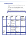
The following flowchart provides an overview of the User Preset submenus and the options
for each setting.
Default
Cycle
Menu
User
Presets
Next
Use either Adjust knob to
select a submenu option.
Recall Preset
<16>
•
•
NA
1 through 16
Next
Save Preset
<NA>
• NA
• 1 through 16
Next
Figure 14. User Presets Menu
Saving or recalling a user preset
1. Press the Menu button until User Presets is displayed in the LCD window.
2. Press the Next button until the desired submenu name is displayed: Recall Preset or
Save Preset.
3. Rotate either Adjust knob until the LCD screen displays the number of the preset to
which you want to save the current settings, or that you want to recall.
4. Press Next to save or recall the preset. The User Presets menu is displayed.
To exit the user presets function without saving a preset, press Menu.
NOTES: • The presets are saved in nonvolatile memory; therefore, powering down the
DVS does not lose the presets.
• User presets can be saved at one input resolution and rate and recalled to a
different one.
Example: If the current output resolution is 1024x768 and a 720p input is
applied, you can size and center a “letterbox” image for a 16:9 input resolution
and save it to a user preset. Subsequently, if a 1080p resolution is applied to the
unit, the letterbox preset that was saved at 720p can be recalled with the new
1080p input resolution.
DVS 510 Series • Operation
22
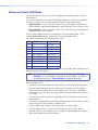
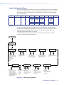
Input Configuration Menu
The Input Configuration menu allows you to select a video signal type for the configurable
inputs: 5, 6, 7, and 9. (Inputs 1 and 2 are composite video only, inputs 3 and 4 are S-video
only, and inputs 8 and 10 are DVI only.) The table below summarizes the available signal
types for each input.
Input 1
Input 2
Input 3 Input 4
Composite Composite S-video
Input 5
Input 6
Input 7
Input 8
Input 9
Input 10
RGB*
RGB*
RGB*
DVI
RGB*
DVI
YUVp/
HDTV
YUVp/
HDTV
YUVp/
HDTV
YUVp/
HDTV
RGBcvS
RGBcvS
RGBcvS
RGBcvS
YUVi
YUVi
YUVi
YUVi
S-video
*Default
You can also enable and disable film detection; select the horizontal and vertical start
positions, pixel sampling phase, total pixels, active pixels, active lines; and select an EDID
(extended display identification data) for an input. Rotate the horizontal ([) or the
vertical ({) Adjust knob to adjust the settings.
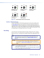
The following flowchart provides an overview of the Input Configuration menu and
submenus and the options for each setting.
User
Presets
Menu
Input
Configuration
Next
Input # 5
RGB
Input # 5
Film Detect: Off
Next
Film Detect
Turn Film Detection on
or off.
Input video type
For inputs 5, 6, 7, and 9,
select an available signal
format:
• RGB (Default)
• YUVp/HDTV
• RGBcvS
• YUVi
Next
Input # 5
Vert Start: 128
Vertical Start
Select a vertical start
line position for the top
edge of the active video.
Next
Input # 5
Horz Start: 128
Horizontal Start
Select a horizontal start
pixel position for the left
edge of the active video.
Next
Input # 5
Pixel Phase: 16
Pixel Phase
Adjust the pixel sampling
point.
Next
Next
Input # 5 EDID
1280x1024 60 Hz
Resolution
Select the input resolution:
• Match Output (Default)
• See the Resolution and
Refresh Rate table in the
“Output Configuration Menu”
section for a complete list of
available resolutions.
Next
Refresh Rate
Select the rate:
• 50 Hz
• 59.9 Hz
• 60 Hz
• 75 Hz
Input # 5
Active Lns: 1080
Active Lines
Specify the height in lines
of the active image area to
be sampled.
Next
Input # 5
Active Pix: 1920
Active Pixels
Specify the width in pixels
of the active image area to
be sampled.
Next
Input # 5
Total Pix: 2750
Total Pixels
Specify the width in pixels
of the total image area to
be sampled.
Figure 15. Input Configuration Menu
DVS 510 Series • Operation
23
Selecting an input
To select an input, press the numbered input button. The button lights amber. The selected
input number is displayed in the LCD window on the first screen of the default cycle. Inputs
can also be selected via an SIS command, the SPPCP software, the web pages, and the
IR 904 remote control.
In #5
RGB
47.8kHz
60.0Hz
Configuring an input
Follow these steps to configure any of the 10 video inputs:
1. Press the numbered button for the input to configure.
2. Press the Menu button until Input Configuration is displayed in the LCD window (see
figure 15 on the previous page.
3. Press the Next button repeatedly until the desired input parameter submenu is displayed.
4. Rotate either Adjust knob until the desired submenu option is displayed.
NOTE: For EDID settings, rotate the horizontal knob ([) to adjust the resolution
and the vertical Adjust knob ({) to select a refresh rate (inputs 5, 6, 8, and
10 only).
5. To save the input configuration, press Menu once or Next repeatedly to return to the top
level menu.
Alternatively, wait for the LCD display to time out and return to the default cycle
(approximately 30 seconds). The DVS saves the new settings.
NOTE: Depending on the signal type of the selected input, different adjustments are
available for the different inputs (see the table below).
Available input adjustments
The following table shows which adjustments are available for each input type.
Composite
(Inputs 1
and 2)
S-video
(Inputs 3
and 4)
RGB
(Inputs 5, 6, 7,
and 9)
X
X
X
X
Vert. Start
X
X
Horiz. Start
X
X
Pixel Phase
X
X
Total Pixels
X
X
Film Detect
YUVp/HDTV
RGBcvS
YUVi
(Inputs 5, 6, (Inputs 5, 6, (Inputs 5, 6,
7, and 9)
7, and 9)
7, and 9)
DVI
(Inputs 8
and 10)
X
X
X
Active Pixels
X
X
X
X
X
X
X
Active Lines
X
X
X
X
X
X
X
EDID
X
(Inputs 5 and 6
only)
X
Input configuration submenu adjustments
The table on the next page shows how to make the selections and adjustments that are
accessed through the Input Configuration submenus.
DVS 510 Series • Operation
24
Input Configuration Submenu
Horizontal ([) and Vertical Knob ({) Adjustment
Video Signal Type (Inputs 5, 6, 7, and 9)
Select the desired video format for the selected input
(this adjustment is available only for inputs 5, 6, 7, and
9). The default is RGB.
Accepted video signal types include RGB, RGBcvS,
YUVp/HDTV, and YUVi.
Film Mode Detect
Enable and disable 3:2 pulldown detection for NTSC and
2:2 film detection for PAL video sources.
Select On or Off to turn 3:2 or 2:2 pulldown (film mode)
detection on and off for the selected input. The default
is Off.
3:2 and 2:2 pulldown (film modes) help maximize image
detail and sharpness for video sources that originated
from film. When film is converted to NTSC video, the
film frame rate must be matched to the video frame
rate. “Jaggies” and other image artifacts can result if
conventional de-interlacing techniques are used on filmsource video.
When film mode is enabled, the DVS recognizes
signals that originated from film and then applies video
processing algorithms that optimize the conversion
of video that was made with the 3:2 or 2:2 pulldown
process. This results in sharply detailed images.
Vertical Start Position
Select the vertical start position. The default is 128.
The distance in pixels from the top edge of the total
video display area for the selected input to the top edge
of its active area
Horizontal Start Position
Select the horizontal start position. The default is 128.
The distance in pixels from the left edge of the total
video display area for the selected input to the left edge
of its active area
Pixel Phase (Inputs 5, 6, 7, and 9)
The point at which pixels are sampled (available only for
RGB and YUVp/HDTV inputs)
Total Pixels (Inputs 5, 6, 7, and 9)
The width in pixels of the total video display area
(available only for RGB and YUVp/HDTV inputs)
Active Pixels
The width in pixels of the active video area
Active Lines
The height in lines of the active video area
EDID (Extended Display Identification Data)
(Inputs 5, 6, 8, and 10)
The resolution and refresh rate of a display device
(available only for RGB and DVI inputs)
Select the amount to move the pixel sampling point
to ensure output clarity. The range of settings is 0-31;
default is 16.
Select the width in pixels of the total video display area
for the selected input. The default width is marked with
an asterisk (*) on the LCD screen.
Select the width in pixels of the active video area for
the selected input. The default width is marked with an
asterisk (*) on the LCD screen.
Select the height in lines of the active video area of the
selected input. The default width is marked with an
asterisk (*) on the LCD screen.
Select an EDID to apply to the selected input.
• The Horizontal ([) Adjust knob selects the
resolution.
• The Vertical ({) Adjust knob selects the refresh rate.
NOTE: This submenu is not displayed when
input 1-4, 7, or 9 is selected.
DVS 510 Series • Operation
25
Output Configuration Menu
The output configuration menu allows you to set output resolution and refresh rate, output
signal type, and sync polarity (RGBHV only). The following flow diagram shows the output
configuration submenus and the adjustments that can be made from them.
Input
Configuration
Menu
Output
Configuration
Next
Next
Resol 1024 x 768
Refresh
@ 60 Hz
Resolution
Refresh Rate
Select the output resolution
and refresh rate.
See the table on the next page
for available combinations of
resolutions and refresh rates.
Default: 1024 x 768 @ 60 Hz
Output Type
RGBHV
Next
Next
Video signal types
Select the output signal format:
• RGBHV (default)
• RGBS
• RGsB
• YUV Bi-level (EDTV standard)
• YUV Tri-level (HDTV standard)
Sync Polarity
H –
V –
Polarity combinations
Select the sync polarity
combination:
• H – V – (default)
• H– V+
• H+ V–
• H+ V+
• N/A*
Next
*Appears when a signal type
other than RGBHV is selected.
Figure 16. Output Configuration Menu
Resolutions and refresh rates submenu
While the Output Configuration menu is displayed, rotate the horizontal Adjust ([) knob
to select the output resolution and the vertical Adjust ({) knob to select the refresh rate. The
default resolution and rate for the DVS 510 Series are 1024x768 @ 60 Hz.
The table on the next page shows the available resolutions and refresh rates on the
DVS 510 Series.
DVS 510 Series • Operation
26
Resolution
23.98 Hz 24 Hz
25 Hz
29.97 Hz 30 Hz 50 Hz 59.94 Hz 60 Hz 75 Hz
640 x 480
X
X
X
800 x 600
X
X
X
852 x 480
X
X
X
1024 x 768*
X
X*
X
1024 x 852
X
X
X
1024 x 1024
X
X
X
1280 x 768
X
X
X
1280 x 800
X
X
X
1280 x 1024
X
X
X
1360 x 765
X
X
X
1360 x 768
X
X
X
1365 x 768
X
X
X
1366 x 768
X
X
X
1365 x 1024
X
X
X
1440 x 900
X
X
X
1400 x 1050
X
X
1680 x 1050
X
X
1600 x 1200
X
X
1920 x 1200
X
X
480p
X
X
576p
X
X
X
X
X
X
X
X
X
720p
X
X
X
1080i
1080p
X
X
X
X
X
X
X
X
2048 x 1080
X
X
X
X
X
X
X
X
*Default resolution
NOTE: The default refresh rate of 60 Hz is applied when the DVS switches to a different
resolution except for 576p, for which it defaults to 50 Hz.
Output Type submenu
Rotate either the horizontal ([) or the vertical ({) Adjust knob to select the output video
format required by the display. Available signal types are RGBHV (default), RGBS, RGsB, YUV
bi-level, and YUV tri-level.
Sync Polarity submenu
The display device may require a particular combination of horizontal (H) and vertical (V)
sync signal polarities. Select the appropriate combination of positive or negative H and V
sync by rotating either the horizontal ([) or vertical ({) Adjust knob. Options are H-V(default), H+V-, H-V+, or H+V+.
NOTE: This submenu applies only to RGBHV format. For all other output formats, N/A is
displayed for this submenu.
DVS 510 Series • Operation
27
Audio Configuration Menu
The Audio Configuration menu enables you to adjust the levels of gain, attenuation, bass,
and treble; enable and disable the limiter for the amplifier (DVS 510 SA only); turn audio
delay on and off; and select the audio output type (stereo or dual mono). The flow diagram
below shows the Audio Configuration submenus and the adjustments that can be made
from them.
NOTE: The volume of the Variable output can be adjusted via the DVS front panel
Volume knob (see Volume Control on page 39), SIS commands (see the Audio
Volume commands on page 61 in the Command and Response Table for SIS
Commands) or the Signal Processing Products Control Program (see the control
program help file).
Output
Configuration
Menu
Audio
Configuration
Use either Adjust knob to
select a submenu option.
Next
Next
Gain/Attenuation
0 dB
Audio Output
Select the audio output type.
• Stereo (Default)
• Dual Mono
Treble
0 dB
Next
Treble
Set the treble level.
• Range: -12 through +12
• Default: 0
Bass
Set the bass level.
• Range: -12 through +12
• Default: 0
Gain /Attenuation
Set the audio gain or
attenuation for the
selected input.
• Range: -12 through +12
• Default: 0
Audio Output
Stereo
Bass
0 dB
Next
Next
Audio Delay
On
Next
Limiter
On
Next
Audio Delay
Set audio delay to On or Off.
• On: Delays the audio to
match the video delay
(default).
• Off
Limiter*
Set the limiter to On or Off.
• On: Automatically
reduces audio level
to prevent clipping.
• Off (default)
*This submenu appears only
on the DVS 510 SA.
Figure 17. Audio Configuration Menu
Gain/Attenuation submenu
To set the gain and attenuation levels from this submenu, rotate either Adjust knob to the
right to select the gain (0 through +12) and to the left to select the attenuation (0 through
-12). The default is 0.
Bass and Treble submenus
To increase or decrease the bass and treble levels:
1. Press Next until the desired submenu (Bass or Treble) is displayed.
2. Rotate either the Adjust knob right to increase or left to decrease the level of bass or
treble.
The range for bass and treble is -12 through +12; the default is 0.
Limiter submenu (DVS 510 SA only)
The Limiter submenu is displayed only on the DVS 510 SA. When enabled, the limiter
reduces the amplifier level to prevent clipping. To enable the limiter, rotate either Adjust
knob to the right until the LCD screen displays On. To disable the limiter, rotate either knob
to the left until Off is displayed. The default is Off.
DVS 510 Series • Operation
28
Audio Delay submenu
This submenu lets you delay the audio to match the video delay. To enable audio delay,
rotate either Adjust knob to the right until the LCD screen displays On. To disable audio
delay, rotate either knob to the left until Off is displayed. The default is On.
Audio Output submenu
From this submenu you can select stereo or dual mono for the audio output type.
•
In stereo mode, the audio signal from the left channel is output to one speaker while
the signal from the right channel is output to the other speaker.
•
In dual mono mode, the inputs from the left and right channels are summed together
and are output to the speakers together as two mono channels, so that the left and
right outputs contain the same combined signal information.
To select the audio type, rotate either adjust knob right to select Stereo or left to select
Dual Mono. The default is Stereo.
Advanced Configuration Menu
Use the Advanced Configuration menu to enable auto-imaging for one or more selected
inputs, enable or disable auto memories, select the aspect ratio to be displayed for the
current input, set the amount of seconds for RGB delay, select a switch effect, select a test
pattern, view the DVS internal temperature, and initiate a reset of the scaler to factory
defaults.
Figure 18 shows a flow diagram of the Advanced Configuration menu and submenus and
the adjustments that are available from them. Config Menu
Audio
Configuration
Menu
Advanced
Configuration
Next
Auto Image
Input # 1 Off
Next
Input Number
Select an input:
1 through 10.
Next
Auto Image
Enable or disable
Auto-image:
• On
• Off (default)
Reset to Factory
Press Detail
Reset to Factory
Defaults
Press the Detail button to
reset the unit to its
factory default settings.
When finished, system
returns to default cycle.
Next
Auto Memories
On
Auto Memories
Enable or disable auto
memories:
• On (default)
• Off
Internal Temp.
100.40F
38C
Unit Internal
Temperature
Current internal
temperature expressed in
degrees Fahrenheit and
Celsius (not adjustable)
Aspect Ratio
Fill
Next
Next
Aspect Ratio
Select display aspect
ratio:
• Fill (default)
• Follow
Next
Test Pattern
Off
RGB Delay
0.5 Seconds
RGB Delay
Select RGB delay in
0.1-second increments.
• Range: 0.0 through 5.0
• Default: 0.5
Next
Test Pattern
Select a test pattern:
• Off (default)
• White Field
• Color Bars
• Crop
• Crosshatch
• 1.33 Aspect
• 4x4 Crosshatch
• 1.78 Aspect
• Grayscale
• 1.85 Aspect
• Ramp
• 2.35 Aspect
• Alternating Pixels • Blue Mode
Next
Switch Effect
Fade
Switch Effect
Select the effect displayed
when input is switched:
• Cut
• Fade (default)
Figure 18. Advanced Configuration Menu
DVS 510 Series • Operation
29
Auto Image submenu
Auto-Image is enabled per input. When an input is connected and Auto-Image is enabled,
the DVS performs an image adjustment in which it measures where the active area starts
and stops, then adjusts input sampling accordingly, so that the image fills the window.
The scaler measures the sync frequencies of the incoming video source and sets the active
image area, total image area, and the sampling frequency according to a table stored on the
DVS. If an unknown input is connected to the DVS, the scaler measures and estimates the
resolution of the incoming video. If the estimate proves inaccurate, the Auto-Image function
makes measurements to more accurately set up the input sampling.
Auto-image affects the following settings:
•
Active pixels
•
Horizontal position
•
Active lines
•
Vertical position
•
Horizontal start
•
Horizontal size
•
Vertical start
•
Vertical size
•
Pixel phase
All other settings are unchanged when an Auto-Image is performed.
If the aspect ratio is set to Fill, the horizontal and vertical position is set to 0,0, and the
horizontal and vertical size is set to match the current output rate. If the aspect ratio is set to
Follow, the horizontal and vertical position is set to maintain the native aspect ratio of the
input with respect to the current output resolution.
If auto memories are enabled, the DVS first checks for an existing memory entry for the
connected input (see “Auto Memories submenu”).
Auto-Image is useful in applications in which a variety of input sources are likely to be
encountered, such as on a lectern or podium where guest laptops might be plugged in.
To enable or disable Auto-Image for an input:
1. From the Advanced Configuration menu, press Next until the Auto Image submenu is
displayed.
2. Rotate the horizontal Adjust knob ([) to select the input to be auto-imaged.
3. Rotate the vertical Adjust knob ({) to select On or Off for Auto-Image.
The default input selection is input 1; the default Auto-Image status is Off.
Auto Memories submenu
When auto memories is activated, the DVS stores size, position, and picture settings based
on the incoming signal from the connected input. When the same input signal is detected
again, these image settings are recalled from memory.
To enable or disable auto memories:
1. Press Next until the Auto Memories submenu is displayed.
2. Rotate either Adjust knob to the right to select On or to the left to select Off.
The default for auto memories is On. It is recommended that auto memories not be disabled
unless you are using an input preset (selectable via SIS commands, the SPPCP, and the web
pages) or if you want each input to be treated as a new input without using saved settings.
NOTE: When an Auto-Image is performed, auto memory is checked first and if an entry
is found, its settings are used. If you do not want to use the auto memories
settings, disable auto memories before allowing Auto-Image to be performed.
(See the table below for the results of the possible combinations of Auto-Image
and auto memories settings.)
DVS 510 Series • Operation
30
Auto Memories and Auto-Image Interaction
Auto memories
Auto-Image
Action
On
On
New signals or rates that have not been previously
detected by the DVS 510 are initially set up using default
parameters, then Auto-Image is applied and the values are
stored. The next time that signal is detected, the values
stored in the auto memory location are applied.
On
Off
(Default) New signals or rates that have not been
previously detected by the DVS 510 are set up using
default parameters. If manual input or picture settings are
made to the input, an auto memory location is created and
recalled each successive time the input is detected.
Off
On
Each change in input sync triggers an automatic
Auto-Image. When auto memory is disabled, each change
in sync is treated as a new signal and an automatic
Auto-Image is triggered. Any manual changes made to the
image and picture controls are lost each time a new rate is
detected.
Off
Off
Each change in input sync causes default values to be
applied to the rate. Any manual changes made to the
image and picture controls are lost when a new rate is
applied.
Aspect Ratio submenu
The aspect ratio control allows you to select between Fill (the input signal at each rate fills
the entire output raster), or Follow (the input signal at each rate is displayed with its native
aspect ratio [default setting]).
•
In fill mode, if you want an aspect ratio adjustment for a single input rate, you can set
up the correct size and centering by using one of the Aspect Ratio test patterns as a
template (see “Test Pattern submenu” on the next page). If auto memories is enabled,
this setting is saved and recalled the next time the signal is detected.
•
In follow mode, each input rate is displayed with its native aspect ratio (4:3, 5:4, 16:9,
or 16:10). You can view the correct letterbox or pillar box settings by pressing the Size
or the Position button. If a single input is to fill the entire raster in follow mode, you can
manually set the position (center) to 0,0 and the size to match the current output rate
(see “Picture Controls” on page 36).
To select the aspect ratio mode:
1. From the Advanced Configuration menu, press Next until the Aspect Ratio submenu is
displayed.
2. Rotate either Adjust knob to select the desired mode.
RGB Delay submenu
The RGB delay feature applies a brief delay before displaying a new input on a screen,
allowing the display device to adjust to the new sync timing. This delay shows the viewers a
blank screen, masking any glitch during switching. The RGB Delay options are 0 to 5 seconds
in 0.1-second increments.
To set the RGB Delay time:
1. From the Advanced Configuration menu, press Next until the RGB Delay submenu is
displayed.,
2. Rotate either Adjust knob to select the amount of delay.
DVS 510 Series • Operation
31
Switch Effect submenu
Two effects are available to be displayed on the output screen when the input is switched:
•
Cut — The current input is immediately replaced with the image from the new input.
•
Fade — The current input fades to black and the new input fades in (default).
To select a switch effect:
1. From the Advanced Configuration menu, press Next until the Switch Effect submenu is
displayed.
2. Rotate either Adjust knob to the right to select Fade or to the left to select Cut.
Test Pattern submenu
The following test pattern selections are available via this submenu to help you adjust the
display device for color, convergence, focus, resolution, contrast, grayscale, and aspect ratio:
•
Off (default)
•
•
Color Bars•
Crop
•
Crosshatch•
1.33 Aspect
•
4x4 Crosshatch
•
1.78 Aspect
•
Grayscale•
1.85 Aspect
•
Ramp•
2.35 Aspect
•
Alternating Pixels •
Blue Mode
White Field
NOTE: • Alt Pixels is used to calibrate display devices input sampling to the DVS
output. Use this pattern to adjust the clocking and phasing at the
display until no more vertical bands are visible.
• Crop is used to center the DVS output on the display device. Adjust the
horizontal and vertical position on the display until all four crop lines are
visible.
• Color Bars is used to calibrate color settings on the display and to confirm
proper system wiring.
• Blue Mode causes only sync and blue video signals to pass to the display. This
can assist you in setting up the color and tint levels of the video input.
DVS 510 Series • Operation
32
Color Bars
Crop
Crosshatch
1.33 Aspect
4x4 Crosshatch
1.78 Aspect
Grayscale
1.85 Aspect
Ramp
2.35 Aspect
Alt Pixels
Blue Mode
White Field
Figure 19. DVS 510 Series Test Patterns
To select a test pattern:
1. From the Advanced Configuration menu, press Next until the Test Pattern submenu is
displayed.
2. Rotate either Adjust knob to select a test pattern. The default is Off (no test pattern).
Internal Temp. screen
The Internal Temp. screen shows the current internal temperature of the DVS unit in degrees
Fahrenheit and Celsius. This is an information-only screen; no adjustments can be made
from it.
Reset to Factory screen
This screen lets you reset the DVS to the default settings with which it was delivered from
the factory. To reset the unit:
1. From the Advanced Configuration menu, press Next until the Reset to Factory Press
Detail screen is displayed. The Detail button under Picture Controls begins to blink.
2. To initiate the reset, press Detail. When the reset is complete, the default cycle is
displayed.
DVS 510 Series • Operation
33
View Comm Settings Menu
The View Comm Settings menu lets you view the current settings for the communication
ports, including the IP, subnet mask, and gateway addresses of the unit, the MAC (Media
Access Code or hardware) address, the Dynamic Host Configuration Protocol (DHCP) status,
and the serial port baud rate and type.
NOTE: None of the settings can be changed from this menu; to make adjustments, use
the Edit Comm Settings menu (see “Edit Comm Settings Menu”).
The flow diagram below shows the screens and the settings that can be viewed from this
menu.
Advanced
Configuration
Menu
View Comm
Settings
Next
Serial Port
9600
RS232
MAC Address
0005A605CDC7
Next
Next
MAC Address
View Media Access Code
(MAC) hardware address.
Serial Port
View baud rate and port
protocol.
DHCP Mode
Off
DHCP Mode
View Dynamic Host
Configuration Protocol
(DHCP) On/Off status.
Next
Next
IP Address
192.168.254.254
IP Address
View unit IP address.
Subnet Mask
255.255.000.000
Next
Subnet Mask
View subnet mask IP address.
Next
Gateway Address
000.000.000.000
Gateway Address
View gateway IP address.
Figure 20. View Comm Settings Menu
Edit Comm Settings Menu
This menu lets you make changes to the serial port configuration, IP addresses, and the
DHCP mode. Although the Edit Comm Settings menu has almost all the same screens as the
View Comm Settings menu, it is accessed differently.
NOTE: You can access the Edit Comm Settings menu from any other menu or from the
default cycle.
To display the Edit Comm Settings menu:
1. Press and hold the Next button.
2. While holding the Next button, press the Detail and Color/Tint buttons simultaneously.
3. Hold all three buttons until the Edit Comm Settings screen is displayed (approximately
2 seconds).
If no activity occurs within 30 seconds, the DVS saves all settings and returns to the default
cycle.
DVS 510 Series • Operation
34
The flow diagram below shows the Edit Comm Settings screens and the adjustments that
are available from them.
Press and hold
Next + [Detail+Color/Tint].
2 Sec.
Edit Comm
Settings
Next
Serial Config
9600
RS232
Next
Select the baud rate:
9600 (Default)
19200
38400
115200
•
•
•
•
Set DHCP Mode
Off
Next
Select the serial
communication type:
• RS232
• RS422
Set the DHCP mode:
Off (Default)
On
•
•
Set Gateway Addr
000.000.000.000
Set the Gateway Address:
Select an octet.
Increase or decrease the
selected number:
• Range: 000 through 255
(each octet)
• Default: 000.000.000.000
Next
Next
Set IP Address
192.168.254.254
Set the IP Address:
Increase or decrease
Select an octet.
selected number:
• Range: 000 through 255
(each octet)
• Default: 192.168.254.254
Next
Set Subnet Mask
255.255.000.000
Set the Subnet Mask:
Select an octet.
Increase or decrease the
selected number:
• Range: 000 through 255
(each octet)
• Default: 255.255.000.000
Figure 21. Edit Comm Settings Menu
Adjustments can be made via the following Edit Comm Settings screens:
Serial Configuration submenu
1. Press Next until the Serial Configuration screen is displayed.
2. Rotate the horizontal Adjust knob ([) to select the baud rate. The available selections
are 9600 (the default), 19200, 38400, and 115200.
Rotate the vertical Adjust knob ({) to select RS232 or RS422.
Set DHCP Mode submenu
When Dynamic Host Configuration Protocol (DHCP) mode is enabled, the scaler ignores any
entered IP address and obtains its IP address from a DHCP server (if the network is DHCP
capable).
On the Set DHCP Mode screen, rotate either Adjust knob to the right to turn DHCP on or to
the left to turn DHCP off. Contact your system administrator for the setting to select.
DVS 510 Series • Operation
35
Set IP Address submenu
Valid IP addresses consist of four 1-, 2-, or 3-digit numeric sub-fields (called “octets”) that
are separated by periods. Each octet can be numbered from 000 through 255 (leading zeros
are inserted by the DVS). The factory-installed default address is 192.168.254.254, but if
this conflicts with other equipment at your installation, you can change the IP address to any
valid value via the Set IP Address screen.
To change the unit IP address:
1. Press Next until the Set IP Address screen is displayed.
2. Rotate the horizontal Adjust knob ({) to select an octet. (The selected octet flashes.)
3. Rotate the vertical Adjust knob ([) to increase or decrease the flashing number.
Set Subnet Mask submenu
The subnet mask is used to determine whether the DVS is on the same subnet as the mail
server when you are using a subnet (see “Subnetting, a Primer” on page 120). The subnet
mask address has the same validity rules as the IP address. The default subnet mask is
255.255.000.000.
To change the subnet mask:
1. Press Next until the Set Subnet Mask screen is displayed.
2. Rotate the horizontal Adjust knob ({) to change the flashing octet selection.
3. Rotate the vertical Adjust knob ([) to increase or decrease the flashing number.
Set Gateway Addr submenu
The gateway address identifies the gateway to the mail server that will be used if the
scaler and the mail server are not on the same subnet. The default gateway address is
000.000.000.000.
To change the gateway address:
1. Press Next until the Set Gateway Addr screen is displayed.
2. Rotate the horizontal Adjust knob ({) to change the flashing octet selection.
3. Rotate the vertical Adjust knob ([) to increase or decrease the flashing number.
NOTE: The Edit Comm Settings menu has no MAC address screen, because the MAC
address cannot be changed.
Exiting the Menu System
To exit the menu system, press the Menu button repeatedly until the Exit Menu? Press
NEXT screen appears. Press the Next button to return to the default cycle.
Alternatively, wait until the menu system times out and the default cycle resumes
(approximately 30 seconds).
Picture Controls
The DVS has six picture control buttons located on the front panel to the right of the PIP
buttons. You can use these buttons to adjust size, position, brightness and contrast, color
and tint, detail, magnification (zoom), and select a portion of the image on which to
focus the view (pan). (See the Picture Controls Summary table on the next page for an
explanation of these button functions.)
NOTE: When PIP mode is active, all these picture controls apply to the PIP window. To
configure the main window, press the PIP On/Off button to exit PIP mode.
DVS 510 Series • Operation
36
Adjusting the Picture Controls
To adjust the picture controls for the currently selected input:
1. Press the button for the input that you want to adjust. If you want to adjust the PIP
window, press the PIP On/Off button to enter PIP mode, then press the button for the
PIP input.
2. Press the desired picture control button: Size, Bright/Cont (brightness and contrast),
Detail (sharpness), Position (centering), Color/Tint (color quality), or Zoom/Pan
(magnification or horizontal and vertical panning).
3. Rotate the horizontal ([) and vertical ({) Adjust knobs to select a level from the
available range.
4. Repeat steps 1 through 3 for each image adjustment you want to make for the selected
input.
NOTE: The LCD screen displays N/A in place of a value if that adjustment does not
apply to the video format of the input.
Picture Controls Summary
The following table explains the functions of the Picture Controls buttons and how to make
adjustments. (In the Display column, n is a single digit, 0 through 9.)
Button
Display
Size
H
nnnn
Size
Function
V Enlarge or shrink the
nnnn image.
Range
Adjust Knob
Min: 0
H (width):
Horizontal ([)
Max: 4095
V (height): Vertical ({)
Bright/Cont
Detail
Position
Color/Tint
Brit
nnn
Brightness: 000-127
Cont Brightness: Set the
nnn black level of the input. Default: 064
Detail
nnn
Brightness:
Horizontal ([)
Contrast: Increase
or decrease range of
image light and dark
values.
Contrast: 000-127
Default: 064
Contrast: Vertical ({)
Adjust image
sharpness and noise
reduction.
000-127
Either
Default: 064
H
Center
V Position image relative
±nnnn
±nnnn to display center.
Range: -2048 – +2048 H: Horizontal ([)
Default: 0000
V: Vertical ({)
Color
nnn
Color: 000-127
Default: 064
Color: Horizontal ([)
Tint Color: Adjust color
nnn intensity. (At lowest
adjustment, all colors
are shades of gray.)
Tint: Vertical ({)
Tint: 000-127
Default: 064
Tint: Change
appearance of colors.
Zoom/Pan
Press this
button once
to set Zoom;
twice to set
Pan.
Zoom:
nnn%
H
Pan:
±nnn
Increase or decrease
the size of the image
while keeping the
aspect ratio constant.
Min: 100%
Either
Max: 200%
Default: 100%
V Move the focus on the For H and V:
±nnn image right, left, up, or -100 through +100
down.
Default: 000
H: Horizontal ([)
V: Vertical ({)
DVS 510 Series • Operation
37
Input Presets
The DVS 510 Series has 128 input preset slots, which can save signal type, input
configuration settings, and picture control settings for any of the inputs. These presets can
be saved and recalled using the Windows-based control software (see the Signal Processing
Products Control Program help file), SIS commands (see the Input Presets commands on
page 63 in the Command and Response Table for SIS Commands) or the DVS 510 Series
web pages (see “Memory/Input Presets Page” on page 102).
The following settings are contained in the input presets:
• Input Type
• Color
• Horizontal Start
• Horizontal Position
• Preset Name*
• Tint
• Vertical Start
• Vertical Position
• Film Mode Detect
• Contrast
• Pixel Phase
• Horizontal size
• Zoom
• Brightness
• Total Pixels
• Vertical size
• Pan
• Detail Filter
*Can be set by SIS command only.
The 128 input presets are global, containing all of the settings for an input when the DVS is
used with a matrix switcher. This allows a matrix switcher with multiple types of video inputs
to be connected to the DVS 510 to expand the number of input video sources.
Each input should be switched into the DVS, configured, then saved as a preset for recall
by a control system when that input is sent from the matrix switcher to any of the 10 DVS
inputs.
•
If an input preset is recalled to an input that does not support the input type saved in
the preset, an SIS error code is returned.
•
If the signal frequencies and total line count do not match the frequencies saved in the
preset, the DVS uses the auto memories settings instead of recalling the preset. If no
auto memory exists for the frequency, the DVS references its lookup table (a generic list
of default sampling parameters embedded in the DVS).
•
If the output rate does not match the output rate that was active when the preset was
saved, all settings in the input preset are recalled except size and position.
Audio Functions
The DVS 510 Series provides three audio outputs: fixed, variable, and amplified (DVS 510 SA
only). The following table shows the functions available on these audio outputs.
Function
Fixed Output
Variable Output
Amplified Output
Bass
X
X
Treble
X
X
Volume Level
X
X
X
X
Gain or Attenuation
X
Limiter
Audio Delay
X
X
X
X
(See “Audio Configuration Menu” on page 28 for information on adjustments to the
functions listed in the table above.)
DVS 510 Series • Operation
38
Volume Control
Rotating the Volume knob on the front panel increases and decreases the audio volume in
up to 100 steps.
NOTE: This knob is speed sensitive; that is, you can turn the knob quickly to make
coarse adjustments or slowly to make fine adjustments.
The table below shows some examples of the amount of rotation needed to achieve volume
levels.
Volume Knob Rotations
Volume Level Steps (0–100)
½
25
1
50
1½
75
2
100
When this knob is turned, the LCD window displays a bar graph representation of the
volume level for 0.5 seconds before returning to the previous menu. In addition, the step
number is displayed at the top of the LCD screen.
Volume
22
Figure 22. Example of the LCD Screen during Volume Adjustment
Volume adjustment can be made from the front panel at any time during scaler operation.
Volume LEDs
To the right of the Volume knob are three LEDs that indicate the volume level:
•
Max (red) — Lights steadily when the volume level is between 80% and 99%. When
the volume is at 100% (maximum), this LED flashes.
•
Mid (green) — Lights steadily when the volume level is above 49%.
•
Min (green) — Lights steadily when the volume level is above 1%. When the volume
is at 0 (minimum), this LED flashes. It also flashes when the audio is muted by SIS
command (see the Audio Mute commands on page 62 in the Command and Response
Table for SIS Commands) or by the IR remote control (see “Using the Optional IR 904
Remote Control” on page 43).
NOTES: • When the volume is muted, all the Volume LEDs go dark except Min, which
flashes.
•When an incremental Volume LED lights, the LEDs below it remain lit. For
example, when the Max LED lights, the Mid and Min LEDS are also lit.
DVS 510 Series • Operation
39
VOLUME
VOLUME
VOLUME
MAX
MAX
MAX
MID
MID
MID
MIN
MIN
MIN
MIN LED flashes when
volume level is at
0% or audio muted.
VOLUME
MIN LED on solid when
volume level is at
1% or higher.
MID LED on solid when
volume level is at
50% or higher.
VOLUME
MAX
MAX
MID
MID
MIN
MIN
MAX LED on solid when
volume level is at
80% or higher.
MAX LED flashes when
volume level is at
100% (maximum).
Figure 23. Volume Indicator LEDs on the Front Panel
Audio or Video Breakaway
To switch the audio or the video separately away from the current input to another input
(audio or video breakaway), enter an audio or a video input selection SIS command (see
the Input Selection commands on page 55 in the Command and Response Table for SIS
Commands). When the audio is switched from one input to another (audio breakaway), the
audio switch effect is always a fade, regardless of the selected video effect. During audio or
video breakaway, the audio input button lights red and the video button lights green. Audio
or video breakaway is not available while the DVS is in PIP mode.
Resetting
The rear panel has a recessed Reset button that initiates various levels of resets. To select
different reset levels, use a pointed stylus or small Philips screwdriver to press and hold the
button while the DVS is running or press and hold the button while applying power to the
scaler.
NOTE: You can also reset the unit to factory defaults using SIS commands (see the
Resets commands on page 66 in the Command and Response Table for SIS
Commands) or from the front panel (see “Reset to Factory screen” on
page 33).
CAUTION: Review the reset modes carefully. Using the wrong reset mode may result
in unintended loss of flash memory programming, port reassignment, or
scaler reboot. The table on the next page provides a summary of the reset
modes.
NOTES: • The reset modes listed in the table on the next page close all open IP and
Telnet connections and all sockets.
• Each mode is a separate function, not a continuation from mode 1 to mode 5.
•There is no reset mode 2 for the DVS 510 Series.
DVS 510 Series • Operation
40
DVS 510 Series Reset Mode Summary
Run and Stop Events
Factory Firmware
Mode Activation
Result
Purpose and Notes
Use mode 1 to revert to
the factory default version
for a single power cycle if
incompatibility issues arise with
user-loaded firmware.
1
Hold in the recessed Reset
button while applying power
to the unit.
The DVS reverts to the factory
default firmware for a single
power cycle. Event scripting does
not start if the unit is powered on in
this mode. All user files and settings
(such as drivers, adjustments, and IP
settings) are maintained.
3
Hold in the Reset button
for about 3 seconds until
the Power LED blinks once,
then release and press Reset
momentarily (<1 second)
within 1 second*.
Mode 3 turns events on or off. If
Mode 3 is useful for
the events are currently stopped after troubleshooting.
the momentary press, the power LED
flashes twice, indicating the starting
of events.
If the events are currently running
after the momentary press, the
Power LED flashes three times
indicating the stopping of events.
Reset All IP Settings
4
Hold in the Reset button
for about 6 seconds until
the Power LED blinks twice
(once at 3 seconds, again at
6 seconds). Then, release and
press Reset momentarily (for
<1 second) within 1 second*.
Mode 4 does the following:
• Enables ARP capability.
Mode 4 enables you to set IP
address information using ARP
and the MAC address.
• Sets the IP address back to factory
default (192.168.254.254).
• Sets the subnet back to the
factory default.
• Sets the default gateway address
to the factory default.
• Sets port mapping back to factory
default.
• Turns DHCP off.
Reset to Factory Defaults
• Turns events off.
5
Hold in the Reset button for
about 9 seconds until the
Power LED blinks three times
(once at 3 seconds, again
at 6 seconds, again at 9
seconds). Then, release and
press Reset momentarily (for
<1 second) within 1 second*.
Mode 5 performs a complete
reset to factory defaults (except
the firmware).
• Does everything mode 4 does.
Mode 5 is useful if you want
to start over with configuration
and uploading, and also to
replace events.
• Clears port configurations.
• Resets all IP options.
• Clears all user settings.
• Clears all files from the unit.
*For modes 3, 4, and 5, nothing happens if the momentary press does not occur within 1 second.
DVS 510 Series • Operation
41
Front Panel Lockout (Executive Mode)
To prevent accidental changes to settings, you can lock the DVS 510 front panel controls by
placing the scaler in lock (executive) mode 1 or 2. While the DVS is in lock mode, RS-232,
RS-422, and Ethernet communication, as well as IR remote control, remain available.
•
Lock mode 1 locks all front panel functions. This mode can be enabled or disabled
only by SIS commands (see the Front Panel Security Lockout (Executive Mode)
commands on page 64 in the Command and Response Table for SIS Commands).
•
Lock mode 2 locks all front panel functions except input selection, PIP, volume
control, and Auto-Image. To enable lock mode 2, press and hold the Position and Size
buttons simultaneously until Executive Mode 2 Enabled appears in the LCD window
(approximately 2 seconds).
To exit lock mode 2, press and hold the Position and Size buttons again until Executive
Mode Disabled appears in the LCD window (approximately 2 seconds).
NOTE: The IR receiver can be locked (default state) and unlocked via SIS commands (see
the IR Receiver commands on page 65 in the Command and Response Table for
SIS Commands).
Additional Features
The following features are available via one or more of the following: SIS commands, the
Signal Processing Products Control Program, the DVS 510 HTML pages, or IR remote control.
They cannot be accessed via the front panel.
Freeze
This function freezes the current image on the display. You can freeze and unfreeze the
image using the Windows-based control software (see the SPPCP help file), SIS commands
via an RS-232 or RS-422 connection (see the Freeze commands on page 63 in the
Command and Response Table for SIS Commands) or the web pages (see “User Control
Page” on page 99).
If you switch inputs while the image is frozen, the freeze mode is cancelled and the image
from the new input is displayed.
Power Save Modes
When there is no active video for the current input, you can disable the output sync so that
a display can go into a lower power or standby state. This can increase the life of the display
panel or projector lamp. You can select the power save mode using SIS commands (see the
Power Save/Screen Saver commands on page 60 in the Command and Response Table for
SIS Commands) or the Signal Processing Products Control Program (see the SPPCP help file).
The power save options are:
•
Mute video to black, retaining output sync.
•
Display a blue screen.
•
Display a blue screen for 1 minute, then mute all sync outputs.
DVS 510 Series • Operation
42
Output Sync Mute
This function mutes all video and sync outputs, placing the display device in a power
save mode. Output sync mute is available only via SIS commands (see the Video Mute
commands on page 57, in the Command and Response Table for SIS Commands).
NOTE: Individual outputs cannot be muted by this command. With the output sync
mute enabled, all analog and digital outputs are simultaneously disabled.
Overscan Mode
This function allows you to set a default overscan of 0%, 2.5%, or 5% to apply to SMPTE
input rates (NTSC, PAL, 480p through 1080p). When the overscan mode is not set to 0%
and an auto-image is performed on a low-resolution or DVI input, the DVS uses the default
values for input sizing and centering instead of performing a complete auto-image.
For YUV Auto and RGB inputs, pixel phase is included in the auto-image, regardless of the
current overscan setting.
The overscan mode setting is adjusted per input type (composite, S-video, RGBcvS,
YUV Auto, RGB, and DVI) using SIS commands (see the Overscan Mode commands on
page 64 in the Command and Response Table for SIS Commands).
Using the Optional IR 904 Remote Control
The optional hand-held IR 904 Remote Control (part number 70-767-01) provides a
convenient means of remotely performing many of the functions that are also available
through the front panel, SIS commands, the Windows-based control software, or the
embedded web pages. The DVS responds to commands from remote control as if the
corresponding button were pressed on the front panel or the corresponding SIS command or
software selection were entered.
The IR receiver port on the front panel is located to the left of the Config port. It receives
signals from the remote control if they are sent from within a 40-degree arc to the right or
left of direct line of sight between the remote control and the scaler IR sensor, and from no
more than 30 feet (9 m) away.
INPUTS
IR
CONFIG
PIP
PICTURE CONTROLS
ADJUST
1
2
3
4
5
PIP
ON/OFF
SIZE
BRIGHT
/CONT
DETAIL
MENU
6
7
8
9
10
PIP
SWAP
POSITION
COLOR
/TINT
ZOOM
/PAN
NEXT
VOLUME
MAX
MID
MIN
DVS 510
DIGITAL VIDEO SCALER
DVS 510 Series Scaler
40
40
30’ (9.1 m)
maximum
PIP
VOLUME
ON/OFF
SWAP
INPUT SELECTION
1
2
3
5
6
7
9
10
AUTO
IMAGE
4
A/V
MUTE
SIZE
POSITION
8
VIDEO
MUTE
ADJUST
AUDIO
MUTE
PAN
ZOOM
IMAGE ADJUSTMENTS
-
COLOR
+
-
TINT
-
CONT
+
-
BRIGHT
-
DETAIL
+
+
+
FREEZE
IR 904
REMOTE
IR 904 Remote Control
Figure 24. Area for Remote Signal Reception
DVS 510 Series • Operation
43
Locking IR Remote Control Access
The DVS can be set to lock out users from using the IR 904 Remote Control to control
the scaler. Remote access can be enabled and disabled via SIS commands (see the
IR Receiver commands on page 65 in the Command and Response Table for SIS
Commands). When remote access is locked, all other controls remain available (SIS
commands, web pages, control software, and front panel).
NOTES: • By default, the IR receiver is disabled.
• The DVS must be connected to power before you operate the remote
control. Setup operations cannot be performed from the remote control.
Installing Batteries in the IR 904 Remote Control
Install two AAA batteries in the IR 904 Remote Control as shown below.
Figure 25. Installing Batteries in the IR 904 Remote Control
Buttons on the IR 904 Remote Control
The following DVS 510 Series functions are available through the buttons on the IR 904 IR
Remote Control:
1
PIP
VOLUME
ON/OFF
2
SWAP
INPUT SELECTION
1
2
3
4
5
6
7
8
9
10
AUTO
IMAGE
SIZE
POSITION
3
4
A/V
MUTE
9
VIDEO
MUTE
8
5
ADJUST
AUDIO
MUTE
PAN
ZOOM
7
IMAGE ADJUSTMENTS
-
COLOR
+
-
TINT
+
-
CONT
+
-
BRIGHT
+
-
DETAIL
+
6
FREEZE
IR 904
REMOTE
Figure 26. Buttons on the IR 904 Remote Control
DVS 510 Series • Operation
44
a PIP control buttons — Control the picture-in-picture (PIP) function:
•
PIP On/Off button — Toggles between showing and hiding the picture-in-picture
on the display (enabling and disabling PIP mode).
•
PIP Swap button — Toggles the primary (main or background) and secondary (PIP)
pictures between the main image and the PIP window.
b Volume — Press the top (up arrow) or bottom (down arrow) of this rocker button to
raise or lower the output volume level.
c Input Selection buttons — Press these buttons, numbered 1 through 10, to select the
input.
d Auto Image — Performs an Auto-Image on the current input (sizes and centers the
image to fill the screen).
e Picture control buttons — Let you make adjustments to the image on the screen,
including size, position, zoom, and pan. These buttons perform the same functions as
their equivalent buttons on the front panel.
The four Adjust buttons perform the same functions as the horizontal and vertical Adjust
knobs on the front panel: enabling you to select parameters and adjust them.
To adjust a picture control using the remote control buttons:
1. Aim the IR 904 remote control at the front panel IR sensor.
2. Press the Size, Position, Pan, or Zoom button to select a picture control.
3. While watching the display, press repeatedly or press and hold the appropriate
Adjust button until the desired appearance is achieved.
The illustration at right and the table below show the
buttons to use for each picture control adjustment.
5a
àSize button
âVertical Adjust buttons
úPosition button
ùHorizontal Adjust buttons
™Pan button
´Zoom button
5b
SIZE
POSITION
5c
5d
5d
ADJUST
PAN
ZOOM
5f
5e
5b
Button
Function
Adjust Button
Size
Enlarge or shrink the image.
Horizontal size: t
Vertical size: <
Position Position image relative to display center.
u
>
Horizontal position: t
Vertical position: <
Zoom
Increase or decrease the size of the image
while keeping the aspect ratio constant.
Either
Pan
Move the focus on the image right, left, up,
or down.
Pan horizontally: t
Pan vertically: <
u
>
u
>
DVS 510 Series • Operation
45
f Image Adjustment buttons — Let you make adjustments to the appearance of the
image on the screen, including color, tint, contrast, brightness, and sharpness (Detail).
For each of these controls, there are two buttons: + to increase the image property and
– to decrease it. You can also freeze the image on the screen (the Freeze button has no
equivalent on the front panel).
To adjust the image using the remote control buttons:
1. Aim the IR 904 remote control at the front panel IR sensor.
2. While watching the display, press repeatedly or press and hold the + or – button for
the desired picture control until the desired appearance is achieved.
6f
6e
IMAGE ADJUSTMENTS
-
COLOR
+
-
TINT
+
-
CONT
+
-
BRIGHT
+
-
DETAIL
+
6d
6a
6b
FREEZE
6c
Figure 27. IR 904 Image Adjustment Buttons
äTint buttons — Change the appearance of the colors on the screen.
ãBright buttons — Set the black level of the current input.
¨Freeze button — Freezes the image on the screen. To unfreeze the image, press
this button again.
GDetail buttons — Adjust the sharpness of the image.
JCont buttons — Increase or decrease the range of image light and dark values
(contrast).
ØColor buttons — Adjust the color intensity (at the lowest level, all colors are
shades of gray).
g Audio Mute button — Toggles audio output muting on and off.
h Video Mute button — Toggles video output muting (hiding) on and off.
i AV Mute button — Mutes and unmutes both video and audio simultaneously.
DVS 510 Series • Operation
46
Remote
Configuration and
Control
The DVS 510 can be remotely controlled via a host computer or other device (such as
a control system) attached to the rear panel RS232 connector, the front panel RS-232
Config port, or the LAN port. You can configure and control the DVS by the Extron Simple
Instruction Set (SIS) of commands, by using the Extron Windows-based Signal Processing
Products Control Program (SPPCP), or by the internal HTML web pages (see the “HTML
Configuration and Control” section, beginning on page 85).
This section describes the serial and Ethernet connections through which the SIS commands
can be issued, and lists the commands that are available for configuring and controlling the
DVS 510 Series. It also provides instructions on obtaining and opening the control program.
Topics include:
•
Serial Ports
•
Ethernet Port
•
Using SIS Commands
•
Using the Signal Processing Products Control Program (SPPCP)
Serial Ports
The DVS supports RS-232 and RS-422 serial communication protocols and can operate
at 9600, 19200, 38400, or 115200 baud rates. (See “Edit Comm Settings menu” on
page 34 to configure this port using the front panel menus.)
The default protocol for the serial ports is 9600 baud, 1 stop bit, no parity, and no flow
control. (See o RS232 connector or Connecting to the RS-232 Config Port [Front
Panel] on page 11 for the pin assignments for these two ports.)
Ethernet Port
The RJ-45 connector on the rear panel can be connected to an Ethernet LAN or WAN to
enable control of the DVS via SIS commands or the Signal Processing Products Control
Program. Communication between the scaler and the controlling device can be via a utility
such as Extron DataViewer or HyperTerminal, or via Telnet (a TCP socket using port 23). The
Telnet port number can be changed, if necessary, via SIS. (For information on connecting via
Telnet, see “IP Addressing” on page 116.)
Ethernet Cable
The Ethernet cable must be properly terminated for your application as either a straightthrough cable or a crossover cable. (For pin assignments for these cables, see “n LAN
connector” on page 10.)
DVS 510 Series • Remote Configuration and Control
47
IP Address
To access the DVS 510 or DVS 510 SA via the Ethernet port, obtain the IP address of the
scaler from your network administrator. If the IP address has been changed to an address
comprised of words and characters, you can determine the actual numeric IP address using
the ping (ICMP) utility (see “IP Addressing” on page 116 for more details). If the IP address
has not been changed, the factory-specified default is 192.168.254.254.
Establishing an Ethernet Connection Using TCP
Establish a network connection to a DVS as follows:
1. Open a TCP connection to port 23, using the IP address of the scaler.
The scaler responds with a copyright message that includes the date, the name of
the product, firmware version, part number, and the current date and time (see
“Scaler-initiated Messages” on the next page).
NOTE: If the scaler is not password-protected, the device is ready to accept SIS
commands immediately after it sends the copyright message.
If the scaler is password-protected, a password prompt appears below the
copyright message.
2. If the scaler is password protected, enter the appropriate administrator or user
password.
3. If the password is accepted, the scaler responds with Login User or Login
Administrator.
4. If the password is not accepted, the Password prompt reappears.
Connection Timeouts
The Ethernet link times out after a designated period of no communications. By default,
this timeout value is set to 5 minutes, but the value can be changed (see the Set current
connection port timeout command on page 71, in the Command and Response Table for
IP-specific SIS Commands).
NOTE: Extron recommends leaving the default timeout at 5 minutes and periodically
issuing the Query (Q) command to keep the connection active. If there are long
idle periods, Extron recommends disconnecting and reopening the connection
when another command must be sent.
Using SIS Commands
SIS commands consist of one or more characters per command field. They do not require
any special characters to begin or end the command character sequence. When the DVS
determines that a command is valid, it executes the command and sends a response to the
host device. Each scaler response to an SIS command ends with a carriage return and a line
feed (CR/LF = ]), which signals the end of the response character string. A string is one or
more characters.
DVS 510 Series • Remote Configuration and Control
48
Scaler-initiated Messages
When a local event such as a front panel input selection or adjustment takes place, the DVS
responds by sending a message to the host. No response is required from the host. Some
scaler-initiated messages are listed here.
•
(c) Copyright 20nn, Extron Electronics, DVS 510, Vn.nn., 60-835-0n ]
Www, DD Mmm YYYY hh:mm:ss ]
The DVS sends the copyright message upon connecting to the computer via IP, or when
powering up while connected. Vn.nn is the firmware version number.
•
] Password:
The ] Password: prompt requires a password (administrator level or user level) followed
by a carriage return. The prompt is repeated if the correct password is not entered.
If the correct password is entered, the unit responds with:
]******
]Login Administrator]
or
]******
]Login User]
depending on the password that was entered. If the passwords are the same for both the
administrator and the user, the unit defaults to administrator privileges.
•
In X! All ]
Reconfig ]
The DVS sends this response when an input is switched or when a new signal is
detected. X! is the input number.
Error Responses
When the DVS receives a valid command, it executes the command and sends a response
to the host device. If the unit is unable to execute the command because the command
contains invalid parameters, it returns an error response to the host. The responses include:
Error Numbers
•
E01 — Invalid input number
•
E10 — Invalid command
•
E11 — Invalid preset number
•
E12 — Invalid port number
•
E13 — Invalid parameter
•
E14 — Not valid for this configuration
•
E17 — Invalid command for signal type
•
E22 — Busy
•
E24 — Privilege violation
•
E25 — Device not present
•
E26 — Maximum number of connections exceeded
•
E27 — Invalid event number
•
E28 — Bad filename or file not found
DVS 510 Series • Remote Configuration and Control
49
Error Response References
14
= Commands that give an E14 (invalid command for this configuration) error if sent
to a product whose current configuration does not support the command
24
= Commands that give an E24 (privilege violation) error if you are not logged on at
administrator level
27
= Commands that may give an E27 (invalid event number) error
28
= Commands that may give an E28 (file not found) error
Using the Command and Response Tables
These tables contain Telnet (port 23), serial, or web browser (port 80) commands. There are
some minor differences between issuing these commands via Telnet and via URL encoding
using a web browser. All commands work with either connection method but, due to some
limitations of the web browser, the encapsulation characters are modified to make sure that
the browser properly handles them.
NOTE: For web browsers, all non-alphanumeric characters must be represented as
their hexadecimal equivalent. An example is the %xx command, where xx is
the two-character representation of the hex byte that needs to be sent. (For
example, a comma would be shown as %2C.)
TelnetWeb browser
Escape (Hex 1B)
W (must not be encoded)
Carriage Return (Hex 0D)
Pipe Character ( ) (must not be encoded)
When SIS commands are used through a web browser, the URL reference is used below to
shorten the examples. In practice, this would be the full URL of the control interface and
web page reference, including all path information; for example, http://192.168.254.254/
index.html
To send any of the commands using a web browser, prefix them with the full IP address,
followed by ?cmd=.
NOTE: With Telnet you can use either the Escape commands or the W commands, and
the carriage return or the pipe ( | ) character. With the web browser you are
required to use the W commands and the pipe character.
In either method, {Data} is data that is directed to a specified port and must be encoded if it
is non-alphanumeric.
The Command and Response Tables for SIS Commands, starting on page 55, list the
commands that the DVS 510 scaler recognizes as valid, the responses that are returned to
the host, a description of the command function or the results of executing the command,
and command examples.
NOTE: If the unit does not support or recognize a command that is entered, no action is
taken and no response is returned.
DVS 510 Series • Remote Configuration and Control
50
Space
ASCII to Hex Conversion Table
•
Figure 28. ASCII to Hexadecimal Character Conversion Table
NOTE: Upper- and lowercase text can be used interchangeably except where noted.
Symbol Definitions for DVS 510 Series SIS Commands
•
=
Space
Carriage return with line feed
Carriage return with no line feed
|
= Pipe (vertical bar) character. For URL-encoded commands, has the same function as }.
E = Escape
W = For URL-encoded commands, has the same function as E
14, 24, 27, 28
= Superscripts indicate the error message displayed if the command is entered
incorrectly or with invalid parameters (see “Error Response References” on the
previous page).
X! = Input selection
1 through 10
X@ = Output selection 1 = DVI
2 = Top VGA connector
3 = Bottom VGA connector
X# = Input video format
1 = RGB
5 = S-video
2 = YUVp/HDTV 6 = Composite
3 = RGBcvS
7 = DVI
4 = YUVi
X$ = H start
0 through 255
X% = V start
0 through 255
X^ = Pixel phase
0 through 31
X& = Total pixels (±512 of default
value for high resolution video
and ±256 of the default value for
low resolution video)
X* = Active pixels (±512 of the default
value for high resolution video
and ±256 of the default value for
low resolution video)
X( = Active lines (±256 of default value)
X1) = On and off
0 = Off or disable
1 = On or enable
X1! = Input standard
0 = No signal 3 = NTSC 4.43
1 = NTSC 3.58 4 = SECAM
2 = PAL
– = Not applicable (occurs when input is set to RGB or
YUVp/HDTV)
X1@ = Internal temperature (in degrees Celsius)
] =
} =
DVS 510 Series • Remote Configuration and Control
51
X1$ = Input preset name 16 characters maximum; ASCII characters 23 through 126 only
0 through 127
Value based on the current output resolution
Value based on the current output resolution
100% through 200%
X1%= Picture adjustment
X1^ = H and V position X1& = H and V size X1* = Zoom
X1( = Pan (value depends on the
zoom setting)
X2) = Test pattern
X2! = Output resolution and EDID
emulation
0 = None
7 = White Field
1 = Color Bars
8 = Crop
2 = Crosshatch
9 = 1.33 Aspect Ratio
3 = 4x4 Crosshatch
10 = 1.78 Aspect Ratio
4 = Grayscale (16 level)
11 = 1.85 Aspect Ratio
5 = Ramp
12 = 2.35 Aspect Ratio
6 = Alternating Pixels
13 = Blue Mode
0 = automatic (match current scaler output resolution) (default)
10-90 = (see the EDID table below)
SIS Variables for EDID Resolution and Refresh Rate Combination
Resolution
23.98 Hz 24 Hz 25 Hz
29.97 Hz
30 Hz 50 Hz 59.94 Hz
60 Hz
75 Hz
640 x 480
10
11
12
800 x 600
13
14
15
852 x 480
16
17
18
1024 x 768
19
20
21
1024 x 852
22
23
24
1024 x 1024
25
26
27
1280 x 768
28
29
30
1280 x 800
31
32
33
1280 x 1024
34
35
36
1360 x 765
37
38
39
1360 x 768
40
41
42
1365 x 768
43
44
45
1365 x 1024
49
50
51
1366 x 768
46
47
48
1400 x 1050
55
56
1440 x 900
52
53
1600 x 1200
59
60
1680 x 1050
57
58
1920 x 1200
61
62
63
64
69
70
71
72
73
74
480p
576p
54
65
66
720p
67
68
1080i
1080p
75
76
77
78
79
80
81
82
2048 x 1080
83
84
85
86
87
88
89
90
Figure 29. SIS Commands EDID Table
DVS 510 Series • Remote Configuration and Control
52
X2# = Output polarity
0 = H- / V- (default)
1 = H- / V+
2 = H+ / V3 = H+/ V+
0 = RGBHV (default)
3 = YUV bi-level
1 = RGBS
4 = YUV tri-level
2 = RGsB
1 through 16
The following parameters are saved in user presets:
X2$ = Output sync format
X2% = User presets
• Color
• Detail
• Vertical size
• Tint
• Horizontal position
• Pan
• Contrast
• Vertical position
• Zoom
• Brightness
• Horizontal size
X2^ = Input presets
1 through 128
The following parameters are saved in input presets:
• Input type
• Contrast
• Active pixels
• Vertical position
• Preset name
• Brightness
• Active lines
• Horizontal size
• Film mode detect
• Detail
• Pixel phase
• Vertical size
• Color
• Horizontal start
• Total pixels
• Zoom
• Tint
• Vertical start
• Horizontal position
• Pan
X3) = PIP window input selection
X3& =
X3* =
X3( =
X4) =
X4@ =
X4$ =
0 through 10
0 = No selection: PIP disabled
RGB delay
0 through 50 in 0.1 second increments.
Default is 05 (0.5 seconds).
Overscan Applies only to SMPTE input rates (NTSC, PAL, 480p, 576p, 720p, 1080i, and 1080p).
0 = 0.0% (default for RGB and DVI). A true Auto-Image is executed on SMPTE inputs.
1 = 2.5% (default for YUVp/HDTV). An Auto-Image
command snaps to a 2.5% table.
2 = 5.0% (default for composite, S-video, YUVi, and
RGBcvS). An Auto-Image command snaps to a 5.0% table.
Aspect ratio
1 = Fill: each input rate fills the entire output raster (default).
2 = Follow: each input rate is displayed with its native aspect ratio.
Power save (screen saver) modes
0 = Black screen: the scaler continues to provide output sync and muted video with no video input (default).
1 = Blue screen: the scaler provides a blue output while still providing continuous sync.
2 = Timed blue screen: the scaler shows blue output for 1 minute, then mutes output video and sync.
Video mute
0 = Unmute
1 = Mute to black
2 = Mute output video and sync
HDCP/signal status
0 = No receiver or source device detected (analog or digital inputs or outputs)
1 = Receiver or source detected with HDCP (digital inputs or outputs only)
2 = Receiver or source detected but no HDCP present (analog or digital inputs or outputs)
DVS 510 Series • Remote Configuration and Control
53
X4% = Video switching effect
X5) =
X5! =
X5@
X5#
X5$
X5%
=
=
=
=
X5& =
X5* =
X5( =
0 = Cut: instantly switches video.
1 = Fade: video fades to black, then fades to the new input.
Audio volume
Range of 0 through 100
Audio output format
1 = Mono
2 = Stereo (default)
Audio gain level
0 through 12 dB (decibels above zero)
Audio attenuation level
12 through 0 dB (decibels below zero)
Audio gain or attenuation level Unit response; can be positive or negative.
Audio treble and bass Range = 0 through 16 in 1.5 dB increments
(-12 dB through +12 dB)
0 = -12 dB
8 = 0 dB (default)
16 = +12 dB
PIP Audio source
0 = Follow main window (default).
1 = Follow PIP window.
Digital audio input type
2 = Digital, 2-channel LPCM 48 kHz (default)
3 = Digital, full audio (7.1, DTS, and so on)
Front panel security lock
0 = Disabled: full front panel access (default)
(executive mode)
1 = Lock mode 1: all front panel functions locked
2 = Lock mode 2: limited front panel access (input selection, PIP, volume control, and Auto-Image)
DVS 510 Series • Remote Configuration and Control
54
Command and Response Table for DVS 510 Series SIS Commands
ASCII Command
(Host to Scaler)
Response
(Scaler to Host)
Video and audio
X! !
In X! • All ]
Select video and audio from input source
X!.
Video
X! &
In X! • RGB ]
Select video from input source X!.
Audio
X! $
In X! • Aud ]
Select audio from input source X!.
Command
Additional Description
Input Selection
NOTES:• When the DVS is in PIP mode, the input selection command affects the PIP window. In addition, all picture controls and advanced input settings apply to the PIP input.
• Query commands (!, &, and $) return the full tagged response as seen in verbose modes 2 and 3. However, responses that include only the X! variable are returned in verbose mode 0 or 1 (not tagged).
Input Video Format
Set video format
X! * X# \
Typ X! * X# ]
Set input X! to video format X#.
View video format
X! \
X# ]
View video type of input X!.
Input EDID (Inputs 5, 6, 8, and 10 only — DVI and VGA)
Specify an EDID value
E A X! * X2! EDID }
Edid A X! * X2! ]
Set the EDID resolution and refresh rate
for input X! to X2!.
View EDID data
E A X! EDID }
X2! ]
View the EDID setting for input X!.
In verbose mode:
Edid A X! * X2! ]
Auto-Image
Enable Auto-Image
X! * 1 A
Img X! * 1 ]
Perform Auto-Image on input X! when
it is selected or when a new signal is
applied.
Disable Auto-Image
X! * 0 A
Img X! * 0 ]
Turn off Auto-Image for input X!.
View Auto-Image
X! A
X! ]
View the current Auto-Image setting for
input X!.
Execute an Auto-Image
A
Img ]
Perform an Auto-Image for the current
input.
Execute and fill
1*A
Img 1 ]
Perform an Auto-Image on the current
input and fill the entire output display.
Execute and follow
2*A
Img 2 ]
Perform an Auto-Image on the current
output and follow the aspect ratio of the
input.
NOTE:
X! = Input selection
1 through 10
X# = Input video format
1 = RGB, 2 = YUVp/HDTV, 3 = RGBcvS, 4 = YUVi, 5 = S-video,
6 = Composite video, 7 = DVI
X2! = EDID resolution and refresh rate
See the EDID resolution table on page 53 for the available values.
DVS 510 Series • Remote Configuration and Control
55
ASCII Command
(Host to Scaler)
Response
(Scaler to Host)
Specify a value
E X$ HSRT }
Hsrt X! * X$ ]
Set the horizontal location of the first
active pixel in the active window to X$.
Increment value
E + HSRT }
Hsrt X! * X$ ]
Increment the horizontal start position.
Decrement value
E – HSRT }
Hsrt X! * X$ ]
Decrement the horizontal start position.
View horizontal start
E HSRT }
X$ ]
Show the horizontal location of the first
active pixel in the active window.
Specify a value
E X% VSRT }
Vsrt X! * X% ]
Set the vertical location of the first active
line in the active window to X%.
Increment value
E + VSRT }
Vsrt X! * X% ]
Increment vertical start position.
Decrement value
E – VSRT }
Vsrt X! * X% ]
Decrement vertical start position.
View vertical start
E VSRT }
X% ]
Show the vertical location of first active
line in the active window.
Command
Additional Description
Horizontal Start
Vertical Start
Pixel Phase (available only for RGB and YUVp/HDTV input signals)
Specify a value
E X^ PHAS }
Phas X! * X^ ]
Adjust the pixel phase value to X^.
Increment value
E + PHAS }
Phas X! * X^ ]
Increase the pixel phase.
Decrement value
E – PHAS }
Phas X! * X^ ]
Decrease the pixel phase.
View pixel phase
E PHAS }
X^ ]
Show the pixel phase.
Total Pixels (available only for RGB and YUVp/HDTV input signals)
NOTE: The total pixels value (X&) is based on the current input resolution.
Specify a value
E X& TPIX }
Tpix X! * X& ]
Adjust total pixels to X& for active input.
Increment value
E + TPIX }
Tpix X! * X& ]
Increase the total pixels.
Decrement value
E – TPIX }
Tpix X! * X& ]
Decrease the total pixels.
View total pixels
E TPIX }
X& ]
Show the total pixels.
Specify a value
E X* APIX }
Apix X! * X* ]
Adjust the active pixels value to X*.
Increment value
E + APIX }
Apix X! * X* ]
Increase the active pixels.
Decrement value
E – APIX }
Apix X! * X* ]
Decrease the active pixels.
View active pixels
E APIX }
X* ]
Show the active pixels.
Active Pixels
NOTE: X! = Input selection X$ = Horizontal start
X% = Vertical start X^ = Pixel phase X& = Total pixels X* = Active pixels
1 through 10
0 through 255
0 through 255
0 to 31
±512 of the default value for high resolution video and ±127 for interlaced video
±512 of the default value for high resolution video and ±127 for interlaced video
DVS 510 Series • Remote Configuration and Control
56
ASCII Command
(Host to Scaler)
Response
(Scaler to Host)
Specify a value
E X( ALIN }
Alin X! * X( ]
Adjust the active lines value to X(.
Increment value
E + ALIN }
Alin X! * X( ]
Increase the number of active lines.
Decrement value
E – ALIN }
Alin X! * X( ]
Decrease the number of active lines.
View active lines
E ALIN }
X( ]
Show the number of active lines.
Command
Additional Description
Active Lines
Film Mode Detect (3:2 pulldown detection)
Enable
E X! * 1 FILM }
Film X! * X1) ]
Enable Film mode detection (auto sense
for 3:2 or 2:2 pulldown) for input X!.
Disable
E X! * 0 FILM }
Film X! * X1) ]
Disables Film mode detect for input X!.
View setting
E X! FILM }
X1) ]
View the current film mode detect
setting. For X1):
0 = Film mode detection off.
1 = film mode detection on.
Mute video to black
1B
Vmt1 ]
Mute the video and display a black
screen.
Mute video and sync
2B
Vmt2 ]
Mute the video and sync on all outputs.
Unmute video and sync
0B
Vmt0 ]
Disable all mutes.
View mute status
B
X4@ ]
View mute status X4@.
Video Mute
Picture Controls
Color (available for NTSC composite and S-video only)
Specific value
E X1% COLR }
Colr X! * X1% ]
Set the color level to X1%.
Increment up
E + COLR }
Colr X! * X1% ]
Select the next higher color level.
Increment down
E – COLR }
Colr X! * X1% ]
Select the next lower color level.
View color setting
E COLR }
X1% ]
View the current color setting.
Tint (available for NTSC composite and S-video only)
Specific value
E X1% TINT }
Tint X! * X1% ]
Set the tint level to X1%.
Increment up
E + TINT }
Tint X! * X1%]
Select the next higher tint level.
Increment down
E – TINT }
Tint X! * X1% ]
Select the next lower tint level.
View tint setting
E TINT }
X1% ]
View the current tint setting.
NOTE: X! = Input selection X( = Active lines
X1)= On and off X1%= Picture adjustments
X4@= Video mute status 1 through 10
±256 of the default value
0 = off, 1 = on
0 through 127 (for color, tint, contrast, brightness, and detail filter)
0 = unmuted, 1 = muted to black screen, 2 = all output video and sync muted DVS 510 Series • Remote Configuration and Control
57
Command
ASCII Command
(Host to Scaler)
Response
(Scaler to Host)
Additional Description
Picture Controls (continued)
Contrast
Specific value
E X1% CONT }
Cont X! * X1% ]
Set the contrast level to X1%.
Increment up
E + CONT }
Cont X! * X1% ]
Select the next higher contrast level.
Increment down
E – CONT }
Cont X! * X1% ]
Select the next lower contrast level.
View contrast setting
E CONT }
X1% ]
View the current contrast setting.
Specific value
E X1% BRIT }
Brit X! * X1% ]
Set the brightness level to X1%.
Increment up
E + BRIT }
Brit X! * X1% ]
Select the next higher brightness level.
Increment down
E – BRIT }
Brit X! * X1% ]
Select the next lower brightness level.
View brightness setting
E BRIT }
X1% ]
View the current brightness setting.
Set detail level
E X1% HDET }
Hdet X! * X1% ]
Set the detail (sharpness) level to X1%.
Increment up
E + HDET }
Hdet X! * X1% ]
Increase the detail level.
Increment down
E – HDET }
Hdet X! * X1% ]
Decrease the detail level.
View detail value
E HDET }
X1% ]
Show the detail setting.
Brightness
Detail filter
Horizontal Shift (Center)
NOTE: The horizontal and vertical shift range (X1^) is based on the current output resolution.
Specific value
E X1^ HCTR }
Hctr X! * X1^ ]
Set the horizontal centering to X1^.
Increment up
E + HCTR }
Hctr X! * X1^ ]
Shift the displayed window right.
Increment down
E – HCTR }
Hctr X! * X1^ ]
Shift the displayed window left.
View shift
E HCTR }
X1^ ]
View horizontal centering value X1^.
Vertical Shift (Center)
NOTE: The horizontal and vertical shift range (X1^) is based on the current output resolution.
Specific value
E X1^ VCTR }
Vctr X! * X1^ ]
Set the vertical centering to X1^.
Increment up
E + VCTR }
Vctr X! * X1^ ]
Shift the displayed window down.
Increment down
E – VCTR }
Vctr X! * X1^ ]
Shift the displayed window up.
View shift
E VCTR }
X1^ ]
View vertical centering value X1^.
Horizontal Size
NOTE: The horizontal and vertical size range (X1&) are based on the current output resolution.
Specific value
E X1& HSIZ }
Hsiz X! * X1& ]
Set the window width to X1&.
Increase size
E + HSIZ }
Hsiz X! * X1& ]
Widen the window.
Decrease size
E – HSIZ }
Hsiz X! * X1& ]
Narrow the window.
View
E HSIZ }
X1& ]
View horizontal sizing (width) value X1&.
NOTE: X! = Input selection
X1% = Picture adjustments
1 through 10
0 through 127 (for color, tint, contrast, brightness, and detail
filter)
X1^ = Horizontal and vertical shift (center)
Range depends on the current output rate.
X1& = Horizontal and vertical size (width and height) Range depends on the current output rate.
DVS 510 Series • Remote Configuration and Control
58
Command
ASCII Command
(Host to Scaler)
Response
(Scaler to Host)
Additional Description
Vertical Size
NOTE: The vertical size range (X1&) is based on the current output resolution.
Specific value
E X1& VSIZ }
Vsiz X! * X1& ]
Set the window height to X1&.
Increase size
E + VSIZ }
Vsiz X! * X1& ]
Make the window taller.
Decrease size
E – VSIZ }
Vsiz X! * X1& ]
Make the window shorter.
View
E VSIZ }
X1& ]
View vertical sizing (height) value X1&.
Zoom
Set specific zoom value
E X1* ZOOM }
Zoom X! * X1* ]
Set the zoom percentage to X1*.
Zoom in
E + ZOOM }
Zoom X! * X1* ]
Zoom in and make the image larger.
Zoom out
E – ZOOM }
Zoom X! * X1* ]
Zoom out and make the image smaller.
View zoom
E ZOOM }
X1* ]
View the zoom percentage.
Pan
NOTE: The pan value (X1() is based on the current zoom setting.
Set horizontal value
E X1( HPAN }
Hpan X! * X1( ]
Set the horizontal pan value to X1(.
Right
E – HPAN }
Hpan X! * X1( ]
Set the value to pan to the right.
Left
E + HPAN }
Hpan X! * X1( ]
Set the value to pan to the left.
View horizontal pan
value
E HPAN }
X1( ]
View the horizontal pan value.
Set vertical pan value
E X1( VPAN }
Vpan X! * X1( ]
Set the vertical pan value to X1(.
Up
E – VPAN }
Vpan X! * X1( ]
Set the value to pan upward.
Down
E + VPAN }
Vpan X! * X1( ]
Set the value to pan downward.
View vertical pan value
E VPAN }
X1( ]
View the vertical pan value.
Set output rate
E X2! RATE }
Rate X2! ]
Select an output resolution and refresh
rate (see the EDID resolution table
for SIS commands on page 52).
View output rate
E RATE }
X2! ]
Show the selected output rate.
Output Scaler Rate
NOTE: X! = Input selection X1&= Horizontal and vertical size
X1*= Zoom value
X1(= Pan value
1 through 10
(Width and height) Values depend on current output rate.
100% through 200%
-100 through +100 (Values depend on the zoom setting.)
Default = 0.
X2!= EDID resolution and refresh rate
See the EDID resolution table on page 53 for the
available values.
DVS 510 Series • Remote Configuration and Control
59
ASCII Command
(Host to Scaler)
Command
Response
(Scaler to Host)
Additional Description
Output Sync Format and Polarity
E X2$ OSYN }
Set sync format
Osyn X2$ ]
Set the sync format for the VGA output
to X2$.
NOTE: Setting the sync format to YUV bi-level and tri-level also affects the colorspace of the DVI output.
View sync format
E OSYN }
X2$ ]
View the current output sync format.
Set polarity
E X2# OPOL }
Opol X2# ]
Set the sync polarity for the VGA output
to X2#.
View polarity
E OPOL }
X2# ]
View the output video and sync polarity.
Power Save / Screen Saver
NOTE: The action initiated by these commands takes place when there is no active video on the selected input.
Video mute
E 0 PSAV }
Psav 0 ]
Mute the video output and retain the
output sync (default). The screen is black.
Blue output
E 1 PSAV }
Psav 1 ]
Set the video output to blue.
Blue output and
timeout
E 2 PSAV }
Psav 2 ]
Set the video output to blue for 1 minute,
then mute the output video and sync.
View setting
E PSAV }
X4) ]
View the current power save mode.
Pip X! ]
Enable picture-in-picture with input X! as
the PIP input.
Picture-in-Picture (PIP)
E X! PIP }
PIP on
NOTES: • When PIP is enabled, all picture control commands apply only to the image in the PIP window.
• If input X! is in the same high or low resolution category as the currently displayed input, the error code E13
(invalid parameter) is returned. The table below shows the categories for each input.
Input
Low Resolution
1
Composite
2
Composite
3
S-video
4
S-video
5
PIP off
High Resolution
RGB, YUVp/HDTV
YUVi, RGBcvS
6
RGB, YUVp/HDTV
YUVi, RGBcvS
7
RGB, YUVp/HDTV
YUVi, RGBcvS
8
DVI (all formats)
9
RGB, YUVp/HDTV
10
DVI (all formats)
YUVi, RGBcvS
E 0 PIP }
Pip 0 ]
Disable PIP.
NOTE: X! = Input selection for PIP
X2#= Output polarity
X2$= Output sync format
1 through 10
0 = H-/V- (default), 1 = H-/V+, 2 = H+/V-, 3 = H+/V+
0 = RGBHV (default), 1 = RGBS, 2 = RGsB, 3 = YUV bi-level,
4 = YUV tri-level
X4)= Power save and screen saver modes 0 = Black screen; output sync retained
1 = Blue screen; continuous sync
2 = Timed blue screen. Screen is blue for 1 minute, then output video and sync are muted.
DVS 510 Series • Remote Configuration and Control
60
Command
ASCII Command
(Host to Scaler)
Response
(Scaler to Host)
Additional Description
Picture-in-Picture (PIP) (continued)
View PIP input
E PIP }
X! ]
View the input in the PIP window.
Swap
%
Tke ]
Exchange the displayed content between
the main and PIP windows.
Set output volume
X5) V
Vol X5) ]
Set the volume for the output to X5).
Increment volume
+V
Vol X5) ]
Increase the audio volume.
Decrement volume
–V
Vol X5) ]
Decrease the audio volume.
View volume
V
X5) ]
Show the current volume setting.
Audio Commands
Audio Volume
Audio Gain and Attenuation (per input)
NOTE:
The set gain (G) and set attenuation (g) commands are case sensitive. The increment, decrement, and view
commands are not.
X5@ G
In X! • Aud X5$ ]
Set audio gain level to X5@ dB.
5G
In X! • Aud5 ]
Set the audio gain to 5 dB.
X5# g
In X! • Aud X5$ ]
Set attenuation to X5# dB.
15g
In X! • Aud –15 ]
Set the audio attenuation to -15 dB.
Increment level
+G
In X! • Aud X5$ ]
Increase the audio level by 1 dB.
Decrement level
–G
In X! • Aud X5$ ]
Decrease the audio level by 1 dB.
View
G
X5$ ]
View the current audio level.
X5% <
Bas X5% ]
Set the global bass level to X5%.
Set audio gain
Example
Set attenuation
Example
Audio Bass (global)
Set the bass level
10 <
Bas 010 ]
Set the bass level to +3 dB.
Increment bass
+<
Bas X5% ]
Increase the bass level.
Decrement bass
–<
Bas X5% ]
Decrease the bass level.
View bass level
<
X5% ]
Show the current bass level.
Set the treble level
X5% >
Trb X5% ]
Set the global treble level to X5%.
Increment treble
+>
Trb X5% ]
Increase the treble level.
Decrement treble
–>
Trb X5% ]
Decrease the treble level.
View treble level
>
X5% ]
Show the current treble level.
Example
Audio Treble (global)
Power Amp Limiter (DVS 510 SA only)
Enable
E 1 APWR }
Apwr 1 ]
Enable the power amp limiter to detect
and eliminate clipping distortion.
Disable
E 0 APWR }
Apwr 0 ]
Disable the power amp limiter.
View setting
E APWR }
X1) ]
Show current power amp limiter setting.
NOTE: X! = PIP input selection X1)= Limiter on and off X5)= Audio volume level
X5@ = Audio gain level
X5# = Audio attenuation level
X5$= Audio gain or attenuation (unit response)
X5%= Audio bass and treble
1 through 10
0 = off, 1 = on
0 through 100
0 through 12 dB (dependent of resolutions)
0 through 12 dB (decibels below 0)
-12 dB through +12 dB (can be positive or negative)
0 through 16 (-12 dB through +12 dB) in increments of 1.5 dB:
0 = -12 dB, 8 = 0 dB (default), 16 = 12 dB
DVS 510 Series • Remote Configuration and Control
61
Command
ASCII Command
(Host to Scaler)
Response
(Scaler to Host)
Additional Description
Audio Commands (continued)
Limit Audio Level on Power-up
Set power-up limit
E X5) ALMT }
View setting
E ALMT }
Almt X5) ]
X5) ]
Set the maximum volume level at
power-up to X5).
Show the current power-up volume limit.
Audio Input Format (for embedded digital audio source)
Set digital 2-channel
audio
E I 2 AFMT }
Afmt I 2 ]
Select digital 2-channel audio EDID
(default).
Set full digital audio
E I 3 AFMT }
Afmt I 3 ]
Select full digital audio EDID.
View
E I AFMT }
X5* ]
Show selected digital audio EDID type.
Set format
E O X5! AFMT }
Afmt O X5! ]
Select variable and amplified output
signal format X5!.
View
E O AFMT }
X5! ]
Show selected audio output format.
Enable mute
1Z
Amt1 ]
Mute the current input.
Disable mute
0Z
Amt0 ]
Unmute the current input.
View mute status
Z
X1) ]
Show the mute status. For X1):
0 = mute off, 1 = mute on.
Enable audio delay
E 1 ADLY }
Adly 1 ]
Enable audio delay to compensate for the
time needed to process the input signal.
Disable audio delay
E 0 ADLY }
Adly 0 ]
Disable audio delay.
View
E ADLY }
X1) ]
Show the status of audio delay. For X1):
0 = audio delay disabled
1 = audio delay enabled
Set audio follow
E X5& AFLW }
Aflw X5& ]
Select source X5& for the audio.
View
E AFLW }
X5& ]
Show the current audio source.
Recall user preset
1 * X2% .
1 Rpr X2% ]
Recall user preset X2% for selected input.
Save user preset
1 * X2% ,
1 Spr X2% ]
Save user preset X2% for the selected
input (see “User presets” on page 53
for the saved parameters).
Audio Output Format
Audio Mute
Audio Delay
Audio Follow
Presets
User Presets
NOTE: X1)= Audio mute or delay status
X2%= User preset number
X5) = Audio volume level
X5!= Audio format
X5&= Audio source
X5*= Digital audio input type
0 = unmuted or disabled, 1 = muted or enabled
1 through 16
0 through 100
1 = mono, 2 = stereo
0 = follow main window, 1 = follow PIP window
2 = digital, 2-channel LPCM 48 kHz (default)
3 = digital full audio (7.1, DTS, and so on)
DVS 510 Series • Remote Configuration and Control
62
ASCII Command
(Host to Scaler)
Response
(Scaler to Host)
Recall input preset
2 * X2^ .
2 Rpr X2^ ]
Recall input preset X2^.
Save input preset
2 * X2^ ,
2 Spr X2^ ]
Save the parameters of the current input
to preset X2^ (for saved parameters, see
“Input presets” under “Symbol
Definitions for DVS 510 Series SIS
Commands”).
E X2^ , X1$ NP }
Nmp X2^ , X1$ ]
Set name of preset X2^ to X1$. The
command character is a comma. Presets
can have up to 16 characters.
Command
Additional Description
Presets (continued)
Input Presets
Input Preset Name
Write preset name
NOTE: The following characters are invalid in input preset names:
~ @ = ` [] {} <> ’ ‘ “ ” ; (semicolon) : (colon) | / \ ? and space.
View preset name
E X2^ NP }
X1$ ]
View the name of input preset X2^.
NOTE: To clear an input preset name, enter one space character for X1$.
Auto Memories
Enable
E 1 AMEM }
Amem 1 ]
Enable auto memories to automatically
recall the previous settings for the
incoming signal (default).
Disable
E 0 AMEM }
Amem 0 ]
Disable auto memories. Input presets
must be manually recalled to configure
the input.
View setting
E AMEM }
X1) ]
View the status of auto memories.
Advanced Configuration
Test Pattern
Set test pattern
E X2) TEST }
Test X2) ]
Select test pattern X2).
View test pattern
E TEST }
X2) ]
View the current test pattern.
Set freeze
1F
Frz 1 ]
Freeze the selected input.
Set freeze
0F
Frz 0 ]
Unfreeze the selected input.
View
F
X1) ]
Show the freeze status (1= on, 0= off).
Set RGB delay
E X3& VDLY }
Vdly X3& ]
Set the time the DVS will delay displaying
the new input to X3&.
View setting
E VDLY }
X3& ]
View the RGB delay setting.
Freeze
RGB Delay Time
NOTE: X1)= Auto memories or freeze status
X1$= Input preset name
X2)= Test pattern
0 = disabled, 1 = enabled
Up to 16 characters; no special characters
0 through 13 (see “Test pattern” under “Symbol Definitions for
DVS 510 Series SIS Commands” for the available test patterns).
X2^= Input preset number
1 through 128
X3&= RGB delay amount
0 through 50 in 0.1-second increments. Default is 05 (0.5 seconds).
DVS 510 Series • Remote Configuration and Control
63
Command
ASCII Command
(Host to Scaler)
Response
(Scaler to Host)
Additional Description
Advanced Configuration (continued)
Front Panel Security Lockout (Executive Mode)
Set mode 1
1X
Exe 1 ]
Lock all front panel functions.
Set mode 2
2X
Exe 2 ]
Allow limited adjustments to be made
from the front panel (input switching, PIP,
volume control, and Auto-Image).
Disable
0X
Exe 0 ]
Allow all front panel adjustments.
View status
X
X5( ]
Show current lock mode status.
Set to Fill
E 1 ASPR }
Aspr 1 ]
Set the input to always fill the entire
output raster (default).
Set to Follow
E 2 ASPR }
Aspr 1 ]
Display the input with its native aspect
ratio.
View aspect ratio
E ASPR }
Aspr X3( ]
View the current aspect ratio setting.
Input Aspect Ratio
Overscan Mode
NOTE: Overscan mode applies only to SMPTE input rates (NTSC, PAL, 480p, 576p, 720p, 1080i, and 1080p).
Set value
E X# * X3* OSCN }
Oscn X# * X3* ]
Set input signal type X# to overscan
mode X3*.
View status
E X# OSCN }
Oscn X# * X3* ]
Show overscan status for input type X#.
Enable HDCP
notification
E N 1 HDCP }
Hdcp N 1 ]
Enable HDCP notification (default). A
full-screen green signal and an on-screen
message are displayed when an HDCP
compliant source is switched to a
non-compliant display.
Disable notification
E N 0 HDCP }
Hdcp N 0 ]
Disable HDCP notification; mute output
instead.
View notification status
E N HDCP }
X1) ]
View HDCP notification status
HDCP Notification
NOTE: X# = Input signal type
1 = RGB, 2 = YUVp/HDTV, 3 = RGBcvS, 4 = YUVi, 5 = S-video,
6 = Composite, 7 = DVI
X1)= HDCP notification status
0 = disabled, 1 = enabled
X3*= Overscan setting
0 = 0.0% (default for RGB and DVI). A true Auto-Image is executed on SMPTE inputs.
1 = 2.5% (default for YUVp/HDTV). An Auto-Image command snaps to a 2.5% table.
2 = 5.0% (default for composite, S-video, YUVi, and RGBcvS). An Auto-Image command snaps to a 5.0% table.
X3(= Aspect ratio
1 = Fill: each input rate fills the entire output raster (default).
2 = Follow: each input rate is displayed with its native aspect ratio.
X5(= Front panel lock (executive mode)
0 = executive mode disabled, 1 = full front panel lockout,
2 = Partial front panel lockout (Only input selection, PIP, volume control, and Auto-Image are available.)
DVS 510 Series • Remote Configuration and Control
64
Command
ASCII Command
(Host to Scaler)
Response
(Scaler to Host)
Additional Description
Advanced Configuration (continued)
HDCP Signal Status
Query input
E I HDCP }
X4$ ]
Request the HDCP signal status of the
current input.
Query output
E O HDCP }
X4$ ]
Request the HDCP signal status of the
DVI output.
Video Switch Effect
NOTE: The video switch effect also affects the audio switch, as discussed in the following command descriptions.
E 0 SWEF }
Swef 0 ]
Set the video switch effect to cut. The
audio output is instantly switched to the
next input.
Swef 1 ]
Set the video switch effect to fade
(default). The audio ramps down from
the current input, then ramps up to the
new input.
E SWEF }
X4% ]
Show the current switch effect.
Enable receiver
65 * 1 #
IRDisable 1 ]
Enable the IR receiver on the
DVS front panel.
Disable receiver
65 * 0 #
IRDisable 0 ]
Disable the IR receiver (default).
View IR receiver status
65 #
X1) ]
View IR receiver status.
I
Vid X! • Aud X! • Pip X! • Typ X# • Std X1! ]
Cut
Fade
View effect
IR Receiver
Information Request
General information
View the following device information:
Vid = video input
Aud = audio input
Pip = PIP input
Typ = video signal type
Std = video standard (X1!)
Query firmware version
Q
n.nn ]
View the current firmware version.
Query part number
N
60-835-nn ]
DVS 510 = 60-835-01
DVS 510 SA = 60-835-02
View internal temp.
E 20STAT }
X1@ ]
View the internal temperature in degrees
Celsius (response contains leading zeros).
NOTE: X! = Input selection
X# = Input signal type
1 through 10
1 = RGB, 2 = YUVp/HDTV, 3 = RGBcvS, 4 = YUVi, 5 = S-video, 6 = Composite,
7 = DVI
X1)= IR receiver status
0 = IR receiver disabled; 1 = IR receiver enabled
X1! = Input video standard
0 = No signal, 1 = NTSC 3.58, 2 = PAL, 3 = NTSC 4.43, 4 = SECAM
– = Not applicable (occurs when the input is set to RGB or YUVp/HDTV)
X1@ = Internal temperature
Shown in degrees Celsius with leading zeros
X4$= HDCP signal status
0 = No receiver or source device detected (analog or digital inputs or outputs)
1 = Receiver or source detected with HDCP/DPCP (digital inputs or outputs only)
2 = Receiver or source detected but no HDCP/DPCP is present (analog or digital
inputs or outputs)
X4%= Video switching effect
0 = Cut. Instantly switches audio output to the next input.
1 = Fade. Audio ramps down from the current input, then ramps up to the new
input (default).
DVS 510 Series • Remote Configuration and Control
65
ASCII Command
(Host to Scaler)
Response
(Scaler to Host)
Erase flash memory24
E ZFFF }
Zpf ]
Clear all data from flash memory.
Reset audio settings
E ZA }
Zpa ]
Reset the audio input gain and global
treble and bass settings to 0.
Reset all audio settings
E ZAAA }
Zaa ]
Reset all audio settings to the factory
defaults.
Reset all settings to
factory defaults
E ZXXX }
Zpx ]
Reset all settings and adjustments to the
factory default settings.
Absolute system reset
E ZQQQ }
Zpq ]
Reset all settings and adjustments to
the factory defaults, the IP address to
192.168.254.254, and the subnet mask
to 255.255.0.0.
System reset retaining
IP settings
E ZY }
Zpy ]
Reset all settings and adjustments to the
factory default settings except IP settings:
IP address, subnet mask, gateway IP
address, unit name, DHCP setting, and
port mapping (Telnet, web, and direct
access). This preserves communication
with the device, and is recommended
after a firmware update.
Command
Additional Description
Resets
DVS 510 Series • Remote Configuration and Control
66
Symbol Definitions for IP-specific SIS Commands
•
=
] =
} =
|
=
E =
W =
Space
Carriage return with line feed
Carriage return with no line feed
Pipe (vertical bar) character. For URL-encoded commands, has the same function as ].
Escape
For URL-encoded commands, has the same function as E
14, 24, 27, 28
= Superscripts indicate the error message displayed if the command is entered
incorrectly or with invalid parameters (see “Error Response References” on page 50).
X! = Input selection
1 through 10
X1) = On and off
0 = Off or disable
1 = On or enable
X7! = Port number
01–99 (represented as two ASCII characters with
leading zero if required)
X7@ = Command data section
Factory default name (model name + last 3 pairs of MAC address)
X7# = GMT offset
–12.0 through +14.0. Represents hours and minutes offset from Greenwich mean time (GMT).
X8! = Firmware version number
n.nn (listed to two decimal places)
X8@ = Unit name
Up to 24 characters: alphabetical (A–Z or a–z), digits (0–9), or hyphen (-).
NOTES: • The following characters are invalid or not recommended in names:
{space} + ~ , @ = ` [ ] { } < > ‘ ’ “ ” ; : | \ and ?.
• The first character must be alphabetical.
• The last character must not be a hyphen.
X8# = Local date and time format
For setting:
In the format MM/DD/YY•HH:MM:SS
MM = month: 10 (January) through 12 (December)
DD = 01 through 31
YY = 00 through 99
HH = 00 through 23
MM = 00 through 59
SS = 00 through 59
For reading:
In the format Day,•DD•Mmm•YYYY•HH:MM:SS:
Day = weekday: Mon through Sun
DD = 01 through 31
Mmm = month: (Jan through Dec)
YYYY = year: 2000 through 2099
HH = hour: 00 through 23
MM = minutes: 00 through 59
SS = seconds: 00 through 59
X8$ = IP address
nnn.nnn.nnn.nnn
(Leading zeros in each of the four fields are optional for setting values and are suppressed in returned values.)
Factory default IP address: 192.168.254.254
Default broadcast IP address: 255.255.255.255
X8& = Time (in 10-ms increments) to wait 10 through 32767
for characters to arrive at a serial
Default = 10, or 100 ms
port before terminating the
connection
DVS 510 Series • Remote Configuration and Control
67
X8* = Time (in 10-ms increments) to wait 2 through 32767
between characters before Default = 2, or 20 ms
terminating the connection
X8( = Hardware (MAC) address
00-05-A6-xx-xx-xx
X9) = Subnet mask
nnn.nnn.nnn.nnn
(Leading zeros in each of the four fields are optional for setting values and are suppressed in returned values.
Factory default subnet mask: 255.255.0.0
X9! = Message length, delimiter value, nL = Length of message to be received. For the length,
n = byte count (1 through 32767; default is 0).
nD = Delimiter value
or byte count (via the serial port).
(This parameter is optional.)
X9@ = Verbose mode
0 = clear or none (default for Telnet connection)
1 = verbose mode (default for RS-232 and RS-422)
2 = tagged responses for queries
3 = verbose mode and tagged responses for queries
NOTES:•If verbose mode is enabled (modes 1 and 3), you are shown all actions (commands)
initiated by other users via the web, RS-232/RS-422, or the front panel. (This does not
include information requests.)
•If tagged responses are enabled (modes 2 and 3), the unit responds to all read or view commands with the command text as well as the value or information requested For example, the View Name command E CN } returns Ipn • X8@ ] instead of the name only (X8@).
X9# = Priority status for receiving timeouts 1 = use Send data string parameters (if they X9% = Baud rate
X9^= Parity
X9& = Data bits
X9* = Stop bits
X9( = Port type
X10) = Flow control
X10! = Data pacing
X10@ = Password
NOTE:
exist) (default).
2 = use Configure receive timeout command parameters instead.
9600 (default), 19200, 38400, or 115200
Odd, Even, None (default), Mark, Space (Only the first letter is required.)
7 or 8 (default)
1 (default) or 2
0 = RS-232 (default)
1 = RS-422
Hardware, Software, None (default) (Only the first letter is required.)
Specified in milliseconds between bytes:
0000 through 1000 (default = 0 ms)
12 characters maximum
The following characters are invalid in passwords:
{space} + ~ , @ = ` [ ] { } < > ‘ ’ “ ” ; : | \ and ?.
X10# = Daylight saving time
0 = off or ignore
1 = USA (begins second Sunday in March and ends first Sunday in November.)
2 = Europe (Begins last Sunday in March and ends last Sunday in October.)
3 = Brazil (Begins third Sunday in October and ends third Sunday in February.)
X10$ = Event number
0 through 99 (The event must be running.)
DVS 510 Series • Remote Configuration and Control
68
X10% = Event buffer
X10^ = Event buffer offset
X10& = Event data size
NOTE:
0 = receive
1 = unified
2 = data
3 = NVRAM
0 through maximum buffer size
b = bit
B = byte (8 bits)
S = short (16 bits)
L = long (32 bits)
In a write operation, this parameter can optionally be preceded by A (for and) or O (for
or) to logically combine with content instead of replacing it.
X10* = Event data to write
X10( = Reading password
X11) =
X11% =
X11* =
X12) =
X12% =
X12& =
X12( =
X13# =
X13$ =
If a password exists, the unit responds with the password (RS-232 connection) or 4 asterisks (****) (IP
connection). If there is no password, the response is empty.
Number of bytes to read
1 through 127
Default unit name
Combination of the model name and the last three pairs of the unit MAC address (for example,
DVS-510-SA-05-62-3D)
Security level of connection
0 = anonymous
01–10 = extended security levels
11 = user
12 = administrator
ASCII digits representing numeric Leading zeros are suppressed.
value of data element read from
event buffer.
Broadcast repetition rate in seconds 0 through 255
Default = 0 (clear)
(The response is returned with leading zeros.)
Threshold settings for all ports
0 = none
1 = full
2 = standby and full
Number of seconds before IP
1 through 65000
connection timeout
Default = 30 = 300 seconds
Hardware (MAC) address with
the 4 most significant hex
nibbles converted into a single
16-bit decimal number.
Hardware (MAC) address with Can be up to 10 digits.
the 8 least significant hex
nibbles converted into a single
32-bit decimal number.
DVS 510 Series • Remote Configuration and Control
69
Command and Response Table for IP-Specific SIS Commands
ASCII Command
Command
(Host to Scaler)
Response
(Scaler to Host)
Additional Description
Bidirectional Serial Port
E X7! * X8& * X8* * X9! RS } X7@
Send data string
Configure port type
Configure port parameters24
response from command ]
E X! * X7! CY }
Cpn X! • Cty X7! ]
For X7!: 0 = RS-232; 1 = RS-422
E X7! * X9%,X9^,X9&,X9* CP }
Cpn X7! • X9%,X9^,X9&,X9* ]
Set baud rate X9%, parity X9^,
X9& data bits, and X9* stop bits
for port X7!.
X9% = 9600, 19200, 38400, or
115200 (default = 9600)
X9^ = odd, even, none, mark,
or space. (Only the first letter is
required.)
X9& = Data bits: 7 or 8
(default = 8)
X9* = Stop bits: 1 or 2
(default = 1)
View port parameters
Configure flow control24
E X7! CP }
E X7! * X10),X10! CF }
X9%,X9^,X9&,X9* ]
Cpn X7! • Cfl X10),X10! ]
Set flow control type X10) for
port X7! with X10! ms between
bytes. For X10):
H = Hardware
S = Software
N = None (default)
X10! = 0000 through 0001
(default = 0 ms)
View flow control
Configure receive timeout24
E X7! * CF }
X10),X10! ]
E X7! * X8& * X8* * X9# * X9! CE }
Cpn X7! • Cce X8&,X8*,X9#,X9! CE ]
NOTES: X8& = Time in tens of milliseconds that the DVS will wait for receipt of the first response character before
terminating the command. (Default = 1 = 10 ms; max. = 32767.)
X8* = Time in tens of milliseconds that the DVS will wait between characters being received via a serial port before
terminating the current command or receive operation. (Default = 2 = 20 ms; max. = 32767.)
X9! = #L or #D. The letter parameter is case sensitive (requires capital D or capital L). For X9!:
L = Length of the message to be received,
D = Delimiter value. A delimiter of ASCII 0A = 10D.
# = Byte count (for L) or a single ASCII character expressed in decimal form (for D). Byte count # can be
0 through 32767; default = 0. The ASCII decimal # can be 0 through 00255; default = the byte count.
A 3-byte length = 3L. The response includes leading zeros.
X9# = Priority Status for port X7! receiving timeouts. For X9#:
0 = Use Send data string command parameters (default);
1 = Use Configure receive timeout command parameters. The response includes leading zeros.
View receive timeout
E X7! CE }
X8&,X8*,X9#,X9! ]
DVS 510 Series • Remote Configuration and Control
70
ASCII Command
Response
Set current connection port
timeout
E 0 * X12( TC }
Pti0 * X12( ]
View current connection port
timeout
Set global port timeout
View global port timeout
E 0 TC }
X12( ]
E 1* X12( TC }
E 1TC }
Pti1* X12( ]
Set unit name
E X8@ CN }
Ipn • X8@ ]
View unit name
Reset unit name to factory
default24
E CN }
E • CN }
X8@ ]
Ipn • X11% ]
Command
(Host to Scaler)
(Scaler to Host)
Additional Description
Ethernet Data Port
Set number of seconds (in tens
of seconds) before timeout on IP
connections.
X12( = 1 through 65000.
X12( ]
IP Setup Commands
Set time and date24
E•CN }
E X8# CT }
View time and date
Set GMT offset24
E CT }
E X7# CZ }
Example:
Set DVS unit name X8@. X8@
can be up to 24 characters
consisting of A to Z, a to z,
0 through 9, and hyphen (-).
The first letter must be
alphabetical; the last one must
not be a hyphen.
Reset DVS name to its factory
default name X11%.
X11% consists of the model name
and the last three pairs of the
MAC address.
Ipn•DVS-510-SA-05-62-3D ]
Ipt X8# ]
X8# is the local date and time
format. The set format is
MM/DD/YY-HH:MM:SS. (The
hours, minutes, and seconds can
also be separated by periods.)
Examples:
11/13/06-10:54:00 or
11/13/06-10.54.00
X8# ]
Ipz X7# ]
Set the Greenwich Mean Time
(GMT) offset value (X7#) for
the DVS location. GMT offset
(-12.00 to +14.00) represents
the time difference in hours
and minutes (± hh:mm relative
to Greenwich, England). The
plus sign and leading zero are
optional.
X7# is in the format hh:mm.
Example:
5:30 or 5.30 = +05:30
NOTE: In the command, the divider between hours and minutes can be a colon or a period. In the response, it is a colon.
Example:
View GMT offset
E 8.0CZ }
E CZ }
Ipz+08:00 ]
X7# ]
DVS 510 Series • Remote Configuration and Control
71
Command
ASCII Command
(Host to Scaler)
Response
(Scaler to Host)
Additional Description
IP Setup Commands (continued)
Set Daylight Saving Time24
E X10# CX }
Ipx X10# ]
View Daylight Saving
Time
Set DHCP on24
E CX }
X10# ]
E 1DH }
Idh1 ]
Set DHCP off24
View DHCP mode
E 0DH }
E DH }
Idh0 ]
Set IP address
E X8$ CI }
Ipi • X8$ ]
View IP address
E CI }
X8$ ]
View hardware (MAC) address
E CH }
X8( ]
View number of open
connections
E CC }
Set subnet mask
E X9) CS}
View subnet mask
E CS }
Set gateway IP address
E X8$ CG }
View gateway IP address
E CG }
Set DNS server IP address
E X8$ DI}
View DNS server IP address
E DI }
X1) ]
Set daylight saving time X10#:
0 = off or ignore
1 = USA (Begins second Sunday
in March and ends first
Sunday in November.)
2 = Europe (Begins last
Sunday in March and
ends last Sunday in
October.)
3 = Brazil (Begins third Sunday
in October and ends third
Sunday in February.)
Set Dynamic Host Configuration
Protocol (DHCP) to On. The
DVS automatically obtains its IP
address from the local network.
Set DHCP to Off.
For X1):
1 = DHCP is on.
0 = DHCP is off.
X8$ = IP address
(nnn.nnn.nnn.nnn). Leading
zeros in the octets are optional.
Leading zeros are suppressed in
returned values.
X8( = hardware media
access control (MAC) address
(xx-xx-xx-xx-xx-xx).
In verbose mode:
Iph • X8( ]
Number of connections
In verbose mode:
Icc Number of connections ]
Ips • X9) ]
X9) = subnet mask
(nnn.nnn.nnn.nnn). Syntax is
the same as for IP addresses.
Leading zeros are optional in the
octets.
Leading zeros are suppressed in
X9) ]
returned values.
Ipg X8$ ]
X8$ = IP address
(nnn.nnn.nnn.nnn). Leading
zeros are optional.
Leading zeros are suppressed in
X8$ ]
returned values.
Ipd • X8$]
Set the IP address X8$ for the
Domain Name System (DNS) in
the format (nnn.nnn.nnn.nnn).
Leading zeros in the octets are
optional.
Leading zeros are not shown
X8$ ]
response.
DVS 510 Series • Remote Configuration and Control
72
ASCII Command
Command
(Host to Scaler)
Response
(Scaler to Host)
Additional Description
IP Setup Commands (continued)
Set verbose mode
E X9@ CV }
Vrb X9@ ]
Set verbose mode X9@. For X9@:
0 = verbose mode and tagged
responses disabled
1 = verbose mode
2 = tagged responses for queries
3 = verbose mode and tagged
responses for queries
Default is 0 for Telnet
connections and 1 for
RS-232 or RS-422 control.
NOTES:•If verbose mode is enabled (modes 1 and 3), you are shown all actions (commands) initiated by other users via the web, RS-232, RS-422, or the front panel. (This does not include information requests.)
•If tagged responses are enabled (modes 2 and 3), the unit responds to all read or view commands with the command text as well as the value or information requested. For example, the view name command E CN } returns Ipn • X8@ ] instead of the name only (X8@).
View verbose mode
Set broadcast mode
Set broadcast mode to default
address
Clear broadcast mode
View broadcast mode
Set broadcast port and MAC
address
E CV}
E X12%,X8$ }
X9@ ]
Bmd X12%,X8$ ]
E X12% EB }
Bmd X12%,X8$ ]
E 0EB }
Bmd000,X8$ ]
E EB }
Bmd X12%,X8$ ]
E X7@ * X13# * X13$ PB }
Bpt X7@ * X8( ]
X7@ = UDP outgoing port
X13#*X13$ = MAC address for
UDP unicast transmissions
Set event target IP address
E X10$,X8$ ID }
Edi X10$ * X8$ * X7@ ]
X10$ = event number (The event
must be running.)
X7$ = 0–99
Set event target TCP port
Set event target IP address
E X10$,X7@ ID }
E X10$ ID }
Edi X10$ * X8$ * X7@ ]
X8$ * X7@ ]
Password and Security Settings
Set administrator password24
E X10@ CA }
Ipa • X10( ]
View administrator password24
Reset (clear) administrator24
password
E CA }
E • CA }
X10( ]
Ipa • ]
Set administrator access
password X10@.
X10@ = 4 to 12 alphanumeric
characters. The password is case
sensitive. Special characters
(spaces or symbols) are not
allowed.
X10( = password. If a password
exists, the unit responds with
the password (RS-232 or RS-422
connection) or 4 asterisks
(****) (IP connection). If there
is no password, the response is
empty.
Clear or remove all passwords
(administrator and user).
DVS 510 Series • Remote Configuration and Control
73
ASCII Command
Command
(Host to Scaler)
Response
(Scaler to Host)
Additional Description
Password and Security Settings (continued)
Set user password14
E X10@ CU }
Ipu • X10( ]
Set user access password X10@.
X10@ = 4 to 12 alphanumeric
characters. The password is case
sensitive. Special characters
(spaces or symbols) are not
allowed.
X10( = password. If a password
exists, the unit responds with
the password (RS-232 or RS-422
connection) or 4 asterisks
(****) (IP connection). If there
is no password, the response is
empty.
NOTE: A user password cannot be assigned if an administrator password does not exist. Entering a password when the
DVS has not been configured yields an E14 error response from the scaler. If the administrator password is cleared
(removed), the user password is removed also.
View user password
Reset (clear) user password
E CU }
E • CU }
X10( ]
Ipu • ]
Query session security level
E CK }
X11* ]
Clear or remove the user
password.
In verbose mode:
Pvl X11* ]
Remap Port Destinations
Set Telnet port map24
Reset Telnet port map24
Disable Telnet port
View Telnet port mapping
E X7@ MT }
E 23MT }
E 0MT }
E MT }
Pmt X7@ ]
Pmt00032 ]
Pmt00000 ]
X7@ = Telnet port number
X7@ ]
NOTES:• Duplicate port number assignments are not permitted (for example, the Telnet and web mapping cannot be the same). An E13 (invalid parameter) error code results.
•Remapping of the port number other than to reset it to defaults 80 or 23 or to disable it by resetting it to 0 can be done only to ports numbered 1024 or higher.
Set web port map24
Reset web port map24
Disable web port24
View web port map24
Set Direct Access port map24
Reset Direct Access port map24
Disable Direct Access port map24
View Direct Access port map24
E X7@ MH }
E 80MH }
E 0MH }
E MH }
E X7@ MD }
E 2001MD }
E 0MD }
E MD }
Pmh X7@ ]
Pmh00080 ]
Pmh00000 ]
X7@ ]
Pmd X7@ ]
PMD02001]
PMD00000 ]
X7@ ]
DVS 510 Series • Remote Configuration and Control
74
ASCII Command
Command
(Host to Scaler)
Response
(Scaler to Host)
Additional Description
Directories
NOTES:• Directory name = a text string that can contain letters A–Z, a–z, digits 1–9, minus signs or hyphens (-), plus
sign (+), or colon (:). No blank or space characters are permitted. Names are not case-sensitive. The first character
must be an alpha character.
•A directory does not truly exist until a file has been copied into that path.
•A file and a directory can have the same name.
•The current directory is a per-connection setting. It begins at the root for each new IP session.
Change or create a directory
E path/directory/CJ }
Return to root directory
Go up one directory
View current directory
E /CJ }
E ..CJ }
E CJ }
Dir • path/directory/ ]
Dir •/ ]
Dir • path/directory/ ]
path/directory/ ]
E filenameEF }
Del • filename ]
E /EF }
Ddl ]
E //EF }
Ddl ]
E DF }
E LF }
Unit response—Telnet:
filenamex • date/time • length ]
filenamex • date/time • length ]
filenamex • date/time • length ]
...
space_remaining • bytes left
File Commands
Erase user-supplied web page or
file24,28
Erase current directory and its
files24,28
Erase current directory and
sub-directories24,28
List files in current directory
List files in current directory and
lower levels
Unit response—HEML sample code:
var file–new array ();
file [1] = ‘filename1, date1, filesize1‘;
file [2] = ‘filename2, date2, filesize2‘;
...
file [n] = ‘filenamen, daten, filesizen‘;
file [n+1] ‘space remaining, bytes left’
NOTE: LF has the same response from the unit as DF, except path/directory precede filenames for files from
directories below the current directory.
DVS 510 Series • Remote Configuration and Control
75
ASCII Command
Command
(Host to Scaler)
Response
(Scaler to Host)
Additional Description
Stream Files via Telnet, RS-232, or RS-422
Load file to user flash
memory24,28
Load file to user flash and set
specific time and date24,28
E +UF filesize, filename }
Upl ]
E +UF filesize*day-of-week•month•day•year•hour•minute•second,
filename }
Upl ]
Day-of-week = 1–7
(1 = Sunday, 2 = Monday ...)
Month = 1–12
(1 = Jan, 2 = Feb, ...)
Day = 1–31
Hour = 0–23
Minute and Second = 0–59
NOTES:If there is insufficient space on the unit to store the sent file, the response is Fld ] instead of Upl ] to denote
failure.
You can use this command to update firmware by loading a firmware file with a .S19 extension. If the unit
determines that the .s19 file is not intended for the DVS, the Upl ] response is followed by Fwm ] (firmware
mismatch).
Retrieve file from user flash
memory24,28
E filename SF }
Responds with 4 bytes of file-size plus raw, unprocessed
data in the file.
Stream files via Port 80
Load file to user flash memory
Retrieve file from user flash
memory
Use a POST on port 80, followed by the delimited data to be written to the flash file
memory.
Send a page GET on port 80 followed by:
Ie.http://192.168.254.254/mypage.html?cmd=WSF|
Responds with raw, unprocessed data in file.
Back Up and Restore Unit Configuration
Save unit configuration (to file
system)
Restore unit configuration
E 1 * configuration type XF }
Cfg1 * configuration type ]
For configuration type:
0 = IP configuration (ip.cfg)
1 = Event configuration
(event.cfg)
2 = Unit-specific parameters
(box.cfg)
The files are stored in the
directory /nortxe-backup
created on the unit by the Save
commands.
E 0 * configuration type XF }
Cfg0 * configuration type ]
DVS 510 Series • Remote Configuration and Control
76
ASCII Command
Command
(Host to Scaler)
Response
(Scaler to Host)
Additional Description
Event Control
View event buffer memory27
Write event buffer memory24,27
E X10$,X10%,X10^,X10& E }
X12) ]
E X10$,X10%,X10^,X10* X10& E }
Evt X10$,X10%,X10^,X10* ]
NOTE: The response to the Write Event command is padded with leading zeros for X10$ and X10^.
X10$ = 5 digits; X10^ = 10 digits.
Write string to event buffer
memory24,27
E string * X10$,X10%,X10^ FE }
Evt X10$,X10%,X10^,string ]
NOTES:• F must be capitalized to read and write strings to event buffer memory.
•The response to the Write String command is padded with leading zeros for X10$ and X10^.
X10$ = 5 digits; X10^ = 10 digits.
•The Write String command expects a string preceded by E. Strings returned by the device (read or write
response) are binary (non-escaped) data.
View string from event buffer
memory27
E X10$,X10%,X10^,X11) FE }
Start events24,27
Stop events24,27
Query the number of events
running
E 1AE }
E 0AE }
E AE }
String
Ego ]
Est ]
nnnnn ]
In Verbose Mode:
Enm nnnnn ]
Response is a 5-digit number.
Telnet text responses:
event0 starting loc,
length ]
event1 starting loc,
length ]
DVS 510 Series • Remote Configuration and Control
77
Using the Signal Processing Products Control Program (SPPCP)
The Windows-based Extron Signal Processing Products Control Program (SPPCP) offers an
alternative way to control the DVS 510 Series via an RS-232, RS-422, or Ethernet connection.
The graphical user interface includes the same functions as those on the scaler front panel
with additional features that are available only through the software.
The control software is compatible with Windows 98, Windows NT, Windows 2000,
Windows XP, and Windows 7. The Signal Processing Products Control Program is on the
included Extron Software DVD, and updates can be downloaded from the Extron website
(http://www.extron.com).
NOTE: The control program requires approximately 32 MB of hard disk space.
Installing the Software
The SPPCP software can be installed onto the hard drive of a connected PC either directly
from the supplied DVD, or downloaded from the Extron website.
Installing from the Extron DVD
If you have an Extron disc containing the SPPCP program, install the software on your
computer as follows:
1. Insert the DVD into the applicable drive. If the disc does not start automatically, open
your Windows Explorer and double-click Launch.exe on the DVD drive to start it.
NOTE: The DVD starts only if your PC has a DVD (not a CD) drive.
2. On the Extron software DVD opening screen, click the Software button.
Figure 30. Software Button on the DVD Opening Screen
3. On the Control Software screen, locate the Signal Processing Products Control
Program and click the Install link in the far right column.
Figure 31. SPPCP Install Link on the Software DVD Screen
DVS 510 Series • Remote Configuration and Control
78
4. Follow the on-screen instructions to complete the installation.
By default, the installation creates a C:\Program Files\Extron\Signal Processing
directory and places a shortcut icon in it.
Installing from the Extron website
If you do not have an Extron software DVD, you can download the SPPCP software free of
charge from the web as follows:
1. On the Extron website (www.extron.com) opening screen, select the Download tab.
2. On the Download Center screen, select Software from the sidebar menu on the left or
click the Control Software button.
Figure 32. Download Center screen on the Extron Website
3. Locate the Signal Processing Products Control Program file from the list and click the
Download link at right.
Figure 33. Download Link for SPPCP Software
4. Follow the on-screen instructions to download the program to your computer.
DVS 510 Series • Remote Configuration and Control
79
Starting the Software
1. Click Start > Programs > Extron Electronics > Signal Processing > Signal
Processing Products Control Program.
Alternatively, if an SPPCP icon was installed on the desktop, double-click the icon. The
Select Connection Type window appears.
2. Select either the TCP/IP tab for an IP connection or the RS232 tab for a serial
connection.
•
For an IP connection:
•
In the IP Address/Host Name field, either enter the IP address of your DVS or
select the address from the menu.
NOTE: 192.168.254.254 is the factory-specified default IP address.
•
•
If you are using a port other than the default port 23, enter the port number in
the Telnet Port field.
•
If the unit is password protected, enter the appropriate administrator or user
password in the Password field.
For a comm (serial) connection:
•
Select the COM port from the Port menu.
•
Select the transmission rate from the Baud Rate menu.
Figure 34.Tabs on the SPPCP: Select Connection Type Window
3. Click Connect. The Signal Processing Products Control Program main window opens
(see figure 35 on the next page), and the software is ready for operation.
DVS 510 Series • Remote Configuration and Control
80
Fig: SPPCP Main Window
Figure 35. Signal Processing Products Control Program Main Window
Accessing the Help File
For instructions on using the SPPCP software, see the control program help file. To view this
file, do either of the following:
•
Select Contents from the Help menu.
•
Press the <F1> key on your computer keyboard.
DVS 510 Series • Remote Configuration and Control
81
Updating the Firmware Using SPPCP
The Firmware Loader utility, accessed through the Signal Processing Products Control
Program, provides a way to replace the DVS 510 firmware. In addition to being provided on
the Extron Software DVD, the Firmware Loader is available free of charge from the Extron
website.
To update the firmware using the Firmware Loader:
1. If necessary, download the Firmware Loader software from the Extron website
(www.extron.com):
a. On the Extron web page, select the Download tab.
b. On the Download Center page, select the Software link on the left sidebar menu.
c. Locate the Firmware Loader and click the Download link at the far right.
d. Follow the on-screen instructions to download the Firmware Loader program to
your computer.
2. From the Extron website, download the latest firmware file and install it on your
computer.
a. On the Extron web page, select the Download tab.
b. On the Download Center page, click the Firmware link on the left sidebar menu.
c. On the list of available firmware files, locate the DVS 510 and click the Download
link at right.
d. On the next screen, fill in the required information, then click the Download
product name_firmware version.exe button.
e. On the next two File Download - Security Warning windows, click Run.
If you want to save the firmware installer file to install the firmware on your
computer later, click Save on these two windows. On the Save As window that
opens, browse to the folder where you want to save the firmware installation file,
and click Save. When you are ready to install the firmware on your computer, locate
and double-click this installer file.
f. Follow the instructions on the installation wizard screens to install the firmware
on your computer. By default, the firmware file is placed in a folder at
C:\Program Files\Extron\Firmware\DVS 510 or
C:\Program Files (x86)\Extron\Firmware\DVS 510 (for Windows 7).
3. Start the Signal Processing Products Control Program.
4. From the Tools menu, select Update Firmware. The SPPCP window minimizes and the
Firmware Loader window opens.
NOTE: For full instructions about using the Firmware Loader, select Help from the
Help menu on the Firmware Loader window or press the <F1> key.
5. On the Firmware loader window, select your DVS 510 name in the Devices section, if
necessary.
DVS 510 Series • Remote Configuration and Control
82
6. Double-click on <double click to set> in the New Firmware File column, or select New
Firmware for Selected Devices from the File menu.
Figure 36. Firmware Loader Window
The Choose Firmware File window opens.
Figure 37. Choose Firmware File Window
7. Navigate to the new firmware file, which has a .s19 extension, and double-click it. The
Choose Firmware File window closes.
CAUTION: Valid firmware files must have the file extension .s19. A file with any
other extension is not a firmware upgrade for this product and could
cause the DVS to stop functioning.
NOTES: • The original factory-installed firmware is permanently available on the
DVS 510. If the attempted firmware upload fails for any reason, the scaler
reverts to the factory-installed firmware.
•When downloaded from the Extron website, the firmware is placed in a
folder at C:\Program Files\Extron\Firmware\DVS 510 or
C:\Program Files (x86)\Extron\Firmware\DVS 510 (for Windows 7).
DVS 510 Series • Remote Configuration and Control
83
8. Click Begin. The following indicators on the Firmware Loader window show the
progress of the update:
•
The Transfer Time field shows the amounts of remaining and elapsed time for the
update.
•
The Total Progress field displays a status bar with Uploading... above it.
•
In the Devices section, the Progress column displays an incrementing percentage
and the Status column displays Uploading.
Figure 38. Firmware Upload in Progress
When the upload is complete, the Remaining Time field shows 00.00.00, the
Progress column shows 100%, and Completed is displayed above the progress bar and
in the Status field.
At this point, the DVS resets itself. The LCD screen on the unit displays Restarting
Please Wait..., then Initializing Please Wait... . When the reset is complete,
all the buttons on the front panel flash red, then green, then amber; and the LCD screen
returns to the default cycle.
9. When the firmware upload and unit reset are complete, close the Firmware Loader
window. The SPPCP window is redisplayed.
DVS 510 Series • Remote Configuration and Control
84
HTML
Configuration and
Control
This section provides procedures for accessing and using the DVS 510 embedded web pages.
The following topics are included:
•
Accessing the Web Pages
•
Special Characters
•
System Status Page
•
Configuration Pages
•
File Management Page
•
Control Pages
The DVS can be controlled and operated through its Ethernet port, connected via a LAN or
WAN and using a web browser such as Microsoft® Internet Explorer®. The browser displays
the DVS web pages, which provide an alternative means of configuring and operating
the scaler. These factory-installed web pages are always available and cannot be erased or
overwritten.
NOTE: If your Ethernet connection to the scaler is unstable, try turning off the proxy
server in your web browser. To do this in Microsoft Internet Explorer, click
Tools > Internet Options > Connections > LAN Settings, clear the Use a
proxy server... check box, then click OK.
Accessing the Web Pages
Access the HTML pages as follows:
1. Start the web browser program.
2. Click in the browser Address field and enter the IP address of your DVS.
NOTE: If the local system administrators have not changed the value, use the
factory-specified default 192.168.254.254 in this field.
3. If you want the browser to display a page other than the default page (such as a custom
page that you have uploaded), enter a slash (/) following the IP address and the name of
the page file to open.
NOTES: • The browser Address field should display the IP address in the following
format: nnn.nnn.nnn.nnn/optional_file_name.html.
•The following characters are invalid or not recommended in file names:
+ ~ , @ = ` [ ] { } < > ‘ ’ “ ” ; : | \ and space.
DVS 510 Series • HTML Configuration and Control
85
4. Press the <Enter> key. The DVS checks to see if it is password protected.
•
If the scaler is not password protected, the System Status web page opens.
•
If the DVS is password protected, the network password dialog box is displayed.
Figure 39.Example of a Network Password Dialog Box
5. If an administrator or user password is required, enter it in the Password field. If desired,
select the check box to have the system input your password the next time you enter
your DVS IP address. Click OK.
NOTE:A User name entry is not required.
The DVS 510 checks several possibilities, in the following order, and then responds
accordingly:
a. If the address includes a specific file name, such as
10.13.156.10/file_name.html, the scaler downloads that HTML page.
b. If there is a file in the DVS memory that is named index.html, the scaler downloads
index.html as the default startup page.
c. If neither of the above conditions exists, the scaler downloads and displays the
factory-installed default startup page, nortxe_index.html, which is the file name for
the System Status page.
Special Characters
The HTML language reserves certain characters for specific functions. The DVS does not
accept these characters as part of preset names, the scaler name, passwords, or locally
created file names.
Use of the following characters is not recommended:
+ ~ , @ = ` [ ] { } < > ’ ‘ “ ” ; : | \ ? and space.
DVS 510 Series • HTML Configuration and Control
86
System Status Page
The System Status page provides an overall view of the status of the DVS, including firmware
version and serial port settings. The System Status page is the default page that the scaler
downloads when connected. You can access the System Status page from other pages by
clicking the Status tab.
Figure 40. System Status Page
The System Status web page updates itself periodically to reflect the latest status of the
scaler. If a variable changes, the display shows the change in status the next time it updates.
You can also update the page by clicking the Refresh button in your browser.
DVS 510 Series • HTML Configuration and Control
87
Configuration Pages
The Configuration tab contains four pages that only an administrator can access. These
pages are listed in the left sidebar menu on the Configuration tab. The following sections
describe the changes you can make from these pages.
System Settings Page
The DVS 510 displays the System Settings page when you click the Configuration tab.
The screen consists of fields in which you can view and edit IP administration and system
settings. The Scaler Settings, Passwords, and Firmware Upgrade pages can be accessed by
clicking the appropriate link on the left sidebar menu. (See “IP Addressing” on page 116
for basic information about IP addresses and subnetting.)
Figure 41. System Settings Page
On password-protected connections, there are two levels of protection: administrator and
user. Administrators have full access to all scaling capabilities and editing functions. Users
can select inputs, create and recall presets, and view all settings with the exception of
passwords.
•
Ethernet connection to the scaler can be password protected, either entering SIS
commands (see the “Remote Configuration and Control” section, beginning on
page 47) or using the Signal Processing Products Control Program (see the program help
file).
•
Connection via RS-232 or RS-422 is not password protected.
DVS 510 Series • HTML Configuration and Control
88
IP Settings Fields
The IP Settings fields let you view and edit settings unique to the Ethernet interface. After
editing any of the IP settings, click the Submit button at the bottom of this section.
Unit Name field
The Unit Name field contains the name used as the “from” information when the DVS
e-mails notification of its failed or repaired status. You can change this name field to any
valid name, up to 24 alphanumeric characters.
NOTE: The following characters are invalid or not recommended in the name:
+ ~ , @ = [ ] { } < > ’ ‘ “ ” ; : | \ and ?.
DHCP radio buttons
The DHCP On radio button directs the DVS to ignore any entered IP addresses and to obtain
its IP address from a Dynamic Host Configuration Protocol (DHCP) server (if the network is
DHCP capable).
The DHCP Off radio button turns DHCP off (default).
Contact your local system administrator for this setting.
IP Address field
The IP Address field contains the IP address of the connected DVS. This address is encoded
in the scaler flash memory.
Valid IP addresses consist of four octets: one-, two-, or three-digit numeric sub-fields
separated by periods. Each octet can be numbered from 000 through 255. Leading zeros,
up to three digits total per field, are optional. Values of 256 and above are invalid.
The factory-installed default address is 192.168.254.254, but if this conflicts with other
equipment at your installation, you can change the IP address to any valid value.
NOTE: IP address changes can cause conflicts with other equipment. Only local system
administrators should change IP addresses.
Gateway IP Address field
The Gateway IP Address field identifies the address of the gateway (to the mail server) to
be used if the scaler and the mail server are not on the same subnet.
The gateway IP address has the same validity rules as the system IP address (see “IP Address
field,” above).
Subnet Mask field
The Subnet Mask field is used to determine whether the scaler is on the same subnet as
the mail server when you are using a subnet (see “Subnetting, a Primer” on page 120 for
more information).
The subnet mask address has the same validity rules as the system IP and gateway IP
addresses.
MAC Address field
The MAC (media access control) address is a unique hardware address by which each
individual DVS 510 can be identified. It consists of six pairs of characters separated by
hyphens. For all Extron products, the first three character pairs are 00-05-A6, followed by
three more pairs unique to the individual device. The MAC address is hard coded in the
scaler and cannot be changed.
DVS 510 Series • HTML Configuration and Control
89
Date/Time Settings section
The fields in the Date/Time Settings section enable you to view and set the date and time
parameters.
Figure 42. Date/Time Settings Fields
To change the date and time settings:
1. In each Date or Time field that you want to change, select the desired value from the
drop-down menu or key it in the field. (The Month drop-down box is selected in the
figure above); or
Click the Local Date/Time button to set the date and time to your local settings.
2. From the Zone menu, select your time zone. The selection displayed in the Zone field
identifies the standard time zone and the amount of time, in hours and minutes, that
local time varies from the Greenwich Mean Time (GMT) international time reference.
3. If daylight saving time is currently in effect in your area, select the radio button for the
area. If daylight saving time is not in effect or is not observed, select Off.
NOTE: When daylight savings time is enabled, the scaler updates its internal clock
between standard time and daylight savings time in the spring and fall on
the date that the time change occurs in the United States of America and
parts of Europe and Brazil. When daylight savings time is turned off, the
scaler does not adjust its time reference.
4. Click the Submit button at the bottom of the Date/Time Settings section to implement
your selections.
DVS 510 Series • HTML Configuration and Control
90
Scaler Settings page
The Scaler Settings page simulates elements of the DVS 510 front panel menu system and
also allows you to set video input signals (for inputs 5, 6, 7, and 9 only), configure the
output, and remotely select advanced configuration options.
Figure 43. Scaler Settings Page
Input Configuration section
The Input Configuration section contains drop-down menus that enable you to select various
parameters for all or some of the inputs. The following menus are provided:
•
Input: Select the analog signal type (RGB, YUVp/HDTV, RGBcvS, or YUVi) for inputs 5, 6,
7, and 9.
•
Auto-Image: Enable (On) or disable (Off) Auto-Image for each input. When Auto-Image
is enabled, each time an input is selected the DVS performs an image adjustment.
This consists of measuring where the active area starts and stops and adjusting input
sampling accordingly so that the image fills the window.
•
Film Mode: Select Enable or Disable for film mode detection for each input.
DVS 510 Series • HTML Configuration and Control
91
•
EDID: Select an EDID (resolution and refresh rate) for inputs 5, 6, 8, and 10. You can
select Match Output, which applies the EDID of the output to the selected input, or
select one of the following EDIDs:
640x480 @ 50 Hz
1024x1024 @ 60 Hz 1360x768 @ 75 Hz
1680x1050 @ 60 Hz 1080i @ 60 Hz
640x480 @ 60 Hz
1024x1024 @ 75 Hz 1365x768 @ 50 Hz
1600x1200 @ 50 Hz 1080p @ 23.98 Hz
640x480 @ 75 Hz
1280x768 @ 50 Hz
1365x768 @ 60 Hz
1600x1200 @ 60 Hz 1080p @ 24 Hz
800x600 @ 50 Hz
1280x768 @ 60 Hz
1365x768 @ 75 Hz
1920x1200 @ 50 Hz 1080p @ 25 Hz
800x600 @ 60 Hz
1280x768 @ 75 Hz
1366x768 @ 50 Hz
1920x1200 @ 60 Hz 1080p @ 29.97 Hz
800x600 @ 75 Hz
1280x800 @ 50 Hz
1366x768 @ 60 Hz
480p @ 59.94 Hz
1080p @ 30 Hz
852x480 @ 50 Hz
1280x800 @ 60 Hz
1366x768 @ 75 Hz
480p @ 60 Hz
1080p @ 50 Hz
852x480 @ 60 Hz
1280x800 @ 75 Hz
1365x1024 @ 50 Hz 576p @ 50 Hz
852x480 @ 75 Hz
1280x1024 @ 50 Hz 1365x1024 @ 60 Hz 720p @ 25 Hz
1080p @ 60 Hz
1024x768 @ 50 Hz
1280x1024 @ 60 Hz 1365x1024 @ 75 Hz 720p @ 29.97 Hz
2040x1080 @ 23.98 Hz
1080p @ 59.94 Hz
1024x768 @ 60 Hz* 1280x1024 @ 75 Hz 1440x900 @ 50 Hz
720p @ 30 Hz
2040x1080 @ 24 Hz
1024x768 @ 75 Hz
1360x765 @ 50 Hz
1440x900 @ 60 Hz
720p @ 50 Hz
2040x1080 @ 25 Hz
1024x852 @ 50 Hz
1360x765 @ 60 Hz
1440x900 @ 75 Hz
720p @ 59.94 Hz
2040x1080 @ 29.97 Hz
1024x852 @ 60 Hz
1360x765 @ 75 Hz
1400x1050 @ 50 Hz 720p @ 60 Hz
2040x1080 @ 30 Hz
1024x852 @ 75 Hz
1360x768 @ 50 Hz
1400x1050 @ 60 Hz 1080i @ 50 Hz
2040x1080 @ 50 Hz
1680x1050 @ 50 Hz 1080i @ 59.94 Hz
2040x1080 @ 59.94 Hz
1024x1024 @ 50 Hz 1360x768 @ 60 Hz
*Default
2040x1080 @ 60 Hz
Output Configuration section
In this section, you can select output parameters from the following drop-down menus:
•
Resolution: Select the resolution and refresh rate for the current output. Note that
resolutions on this menu are linked to refresh rates as shown in the table above.
•
Output Sync Format: Select the output signal type required by the display
device. Available selections are RGBHV (default), RGBS, RGsB, YUV Bi-Level, and
YUV Tri-Level.
•
Output Polarity: Select the combination of horizontal and vertical sync signal
polarities. Available selections are H- V- (default), H- V+, H+ V-, and H+ V+.
Advanced Configuration section
In this section, you can perform additional configuration by making selections from the
following menus:
•
RGB Delay: Select a period of delay before a new image is displayed on the screen,
allowing the display device to adjust to the new sync timing. Options are 0.0 through
5.0 seconds in 0.1-second increments.
•
Test Pattern: Select a test pattern to assist you in adjusting the display device for color,
convergence, focus, resolution, contrast, grayscale, and aspect ratio. Figure 44 on the
next page shows the test patterns that are available.
DVS 510 Series • HTML Configuration and Control
92
Fig_Test Patterns
Color Bars
Crop
Crosshatch
1.33 Aspect
4x4 Crosshatch
1.78 Aspect
Grayscale
1.85 Aspect
Ramp
2.35 Aspect
Alt Pixels
Blue Mode
White Field
Figure 44. Test Patterns on the DVS 510
The default is Off (no test pattern). (See “Test Pattern submenu” on page 32 for more
information on using test patterns.)
•
Auto Memories: Select On or Off to enable or disable auto memories. When auto
memories are activated, the DVS stores size, position, and picture settings based on
the incoming signal from the connected input. When the same input signal is detected
again, these image settings are recalled from memory and applied.
•
Switch Effect: Select the effect that is displayed when inputs are switched. Cut
immediately replaces the image from the current input with the image from the new
input; Fade causes the current input to fade to black while the new input fades in
(default).
•
Aspect Ratio: Select Fill (the input signal at each rate fills the entire output raster),
or Follow (the input signal at each rate is displayed with its native aspect ratio [default
setting]). (See “Aspect Ratio submenu” on page 31 for more information about these
fill modes.)
DVS 510 Series • HTML Configuration and Control
93
Passwords Page
Access the Passwords page by clicking the Passwords link on the sidebar menu on the
System Settings page.
Figure 45. Passwords Page
Setting a password
The fields on the Passwords page are used to enter and verify administrator and user
passwords. Passwords are case-sensitive and are limited to 12 upper- and lowercase
alphanumeric characters.
1. Enter the new administrator password in the Administrator Password field.
2. In the Re-enter Admin Password field, enter the same password to confirm it.
3. If you want to assign a user password, enter it in the User Password and Re-enter
User Password fields.
NOTE: An administrator password must be created before a user password can be
assigned.
4. Click the Submit button to set the passwords.
Characters in the password fields are masked by four bullets (••••). If you do not want to
password-protect an access level, leave the Password and the Re-enter Password fields
blank.
Removing passwords
To clear an existing password so that no password is required, delete the bullets in the
Password and Re-enter Password fields and enter a space in each field, then click the
Submit button at the bottom of the page.
DVS 510 Series • HTML Configuration and Control
94
Firmware Upgrade page
The Firmware Upgrade page lets you update the firmware that is loaded on the DVS control
board without taking the scaler out of service. Access the Firmware Upgrade page by
clicking the Firmware Upgrade link on the System Settings page.
Figure 46. Firmware Upgrade Page
To update firmware using the Firmware Upgrade page:
1. From the Extron website, download the latest firmware file and install it on your
computer.
a. On the Extron web page, select the Download tab.
b. On the Download Center page, click the Firmware link on the left sidebar menu.
c. On the list of available firmware files, locate the DVS 510 and click the Download
link at right.
d. On the next screen, fill in the required information, then click the Download
product name_firmware version.exe button.
e. On the next two File Download - Security Warning windows, click Run.
If you want to save the firmware installer file to install the firmware on your
computer later, click Save on these two windows. On the Save As window that
opens, browse to the folder where you want to save the firmware installation file,
and click Save. When you are ready to install the firmware on your computer, locate
and double-click this installer file.
f. Follow the instructions on the installation wizard screens to install the firmware on
your computer. By default, the firmware file is placed in a folder at C:\Program
Files\Extron\Firmware\DVS 510 or C:\Program Files (x86)\Extron\
Firmware\DVS 510 (for Windows 7).
2. Access the DVS 510 web pages.
3. Select the Configuration tab.
4. On the Configuration page, click the Firmware Upgrade link on the left sidebar menu.
DVS 510 Series • HTML Configuration and Control
95
5. Click the Browse button. A Choose File to Upload window opens.
Figure 47. Choose File to Upload Window with a Firmware File Selected
6. Navigate to the folder where you saved the firmware upgrade file and double-click
on the firmware file name (it must have a .s19 extension). The Choose Firmware File
window closes, and the path to the new firmware file is displayed in the “Current
Firmware Version n.nn” field on the Firmware Upgrade page.
CAUTION: Valid firmware files must have the file extension .S19. A file with any
other extension is not a firmware upgrade for this product and could
cause the DVS to stop functioning.
NOTES: • The original factory-installed firmware is permanently available on the
DVS 510. If the attempted firmware upload fails for any reason, the scaler
reverts to the factory-installed firmware.
•When downloaded from the Extron website, the firmware is placed in a
folder at C:\Program Files\Extron\Firmware\DVS 510 or
C:\Program Files (x86)\Extron\Firmware\DVS 510 (for Windows 7).
7. Click Upload. While the new firmware is being uploaded, the Upload button changes
to Uploading... and the LCD window on the DVS front panel displays Firmware
Uploading. When the firmware upload is completed, the button changes back to
Upload. (The uploading may take a few minutes.)
At this point, the DVS resets itself. The LCD screen on the unit displays Restarting
Please Wait..., then Initializing Please Wait... . When the reset is complete,
all the buttons on the front panel flash red, then green, then amber; and the LCD screen
returns to the default cycle.
DVS 510 Series • HTML Configuration and Control
96
File Management Page
The File Management page is a useful tool that allows you to use and upload existing
and custom web pages. Custom pages can be developed using a third-party web page
development program such as Microsoft Office FrontPage or Adobe® Dreamweaver®. File
management also allows you to remove unnecessary or outdated files when they are no
longer needed.
To access this page, click the File Management tab.
Figure 48. File Management Page
NOTE: The files listed in the figure above are shown for example only and may not be
present on your scaler.
Uploading Files
Files to be uploaded to the DVS must contain only valid alphanumeric characters and
underscores.
NOTE: The following characters are invalid or not recommended in file names:
+ ~ , @ = ` [ ] { } < > ’ ‘ “ ” ; : | \ and space.
To upload files from the server, follow these steps:
1. Click the Browse button to the right of the file name field.
2. Browse to locate the file that you want to upload, and double-click on it. The file name
and directory path are displayed in the file name field on the File Management page.
3. Click the Upload File button. The selected file name appears in the Files column
on the File Management page. (Files are listed separately under headings of their
extensions.)
NOTE: If you want one of the pages that you create and upload to be the default
startup page, name that file “index.html.”
DVS 510 Series • HTML Configuration and Control
97
Adding a Directory
To add a directory or folder to the DVS file system:
1. Enter the directory name in the Dir: field, following the slash (/).
2. Click the Add Dir button.
3. With the directory name displayed, perform the uploading files procedure described
on the previous page to add a file to the directory. The directory name appears at the
top of the Files column, preceded by a slash (/).
To add more files to the directory, click the directory name to open it, then perform the
uploading files procedure. To exit the directory, click (root) or (back).
Other File Management Activities
You can also perform the following tasks on the File Management screen:
•
Open a file — Click on the name of the file in the Files column.
•
Delete a file — Click the Delete button at the right end of the line that contains the
file you want to remove.
•
Delete all files — Click the Delete All button.
•
Display files by file extension — The Filter by File Extension menu lists the
extensions of the files that have been uploaded to the DVS. This menu lets you choose
to display only files with the extension you select. Select All to display all uploaded files.
Control Pages
The Control tab provides access to unique DVS 510 features such as input selection, audio
configuration, saving and recalling memory (user) and input presets, and picture-in-picture
(PIP) setup.
The following sections describe the functions on the Control tab, accessed by clicking the
links on the left sidebar menu.
DVS 510 Series • HTML Configuration and Control
98
User Control Page
The User Control page simulates elements of the DVS 510 front panel and also includes
other features such as picture control, mute and freeze options, Auto-Image, film mode
detection, aspect ratio selection, and front panel lockout (executive mode).
Figure 49. User Control Page
On the User Control page, you can perform the following functions:
Selecting an input and signal type
Before selecting an input, you must select video, audio, or both for output. To select an
input:
1. In the Signal Type section, select the radio button for the type of signal you will be
sending to the output:
•
Both: Both audio and video will come from the same input (default).
•
Video: Only the video signal will come from the new input.
•
Audio: Only the audio signal will come from the new input.
DVS 510 Series • HTML Configuration and Control
99
2. In the Input Selection section, click the desired input button.
The button on the screen is highlighted and its equivalent button on the front panel
lights as follows, depending on your signal type selection:
•
If you selected Both as the signal type, the input button on the screen is highlighted
and the equivalent front panel button lights amber.
•
If you selected either Audio or Video (audio or video breakaway), the following
occurs:
•
Video: The screen input button is highlighted and the equivalent front panel
button lights green.
•
Audio: The screen input button is highlighted and blinks (the blinking continues
until the audio is switched to a different input). The equivalent button on the
front panel lights red.
3. If using audio or video breakaway, repeat steps 1 and 2 for the remaining signal type.
Configuring the audio
In the Audio section, you can configure the audio signal by adjusting the following controls:
•
Mute: Click this button to mute and unmute the audio. When audio is muted, this
button is highlighted. The default is unmuted.
•
Delay: Click this button to delay the audio to match the video delay. When audio delay
is enabled, this button is highlighted (the default).
•
Volume: Raise or lower the volume level by selecting a volume step (1 through 100)
•
Gain/Attenuation: Set the gain level by selecting a + number from the drop-down
•
Bass: Increase or decrease the bass by selecting a level (-12 through +12) from the
•
Treble: Increase or decrease the treble by selecting a level (-12 through +12) from the
•
Output format: Click the Mono (for dual mono) or Stereo button to select the output
type. The selected button is highlighted. The default is Stereo.
•
Audio Start Up Limiter: (DVS 510 SA only) From the drop-down menu, select the
from the drop-down menu or by clicking the + or – buttons to increase or decrease the
step number.
menu or the attenuation level by selecting a – number. Alternatively, click the + and –
buttons to increase or decrease the gain or attenuation level. The default is 0.
drop-down menu or by clicking the + or – buttons to increase or decrease the level. The
default is 0.
drop-down menu or by clicking the + or – buttons to increase or decrease the level. The
default is 0.
maximum volume level that the limiter will permit when the DVS is powered up. You
can select volume step 1 through 100.
DVS 510 Series • HTML Configuration and Control
100
Picture Control
From the User Control screen, you can adjust the picture controls listed below.
NOTE: These controls are not available when the DVS is in PIP mode. To adjust picture
controls for the PIP window, click PIP Setup on the left sidebar menu to use the
PIP Setup screen.
To adjust the picture controls in this section (except for Pan), either click the + or – button to
increase or decrease the value in the text field, or key in a value.
•
Horizontal Shift: Move the image to the right or left on the display. The value in
the text box is the distance in pixels of the left edge of the image from the left edge of
the window. The range is dependent on the output; the default is 0 plus or minus the
output rate. (This is the same as horizontal positioning or centering.)
•
Vertical Shift: Move the image up or down on the display. The value in the text box
is the distance in lines of the top edge of the image from the top edge of the display.
The range is dependent on the output; the default is 0 plus or minus the output rate.
(This is the same as vertical positioning or centering.)
•
Horizontal Size: Stretch or shrink the image horizontally. The value in the text box is
the width of the image in pixels. The range is dependent on the output rate.
•
Vertical Size: Stretch or shrink the image vertically. The value in the text box is the
height of the image in lines. The range is dependent on the output rate.
•
Color: Adjust the intensity of the colors in the image. (At the lowest adjustment, all
colors appear as shades of gray.) The range is 000 through 127; the default is 064.
•
Tint: Change the appearance of the colors in the selected window. The range is 000
through 127; the default is 064.
•
Brightness: Set the black level of the input. The range is 000 through 127; the default
is 064.
•
Contrast: Increase or decrease the range of light and dark values in the image. The
range is 000 through 127; the default is 064.
•
Detail Filter: Adjust the sharpness of the image. The range is 000 through 127; the
default is 064.
•
Zoom: Increase or decrease the size of the image while keeping the aspect ratio
constant. The range is dependent on the output rate.
•
Pan: Click the L or R button to move the focus on the image left or right. Click the U or
D button to pan up or down. Pan is available only if Zoom is set to greater than 100%.
Input Sampling
The input sampling controls can be adjusted in the same manner as the picture controls:
either click the + or – button to increase or decrease the value in the text field, or key in a
value.
NOTE: These controls are not available when the DVS is in PIP mode. To adjust picture
controls for the PIP window, click PIP Setup on the left sidebar menu to use the
PIP Setup screen.
•
Horizontal Start: Specify the distance in pixels from the left edge of the total video
display area of the selected input to the left edge of its active area. The default is 128.
•
Vertical Start: Specify the distance in pixels from the top edge of the total video display
area of the selected input to the top edge of its active area. The default is 128.
DVS 510 Series • HTML Configuration and Control
101
•
Pixel Phase (RGB and YUVp/HDTV inputs only): Adjust the point at which pixels are
sampled for the selected input. The range is 1 through 31; the default is 16.
•
Total Pixels (RGB and YUVp/HDTV inputs only): Increase or decrease the width in
pixels of the total line of video. The default is the auto-sensed value. The range is ±512
from the auto-sensed value.
•
Active Pixels: Increase or decrease the width in pixels of the active video area of
the selected input. The default is the auto-sensed value. The range is ±512 from the
auto-sensed value.
•
Active Lines: Increase or decrease the height in lines of the active video area of the
selected input. The default is the auto-sensed value. The range is ±512 from the
auto-sensed value.
Memory/Input Presets Page
On the Presets page, you can save and recall user (memory) and input presets.
Figure 50. Memory/Input Presets Page
User (memory) presets
User presets save the current set of image parameters for the currently selected input. Each
input has 16 available user presets to which you can save settings. You can subsequently
recall any of the saved presets to replace the current configuration. The following
parameters are saved in a user preset:
• Color
• Horizontal position
• Tint
• Vertical position
• Contrast
• Horizontal size
• Brightness
• Vertical size
• Detail
• Pan
• Zoom
To create a user preset:
1. Click the User Control link on the left sidebar menu to display the User Control page.
2. In the Input Selection section, click the button for the input for which you want to
create the preset.
3. Make any desired changes to the picture and input sampling controls and other
attributes for your chosen input.
DVS 510 Series • HTML Configuration and Control
102
4. Click the Presets link on the left sidebar menu to display the Presets page.
5. From the Memory Presets drop-down menu, select a number for the preset you are
creating.
6. Click the Save button.
To recall a saved user preset:
1. From the Memory Presets drop-down menu, select a preset number.
2. Click the Recall button. The preset is applied to the current input.
Input presets
The DVS 510 Series has 128 input preset slots, which can save signal type, input
configuration settings, and picture control settings for any of the inputs. These presets can
be saved and recalled using the Windows-based control software (see the Signal Processing
Products Control Program help file), the front panel buttons (see “Input Presets” on
page 38, or SIS commands (see the Input Presets commands on page 63 in the Command
and Response Table for SIS Commands). The following settings are stored in input presets:
• Input Type
• Color
• Horizontal Start
• Horizontal Position
• Preset Name*
• Tint
• Vertical Start
• Vertical Position
• Film Mode Detect
• Contrast
• Pixel Phase
• Horizontal size
• Zoom
• Brightness
• Total Pixels
• Vertical size
• Pan
• Detail Filter
*Can be set only by SIS command
The 128 input presets are global, containing all of the settings for an input when the DVS is
used with a matrix switcher. This allows a matrix switcher with multiple types of video inputs
to be connected to the DVS 510 to expand the number of input video sources.
Each input should be switched into the DVS, configured, then saved as a preset for recall by
a control system when that input is sent from the switcher to any of the 10 DVS inputs.
•
If an input preset is recalled to an input that does not support the signal type saved in
the preset, an SIS error code is returned.
•
If the signal frequencies and total line count do not match the frequencies saved in the
preset, the DVS uses the auto memories settings instead of recalling the preset. If no
auto memories exist for the frequency, the DVS references its lookup table (a generic list
of default sampling parameters embedded in the DVS).
•
If the output rate does not match the output rate that was active when the preset was
saved, all settings in the input preset are recalled except size and position.
To create an input preset:
1. In the Input Selection section, click the button for the input for which you want to
create the preset.
2. Using the User Control page, SIS commands, or the front panel controls, make any
desired changes to the input parameters that you want to save in the new preset.
3. Click the Presets link on the left sidebar menu to display the Presets page.
4. From the Input Presets drop-down menu, select a number for the new preset.
5. Click the Save button.
To recall a saved input preset:
1. From the Input Presets drop-down menu, select a preset number.
2. Click the Recall button. The preset is applied to the current input.
DVS 510 Series • HTML Configuration and Control
103
PIP Setup Page
Use the PIP Setup page to configure the picture-in-picture window.
Figure 51. PIP Setup Page
On this screen, you can specify the parameters described on the next page for the PIP
window.
DVS 510 Series • HTML Configuration and Control
104
Selecting a PIP input
The PIP input must be a different resolution type (high or low) from the main input. For
example, if input 1 (composite video) is your main input, the PIP input can be selected from
inputs 5 through 10 (high-resolution only). The following table shows the resolution type for
each input:
Input
High Resolution
Low Resolution
1
Composite
2
Composite
3
S-video
4
S-video
5
RGB, YUVp/HDTV
YUVi, RGBcvS
6
RGB, YUVp/HDTV
YUVi, RGBcvS
7
RGB, YUVp/HDTV
YUVi, RGBcvS
8
DVI (all formats)
9
RGB, YUVp/HDTV
10
DVI (all formats)
YUVi, RGBcvS
By default, the PIP image is one-fourth the size of the main window and is positioned in
the lower-right corner of the display. You can change this size using the controls on the PIP
Setup page.
To select the PIP input:
1. If necessary, select the desired main input.
2. In the PIP Selection section, click the desired input button. If your selection is valid, PIP
mode is enabled and the PIP On/Off button on the front panel lights.
NOTE: Based on the currently selected main input, the buttons for inputs with the
wrong type of resolution are grayed-out and unavailable.)
The PIP input button on the screen is highlighted and its equivalent input button on the
front panel lights green.
NOTES: • Audio or video breakaway is not available when the DVS is in PIP mode.
• Audio comes from either the main or the PIP input, depending on the
current Audio Follow setting. (The default is to follow the main window.)
Other PIP control buttons include:
•
Swap: Switches the active main window input with the PIP input. The button for the
new PIP input is highlighted on the screen.
•
Off: Exits PIP mode. The highlighting is removed from the PIP input button on the
screen and the Off button is highlighted. The PIP On/Off button on the front panel
becomes unlit.
•
Auto-Image: Performs an Auto-Image (adjusts the image to fill the screen) on the
selected PIP input (see “Auto Image submenu” on page 30 for more information
about the Auto-Image function).
DVS 510 Series • HTML Configuration and Control
105
Picture Control (PIP)
In the Picture Control section, adjust the PIP controls as desired. Except for Pan, you can
adjust these by either clicking the + or – button to increase or decrease the value in the text
field, or by keying in a value.
•
Horizontal Shift: Move the image to the right or left on the display. The value in the
text box is the distance in pixels of the left edge of the image from the left edge of the
display. The range is dependent on the output; the default is 0 plus or minus the output
rate. (This is the same as horizontal positioning or centering.)
•
Vertical Shift: Move the image up or down on the display. The value in the text box
is the distance in lines of the top edge of the image from the top edge of the display.
The range is dependent on the output; the default is 0 plus or minus the output rate.
(This is the same as vertical positioning or centering.)
•
Horizontal Size: Stretch or shrink the image horizontally. The value in the text box is
the width of the image in pixels. The range is dependent on the output rate.
•
Vertical Size: Stretch or shrink the image vertically. The value in the text box is the
height of the image in lines. The range is dependent on the output rate.
•
Color: Adjust the intensity of the colors in the image. (At the lowest adjustment, all
colors appear as shades of gray.) The range is 000 through 127; the default is 064.
•
Tint: Change the appearance of the colors in the selected window. The range is 000 to
127; the default is 064.
•
Brightness: Set the black level of the input. The range is 000 through 127; the default
is 064.
•
Contrast: Increase or decrease the range of image light and dark values in the image.
The range is 000 through 127; the default is 064.
•
Detail Filter: Adjust the sharpness of the image in the image. The range is 000
through 127; the default is 064.
•
Zoom: Increase or decrease the size of the image while keeping the aspect ratio
constant. The range is dependent on the output rate.
•
Pan: Click the L or R button to move the focus on the image left or right. Click the U or
D button to pan up or down. Pan is available only if Zoom is set to greater than 100%.
Input Sampling (PIP)
The input sampling controls for the PIP window also can be adjusted by clicking the + or –
button to adjust the value in the text field, or by keying in a value.
•
Horizontal Start: Specify the distance in pixels from the left edge of the total video
display area of the selected input to the left edge of its active area. The default is 128.
•
Vertical Start: Specify the distance in pixels from the top edge of the total video display
area of the selected input to the top edge of its active area. The default is 128.
•
Pixel Phase (RGB and YUVp/HDTV inputs only): Adjust the point at which pixels are
sampled for the selected input. The range is 1 through 31; the default is 16.
•
Total Pixels (RGB and YUVp/HDTV inputs only): Increase or decrease the width in
pixels of the total line of video. The default is the auto-sensed value. The range is ±512
from the auto-sensed value.
•
Active Pixels: Increase or decrease the width in pixels of the active video area of
the selected input. The default is the auto-sensed value. The range is ±512 from the
auto-sensed value.
•
Active Lines: Increase or decrease the height in lines of the active video area of
the selected input. The default is the auto-sensed value. The range is ±512 from the
auto-sensed value.
DVS 510 Series • HTML Configuration and Control
106
Reference
Information
This section provides reference information on the DVS 510 Series. The following topics are
covered:
•
Specifications
•
Part Numbers
•
Mounting the DVS 510 Scaler
•
Button Labels
•
IP Addressing
Specifications
Video input
Number/signal type������������������������ 2 composite video
2 S-video
4 RGBHV, RGBS, RGsB, RGBcvS, component video (interlaced, progressive, or
HDTV)
2 DVI/HDMI digital video (single link) (HDCP compliant)
Connectors������������������������������������ 2 female BNC (composite video)
2 female 4-pin mini DIN (S-video)
2 female 15-pin HD (RGB/component video)
2 female DVI-I (digital and analog signals are accepted)
Nominal level��������������������������������� 1 Vp-p for Y of component video and S-video, and for composite video
0.7 Vp-p for RGB and for R-Y and B-Y of component video
0.3 Vp-p for C of S-video
Minimum/maximum levels�������������� 0 V to 1.0 Vp-p with no offset
Impedance������������������������������������� 75 ohms
Horizontal frequency���������������������� 24 kHz to 100 kHz
Vertical frequency��������������������������� 24 Hz to 120 Hz
Resolution range���������������������������� 640 x 480 to 1920 x 1200*, 480p, 576p, 720p, 1080i, and 1080p, sampled pixel
for pixel
* Reduced blanking version
Higher resolutions are accepted and undersampled.
Return loss������������������������������������� <-25 dB @ 5 MHz
DC offset (max. allowable)������������� 0.5 V
EDID and DDC�������������������������������� Supports emulation of factory preset Extended Display Identification Data (EDID)
tables.
HDCP��������������������������������������������� Compliant with High-bandwidth Digital Content Protection (HDCP)
Standards��������������������������������������� DVI 1.0, HDMI, HDCP
Video processing
Decoder����������������������������������������� 10 bit digital
Analog sampling���������������������������� 30 bit, 10 bits per color; 13.5 MHz standard (video), 165 MHz standard (RGB)
Digital pixel data bit depth������������� 8, 10, or 12 bits per channel; 3 channels for DVI/HDMI
Colors�������������������������������������������� 1 billion
DVS 510 Series • Reference Information
107
Video output
Number/signal type������������������������ 2 scaled RGBHV, RGBS, RGsB; Y, R-Y, B-Y
1 scaled DVI/HDMI (HDCP compliant)
Connectors������������������������������������ 2 female 15-pin HD
1 female DVI-I (only digital signal active)
Nominal level��������������������������������� 1 Vp-p for Y of component video and for G of RGsB
0.7 Vp-p for RGB and for R-Y and B-Y of component video
Minimum/maximum levels�������������� 0 V to 0.7 Vp-p
Impedance������������������������������������� 75 ohms
Vertical frequency��������������������������� 50 Hz, 60 Hz, or 75 Hz, depending on selected output resolution
Scaled resolutions��������������������������� 640x4801,2,3, 800x6001,2,3, 852x4801,2,3, 1024x7681,2,3, 1024x8521,2,3,
1024x10241,2,3, 1280x7681,2, 1280x8001,2, 1280x10241,2,3, 1360x7651,2,3,
1360x7681,2,3, 1365x7681,2,3, 1366x7681,2,3, 1365x10241,2,3, 1400x10501,2,
1440x9001,2,3, 1600x12001,2, 1680x10501,2, 1920x12001,2, 2048x10801,2,4,5,6,7,8,9,
480p2,9, 576p1, 720p1,2,6,7,8,9, 1080i1,2,9, 1080p1,2,4,5,6,7,8,9
1
= at 50 Hz, 2 = at 60 Hz, 3 = at 75 Hz, 4 = at 23.98 Hz, 5 = at 24 Hz, 6 = at 25 Hz,
7
= at 29.97 Hz, 8 = at 30 Hz, 9 = at 59.94 Hz
Return loss������������������������������������� -21 dB @ 5 MHz
DC offset��������������������������������������� ±300 mV maximum with input at 0 offset
Sync
Input type�������������������������������������� RGBHV, RGBS, RGsB, bi-level or tri-level component video
Output type����������������������������������� RGBHV, RGBS, RGsB; Y, R-Y, B-Y (bi-level or tri-level)
Input standards������������������������������ NTSC 3.58, NTSC 4.43, PAL, SECAM
Input level�������������������������������������� 2.75 Vp-p to 5.0 Vp-p for RGBHV or RGBS
0.6 Vp-p for component video tri-level sync
0.3 Vp-p for component video bi-level sync or RGsB
Output level����������������������������������� TTL: 5.0 Vp-p, unterminated
0.6 Vp-p for component video tri-level sync
0.3 Vp-p for component video bi-level sync or RGsB
Input impedance���������������������������� 75 ohms for horizontal; 510 ohms for vertical
Output impedance������������������������� 75 ohms
Polarity������������������������������������������� Positive or negative (selectable)
Audio
Gain����������������������������������������������� Unbalanced output: 0 dB; balanced output: +6 dB
Frequency response������������������������ Fixed and variable: 20 Hz to 20 kHz, ±1.5 dB
THD + Noise����������������������������������� Variable: <0.11% at 1 kHz, 20 kHz bandwidth
Fixed: <0.025% at 1 kHz, 20 kHz bandwidth
S/N������������������������������������������������� Variable: 90 dB at rated maximum output
Fixed: 90 dB at rated maximum output
Crosstalk���������������������������������������� -80 dB at 1 kHz, fully loaded
Stereo channel separation�������������� 84 dB at 1 kHz
Bass����������������������������������������������� ±12 dB at 100 Hz
Treble��������������������������������������������� ±12 dB at 10 kHz
Audio input
Number/signal type������������������������ 10 stereo, balanced or unbalanced
Connectors������������������������������������ (10) 3.5 mm 5-pole captive screw connectors (stacked)
Impedance������������������������������������� >10k ohms balanced/unbalanced, DC coupled
Nominal level��������������������������������� +4 dBu (1.23 Vrms), -10 dBV (316 mVrms)
Maximum level������������������������������� +10.4 dBu, (balanced or unbalanced) at 1% THD+N
Input gain adjustment�������������������� -12 dBu to +12 dBu, adjustable to input
NOTE: 0 dBu = 0.775 Vrms, 0 dBV = 1 Vrms, 0 dBV ≈ 2 dBu
DVS 510 Series • Reference Information
108
Audio output
Number/signal type������������������������ 1 stereo or 2 mono (2 channels total)
Connectors������������������������������������ (2) 3.5 mm captive screw connectors, 5-pole
Impedance������������������������������������� 50 ohms unbalanced, 100 ohms balanced
Gain error�������������������������������������� ±0.25 dB channel to channel
Maximum level (Hi-Z)���������������������� >+21 dBu, balanced at 1% THD+N
>+11 dBu, unbalanced at 1% THD+N
Maximum level (600 ohm)�������������� >+14 dBm, balanced at 1% THD+N
>+10 dBm, unbalanced at 1% THD+N
Audio output — amplified — DVS 510 SA only
Number/signal type������������������������ 1 stereo or 2 mono (2 channels total)
Connectors������������������������������������ (1) 5 mm captive screw, 4-pole
Load impedance����������������������������� 2 ohms, minimum
Amplifier type�������������������������������� Class D
Output power�������������������������������� 25 watts rms per channel, 2/4/8 ohms, 1 kHz, 1% THD
Frequency response������������������������ 20 Hz to 20 kHz, ±3 dB
THD + Noise����������������������������������� 0.15% @ 1 kHz at nominal level (1 watt, 8 ohm load)
S/N������������������������������������������������� 74 dB, 20 Hz to 20 kHz, unweighted
Control/remote — decoder/scaler
Serial control port��������������������������� 1 rear panel female 9-pin D connector, RS-232/RS-422
1 front panel 2.5 mm stereo mini jack, RS-232
Baud rate and protocol������������������� 9600, 8 data bits, 1 stop bit, no parity, no flow control
Serial control pin configurations
9-pin D connector�������������������� RS-232: 2 = Tx, 3 = Rx, 5 = GND
RS-422: 2 = Tx-, 3 = RX-, 5 = GND, 7 = RX+, 8 = Tx+
Mini stereo jack����������������������� RS-232: tip = Tx, ring = Rx, sleeve = GND
Ethernet control port���������������������� 1 RJ-45 female
Ethernet data rate�������������������������� 10/100Base-T, half/full duplex with auto-detect
Ethernet protocol��������������������������� ARP, ICMP (ping), IP, TCP, DHCP, HTTP, SMTP, Telnet
Ethernet default settings���������������� Link speed and duplex level = auto-detected
IP address = 192.168.254.254
Subnet mask = 255.255.0.0
Default gateway = 0.0.0.0
DHCP = off
Web server������������������������������������� Up to 200 simultaneous sessions
8 MB nonvolatile user memory
IR remote control��������������������������� IR 904 (optional)
30' maximum, 40 degrees off axis
Program control����������������������������� Extron control/configuration software for Windows®
Extron Simple Instruction Set (SIS™)
Microsoft® Internet Explorer® ver. 6 or higher, Telnet
General
Power Supply��������������������������������� Internal
Input: 100-240 VAC, 50-60 Hz
Power consumption
DVS 510���������������������������������� 28 watts
DVS 510 SA����������������������������� 71 watts
Temperature/humidity�������������������� Storage: -40 to +158 °F (-40 to +70 °C) / 10% to 90%, noncondensing
Operating: +32 to +122 °F (0 to +50 °C) / 10% to 90%, noncondensing
Cooling������������������������������������������ Fan, right to left as viewed from front panel
Thermal dissipation
DVS 510���������������������������������� 90 BTU/hr
DVS 510 SA����������������������������� 132 BTU/hr
DVS 510 Series • Reference Information
109
Mounting
Rack mount����������������������������� Yes, with included brackets
Enclosure type�������������������������������� Metal
Enclosure dimensions��������������������� 3.5" H x 17.5" W x 9.4" D (2U high, full rack wide)
(8.9 cm H x 44.4 cm W x 23.9 cm D)
(Depth excludes connectors and knobs. Width excludes mounting brackets.)
Product weight������������������������������� 7.0 lbs (3.2 kg)
Shipping weight����������������������������� 10 lbs (5 kg)
Vibration���������������������������������������� ISTA 1A in carton (International Safe Transit Association)
Regulatory compliance
Safety�������������������������������������� CE, c-UL, UL
EMI/EMC��������������������������������� CE, C-tick, FCC Class A, ICES, VCCI
MTBF��������������������������������������������� 30,000 hours
Warranty���������������������������������������� 3 years parts and labor
NOTES:• All nominal levels are at ±10%.
• Specifications are subject to change without notice.
Part Numbers
Included Parts
Description
Part Number
DVS 510
60-835-01
DVS 510 SA
60-835-02
Rubber feet (not attached) (4)
MBD 249 rack mounting brackets kit
70-155-01
IEC power cord (1)
5-pole captive screw connectors (12)
4-pole captive screw connector (terminal block)
Signal Processing Products Control Program on DVD
DVS 510 Series Setup Guide
Optional Accessories
These items can be ordered separately:
Description
Part Number
IR 904 Remote Control
70-767-01
IN9700/25 25' (7.6 m) DVI extension cable
26-584-01
MHR-2 SVM-M/6 6' (1.8 m) male to male 4-pin mini DIN S-video cable
26-316-02
VGA M-M MD/6 6' (1.8 m) male to male VGA connector cable
26-238-01
SVHSM-BNCF 8" (20 cm) male 4-pin S-video to female 2-BNC adapter
cable
26-353-01
DVIAM-VGAF male DVI-A to female 15-pin VGA adapter
26-589-01
DVIIM-VGAF/DVIIF 12" (30 cm) male DVI-I to female 15-pin VGA and
female DVI-I “Y” adapter
26-612-01
DVS 510 Series • Reference Information
110
Mounting the DVS 510 Scaler
Rack Mounting
UL guidelines for rack mounting
The following Underwriters Laboratories (UL) guidelines pertain to the installation of the
DVS 510 in a rack:
•
Elevated operating ambient temperature — If the equipment is installed in a closed
or multi-unit rack assembly, the operating ambient temperature of the rack environment
may be greater than room ambient. Therefore, consider installing the equipment in an
environment compatible with the maximum ambient temperature (Tma) specified by the
manufacturer.
•
Reduced air flow — Install the equipment in the rack so that the amount of air flow
required for safe operation of the equipment is not compromised.
•
Mechanical loading — Mount the equipment in the rack so that uneven mechanical
loading does not create a hazardous condition.
•
Circuit overloading — When connecting the equipment to the supply circuit, consider
the effect that circuit overloading might have on overcurrent protection and supply
wiring. Consider equipment nameplate ratings when addressing this concern.
•
Reliable earthing (grounding) — Maintain reliable grounding of rack-mounted
equipment. Pay particular attention to supply connections other than direct connections
to the branch circuit (such as the use of power strips).
Rack mounting procedure
The DVS 510 scaler is delivered with MBD 249 mounting brackets attached. For optional
rack mounting, do not install the rubber feet.
Mount the scaler in the rack as follows (see figure 52 on the next page):
1. Insert the unit into the rack and align the holes in the mounting brackets with the holes
in the rack.
2. Use four machine screws (provided) to attach the brackets to the rack.
DVS 510 Series • Reference Information
111
Fig: Rack mounting
MBD 249
2U Rack Mounting
Bracket (Pre-attached)
Figure 52. Rack Mounting a DVS 510 Scaler
Tabletop Use
To set up the unit for tabletop use:
1. Remove the eight screws to detach the mounting brackets from the sides of the unit.
2. Attach one of the provided self-adhesive rubber feet to each corner of the bottom of
the unit.
Button Labels
The DVS 510 is delivered with button caps pre-labeled for your convenience. However, you
can replace these labels with your own button labels, if desired. Page 115 contains blank
button labels. If desired, print the page and cut the labels out, write button information in
each button area as desired, and insert them behind the transparent button caps. You can
also create labels using the Button Label Generator software, provided with the DVS on the
Extron software DVD.
Replacing Button Labels
The button assembly consists of a clear lens cap, the button label, and a white diffuser (see
figure 53 on the next page).
To replace a button label:
1. Make new labels as needed, using either the blanks on page 115 or the Button Label
Generator software, and cut them out.
2. Remove the button assembly by inserting a small, flat-bladed screwdriver between the
button base and the diffuser to gently pry the button assembly off the button plunger.
DVS 510 Series • Reference Information
112
3. Locate the small corner notch on the lens cap, and slide the screwdriver between the
lens cap and the diffuser (see b in the illustration below).
4. Using a rotating motion of the screwdriver, carefully pry the two pieces apart (see c in
the illustration below).
5. Lift out the transparent square label that you want to replace. You may need to use the
small screwdriver to gently pry the label out.
6. Insert one of the new labels you created in step 1 into the clear button cap, align the
white backing plate with the cap, and firmly snap it into place.
7. Gently, but firmly, press the reassembled button into its space on the DVS front panel,
until it snaps into place.
8. Repeat steps 1 through 7 as needed to relabel other buttons.
Plunger
Base
TE
XT
3
Clear Lens
Diffuser
Button Label
Pry the two
pieces apart.
2
Notch
Separating the twopiece button here at
the corner.
Figure 53. Replacing a Button Label
Creating Labels Using the Button Label Generator
The Button Label Generator software creates labels that you can place inside the transparent
covers of the front panel buttons. You can create labels with names, alphanumeric
characters, icons, and even colored bitmaps for easy and intuitive input and output selection.
(See “Replacing Button Labels” on the previous page for procedures for removing and
replacing the button covers.)
The program is contained on the same DVD as the Signal Processing Products
Control Program, and is installed automatically when you install the control
software. By default, the software installation creates a directory for the program at
C:\Program Files\Extron\ButtonLabelGenerator. The Button Label Generator icon
is placed in the Extron Electronics group or folder.
1. To run the label creation program, double-click on the Button Label
Generator icon (shown at right) in the Extron Electronics group or folder.
The Button Label Generator window opens.
DVS 510 Series • Reference Information
113
Figure 54. Button Label Generator Window (Example)
2. From the Systems pull-down menu, select a layout that most resembles the DVS 510
front panel buttons (although you can select any layout from this menu). You can also
select Customize Button Layouts from the Tools menu to open the Customize
button layout window, on which you can create your own layout.
3. Click on the button representation that you want to edit. A red box surrounds the
selected button.
4. Edit the selected button by using any of the tools provided on the Button Label
Generator window. Some of the edits you can make are:
•
Enter text and select the font, text size, and text color from the drop-down menus
on the tool bar.
•
Select an icon from the Button Picture Palette and drag it to the desired
button.
•
Place a bitmap image from your computer on a selected button.
To remove all the text or the image from a selected button, click Clear Button. To
remove the text and images from all the buttons, click Clear All Buttons.
To access the Button Label Generator help, select Use Help from the Help menu.
5. When finished creating the labels, print out your labels by selecting Print from the
File pull-down menu in the upper-left corner of the Button Label Generator window.
To save the button labels as an .xml file on your computer, select Save As from the File
menu and enter a name for the label file.
DVS 510 Series • Reference Information
114
Blank Button Labels
DVS 510 Series • Reference Information
115
IP Addressing
What is an IP Address?
An IP address is a 32-bit binary number that is used to identify each device on an Ethernet
network. This number is usually represented by four decimal numbers (each in the range
of 0 to 255) separated by dots, such as 198.123.34.240. This is called “dotted decimal
notation.”
An IP address is divided into two parts:
•
Network identifier
•
Host identifier
Each address on a given network must have the same network identifier value but a unique
host identifier. As a result, there are different classes of addresses that define the range of
valid addresses and which parts of the address are used for the network and host identifiers.
The table below shows the most common IP address classes. In this table, NNN refers to the
network identifier and HHH refers to the host identifier.
Class Name
Valid Address Range
Identifier Arrangement
Class A
0.0.0.1 to 127.255.255.254
NNN.HHH.HHH.HHH
Class B
128.0.0.1 to 191.255.255.254
NNN.NNN.HHH.HHH
Class C
192.0.0.1 to 223.255.255.254
NNN.NNN.NNN.HHH
Choosing IP Addresses
If the computer and the DVS are directly connected or connected via their own independent
network, follow the guidelines below to choose the IP addresses.
However, if you intend to connect your computer and scaler to an existing network, you
need to ask the network administrator to allocate suitable IP addresses.
On an independent network, it is generally recommended that you use the Class C format
(from 192.0.0.1 to 223.255.255.254).
There are two rules for choosing IP addresses:
•
The network identifier must be the same for each IP address.
•
The host identifier must be unique for each address.
By these rules, the first three decimal values of your class C IP address must all be the same,
while the last value is identifies each device.
The following is an example of a valid Class C addressing scheme:
Device
IP Address
SPPCP Control Software Computer
208.132.180.41
DVS 510
208.132.180.42
NOTE: The host identifiers (41 and 42 in the example above) do not need to be
sequential or in any particular order. However, it is recommended that you group
the numbers for simplicity.
DVS 510 Series • Reference Information
116
The following is an example of an invalid Class C addressing scheme:
Device
IP Address
SPPCP Control Software Computer
208.132.180.41
DVS 510
192.157.180.42
NOTE: The above addresses are invalid because the network identifier for each address
is not the same even though each IP address is unique.
You can perform a test from your computer to check that a device at a particular address is
responding correctly or to determine its address (see “Pinging for the IP Address”).
Subnet Mask
The subnet mask is another 32-bit binary number that is used to “mask” certain bits of the
IP address. This provides a method of extending the number of network options for a given
IP address. It works by allowing part of the host identifier to be used as a subnet identifier.
It is important that you set the correct value for the subnet mask. The basic values depend
on the class of IP address being used.
Class Name
Subnet Mask
Class A
255.0.0.0
Class B
255.255.0.0
Class C
255.255.255.0
(See “Subnetting, a Primer” on page 120 for more information.)
Pinging for the IP Address
To access the DVS 510 via the Ethernet port, you need the scaler IP address. If the address
has been changed to an address comprised of words and characters, you can determine the
actual numeric IP address using the Ping utility. If the address has not been changed, the
factory-specified default is 192.168.254.254.
Ping can also be used to test the Ethernet link to the DVS 510 Series.
Pinging to determine the Extron IP address
The Microsoft Ping utility is accessed via the command prompt. Ping tests the Ethernet
interface between the computer and the DVS 510 scaler. Ping can also be used to determine
the actual numeric IP address from an alias and to determine the web address.
Ping the scaler as follows:
1. From the Windows Start menu, select Run... . The Run window opens.
2. In the Open text field, enter command.
Figure 55. Run Window
3. Click OK. A command window opens.
DVS 510 Series • Reference Information
117
4. At the command prompt, enter ping IP address. The computer returns a display
similar to figure 56.
The line Pinging ... reports the actual numeric IP address, regardless of whether you
entered the actual numeric IP address or an alias name.
Figure 56. Ping Command and Response
Pinging to determine the web IP address
The Ping utility has a modifier, -a, that directs the command to return the web address
rather than the numeric IP address.
At the prompt, enter ping -a IP address. The display that the computer returns is
similar to the Ping response shown in the figure above, except that when you enter -a,
the Pinging mail... line reports the web IP address instead of the numeric IP address,
regardless of whether you entered the actual numeric IP address or an alias name.
Connecting as a Telnet Client
The Microsoft Telnet utility is accessed via the command prompt. Telnet allows you to input
SIS commands to the DVS from the PC via the Ethernet link and the LAN.
To start Telnet as follows:
1. From the Start menu, select Run.... The Run window opens.
2. In the Open text field, enter command.
3. Click OK. A command window opens.
DVS 510 Series • Reference Information
118
4. At the prompt, enter telnet. The computer returns a display similar to the figure below.
Figure 57. Telnet Screen
Telnet tips
It is not the intention of this guide to detail all of the operations and functionality of Telnet;
however, some basic level of understanding is necessary for operating the DVS 510 Series via
Telnet.
Connecting to the DVS (Open command)
Use the Open command to connect the computer to the DVS 510 scale. After the computer
and scaler are connected, you can enter the SIS commands the same as you would if you
were using the RS-232 or RS-422 link.
Connect the computer to the DVS as follows:
1. At the Telnet prompt, enter open IP address.
•
If the scaler is not password protected, no further prompts are displayed until
you disconnect from the DVS.
•
If the scaler is password protected, Telnet displays a password prompt.
2. If necessary, enter the password at the prompt.
Connection to the scaler via Ethernet can be password protected. There are two levels of
password: administrator and user.
•
Administrator: A person logged on as an administrator has full access to all DVS
scaling capabilities and editing functions.
•
User: Users can select test patterns, mute or unmute the output, select a blue
screen, and view all settings with the exception of passwords. By default, the scaler
is delivered with both passwords set to “carriage return.”
When you are logged in, the scaler returns either Login Administrator or Login
User. No further prompts are displayed until you disconnect from the DVS 510.
Escape character and Esc key
Many SIS commands include the keyboard <Esc> key. Consequently, some confusion may
exist between the Escape character and the <Esc> key.
When Telnet is first started, the utility advises that the Escape character is <Ctrl+]>. This
means that the Telnet Escape character is a key combination: the <Ctrl> key and the <]>
key pressed simultaneously. Pressing these keys displays the Telnet prompt while leaving the
connection to the DVS intact.
DVS 510 Series • Reference Information
119
Local echo
Once your computer is connected to the DVS 510, by default Telnet does not display your
keystrokes on the screen. SIS commands are entered blindly, and only the SIS responses are
displayed on the screen. To command Telnet to show all keystrokes, enter set local_echo
at the Telnet prompt before you open the connection to the scaler.
With local echo turned on, keystrokes and the scaler responses are displayed on the same
line.
Example: 1*1!In1 Out1 All,
where 1*1! is the SIS command and In1 Out1 All is the response.
Note that all keystrokes are displayed, even those that should be masked, such as the
password entry. For example, when entering a password with local echo turned on, you
see a display such as a*d*m*i*n*, where admin is the keyed-in password and ***** is the
masked response.
Local echo can be turned off by entering unset local_echo at the Telnet prompt. If your
computer is connected to the DVS, and you need to access the Telnet prompt to turn local
echo off, enter the Escape sequence (< Ctrl + ] >).
Setting carriage return with line feed
Unless commanded otherwise, Telnet transmits a line feed character only (no carriage return)
to the connected scaler when you press the <Enter> key. This is the correct setting for SIS
communication with the scaler. The Telnet set crlf command forces Telnet to transmit
carriage return and line feed characters when <Enter> is pressed; however, if crlf is set, the
SIS link with the scaler does not function properly.
Closing the link to the scaler
To close the link to the scaler, access the Telnet prompt by entering the Escape sequence
(<Ctrl + ]>). At the Telnet prompt, enter close.
Help
For Telnet command definitions, enter ? at the Telnet prompt.
Exiting Telnet (Quit command)
Exit the Telnet utility by entering quit at the Telnet prompt. If you are connected to the DVS,
access the Telnet prompt by entering the Escape sequence (<Ctrl + ]>).
Subnetting, a Primer
A subnet is a subset of a network — a set of IP devices that have portions of their IP
addresses in common. It is not the purpose of this manual to describe TCP/IP protocol
in detail. However, some understanding of TCP/IP subnetting is necessary in order to
understand the interaction of the DVS 510 and the mail server gateway. To understand
subnetting at the level required to install and operate the DVS 510, you must understand the
concepts of a gateway, local and remote devices, IP addresses and octets, and subnet masks
and octets.
Gateways
The DVS 510 Series can communicate with the e-mail server that it uses for e-mail
notification directly (if they are on the same subnet), or its communication can be routed via
a gateway (a computer that provides a link between different subnets).
DVS 510 Series • Reference Information
120
Local and remote devices
The local and remote devices are defined from the point of view of the function being
described. In this guide, subnetting is an issue when you are using the controlling computer
to set TCP/IP and e-mail values in the DVS (see “Establishing an Ethernet Connection
Using TCP” on page 48. When you are setting up the variables for e-mail notification, the
scaler is the local device and the e-mail server is the remote device.
IP addresses and octets
Valid IP addresses consist of four 1-, 2-, or 3-digit numeric
Typical IP Address: 192.168.254.254
sub-fields, called “octets,” which are separated by dots
Octets
(periods) (see the figure at right). Each octet can be
numbered from 000 through 255. Leading zeros, up to three digits total per octet, are
optional. Values of 256 and above are invalid.
Subnet masks and octets
The subnet mask (figure 58) is used to determine whether the local and remote devices are
on the same subnet or different subnets. The subnet mask consists of four numeric octets
separated by dots. Each octet can be numbered from 000 through 255. Leading zeros, up
to three digits total per octet, are optional. Each octet typically contains either 255 or 0.
The octets determine whether or not the same octets of two IP addresses will be compared
when determining if two devices are on the same subnet.
0 indicates that this octet will not be
compared between two IP addresses.
255 indicates that this octet will be
compared between two IP addresses.
Typical Subnet Mask: 255.255.0.0
Octets
Figure 58. Subnet Mask and Octets
Determining whether devices are on the same subnet
To determine the subnet, the local device IP address is compared to the remote device IP
address (see figure 59). The octets of each address are compared or not, depending on the
value in the related subnet mask octet.
•
If a subnet mask octet contains the value 255, the related octets of the local device
address and the remote device IP address are unmasked.
Unmasked octets are compared (indicated by ? in figure 59).
•
If the subnet mask octet contains the value 0, the related octets of the local device and
remote device IP addresses are masked.
Masked octets are not compared (indicated by X in figure 59).
If the unmasked octets of the two IP addresses match (indicated by = in example 1 of the
figure below), the two addresses are on the same subnet.
If the two unmasked fields do not match (indicated by an unequal sign (≠) in the
figure below, examples 2 and 3), the addresses are not on the same subnet.
Local IP Address:
Subnet Mask:
Remote IP Address:
Match?:
Example 1
192.168.254.254
255.255.0.0 (?.?.X.X)
192.168.2.25
= . = .X.X — Match
(Same subnet)
Example 2
192.168.254.254
255.255.0.0 (?.?.X.X)
190.190.2.25
≠ . ≠ .X.X — No match
(Different subnet)
Example 3
192.168.254.254
255.255.0.0 (?.?.X.X)
192.190.2.25
= . ≠ .X.X — No match
(Different subnet)
Figure 59. Comparing the IP Addresses
DVS 510 Series • Reference Information
121
Extron Warranty
Extron Electronics warrants this product against defects in materials and workmanship for a period of three years
from the date of purchase. In the event of malfunction during the warranty period attributable directly to faulty
workmanship and/or materials, Extron Electronics will, at its option, repair or replace said products or components,
to whatever extent it shall deem necessary to restore said product to proper operating condition, provided that it is
returned within the warranty period, with proof of purchase and description of malfunction to:
USA, Canada, South America,
and Central America:
Extron Electronics
1001 East Ball Road
Anaheim, CA 92805
U.S.A.
Japan:
Extron Electronics, Japan
Kyodo Building, 16 Ichibancho
Chiyoda-ku, Tokyo 102-0082
Japan
Europe, Africa, and the Middle
East:
Extron Europe
Hanzeboulevard 10
3825 PH Amersfoort
The Netherlands
China:
Extron China
686 Ronghua Road
Songjiang District
Shanghai 201611
China
Asia:
Extron Asia
135 Joo Seng Road, #04-01
PM Industrial Bldg.
Singapore 368363
Singapore
Middle East:
Extron Middle East
Dubai Airport Free Zone
F12, PO Box 293666
United Arab Emirates, Dubai
This Limited Warranty does not apply if the fault has been caused by misuse, improper handling care, electrical or
mechanical abuse, abnormal operating conditions, or if modifications were made to the product that were not
authorized by Extron.
NOTE: If a product is defective, please call Extron and ask for an Application Engineer to receive an RA (Return
Authorization) number. This begins the repair process.
USA:714.491.1500
Asia:+65.6383.4400
Europe:+31.33.453.4040
Japan:+81.3.3511.7655
Units must be returned insured, with shipping charges prepaid. If not insured, you assume the risk of loss or damage
during shipment. Returned units must include the serial number and a description of the problem, as well as the
name of the person to contact in case there are any questions.
Extron Electronics makes no further warranties either expressed or implied with respect to the product and its quality,
performance, merchantability, or fitness for any particular use. In no event will Extron Electronics be liable for direct,
indirect, or consequential damages resulting from any defect in this product even if Extron Electronics has been
advised of such damage.
Please note that laws vary from state to state and country to country, and that some provisions of this warranty may
not apply to you.
Contact information
Extron Headquarters
+1.800.633.9876 (Inside USA/Canada Only)
Extron USA - West
Extron USA - East
+1.714.491.1500+1.919.863.1794
+1.714.491.1517 FAX
+1.919.863.1797 FAX
Extron Europe
+800.3987.6673
(Inside Europe Only)
+31.33.453.4040
+31.33.453.4050 FAX
Extron Asia
+800.7339.8766
(Inside Asia Only)
+65.6383.4400
+65.6383.4664 FAX
Extron Japan
+81.3.3511.7655
+81.3.3511.7656 FAX
Extron China
+4000.398766
Inside China Only
+86.21.3760.1568
+86.21.3760.1566 FAX
Extron Middle East
+971.4.2991800
+971.4.2991880 FAX
© 2012 Extron Electronics All rights reserved. www.extron.com
Extron Korea
+82.2.3444.1571
+82.2.3444.1575 FAX
Extron India
1800.3070.3777
Inside India Only
+91.80.3055.3777
+91.80.3055.3737 FAX