1
UT01920ZZ_1
4/7/04
2:19 PM
Page 1
UT01920ZZ_1
4/7/04
2:19 PM
Page 2
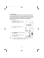
Maritime Radio Services Operation
Warning!
This transmitter will operate on channels/frequencies that have
restricted use in the United States. The channel assignments
include frequencies assigned for exclusive use of the U.S.
Coast Guard, use in Canada, and use in international waters.
Operation in these frequencies without proper authorization is
strictly forbidden. For frequencies/channels that are currently
for use in the U.S. without an individual license, please contact
the FCC Call Center at 1-888-CALL-FCC.
For individuals requiring a license, such as commercial users, you should obtain
a license application from your nearest FCC field office.
West Marine works to reduce lead content in our PVC coated cords in our
products and accessories.
WARNING: The cords on this product and/or accessories contain lead, a
chemical known to the State of California to cause birth defects or other
reproductive harm. Wash hands after handling.
UT01920ZZ_1
4/7/04
2:19 PM
Page 3
Contents
West Marine VHF500 .............................................................................5
Included with your VHF500 ....................................................................6
Controls and Indicators...........................................................................7
Installation.............................................................................................11
Choosing a Location ........................................................................11
Engine Noise Suppression ..............................................................13
Antenna Considerations ..................................................................13
Antenna Selection and Installation ..................................................13
Installing the VHF500 ......................................................................14
Operation ..............................................................................................15
Power On/Off...................................................................................15
Last Channel Memory .....................................................................15
Squelch............................................................................................16
Hailing and Distress Channel 16/Channel 9 Communications .......17
Marine Distress Procedure ..............................................................17
Triple Watch.....................................................................................18
Selecting a Channel .......................................................................18
Weather Channels ..........................................................................19
Entering Channel Numbers into Memory Scan...............................19
Memory Channel Scan ....................................................................20
Triple Watch Alert Scan ...................................................................20
Alert Scan ........................................................................................20
Weather Alert...................................................................................21
About S.A.M.E. Weather Alert .........................................................21
Setting the Transmit (TX) Power .....................................................23
Menu Operation ....................................................................................24
Digital Selective Calling (DSC)........................................................25
Distress............................................................................................25
Individual Call.............................................................................27
Group Call ..................................................................................28
All Ships Call ..............................................................................29
Position Request ........................................................................31
Position Send .............................................................................32
Standby ......................................................................................33
Call Wait.....................................................................................34
UT01920ZZ_1
4/7/04
2:19 PM
Page 4
Setup ...............................................................................................36
Alarm Clock ................................................................................36
Local Time Adjust.......................................................................39
Daylight Savings On/Off.............................................................40
Directory.....................................................................................41
FIPS ...........................................................................................45
Auto Channel Switch..................................................................48
Position Reply ............................................................................49
Channel Name ...........................................................................51
WHAM........................................................................................53
Group MMSI...............................................................................56
User MMSI .................................................................................57
System.............................................................................................59
Contrast......................................................................................59
Lamp Adjust ...............................................................................60
Key Beep ...................................................................................61
NMEA Technical Setup .........................................................................62
Optional Accessories ............................................................................62
VHF FM Marine Radio Telephone
Channel and Functions (USA Channels) ........................................63
Channel and Functions (International Channels) ...........................64
Channel and Functions (Canadian Channels) ................................65
NWR-SAME Event Code......................................................................66
Specification .........................................................................................67
Troubleshooting ....................................................................................68
Care and Maintenance .........................................................................70
Three Year Limited Warranty................................................................71
UT01920ZZ_1
4/7/04
2:19 PM
Page 5
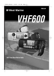
West Marine VHF500
The West Marine VHF500 is of all solid-state design with conservatively
rated, rugged components and materials compatible with the marine
environment. The transceiver utilizes a number of gaskets, sealing
rings, waterproof membranes, and other sealants to effect a waterproof
housing for protection of the electronics. It meets the most stringent
JIS7 waterproof specification. The unit may be mounted in any number
of convenient locations on your vessel by utilizing the optional flush
mount bracket (White - 500FMW, Black - 500FMB).
You are encouraged to thoroughly read the rest of this Operating Guide
to acquaint yourself with the characteristics and operation of your
transceiver so that you can contribute to the longevity of your
investment.
Keep your receipt as proof-of-purchase in case warranty service is
required.
Features, specifications, and availability of optional accessories are all
subject to change without notice.
Note:
VHF500 meets JIS7 requirements. This means that the radio
and mic are rated submersible to a depth of 1 meter for 30
minutes.
5
UT01920ZZ_1
4/7/04
2:19 PM
Page 6
Included with your VHF500
VHF500
Owner s Manual
VHF500 Radio
Mounting Bracket
and Knobs
Mounting Hardware
Microphone Hanger
and Screws
DC Cord
Accessory Cable
6
Spare Fuse
250V 6A
UT01920ZZ_1
4/7/04
2:19 PM
Page 7
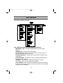
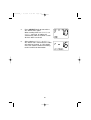
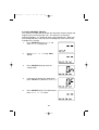
Controls and Indicators
Front panel/Microphone
3
2
4
5
67
8
11
12 13 14
9
1
10
1.
PTT Switch - Press to transmit and release to receive.
2.12. 16/9/TRI - Press this key briefly to instantly change to Channel 16,
Channel 9 or current channel. Press this key for more than two seconds to
activate the triple Watch Feature.
3.5. CH(CHANNEL)/▲(+)/▼(–) - These keys are used to change the channel
number up/down. These buttons are also used to move the cursor in
Menu mode.
SELECT - In the Menu mode this is used to select the menu options.
4.
MEM/UIC - Press this key briefly to place the currently selected channel
6.
into Memory. Press this key briefly again to delete the channel from
scanning memory. Press this key for more than two seconds to change
channel modes. (USA, International, or Canadian)
PA - Press this key briefly to enable the PA (Public Address) feature.
7.
PWR/VOL (On/Off/Volume) - Turns the unit On or Off and adjusts the
8.
speaker volume.
STEP/SCAN - Press this key briefly to activate the step operation. Every
9.
time this key is pushed, the radio will step to the next channel that has
been placed into Memory. Press this key for more than two seconds to
activate the memory channel scan feature.
10. H/L/MENU - Press this key briefly to change the transmit power to either
High (25 watts) or Low (1 watt). Press this key for more than two seconds
to enter the Menu mode.
11. WX/ALERT - Press this key briefly to listen to active NOAA Weather
channels. Press this key for more than two seconds to place the radio into
the Weather Alert mode.
13. DISTRESS - Lift the flap and press this key for 5 seconds to send a
distress signal in case of emergency.
14. SQUELCH - Rotate this knob clockwise to eliminate background noise
when a signal is not being received.
7
UT01920ZZ_1
4/7/04
2:19 PM
Page 8
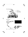
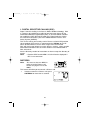
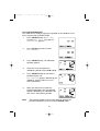
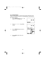
Rear Panel Connectors
1
1.
2.
3.
4.
2
3
4
ACC Connector
To VHF500
Note:
DC13.8V and GND are for GPS ANT.
8
DC Jack
ACC Connector
Remote Connector
Antenna Connector
UT01920ZZ_1
1.
2.
3.
4.
5.
6.
7.
8.
9.
10.
11.
12.
13.
14.
15.
16.
4/7/04
2:19 PM
Page 9
TX (Transmit) - Indicates transmitting.
HI (High) - Indicates transmit output is 25 Watts.
C - Indicates Canadian Channel Mode.
DSC - Indicates the radio is in the Digital Selective calling mode.
TRI (Triple Watch) - Indicates Triple Watch Mode is in effect.
MEM (Memory) - Indicates that the channel is entered into the
Scan memory.
(Alarm Icon) - It appears when the alarm clock is set.
LO (Low) - Indicates transmit output is 1 Watt.
U - Indicates USA Channel Mode.
I - Indicates International Channel Mode.
WX - Indicates Weather Channel Mode has been activated.
("ALT" Icon) - Indicates Weather Alert Mode has been
activated.
Radio Status Indicator - This area is used for Channel Name,
Menu, Frequency of active Weather Channel and messages
concerning SAME, DSC, and GPS. These messages will
continually scroll from right to the left.
(GPS Icon) - Indicates the radio is receiving data from an
external GPS.
(WHAM Icon) - Indicates the radio it is connected to the control
unit of the WHAM. (Wireless Handheld Access Microphone)
Channel Display - Indicates the current Channel Number.
9
UT01920ZZ_1
4/7/04
2:19 PM
Page 10
NOTES: "POS SEND", "LOCAL TIME ADJUST", "DAYLITE SAVINGS", and "ALARM
CLOCK" are not displayed in Menu when external GPS receiver is not
connected.
When the radio is in one of the following modes: WX Alert mode, Channel 16/9
mode, Scan Mode, or Triple Watch mode, and the user presses the Menu key, all
the of these modes are cancelled.
The Menu mode will be cancelled if the radio receives a DSC call or any key is
pressed besides the Up arrow, Down arrow, or select keys are pressed.
10
UT01920ZZ_1
4/7/04
2:19 PM
Page 11
Installation
Caution: The VHF500 will only operate with a nominal 12 volt negative
ground battery system.
Keep in mind the flexibility designed into the VHF500 so that you can
most conveniently use it. Features which should be considered are:
1.
The universal mounting bracket may be installed on either the top
or bottom of a shelf, on a bulkhead, or for overhead mounting.
2.
The REMOTE speaker wires can be used with an auxiliary
speaker.
3.
All connections are "plug-in" type for easy removal of the radio.
4.
By using the optional WHAM (Wireless Handheld Access
Microphone), the VHF 500 can be mounted completely out of the
way.
5.
Also optionally available is your choice of flush mount brackets
(White - 500FMW, Black - 500FMB).
Choosing a Location
Some important factors to consider in selecting the location for your
VHF500.
1.
The VHF500 is completely waterproof, but will last longer if
protected from spray and splash.
2.
Keep the battery leads as short as possible. Direct connection to
the battery is most desirable. If direct connection can not be
made with the supplied power lead, any extension should be
made with #12-14 AWG wire. Long extensions should use larger
gauge wire.
3.
Keep the antenna lead - in wire as short as possible. If you must
use a long lead - in wire as in the case of a sailboat masthead
antenna installation, we recommend you upgrade your lead - in
wire according to the following table:
RG-58 <20'
RG-8X <35'
RG-8U <60'
4.
Locate your antenna as high as possible and clear from metal
objects. The reliable range of coverage is a direct function of the
antenna height.
5.
Select a location that allows free air flow around the heat sink on
the rear of the radio.
11
UT01920ZZ_1
6.
4/7/04
2:19 PM
Page 12
Select a location well away from the ship’s compass. Auxiliary
speakers also should be located away from the compass.
12
UT01920ZZ_1
4/7/04
2:19 PM
Page 13
Engine Noise Suppression
Interference from the noise generated by the electrical systems of
engines is sometimes a problem with radios. The VHF500 has been
designed to be essentially impervious to ignition noise and alternator
noise. However, in some installations it may be necessary to take
measures to further reduce the effect of noise interference. The
VHF500 radio DC battery wires, antenna lead, and accessory cables
should be routed away from the engine and engine compartment, and
from power cabling carrying high currents.
In severe cases of noise interference, it may be necessary to install a
noise suppression kit. Contact your West Marine store or dealer from
whom you purchased the radio for more information.
Antenna Considerations
A variety of antennas are available from a number of quality suppliers.
In general, we recommend 8’ 6dB rated antennas for powerboats, and
4’ 3dB antennas for sailboats.
In general, communication range is increased by using a high-gain
antenna placed as high as possible above the water line. Antennas
should be located away from metal objects. Keep coax feed cables as
short as practical.
Antenna Selection and Installation
VHF500 has been designed to accomodate all of the popular marine
VHF antennas. However, the selection and the installation of the
antenna is the responsibility of the user or installer.
The FCC has determined that excessive radiation poses a health risk to
people near radio transmitting antennas. Therefore, the antenna used
with this radio should be installed using the following guidelines to insure
a suitable distance between the antenna and persons close by.
Small whip antennas (3 dB) or smaller should be installed keeping at
least three feet separation distance between the radiating element and
people.
Larger antennas (6 dB or 9 dB) should be installed keeping at least a six
foot separation distance.
No person should touch the antenna or come into the separation
distance when the radio is transmitting.
13
UT01920ZZ_1
4/7/04
2:19 PM
Page 14
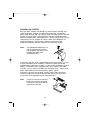
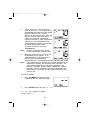
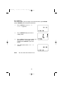
Installing the VHF500
After you have carefully considered the various factors affecting your
choice of location, position the radio (with the bracket, microphone,
power cord, antenna and any auxiliary cables installed) into the selected
location to assure there is no interference with the surrounding items.
Mark the location of the mounting bracket. Remove the bracket from the
radio and use it as a template to mark the holes to be drilled for the
mounting hardware. Drill the holes and mount the bracket with
hardware compatible with the material of the mounting surface.
Note:
This HEXAGON HEAD BOLT is
only for mounting the bracket
with hardware. Do not use it for
installing the radio in the
mounting bracket.
Connect the red wire of the supplied power cord to the positive (+) side
of your distribution circuit or battery. Connect the black wire of the
supplied power cord to the negative (–) side of your distribution circuit or
battery. The power cord is equipped with a fuse to protect the radio.
Use only a six (6) ampere fast blow fuse for replacement. Connect the
power cord to the keyed connector on the power "pigtail".
Connect the antenna and all other auxiliary cables and accessories.
Install the radio in the mounting bracket and connect all cables and
accessories to the appropriate jacks and connectors.
Note:
Do not use any other mounting
knobs than the ones enclosed.
Do not insert the knobs without
attaching the bracket.
14
UT01920ZZ_1
4/7/04
2:19 PM
Page 15
Operation
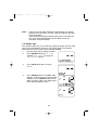
POWER On/Off
Turn the unit On by rotating the PWR/VOL
control clockwise. Adjust the volume to a
comfortable level.
When you turn the unit On, you will hear a
beep, and the greeting message below
appears on the Radio Status Display for 3
seconds.
Last Channel Memory
The VHF500 memorizes the last channel selected before you turn Off
the radio. For example, if you turn Off the radio on CH 12, it will be on
that channel when turned back On.
Note:
In order for the last channel to be memorized, you must have
the radio on that channel for 3 seconds.
15
UT01920ZZ_1
4/7/04
2:19 PM
Page 16
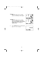
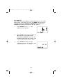
SQUELCH
Turn SQUELCH fully clockwise. This raises the “Squelch Gate” so high
that only very strong signals can get through.
Strong Signals
Medium Signals
Weak Signals
Noise
Turn SQUELCH fully counterclockwise until you hear a hiss. This lowers
the “Squelch Gate” so that everything gets through - noise, weak
signals, and strong signals.
Strong Signals
Medium Signals
Weak Signals
Noise
Turn SQUELCH back clockwise until the hiss stops. For best results,
adjust the squelch so that the noise is eliminated, but no further.
Strong Signals
Medium Signals
Weak Signals
Noise
16
UT01920ZZ_1
4/7/04
2:19 PM
Page 17
HAILING AND DISTRESS CHANNEL 16/CHANNEL 9
COMMUNICATIONS
To select Channel 16 or Channel 9, press the 16/9/TRI key. The first
press of the 16/9/TRI key will select the Hailing and Distress channel 16
instantly while tuned to another channel. A second of 16/9/TRI key will
select channel 9. Press 16/9/TRI briefly a third time to return to the
channel selected prior to accessing Hailing and Distress Channel
16/Channel 9 commnunications. The display will indicate the selected
channel.
To cancel Hailing and Distress Channel
16/Channel 9 communications:
● Press 16/9/TRI briefly until the
previous channel setting appears.
--or-● Press WX/ALERT, CH ▲, ▼ or STEP/SCAN briefly.
MARINE DISTRESS PROCEDURE
Speak slowly – clearly – calmly.
1.
Make sure your radio is On.
2.
Tune to Channel 16.
3.
Press the PTT button on the microphone and say: "MAYDAY –
MAYDAY – MAYDAY."
4.
Give your ship ID.
5.
Say "MAYDAY [your ship name]."
6.
Give your location: (what navigational aids or landmarks are
near).
7.
State the nature of your distress.
8.
Give the number of persons aboard and the conditions of any
injured.
9.
Estimate present seaworthiness of your vessel.
10. Give a brief description of your vessel (meters, type, color, hull).
11. Say: "I will be listening on Channel 16".
12. End message by saying "THIS IS [your ship name or call sign]
OVER."
13. Release the PTT button and listen. Someone should answer.
If not, repeat call, beginning at Item 3 above.
17
UT01920ZZ_1
4/7/04
2:19 PM
Page 18
TRIPLE WATCH
Triple Watch monitors Channel 16, Channel 9, and the current Marine
Channel (home or normal Channel) or Weather Channel.
To activate Triple Watch, Press 16/9/TRI for more than two seconds.
TRI appears on the Radio Status Display, indicating Triple Watch mode
is in effect. If a signal is received on either Channel 16 or Channel 9, the
radio remains on that channel until the signal ends.
Press 16/9/TRI for more than two seconds to cancel the Triple Watch mode.
Note:
While in Triple Watch mode, you can change the currently
selected channel using CH ▲ and ▼.
A momentary press of the 16/9/TRI button interrupts Triple
Watch mode and remains on channel 16, or on channel 9 if
you press 16/9/TRI briefly once more. To return to the Triple
Watch mode, simply press the button briefly again.
SELECTING A CHANNEL
To manually select a channel, press CH ▲ or ▼ briefly. Communication
channels are located on channel 01-28 and 60-88. Weather channels
are located on channels WX 0-9.
Note:
In the US, the Coast Guard may refer to Channels 21, 22, 23
etc. as 21 alpha, 22 alpha, etc. The VHF500 shows these
channels in the USA mode as channel 21, 22, 23, etc.
18
UT01920ZZ_1
4/7/04
2:19 PM
Page 19
WEATHER CHANNELS
To select Weather Channels 0-9, press
WX/ALERT briefly. The radio will go to the
last selected Weather Channel. Press CH ▲
or ▼ briefly to select a different Weather
Channel. Most areas of the US are covered by
Weather Channels 1,2, and 3.
To exit from Weather Channel:
● Press WX/ALERT briefly. The radio returns to the previous
Marine channel.
ENTERING CHANNEL NUMBERS INTO MEMORY SCAN
You can enter channels into the radio’s memory so they can be rapidly
scanned. This means that you can have the radio move from one
memorized channel to the next, and have it stop to monitor the channel
only if there is traffic, or conversations, on that channel.
To enter a channel into Memory Scan, select
the channel you want to store by using CH ▲
and ▼, and then press MEM/UIC briefly. The
channel is stored in Memory Scan and MEM
appears on the Radio Status Display.
To cancel the channel in Memory, press MEM/UIC. The MEM icon
disappears.
Note:
The Memory channel can be set independently in 3 regional
modes (USA, INT, and CAN). You cannot use this feature in
WX mode or for channel 70.
19
UT01920ZZ_1
4/7/04
2:19 PM
Page 20
MEMORY CHANNEL SCAN
This feature will allow you to scan only the channels of your choice.
Memory Channel Scan can only be activated if channels have previously
been placed into memory.
To turn on Memory Channel Scan, press and hold the STEP/SCAN key
for 2 seconds.
The VHF500 will now scan the channels that were previously placed into
memory, starting with the lowest channel number to the highest channel
number.
TRIPLE WATCH ALERT SCAN
This feature will allow you to listen to the channel of your choice. Scan
channels 16 and 9 every 2 seconds, and scan for Emergency or
Weather Alerts every seven seonds to be sure that you will not miss any
important broadcasts.
To turn Triple Watch Alert Scan On, press and hold WX/ALERT for
2 seconds while in Memory Channel Scan mode. While the Memory
Channels are scanned, Channel 16 and Channel 9 are scanned every 2
seconds, and the Weather Channel is scanned every 7 seconds. TRI
and
icon appear on the Radio Status Display.
ALERT SCAN
This feature will allow you to scan the channels of your choice and also
scan the Weather channels for Emergency or Weather alerts.
To turn Alert Scan On, press and hold WX/ALERT for 2 seconds. While
Memory Channels are scanned, the Weather Channel is scanned every
7 seconds. The
icon appears on the Radio Status Display.
20
UT01920ZZ_1
4/7/04
2:19 PM
Page 21
WEATHER ALERT
Weather Alert is a safety function that allows the radio to monitor the
local weather channel for NOAA Weather Alert broadcasts, while
allowing you to listen to other channels.
The traditional weather feature receives weather broadcasts (usually
within a 50-mile radius) then sounds an alarm if the emergency tone is
transmitted. This means that people who live outside an affected area
are often alerted even when their area is not affected, causing many of
them to ignore potentially real emergency/weather warnings that can
save lives.
ABOUT S.A.M.E. WEATHER ALERT
In 1994, the National Oceanic and Atmospheric Administration (NOAA)
began broadcasting coded signals called FIPS (Federal Information
Processing System) codes along with their standard weather
broadcasts. These codes identify an emergency and the specific
geographic area (such as a county) affected by the emergency.
The VHF500 was developed with the SAME (Specific Area Message
Encoding) technology. This allows your radio to receive, interpret, and
display the information about the codes so you can determine if the
emergency might affect your area.
Each FIPS code identifies a specific geographic area (defined by the
National Weather Service), so your radio sounds an alert only when an
emergency/weather emergency is declared in those locations. This
helps you more efficiently track the emergency/weather conditions in
and around your area.
When the VHF500 receives a weather alert:
• It sounds an alert siren.
• A description of the alert appears.
The alert descriptions your radio can display are based on a list of
specific weather alert types published by the NWS (National Weather
Service). For a list of all the alert descriptions that your radio can display.
Please see the NWR-SAME EVENT CODE section of this manual.
Caution:The NWS uses sophisticated weather models to determine an
alert’s effective time. However, the end of an alert does not
necessarily mean that the related weather emergency is over.
21
UT01920ZZ_1
4/7/04
2:19 PM
Page 22
The Weather Alert mode can be activated to alert you of dangerous
weather. When Weather Alert is turned On, and a warning signal is
received, an emergency siren will sound at full volume, regardless of the
volume setting. When the signal stops, you will hear the active weather
channel broadcast at the normal volume setting.
Note:
See SETUP mode to program up to 10 FIPS codes.
The
icon indicates the Weather Alert mode is activated. To activate
the Weather Alert mode:
1.
Press WX/ALERT for more than two
seconds when WX ALERT is Off.
The radio turns the WX ALERT On and
the
icon appears.
2.
If the radio receives a 1050Hz tone, the
icon will blink every other second
and the alert tone will ring.
In the area where SAME is
broadcasted, the following is displayed.
3.
When a WX ALERT signal is received,
all other functions are canceled and the
radio remains on the selected weather
channel.
When the radio is in Scan mode,
scanning the weather channel every 7
seconds, the SAME signal is not
decoded. To decode the SAME signal, the radio should be on an
active weather channel.
In order to stop the alert press any key briefly. If you press any
key briefly once more, the alert icon disappears.
Note:
The radio must be tuned to an active weather channel to
decode the SAME signal. This is necessary because the
SAME signal is only broadcast in the very beginning of the 10
second Weather alert tone by National Weather Service.
22
UT01920ZZ_1
4/7/04
2:19 PM
Page 23
SETTING THE TRANSMIT (TX) POWER
The VHF500 transmits on fifty-four marine frequencies and
receives on eighty marine frequencies. Channel 70 of the USA,
International, and Canadian frequencies, channel 15 of the USA
frequencies, and Weather Channels 0 - 9 – are for receiving only. The
radio transmits on channel 70 when sending DSC information. Your
radio will not transmit on these channels. For your reference, a listing of
all the available marine channels are located on pages 63 - 65.
Caution: It is important to remember to use the LO position in port or
for short range communications.
1.
When you turn the radio On for the first
time, the unit is automatically set to
transmit at 25 watts (HI).
2.
Press H/L/MENU briefly to change the
transmit output power to 1 watt (LO).
3.
Press H/L/MENU briefly again to change
back to 25 watts (HI).
Note:
A short tone sounds everytime you press the H/L/MENU.
CH13 is 1 watt (LO) channel. When the channel is LO power
channel, you can transmit at 25 watts (HI) by pressing
H/L/MENU during the call. LO power channels are USA
Channels 13, 17, 67, 77; Canadian Channels
13,15,17,20,66,70; INT Channel 15,17. Use low transmit power
in harbors or when close to the receiving station.You can not
change the transmit power setting on channels which are
receive-only channels: all weather channels; USA Channels 15,
70; Canadian Channel 70; International Channel 70.
23
UT01920ZZ_1
4/7/04
2:19 PM
Page 24
Menu Operation
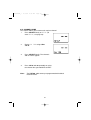
Flow Chart for Menu Operation
MENU
DSC CALL
SETUP
SYSTEM
INDIVIDUAL
ALARM CLOCK
CONTRAST
GROUP
LOCAL TIME ADJUST
LAMP ADJUST
ALL SHIPS
DAYLITE SAVE
KEY BEEP
POS REQUEST
DIRECTORY
EXIT
POS SEND
FIPS
STANDBY
AUTO CH SW
CALL WAIT
POS REPLY
EXIT
CH TAG
EXIT
WHAM
GROUP MMSI
USER MMSI
EXIT
The VHF500 includes the following DSC features:
INDIVIDUAL CALL - Quickly call other boats from your calling
directory.
GROUP CALL - Easily call a group of boats.
ALL SHIPS CALL - Allows you to send Urgent, Safety related, or
Routine calls to all ships in your area.
POSITION REQUEST - Easily request the position of a boat in your
call directory.
POSITION SEND - The ability to send your position information to a
boat in your call directory.
STANDBY - This allow your radio to acknowledge calls with
"Unavailable" while you are away from your boat.
CALL WAITING - Your VHF500 will automatically log into a directory
incoming calls for you to review at a later time if you are not available
to take the call immediately.
24
UT01920ZZ_1
4/7/04
2:19 PM
Page 25
1. DIGITAL SELECTIVE CALLING (DSC)
Digital Selective Calling is the latest in Marine Radio technology. DSC
is a process of establishing a radio call and has been chosen by the
International Maritime Organization (IMO) as an international standard
for establishing VHF, MF and HF radio calls. Digital Selective Calling
has also been selected as part of the Global Maritime Distress and
Safety System (GMDSS).
This service will let you instantly send a Distress call with GPS position
(when optional GPS receiver is connected to the VHF500) to the US
Coast Guard and other vessels within range of the transmission.
DSC will also let you initiate or receive distress, urgency, safety, position
information and routine calls to or from another vessel outfitted with a
DSC transceiver.
See the directory section for instructions on how to setup the directory of
names.
Note:
• Position SEND and ALARM CLOCK will not be displayed if
GPS is not connected.
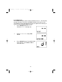
DISTRESS
Note:
You must set the user MMSI in
order to send a Distress call.
Please see page 57 to set the
MMSI.
This feature will allow you to transmit a Distress call.
1.
In order to transmit a Distress call, press
DISTRESS for more than 5 seconds.
25
UT01920ZZ_1
4/7/04
2:19 PM
Page 26
2.
The Distress call is transmitted and it
waits for about 210 - 270 seconds for an
acknowledgement from the Coast Guard
before the Distress call is resent.
After the Distress call has been sent, the
Distress alert will sound every other
second. The radio will automatically
change to channel 16, and it also watches
channel 70 in the background until an
acknowledgement signal is received from
the Coast Guard shore station.
To cancel the Distress call, press
16/9/TRI briefly.
Note:
Only the Coast Guard can electronically acknowledge a Distress call.
3.
When the radio receives a Distress call,
the following screen appears. If an
acknowledgment is not received, the
Distress call is repeated until an
acknowledgment is received from the Coast Guard shore station.
Note:
If the radio receives a Distress call, it will be displayed on the
Radio Status Display. An emergency alert will sound. The
name will be displayed if it is the name registered in the
directory. Otherwise, sender’s MMSI is displayed. Latitude,
longitude, and time information will also be displayed if the
GPS receiver is carried in the vessel that transmitted a DSC
Distress call.
To enter the MENU:
1.
Press H/L/MENU for more than two
seconds to enter the Menu Operation.
2.
Press SELECT briefly to enter DSC CALL.
DSC CALL has 7 options as follows:
To exit, select EXIT.
26
UT01920ZZ_1
4/7/04
2:19 PM
Page 27
1-A. INDIVIDUAL CALL
This feature allows the user to contact another boat and to automatically
switch the receiving DSC radio to desired channel.
1.
First you must select an open channel.
2.
Press SELECT briefly at DSC CALL.
3.
INDIVIDUAL appears.
Press SELECT briefly.
4.
Select the individual you want to contact
using CH ▲ and ▼.Press SELECT
briefly to transmit the individual DSC
signal.
5.
WAITING appears followed by the
individual you have selected, and the
radio use Channel 70 while transmitting.
6.
When you receive the individual
acknowledgment successfully,
WAITING will change to COMPLETED .
Both radios tune to the selected
channel. (example: choose channel 68,
then make the call, when the call is
successful both radios will be on
channel 68. You are now ready to talk
to the other person on this channel.
27
UT01920ZZ_1
4/7/04
Note:
2:19 PM
Page 28
If there is not any data registered in the directory you cannot
proceed to the 2nd step. See the SETUP section for directory,
setup instructions.
Select an open (unused) working channel first, then make the
call. After the acknowledgment, both radios tune to the
previously selected channel.
1-B. GROUP CALL
This function allows the user to contact a group of specific vessels using
DSC and to automatically switch to a desired channel. This function
allows you to transmit a DSC signal with group MMSI.
1.
First you must select an open channel.
2.
Press SELECT briefly at DSC CALL
(To enter DSC CALL, see page 26).
INDIVIDUAL appears.
3.
Press CH ▼ briefly once to select
GROUP.
4.
Press SELECT briefly. The MMSI code
appears, and you can now call the group
members. Press SELECT briefly to call.
When you finish calling, the radio returns
to the channel display screen.
28
UT01920ZZ_1
4/7/04
2:19 PM
Page 29
1-C. ALL SHIPS CALL
This radio has the ability to send 3 types of all ships calls. The following
are examples of what these types of calls would be used for:
Urgency - This call is for a vessel not yet in Distress, but may have
a serious problem.
Safety - This call is used for a reason like debris in the Water.
Routine - This call is used for normal calls.
1.
2.
Press SELECT briefly at DSC CALL
(To enter DSC CALL, see page 26).
INDIVIDUAL appears.
Press CH ▼ twice to select ALL
SHIPS.
3.
Press SELECT briefly. URGENCY
appears.
4.
Select the category of your call using
CH ▲ and ▼ (URGENCY, SAFETY,
ROUTINE).
Note:
ROUTINE calls tune to the
previously selected channel.
URGENCY and SAFTY calls tune to
channel 16.
29
UT01920ZZ_1
4/7/04
2:19 PM
Page 30
5.
Press SELECT briefly to transmit the
ALL SHIPS DSC signal.
When sending either an URGENCY or
SAFETY message, all radios will
automatically move to channel 70 until
all of the data is received.
6.
After selecting URGENCY or SAFETY
ALL SHIPS call is transmitted, the radio
will switch to Channel 16. You should
wait a few minutes before transmitting
the ALL SHIPS call information.
30
UT01920ZZ_1
4/7/04
2:19 PM
Page 31
1-D. POSITION REQUEST
This radio has the ability to request the position of an individual vessel
that is registered in the DIRECTORY.
1.
Press SELECT briefly at DSC CALL
(To enter DSC CALL, see page 26).
INDIVIDUAL appears.
2.
Press CH ▼ three times to select
POS REQUEST.
3.
Press SELECT briefly. The individual
directory appears.
4.
Select the name to request the
individual’s position using CH ▲ and ▼.
5.
Press SELECT briefly to transmit the
position request call.
POS WAITING appears followed by the
individual, and the radio use 70 CH
while transmitting.
6.
When the called vessel sends the
position information, time and position
appears followed by the individual. You
can see the time and the position.
Note:
The requested radio must have the ability to transmit the
position information (such as having a VHF500 radio).
31
UT01920ZZ_1
4/7/04
2:19 PM
Page 32
1-E. POSITION SEND
This radio has the ability to send the position of your vessel to another
vessel using a VHF marine radio equipped with DSC.
Note:
Position send is only available when it is connected to the
GPS.
1.
2.
Press SELECT briefly at DSC CALL
(To enter DSC CALL, see page 26).
INDIVIDUAL appears.
Press CH ▼ four times to select
POS SEND.
3.
Press SELECT briefly. The individual
directory appears.
4.
Press SELECT briefly to send your
position information.
5.
The following screen appears.
32
UT01920ZZ_1
4/7/04
2:19 PM
Page 33
1-F. STANDBY
The DSC STANDBY function allows the VHF500 to answer DSC calls
with the UNATTENDED message and record the calls for response at
another time. When you set the radio to DSC STANDBY mode, voice
traffic may still be active on any chosen channel.
1.
2.
Press SELECT briefly at DSC CALL
(To enter DSC CALL, see page 26).
INDIVIDUAL appears.
Press CH ▼ five times to select
STANDBY. Then times to select briefly.
3.
Note:
When an individual DSC call is received,
the radio will respond with the
UNATTENDED message when an
operator cannot answer the call. The
DSC call will be recorded into the radio’s
Call Waiting directory.
If you press a key on the radio or the PTT, this feature will be
canceled.
33
UT01920ZZ_1
4/7/04
2:19 PM
Page 34
1-G. CALL WAIT
The DSC Call Waiting directory records 10 received distress calls, and
records 20 individual calls that are received and not answered within 5
minutes or while the radio is set to DSC Standby. Calls will be recorded
while you are busy with other communications as long as the transmitter
is not keyed at the time of the call. If the call is answered within 5
minutes the call will not be recorded. When a call is recorded, a
message appears.
1.
2.
Press SELECT briefly at DSC CALL
(To enter DSC CALL, see page 26).
INDIVIDUAL appears.
Press CH ▼ repeatedly to select
CALL WAIT.
3.
Press SELECT briefly. The CALL WAIT
directory appears.
4.
Select the options you want to view
using CH ▲ and ▼.
Note:
If a call has not been logged, the radio will beep and you will
not be able to proceed to the next step.
34
UT01920ZZ_1
4/7/04
2:19 PM
Page 35
5.
Press SELECT briefly.
6.
If a DISTRESS call is received in Call
Wait, the following display appears.
If an INDIVIDUAL call is received in Call
Wait, the following display appears. At
this point, you can call back any of the
radios in the log.
7.
Press SELECT briefly. Received data
appears.
8.
Using CH ▲ and ▼ allows you to look
through all of the data. If you press
SELECT briefly, the radio starts
transmitting.
35
UT01920ZZ_1
4/7/04
2:19 PM
Page 36
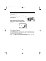
2. SETUP
1.
Press H/L/MENU for more than two
seconds to enter Menu Operation.
2.
Press CH ▼ once to display SETUP,
and press SELECT briefly.
SETUP has 9 options as follows. To exit, select EXIT.
2-A. ALARM CLOCK
This feature is only available when the GPS is connected to the
NMEA0183 Accessory Wires. If it is connected to the GPS, the alarms
are set based on the satellite. You need to set the time previously to
setting the alarm.
2-A-1. ALARM SET
This feature allows you to set the alarm.
1.
Press SELECT briefly at SETUP.
ALARM CLOCK appears.
2.
Press SELECT briefly.
3.
Press CH ▲ or ▼ to select On.
Then, press SELECT for more than two
seconds
4.
Select the hour using CH ▲ and ▼,
then press SELECT briefly.
5.
Select the minute using CH ▲ and ▼,
then press SELECT briefly.
36
UT01920ZZ_1
4/7/04
2:19 PM
Page 37
6.
Select AM or PM using CH ▲ or ▼, then
press SELECT briefly.
7.
A confirmation screen appears.
2-A-2. ALARM ON
This feature allows you to turn the alarm ON.
1.
Press SELECT briefly at SETUP
(To enter SETUP, see page 36).
2.
ALARM CLOCK appears. Then, press
SELECT briefly.
3.
Press SELECT briefly again.
4.
Select On. Using CH ▲ or ▼, and press
SELECT briefly. The radio returns to the
channel display screen and the
icon
appears.
5.
When the radio reaches the set time the
alarm sounds and the
icon blinks.
Note:
The alarm sounds when the set time is reached, you can turn
the alarm Off by pressing any key. Alarm mode will turn Off
automatically once the alarm sounds.
37
UT01920ZZ_1
4/7/04
2:19 PM
Page 38
2-A-3. ALARM OFF
This feature allows you to turn the alarm OFF.
1.
Press SELECT briefly at SETUP
(To enter SETUP, see page 36).
2.
ALARM CLOCK appears.
3.
Press SELECT briefly.
4.
Select OF using CH ▲ or ▼, then press
SELECT briefly.
5.
Press SELECT briefly. The radio returns
to the channel display screen and the
icon disappears.
38
UT01920ZZ_1
4/7/04
2:19 PM
Page 39
2-B. LOCAL TIME ADJUST
This feature allows you to fine tune the Local Time for any location in
North America. The feature enables you to adjust the Local time by ±1
hour.
To set LOCAL TIME ADJUST
1.
Press SELECT briefly at SETUP
(To enter SETUP, see page 36).
2.
Display LOCAL TIME ADJUST using
CH▲ and CH▼.
3.
Press SELECT briefly. The registering
screen appears. You can now adjust the
time for your local area using CH▲ and
CH▼.
4.
The time will be entered when you press
SELECT briefly. The display returns to
LOCAL TIME ADJUST screen.
39
UT01920ZZ_1
4/7/04
2:19 PM
Page 40
2-C. DAYLIGHT SAVINGS On/Off
This feature enables you to select the automatic Daylight Savings clock
setting.
To set DAYLIGHT SAVINGS On/Off
1.
Press SELECT briefly at SETUP (To
enter SETUP, see page 36).
2.
Display DAYLITE SAVE using CH▲
and CH▼.
3.
Press SELECT briefly. Then press CH▲
briefly to set DAYLIGHT SAVINGS on or
CH▼ to off (the default setting is off).
4.
Press SELECT briefly. The display
returns to DAYLITE SAVE screen.
40
UT01920ZZ_1
4/7/04
2:19 PM
Page 41
2-D. DIRECTORY
This function will allow you to send an individual call, etc. The Directory
function memorizes the name and MMSI number of 20 other vessels.
The following screen will allow you to setup an alphanumeric identity as
well as the corresponding MMSI number.
1.
Press SELECT briefly at SETUP
(To enter SETUP, see page 36).
2.
Display DIRECTORY using CH ▲
and ▼.
3.
Press SELECT briefly. The DIRECTORY
menu appears. Use CH ▲ and ▼ to
select the menu.
41
UT01920ZZ_1
4/7/04
2:19 PM
Page 42
2-D-1. NEW
This function will allow you to enter new information into the
directory.
1.
Press SELECT briefly at NEW. The
registering screen appears.
2.
You can now enter the person’s name.
Press CH ▲ repeatedly to choose the
alphabet. The character will be entered
when SELECT is pressed briefly is
pressed, and the blinking digit moves to
the right.
3.
After you enter the person’s name, you
can enter their MMSI number. Press CH
▲ briefly to increase the number, CH ▼
to decrease. The number will be entered
when SELECT is pressed briefly is
pressed, and the blinking digit will move
to the right.
4.
When you finish entering the last digit,
the radio returns to NEW screen.
42
UT01920ZZ_1
4/7/04
2:19 PM
Page 43
2-D-2. EDIT
If you want to edit the DIRECTORY
1.
Press SELECT briefly at the individual
you want to edit.
2.
EDIT appears, then press SELECT
briefly.
3.
You can now edit the person’s name.
Press CH ▲ repeatedly, and press
SELECT briefly to choose the alphabet.
4.
After you edit the person’s name, you
can edit the MMSI. Press CH ▲ to
increase the number, CH ▼ to decrease.
The number will be entered when
SELECT is pressed briefly and the
blinking digit moves to the right.
5.
After the directory data is edited, the
individual appears.
43
UT01920ZZ_1
4/7/04
2:19 PM
Page 44
2-D-3. DELETE
If you want to delete the directory
1.
Press SELECT briefly at the individual
you want to delete.
2.
Press CH ▼ once. DELETE appears,
then press SELECT briefly.
3.
The radio displays the next individual.
If no more code remains, EXIT
appears.
44
UT01920ZZ_1
4/7/04
2:19 PM
Page 45
2-E. FIPS
The 6-digit Federal Information Processing System (FIPS) code
established by the National Weather Service (NWS) identifies
geographic areas in the United States. Programming FIPS codes are
necessary to receive SAME alerts about weather occurring in a
particular area. To obtain the FIPS code for a particular area contact the
NWS toll free at 1-888-NWR-SAME (1-888-697-7263).
Or visit their website: http://www.nws.noaa.gov/nwr/indexnw.htm.
A list of event codes are located on page 66.
To set FIPS code
1.
Press SELECT briefly at SETUP
(To enter SETUP, see page 36).
2.
Display FIPS using CH ▲ and ▼.
3.
Press SELECT briefly. The FIPS menu
appears. Use CH ▲ and ▼ to select the
menu.
45
UT01920ZZ_1
4/7/04
2:19 PM
Page 46
2-E-1. NEW
If you want to register a new FIPS code
1.
Press SELECT briefly at NEW. The
registering screen appears.
2.
You can now enter the new FIPS code.
Press CH ▲ to increase the number,
CH ▼ to decrease. The number will be
entered when SELECT is pressed
briefly, and the blinking digit moves to
the right. When you finish entering the
last digit, the radio returns to NEW
screen.
2-E-2. EDIT
If you want to edit the FIPS code
1.
Press SELECT briefly at the code that
you want to edit.
2.
EDIT appears, then press SELECT
briefly.
3.
You can now edit the FIPS code. Press
CH ▲ increase the number, CH ▼ to
decrease. The number will be entered
when SELECT is pressed briefly, and
the blinking digit moves to the right.
46
UT01920ZZ_1
4.
4/7/04
2:19 PM
Page 47
When you finished editing the last digit,
the confirmation screen appears.
2-E-3. DELETE
If you want to delete a directory entry
1.
Press SELECT briefly at the code that
you want to delete.
2.
Press CH ▼ once. DELETE appears,
then press SELECT briefly.
3.
The radio displays the next code.
If no more code remains, EXIT
appears.
47
UT01920ZZ_1
4/7/04
2:19 PM
Page 48
2-F. AUTO CHANNEL SWITCH
This feature is to allow you to disable the automatic channel change that
happens when receiving a DSC call. This feature is useful when
engaged in bridge – to – bridge or other safety related calls. When you
have completed these calls, all of the incoming DSC calls received are
available in the call log.
1.
Press SELECT briefly at SETUP (To
enter SETUP, see page 36).
2.
Display AUTO CH SW using CH ▲
and ▼.
3.
Press SELECT briefly to enter the
setting mode.
4.
If you want to change this mode to off,
press CH ▼ once. (Default is set as ON.)
5.
Press SELECT briefly. The radio returns
to the AUTO CH SW screen.
48
UT01920ZZ_1
4/7/04
2:19 PM
Page 49
2-G. POSITION REPLY
When the calling radio has requested the position information of your
radio, you can decide to transmit an acknowledgment automatically or
on a call by call basis.
1.
Press SELECT briefly at SETUP (To
enter SETUP, see page 36).
2.
Display POS REPLY using CH ▲
and ▼.
3.
Press SELECT briefly to enter the
setting mode.
4.
Press CH ▲ or ▼ to make your
selection.
49
UT01920ZZ_1
4/7/04
2:19 PM
Page 50
Example: On
When the radio receives a position
request, the following screen appears.
Example: OF
When the radio receives a position
request, the following screen appears.
You can select whether reply the request
or not. If you wants to reply press
SELECT briefly.
5.
Press SELECT briefly. The radio returns
to the POS REPLY screen.
50
UT01920ZZ_1
4/7/04
2:19 PM
Page 51
2-H. CHANNEL NAME
This feature allows you to name each marine channel.
1.
Press SELECT briefly at SETUP (To
enter SETUP, see page 36).
2.
Display CH TAG using CH ▲
and ▼.
3.
Press SELECT briefly. The channels
and its names appear.
4.
Press CH ▲ and ▼ repeatedly to select
the channel that you would like to EDIT.
Note:
The VHF500 radio comes pre-programmed with default
channel names.
51
UT01920ZZ_1
4/7/04
2:19 PM
Page 52
2-H-1. EDIT
If you want to edit the channel name
1.
Press SELECT briefly at the individual
channel you want to edit.
2.
You can edit the name. Press CH ▲ or
▼ to select the alphabet, numeric, or
symbols. The character will be entered
when SELECT is pressed briefly, and
the blinking digit moves to the right.
3.
Press SELECT for more than two
seconds when you enter the last digit.
52
UT01920ZZ_1
4/7/04
2:19 PM
Page 53
2-I. WHAM (Wireless Handheld Access Microphone)
This feature, from the setup menu, will allow you to connect the WHAM.
Note:
When you use the WHAM in addition to the VHF500 wired mic,
please set the BASE ID for the WHAM the same as your
VHF500. (Please refer to the Owner’s Manual for the WHAM).
1.
Press SELECT briefly at SETUP (To
enter SETUP, see page 36).
2.
Display WHAM using CH ▲
and ▼.
3.
Press SELECT briefly. BASE ID
appears.
53
UT01920ZZ_1
4/7/04
2:19 PM
Page 54
2-I-1. BASE ID
This number consist of 4 digits that you decide yourself. This feature
allows you to set the Base ID. To use the WHAM, you must set the
same Base ID for your VHF500 and WHAM, which enables your
VHF500 and WHAM to communicate with one another.
1.
Press SELECT at BASE ID, the
following screen appears.
2.
Press CH ▲ to increase the number, CH
▼ to decrease. The number will be
entered when SELECT is pressed, and
the blinking digit moves to the right. (You
can select the number 0000 to 9999.)
3.
Press SELECT for more than two
seconds to enter the last digit. The radio
returns to the BASE ID screen.
54
UT01920ZZ_1
4/7/04
2:19 PM
Page 55
2-I-2. LINK CH
This feature allows you to change the channel between your VHF500
and the WHAM if you encounter interference.
1.
Press CH ▼ once at BASE ID.
LINK CH appears.
2.
Press SELECT briefly to enter the
editing mode.
3.
Press CH ▲ to increase the number, CH
▼ to decrease. The number will be
entered when SELECT is pressed
briefly.
4.
The radio returns to the LINK CH
screen.
Note:
You can select the channel 01-20.
55
UT01920ZZ_1
4/7/04
2:19 PM
Page 56
2-J. GROUP MMSI
Group MMSI is the Group ID to contact a group of specific vessels using
DSC and to automatically switch to a desired channel. This function
allows you to transmit a DSC signal with group MMSI.
1.
Press SELECT briefly at SETUP (To
enter SETUP, see page 36).
2.
Display GROUP MMSI using CH ▲
and ▼.
3.
Press SELECT briefly. The group MMSI
ID screen appears.
4.
You can now enter the GROUP MMSI code. Press CH ▲ to
increase the number, CH ▼ to decrease. The number will be
entered when SELECT is pressed briefly, and the blinking digit
moves to the right.
5.
After the final digit is entered, a
confirmation screen appears. Press
SELECT briefly and the radio returns to
the following screen.
56
UT01920ZZ_1
4/7/04
2:19 PM
Page 57
2-K. USER MMSI
Federal MMSI's are issued by the National Telecommunications and
Information Administration. Non-Federal MMSI's are issued by the
Federal Communications Commission (FCC). You will need to obtain a
nine digit MMSI number and program it into the VHF500. The
information obtained from the application is useful to the U.S. Coast
Guard to help in search and rescue operations. To obtain an MMSI
number, contact your authorized West Marine store or dealer from whom
you purchased the radio or visit one of the following websites:
www.boatus.com/mmsi/, http://wireless.fcc.gov/marine/fctsht14.html.
This portion of the SETUP menu will allow you to program an MMSI,
(Maritime Mobile Service Identity) for sending and receiving DSC calls.
To set USER MMSI code
1.
Press SELECT briefly knob at SETUP.
2.
Press CH ▼ eight times to select
USER MMSI.
3.
Press SELECT briefly. The user MMSI
ID screen appears.
57
UT01920ZZ_1
4/7/04
2:19 PM
Page 58
4.
You can now enter the USER MMSI
code. Press CH ▲ to increase the
number, CH ▼ to decrease. The number
will be entered when SELECT is
pressed briefly, and the blinking moves
to the right.
5.
After the final digit is entered. Press
SELECT for more than two seconds.
The radio returns to USER MMSI
screen.
Note:
You can only program your radio
twice with an MMSI number. After
that, send your radio to West Marine
for factory service.
58
UT01920ZZ_1
4/7/04
2:19 PM
Page 59
3. SYSTEM
1.
Press H/L/MENU for more than two
seconds to enter Menu Operation.
2.
Press CH ▼ twice to display SYSTEM,
and press SELECT briefly.
SYSTEM has 3 options as follows. To exit,
select EXIT.
3-A. CONTRAST
1.
Press SELECT briefly at SYSTEM.
CONTRAST appears.
2.
Press SELECT briefly to enter the
setting mode. (Default is set at 7).
3.
Press CH ▲ and ▼ to increase or
decrease the contrast level.
4.
When you find the most favorable
contrast, press SELECT briefly. The
radio returns to the CONTRAST screen.
If you want to exit the setting screen
without changing the contrast, press
H/L/MENU briefly.
Note:
There are 40 contrast levels (0 - 7).
59
UT01920ZZ_1
4/7/04
2:19 PM
Page 60
3-B. LAMP ADJUST
1.
Press SELECT briefly at SYSTEM.
(To enter SYSTEM, see page 59.)
2.
Press CH ▼ once to select LAMP
ADJUST.
3.
Press SELECT briefly to enter the
setting mode. (Default is set at 3).
4.
Press CH ▲ and ▼ briefly to select the
backlight brightness level.
5.
When you find the most favorable
brightness, press the SELECT briefly.
The radio returns to the LAMP ADJUST
screen.
Note:
The backlight settings are off, Level 1
Dim, Level 2 medium, and Level 3
bright.
60
UT01920ZZ_1
4/7/04
2:19 PM
Page 61
3-C. KEY BEEP
1.
Press SELECT briefly at SYSTEM.
(To enter SYSTEM, see page 59.)
2.
Press CH ▼ twice to select KEY BEEP.
3.
Press SELECT briefly to enter the
setting mode.
4.
Press CH ▲ and ▼ briefly to select ON
or OFF.
5.
Press SELECT briefly. The radio returns
to the KEY BEEP screen.
61
UT01920ZZ_1
4/7/04
2:19 PM
Page 62
NMEA Technical Setup
VHF500 NMEA0183 GPS Input Connection Specification
This section is useful when attaching an external GPS to the VHF500
radio. Many GPS units have a setup menu to be able to configure the
NMEA0183 serial data output. This output can be used to supply
information to other devices on the vessel, such as the VHF500 DSC
VHF radio, auto pilots, chart plotters, etc.
To setup the GPS to be used with the VHF500 radio, the following items
need to be considered for proper operation:
1.
Baud Rate – Set the Baud rate to 4800.
2.
Data Bits – Set the Data Bits to 8.
3.
Parity – Set the Parity to None.
4.
Stop Bits – Set the Stop Bits to 1.
5.
GPRMC Command – This command is used by the VHF500 and
includes the UTC Time, Latitude, Longitude, Speed, Direction, and
Date information.
The data amplitude : Over 3.0V
Drive capability
: Over 10mA
Optional Accessories
• Flush mounting bracket for “in dash” installation.
(White = 500FMW, Black = 500FMB)
Contact your West Marine store or dealer from whom you purchased the
radio for information.
62
UT01920ZZ_1
4/7/04
2:19 PM
Page 63
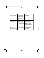
VHF FM Marine Radio Telephone
Channel and Functions
(USA Channels)
CHANNEL
DESIG
WX0
WX1
WX2
WX3
WX4
WX5
WX6
WX7
WX8
WX9
01
02
03
04
05
06
07
08
09
10
11
12
13
14
15
16
17
18
19
20
21
22
23
24
25
26
27
28
60
61
62
63
64
65
66
67
68
69
70
71
72
73
74
77
78
79
80
81
82
83
84
85
86
87
88
FREQUENCY (MHz)
TRANSMIT RECEIVE
TYPE OF
TRAFFIC
SHIP
TO SHIP
SHIP
TO SHORE
CH
Name
—
—
—
—
—
—
—
—
—
—
156.050
163.275
162.550
162.400
162.475
162.425
162.450
162.500
162.525
161.650
161.775
156.050
NOAA Weather
NOAA Weather
NOAA Weather
NOAA Weather
NOAA Weather
NOAA Weather
NOAA Weather
NOAA Weather
Can. Weather
Can. Weather
VTS
RX Only
RX Only
RX Only
RX Only
RX Only
RX Only
RX Only
RX Only
RX Only
RX Only
Yes
RX Only
RX Only
RX Only
RX Only
RX Only
RX Only
RX Only
RX Only
RX Only
RX Only
Yes
VTS/COML
156.150
156.150
Port Ops
Yes
Yes
CG ONLY
156.250
156.300
156.350
156.400
156.450
156.500
156.550
156.600
156.650
156.700
—
156.800
156.850
156.900
156.950
157.000
157.050
157.100
157.150
157.200
157.250
157.300
157.350
157.400
156.250
156.300
156.350
156.400
156.450
156.500
156.550
156.600
156.650
156.700
156.750
156.800
156.850
156.900
156.950
157.000
157.050
157.100
157.150
161.800
161.850
161.900
161.950
162.000
VTS
Safety
Com’l
Com’l
Com’l & Non Com’l
Com’l
Com’l
Port Ops
Navigational, TX 1W only
Port Ops
Environmental
Safety Calling
State Control
Com’l
Com’l
Port Ops, RX Duplex
Coast Guard
Coast Guard
Coast Guard
Public Corresp,Duplex
Public Corresp,Duplex
Public Corresp,Duplex
Public Corresp,Duplex
Public Corresp,Duplex
Yes
Yes
Yes
Yes
Yes
Yes
Yes
Yes
Yes
Yes
RX Only
Yes
Yes
Yes
Yes
Yes
Yes
Yes
Yes
No
No
No
No
No
Yes
No
Yes
No
Yes
Yes
Yes
Yes
Yes
Yes
RX Only
Yes
Yes
Yes
Yes
Yes
Yes
Yes
Yes
Yes
Yes
Yes
Yes
Yes
VTS/COML
SAFETY
COMMERCIAL
COMMERCIAL
NON COML
COMMERCIAL
VTS
VTS
BRG-BRG
VTS
ENVIRON
DISTRESS
GOVT
COMMERCIAL
COMMERCIAL
PORT OPR
CG ONLY
CG
CG ONLY
MAR OPER
MAR OPER
MAR OPER
MAR OPER
MAR OPER
156.075
156.075
156.175
156.225
156.275
156.325
156.375
156.425
156.475
156.525
156.575
156.625
156.675
156.725
156.875
156.925
156.975
157.025
157.075
157.125
157.175
157.225
157.275
157.325
157.375
157.425
156.175
156.225
156.275
156.325
156.375
156.425
156.475
156.525
156.575
156.625
156.675
156.725
156.875
156.925
156.975
157.025
157.075
157.125
157.175
161.825
161.875
161.925
161.975
157.425
CG
Port Ops
Port Ops
Com’l, TX 1W only
Non Com’l
Non Com’l
Yes
Yes
Yes
Yes
Yes
Yes
Yes
No
Yes
Yes
Non Com’l
Non Com’l
Port Ops
Port Ops
Port Ops
Non Com’l
Com’l
Com’l
Coast Guard
US Govt Only
Coast Guard
Public Corresp,Duplex
Public Corresp,Duplex
Public Corresp,Duplex
Public Corresp,Duplex
Com’l
Yes
Yes
Yes
Yes
Yes
Yes
Yes
Yes
Yes
Yes
Yes
No
No
No
No
Yes
Yes
No
Yes
Yes
No
Yes
Yes
Yes
Yes
Yes
Yes
Yes
Yes
Yes
Yes
No
63
VTS
COMMERCIAL
PORT OPR
PORT OPR
BRG-BRG
NON COML
NON COML
DSC
NON COML
NON COML
PORT OPR
PORT OPR
PORT OPR
NON COML
COMMERCIAL
COMMERCIAL
USCG
USCG
USCG
MAR OPER
MAR OPER
MAR OPER
MAR OPER
COMMERCIAL
UT01920ZZ_1
4/7/04
2:19 PM
Page 64
VHF FM Marine Radio Telephone
Channel and Functions
(International Channels)
CHANNEL
DESIG
WXO
WX1
WX2
WX3
WX4
WX5
WX6
WX7
WX8
WX9
01
02
03
04
05
06
07
08
09
10
11
12
13
14
15
16
17
18
19
20
21
22
23
24
25
26
27
28
60
61
62
63
64
65
66
67
68
69
70
71
72
73
74
77
78
79
80
81
82
83
84
85
86
87
88
FREQUENCY (MHz)
TRANSMIT RECEIVE
—
—
—
—
—
—
—
—
—
—
156.050
156.100
156.150
156.200
156.250
156.300
156.350
156.400
156.450
156.500
156.550
156.600
156.650
156.700
156.750
156.800
156.850
156.900
156.950
157.000
157.050
157.100
157.150
157.200
157.250
157.300
157.350
157.400
156.025
156.075
156.125
156.175
156.225
156.275
156.325
156.375
156.425
156.475
156.525
156.575
156.625
156.675
156.725
156.875
156.925
156.975
157.025
157.075
157.125
157.175
157.225
157.275
157.325
157.375
157.425
163.275
162.550
162.400
162.475
162.425
162.450
162.500
162.525
161.650
161.775
160.650
160.700
160.750
160.800
160.850
156.300
160.950
156.400
156.450
156.500
156.550
156.600
156.650
156.700
156.750
156.800
156.850
161.500
161.550
161.600
161.650
161.700
161.750
161.800
161.850
161.900
161.950
162.000
160.625
160.675
160.725
160.775
160.825
160.875
160.925
156.375
156.425
156.475
156.525
156.575
156.625
156.675
156.725
156.875
161.525
161.575
161.625
161.675
161.725
161.775
161.825
161.875
161.925
161.975
162.025
TYPE OF
TRAFFIC
SHIP
TO SHIP
SHIP
TO SHORE
NOAA Weather
NOAA Weather
NOAA Weather
NOAA Weather
NOAA Weather
NOAA Weather
NOAA Weather
NOAA Weather
Can. Weather
Can. Weather
VTS,Duplex
Port Ops,Duplex
Port Ops,Duplex
Port Ops,Duplex
VTS,Duplex
Safety
Com’,Duplexl
Com’l
Com’l & Non Com’l
Com’l
Com’l
Port Ops
Navigational
Port Ops
Environmental
Safety Calling
State Control
Com’l,Duplex
Com’l,Duplex
Port Ops,Duplex
Coast Guard,Duplex
Coast Guard,Duplex
Coast Guard,Duplex
Public Corresp,Duplex
Public Corresp,Duplex
Public Corresp,Duplex
Public Corresp,Duplex
Public Corresp,Duplex
Duplex
Duplex
Duplex
Duplex
Duplex
Port Ops,Duplex
Port Ops,Duplex
Com’l
Non Com’l
Non Com’l
RX Only
RX Only
RX Only
RX Only
RX Only
RX Only
RX Only
RX Only
RX Only
RX Only
Yes
Yes
Yes
Yes
Yes
Yes
Yes
Yes
Yes
Yes
Yes
Yes
Yes
Yes
Yes
Yes
Yes
Yes
Yes
Yes
Yes
Yes
Yes
No
No
No
No
No
RX Only
RX Only
RX Only
RX Only
RX Only
RX Only
RX Only
RX Only
RX Only
RX Only
Yes
Yes
Yes
Yes
Yes
No
Yes
No
Yes
Yes
Yes
Yes
Yes
Yes
Yes
Yes
Yes
Yes
Yes
Yes
Yes
Yes
Yes
Yes
Yes
Yes
Yes
Yes
Yes
Yes
Yes
Yes
Yes
Yes
No
Yes
Yes
Non Com’l
Non Com’l
Port Ops
Port Ops
Port Ops
Non Com’l,Duplex
Com’l,Duplex
Com’l,Duplex
Coast Guard,Duplex
US Govt Only,Duplex
Coast Guard,Duplex
Public Corresp,Duplex
Public Corresp,Duplex
Public Corresp,Duplex
Public Corresp,Duplex
Com’l,Duplex
Yes
Yes
Yes
Yes
Yes
Yes
Yes
Yes
Yes
Yes
Yes
No
No
No
No
Yes
Yes
No
Yes
Yes
No
Yes
Yes
Yes
Yes
Yes
Yes
Yes
Yes
Yes
Yes
No
64
CH
Name
MAR OPER
MAR OPER
MAR OPER
MAR OPER
MAR OPER
SAFETY
MAR OPER
COMMERCIAL
CALLING
COMMERCIAL
VTS
VTS
BRG-BRG
VTS
ENVIRON
DISTRESS
GOVT
PORT OPR
COMMERCIAL
PORT OPR
PORT OPR
PORT OPR
MAR OPER
MAR OPER
MAR OPER
MAR OPER
MAR OPER
MAR OPER
MAR OPER
MAR OPER
MAR OPER
MAR OPER
MAR OPER
MAR OPER
MAR OPER
BRG-BRG
NON COML
NON COML
DSC
NON COML
NON COML
PORT OPR
PORT OPR
PORT OPR
PORT OPR
PORT OPR
PORT OPR
PORT OPR
PORT OPR
PORT OPR
MAR OPER
MAR OPER
MAR OPER
MAR OPER
MAR OPER
UT01920ZZ_1
4/7/04
2:19 PM
Page 65
VHF FM Marine Radio Telephone
Channel and Functions
(Canadian Channels)
CHANNEL
DESIG
WXO
WX1
WX2
WX3
WX4
WX5
WX6
WX7
WX8
WX9
01
02
03
04
05
06
07
08
09
10
11
12
13
14
15
16
17
18
19
20
21
22
23
24
25
26
27
28
60
61
62
63
64
65
66
67
68
69
70
71
72
73
74
77
78
79
80
81
82
83
84
85
86
87
88
FREQUENCY (MHz)
TRANSMIT RECEIVE
—
—
—
—
—
—
—
—
—
—
156.050
156.100
156.150
156.200
156.250
156.300
156.350
156.400
156.450
156.500
156.550
156.600
156.650
156.700
156.750
156.800
156.850
156.900
156.950
157.000
157.050
157.100
157.150
157.200
157.250
157.300
157.350
157.400
156.025
156.075
156.125
—
156.225
156.275
156.325
156.375
156.425
156.475
156.525
156.575
156.625
156.675
156.725
156.875
156.925
156.975
157.025
157.075
157.125
157.175
157.225
157.275
157.325
157.375
157.425
163.275
162.550
162.400
162.475
162.425
162.450
162.500
162.525
161.650
161.775
160.650
160.700
160.750
156.200
156.250
156.300
156.350
156.400
156.450
156.500
156.550
156.600
156.650
156.700
156.750
156.800
156.850
156.900
156.950
161.600
157.050
157.100
161.750
161.800
161.850
161.900
161.950
162.000
160.625
156.075
156.125
—
156.225
156.275
156.325
156.375
156.425
156.475
156.525
156.575
156.625
156.675
156.725
156.875
156.925
156.975
157.025
157.075
157.125
157.175
161.825
161.875
161.925
161.975
162.025
TYPE OF
TRAFFIC
SHIP
TO SHIP
NOAA Weather
NOAA Weather
NOAA Weather
NOAA Weather
NOAA Weather
NOAA Weather
NOAA Weather
NOAA Weather
Can. Weather
Can. Weather
Duplex
Duplex
Duplex
1W
1W
1W
Duplex, 1W
Duplex
Duplex
Duplex
Duplex
Duplex
Duplex
Duplex
SHIP
TO SHORE
RX Only
RX Only
RX Only
RX Only
RX Only
RX Only
RX Only
RX Only
RX Only
RX Only
Yes
Yes
Yes
Yes
Yes
Yes
Yes
Yes
Yes
Yes
Yes
Yes
Yes
Yes
Yes
Yes
Yes
Yes
Yes
Yes
Yes
Yes
Yes
No
No
No
No
No
RX Only
RX Only
RX Only
RX Only
RX Only
RX Only
RX Only
RX Only
RX Only
RX Only
Yes
Yes
Yes
Yes
Yes
No
Yes
No
Yes
Yes
Yes
Yes
Yes
Yes
Yes
Yes
Yes
Yes
Yes
Yes
Yes
Yes
Yes
Yes
Yes
Yes
Yes
Yes
Yes
Yes
Yes
Yes
Yes
Yes
Yes
No
Yes
Yes
Yes
Yes
Yes
Yes
Yes
Yes
Yes
Yes
Yes
Yes
Yes
No
No
No
No
Yes
Yes
No
Ye
Ye
No
Yes
Yes
Yes
Yes
Yes
Yes
Yes
Yes
Yes
Yes
No
Simplex
Duplex
Duplex
Duplex
Duplex
Duplex
65
CH
Name
MAR OPER
MAR OPER
MAR OPER
CCG
VTS
SAFETY
COMMERCIAL
COMMERCIAL
CALLING
COMMERCIAL
VTS
VTS
BRG-BRG
VTS
ENVIRON
DISTRESS
SAR
COMMERCIAL
CCG
PORT OPR
CCG
CCG
CCG
MAR OPER
MAR OPER
MAR OPER
MAR OPER
MAR OPER
MAR OPER
CCG
CCG
MAR OPER
RESCUE
PORT OPR
BRG-BRG
NON COML
NON COML
DSC
NON COML
NON COML
PORT OPR
PORT OPR
PORT OPR
SHIP-SHIP
SHIP-SHIP
SHIP-SHIP
CCG
CCG
CCG
MAR OPER
MAR OPER
MAR OPER
MAR OPER
MAR OPER
UT01920ZZ_1
4/7/04
2:19 PM
Page 66
NWR-SAME EVENT CODE
Event Code
Emergency Action Notification
Emergency Action Termination
National Information Center
Tornado Warning #
Severe Thunderstorm Warning #
Flash Flood Warning
Flood Warning
Winter Storm Warning
Blizzard Warning
High Wind/Dust Storm Warning
Radiological Hazard Warning
Civil Danger Warning
Local Area Emergency
Hazardous Material Warning
Civil Emergency Message
Immediate Evacuation Warning
Immediate Evacuation Notice
Law Enforcement Warning
Fire Warning
Hurricane/Tropical Storm Warning
Tsunami Warning
Coastal Flood Warning
Special Marine Warning
Avalanche Warning
Volcano Warning
Shelter In Place Warning
Child Abduction Emergency
Dust Storm Warning
Earthquake Warning
911 Telephone Outage Emergency
Nuclear Power Plant Warning
Tropical Storm Warning
Nuclear Power Plant Warning
Nuclear Power Plant Warning
Dam Break Warning
Civil Danger Watch
Radiological Hazard Watch
Hazardous Material Watch
Winter Storm Watch
High Wind/Dust Storm Watch
Tornado Watch
Severe Thunderstorm Watch
Flash Flood Watch
Flood Watch
Hurricane/Tropical Storm Watch
Tsunami Watch
Coastal Flood Watch
Avalanche Watch
Volcano Watch
Tropical Storm Watch
Dust Storm Watch
Earthquake Watch
Severe Weather Statement
Special Weather Statement
Flash Flood Statement
Flood Statement
Hurricane Statement
Administrative Message
Network Message Notification
Missing Child Statement
School Closing Statement
National Periodic Test
Required Monthly Test
Required Weekly Test
Nuclear Power Plant Test Message
System Demonstration/Practice
NATIONAL HAZARD WARNING
UNKNOWN EMERGENCY TUNE TV
UNKNOWN WARNING TUNE TV
UNKNOWN WATCH TUNE TV
UNKNOWN STATEMENT TUNE TV
Standard
EAN
EAT
NIC
TOW (or TOR)
SVW (or SVR)
FFW
FLW
WSW
BZW
HWW
RHW
CDW
LAE
HMW
CEM
IEW
EVI
LEW
FRW
HUW
TSW
CFW
SMW
AVW
VOW
SPW
CAE
DSW
EQW
TOE
NUW
TRW
NPW
NPP
DBW
CDA
RHA
HMA
WSA
HWA
TOA
SVA
FFA
FLA
HUA
TSA
CFA
AVA
VOA
TRA
DSA
EQA
SVS
SPS
FFS
FLS
HLS
ADR
NMN
MIS
SCS
NPT
RMT
RWT
NPM
DMO
NHW
**E
**W
**A
**S
Warning
0
0
0
0
0
0
0
0
0
0
0
0
0
0
0
0
0
0
0
0
0
0
0
0
0
0
0
0
0
0
0
0
0
0
0
EVENT LEVEL (Siren Type)
Watch
Statement
Test
0
0
0
0
0
0
0
0
0
0
0
0
0
0
0
0
0
0
0
0
0
0
0
0
0
0
0
0
0
0
0
0
0
0
0
66
Radio Status
Display
EMG NOTIFY
EMG END
NATION INFO
TORNADO
THUNDERSTORM
FLASH FLOOD
FLOOD
WINTER STORM
BLIZZARD
HIGH WIND
RADIOLOGICAL
CIVILDANGER
LOCAL EMG
HAZARDOUS
CIVIL EMG
EVACUATION
EVACUATENOTE
LAW ENFORCE
FIRE
HURRICANE
TSUNAMI
COAST FLOOD
SPECIAL MRN
AVALANCHE
VOLCANO
SHELTER
CHILD EMG
DUST STORM
EARTHQUAKE
911 OUTAGE
NUCLEAR
TROPIC STORM
NUCLEAR
NUCLEAR
DAM BREAK
CIVIL DANGER
RADIOLOGICAL
HAZARDOUS
WINTER STORM
HIGH WIND
TORNADO
THUNDERSTORM
FLASH FLOOD
FLOOD
HURRICANE
TSUNAMI
COAST FLOOD
AVALANCHE
VOLCANO
TROPIC STORM
DUST STORM
EARTHQUAKE
SEVERE WX
SPECIAL WX
FLASH FLOOD
FLOOD
HURRICANE
ADMIN MSG
NETWORK MSG
MISS CHILD
SCHOOL CLOSE
NATIONPERIOD
MONTHLY
WEEKLY
NUCLEAR
SYSTEM DEMO
NATIONHAZARD
UNKNOWN TV
UNKNOWN TV
UNKNOWN TV
UNKNOWN TV
UT01920ZZ_1
4/7/04
2:19 PM
Page 67
Specification
General
Channels
Controls
Status Indicators
Channel Display
Buttons
Connectors
Size
Weight
Supply Voltage
Standard Accessories
Antenna Impedance
Microphone
Speaker
Operating Temperature Range
Shock and Vibration
FCC Approvals
Transmitter
Power Output
Power Requirement
Modulation
Hum and Noise Signal-to-Noise
: Transmit 54
Receive 77 Marine/10 Weather
: On-Off/Volume, Squelch
: TX (Transmit), TRI (Triple Watch),
HI (High), LO (Low), U, C, I, MEM, WX, DSC,
(Alarm),
(Alert),
(GPS),
(WHAM), and
Channel Display
: Radio Status Display with Orange backlight
: 16/9/TRI, DISTRESS, PA, MEM/UIC, SELECT, STEP/SCAN,
H/L/MENU, WX/ALERT, CHANNEL ▲, CHANNEL ▼
: Antenna, Remote, ACC, and DC power
: H63 mm x W160 mm x L183 mm (W/O Heat Sink)
H2.52 inches x W6.4 inches x L6.72 inches
: 1.1 kg / 2.42 lbs / 38.9 oz
: 13.8V DC negative ground
: Mounting bracket and hardware, DC power cord,
microphone hanger, spare fuse, ACC Cable
: 50 Ω nominal
: Rugged 2 kΩ condenser mic element with
coiled cord
: 1.82 inch, Mylar Cone 8 Ω
: –20 °C to + 50 °C (–4 °F to +122 °F)
: Meets or exceeds EIA standards, RS152B and
RS204C
: Type accepted under part 80 of the Rules; meets
Great Lakes Agreement and party boat
requirements
:
:
:
:
Audio Distortion
:
Spurious Suppression
Output Power Stabilization
Frequency Range
Frequency Stability
:
:
:
:
Receiver
Frequency Range
Sensitivity
Circuit
Squelch Sensitivity
Spurious Response
Adjacent Channel Selectivity
Audio Output Power
Power Requirement
:
:
:
:
:
:
:
:
IF Frequencies
1 watt or 25 watt (switch selectable)
Not rated on LO, 25 watts output: [email protected] DC
FM ±5 kHz deviation (FCC designator F3E)
45 dB@1 kHz with 3 kHz deviation with 1000 Hz
modulating frequency (nominal)
Less than 8% with 3 kHz deviation with 1000 Hz
modulating frequency
–45 dBm @ Hi, –45 dBm @ Lo
Built-in automatic level control (ALC)
156 to 158 MHz
±5 ppm @ –20°C to + 50°C
156 to 163 MHz
0.23 µV for 12 dB SINAD
Dual Conversion Super Heterodyne PLL
0.15 µV Threshold
65 dB
67 dB @ ±25 kHz
2.8 watts (10% Distortion)
350 mA @ 13.8V DC squelched, 900mA @ 13.8V
DC at maximum audio output
: 1st 21.4 MHz, 2nd –455 kHz
67
UT01920ZZ_1
4/7/04
2:19 PM
Page 68
Troubleshooting
In the event that the radio fails to perform, or needs servicing, please
send directory to our Electronics Repair Center in Hollister, CA. Be sure
to include your return mailing information and detailed accounting of the
problems experienced and/or the service requested.
West Marine
Electronics Repair Center
2395 Bert Court
Hollister, CA 95023
Please call us at 831-761-4205
SYMPTOM
CAUSE
REMEDY
Won’t power On.
No or low voltage.
Check for blown fuse.
Check power connections,
circuit breaker on branch
circuit.
When the PTT is
pressed - Tx icon
comes on and another
radio can hear a “click”
but no audio is heard.
Bad mic element.
Send in for repair.
A source of noise is
While scanning, the
nearby.
radio stops on a
particular channel all of
the time.
Turn Squelch clockwise to
reduce noise so that scan
function skips channel.
There is noise on the
receiver that the
squelch will not
eliminate.
An external noise is
being generated by
some device.
Either turn off the offending
device or contact that Mfg.
Regarding FCC part 15
“unintentional radiator”.
You have arranged to
communicate with
another VHF radio user
on a specific channel,
and you can not hear
them.
You and the orther
user are using
different Country
Codes.
Make sure that you are both
using the same Country
mode (USA, International, or
Canadian). Several channels
have the same numeric
designation, but are either
on different frequencies or
the channels are used for
different purpose. Channel
16, the Distress, Safety, and
Calling channel, is the same
on all three bands.
68
UT01920ZZ_1
4/7/04
2:19 PM
SYMPTOM
Page 69
CAUSE
You can not change the You are on a channel
transmit power setting. which is limited to 1
watt transmit power
(e.g. Ch. 13) or you
are on a "receive
only" channel (e.g.
WX).
REMEDY
Change to an unrestricted
TX/RX channel.
The SCAN key does
not start the scan
function.
CAUSE 1: No
cahnnels are in the
scan memory.
CAUSE 2: Squelch is
not adjusted correctly.
REMEDY 1: Use the
MEM/UIC key to enter
desired channels into the
scan memory.
REMEDY 2: Adjust the
squelch to the point that
background noise just
disappears.
You can hear
transmissions, but the
other radio cannot hear
you.
The transmit power is
set to low.
Use the H/L/MENU key to
select a higher transmit
power setting.
69
UT01920ZZ_1
4/7/04
2:19 PM
Page 70
Care and Maintenance
Your VHF500 is a precision of electronic equipment and you should treat
it accordingly. Due to the rugged design, very little maintenance is
required. However, a few precautions should be observed:
• If the antenna has been damaged, you should not transmit
except in the case of an emergency. A defective antenna may
cause damage to your radio.
• You are responsible for continued FCC technical compliance of
your radio.
West Marine
Electronics Repair Center
2395 Bert Court
Hollister, CA 95023
Please call us at 831-761-4205
70
UT01920ZZ_1
4/7/04
2:19 PM
Page 71
Three Year Limited Warranty
WARRANTOR: WEST MARINE AMERICA CORPORATION (“West Marine”)
ELEMENTS OF WARRANTY: West Marine warrants, for three years, to the
original retail owner, this West Marine Product to be free from defects in
materials and craftsmanship with only the limitations or exclusions set out below.
WARRANTY DURATION: This warranty to the original user shall terminate and
be of no further effect 36 months after the date of original retail sale. The
warranty is invalid if the Product is (A) damaged or not maintained as
reasonable or necessary, (B) modified, altered, or used as part of any
conversion kits, subassemblies, or any configurations not sold by West Marine,
(C) improperly installed, (D) serviced or repaired by someone other than an
authorized West Marine service center for a defect or malfunction covered by
this warranty, (E) used in any conjunction with equipment or parts or as part of
any system not manufactured by West Marine, or (F) installed or programmed
by anyone other than as detailed by the Operating Guide for this product.
STATEMENT OF REMEDY: In the event that the product does not conform to
this warranty at any time while this warranty is in effect, warrantor will repair the
defect and return it to you without charge for parts, service, or any other cost
(except shipping and handling) incurred by warrantor or its representatives in
connection with the performance of this warranty. THE LIMITED WARRANTY
SET FORTH ABOVE IS THE SOLE AND ENTIRE WARRANTY PERTAINING
TO THE PRODUCT AND IS IN LIEU OF AND EXCLUDES ALL OTHER
WARRANTIES OF ANY NATURE WHATSOEVER, WHETHER EXPRESS,
IMPLIED OR ARISING BY OPERATION OF LAW, INCLUDING, BUT NOT
LIMITED TO ANY IMPLIED WARRANTIES OF MERCHANTABILITY OR
FITNESS FOR A PARTICULAR PURPOSE. THIS WARRANTY DOES NOT
COVER OR PROVIDE FOR THE REIMBURSEMENT OR PAYMENT OF
INCIDENTAL OR CONSEQUENTIAL DAMAGES. Some states do not allow this
exclusion or limitation of incidental or consequential damages so the above
limitation or exclusion may not apply to you.
LEGAL REMEDIES: This warranty gives you specific legal rights, and you may
also have other rights which vary from state to state. This warranty is void
outside the United States of America.
PROCEDURE FOR OBTAINING PERFORMANCE OF WARRANTY: If, after
following the instructions in this Operating Guide you are certain that the Product
is defective, pack the Product carefully (preferably in its original packaging).
Include evidence of original purchase and a note describing the defect that has
caused you to return it. The Product should be shipped freight prepaid, by
traceable means, or delivered, to warrantor at:
71
UT01920ZZ_1
4/7/04
2:19 PM
Page 72