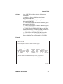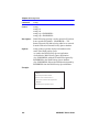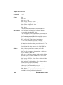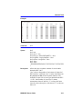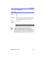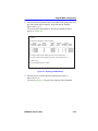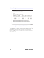
1
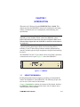
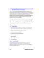
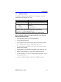
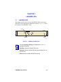
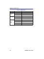
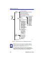
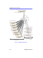
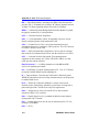
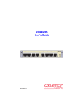
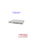
HSIM-W87 User’s Guide Title Page HSIM-W87 T3 TX LNK STS 9032689-02 RX CPU TELCO Only qualified personnel should perform installation procedures. NOTICE Cabletron Systems reserves the right to make changes in specifications and other information contained in this document without prior notice. The reader should in all cases consult Cabletron Systems to determine whether any such changes have been made. The hardware, firmware, or software described in this manual is subject to change without notice. IN NO EVENT SHALL CABLETRON SYSTEMS BE LIABLE FOR ANY INCIDENTAL, INDIRECT, SPECIAL, OR CONSEQUENTIAL DAMAGES WHATSOEVER (INCLUDING BUT NOT LIMITED TO LOST PROFITS) ARISING OUT OF OR RELATED TO THIS MANUAL OR THE INFORMATION CONTAINED IN IT, EVEN IF CABLETRON SYSTEMS HAS BEEN ADVISED OF, KNOWN, OR SHOULD HAVE KNOWN, THE POSSIBILITY OF SUCH DAMAGES. 1998 by Cabletron Systems, Inc., P.O. Box 5005, Rochester, NH 03866-5005 All Rights Reserved Printed in the United States of America Part Number: 9032689-02 September 1998 Cabletron Systems and LANVIEW are registered trademarks of Cabletron Systems, Inc. All other product names mentioned in this manual may be trademarks or registered trademarks of their respective companies. FCC NOTICE This device complies with Part 15 of the FCC rules. Operation is subject to the following two conditions: (1) this device may not cause harmful interference, and (2) this device must accept any interference received, including interference that may cause undesired operation. NOTE: This equipment has been tested and found to comply with the limits for a Class A digital device, pursuant to Part 15 of the FCC rules. These limits are designed to provide reasonable protection against harmful interference when the equipment is operated in a commercial environment. This equipment uses, generates, and can radiate radio frequency energy and if not installed in accordance with the operator’s manual, may cause harmful interference to radio communications. Operation of this equipment in a residential area is likely to cause interference in which case the user will be required to correct the interference at his own expense. WARNING: Changes or modifications made to this device which are not expressly approved by the party responsible for compliance could void the user’s authority to operate the equipment. HSIM-W87 User’s Guide i Notice INDUSTRY CANADA NOTICE This digital apparatus does not exceed the Class A limits for radio noise emissions from digital apparatus set out in the Radio Interference Regulations of the Canadian Department of Communications. Le présent appareil numérique n’émet pas de bruits radioélectriques dépassant les limites applicables aux appareils numériques de la class A prescrites dans le Règlement sur le brouillage radioélectrique édicté par le ministère des Communications du Canada. VCCI NOTICE This is a Class A product based on the standard of the Voluntary Control Council for Interference by Information Technology Equipment (VCCI). If this equipment is used in a domestic environment, radio disturbance may arise. When such trouble occurs, the user may be required to take corrective actions. CABLETRON SYSTEMS, INC. PROGRAM LICENSE AGREEMENT IMPORTANT: Before utilizing this product, carefully read this License Agreement. This document is an agreement between you, the end user, and Cabletron Systems, Inc. (“Cabletron”) that sets forth your rights and obligations with respect to the Cabletron software program (the “Program”) contained in this package. The Program may be contained in firmware, chips or other media. BY UTILIZING THE ENCLOSED PRODUCT, YOU ARE AGREEING TO BECOME BOUND BY THE TERMS OF THIS AGREEMENT, WHICH INCLUDES THE LICENSE AND THE LIMITATION OF WARRANTY AND DISCLAIMER OF LIABILITY. IF YOU DO NOT AGREE TO THE TERMS OF THIS AGREEMENT, PROMPTLY RETURN THE UNUSED PRODUCT TO THE PLACE OF PURCHASE FOR A FULL REFUND. ii HSIM-W87 User’s Guide Notice CABLETRON SOFTWARE PROGRAM LICENSE 1. LICENSE. You have the right to use only the one (1) copy of the Program provided in this package subject to the terms and conditions of this License Agreement. You may not copy, reproduce or transmit any part of the Program except as permitted by the Copyright Act of the United States or as authorized in writing by Cabletron. 2. OTHER RESTRICTIONS. You may not reverse engineer, decompile, or disassemble the Program. 3. APPLICABLE LAW. This License Agreement shall be interpreted and governed under the laws and in the state and federal courts of New Hampshire. You accept the personal jurisdiction and venue of the New Hampshire courts. EXCLUSION OF WARRANTY AND DISCLAIMER OF LIABILITY 1. EXCLUSION OF WARRANTY. Except as may be specifically provided by Cabletron in writing, Cabletron makes no warranty, expressed or implied, concerning the Program (including its documentation and media). CABLETRON DISCLAIMS ALL WARRANTIES, OTHER THAN THOSE SUPPLIED TO YOU BY CABLETRON IN WRITING, EITHER EXPRESSED OR IMPLIED, INCLUDING BUT NOT LIMITED TO IMPLIED WARRANTIES OF MERCHANTABILITY AND FITNESS FOR A PARTICULAR PURPOSE, WITH RESPECT TO THE PROGRAM, THE ACCOMPANYING WRITTEN MATERIALS, AND ANY ACCOMPANYING HARDWARE. 2. NO LIABILITY FOR CONSEQUENTIAL DAMAGES. IN NO EVENT SHALL CABLETRON OR ITS SUPPLIERS BE LIABLE FOR ANY DAMAGES WHATSOEVER (INCLUDING, WITHOUT LIMITATION, DAMAGES FOR LOSS OF BUSINESS, PROFITS, BUSINESS INTERRUPTION, LOSS OF BUSINESS INFORMATION, SPECIAL, INCIDENTAL, CONSEQUENTIAL, OR RELIANCE DAMAGES, OR OTHER LOSS) ARISING OUT OF THE USE OR INABILITY TO USE THIS CABLETRON PRODUCT, EVEN IF CABLETRON HAS BEEN ADVISED OF THE POSSIBILITY OF SUCH DAMAGES. BECAUSE SOME STATES DO NOT ALLOW THE EXCLUSION OR LIMITATION OF LIABILITY FOR CONSEQUENTIAL OR INCIDENTAL DAMAGES, OR ON THE DURATION OR LIMITATION OF IMPLIED WARRANTIES, IN SOME INSTANCES THE ABOVE LIMITATIONS AND EXCLUSIONS MAY NOT APPLY TO YOU. UNITED STATES GOVERNMENT RESTRICTED RIGHTS The enclosed product (a) was developed solely at private expense; (b) contains “restricted computer software” submitted with restricted rights in accordance with Section 52227-19 (a) through (d) of the Commercial Computer Software - Restricted Rights Clause and its successors, and (c) in all respects is proprietary data belonging to Cabletron and/or its suppliers. For Department of Defense units, the product is licensed with “Restricted Rights” as defined in the DoD Supplement to the Federal Acquisition Regulations, Section 52.227-7013 (c) (1) (ii) and its successors, and use, duplication, disclosure by the Government is subject to restrictions as set forth in subparagraph (c) (1) (ii) of the Rights in Technical Data and Computer Software clause at 252.227-7013. Cabletron Systems, Inc., 35 Industrial Way, Rochester, New Hampshire 03867-0505. HSIM-W87 User’s Guide iii Notice iv HSIM-W87 User’s Guide CONTENTS CHAPTER 1 INTRODUCTION 1.1 Using This Manual....................................................................... 1-1 1.2 Overview...................................................................................... 1-2 1.3 Data Flow in the HSIM-W87 ........................................................ 1-4 1.4 Features ...................................................................................... 1-4 1.4.1 Connectivity .................................................................... 1-4 1.4.2 HDLC .............................................................................. 1-5 1.4.3 Inverse Multiplexing (IMUX)............................................ 1-5 1.4.4 Priority Queuing .............................................................. 1-6 1.4.5 DS1 Alarm ...................................................................... 1-6 1.4.6 SNMP and MIB Support ................................................. 1-6 1.4.7 LANVIEW Diagnostic LEDs ............................................ 1-7 1.5 Document Conventions ............................................................... 1-7 1.6 Related Documentation ............................................................... 1-8 1.7 Getting Help................................................................................. 1-9 CHAPTER 2 INSTALLATION 2.1 Unpacking the HSIM-W87 ........................................................... 2-1 2.2 Installing the HSIM-W87.............................................................. 2-2 2.2.1 Installing the HSIM-W87 in an Interface Module ............ 2-2 2.2.2 Installing the HSIM-W87 in a Standalone Device ........... 2-5 2.3 Connecting the HSIM-W87 to the Network.................................. 2-6 2.4 HSIM-W87 Setup......................................................................... 2-6 CHAPTER 3 LANVIEW LEDs 3.1 LANVIEW LEDs........................................................................... 3-1 CHAPTER 4 MANAGEMENT 4.1 Local Management ...................................................................... 4-1 4.2 Network Tools.............................................................................. 4-3 4.2.1 Commands ..................................................................... 4-4 4.2.2 Built-in Commands ......................................................... 4-6 4.2.3 Special Commands....................................................... 4-13 4.3 Sample IMUX Configuration ...................................................... 4-14 HSIM-W87 User’s Guide v Contents CHAPTER 5 TROUBLESHOOTING 5.1 Troubleshooting the HSIM-W87..................................................5–1 5.1.1 Hardware Troubleshooting .............................................5–1 5.1.2 Investigating Software Configuration Problems .............5–3 5.1.3 Problems with the Firmware Image................................5–3 APPENDIX A SPECIFICATIONS A.1 Physical Properties ..................................................................... A-1 A.2 Environmental Requirements...................................................... A-1 A.3 Regulatory Compliance............................................................... A-2 APPENDIX B TYPICAL CONFIGURATION APPENDIX C WAN TERMS AND ACRONYMS vi HSIM-W87 User’s Guide CHAPTER 1 INTRODUCTION Welcome to the Cabletron Systems HSIM-W87 User’s Guide. This manual describes the HSIM-W87 and provides information concerning features, installation, the use of management, troubleshooting, and specifications. Important Notice Depending on the firmware version used in the HSIM-W87, some features described in this document may not be supported. Refer to the Release Notes shipped with the HSIM-W87 to determine which features are supported. A general working knowledge of Wide Area Networking (WAN), including T1 and T3 Networking, Ethernet and data communications networks, and their physical layer components is helpful when installing this device. The HSIM-W87 has one T3 port, which consists of two BNC connectors, a transmit and a receive port. Figure 1-1 shows the HSIM-W87. HSIM-W87 T3 TX RX LNK CPU STS TELCO Figure 1-1 1.1 HSIM-W87 USING THIS MANUAL Reading through this manual completely will help you understand the features and capabilities of the HSIM-W87. The following list provides an overview of each section of this manual: Chapter 1, Introduction, outlines the contents of this manual, describes the HSIM-W87 features and concludes with a web site address where related manuals can be obtained. HSIM-W87 User’s Guide 1-1 Chapter 1: Introduction Chapter 2, Installation, describes how to install an HSIM-W87 into an interface module or a standalone device (host platform). NOTE The term “host platform” is used to describe the interface module, or standalone device, into which the HSIM-W87 can be installed. Chapter 3, LANVIEW LEDs, describes how to use the HSIM-W87 LEDs to monitor the HSIM performance and status. Chapter 4, Management, describes the Network Tools needed for configuration for the HSIM-W87. Chapter 5, Troubleshooting, describes some of the common troubleshooting problems and possible solutions. Appendix A, Specifications, lists the operating specifications and regulatory compliance of the HSIM-W87. Appendix B, Typical Configuration, displays possible configurations for the HSIM-W87. Appendix C, WAN Terms and Acronyms, provides a glossary of some terms and acronyms used in this manual. 1.2 OVERVIEW The HSIM-W87 extends the functionality of certain Cabletron Systems platforms by providing an interface for Wide Area Network (WAN) DS3 services. The HSIM-W87 is a High Speed Interface Module (HSIM) used to provide WAN services using the SmartSwitch series of products as a platform. The HSIM-W87 has a physical DS3 interface, providing up to 28 separate logical DS1 connections. The 28 T1 circuits are all capable of acting either as a single 45 Mbps full duplex data circuit or as individual T1 circuits within a Layer 2 Inverse Multiplexing (IMUX) group. The typical configuration is a head-end WAN aggregation point for up to 28 T1s into a single WAN physical interface. The HSIM-W87 is able to uplink any combination of single T1s or multiple T1 IMUX groups to the backbone. 1-2 HSIM-W87 User’s Guide Overview The HSIM-W87 has its own i960 HD microprocessor used to process data packets, provide simple configuration, Inverse Multiplexer functionality, and statistics processing. The SmartSwitch host platform provides the required logical IP Host services. The HSIM-W87 is designed to be installed in any Cabletron Systems product that supports the High Speed Interface Module. The HSIM-W87 operates in two modes: • Switching • IMUX The first mode, switching, is the default mode. The HSIM-W87 forwards data packets received by the host platform out through the logical DS1 interfaces. It also forwards packets received in the DS1 interfaces to or through the host. The default and only layer 2 WAN protocol used with the HSIM-W87 is raw HDLC. NOTE The host platform may operate in 802.1D bridging, 802.1Q VLAN, or SecureFast mode. The second mode of operation is using Cabletron Systems Inverse Multiplexer (IMUX) functionality to aggregate multiple DS1 connections into single higher bandwidth WAN connections. In order to operate in this mode, the user will simply need to configure the appropriate IMUX groups containing the DS1 connections. Along with the built-in management features (Network Tools) described in Chapter 4, the HSIM-W87 can be managed using SNMP, and statistical data can be accessed via SNMP by referencing the interface group defined in RFC-1213. HSIM-W87 User’s Guide 1-3 Chapter 1: Introduction 1.3 DATA FLOW IN THE HSIM-W87 The T3 port receives the DS3 data through the coaxial interface. A T3 framer/Multiplexer strips off the T3 framing and provides 28 individual T1 data streams. The T1 data streams are then terminated by T1 framers, which provide an HDLC bit stream to the HDLC controller. The controller receives data packets from each of the bit streams and places them in a memory subsystem. An onboard CPU examines the packet and notifies the host of its arrival. Finally, a Cabletron proprietary ASIC transfers the data to the host platform. This process is followed in reverse when a packet is transmitted from the host platform out the T3 port. The host platform notifies the HSIM-W87 when a packet is coming and transfers the packet to the memory. The HDLC format is applied to the data; then the data is framed to a T1 format, and passed to the framer/ Multiplexer. The T1 data is multiplexed with other T1 streams and is transmitted out through the T3 interface. 1.4 FEATURES • Data Transfer Rates of 45 Mbps in full duplex, when running all 28 T1s carrying continuous data traffic of 128-byte packets or larger. • High-level Data Link Control (HDLC) protocol • T1 Inverse Multiplexing (IMUX) • WAN IP Priority Queuing functionality • DS1 Alarm Thresholds • SNMP support • DS1 and DS3 MIB Support • LANVIEW LEDs 1.4.1 Connectivity The HSIM-W87 module supports WAN technology using a DS3 interface, and supports 28 live full duplex T1 connections. The HSIM-W87 channelizes the T3 down to the DS1 level. The HSIM-W87 has an integrated M13 MUX. 1-4 HSIM-W87 User’s Guide Features The primary function of the HSIM-W87 is to provide LAN to WAN access. WAN physical connectivity will be supported through the use of a T3 interface with an unbalanced 75 ohm coaxial cable pair. LAN to WAN connectivity will be supported through HDLC and T1 Inverse Multiplexing (IMUX). The HSIM-W87 interoperates with those Cabletron Systems WAN products that support raw HDLC as the WAN protocol. This support is limited to the CyberSWITCH product line which supports HDLC: • CSX400 – Version 02.00.15 or higher • HSIM-W6 – Version 02.00.15 or higher • HSIM-W84 – Version 02.00.xx or higher • HSIM-W85 – Version 02.00.xx or higher 1.4.2 HDLC The High-level Data Link Control (HDLC) protocol is used in conjunction with the Inverse Multiplexing (IMUX) feature to conserve a user’s WAN bandwidth between two Cabletron Systems products, over a point-to-point connection. Cabletron Systems products such as the HSIM-W6, HSIM-W84, HSIM-W85, HSIM-W87, and CSX400 must be in use on both ends of the WAN link for these functions to work. The HDLC (RAW) protocol reduces the amount of overhead information that needs to be contained within each data packet to direct it to its destination. This decreased packet overhead provides the IMUX functions with more bandwidth to transfer user data. 1.4.3 Inverse Multiplexing (IMUX) Cabletron Systems Inverse Multiplexing (IMUX) feature provides enhanced throughput for users by doing the following: • The IMUX function evenly distributes a data packet stream from the LAN interface through multiple full T1 WAN interfaces on the HSIM-W87. • Data packet streams received by the WAN interfaces on the other end of the WAN links are then recombined, ordered, and transmitted to the LAN interface. HSIM-W87 User’s Guide 1-5 Chapter 1: Introduction • The IMUX function is configurable using the Network Tools command, imux, described in Chapter 4. NOTE 1.4.4 Cabletron Systems products that support Inverse Multiplexing (IMUX), such as the HSIM-W87, HSIM-W6, CSX400, HSIM-W84, and HSIM-W85, must exist on both ends of the WAN link for the IMUX function to work. All bridging and switching functions, such as 802.1D, SecureFast VLAN, and 802.1Q are able to run as normal on the host platform when using the IMUX function on the HSIM-W87. Priority Queuing WAN IP Priority Queuing is used to prioritize IP packets from a specified IP address. This prioritization ensures that certain packets get through the network, such as management packets which are necessary to the operation of the network, and routers that depend on protocols with tight timing, such as RIP, do not time out. The prioritized packets do not eliminate other traffic on the network, but are held in a special queue, so that they are not discarded during oversubscribed traffic peaks. Priority Queuing can be enabled in management, using Network Tools. Refer to the wanpq command in the Management chapter. 1.4.5 DS1 Alarm Using the DS1 Error Threshold Alarm Monitor provides a means of setting error thresholds and notifying the user of potential DS1 problems with SNMP trap events. The ds1alarm Monitor feature can be enabled in management, using Network Tools. Refer to the ds1alarm command in the Management chapter. 1.4.6 SNMP and MIB Support With the SNMP support, the MIBs supported by the HSIM-W87 include: • RFC 1406 – Definitions of Managed Objects for the DS1 and E1 Interface Types • RFC 1407 – Definitions of Managed Objects for the DS3/E3 Interface Type 1-6 HSIM-W87 User’s Guide Document Conventions • RFC 1213 (MIBII) support for the Interface Table • Cabletron Enterprise MIBs Refer to the Release Notes included with the host platform for a list of all MIBs supported by the HSIM-W87. For information about how to extract and compile individual MIBs, contact the Cabletron Systems Global Call Center (Section 1.7). 1.4.7 LANVIEW Diagnostic LEDs Cabletron Systems provides a visual diagnostic and monitoring system called LANVIEW. The HSIM-W87 LANVIEW LEDs help you quickly identify status of the device. Chapter 3 provides information on the HSIM-W87 LEDs. 1.5 DOCUMENT CONVENTIONS The following conventions are used throughout this document: NOTE ! Note symbol. Calls the reader’s attention to any item of information that may be of special importance. Caution symbol. Contains information essential to avoid damage to the equipment. CAUTION Electrical Hazard Warning symbol. Warns against an action that could result in personal injury or death due to an electrical hazard. TIP Tip symbol. Conveys helpful hints concerning procedures or actions. HSIM-W87 User’s Guide 1-7 Chapter 1: Introduction bold type Denotes either a user input or a highlighted screen selection. RETURN Indicates either the ENTER or RETURN key, depending on your keyboard. ESC Indicates the keyboard Escape key. SPACE bar Indicates the keyboard space bar key. BACKSPACE Indicates the keyboard backspace key. arrow keys Refers to the four keyboard arrow keys. [-] Indicates the keyboard – key. DEL Indicates the keyboard delete key. italic type Italic type emphasizes important information, indicates variables, and indicates complete document titles. n.nn A period in numerals signals the decimal point indicator. (e.g., 1.75 equals one and three fourths, or the Decimal Dotted Notation (DDN) for an IP address. x Indicates the generic use of a letter (e.g., xxx indicates any combination of three alphabetic characters). n Indicates the generic use of a number (e.g., 19nn indicates a four-digit number in which the last two digits are unknown). [] In the Local Management screens, the brackets indicate that a value may be entered or selected. In the format descriptions in the Network Tools section, required arguments are enclosed in []. <> In the format descriptions in the Network Tools section, optional arguments are enclosed in <>. 1.6 RELATED DOCUMENTATION The documentation for the host platform in which the HSIM-W87 is to be installed provides additional information about the setup of the HSIM-W87. The host documentation is not listed below, as there can be many different host platforms. This user’s guide references procedures in these documents, where appropriate, but does not repeat them. Documents can be obtained on the World Wide Web in Adobe Acrobat Portable Document Format (PDF) at the following site: http://www.cabletron.com/ 1-8 HSIM-W87 User’s Guide Getting Help 1.7 GETTING HELP For additional support related to this device or document, contact the Cabletron Systems Global Call Center: World Wide Web http://www.cabletron.com/ Phone (603) 332-9400 Internet mail [email protected] FTP ftp://ftp.cabletron.com/ anonymous your email address Login Password To send comments or suggestions concerning this document, contact the Cabletron Systems Technical Writing Department via the following email address: [email protected] Make sure to include the document Part Number in the email message. Before calling the Cabletron Systems Global Call Center, have the following information ready: • Your Cabletron Systems service contract number • A description of the failure • A description of any action(s) already taken to resolve the problem (e.g., changing mode switches, rebooting the unit, etc.) • The serial and revision numbers of all involved Cabletron Systems products in the network • A description of your network environment (layout, cable type, etc.) • Network load and frame size at the time of trouble (if known) • The device history (i.e., have you returned the device before, is this a recurring problem, etc.) • Any previous Return Material Authorization (RMA) numbers HSIM-W87 User’s Guide 1-9 Chapter 1: Introduction 1-10 HSIM-W87 User’s Guide CHAPTER 2 INSTALLATION To install the HSIM-W87 the following items are required: • Antistatic wrist strap (shipped with the HSIM-W87) • Phillips screwdriver NOTE 2.1 Before attempting to use the HSIM-W87 you should be familiar with the IEEE 802.3 Specifications, and T1 and T3 Networking. UNPACKING THE HSIM-W87 ! CAUTION The HSIM-W87 and the host platform are sensitive to static discharges. Use an antistatic strap and observe all static precautions during this procedure. Failure to do so could result in damage to the HSIM-W87 or host platform. Unpack the HSIM-W87 as follows: 1. Remove the HSIM-W87 from the shipping box. 2. Leave the module in its antistatic bag until you are ready to install it. 3. Attach the antistatic wrist strap (refer to the instructions on the antistatic wrist strap package for proper use). 4. After removing the module from its antistatic bag, visually inspect the device. If you notice any signs of damage, contact the Cabletron Systems Global Call Center immediately. Refer to Section 1.7 for instructions. Save the antistatic bag in the event the module must be reshipped or relocated. HSIM-W87 User’s Guide 2-1 Chapter 2: Installation 2.2 INSTALLING THE HSIM-W87 Only qualified personnel should install or service this unit. An HSIM-W87 can be installed in any Cabletron Systems device that supports HSIM technology (e.g., 2H252-25R, 2E42-27, 6E132-25). NOTE Refer to the release notes for the version of firmware running on the Cabletron Systems host platform to ensure that the HSIM-W87 is supported. The following subsections provide instructions for installing an HSIM-W87 in a host platform. Refer to the specific interface module or standalone device document for exact HSIM slot and connector locations. 2.2.1 Installing the HSIM-W87 in an Interface Module To install an HSIM-W87 in an interface module that supports HSIM technology, perform the following steps. 1. Note the ports of the interface module that have cables attached to them. Write down the ports and label the cables to make it easier to reattach the network properly after the installation. Then disconnect those cables from the ports. 2. Attach the antistatic wrist strap (refer to the instructions outlined on the antistatic wrist strap package). 3. If the interface module is installed in a chassis, unlock the top and bottom plastic locking tabs of the module faceplate. 4. Remove the module from the chassis, and place it down flat with the internal components facing up. 5. Remove and save the two faceplate mounting screws securing the HSIM coverplate and remove the coverplate. See Figure 2-1. 2-2 HSIM-W87 User’s Guide Installing the HSIM-W87 HSIM Coverplate Faceplate Mounting Screws Host Platform 2555_03 Figure 2-1 Removing the HSIM Coverplate 6. Refer to Figure 2-2 and place the HSIM-W87 behind the module faceplate. HSIM-W87 User’s Guide 2-3 Chapter 2: Installation Standoff Screws Connector Connector Cutaway view of connector HSIM-W87 LN K TX ST T3 S RX TE LC O HS IM -W 87 CP U HSIM Pins SP Standoffs Faceplate Mounting Screws Interface Module or Device mounting Figure 2-2 Installing the HSIM-W87 7. Align the connector on the HSIM-W87 with the pins on the module. ! CAUTION Ensure that the HSIM-W87 connector aligns with the module connector pins to prevent bending the pins. This can damage both the HSIM-W87 and the module. 8. Press down firmly on the connector area of the HSIM-W87 until the connector slides all the way onto the pins. Ensure that the standoffs on the interface module align with the standoff screw holes on the HSIM-W87. 2-4 HSIM-W87 User’s Guide Installing the HSIM-W87 9. Secure the HSIM-W87 to the module faceplate using the mounting screws saved in Step 5. 10. Secure the HSIM-W87 to the module standoffs using the standoff screws included in the HSIM-W87 shipping materials. 11. Reinstall the interface module in the chassis. 12. Reattach the network cabling to the interface module. 2.2.2 Installing the HSIM-W87 in a Standalone Device To install an HSIM-W87 into a standalone device (e.g., 2H252-25R) perform the following steps: 1. Power down the device and remove the power cord. 2. Note the ports that have cables attached to them. Write down the ports and label the cables to make it easier to reattach the network properly after the installation. Then disconnect those cables from the ports. To install the HSIM-W87 in a standalone device the device must first be powered down. Ensure that you remove the power cord and ONLY the screws required to remove the chassis cover. 3. Attach the antistatic wrist strap (refer to the instructions outlined on the antistatic wrist strap package). 4. Remove the standalone device chassis cover (refer to your specific standalone device documentation for instructions on removing the chassis cover). 5. Refer back to Figure 2-1 and remove the two faceplate mounting screws and the HSIM coverplate. Save the screws. 6. Refer back to Figure 2-2 and place the HSIM-W87 behind the standalone device faceplate. 7. Align the HSIM connector of the HSIM-W87 with the pins on the standalone device. HSIM-W87 User’s Guide 2-5 Chapter 2: Installation ! CAUTION Ensure that the HSIM-W87 connector aligns with the device connector pins to prevent bending the pins. This can damage both the HSIM-W87 and the device. 8. Press down firmly on the HSIM-W87 until the connector slides all the way onto the HSIM pins. Ensure that the standoffs on the standalone device align with the standoff screw holes on the HSIM-W87. 9. Secure the HSIM-W87 to the module faceplate using the mounting screws saved in Step 5. 10. Secure the HSIM-W87 to the module standoffs using the standoff screws included in the HSIM-W87 shipping materials. Ensure that the chassis cover is in place before reconnecting the power cord. 11. Replace the chassis cover on the standalone device, reconnect the power cord, and reconnect the standalone device to the network. 2.3 CONNECTING THE HSIM-W87 TO THE NETWORK The HSIM-W87 is connected to the carrier’s DS3 service using coaxial cable. The 75 Ohm unbalanced coaxial cable may be run a maximum of 450 feet. For typical configurations for the HSIM-W87, see Appendix B. 2.4 HSIM-W87 SETUP See Chapter 3 for information on the LEDs, Chapter 4 on how to set up the HSIM-W87 in management, and Chapter 5 for Troubleshooting. 2-6 HSIM-W87 User’s Guide CHAPTER 3 LANVIEW LEDs 3.1 LANVIEW LEDS This chapter describes how to use the LANVIEW LEDs to monitor the HSIM-W87 status and diagnose HSIM-W87 problems. Figure 3-1 shows the location of the HSIM-W87 LEDs. Link HSIM-W87 T3 TX RX LNK STS CPU TELCO Status CPU w87_LEDs Figure 3-1 NOTE HSIM-W87 LANVIEW LEDs The terms flashing, blinking, and solid used in Table 3-1 indicate the following: Flashing indicates an irregular LED pulse. Blinking indicates a steady LED pulse (approximately 50% on and 50% off). Solid indicates a steady LED light. No pulsing. HSIM-W87 User’s Guide 3-1 Chapter 3: LANVIEW LEDs Table 3-1 LED Processor (CPU) Link (LNK) Status (STS) 3-2 HSIM-W87 LEDs Color Definition Off Power Off Green (solid) Fully operational Red (solid) System in reset mode (temporary) Red No Link or Receive signal Amber Traffic on at least one port Green Link but sync may not be present Off Normal Red Red Alarm Green (blinking) Receiving Blue Alarm Amber Yellow Alarm Amber (blinking) Port is performing diagnostics HSIM-W87 User’s Guide CHAPTER 4 MANAGEMENT This chapter describes Local Management and the Network Tools utility. Local Management allows access to statistics screens that apply to the HSIM-W87 through the host platform. Network Tools allows access to a command set from which you can configure and manage the HSIM-W87. This chapter provides the following information: • Overview of Local Managment, Section 4.1 • Network Tools used with the HSIM-W87, Section 4.2 • Sample IMUX configuration, Section 4.3 4.1 LOCAL MANAGEMENT NOTE Access to Local Management screens and Network Tools is obtained by using Local Management on the host platform. Refer to the host platform user’s guide to establish a Local Management connection, and for information on the screens. Make sure that the following requirements have been met before accessing the HSIM-W87 through Local Management: • The HSIM-W87 is properly installed in the host platform. • A management terminal is properly configured and connected, either locally or using Telnet, to the host platform in which the HSIM-W87 resides. Refer to the host platform document for further information. In order to view the HSIM-W87 statistics screens, you must navigate through a series of Local Management screens via the host platform. Figure 4-1 shows a typical hierarchy of screens that you would navigate through in order to reach the HSIM-W87 screens. The lines shown in boldface indicate a typical path used to access the HSIM-W87 statistics screens. HSIM-W87 User’s Guide 4-1 Chapter 4: Management Device Configuration Menu General Configuration SNMP Community Names Configuration SNMP Traps Configuration System Resources Information Flash Download Configuration Password Port Configuration Menu 802.1 Configuration Menu Device Menu Switch Configuration 802.1Q VLAN Configuration Menu Device/VLAN Configuration Port Assignment Configuration Port Filtering Configuration VLAN Forwarding Configuration Ethernet Interface Configuration HSIM/VHSIM Configuration Port Redirect Configuration Flow Control Configuration SmartTrunk Configuration Broadcast Suppression Configuration 802.1p Priority Configuration Menu Port Priority Configuration Advanced Port Priority Configuration Device Statistics Menu Switch Statistics Interface Statistics RMON Statistics HSIM/VHSIM Statistics Network Tools Figure 4-1 NOTE 2555hier Typical Hierarchy of Local Management Screens Different versions of the firmware may display a different hierarchy. Check the host platform manual if the hierarchy displayed does not match the one in Figure 4-1. The HSIM/VHSIM Statistics menu option underneath the Device Statistics Menu applies to the non-Ethernet HSIMs or VHSIMs such as ATM or FDDI, but not the HSIM-W87. 4-2 HSIM-W87 User’s Guide Network Tools Important Notice The HSIM-W87 statistics that are accessed using the Switch and Interface Statistics screens are not explained in this manual. Refer to the applicable host platform manual for details. “T3 Interface” and “T1 Interface” will be displayed as the name of the HSIM-W87 interface in the statistics screens. 4.2 NETWORK TOOLS The Network Tools utility allows management of objects in the HSIM-W87 Management Information Bases (MIBs). MIBs are databases of objects used for managing the device and configuring the HSIM-W87. The commands within the MIB Navigator allow the user to view and modify a device’s objects. The host platform contains either the Network Tools utility, or the MIB Navigator utility. They are essentially the same tool, with some minor differences depending on the platform. They will both be referred to as Network Tools in this document, and there is no difference in their use for the purpose of this document. Using Network Tools may be a more convenient method for a user to configure the HSIM-W87 than using the MIBs in some circumstances. Full functionality is still available by using the MIBs. The host platform has a set of functions for Network Tools that are used on that platform. The following additions to the Network Tools utility from the WAN perspective are specific to the HSIM-W87, and can only be used when a HSIM-W87 is installed in the platform. • imux – support for configuration and monitoring of the Inverse Multiplexer (ctwan-multi-imux-mib.txt, Revision 1.00.00) • ds1alarm – support for ds1 alarm monitoring (ctremote-mib.txt, Revision 1.00.02, Ds1Alarms branch) • wanpq – support for Wan IP Priority Queuing (ctremote-mib.txt, Revision 1.00.02, ctIPPQFilters branch) • dsx1 – support for RFC 1406 statistics and configuration • dsx3 – support for RFC 1407 statistics and configuration Only the above commands, that are particular to the HSIM-W87, will be described in the following sections. The host platform’s manual describes the other commands that are not particular to the HSIM-W87. Refer to the host platform manual for information on the other commands. HSIM-W87 User’s Guide 4-3 Chapter 4: Management 4.2.1 Commands The Network Tools function resides on the host platform and allows the user to access and manage network devices. Figure 4-2 shows the Network Tools Help screen. Screens may be slightly different depending on the host platform and the version of firmware. To access the Network Tools screen, access Local Management, then use the arrow keys to navigate to and highlight the NETWORK TOOLS menu item in the appropriate menu screen and press ENTER. The Network Tools Help screen displays. Refer to the host platform manual for details on accessing Local Management. Type help at the prompt to list all the commands that are available for the device in the current operational mode. If help is needed with a specific command, type help and the <command>. Use lower case characters when entering commands in Network Tools. Uppercase characters may be specified for some of the options. A command used incorrectly (wrong syntax or case) will prompt a display of the correct usage. TIP -> help Commands Available to the User: Built in Commands: bridge arp netstat show ping traceroute soft_reset imux dsx1 ds1alarm dsx3 telnet defroute reset link_trap wanpq SPECIAL: done, quit, or exit - Exit from the Network Tools. For help with a specific command, type 'help <command>'. -> 090829 Figure 4-2 4-4 Network Tools Help Screen HSIM-W87 User’s Guide Network Tools The Network Tools functions are performed using a series of commands. Entering commands in Network Tools involves typing the command at the Network Tools prompt, adding any required parameters, and pressing ENTER to execute the command. There are two categories of commands in the command set. • Built-in Commands – Allow the user to access and manage network devices. The commands for the HSIM-W87 are imux, ds1alarm, wanpq, dsx1, and dsx3. The other commands listed in Figure 4-2 are described in the host platform manual. • Special Commands – Allow the user to exit from Network Tools. The commands are done, exit, and quit. All three commands perform the exact same function. NOTE The conventions used in describing the commands in Network Tools are as follows: Arguments enclosed by [ ] are required. Arguments enclosed by < > are optional. In the following command examples, the information entered by the user is shown in bold Helvetica font. To abort the output or interrupt a process, press the CONTROL key and c key simultaneously, designated as ^C here. The commands are presented in the following format: command: Syntax: Shows the required command format. It indicates where arguments, if any, must be specified. Description: Briefly describes the command and its uses. Options: Lists any additional fields in the appropriate format that may be added to the command. Example: Shows an example of how to use the command. HSIM-W87 User’s Guide 4-5 Chapter 4: Management 4.2.2 Built-in Commands The built-in commands listed in this section activate configuration and viewing functions on the HSIM-W87. imux: NOTE Cabletron Systems products that support Inverse Multiplexing (IMUX), such as the HSIM-W87, HSIM-W6, CSX400, and HSIM-W84, must exist on both ends of the WAN link for the IMUX function to work. All bridging and switching functions, such as 802.1D, SecureFast VLAN, and 802.1Q are able to run as normal on the host platform when using the IMUX function on the HSIM-W87. Syntax: imux <IMUXID> imux <IMUXID> -[ea | da] imux <IMUXID> -[eg | dg] <GROUPID> imux <IMUXID> -[ac | dc] <GROUPID> <INTERFACENUM> Description: imux is used to combine multiple WAN channels into logical inverse multiplexing (IMUX)groups. Once the IMUX is configured, data will be evenly distributed over all of the logical channels configured. <IMUXID> - A unique value identifying an element in a sequence of Inverse Multiplexer Applications which belong to an IP host. <GROUPID> - A unique value identifying an element in a sequence of groups which belong to a WAN Inverse Multiplexer Application. <INTERFACENUM> - The MIB II ifIndex value used to represent a WAN channel that has an appropriate datalink protocol associated with it. 4-6 HSIM-W87 User’s Guide Network Tools Options: imux <IMUXID> (with no options) displays status information. -ea enables the Inverse Multiplexer Application designated by IMUXID. -da disables the Inverse Multiplexer Application designated by IMUXID. -eg <GROUPID> enables the Inverse Multiplexer group designated by GROUPID. -dg <GROUPID> disables the Inverse Multiplexer group designated by GROUPID. -ac <GROUPID> <INTERFACENUM> Adds the WAN channel designated by INTERFACENUM to the Inverse Multiplexer group designated by GROUPID. -dc <GROUPID> <INTERFACENUM> Deletes the WAN channel designated by INTERFACENUM from the Inverse Multiplexer group designated by GROUPID. Example: -> imux 1 -ac 1 29 # Inverse Multiplexer channel with ifIndex 29 added to group 1 -> imux 1 # # WAN Inverse Multiplexer 1 Status: Disabled # # Inverse WAN Available Xmit Byte Inverse # Multiplexer Group Physical BW Count Multiplexer Channel # ID Admin Status Number (bits/sec) (bytes) ID IfIndex Status #------------------------------------------------------------------------------------------------------------# 1 Disabled 22 1536000 0 1 29 INACTIVE # # # Number of WAN Inverse Multiplexer Groups currently programmed : 1 # # Number of WAN Inverse Multiplexer Channels currently programmed : 1 imuxsetup1 HSIM-W87 User’s Guide 4-7 Chapter 4: Management command: wanpq Syntax: wanpq wanpq -ea wanpq -da wanpq -aip <IPADDRESS> wanpq -dip <IPADDRESS> Description: WAN IP Priority Queuing is used to prioritize IP packets from a specified IP address. <IPADDRESS> - The Internet Protocol (IP) address being added to or removed from the Wide Area Network Priority Queue database. Options: wanpq (with no options) displays information on the status of the WAN priority queue. -ea enables the WAN Priority Queue Application. -da disables the WAN Priority Queue Application. -aip <IPADDRESS> Adds the IP address designated by IPADDRESS to the WAN Priority Queue database. -dip <IPADDRESS> Deletes the IP address designated by IPADDRESS from the WAN Priority Queue database. Example: -> wanpq # #WAN Priority Queue Status: Disabled # #Maximum number of address entries: 16 # #Current number of address entries programmed: 0 # -> wanpq -ea # # WAN Priority Queue Application enabled. -> 2689_1 4-8 HSIM-W87 User’s Guide Network Tools command: ds1alarm Syntax: ds1alarm ds1alarm -[ea | da] <WANID> ds1alarm -[et | dt] <WANID> ds1alarm -sec <WANID> <VALUE> ds1alarm -sei <WANID> <VALUE> ds1alarm -mr <WANID> Description: The ds1alarm function allows the user to set error thresholds in order to set traps and monitor the operation and recovery of a device. <WANID> This option is either ALL to apply command to all DS1 circuits, or the specific WAN physical identifier associated with the DS1 circuit. Options: ds1alarm (with no options) displays information on the error thresholds. -ea enables the WAN DS1 Alarms Admin. -da disables the WAN DS1 Alarms Admin. -et enables the WAN DS1 Alarms Traps Feature. -dt disables the WAN DS1 Alarms Traps Feature. -sec sets the Errored Seconds Threshold Count to VALUE. -sei sets the Errored Seconds Threshold Interval to VALUE. -mr manually recovers a DS1 link that has exceeded a threshold. Example: -> ds1alarm #-------------------------------------------------------------------------------------------------------------------------# DS1 Alarm Thresholds #-------------------------------------------------------------------------------------------------------------------------# HSIM DS1 DS1 Admin Trap ES ES # ID Index ID Status Admin Count Interval # (minutes) #-------------------------------------------------------------------------------------------------------------------------# 1 1 29 Disabled Enabled 100 6 # 1 2 30 Disabled Enabled 100 6 # 1 3 31 Disabled Enabled 100 6 # 1 4 32 Disabled Enabled 100 6 # 1 5 33 Disabled Enabled 100 6 # 1 6 34 Disabled Enabled 100 6 # 1 7 35 Disabled Enabled 100 6 ----More---2689_2 HSIM-W87 User’s Guide 4-9 Chapter 4: Management command: dsx1 Syntax: dsx1 dsx1 near dsx1 near <1..96> dsx1 linetype <ESF|D4> <line> dsx1 loopback <no|payload|line> <line> dsx1 txclksrc <loop|local> <line> dsx1 <line> dsx1 <line> <ES|SES|SEFS|UAS|CSS|PCV|LES|BES|DM|LCV> Description: This command allows the user to read the contents of several tables defined in RFC 1406. “line”, as an option, refers to the number of an instance of a physical T1 interface. A different “line” is in the choice between no, payload, and line for the loopback function. The acronyms in caps refer to error types defined in the RFC. Refer to RFC1406 for more information. <1..96> is the number of a previous 15 minute measurement interval in the table. Interval “1” is always the latest interval to have taken place, with interval “2” as the next latest, etc. Near indicates the device on your side of the WAN line. Options: dsx1 (with no options) lists a summary of the DS1 configuration. dsx1 near lists a summary of the statistics for the device on your side of the WAN line. dsx1 near <1..96> lists a summary of the statistics for the device on your side of the WAN line for a specific time interval. dsx1 linetype <ESF|D4> <line> allows a choice of either ESF or D4 linetype (framing). dsx1 loopback <no|payload|line> <line> allows a choice of either no, payload, or line loopback. dsx1 txclksrc <loop|local> <line> allows a choice of either loop or local transmit clock source. dsx1 <line> displays the setup for the line specified. dsx1 <line> <ES|SES|SEFS|UAS|CSS|PCV|LES|BES|DM|LCV> allows the choice of performance parameters. 4-10 HSIM-W87 User’s Guide Network Tools Example: -> dsx1 DS1 1406 Configuration: LIne Time Intvl Type Coding LoopCfg Status TxClk FDL 29 30 31 32 33 34 35 36 37 38 39 40 41 42 43 44 45 504 504 504 504 504 504 504 504 504 504 505 505 505 505 505 505 505 1 1 1 1 1 1 1 1 1 1 1 1 1 1 1 1 1 ESF ESF ESF ESF ESF ESF ESF ESF ESF ESF ESF ESF ESF ESF ESF ESF ESF B8ZS B8ZS B8ZS B8ZS B8ZS B8ZS B8ZS B8ZS B8ZS B8ZS B8ZS B8ZS B8ZS B8ZS B8ZS B8ZS B8ZS NoLoop NoLoop NoLoop NoLoop NoLoop NoLoop NoLoop NoLoop NoLoop NoLoop NoLoop NoLoop NoLoop NoLoop NoLoop NoLoop NoLoop OtherFailure OtherFailure OtherFailure OtherFailure OtherFailure OtherFailure OtherFailure OtherFailure OtherFailure OtherFailure OtherFailure OtherFailure OtherFailure OtherFailure OtherFailure OtherFailure OtherFailure loop loop loop loop loop loop loop loop loop loop loop loop loop loop loop loop loop Fdlnone Fdlnone Fdlnone Fdlnone Fdlnone Fdlnone Fdlnone Fdlnone Fdlnone Fdlnone Fdlnone Fdlnone Fdlnone Fdlnone Fdlnone Fdlnone Fdlnone ----More---2689_2 command: dsx3 Syntax: dsx3 dsx3 near dsx3 near <1..96> dsx3 linetype <M23|CBITPARITY> <line> dsx3 loopback <no|payload|line> <line> dsx3 txclksrc <loop|local> <line> dsx3 <line> dsx3 <line> <PES|PSES|SEFS|UAS|LCV|PCV|LES|CCV|CES|CSES > Description: Allows the user to read the contents of several tables defined in RFC 1407. “line” refers to the number of an instance of a physical DS3 interface. A different “line” is in the choice between no, payload, and line for the loopback function. The acronyms in caps refer to error types defined in the RFC. <1..96> is the number of a previous 15 minute measurement interval. Interval “1” is always the latest interval to have taken place, with interval “2” as the next latest, etc. HSIM-W87 User’s Guide 4-11 Chapter 4: Management Options: dsx3 (with no options) lists the dsx3 configuration. dsx3 near lists a summary of the near end setup statistics. dsx3 near <1..96> lists a summary of the near end setup statistics for the interval specified. dsx3 linetype <M23|CBITPARITY> <line> allows a choice between the types of parities, M23 and Cbit for the linetype of the line specified. dsx3 loopback <no|payload|line> <line> allows a choice of loopback between the listed choices for the line specified. dsx3 txclksrc <loop|local> <line> allows a choice of either loop or local transmit clock source. dsx3 <line> displays a summary of the line specified. dsx3 <line> <PES|PSES|SEFS|UAS|LCV|PCV|LES|CCV|CES|CSES > allows a choice of performance parameters for the line specified, accumulated in 15 minute intervals. Example: -> dsx3 Line 27 -> Time 680 Intvl 1 Type CBPar Coding B3ZS LoopCfg NoLoop Status TxClk LossOfSignallocal 2689_5 4-12 HSIM-W87 User’s Guide Network Tools 4.2.3 Special Commands done, quit, exit: Syntax: done quit exit Description: The done, exit, or quit command enables the user to exit from Network Tools and return to the Main Menu screen. All three commands perform the same function. Options: Not Applicable Example: -> done 051472 TIP To find the MIB II interface indexes assigned to the ds1 channels used in the IMUX group, utilize the dsx1 and ds1alarm commands. With the dsx1 command, the interface numbers are in the column under “line” in the display. When the ds1alarm command is used, the interface numbers, as well as the HSIM ID and the ds1 index, can be seen for verification. HSIM-W87 User’s Guide 4-13 Chapter 4: Management 4.3 SAMPLE IMUX CONFIGURATION The following is a sample of a common configuration. To perform an IMUX configuration for the setup shown in Figure B-1, in Appendix B, follow these steps: 1. To add channels to an IMUX group: Enter: imux 1 -ac 1 29 (this adds interface 29 to the group id 1 in the imux id 1) To display the setup so far: Enter: imux 1 Figure 4-3 shows the imux setup for group id 1 so far: -> imux 1 -ac 1 29 # Inverse Multiplexer channel with ifIndex 29 added to group 1 -> imux 1 # # WAN Inverse Multiplexer 1 Status: Disabled # # Inverse WAN Available Xmit Byte Inverse # Multiplexer Group Physical BW Count Multiplexer Channel # ID Admin Status Number (bits/sec) (bytes) ID IfIndex Status #------------------------------------------------------------------------------------------------------------# 1 Disabled 22 1536000 0 1 29 INACTIVE # # # Number of WAN Inverse Multiplexer Groups currently programmed : 1 # # Number of WAN Inverse Multiplexer Channels currently programmed : 1 imuxsetup1 Figure 4-3 4-14 Adding Channels to an IMUX Group HSIM-W87 User’s Guide Sample IMUX Configuration 2. After all the desired channels have been added to the group (four were put in the group in this example), the group must be enabled: Enter: imux 1 -eg 1 The screen shows the response to the imux command to enable group 1 in Figure 4-4. -> imux 1 # # WAN Inverse Multiplexer 1 Status: Disabled # # Inverse WAN Available Xmit Byte Inverse # Multiplexer Group Physical BW Count Multiplexer Channel # ID Admin Status Number (bits/sec) (bytes) ID IfIndex Status #------------------------------------------------------------------------------------------------------------# 1 Disabled 21 1536000 0 1 28 INACTIVE # 1 Disabled 22 1536000 0 2 29 INACTIVE # 1 Disabled 23 1536000 0 3 30 INACTIVE # 1 Disabled 24 1536000 0 4 31 INACTIVE # # # Number of WAN Inverse Multiplexer Groups currently programmed : 1 # # Number of WAN Inverse Multiplexer Channels currently programmed : 4 -> imux 1 -eg 1 # Inverse Multiplexer group 1 enabled. imuxsetup2 Figure 4-4 Enabling the IMUX Group 3. The next step is to enable the imux application for imux 1: Enter: imux 1 -ea The screen in Figure 4-5 displays the response to the command. HSIM-W87 User’s Guide 4-15 Chapter 4: Management ->imux 1 -ea # Inverse Multiplexer Application 1 enabled. -> imux 1 # WAN Inverse Multiplexer 1 Status: Enabled # # Inverse WAN Available Xmit Byte Inverse # Multiplexer Group Physical BW Count Multiplexer Channel # ID Admin Status Number (bits/sec) (bytes) ID IfIndex Status #------------------------------------------------------------------------------------------------------------# 1 Enabled 21 1536000 0 1 28 INACTIVE # 1 Enabled 22 1536000 0 2 29 INACTIVE # 1 Enabled 23 1536000 0 3 30 INACTIVE # 1 Enabled 24 1536000 0 4 31 INACTIVE # # # Number of WAN Inverse Multiplexer Groups currently programmed : 1 # # Number of WAN Inverse Multiplexer Channels currently programmed : 4 -> imuxsetup3 Figure 4-5 Enabling the IMUX Application This configuration is complete. More groups can be added as needed. The commands dsx1 and/or ds1alarm can be used to verify the interface numbers configured. Done, exit, or quit may be used after verification to leave Network Tools. 4-16 HSIM-W87 User’s Guide CHAPTER 5 TROUBLESHOOTING 5.1 TROUBLESHOOTING THE HSIM-W87 Problems in setup can occur in hardware, software, or firmware setups. The following sections detail some of the problems encountered and the possible solution. If a problem persists, contact the Cabletron Systems Global Call Center. Refer to Section 1.7. 5.1.1 Hardware Troubleshooting No LEDs on • Check the host platform to see if it is powered up. • Check that the HSIM-W87 has been connected correctly, that the connectors have no bent pins. Link (LNK) LED is OFF The WAN interface is not configured for operation. Power is off or the HSIM-W87 is not connected properly. Link (LNK) LED is RED — The WAN interface is configured, but there is no signal indicating that a valid connection is present on the WAN interface. • Check that the device at the other end of the segment is powered up. • Use management to make sure that both WAN interfaces, local and remote, are configured correctly. • Check to ensure that the correct cable is being used. • Check to ensure that the cable has continuity and is installed correctly. The cabling between the HSIM-W87 and the M13 should be checked, and the cabling between the M13 and the devices at the far end should also be checked. • Check with the WAN Service Provider to ensure that the circuit has been configured by them and is active. HSIM-W87 User’s Guide 5-1 Chapter 5: Troubleshooting NOTE It may be necessary to provide proof of proper configuration of your WAN connection. Service Providers typically require proof that the customer’s equipment is configured correctly before checking their own configuration. Status (STS) LED is OFF The port is operating normally. If it is not, and this LED is OFF, the port may be disabled. Use management to make sure that the WAN interface on the HSIM-W87 is configured correctly. Status (STS) LED is RED A RED alarm indicates that the WAN connection is not receiving proper framing or has lost framing from the remote device. • Verify the framing, zero suppression, and T3 clock source. • Verify the use of proper cabling on the WAN connection. Status (STS) LED is AMBER The device is in Yellow alarm mode. A Yellow alarm indicates that the HSIM-W87 is receiving proper framing from the Telco, but the Telco is not receiving proper framing. • Check for faulty or incorrect cabling between the Telco and the HSIM-W87. • Request that the Telco verify the configuration and operation of the circuit. Status (STS) LED is AMBER (blinking) Device is in test mode. • The HSIM-W87 is running its Power-up Diagnostic Tests. • Loopback Testing is underway on a WAN circuit. Loopback testing can be initiated by the Telco. 5-2 HSIM-W87 User’s Guide Troubleshooting the HSIM-W87 5.1.2 Investigating Software Configuration Problems Software problems usually occur when your software configuration contains incomplete or incorrect information. Device not forwarding packets • Ensure that the proper DS1 transmit clock source is configured using the dsx1 command in Network Tools. NOTE When connecting two ds1 devices, one must be tx clock master (local timing) and the other must be slave (loop timing). • Check the DS1 line type. The default is ESF but some devices may be configured for D4. Ensure that the local and remote DS1 devices are configured with the same line (Framing) type. • Ensure that the DS1 loopback is not configured (default is none) using the dsx1 command. 5.1.3 Problems with the Firmware Image The firmware image for the HSIM-W87 is supported on the host platform, therefore, if there is a problem with the firmware image for the HSIM-W87, the image for the platform must be downloaded. Refer to the host platform user’s guide for information on this procedure. HSIM-W87 User’s Guide 5-3 Chapter 5: Troubleshooting 5-4 HSIM-W87 User’s Guide APPENDIX A SPECIFICATIONS This chapter lists the specifications and regulatory requirements for the HSIM-W87. Cabletron Systems reserves the right to change these specifications at any time without notice. A.1 PHYSICAL PROPERTIES WAN Interface DS3 T3 port Physical Interface BNC connectors Cable Type 75 Ohm unbalanced Coaxial cable Maximum Link Distance 450 feet (137 m) T3 Cable Part Number 9310039-10ft 9310039-xx Microprocessor i960HD66 Power Supply +5V supplied by host device Power Consumption 18.75 Watts maximum Memory 8 MB of DRAM Local memory 4 MB of DRAM Shared memory Dimensions 4.8H x 20.6W x 28.7D (cm) 1.9H x 8.1W x 11.3D (in) Weight 0.45 kg (1.0 lb) MTBF (Predicted) 200,000 hours A.2 ENVIRONMENTAL REQUIREMENTS Operating Temperature 5°C to 40°C (41°F to 104°F) Storage Temperature -30°C to 90°C (-22°F to 194°F) Operating Relative Humidity 5% to 95% (non-condensing) HSIM-W87 User’s Guide A-1 Appendix A: Specifications A.3 REGULATORY COMPLIANCE This equipment meets the following safety and electromagnetic compatibility (EMC) requirements: Safety UL 1950 and CSA C22.2 No. 950 Electromagnetic Compatibility (EMC) FCC Part 15, EN 55022, CSA C108.8, EN 50082-1, VCCI V-3, 89/336/EEC, and AS/NZS 3548 A-2 HSIM-W87 User’s Guide APPENDIX B TYPICAL CONFIGURATION Typical configuration is a head-end WAN aggregation point for up to 28 T1s into a single WAN physical interface. The HSIM-W87 can uplink any combination of single T1s or multiple T1 IMUX groups to the backbone. The HSIM-W87 has an internal M13, and the Telco side M13, as shown in Figure B-1, is supplied for CPE aggregation. The HSIM-W84 in the diagram can be any device that is compatible with the HSIM-W87, which runs HDLC WAN protocol. NOTE In Figure B-1, the 2E42-27 is used as an example platform. It could be any platform into which the HSIM-W87 can be installed. HSIM-W87 User’s Guide B-1 Appendix B: Typical Configuration 2E42-27 with an HSIM-W87 T3 Telco Cloud M13 28 T1 Lines 2E42-27s with HSIM-W84s CSX400 CSX400 CSX400 CSX400 T1 Configuration configW87 IMUX Configuration Figure B-1 B-2 HSIM-W87 IMUX Operational HSIM-W87 User’s Guide APPENDIX C WAN TERMS AND ACRONYMS This appendix provides definitions for WAN terms and acronyms. AIS — Alarm Indication Signal, The DS3 AIS is framed with “stuck stuffing”. This implies that it has a valid M-subframe alignment bits, M-frame alignment bits, and P bits. The information bits are set to a 1010... sequence, starting with a one (1) after each M-subframe alignment bit., M-frame alignment bit, X bit, P bit, and C bit. The C bits are all set to zero giving what is called “stuck stuffing”. The X bits are set to one. The DS3 AIS defect is declared after DS3 AIS is present in contiguous M-frames for a time equal to or greater than T, where 0.2 ms<=T<=100 ms. The DS3 AIS defect is terminated after AIS is absent in contiguous M-frames for a time equal to or greater than T. AMI — Alternate Mark Inversion, line coding used with both E-1 and T1. A digital 1 is encoded as a “mark” (pulse) and a 0 is encoded as a “space.” The marks alternate polarity. ANSI — American National Standards Institute, the US member of the ISO. Bearer (B) Channel — A 64 Kbps channel used with BRI and PRI ISDN services. BPV — Bipolar Violation, the occurrence of two successive pulses of the same polarity in a bipolar signal. B3ZS — Bipolar with 3 Zero Substitution, an AMI line code with the substitution of a unique code to replace occurrences of three consecutive zero signal elements. B8ZS — Binary 8-Zero Substitution, line coding utilized with ESF (Expanded Super Frame) using a bipolar DS1 signal. Insures the ones density requirement for digital T-carrier facilities in the public network, while allowing 64 Kbps clear data per channel. This encoding method is not supported by some Telcos. BER — Bit Error Ratio, errored bits over total bits, should be <10–7 for transmission lines. HSIM-W87 User’s Guide C-1 Appendix C: WAN Terms and Acronyms BRI — Basic Rate Interface, minimum rate ISDN subscriber interface, provides 2 B + 1 D channels (two 64 Kbps “B” (Bearer) channels and one 16 Kbps “D” (Data) signaling channel for a total of 144 Kbps). BRIM — Cabletron Systems Bridge Router Interface Module. Expands the physical connectivity of a host platform. CPE — Customer Premises Equipment. CRC — Cyclic Redundancy Check, an algorithm or process used to identify corrupted packets in the transmission link. CSU — Channel Service Unit, a device that terminates the local loop/digital channel on a customer’s (DSU) premises. The CSU connects to a DSX-1 interface on the CPE. DCE — Data Communications Equipment, a device such as a modem that connects the communications circuit with the end device (see DTE). CPE — Customer Premises Equipment, Telecommunications equipment on the customer site, such as CSU/DSUs, PBXs, etc., that reside past the network interface. Data (D) Channel — A 16 Kbps channel used with BRI and PRI services for signaling and control. D4 — D4 Framing, a popular framing format in T1. Uses 12 T1 Frames to identify both the channel and the signaling bit. DI — Drop and Insert, a function provided on the Cabletron Systems WPIM-DI which allows the user to map timeslots that are not being used to another WAN device. DLCI — Data Link Connection Identifier, a unique virtual circuit identifier used in Frame Relay. Identifies a given frame as being from a particular logical link. The DLCI has only local significance. DSU — Digital Service Unit, converts RS-232 or other terminal interfaces to DSX-1 (T1) interface. DS0 — Digital Signal, level 0, a standard 64,000 bit/second channel. Synonymous with “Timeslot.” DS1 — Digital Signal level one, the rate of transmission for a T1 line, running at 1.544 Mbps. DS3 — 28 T1s. C-2 HSIM-W87 User’s Guide WAN Terms and Acronyms DSX-1 — Short-haul version of DS1(coaxial cable being used as the media defines it as short-haul) by definition, coaxial cable is short-haul. DSX-3 — Short-haul version of DS3 (coaxial cable being used as the media defines it as short-haul) by definition, coaxial cable is short-haul. DTE — Data Terminal Equipment, equipment that originates and terminates data transmission such as a computer or printer (see DCE). E-1 — European digital signal level 1. Similar to T1 but provides 32 channels (2.048 Mbps) instead of 24 channels (1.544 Mbps). ESF — Extended Super Frame. A new T1 framing standard (see D4 framing) that uses 24 T1 frames, thus allowing individual identification of the channel and signaling bits. EXZ — Excessive Zeros, an EXZ is the occurrence of any zero string length equal to or greater than 3 for B3ZS, or greater than 4 for HDB3. Fractional T1 — Use of a portion (less than the full 24 channels) of a T1 line. Frame Relay — A network protocol that allows for many point-to-point virtual connections over a single access channel. HDB3 — High Density Bipolar 3, used with E-1, a bipolar coding method that does not allow more than 3 consecutive zeros. HDLC — High-Level Data Link Control, layer 2 (link layer) full-duplex protocol derived from SDLC. INV. HDLC — A form of zero suppression in which all zeros in the HDLC packet are changed to ones and all ones are changed to zeros. ISDN — Integrated Services Digital Network. Allows point-to-point connections at 64 Kbps or 128 Kbps when necessary and disconnects the line when not in use. With this service the user only pays for the time connected. JBZS — Jam Bit-Zero Suppression, a form of zero suppression that places a one in the seventh bit of a timeslot. Reduces the effective throughput to 56 Kbps. HSIM-W87 User’s Guide C-3 Appendix C: WAN Terms and Acronyms LCV — Line Coding Violation, a count of both BPVs and EXZs occurring over the accumulation period. An EXZ increments the LCV by one regardless of the length of the zero string. LEX — LAN Extender, a Cisco Systems protocol used to internetwork a host-based router with a remote switch. LMP — Link Management Protocol, used in Frame Relay. Allows the device to gather information about the DLCIs (Data Link Connection Identifiers) See T1.617-D, Q.933-A. Local Timing — Timing for digital transmission circuit is internally generated by a source within the equipment. Usually used for short haul private lines. In this case one CSU must be set for Local (internal) timing and the CSU at the other end of the line must be set for Loop (recovered) timing to create a master-slave situation. Loop Timing — Timing for digital transmission circuit is recovered from the received data, not generated internally by a source within the equipment. This is the typical situation when using public lines. Also may be referred to as clock slave timing. LLB — Line Loop Back, a full T1 loopback on D4 or ESF framed lines. LOS — Loss of Signal, DS3 signal where a predetermined amount of pulses without polarity are deemed a defect. M13 — (pronounced M-one-three) DS1 into a DS3 multiplexer. MIM — Media Interface Module, Cabletron Systems products designed to fit in a Multi Media Access Center (MMAC) hub. MUX — Multiplexer, an electronic device that allows two or more signals to pass over one communications circuit. NI — Network Interface. OOF — Out of Frame, a DS3 OOF defect is detected when any three or more errors in sixteen or fewer consecutive F-bits occur within a DS3 M-frame. An OOF defect may also be called a Severely Errored Frame (SEF) defect. An OOF defect is cleared when reframe occurs. A DS3 Loss of Frame (LOF) failure is declared when the DS3 OOF defect is consistent for 2 to 10 seconds. The DS3 OOF defect ends when reframe occurs. The DS3 LOF failure is cleared when the DS3 OOF defect is absent for 10 to 20 seconds. C-4 HSIM-W87 User’s Guide WAN Terms and Acronyms PLB — Payload Loop Back, ESF loopback including the facilities datalink. Point of Presence — The point between the carrier provided equipment and services and the customer provided equipment and services. PPP — Point-to-Point Protocol, provides a method for transmitting datagrams over serial point-to-point links. PRI — Primary Rate Interface, an ISDN service providing 23 “B” (Bearer) channels of 64 Kbps and one 64 Kbps “D” (Data) channel for signaling and control. PVC — Permanent Virtual Circuit, a virtual circuit that provides the equivalent of a dedicated private line service. Q.933-A — Q.933 Annex A, an ITU link management protocol specification used in Frame Relay. RAI — Remote Alarm Indicator, is declared in C-bit Parity DS3 applications, after detecting the Yellow Alarm Signal on the alarm channel. SDLC — Synchronous Data Link Control, layer 2 (link layer) protocol developed by IBM for SNA connectivity. Basis for HDLC. SEFS — Severely Errored Framing Seconds, is a second with one or more OOF errors or a detected incoming AIS. SNA — Systems Network Architecture, data communication network architecture developed by IBM in the 1970’s. T1 — A Bell System term that refers to the physical carrier, or system of transmission media and regenerators, used to transmit a digital signal at 1.544 Mbps. T1.617-D — T1.617 Annex D, an ANSI link management protocol specification used in Frame Relay. TDM — Time Division Multiplexing, a technique in which separate data or voice signals are transmitted simultaneously over a single communications medium based on time interleaving. Timeslot — A standard 64,000 bit/second channel. Synonymous with DS0 (Digital Signal, level 0). HSIM-W87 User’s Guide C-5 Appendix C: WAN Terms and Acronyms UAS — Unavailable Seconds, the number of seconds that the DS3 interface is unavailable. WAN — Wide Area Network, a network spanning a large geographic area. WPIM — WAN Physical Interface Module, Cabletron Systems modules that provide connectivity/functionality for WAN modules such as the BRIM-W6. C-6 HSIM-W87 User’s Guide