1
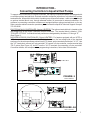
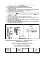
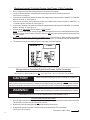
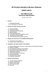
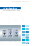
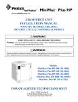
&7
— Instructions —
CONNECTING EXTERNAL
CONTROLLERS
to
AQUACAL HEAT PUMPS
2737 24th Street North
St. Petersburg, FL 33713
727-823-5642
www.aquacal.com
PN: LTP0050
rev 1b
(Effective 12/28/10)
1/7/041
Table of Contents
Page
Introduction to Connecting Controllers to AquaCal Heat Pumps ......3
Personal Safety and Equipment Precautions .................................4
External Controller Overview ..................................................4
Interface Method #1, 2-Wire Controllers ...........................................4
AquaLink 2, 4, 8, and all Aqualink “RS” Series Controllers ..........4
Compool CP3400, CP3600 and CP3800 Controllers ...................4
Interface Method #2, 3-Wire Controllers ...........................................5
AquaSwitch Controllers .........................................................5
Compool CP30 and CP100T Controllers ...................................5
All Intermatic “Air Force” Series Controllers .............................5
All “Air Touch” Controllers ......................................................5
“Universal Controller” by AquaCal ...........................................5
Pentair/Compool “Easy Touch” Controllers ...............................5
Limited Function Controllers and Devices ....................................7
(AquaCal “Call-Flex” Modules & External Flow Switch Applications)
2
INTRODUCTION...
Connecting Controllers to AquaCal Heat Pumps
To support direct connection of external controllers, the majority of AquaCal heaters are equipped with
a controller options terminal block. External controller connection instructions, for heaters with options
terminal blocks, follow within this booklet. A smaller group of AquaCal heaters—while not equipped with
an options terminal block—can, through alternate means, be connected to external controllers. For
guidance in connecting controllers to heaters not equipped with an options terminal block, or for any
other controller related connection questions, please contact the AquaCal Technical Support Group at:
727-823-5642.
ELECTRONICALLY CONTROLLED (Analog) HEATERS: The options terminal block is located on the
low-voltage side of the heater’s electrical controls enclosure. The terminal block is labeled: “CONTROLLER OPTIONS.” Individual terminal positions are designated by the letters “A” through “E”
(See Figure-1).
MICROPROCESSOR CONTROLLED (Digital) HEATERS: For heaters equipped with an HP7R or
HP7 microprocessor, the options terminal block is located on the low-voltage side of the electrical
enclosure, on the microprocessor printed circuit (PC) board; option terminals are labeled: “X-Y-Z.” Use
the “Y-Z” terminals to connect a 2-wire controller. To connect a 3-wire controller, use the terminal strip
“FS-2” points (See Figure-1A); do NOT use the “X-Y-Z” terminals for connecting a 3-wire controller.
Connection details, and microprocessor programming instructions, follow later in this booklet.
A-B-C-D-E
A-B-C-D-E
FIGURE-1
ANALOG CONTROL
X-Y-Z
FS-2
FIGURE-1A
DIGITAL CONTROL
3
Personal Safety and Equipment Precautions
WARNING!
Failure to heed the following may result in permanent injury or death.
Installation by unqualified persons may result in hazards to installer and others. These instructions are intended for use by qualified installation technicians, familiar with electrical service industry safety standards and
methods. Installation to be performed by qualified individuals only. Follow all applicable codes and standards.
DISCONNECT ALL ELECTRICAL POWER PRIOR TO BEGINNING WORK.
WARNING!
WARNING!
Failure to heed the following may result in permanent injury or death.
SPECIAL NOTE... CONNECTING 3-WIRE CONTROLLERS TO DIGITAL HEAT PUMPS
Never connect a 3-wire controller to the heat pump “X-Y-Z” options terminals. Connect only to the “FS-2”
points on the microprocessor terminal strip. Connecting to the “X-Y-Z” options terminals may disable the heat
pump water temperature controls.
CAUTION!
Failure to heed the following may result in damage to equipment.
Incorrect connection of wiring may damage heat pump or the pool/spa equipment. Damage to equipment
caused by incorrect wiring connections is not covered under the equipment warranty. If uncertain of the correct
wiring methods, contact AquaCal Technical Support Group before continuing installation: (727) 823-5642.
External Controller Connection Overview
Most external controllers have similar features. However, there are two general interface connection categories:
Interface #1, using 2-wires; or Interface #2, using 3-wires. Shown within these instructions—beginning with
Interface Method #1 (2-wire)—are the two interface methods and corresponding model designations of typical
external controllers used in the pool/spa industry.
INTERFACE METHOD #1
Representative Controllers Using a 2-Wire Connection to Heat Pump
—CONTROLLERS EQUIPPED WITH OWN THERMOSTATS... USE HEAT PUMP A-B OR Y-Z TERMINALS —
JANDY
Aqualink
All Aqualink 2, 4, and 8 Series
All Aqualink RS Series
PENTAIR
Compool
CP3400, CP3600, & CP3800
Intellitouch
All IT Series
Electromechanically-Controlled (Analog) Heat Pumps: 2-Wire Connection
(See Figure-2, Next Page)
1. Run (18-gage minimum) low-voltage wiring from controller to heat pump.
2. Locate “Controller Options” terminal block inside heat pump electrical controls enclosure
(See Figure-1 on Page-3).
3. Connect wiring from the controller’s low-voltage heater control terminals to heat pump “Controller Options”
terminals designated “A” and “B” (See Figure-2 on Page-5).
4. Turn heat pump thermostats all the way down.
5. Set heat pump thermostat mode switch to OFF position.
6. The external controller’s thermostats are now ready to control the heat pump.
4
Microprocessor-Controlled (Digital) Heat Pumps: 2-Wire Connection
(See Figure-2A)
1. Run (18-gage minimum) low-voltage wiring from controller to heater.
2. Locate microprocessor PC board inside heat pump electrical controls enclosure
(See Figure-1A on Page-3).
3. Connect wiring from external controller’s low-voltage heater control terminals to heat pump microprocessor board options terminal block; use terminals: “Y” and “Z” (See Figure-2A).
4. Reestablish electrical power and water flow to heater.
5. Turn “POOL” thermostat to OFF position by pressing and holding the “DOWN” key on heater control
panel (set temperature below 60-degrees). Then press “POOL/SPA” key once to select SPA thermostat.
Set SPA thermostat to OFF position by pressing and holding “DOWN” key on heater control panel (set
temperature below 60-degrees).
6. Simultaneously press and hold “UP” and “Down” keys until “CF1” is displayed.
7. While “CF1” is displayed, press POOL/SPA key repeatedly until “LOC” is displayed. Now press “UP” key,
repeatedly, until “050” is displayed.
8. Press POOL/SPA key repeatedly until “JAO” is displayed. Press “UP” key repeatedly until “2” is displayed. WAIT... press no other buttons/keys.
9. After a delay of approximately 25-seconds, water temperature will display. The external controller-toheater interface is now ready to test and operate.
FIGURE-2
FIGURE-2A
2-WIRE
DIAGRAMS
INTERFACE METHOD #2
Controllers Using a 3-Wire Connection to Heat Pump
(C-D-E OR FS-2 TERMINALS)
CONTROLLERS NOT EQUIPPED WITH OWN THERMOSTATS.
(THESE CONTROLLERS SIMPLY SELECT THE HEATER’S THERMOSTATS)
Intermatic
”Air Force”
Series
Controllers
Air Touch
Controllers
Universal
Controller by
AquaCal
Pentair/Compool
all “Easy Touch”
Series
Jandy
AquaSwitch
Compool
CP30
CP100T
SEE NEXT PAGE FOR STEPS TO BE FOLLOWED FOR INTERFACE METHOD #2
5
Electromechanically-Controlled (Analog) Heat Pumps: 3-Wire Connection
1. Run (18-gage minimum) low-voltage wiring from controller to heat pump.
2. Locate “Controller Options” terminal block inside heat pump electrical controls enclosure
(See Figure-1 on Page-3).
3. Connect one conductor from external controller low-voltage heater control terminal: “COM/OFF,” to “Controller
Options” terminal “C” (See Figure-3).
4. Connect one conductor from external controller low-voltage heater control terminal: “LOW/POOL,” to
“Controller Options” terminal “D” (See Figure-3).
5. Connect one conductor from external controller low-voltage heater control terminal: “HIGH/SPA,” to “Controller
Options” terminal “E” (See Figure-3).
6. Set heat pump thermostat selector switch to OFF position.
NOTE: Thermie, Sun Power, and Sol Power model heat pumps do not use a thermostat selector switch.
On these models, do NOT set the “ON/OFF” switch to OFF; the heater will not operate with this switch in
the OFF position.
7. NOTE- Thermie, Sun Power, and Sol Power Models (only): Disconnect wire :”W24” (heating only models)
and wire: “W27” (Icebreaker (reversing) models) from terminal “C” of “Controller Options” terminal block.
8. The external controller-to-heater interface is now ready to test and operate.
FIGURE-3
3-WIRE
--------------------------------------------------------------------------------Microprocessor-Controlled (Digital) Heat Pumps: 3-Wire Connection
FS-2 CONNECTION: REQUIRED METHOD FOR ALL
CAUTION!
DIGITAL
HEAT PUMPS... ACTUALLY USES ONLY TWO (2) WIRES
Failure to heed the following may result in damage to equipment.
Only non-powered circuits shall be connected to the microprocessor “FS-2” terminals; never connect outside
power sources to the microprocessor. Connection of energized wiring may damage the heat pump controls.
Damage to equipment, caused by incorrect wiring connections, is NOT covered under the equipment warranty.
WARNING!
Failure to heed the following may result in permanent injury or death.
— DISCONNECT ALL ELECTRICAL POWER PRIOR TO BEGINNING WORK —
Connections Between Heater and Controller
1. Run (18-gage minimum) low-voltage wiring to common (C) and spa connections (H) of external controller.
Third (POOL) wire from controller will not be required.
2. Route wires into low-voltage portion of heat pump electrical enclosure.
3. Using female spade connectors, connect wires at microprocessor FS2 connections
(See Figure-1A on Page-3).
CONTINUED
6
ON
NEXT PAGE
Microprocessor-Controlled (Digital) Heat Pumps: 3-Wire Connection (continued):
1.
2.
3.
4.
5.
6.
7.
8.
9.
1.
2.
3.
Programming Heat Pump Microprocessor
Make sure pool water pump is on.
Restore electrical power to heat pump.
Press and hold “UP” and “DOWN” keys, simultaneously, until “CF1” displays.
At “Pool/Spa” key, toggle until “LOC” appears.
Press “UP” key; go to “50.”
At “Pool/Spa” key, toggle until “FS2” appears.
Press “UP” key twice. The number “1” should display.
WAIT... Press no further buttons; the display should revert to water temperature within approximately
25-seconds.
External controller-to-heater interface is ready to test and use.
Operation
Set desired POOL and SPA water temperatures at heat pump controls.
When external controller selects POOL, the FS-2 circuit will be open; the heat pump controls will default
to the POOL water temperature setting.
When the external controller selects SPA, FS-2 circuit will be closed; heat pump controls will select SPA
water temperature setting.
Limited Function Controllers & Devices
In addition to use with full-function controllers, AquaCal heaters are designed to accept control from devices
having specific and limited uses. These devices are generally used in applications where a full-function pool/spa
equipment controller is not part of the pool/spa installation. Further, in some instances, the use of an external flow
switch—in lieu of the pressure switch normally supplied with the heater—may be indicated due to specific site
conditions.
The most common of these limited use devices are listed below, along with an explanation on their application.
While the actual installation instructions are not detailed, here, when purchased in kit-form from AquaCal, the
devices come supplied with full instructions. Should further information or a set of instructions be desired, please
contact AquaCal per the instructions shown at the bottom of this page.
CALL-FLEX KIT: The Call-Flex option is installed to automatically adjust the run time of the water circulator
pump, and heater, based upon changing weather conditions. Without Call-Flex, as weather conditions grow
progressively cooler during winter months, or when unusually cold weather occurs, the run duration of the circulator pump may require manual adjustments to permit the heater to maintain or reattain desired water temperature
(the water pump must be running in order for the heater to operate). Likewise, without Call-Flex, one must
remember to reset the pump run controls following the cold weather event. The Call-Flex option greatly reduces
the need for seasonal, manually-made, pump run time adjustments.
The Call-Flex option is available through AquaCal, and can be installed during original site construction, or, as an
addition to an existing installation. For use with an analog-controlled heater, use Call-Flex Kit part number: 0030;
the part number for analog kit instructions is: LTP0012. For use with a digitally-controlled heater, use Call-Flex Kit
#0030LEDS; the part number for the digital kit instructions is: LTP0013.
EXTERNAL FLOW SWITCH KIT: There are several applications where it may be desirable to incorporate an
external flow switch into the design of a swimming pool and/or spa installation. Following are the primary applications of an external flow switch:
1. Automatic POOL/SPA Thermostat Switching;
2. Pool/Spa Elevation Higher than Heater (resulting in heater operating without water flow);
3. Two-Speed Pump in Use (and low-speed water pressure will not properly activate heater water pressure
switch).
AquaCal supplies an External Flow Switch Kit, part number: 0040S. The kit instruction part number is: LTP0014.
Obtaining Kit Technical Support or Copy of Kit Instructions
To Obtain a Copy of Kit Instructions: contact AquaCal Customer Support at: 727-823-5642. Ask for the specific
set of instructions referencing the “LTP” number provided above. For Kit Technical Support: contact AquaCal
Technical Support Group at: 727-823-5642. Ask to speak with a Technical Support agent; reference the kit being
worked with by description and part number listed above.
7
2737 24th St. North
St. Petersburg, FL 33713
1-727-823-5642
PROBLEMS ?
CALL US....
AQUACAL TECHNICAL SUPPORT GROUP
727-823-5642
8