1
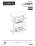
Operator’s Manual
3/8-in. Variable Speed / Reversible
9
Cordless Drill / Driver
1
3
5
7
9
1
3
5
7
Model No. 172.10300 9.6 Volt
Model No. 172.10400 12.0 Volt
96
®
C
US
3025736
Conforms to UL 60745-1
and UL 60745-2-1
Certified to
CAN/CSA-C22,
2NO.60745-1-04,
NO.60745-2-1-04
LIS T E D
CHARGE BATTERY
BEFORE FIRST USE
CAUTION:
Read, understand and
follow all Safety Rules and Operating Instructions
in this Manual before using this product.
Sears, Roebuck and Co.,
Hoffman Estates, IL 60179 U.S.A.
Visit our Craftsman® website:
www.craftsman.com
• WARRANTY
• SAFETY
• UNPACKING
• DESCRIPTION
• OPERATION
• ADJUSTMENTS
• MAINTENANCE
SAFETY SYMBOLS
TABLE OF CONTENTS
Warranty……………........................................................…………………………..Page
2
Safety Symbols……........................................................……………………….….Page
3
Safety Instructions…........................................................………………………….Pages 4 - 10
Unpacking ………….........................................................………………………….Page 11
Description ......................................................………………………………………Pages 12 - 13
Operation ………………………………………........................................................Pages 14 - 22
Maintenance..........................................................................................................Pages 22 - 24
Accessories...........................................................................................................Pages 24 - 25
Repair Parts..........................................................................................................Pages 26 - 31
Sears Repair Parts Phone Numbers.....................................................................Back Cover
The purpose of safety symbols is to attract your attention to possible dangers.
The safety symbols, and the explanations with them, deserve your careful
attention and understanding. The symbol warnings DO NOT by themselves
eliminate any danger. The instructions and warnings they give are no substitutes
for proper accident prevention measures.
! WARNING: BE SURE to read and understand all safety instructions in
this manual, including all safety alert symbols such as “DANGER”, “WARNING”
and “CAUTION”, BEFORE using this tool. Failure to follow all instructions
listed below may result in electric shock, fire and/or serious personal injury.
SYMBOL MEANING
!
SAFETY ALERT SYMBOL: Indicates DANGER, WARNING, OR
CAUTION. May be used in conjunction with other symbols or pictographs.
!
DANGER
!
WARNING
!
CAUTION
ONE YEAR FULL WARRANTY ON COMPANION TOOL
If this Companion tool fails due to a defect in material or workmanship within one year from
the date of purchase, RETURN IT TO ANY SEARS STORE OR OTHER CRAFTSMAN
OUTLET IN THE UNITED STATES FOR FREE REPLACEMENT.
This warranty does not include expendable parts such as lamps, batteries, bits or blades.
This warranty is void if this tool is used for commercial or rental purposes.
This warranty gives you specific legal rights, and you may also have other rights which
vary from state to state.
Sears, Roebuck and Co., Hoffman Estates, IL 60179
Failure to obey this safety warning WILL result in death or
serious injury to yourself or to others. Always follow the
safety precautions to reduce the risk of fire, electric shock
and personal injury.
Failure to obey this safety warning CAN result in death or
serious injury to yourself or to others. Always follow the
safety precautions to reduce the risk of fire, electric shock
and personal injury.
Failure to obey this safety warning MAY result in personal
injury to yourself or others or property damage. Always
follow the safety precautions to reduce the risk of fire,
electric shock and personal injury.
DAMAGE PREVENTION AND INFORMATION MESSAGES
These inform user of important information and/or instructions that could lead to
equipment or other property damage if not followed. Each message is preceded by the
word “NOTE:” as in the example below:
SAVE THESE INSTRUCTIONS!
READ ALL INSTRUCTIONS!
NOTE: Equipment and/or property damage may result if these instructions
are not followed.
! WARNING: Some dust created by using power tools contains chemicals known to
the State of California to cause cancer and birth defects or other reproductive harm.
2
! WARNING: The operation of any drill / driver can
result in foreign objects being thrown into your eyes,
which can result in severe eye damage. Before beginning
power tool operation, ALWAYS wear safety goggles or
safety glasses with side shield and a full-face shield
when needed. We recommend a Wide Vision Safety
Mask for use over eyeglasses or standard safety glasses
with side shield, available at Sears Stores or other
Craftsman Outlets.
3
10-4-07 Drill
10300-10400
SAFETY INSTRUCTIONS
!
SAFETY INSTRUCTIONS cont.
WARNING: BE SURE to read and understand all instructions in this
manual before using this drill / driver. Failure to follow all instructions may result
in electric shock, fire and/or serious personal injury.
WORK AREA SAFETY
1. Keep your work area clean and well lit. Cluttered workbenches and dark areas
invite accidents.
2. DO NOT operate power tools in explosive atmospheres, such as in the presence
of flammable liquids, gases, or dust. Power tools create sparks which may ignite
the dust or fumes.
3. Keep bystanders, children and visitors away while operating a power tool.
Distractions can cause you to lose control.
4. Make your workshop childproof with padlocks and master switches. Lock tools
away when not in use.
PERSONAL SAFETY
1. KNOW your cordless drill / driver. Read the operator’s manual carefully. Learn the tool’s
applications and limitations, as well as the specific potential hazards related to this tool.
2. STAY ALERT, watch what you are doing and use common sense when operating
a power tool.
3. DO NOT use power tools while tired or under the influence of drugs, alcohol or
medication. A moment of inattention while operating power tools may result in
serious personal injury.
4. DRESS properly. DO NOT wear loose clothing or jewelry. Pull back long hair. Keep
your hair, clothing, and gloves away from moving parts. Loose clothing, or long hair
can be caught in moving parts. Air vents often cover moving parts and should
also be avoided.
5. AVOID accidental starting. Be sure trigger switch is in the “Locked OFF” position
before inserting battery pack. DO NOT carry tools with your finger on the trigger switch.
Carrying tools with your finger on the trigger switch or inserting the battery pack in tools
that have the switch in the “FORWARD” OR “REVERSE” position invites accidents.
6. Do not overreach. Keep proper footing and balance at all times. Proper footing
and balance enables better control of the tool in unexpected situations.
7. ALWAYS SECURE YOUR WORK. Use clamps or a vise to hold work when practical.
It is safer than using your hand and frees both hands to operate tool.
8. USE SAFETY EQUIPMENT. Always wear eye protection. Dust mask, non-skid safety
shoes, hard hat, or hearing protection must be used for appropriate conditions.
4
TOOL USE AND CARE SAFETY
! WARNING: BE SURE to read and understand all instructions before
operating this drill / driver. Failure to follow all instructions listed below may result
in electric shock, fire and/or serious personal injury.
1. ALWAYS use clamps or other practical ways to secure and support the workpiece
to a stable platform. Holding the work by hand or against your body is unstable and
may lead to loss of control.
2. DO NOT force the tool. Use the correct tool and accessory bit for your application.
The correct tool and bit will do the job better and safer at the rate for which it is designed.
3. DO NOT use the tool if trigger switch does not turn it “On” or “Off”. Any tool that
cannot be controlled with the trigger switch is dangerous and must be repaired.
4. REMOVE the battery pack from the drill / driver or place the forward / reverse
selector switch with power lock-off in the “Lock Off” position before making
any adjustments, changing accessories or storing the tool. Such preventive
safety measures reduce the risk of starting the tool accidentally.
5. STORE idle tools out of the reach of children and other untrained persons.
Tools are dangerous in the hands of untrained users.
6. ALWAYS remove battery pack and store separately when drill / driver
is not being used.
7. When battery pack is not in use, keep it away from other metal objects like:
paper clips, coins, keys, nails, screws, or other small metal objects that can
make a connection from one terminal to the other. Shorting the battery terminals
together may together may cause burns to skin, sparks and/or a fire.
8. MAINTAIN tools with care. Keep cutting tools such as twist drill bits sharp and
clean. Properly maintained tools with sharp cutting edges are less likely to bind and are
easier to use and control.
9. CHECK for misalignment or binding of moving parts, breakage of parts, and any
other condition that may affect the tool’s operation. If damaged, have the tool serviced
before using. Many accidents are caused by poorly maintained tools.
10. USE ONLY accessories that are recommended for this tool. Accessories that may
be suitable for one tool may become hazardous when used on another tool.
See page 24 for accessories.
11. Keep the tool and its handle dry, clean and free from oil and grease. Always use
a clean cloth when cleaning. Never use brake fluids, gasoline, petroleum-based
products, or any strong solvents to clean your tool. Following this rule will reduce
the risk of loss or control and deterioration of the enclosure plastic.
5
10-4-07 Drill
10300-10400
SAFETY INSTRUCTIONS cont.
SAFETY INSTRUCTIONS cont.
ELECTRICAL SAFETY
! WARNING: BE SURE to read and understand all instructions before
operating this drill/driver. Failure to follow all instructions listed below may
result in electric shock, fire and/or serious personal injury.
A battery operated tool with integral batteries or a separate battery pack must be recharged
only with the specified charging stand/transformer for the battery. A charger that may be
suitable for one type of battery may create a risk of fire when used with another battery.
1. Use battery operated drill/driver only with the specifically designated battery
pack listed. Use of any other battery pack may create a risk of fire.
2. Use battery pack only with the specifically designated charging stand/transformer listed.
MODEL
TRANSFORMER
172.10300 (9.6V) CDT109JU-48 (HD-DC12-200)
172.10400 (12.0V) CDT112JU-48 (HD-DC15-200)
CHARGING STAND
BATTERY PACK
CDT109JU-49
CDT109JU-50 (ABP309)
CDT112JU-49
CDT112JU-50 (ABP312)
3. Do not abuse the power cord on the charging stand/transformer. Never carry the
charging stand/transformer by its power cord. Never pull the power cord to remove the
transformer from the power outlet. Damage to the cord or charging stand/transformer
could occur and create an electric shock hazard. Keep cord away from heat, oil, sharp
edges or moving parts. Replace damaged cords immediately. Damaged cords increase
the risk of electric shock.
SAFETY SYMBOLS FOR YOUR TOOL
The label on your tool may include the following symbols.
V.......................................................................Volts
A......................................................................Amps
Hz....................................................................Hertz
W.....................................................................Watts
min..................................................................Minutes
....................................................................Alternating current
.................................................................Direct current
no ....................................................................No-load speed
....................................................................Class II construction, Double Insulated
.../min..............................................................Revolutions or Strokes per minute
! .....................................................................Indicates danger, warning or caution.
It means attention! Your safety is involved.
SERVICE SAFETY
1. If any part of this cordless drill / driver or charging stand/transformer is missing
or should break, bend, or fail in any way; or should any component fail to perform
properly: have the missing, damaged or failed parts replaced BEFORE resuming operation.
2. Tool service must be performed only at a Sears Parts and Repair Center. Service or
maintenance performed by unqualified personnel could result in a risk of injury.
3. When servicing a tool, use only identical replacement parts. Follow instructions
in the maintenance section of this manual. Use of unauthorized parts or failure to
follow maintenance instructions may create a risk of electric shock or injury.
6
SPECIFIC SAFETY RULES FOR CORDLESS DRILL / DRIVERS
1. Know your cordless drill / driver. Read operator’s manual carefully. Learn its
applications and limitations, as well as the specific potential hazards related to
this tool. Following this rule will reduce the risk of electric shock, fire, or
serious injury.
2. BE SURE that twist drill bits, screwdriver bits and other accessory attachments are
properly and securely mounted in the chuck jaws BEFORE operating the drill / driver.
3. ALWAYS carefully inspect the material you are going to drill/drive into. Drilling/driving
into nails, pipes and electrical wires can cause serious personal injury.
4. HOLD DRILL / DRIVER by insulated gripping surfaces (handles) when performing
an operation where the tool may drill/drive into hidden wiring. Contact with a “live”
wire will make the exposed metal parts of the tool “live” and shock the operator.
5. NEVER hold the piece being drilled in your hands or across your legs.
It is important to support and clamp the workpiece properly in order to minimize body
exposure, bit binding, or loss of control.
6. Maintain a firm grip on the drill/driver to resist starting torque.
7. Use sharp accessory bits only. For drilling in WOOD use twist drill bits, spade bits,
or power auger bits. For METAL use high-speed steel twist drill bits. For MASONRY
use carbide-tipped bits. For PLASTIC use low drilling speeds for material with a low
melting point. For SCREWDRIVING use the proper size screwdriving bit for the
screwdriving application such as Phillips, slotted and square recess bits.
8. BE SURE the material to be drilled is stationary, anchored or clamped firmly. If drilling
thin material, use a back-up block to prevent damage to the material.
9. ONLY USE the specifically designated battery pack that was included with this
drill / driver and charging stand / transformer. Use of any other battery packs may
create a risk of injury and fire.
10. Cordless tools do not have to be plugged into an electrical outlet; therefore,
they are always in operating condition. Be aware of possible hazards when not
using your battery operated tool or when changing accessories. Following this
rule will reduce the risk of electric shock, fire, or serious personal injury.
11. Do not place battery tools or their batteries near fire or heat. This will reduce the
risk of explosion and possible injury.
12. Do not crush, drop or damage battery pack. Never use a battery pack or charging
stand/transformer that has been dropped or received a sharp blow. A damaged
battery is subject to explosion. Properly dispose of a dropped or damaged battery
immediately.
13. Batteries vent hydrogen gas and can explode in the presence of a source of
ignition, such as a pilot light. To reduce the risk of personal injury, never use any
cordless product in the presence of open flame. An exploded battery can propel debris
and chemicals. If exposed, flush with water immediately.
7
10-4-07 Drill
10300-10400
SAFETY INSTRUCTIONS cont.
SPECIFIC SAFETY RULES FOR CORDLESS DRILL / DRIVERS cont.
14. Do not charge battery pack in a damp or wet location. Following this rule will
reduce the risk of electric shock.
15. For best results, your battery pack should be charged in a location where the
temperature is more than 50°F but less that 100°F. Do not store battery outside or
in vehicles.
16. Under extreme usage or temperature conditions, battery leakage may occur.
If liquid comes in contact with your skin, wash immediately with soap and water,
then neutralize with lemon juice or vinegar. If liquid gets into your eyes, flush
them with clean water for at least 10 minutes, then seek immediate medical
attention. Following this rule will reduce the risk of serious personal injury.
17. Save these instructions. Refer to them frequently and use them to instruct others
who may use this tool. If you loan someone this tool, loan them these instructions also
to prevent misuse of the product and possible injury.
SAFETY RULES FOR BATTERY CHARGER STAND / TRANSFORMER
! WARNING: READ AND UNDERSTAND ALL INSTRUCTIONS. Failure to
follow all instructions listed below may result in electric shock, fire and / or
serious personal injury.
NOTE: Before using battery charging stand/transformer, read all instructions
and cautionary markings in this manual, on battery charging stand/transformer,
battery pack, and drill/driver using battery pack to prevent misuse of the
products and possible injury or damage.
! CAUTION: USE ONLY the specifically designated charging
stand/transformer that was supplied with this drill/driver when charging the
battery pack. The use of any other charging stand/transformer could damage
the battery pack and create a hazardous condition.
! CAUTION: To reduce the risk of electric shock or damage to the charging
stand/transformer and battery pack, charge only the specifically designated
Companion battery pack that was included with this drill/driver and the charging
stand/transformer. Charging other types of battery packs may cause them to
burst, causing personal injury and damage.
1. Do not use the charging stand/transformer outdoors or expose to wet or damp
conditions. Water entering charging stand will increase the risk of electric shock.
2. Use of an attachment with this charging stand/transformer that is not recommended
may result in a risk of fire, electric shock, or injury to persons.
8
SAFETY INSTRUCTIONS cont.
SAFETY RULES FOR BATTERY CHARGER STAND / TRANSFORMER cont.
3. Do not abuse the cord on the charging stand. Never carry the charging stand/
transformer by its power cord. Never pull the power cord to remove the transformer from the
power outlet. Damage to the cord or charging stand/transformer could occur and create an
electric shock hazard. Keep cord away from heat, oil, sharp edges or moving parts. Replace
damaged cords immediately. Damaged cords increase the risk of electric shock.
4. Make sure cord is located so that it will not be stepped on, tripped over, come in
contact with sharp edges or moving parts, heat, oil, or otherwise subjected
to damage or stress. This will reduce the risk of accidental falls, which could cause
injury, and damage to the cord which could result in electric shock.
5. Keep cord and charging stand/transformer away from heat to prevent damage to
housing or internal parts.
6. Do not let gasoline, oils, petroleum-based products, etc. come in contact with
plastic parts. They contain chemicals which can damage, weaken or destroy plastic.
7. An extension cord should not be used unless absolutely necessary. Use of improper
extension cord could result in a risk of fire and electric shock. If an extension cord must be
used, make sure: a) That pins on plug of extension cord are the same number, size and
shape as those of transformer on charger, b) That extension cord is properly wired and in
good electrical condition, and c) That you use a proper extension cord. ONLY use cords
listed by Underwriters Laboratories (UL). Other extension cords can cause a drop in line
voltage, resulting in a loss of power and overheating of charging stand/transformer. An
AWG (American Wire Gauge) size of at least 14-gauge is recommended for an extension
cord of 25-ft. or less in length. Use 12-gauge for an extension cord of 50-ft. Extension
cords 100-ft. or longer are not recommended.
8. INSPECT tool cords for damage. Do not operate charging stand with a damaged cord or
transformer, which could cause shorting and electric shock. Have damaged tool cords
repaired at a Sears Service Center.
9. Do not operate charging stand/transformer if it has received a sharp blow, been dropped,
or otherwise damaged in any way. Take it to an authorized serviceman for electrical check to
determine if the charging stand/transformer is in good working order.
10. Do not disassemble charging stand/transformer. Take it to a Sears Parts and Repair Center
when service or repair is required. Incorrect reassembly may result in a risk of electric
shock or fire.
11. Disconnect charging stand/transformer from the power supply when not in use.
This will reduce the risk of electric shock or damage if metal items should fall into the opening in
the charging stand. It also will help prevent damage during a power surge.
12. Risk of electric shock. Do not touch un-insulated portion of output connector or un-insulated
battery terminal.
13. Save these instructions. Refer to them frequently and use them to instruct others who may use
this tool. If you loan someone this tool, loan them these instructions also to prevent misuse of the
product and possible injury.
9
10-4-07 Drill
10300-10400
PACKING LIST:
1. Drill / Driver with Battery Pack (in Drill)
7
9
2. Charging Stand / Transformer
n
Companio
1
! WARNING: Some dust created by using power tools contains chemicals
known to the State of California to cause cancer and birth defects or other
reproductive harm.
Some examples of these chemicals are:
• Lead from lead-based paints.
• Crystalline silica from bricks and cement and other masonry products.
• Arsenic and chromium, from chemically treated lumber.
Your risk from these exposures varies, depending upon how often you do
this type of work. To reduce your exposure to these chemicals:
• Work in a well-ventilated area.
• Work with approved safety equipment, such as those dust masks that are specially
designed to filter out microscopic particles.
Avoid prolonged contact with dust from power sanding, sawing, grinding,
drilling and other construction activities. Wear protective clothing and wash
exposed areas with soap and water. Allowing dust to get into your mouth,
eyes, or lay on the skin may promote absorption of harmful chemicals.
This product has been shipped completely assembled.
1. Carefully remove the tool and accessories from the box.
2. Make sure that all items listed in the packing list are included.
3. Inspect the tool carefully to make sure no breakage or damage occurred
during shipping.
4. Do not discard the packing material until you have carefully inspected and
satisfactorily operated the tool.
5. If any parts are missing, return to the nearest Sears store or other Craftsman
outlet to have the Drill / Driver replaced.
5
SAFETY RULES FOR BATTERY CHARGER STAND / TRANSFORMER cont.
UNPACKING
3
SAFETY INSTRUCTIONS cont.
! WARNING: Use of this tool can generate and/or disburse dust, which
may cause serious and permanent respiratory or other injury. Always use
NIOSH/OSHA approved respiratory protection appropriate for the dust exposure.
Direct particles away from face and body.
3. 2 Double Ended
Screwdriver Bits
ADDITIONAL RULES FOR SAFE OPERATION
! WARNING: BE SURE to read and understand all instructions. Failure to
follow all instructions listed may result in electric shock, fire and/or serious
personal injury.
1. Know your drill / driver. Read operator’s manual carefully. Learn the applications
and limitations, as well as the specific potential hazards related to this tool. Following
this rule will reduce the risk of electric shock, fire or serious injury.
2. ALWAYS wear safety glasses or eye shields when using this drill / driver.
Everyday eyeglasses have only impact-resistant lenses; they are NOT safety glasses.
3. PROTECT your lungs. Wear a face mask or dust mask if the operation is dusty.
4. PROTECT your hearing. Wear appropriate personal hearing protection during use.
Under some conditions noise from this product may contribute to hearing loss.
5. SAVE THESE INSTRUCTIONS. Refer to them frequently and use them to instruct
others who may use this tool. If someone borrows this tool, make sure they have
these instructions also.
4. Operator’s Manual
! WARNING: If any parts are missing do not operate this tool until the
missing parts are replaced. Failure to do so could result in possible serious
personal injury.
! WARNING: Do not attempt to modify this tool or create accessories not
recommended for use with this tool. Any such alteration or modification is misuse
and could result in a hazardous condition leading to possible serious personal
injury
! WARNING: To prevent accidental starting that could cause serious
personal injury, always remove the battery pack from the tool when
assembling parts.
10
11
10-4-07 Drill
10300-10400
DESCRIPTION cont.
DESCRIPTION
KNOW YOUR CORDLESS DRILL / DRIVER (Fig. 1)
NOTE: Before attempting to use this product, familiarize yourself with all operating
features and safety rules.
Bubble Level
9
Torque Adjustment Collar
5
7
Keyless Chuck
Companion
3
Chuck Jaws
1
Transformer
Trigger Switch
Charging Stand
On-Tool Bit
Storage
Red LED
Light
Slotted / Square Drive
Green LED
Light
Forward/
Reverse
Selector
Switch with
Power
Lock-Off
This Cordless Drill / Driver has the following features cont.:
2. Keyless Chuck allows you to hand-tighten or loosen and release accessory bits in the
chuck jaws without a chuck key.
3. Torque Adjustment Collar provides you with 15 + 1 different torque settings, ideal for
driving different types of screws into different types of materials, and a setting for heavy
(twist bit) drilling (most torque).
4. Electric Brake stops the bit rotation as soon as the trigger switch is released, ideal when
driving screws.
5. Bubble Level help provide more accurate vertical and horizontal drilling and driving.
6. Magnetic Bit Tray for holding screwdriver bits. This tray is located at the front base of the
drill / driver’s handle and is handy for keeping the bits you are using on a project ready for
use.
7. Soft-Grip Handle Insert provides positive gripping for maximum control and comfort.
8. Includes 2 Double Ended Scredriver Bits, 1 phillips and 1 slotted / square drive
PRODUCT SPECIFICATIONS
Latch to
Release
Battery
Pack
Battery Pack
Phillips
2 Double ended Screwdriver Bits
Model No. 10300:
Chuck
3/8-in. keyless
Clutch
15 + 1 Position
Motor
9.6 Volt
Torque
Max. 80 in.-lbs.
Switch
Variable Speed
Charger Input
120V, 60Hz AC
No Load Speed
0-500/min.
Charge Rate
3 – 5 Hours
Model No. 10400:
Chuck
This Drill / Driver has many features for making its use more pleasant and enjoyable. Safety,
performance and dependability have been given top priority in the design of this product,
making it easy to maintain and operate.
3/8-in. keyless
Clutch
15 + 1 Position
Motor
12.0 Volt
Torque
Max. 85 in.-lbs.
Switch
Variable Speed
Charger Input
120V, 60Hz AC
0-500/min.
Charge Rate
3 – 5 Hours
No Load Speed
This Cordless Drill / Driver has the following features:
1. Forward / Reverse Selector Switch with Power Lock-Off This switch is located above
and to the rear of the trigger switch. This switch has embossed arrows which show bit
rotation (forward or reverse). Push switch completely to left or right for desired rotation.
Push switch to center position to lock power off. This “lock power off” position helps
reduce the possibility of accidental starting when your drill / driver is not in use or you
are changing accessory bits.
12
13
10-4-07 Drill
10300-10400
OPERATION
OPERATION cont.
FORWARD / REVERSE SELECTOR SWITCH with POWER LOCK-OFF (Fig. 2)
CHARGING THE BATTERY PACK (Fig. 4 and 4a)
Fig. 2
The battery pack for this tool has been shipped in a low charge condition to prevent
possible problems. Therefore, you should charge overnight prior to use.
a.
POWER LOCK-OFF
b.
c.
FORWARD
NOTE: Batteries will not reach full charge the first time they are charged.
Allow several cycles (operation followed by recharging) for them to become
fully charged.
REVERSE
The direction of bit rotation is forward or reverse and is controlled by a selector switch
located above and to the rear of the trigger switch. When holding the drill / driver in the
normal operating position, (and viewed from the back of the drill/driver see Fig 2 a, b, c),
the selector switch should be positioned (pushed) all the way to the RIGHT, for
FORWARD (b) or normal drilling / driving, and positioned (pushed) all the way to the LEFT
for REVERSE (c) to remove drill bits and back out screws.
The third position for the selector switch is located in the CENTER (a). This position keeps the
trigger switch from working, locking the power “OFF”. Setting the selector switch in the “OFF” or
CENTER position helps reduce the possibility of accidental starting when the tool is not in use.
! CAUTION: To prevent gear damage, always allow the chuck to come to
a complete stop before changing the direction of rotation.
Fig. 3
REMOVE BATTERY PACK FROM
DRILL / DRIVER (Fig. 3)
1. Place the Forward / Reverse Selector
Switch with Power Lock-Off into the
center position to lock the power off
(see Fig. 2, above).
1. Charge battery pack only with the charging
Fig. 4
stand/ transformer that was supplied with
this drill / driver.
2. Make sure power supply is normal
household voltage, 120 volts,
60 Hz, AC only.
3. Connect charging stand’s transformer to power
supply.
4. Place battery pack in charging stand. Align
raised rib on battery pack with groove in
charging stand (See Fig. 4).
5. Press battery pack down into charging stand
making sure contacts are engaged properly.
Fig. 4a
6. The charging stand has two (LED) indicator
lights, one green and one red.
When the charging stand’s transformer is
plugged into a power outlet, the green LED
will light, indicating that the charger is
operating properly.
When a battery pack is put into the charging
stand/transformer, the red LED will light,
indicating that the battery pack is charging
properly (see Fig. 4a).
Both lights will remain “On” as long as
the charging stand/transformer is plugged
in and the battery pack is charging.
Green
LED
Red
LED
Green
LED
When the battery pack is charged and removed from the charging stand, the red light
will go Off. The green LED will stay “On” as long as the charging stand/transformer
is plugged into a power supply and operating properly.
2. Locate the latches on each side of the
battery pack. Depress (squeeze in)
latches and pull battery pack out of
drill.
NOTE: If the charging stand LED lights do not operate properly, or the charging
stand does not charge the battery pack, return the drill/ driver, charging
stand/transformer and battery pack to your nearest Sears store or other
Craftsman outlet to have it replaced.
7. After normal use, 3 hours or less of charging time is required to fully recharge battery
pack. If battery pack is completely discharged, 6 hours or longer of charging time is
required to fully recharge battery pack.
14
15
10-4-07 Drill
10300-10400
OPERATION cont.
OPERATION cont.
CHARGING THE BATTERY PACK cont. (Fig. 4 and 4a)
ELECTRIC BRAKE
8. The battery pack will become slightly warm to the touch while charging. This is normal
and does not indicate a problem.
9. Do not place the charging stand/transformer in an area of extreme heat or cold. It will
work best at normal room temperature.
10. When battery pack becomes fully charged, unplug charging stand/ transformer
from power supply and remove the battery pack.
To stop the drill/driver, release the trigger switch and the electric brake will stop the chuck instantly.
NOTE: This situation only occurs when continuous use of your drill / driver causes the
batteries to become hot. It does not occur under normal circumstances. Refer to
“Charging the Battery Pack” for normal recharging of batteries. If the charging stand
does not charge your battery pack under normal circumstances, return both the battery
pack and charging stand/transformer to your nearest Sears Repair Center for an
electrical check.
INSTALLING THE BATTERY
PACK IN DRILL/DRIVER (Fig. 5)
Fig. 5
To turn the drill ON, push the Forward / Reverse Selector Switch with Power Lock-Off to the
FORWARD or REVERSE location (see arrow direction embossed on switch), and depress
the trigger switch. To turn the drill OFF, release the trigger switch.
Fig. 6
Fig. 6a
Compan
ion
1
1. Place the Forward / Reverse Selector
Switch with Power Lock-Off into the
center position to lock the power off.
2. Place the battery pack into the drill.
Align the raised rib on battery
pack with groove inside the drill.
3. Make sure the latches on each side of
the battery pack “snap” into place, and
the battery pack is secured in the
drill/driver before beginning operation.
TRIGGER SWITCH (Fig. 6 and 6a)
5
When using your tool continuously, the batteries in your battery pack will become hot.
You should let a hot battery pack cool down for approximately 30 minutes before
attempting to recharge.
Avoid running the drill / driver at low speeds for extended periods of time. Running at low
speeds under constant usage may cause the drill/driver to become overheated. If this
occurs, cool the drill / driver by running it without a load and at full speed.
3
CHARGING A HOT BATTERY PACK
NOTE: The drill/driver will not operate unless the Forward/Reverse Selector
Switch with Power Lock-Off is pushed fully to the left (forward) or to the right
(reverse).
Fig. 6b
FORWARD
REVERSE
VARIABLE SPEED (Fig. 6b)
!
CAUTION: When placing battery pack in the tool, be sure raised rib on
battery pack aligns with the bottom of the drill and latches into place properly.
Improper installation of the battery pack can cause damage to internal
components.
The variable speed trigger switch delivers higher speed and torque with increased
pressure on the trigger switch and lower speed with decreased pressure on the trigger
switch.
! WARNING: Cordless Battery Tools are always in operating condition
when the battery pack is installed in the tool. Therefore the Forward / Reverse
Selector Switch with Power Lock-Off should always be in the center position,
locking the power off, when the tool is not in use or when you are carrying
it at your side.
NOTE: You might hear a whistling or ringing noise from the trigger switch when
operating at low speeds. Do not be concerned; this is a normal part of the
switch function.
16
17
10-4-07 Drill
10300-10400
OPERATION cont.
OPERATION cont.
KEYLESS CHUCK (Fig. 7)
15 PLUS 1 ADJUSTABLE TORQUE CLUTCH (Fig. 9, 9a and 9b)
The drill/driver has a keyless chuck which allows you to hand tighten or loosen accessory bits
without the use of a chuck key.
1. Grasp and hold the rear chuck collar with one hand (see Fig. 7).
2. Rotate the front of the chuck with your other hand, clockwise (as viewed from the front
of the chuck), to CLOSE the chuck jaws and tighten (”GRIP”) the accessory bit in the jaws.
3. Rotate the front of the chuck counterclockwise to OPEN the chuck jaws to loosen
(”RELEASE”) the accessory bit from the chuck jaws (see Fig. 7a).
This drill / driver is equipped with an adjustable clutch that has 16 different torque settings.
These torque settings allow you to efficiently perform various drilling and screw driving
applications. To adjust the clutch, hold the handle of the drill / driver with one hand and with
the other hand turn the clutch collar to the left or right (see Fig. 9), and line the desired setting
(number or symbol) up to the embossed arrow on the top of the drill/driver’s motor housing
(see Fig. 9a).
Decrease
Fig. 9
Fig. 9a
OPEN “RELEASE”
5
Fig. 7a
5
3
7
Fig. 7
7
9
NOTE: ON THE VERY FRONT OF THE CHUCK there are “HANDS” that point the
direction to rotate the front of the chuck to “GRIP” or “RELEASE” the accessory
bits.
Com
panio
n
7
9
11
Increase
CLOSE “GRIP”
3
1
5
7
3
9
5
1
1
Com
panio
n
9.6
V
! WARNING: Do not hold the chuck body with one hand and use the power of the
drill / driver to tighten the chuck jaws on the accessory bit. The chuck body could slip in
your hand, or your hand could slip and come in contact with the rotating accessory bit.
This could cause an accident resulting in serious personal injury.
BUBBLE LEVELS (Fig. 8 an 8a)
In order to insure a perfect
right angle when drilling/driving
into a workpiece, you can use
the built-in bubble level on the
back of the drill / driver
(see Fig. 8). The bubble level
is designed to work when
drilling / driving in either a
horizontal or vertical position.
Line the air bubble up in the
appropriate circle, and the
drill/driver is in a perpendicular
angle to the workpiece. This
will insure that you drill/drive
straight into the workpiece.
Fig. 8a
Fig. 8
Use the following guidelines to arrive at a proper torque setting.
Fig. 9b
1–3
4–6
7–9
10 – 12
13 – 15
For driving small screws (least torque)
For driving screws into soft material
For driving screws into soft and hard materials
For driving screws in hard woods
For driving larger screws
For normal to heavy twist drilling into all building materials (most torque)
1. For normal drilling in wood, metal and plastics, turn and set the collar to the drilling
position symbol
2. For screw driving, turn and set the collar to the desired setting 1 through 15. If you are
not sure of the appropriate setting using the guidelines in the chart (Fig. 9b),
proceed as follows;
Align Bubble Level
on Back for Vertical drilling
18
Align Bubble Level on Top
for Horizontal drilling
• Set the collar to the lowest setting, “1”
• Drive and tighten the first screw
• If the clutch ratchets before the screw is tightened, increase the torque setting and
continue to tighten the screw.
• Repeat this process until you reach a torque setting that drives and tightens the screw
without the clutch ratcheting.
• Use that torque setting to drive and tighten the remaining screws.
19
10-4-07 Drill
10300-10400
OPERATION cont.
OPERATION cont.
1. Lock the trigger switch Off by placing the Forward / Reverse Selector Switch with Power
Lock-Off in the Center position.
2. Open or close the chuck jaws to a point where the opening is slightly larger than the bit
size you intend to use. Also, raise the front of the drill slightly to keep the bit from falling
out of the chuck jaws (see Fig. 11 and 12).
3. Insert the accessory bit.
4. Rotate the chuck clockwise to tighten (GRIP) the chuck jaws securely on the bit.
! WARNING: Make sure to insert the accessory bit straight into the chuck
jaws. Do not insert the accessory bit into the chuck jaws at an angle then
tighten, as shown in Figure 13. This could cause the bit to be thrown from
the drill, resulting in possible serious personal injury or damage to the chuck.
NOTE: Rotate the chuck body in the direction of the “HAND POINTING” marked
“GRIP” to tighten the chuck jaws. DO NOT use a wrench to tighten or loosen
the chuck jaws.
Fig. 12
OPEN JAWS
(insert bit)
COUNTER-CLOCKWISE
(Release Bit)
Turn and set the torque clutch collar to the drilling position symbol
desired drill bit into the chuck.
1.
2.
3.
4.
5.
6.
7.
8.
9
9
Fig. 11
OPERATION AS A DRILL (Fig. 14)
5
7
7
9.
1
3
5
CLOCKWISE
(Grip Bit)
3
CLOSE JAWS
(to tighten bit)
1
Com
panio
n
Com
panio
n
9.6
10.
V
Fig. 13
REMOVING BITS (Figs. 11 and 12)
WRONG
11.
Install the battery pack into the drill/driver.
Push the forward /reverse selector switch with power lock-off to the forward position.
For drilling in WOOD, use twist drill bits, spade bits and auger bits.
For drilling in METAL, use high speed twist drill bits. Use a cutting lubricant when drilling
in metals. The exceptions are cast iron and brass, which should be drilled dry.
For drilling in MASONRY, use carbide tipped bits or masonry bits. A smooth, even flow of
dust indicates the proper drilling speed.
Fig. 14
Always apply pressure in a straight line with
the bit. If necessary, use the bubble levels
to drill straight into the workpiece. Use enough
pressure to keep the bit biting, but do not
push hard enough to stall the motor or
deflect the bit.
Hold drill / driver firmly to control the twisting
action of the drill / driver.
Move the drill bit into the workpiece, applying
only enough pressure to keep the bit cutting.
Do not force the drill or apply side pressure
to elongate a hole. Let the tool do the work.
When drilling hard, smooth surfaces, use a
center punch to mark the desired hole
location. This will prevent the drill bit from
slipping off-center as the hole is started.
If the drill/driver stalls, or the bit jams in the
workpiece, it is usually because the
drill / driver is being overloaded. RELEASE
TRIGGER SWITCH IMMEDIATELY and
remove bit from workpiece. Determine cause
of stalling. DO NOT PRESS TRIGGER OFF AND ON IN AN ATTEMPT TO START
A STALLED DRILL / DRIVER – THIS COULD DAMAGE THE DRILL / DRIVER.
Keep the motor running when pulling the bit back out of a drillled hole. This will help
prevent jamming.
5
7
9
1. Lock the trigger switch Off by placing the
Forward / Reverse Selector Switch with
Power Lock-Off in the Center position.
2. Rotate the chuck body counterclockwise
to open the chuck jaws.
3. Remove the accessory bit.
. Install and tighten the
Companion
INSTALLING ACCESSORY BITS (Figs. 11, 12 and 13)
1
3
Companion
NOTE: Rotate the chuck body in the direction of the HAND POINTING marked
RELEASE to loosen the chuck jaws. DO NOT use a wrench to tighten or loosen the
chuck jaws.
20
! WARNING:Be prepared for binding at bit breakthrough. When these situations
occur, drill/driver has a tendency to grab and kick opposite to the direction of rotation
and could cause loss of control when breaking through material. If not prepared, this
loss of control could result in possible serious injury.
NOTE: This drill/driver has an electric brake. When the trigger switch is released, the
chuck stops turning instantly. When the brake is functioning properly, sparks will be
visible through the vent slots on the housing. This is normal and is the action of the brake.
21
10-4-07 Drill
10300-10400
MAINTENANCE
OPERATION cont.
OPERATION AS A SCREWDRIVER
(Fig. 15)
Fig. 15
Turn and set the torque clutch collar to the
desired torque setting, 1 through 15. Install
and tighten the desired fastener accessory
bit into the chuck.
1. Install the battery pack into the drill/driver.
2. Push the forward/reverse selector switch
to the forward position.
3. Follow the guidelines on page 19 to arrive
at the proper torque setting for your job.
4. Make a few practice runs, driving screws in
scrap material, to make sure you have the
clutch set at the proper torque setting for
your job.
5. When all adjustments are correct, drive
and tighten your fasteners.
6. To remove fasteners, push forward/reverse
selector switch to the reverse position.
GENERAL MAINTENANCE
Companion
Avoid using solvents when cleaning plastic parts. Most plastics are susceptible to damage from
various types of commercial solvents and may be damaged by their use. Use clean cloths to
remove dirt, dust, oil and grease, etc.
! WARNING: Do not at any time let brake fluids, gasoline, petroleum-based
products, penetrating oils, etc., come in contact with plastic parts. Chemicals
can damage, weaken or destroy plastic which may result in serious personal
injury.
CHUCK REMOVAL (Figs. 17, 17a and 17b)
5
7
9
Fig. 17
1
3
Companion
7
9
Fig. 17a
Companion
1
3
Your drill/driver comes with 2 double-ended
screwdriver bits, 1 phillips and
1 slotted / square drive. When not in use,
these bits can be stored on the base
The chuck may be removed
and replaced by a new one.
1. Lock the trigger switch by placing the
Forward / Reverse Selector Switch with Power
Lock-Off in center, or OFF position.
2. Insert a 5/16-in. or larger hex key into the jaws
of the chuck of the drill and Tighten the chuck
jaws securely.
3. Tap the hex key sharply with a mallet in a
clockwise direction (see Fig. 17). This will
loosen the screw in the chuck for easy removal.
4. Open the chuck jaws and remove the hex key.
Using a Phillips screwdriver, remove the
chuck screw by turning it in a clockwise
direction (see Fig. 17a).
5
Fig. 16
ON-TOOL BIT STORAGE (Fig. 16)
! WARNING: To avoid serious personal injury, always remove the battery
pack from the tool when cleaning or performing any maintenance.
NOTE: The chuck screw has left hand threads.
MAINTENANCE
! WARNING: When servicing, use only identical Sears replacement parts.
Use of any other part may create a hazard or cause product damage.
5. Insert the hex key back into the chuck and
tighten the chuck jaws securely. Tap sharply
with a mallet in a counterclockwise direction
(see Fig. 17b). This will loosen the chuck
on the spindle. It can now be unscrewed by
hand.
5
7
9
! WARNING: ALWAYS wear safety goggles or safety glasses with side
shields when using compressed air to clean tools. If the operation is dusty,
also wear a dust mask.
Fig. 17b
1
3
Companion
22
23
10-4-07 Drill
10300-10400
MAINTENANCE
ACCESSORIES cont.
Fig. 18
TO RETIGHTEN A LOOSE CHUCK
(Figs. 18 and 18a)
The battery pack for this tool is equipped with nickel-cadmium rechargeable batteries.
Length of service from each charging will depend on the type of work you are doing.
9
The chuck may become loose on the spindle
and develop a wobble. Also, the chuck
screw may become loose, causing the chuck
jaws to bind and prevent them from closing.
5
7
The batteries in this tool have been designed to provide maximum trouble-free life.
However, like all batteries, they will eventually wear out. DO NOT disassemble battery
pack and attempt to replace the batteries. Handling of these batteries, especially when
wearing rings and jewelry, could result in a serious burn.
Companion
1
3
To tighten:
To obtain the longest possible battery life, we suggest the following:
1. Remove the battery pack from the charger once it is fully
charged and ready for use.
5
7
9
Fig. 18a
3
Companion
1
1. Lock the trigger switch by placing the
Forward / Reverse Selector Switch with Power
Lock-Off in the center, or OFF position.
2. Open the chuck jaws.
3. Insert the hex key into the chuck and tighten
the chuck jaws securely. Tap the hex key
sharply with a mallet in a clockwise direction.
This will tighten the chuck on the spindle.
4. Open the chuck jaws, and remove the hex key.
5. Tighten the chuck screw in a counterclockwise direction.
BATTERIES
For battery storage longer than 30 days:
• Store the battery pack where the temperature is below 80°F
• Store battery packs in a “discharged” condition
BATTERY PACK REMOVAL AND PREPARATION FOR RECYCLING
To preserve natural resources, please recycle or dispose of batteries properly.
This product contains nickel-cadmium batteries. Local, state or federal laws may prohibit
disposal of nickel-cadmium batteries in ordinary trash.
Consult your local waste authority for information regarding available recycling and / or
disposal options.
ACCESSORIES
WARNING: The use of attachments or accessories that are not
recommended for this tool might be dangerous and could result in serious
injury.
!
Sears and other Craftsman® outlets offer a large selection of Craftsman and Companion
drill/driver accessories designed for all your drill/driving applications.
! WARNING: Upon removal, cover the battery pack’s terminals with
heavy-duty adhesive tape. Do not attempt to destroy or disassemble battery
pack or remove any of its components. Nickel-cadmium batteries must be
recycled or disposed of properly. Also, never touch both terminals with metal
objects and / or body parts as short circuit may result. Keep away from children.
Failure to comply with these warnings could result in fire and / or serious injury.
Kits and sets specifically designed for drilling and driving. Twist drill bit sets, variety insert
(screwdriver) bit sets, spade bit sets, carbide-tipped masonry drill bit sets, extra long bits,
magnetic bit holders and more.
Visit your local Sears store or other Craftsman outlets or shop sears.com/craftsman for
all of the accessories for your drill/driver.
24
Ni-Cd
25
10-4-07 Drill
10300-10400
PARTS LIST cont.
PARTS LIST
3/8-IN. VARIABLE SPEED / REVERSIBLE
CORDLESS DRILL / DRIVER
Model No. 172-10300 9.6 Volt
26
3/8-IN. VARIABLE SPEED / REVERSIBLE
CORDLESS DRILL / DRIVER
Model No. 172-10300 9.6 Volt
Item No.
1
2
3
4
5
6
7
8
9
10
11
12
13
14
15
16
17
18
19
20
21
22
23
24
25
26
27
36
37
38
41
42
43
44
45
46
47
48
49
50
51
52
53
Parts No.
CDT109JU-1
CDT109JU-2
CDT109JU-3
CDT109JU-4
CDT109JU-5
CDT109JU-6
CDT109JU-7
CDT109JU-8
CDT109JU-9
CDT109JU-10
CDT109JU-11
CDT109JU-12
CDT109JU-13
CDT109JU-14
CDT109JU-15
CDT109JU-16
CDT109JU-17
CDT109JU-18
CDT109JU-19
CDT109JU-20
CDT109JU-21
CDT109JU-22
CDT109JU-23
CDT109JU-24
CDT109JU-25
CDT109JU-26
CDT109JU-27
CDT109JU-36
CDT109JU-37
CDT109JU-38
CDT109JU-41
CDT109JU-42
CDT109JU-43
CDT109JU-44
CDT109JU-45
CDT109JU-46
CDT109JU-47
CDT109JU-48
CDT109JU-49
CDT109JU-50
CDT109JU-51
CDT109JU-52
CDT109JU-53
Part Description
screw
chuck
screw
tightly-compress leaf
fix leaf
castnet
torque setting ring
orientate leaf
spring
spacer
steel ball
retain ring
washer
steel ball
washer
gear box
shaft
planet gear
inner gear ring
planet bracket
planet gear
washer
screw
connection clip
screw
motor gear
DC motor
screw
fastener (right)
enclosure (right)
steering stem
fastener (left)
enclosure (left)
scatter-heat block
leveling bleb
battery clip
switch
adaptor
charge stand
Battery package
Holder
Bit
Bit Holder
Qty.
1
1
2
1
1
1
1
1
1
1
16
1
1
13
1
1
1
3
1
1
3
1
2
1
3
1
1
10
1
1
1
1
1
1
1
1
1
1
1
1
1
2
2
27
10-4-07 Drill
10300-10400
PARTS LIST cont.
PARTS LIST
3/8-IN. VARIABLE SPEED / REVERSIBLE
CORDLESS DRILL / DRIVER
Model No. 172-10400 12.0 Volt
28
3/8-IN. VARIABLE SPEED / REVERSIBLE
CORDLESS DRILL / DRIVER
Model No. 172-10400 12.0 Volt
Item No.
1
2
3
4
5
6
7
8
9
10
11
12
13
14
15
16
17
18
19
20
21
22
23
24
25
26
27
36
37
38
41
42
43
44
45
46
47
48
49
50
51
52
53
Parts No.
CDT109JU-1
CDT109JU-2
CDT109JU-3
CDT109JU-4
CDT109JU-5
CDT109JU-6
CDT109JU-7
CDT109JU-8
CDT109JU-9
CDT109JU-10
CDT109JU-11
CDT109JU-12
CDT109JU-13
CDT109JU-14
CDT109JU-15
CDT109JU-16
CDT109JU-17
CDT109JU-18
CDT109JU-19
CDT109JU-20
CDT109JU-21
CDT109JU-22
CDT109JU-23
CDT109JU-24
CDT109JU-25
CDT109JU-26
CDT112JU-27
CDT109JU-36
CDT109JU-37
CDT109JU-38
CDT109JU-41
CDT109JU-42
CDT109JU-43
CDT109JU-44
CDT109JU-45
CDT109JU-46
CDT109JU-47
CDT112JU-48
CDT112JU-49
CDT112JU-50
CDT109JU-51
CDT109JU-52
CDT109JU-53
Part Description
screw
chuck
screw
tightly-compress leaf
fix leaf
castnet
torque setting ring
orientate leaf
spring
spacer
steel ball
retain ring
washer
steel ball
washer
gear box
shaft
planet gear
inner gear ring
planet bracket
planet gear
washer
screw
connection clip
screw
motor gear
DC motor
screw
fastener (right)
enclosure (right)
steering stem
fastener (left)
enclosure (left)
scatter-heat block
leveling bleb
battery clip
switch
adaptor
charge stand
Battery package
Holder
Bit
Bit Holder
Qty.
1
1
2
1
1
1
1
1
1
1
16
1
1
13
1
1
1
3
1
1
3
1
2
1
3
1
1
10
1
1
1
1
1
1
1
1
1
1
1
1
1
2
2
29
10-4-07 Drill
10300-10400
NOTES
NOTES
30
31
10-4-07 Drill
10300-10400
Get it fixed, at your home or ours!
Your Home
For expert troubleshooting and home solutions advice:
www.managemyhome.com
For repair – in your home – of all major brand appliances,
lawn and garden equipment, or heating and cooling systems,
no matter who made it, no matter who sold it!
For the replacement parts, accessories and
owner’s manuals that you need to do-it-yourself.
For Sears professional installation of home appliances
and items like garage door openers and water heaters.
1-800-4-MY-HOME®
(1-800-469-4663)
Call anytime, day or night (U.S.A. and Canada)
www.sears.com
www.sears.ca
Our Home
For repair of carry-in items like vacuums, lawn equipment,
and electronics, call anytime for the location of your nearest
Sears Parts & Repair Service Center
1-800-488-1222 (U.S.A.)
www.sears.com
1-800-469-4663 (Canada)
www.sears.ca
To purchase a protection agreement on a product serviced by Sears:
1-800-827-6655 (U.S.A.)
1-800-361-6665 (Canada)
Para pedir servicio de reparación
a domicilio, y para ordenar piezas:
Au Canada pour service en français:
1-888-SU-HOGAR
®
1-800-LE-FOYER MC
(1-888-784-6427)
® Registered Trademark / TM Trademark / SM Service Mark of Sears Brands, LLC
® Marca Registrada / TM Marca de Fábrica / SM Marca de Servicio de Sears Brands, LLC
MC
Marque de commerce / MD Marque déposée de Sears Brands, LLC
(1-800-533-6937)
www.sears.ca
© Sears Brands, LLC