1
Operator's Manual
III
IIII
RRFTSMRN°!
IIII II
I
30" RIDING MOWER
SIDE DISCHARGE
ELECTRIC START
Model No.
917.28001
I
This product has a low emission engine which operates
differently from previously built engines. Before you start the
engine, read and understand this Owner's Manual,
IMPORTANT:
Read and follow all Safety
Rules and Instructions before
operating this equipment,
For answers to your questions
about
this
product,
Call:
1-800-659-5917
Sears Craftsman Help Line
5 am - 5 pm, Mon- Sat
Gasoline containing up to 10% ethanol (El O)is acceptable for use In this machine.
The use of any gasoline exceeding 10% ethanol (El0) will void the product warranty.
Esta mdqulna puede utilizar gasolina con un contenido de hasta el 10% de etanol (E10).
El uso de una gasolina que supere el 10% de etanol (EIO) anularzt la gamntia del producto.
SEARS, ROEBUCK AND CO., HOFFMAN ESTATES, IL 60179
Visit our Craftsman website:www.sears.com!craftsman
439526 Rev. 2
U.S.A.
Warranty .................................................
Safety Rules ...........................................
Product Specifications ............................
AssemblyiPre-Qperation
........................
Operation ..............................................
Maintenance
Schedule .........................
2
3
6
7
11
18
Maintenance .........................................
t8
Service and Adjustments ...................... 23
Storage .................................................
27
Troubleshooting
....................................
28
Sears Service ........................ Back Cover
Craftsman Riding Equipment Warranty
CRAFTSMAN FULL WARRANTY
FOR TWO YEARS from the date of purchase, all non-expendable parts of this riding equipment are
warranted against any defects in material or workmanship. A defective non-expendable part will
receive free in-home repair or replacement if repair is impossible.
FOR FIVE YEARS from the date of purchase, the frame and front axle of this riding equipment are
warranted against any defects in materiai or workmanship. A defective frame or front axle will receive
free in-home repair or replacement if repair is impossible.
FOR 90 DAYS from the date of purchase, the battery {an expendable part) of this riding equipment
is warranted against any defects in material or workmanship (our testing proves that it will not hold a
charge). A defective battery will receive free in-home replacement.
ADDITIONAL LIFETIME LIMITED WARRANTY on CAST IRON FRONT AXLE (if equipped)
FOR AS LONG AS IT IS USED by the original owner after the fifth year from the date of purchase, the
cast iron front axle (if equipped) of this riding equipment is warranted against any defects in material or
workmanship. With proof of purchase, a defective cast front axle will receive free in-home replacement
WARRANTY SERVICE
For warranty coverage details to obtain free repair or replacement, call 1-800-659-5917 or visit the
web site: www.craftsman.com
In all cases above, if part repair or replacement is impossible, the riding equipment will be replaced
free of charge with the same or an equivalent model.
All of the above warranty coverage is void if this riding equipment is ever used while providing
commercial services or if rented to another person.
This warranty covers ONLY defects in material and workmanship. Warranty coverage does NOT
include:
• Expendable parts (except battery) that can wear out from normal use within the warranty period,
including but not limited to blades, spark plugs, air cleaners, belts, and oil filters.
- Standard maintenance servicing, oil changes, or tune-ups.
- Tire replacement or repair caused by punctures from outside objects, such as nails, thorns,
stumps, or glass.
• Tire or wheel replacement or repair resulting from normal wear, accident, or improper operation or
maintenance.
; Repairs necessary because of operator abuse, including but not limited to damage caused by
towing objects beyond the capability of the riding equipment, impacting objects that bend the
frame, axle assembly or crankshaft, or over-speeding the engine.
• Repairs necessary because of operator negligence, including but not limited to, electrical and
mechanical damage caused by improper storage, failure to use the proper grade and amount
of engine oil, failure to keep the deck clear of flammable debris, or failure to maintain the riding
equipment according to the instructions contained in the operator's manual.
• Engine (fuel system) cleaning or repairs caused by fuel determined to be contaminated or oxidized
(stale). In genera], fuel should be used within 30 days of its purchase date.
• Normal deterioration and wear of the exterior finishes, or product label replacement.
This warranty gives you specific legal rights, and you may also have other rights which vary from
state to state.
Sears Brands Management Corporation,
Hoffman Estates, IL 60179
2
|
|
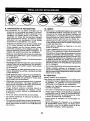
DANGER: This cutting machine is capable of amputating hands and feet and throwing
objects. Failure to observe the following safety instructions could result in serious injury
or death.
• Never direct discharged material toward
anyone. Avoid discharging
material
against awalf or obstruction. Material may
ricochet back toward the operator. Stop
the blade when crossing gravel surfaces.
• Do not operate machinewithoutthe entire
grass catcher, discharge chute, or other
safety devices in place and working.
* Slow down before turning.
• Never leave a running machine unattended. Always turn off blade, set parking brake, stop engine, and remove keys
before dismounting.
, Disengage blade when not mowing. Shut
off engine and wait for all parts to come
to a complete stop before cleaning the
machine, removing the grass catcher, or
unclogging the discharge chute.
° Operate machine only in daylight or good
artificial light.
, Do not operate the machine while under
the influence of alcohol or drugs.
• Watch for traffic when operating near or
crossing roadways.
, Use extra care when loading or unloading
the machine into a trailer or truck.
- Always wear eye protection when operating machine.
- Data indicates that operators, age 60
years and above, are involved in a large
percentage of riding mower-related injuries. These operators should evaluate
their ability to operate the riding mower
safely enough to protect themselves and
others from serious injury.
- Keep machine free of grass, leaves or
other debris build-up which can touch hot
exhaust / engine parts and burn. Do not
allow the mower deck to plow reaves or
other debris which can cause build-up to
occur. Clean any oil or fuel spillage before
operating or storing the machine. Allow
machine to cool before storage.
_IbWARNING:
In order to prevent accidental starting when setting up,transporting,
adjusting or making repairs, always disconnect spark plug wire and place wire where
it cannot contact spark plug.
_IbWARNING:
Do not coast down a hill
in neutral, you may lose control of the riding mower.
WARNING: Engine exhaust, some of its
constituents, and certain vehicle components
contain or emit chemicals known to the State
of Californiato cause cancer andbirth defects
or other reproductive harm.
_WARNING:This
unit is not intended
for the use of wheel weights. Only use
attachments designed specifically for this
riding mower.
_WARNING:
Battery posts, terminals
and related accessories contain lead and
lead compounds, chemicals known to the
State of California to cause cancer and birth
defects or other reproductive harm. Wash
hands after handling.
I. GENERAL OPERATION
- Read, understand, and follow all instructions on the machine and in the manual
before starting.
* Do not put hands or feet near rotating parts
or under the machine. Keep clear of the
discharge opening at all times.
- Only allow responsible adults, who are
familiar with the instructions, to operate
the machine.
, Clearthe area of objects such as rocks,
toys, wire, etc., which could be picked up
and thrown by the blade.
• Be sure the area is clear of bystanders
before operating. Stop machine if anyone
enters the area.
, Never carry passengers.
, Do not mow in reverse unless absolutely
necessary. Always look down and behind
before and while backing.
3
Ii. SLOPE OPERATION
Slopes are a major factor related to loss of
control and tip-over accidents, which can
result in severe injury or death. Operation
on all slopes requires extra caution. If you
cannot back up the slope or ifyoufeel uneasy
on it, do not mow it.
• Mow up and down slopes (15° Max), not
across.
• Watch for holes, ruts, bumps, rocks, or
other hidden objects. Uneventerrain could
overturn the machine. Tall grass can hide
obstacles.
• Choose a low ground speed so that you
will not have to stop or shift while on the
slope.
° Do not mow on wet grass. Tires may lose
traction,
° Always keep the machine in gear when
going down slopes. Do not shift to neutral
and coast downhill.
• If machine stops while going uphill,
disengage blade, shift into reverse and
back down slowly.
• Avoid starting, stopping, or turning on a
slope. Ifthetires]osetraction,
disengage
the blade and proceed s]owlystraight down
the slope.
• Keep all movementon the slopes slow and
gradual. Do not make sudden changes
in speed or direction, which could cause
the machine to roll over.
• Use extra care while operating machine
with grass catchers or other attachments;
they can affect the stability of the machine,
• Do no use on steep slopes,
- Do not try to stabilize the machine by
putting your foot on the ground.
• Do not mow near drop-offs, ditches, or
embankments. The machine could suddenly roll over if a wheel is over the edge
or if the edge caves in.
III. CHILDREN
Tragic accidents can occur if the operator
is not alert to the presence of children.
Children are often attracted to the machine
and the mowing activity. Never assume
that children will remain where you last
saw them.
• Keep children outofthe mowing areaand
in the watchful care of a responsible adult
other than the operator.
• Be alert and turn machine off if a child
enters the area.
• Before and while backing, look behind and
down for small children.
• Never carry children, even with the blade
shutoff. They mayfall offand be seriously
injured or interfere with safe machine
operation. Children who have been given
rides in the past may suddenly appear in
the mowing area for another ride and be
run over or backed over by the machine.
• Never allow children to operate the machine.
• Use extra care when approaching blind
corners, shrubs, trees, or other objects
that may block your view of a child.
IV, SERVICE
SAFE HANDLING OF GASOLINE
To avoid personal injury or property damage, use extreme care in handling gasoline.
Gasoline is extremely flammable and the
vapors are explosive.
• Extinguish all cigarettes, cigars, pipes,
and other sources of ignition.
• Use only approved gasoline container.
• Never remove gas cap or add fuel with
the engine running. Allow engine to cool
before refueling.
• Never fuel the machine indoors.
o Never storethe machine or fuel container
where there is an open flame, spark, or
piJot light such as on a water heater or
other appliances.
4
• Never fill containers inside a vehicle or
on a truck or trailer bed with plastic liner.
Always place containers on the ground
away from your vehicle when fitling.
- Removegas-poweredequipmentfromthe
truck or trailer and refuel it on the ground.
If this is not possible, then refuel such
equipment with a portable container, rather
than from a gasoline dispenser nozzle.
• Keep the nozzle in contact with the rim
of the fuel tank or container opening at
all times until fueling is complete. Do not
use a nozzle lock-open device.
• Iffuel is spitled on clothing, change clothing
immediately.
° Never overfill fuel tank, Replace gas cap
and tighten securely.
GENERAL SERVICE
- Never operate machine in a closed area.
• Keep all nuts and bolts tight to be sure the
equipment is in safe working condition.
- Never tamper with safety devices, Check
their proper operation regularly.
• Keep machine free of grass, leaves, or
other debris build-up. Clean oilorfuelspillage and remove any fuel-soaked debris.
Allow machine to cool before storing.
If you strike a foreign object, stop and
inspectthe machine. Repair, if necessary,
before restarting.
• Never make any adjustments or repairs
with the engine running.
• Check grass catcher components and the
discharge chute frequently and replace
with manufacturer's recommended parts,
when necessary.
• Mower blade is sharp, Wrap the blade or
wear gloves, and use extra caution when
servicing them,
• Check brake operation frequently. Adjust
and service as required.
• Maintain or replace safety and instruction
labels, as necessary.
, Be sure the area is clear of bystanders
beforeoperating. Stop machine ifanyone
enters the area.
• Never carry passengers.
• Do not mow in reverse unless absolutely
necessary. Always look down and behind
before and while backing.
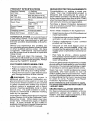
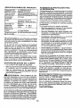
PRODUCT SPECIFICATIONS
[GasolineCapacity 1.5 Gallons
!andType:
UnleadedRegular
Oil Type
(API SG-SL):
Oil Capacity:
SAE 30 (Above 32°F)
SAE 5W30 (Below32°F)
48 Oz.
Spark Plug:
ChampionRC12YC
(Gap: .030")
GroundSpeed
(Mph):
Forward:
Reverse:
ChargingSystem:
BladeBolt Torque:
3 Amps @ Battery
45-55 Ft. Lbs.
0- 4
0- 2
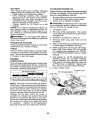
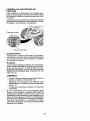
CONGRATULATIONS on your purchase of
a new riding mower, It has been designed,
engineered and manufactured to give you
the best possible dependability and performance.
Should you experience any problem you
cannot easily remedy, please contact a Sears
or other qualified service center. We have
competent, well-trained representatives
and the proper tools to service or repair this
riding mower.
Please read and retain this manual. The
instructions will enable you to assemble and
maintain your riding mower properly. Always
observe the "SAFETY RULES".
CUSTOMER
RESPONSIBILITIES
• Read and observe
the safety ruies.
• Follow a regular schedule in maintaining,
caring for and using your riding mower.
• Follewthe instructions under Maintenance
and Storage sections of this manual.
_,WARNING:
This
riding
mower
is
equipped with an internal combustion
engine and should not be used on or near any
unimproved forest-covered,
brush-covered
or grass-covered
land unless the engine's
exhaust system is equipped with a spark
arrester meeting applicable local or state
taws (ff any). If a spark arrester is used, it
should be maintained
in effective working
order by the operator.
lnthe state of Californiathe
above is required
by law (Section 4442 of the California Public
Resources Code). Other states may have
similar laws. Federal laws apply on federat
lands. A spark arrester for the muffler is
available through your nearest Sears service
center (See REPAIR PARTS manual).
REPAIR PROTECTIONAGREEMENTS
Congratulations on making a smart purchase. Your new Craftsman® product is
designed and manufactured for years of
dependable operation. But like all products,
it may require repair from timeto time. That's
when having a Repair Protection Agreement
can save you money and aggravation.
Purchase a Repair Protection Agreement
now and protect yourself from unexpected
hassle and expense.
Here's what's included in the Agreement:
,
Expert service by our 12,000 professional
repair specialists.
•
Unlimitedserviceand nochargefor parts
and labor on all covered repairs.
•
Product replacement if your covered
product can't be fixed.
•
Discount of t0% from regular price of
service and service-related parts not
covered bythe agreement; also, 10% off
regular price of preventive maintenance
check.
•
Fast help by phone - phone support
from a Sears representative on products
requiring in-home repair,plus convenient
repair scheduling.
Onceyou purchasethe Agreement, asimple
phone call is all that it takes for you to schedule service. Youcan call anytime dayor night,
or schedute a service appointment online.
Sears has over 12,000 professional repair
specialists, who have access to over 4.5
million quality parts and accessories. That's
the kind of professionalism you can count on
to help prolong the life of your new purchase
for years to come. Purchase your Repair
Protection Agreement today[
Some limitations and exclusions apply.
For prices and additional information call
1-800-827-6655.
SEARS INSTALLATION
SERVICE
For Sears professional installation of home
appliances, garage door openers, water
heaters, and other major home items, inthe
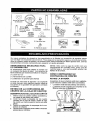
U.S.A. call 1-800-4-MY-HOME®
=
Steedng Wheel
Insert
Steedng
(1) 5t16-18
Hex Bolt
Shaft
(1) Front
Bumper
x 4
Stee_ng
Extension
(t) Rear Bumper
Wheel
(1) Lockwasher
j_
Steedng
I
Steering
Boot
@
Wheel
Adapter
Steedng
(4)Screw
Shaft Cover
#10 x 0,200
(1) Large Flat
(1) Shroud
Washer
(1) Cup Washer
(2)Key
Slope Sheet
Seat
(I) Knob
Your new riding mower has been assembled at the factorywith the exception ofthose parts
left unassembled for shipping purposes. To ensure safe and proper operation of your riding
mower all parts and hardware you assemble must be tightened securely. Use the correct
tools as necessary to ensure proper tightness.
TOOLS REQUIRED FOR ASSEMBLY
NOTE: Only cut carton with a short blade
utility knife, a long blade or saw can puncture
A socket wrench set will make assembly
easier. Standard wrench sizes you need tires on unit.
are listed below.
HOW TO SET UP YOUR RIDING
(1) 1/2" wrench
(1) Tire pressure gauge
MOWER
(1) Utility knife
CHECK BA'I-rERY
Ensure battery is securelyfastened, andthat
all wiresare securely connected,
° Battery is located under the seat,
• Battery has been fully charged from the
factory, before installation.
When right or left hand is mentioned in
this manual, it means when you are in the
operating position (seated behind the steering wheel).
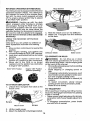
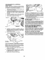
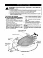
TO REMOVE
CARTON
RIDING MOWER FROM
UNPACK CARTON
1. Remove all accessible loose parts and
parts boxes from carton.
2. Cut along dotted lines on all four panels
of carton. Remove end panels and lay
side panels flat.
3. Remove packing materials from riding
mower.
4. Check for any additional loose parts or
cartons and remove.
Seat
7
artery
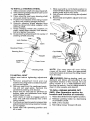
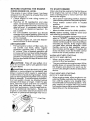
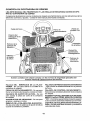
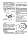
TO INSTALL STEERING WHEEL
1. Slide extension shaft onto steering shaft.
2. Slide steering shaft protective foam cover
over steering shaft.
3. Place steering boot over steering shaft
and push down to secure.
4. Position fr0nt wheels ofthe riding mower
so they are pointing straight forward.
5. Remove steering wheel adapter from
steering wheel and slide adapter onto
steering shaft,
7. Press steering wheel into position on
shaft, install large washer, lock washer,
bolt and tighten securely.
8. Snap steering wheel insert into center of
steering wheel securely.
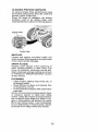
7. Slide seat until a comfortable position is
reached whichallows you to pressclutch/
brake pedal all the way down.
8. Get off seat without moving its adjusted
position.
9. Raise seat and tighten adjustment knob
securely.
Seat Pan
Pads
Cup Washer
Steering Boot_.....
Adjustment _'_\
Extension
Shaft _
FoamCover
f
g Shaft
TO INSTALL SEAT
Adjust seat before tightening adjustment
knob.
t. Remove adjustment knob and cup
washer securing seat to cardboard packing and set aside.
2, Remove seat from the cardboard packing and set seat aside, Remove the
cardboard packing and discard.
3. Place seat on seat pan so all three (3)
bottom pads are positioned over large
slotted holes in pan.
4. Push down on seat to engage pads in
slots and pull seat towards rear of the
riding mower,
5. Pivot seat andpanforward and assemble
adjustment knob and cup washer loosely.
Do not tighten.
6. Lower seat into operating position and
sit in seat,
NOTE: You may now rolt your riding
mower off the skid. Follow the appropriate
instruction below to remove the riding mower
from the skid.
WARNING: Before starting, read, understand and fo_low all instructionsin the
Operation section of this manual. Be sure
riding mower is in a well-ventilated area.
Be sure the area in front of riding mower is
clear of other people and objects.
TO ROLL RIDING MOWER OFF
SKID (See Operation section for
location and function of controls)
1. Raise deck liftleverto itshighest position.
2. Release parking brake by depressing
clutch/brake pedal.
3. Shift unit to neutral.
4. Roll riding mower forward off skid.
•
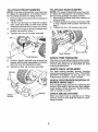
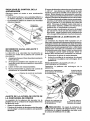
TO ATTACH REAR BUMPER
NOTE: For ease of assembly,you may wisl
to obtain the assistance of another person
for mountingbumper to riding mower.
1. Remove (4) screws from rear chassisof
riding mower,
2. Position bumper as shownandassemble
to rear chassis with screws removed in
step 1.
3, Tighten the four (4) screws securely,
TO ATTACH FRONT BUMPER
NOTE: For ease of assembly, you may wish
to obtain the assistance of another person
for mounting bumper to riding mower.
1. Remove (2) screws from front chassis of
riding mower,
2. Tilt the front bumper so that the bumper
tabs catch the slots on the front of the
chassis and lower the bumper into place.
3, Attach the bumper to front of chassis with
screws removed in step 1.
4. Tighten the two (2) screws securely.
Rear Bumper
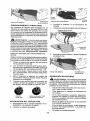
CHECK TIRE PRESSURE
The tires on your ridingmower were overinflated at the factory for shipping purposes.
Correct tire pressure is important for best
cuttingperformance.
Screw
5, Position plastic shroud over bumper as
shown and loosely assmeble to bumper
with the four (4) supplied screws,
6, Tighten ati four (4) screws securely.
CHECK DECK LEVELNESS
For best cutting results, mower housing
shouldbe properlyleveled, See "TO LEVEL
MOWER HOUSING" in the Service and
Adjustments section of this manual.
Screws
CHECK FOR PROPER POSITON OF
MOWER DRWE BELT
See the figure that is shownfor replacingthe
mower drive belt in the service and adjustment section ofthis manual, Verify that the
belt is routed correctly.
CHECK BRAKE SYSTEM
After you learn how to operate your riding
mower, check to see that the brake is operating properly.
Plasti_
Shroud
9
t_CHECKLIST
Before you operate your new riding mower,
we wish to assure that you receive the best
performance and satisfaction from this Quaiit,/Product.
Please review the following checklist:
J
All assembly instructions have been
completed.
,/ No remaining loose parts in carton.
,/ Battery is properly connected.
,I Seat is adiusted comfortably and tightened securely.
,/ All tires are properly inflated, (For shipping purposes, the tires were overinflated
at the factory.)
,/ Be sure mower deck is properly leveled
side-to-side/front-to-rear far best cutting
results. Fires must be properly inflated
for leve_ing.)
€" Check mower belt. Be sure it is routed
properly around pulleys and inside all belt
keepers,
v" Check wiring. See that all connections
are still secure and wires are properly
clamped.
While learning how to use your riding mower,
pay extra attention to the following important
iterr_s:
7" Engine oil is at proper level.
J Fuel tank is filled with fresh, clean, regutar
unleaded gasoline.
J Become familiar with all controls, their
location and function. Operate them
before you start the engine.
,/ Be sure brake system is in safe operating
condition.
,/
Be sure Operator Presence System and
Reverse Operation System (ROS) are
working properly (Seethe Operation and
Maintenance sections in this manual,)
10
These symbols may appear on your riding mower or in literature supplied with the product.
Learn
and understand
R
their meaning.
N
REVERSE
NEUTRAL
H
HIGH
L
LOW
CHOKE
FAST
SLOW
|GNITION
ENGINEOFF
REVERSE ENGINEON
OPERATION
SYSTEM(ROS)
FUEL
OIL PRESSURE
ATTACHMENT
CLUTCH
ENGAGED
BATTERY
ATTACHMENT
CLUTCH
DISENGAGED
ENGINESTART
REVERSE
PARKINGBRAKE
FORWARD
DANGER,
KEEP HANDS
AND FEET AWAY
MOWER
KEEP
AREA
SWITCH
PARKING
aRAKE PARKINGBRAKE
LOCKED
UNLOCKED
HEIGHT
CLEAR
(SEE SAFETY
MOWER
SLOPE
RULES
LIFT
HAZARDS
SECTION)
DANGER
will result indicates
In death aorhazard
seriouswhich,
injury.it not avoided,
BRAKE/CLUTCH
PEDAL
WARNING
hazard
which,
if not avoided,
could
resultindicates
in deatha or
serious
injury.
&
Failure to follow instructions
could result in serious injury or
death. The safety alert symbol
is used to identify safety information about hazards which can
result in death, serious injury
and/or property damage,
CAUTION
indicates
a hazard
which, if
not avoided,
might result
in minor
or moderate
injury.
CAUTION awhen
usedthat
without
alertin symbol,
indicates
situation
could the
result
damage
to the tractor and/or engine.
HOT SURFACES indicates a hazard which,
if not avoided, could result in death, serious injury
and/or property damage.
FIRE indicates a hazard which, if not avoided,
could result In death, serious Injury and/or
property damage.
11
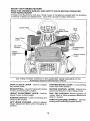
KNOW YOUR RIDING MOWER
READ THIS OWNER'S MANUAL AND SAFETY RULES BEFORE OPERATING
YOUR RIDING MOWER
Compare the illustrations with your riding mower to familiarize yourself with the locations
of various controls and adjustments. Save this manual for future reference.
Brake Pedal
Parking
Lever
Deck Clutch
Lever
IgniUon
Switch
Lift Lever
Throttle/Choke
Height
Adjl
Lever
Motion Control
Our riding mowers conform to the applicable safety standards of the
American National Standards Institute.
PARKING BRAKE LEVER - Locks parking
brake into brake position.
MOTION CONTROL LEVER - Selects the
speed and direction of the riding mower.
DECK CLUTCH LEVER - Used to engage
the mower blade.
BRAKE PEDAL- Used for braking the riding
mower and starting the engine.
HEIGHT ADJUSTMENT
LEVER
adjust mower cutting height.
- Used to
IGNITION SWITCH - Used for starting
stopping the engine.
ROS "ON" POSITION -Allows operation of
mower deck or other powered attachment
while in reverse.
and
LIFT LEVER PLUNGER - Used to release
height adjustment lever when changing its
position.
THROTTLE/CHOKE CONTROL- Used for
starting and controlling engine speed.
12
The operation of any riding mower can result in foreign objects thrown
into the eyes, which can result in severe eye damage, Always wear
safety glasses or eye shields while operating your riding mower or
performing any adjustments or repairs. We recommend a wide vision
safety mask over spectacles or standard safety glasses.
GROUND DRIVE • Tostop ground drive, depress brake pedal
all the way down.
. Move motion control leverto neutralposition.
ControlLever
HOW TO USE YOUR RIDING
MOWER
TO SET PARKING BRAKE
Your ridingmoweris equippedwithan operator presence sensing switch. When engine
is running, any attempt by the operator to
leave the seat withoutfirst setting the parking
brake will shut off the engine.
1. Depress brake pedal all the way down
and hold.
2. Pull parking brake lever up and hold,
release pressure from brake pedal, then
release parking brake lever, Pedal should
remain in brake position. Ensure parking
brake will hold mower secure.
ENGINE o Move throttle control between haft and full
speed (fast) position.
NOTE: Failure to move throttle control between half and full speed (fast) position, before stopping, may cause engineto"backfire".
STOPPING
MOWER BLADE • To stop mower blade, move deck clutch
lever to disengaged position.
(_I_)
"_
Deck Clutch
Control
"Engaged ....
(!'_1))eck
Clutch
Control
Disengaged"
• Turn ignition key to "STOP" position and
remove key. Always remove key when
leaving riding mower to prevent unauthorized use.
IMPORTANT: Leaving the ignitionswitch in
any position other than "STOP" witl cause
the battery to discharge and go dead.
NOTE: Undercertain conditions when riding
mower is standing idle with the engine running, hot engine exhaust gases may cause
"browning" of grass. To eliminate this possibility, always stop engine when stopping
riding mower on grass areas.
CAUTION: Always stop riding mower
completely, as described above, before
leaving the operator's position.
13
TO USE THROTTLE CONTROL
Always operate engine at full speed (fast).
• Operating engine at less than full speed
(fast)reduces engine's operating efficiency.
- Full speed (fast) offers the best mower
performance.
Throttle
\
TO MOVE FORWARD
AND BACKWARD
The direction and speed of movement
controlled by the motion control lever.
t.
Ensure the parking
2,
Start riding mower with motion
lever in neutral (N) position.
3.
Release
4,
Slowly
desired
parking
is
brake is applied.
control
brake,
move motion
position,
control
Control
lever
• The average lawn should be cut to approximately 2-1/2" during the cool season
and to over 3" during hot months. For
healthier and better looking lawns, mow
often and after moderate growth,
• For best cutting performance, grass over
6" in heightshould be mowedtwice. Make
the first cut relatively high; the second to
desired height.
TO OPERATE MOWER
Your riding mower is equipped with an
operator presence sensing switch, Any
attempt by the operator to leave the seat
with the engine running and the deck clutch
engaged will shut off the engine, You must
remain fully and centrally positioned in the
seat to prevent the engine from hesitating or
cutting off when operating your equipment
on rough, rolling terrain or hills.
1. Select desired height of cut,
2, Start mower blade by engaging deck
clutch lever.
TO STOP MOWER BLADE Disengage deck clutch lever.
DeckClutchLever
MowerHeight
"Disengaged"Position
AdjustmentHigh
Position
to
Lever
\
\
\
\
Deck Clutch Lever
"Engaged" Position
TO ADJUST MOWER CUTTING HEIGHT
The position of the mower height deck lift
lever determines the cutting height,
. Grasp lift lever,
• Press lift lever plunger with thumb and
move lever to desired position.
The cutting height range is approximately
1-I/2to 4". The heights are measured from
the ground to the blade tip with the engine
not running. These heights are approximate
and may vary depending upon soil conditions, height of grass and types of grass
being mowed.
Mower
Height Adjustment
Low Position
_Jl, CAUTION: Do not operate the mower
without either the entire grass catcher, on
mowers so equipped, mulch cover, or the
deflector shield in place.
Deflector Shield
14
Mulch Cover
REVERSE OPERATION SYSTEM (ROS)
Yourdding mowerisequippedwitha Reverse
Operation System (ROS). Any attempt by
the operator to travel in the reverse direction with the deck clutch engaged will shut
off the engine unless ignition key is placed
in the ROS "ON" position.
_lkWARNING: Backing up with the deck
clutch engaged while mowing is strong[y
discouraged, Turning the ROS "ON", to allow reverse operation with the deck clutch
engaged, should only be done when the
operator decides it isnecessaryto reposition
the machine with the attachment engaged.
Do not mow in reverse unless absolutely
necessary.
USING THE REVERSE OPERATION
SYSTEM Only use if you are certain no children or
other bystanders will enter the mowing
area,
1. Move motion control lever to neutral (N)
position.
2. With engine running, turn ignition key
counterclockwise to ROS "ON" position.
3. Look down and behind before and while
backing.
4. Slowly move motion control lever to
reverse (R) position to start movement.
5. When use of the ROS is no longer
needed, turn the ignition key clockwise
to engine "ON" position.
ROS "ON" Position
Hinge Bracket
Shield
4. Rest the mulch cover on the deflector.
5. Attach the 1 bungee from the deflector
to the deck.
Deflector Shield
TO OPERATE ON HILLS
_WARNING:
Do not drive up or down
hills with slopes greater than 15° and do not
drive across any slope. Use the slope guide
at the back of this manual.
• Choosetheslowestspeed beforestarting
up or down hills.
• Avoid stopping or changing speed on
hills,
• If stopping is absolutely necessary, push
clutch/brake pedal quickly to brake position and engage parking brake.
• Move motion control lever to neutral (N)
position.
• To restart movement, slowly release
parking brake and clutch/brake pedal.
• Make all turns slowly.
Engine "ON" Position
(Normal Operating)
TO ATTACH DEFLECTOR
1. Unhook the 2 bungees from deck to the
mulch cover.
TO TRANSPORT
When pushing or towing yourridingmower,
besure to disengagetransmission by placing
shifter in neutral,
o Raise mower height adjustment to its highest position with mower height adjustment
lever.
o To reengage transmission, press brake
and shift out of neutral,
Bungee
Mulch Cover
Cover
Bungee
2, Liftthe mulch cover.
3. Attach the deflector to the hinge bracket.
15
BEFORE STARTING THE ENGINE
CHECK ENGINE OIL LEVEL
The engine in your riding mower has been
shipped, from the factory, already filled with
summer weight oil.
1. Check engine oil with riding mower on
level ground.
2. Remove oil fill cap/dipstick and wipe
clean, reinsert the dipstick and screw cap
tight, wait for a few seconds, remove and
read oil level. If necessary, add oil until
"FULL' mark on dipstick is reached. Do
not overfill.
• For cold weather operation you should
change oil for easier starting (See the oil
viscosity chart inthe Maintenance section
of this manual).
• To change engine oil, see the Maintenance section in this manual,
ADD GASOLINE
• Fill fuel tank to bottom offiller neck. Do
not overfill. Use fresh, clean, regular
unleaded gasoline with a minimum of
87 octane. (Use of leaded gasoline will
increase carbon and lead oxide deposits
and reduce valve life). Do not mix oil with
gasoline. Purchase fuel inquantities that
can be used within 30 days to assure fuel
freshness.
_, CAUTION: Wipe off any spilled oil or
fuel. Do not store, spill or use gasoline near
an open flame.
CAUTION: Alcohol blendedfuels (called
gasohol or using ethanol or methanol) can
attract moisture which leads to separation
and formation ofacids during storage. Acidic
gas can damage the fuel system of an engine
while in storage. To avoid engine problems,
the fuel system should be emptied before
storage of 30 days or longer. Drain the gas
tank, start the engine and let it run until the
fuel lines and carburetor are empty. Use
fresh fuel next season. See Storage Instructions for additional information. Never use
engine or carburetor cleaner products in the
fuel tank or permanent damage may occur.
TO START ENGINE
When starting the engine for the first time or
if the engine has run out of fuel, it will take
extra cranking time to move fuel from the
tank to the engine.
* Siton seatin operating position, depress
clutch/brake pedal and set parking brake.
- Place motion control lever in neutral
position.
• Move deck clutch lever to "DISENGAGED" position.
Move throttle control to choke positionl
NOTE: Before starting, read the warm and
cold starting procedures below.
° Insert key intoignition andturn keyclockwise to "START" position and release
key as soon as engine starts. Do not run
starter continuously for more than fifteen
seconds per minute. If the engine does
not start after several attempts, move
throttle control to fast position, wait a
few minutes and try again. If engine still
does not start, move the throttle control
back to the choke position and retry.
WARM WEATHER STARTING
(50°F/10°C AND ABOVE)
• When engine starts, move the throttle
control to the fast position.
, The ground drive can now be used. Ifthe
engine does not accept the load, restart
the engine and at]ow it to warm up for
one minute usingthechoke as described
above.
COLD WEATHER STARTING
(50°F/10°0 AND BELOW)
• When engine starts, allow engine to run
with the throttle control inthe choke position until the engine runs roughly, then
move throttle control tofast position. This
may require an engine warm-up period
from several seconds to several minutes,
depending on the temperature.
Cap
16
MOWING TIPS
- Mower should be properlyleveled for best
mowing performance. See "TO LEVEL
MOWER HOUSING" in the Service and
Adjustments section of this manual.
• The left hand side of mower should be
used for trimming.
• Drive so that clippings are discharged
onto the area that has already been cut.
Have the cut area to the right of the riding
mower. This will result in a more even
distribution of clippings and more uniform
cutting.
1I
,1_,,
•
°
•
•
•
When mowing large areas,startbyturning
tothe right sothat clippings wil]discharge
away from shrubs, fences, driveways,
etc. After one ortwo rounds, mow in the
opposite direction making [eft hand turns
until finished.
tf grass is extremely tall, it should be
mowed twice to reduce load and possible
fire hazard from dried clippings. Make
first cut relatively high; the second to the
desired height.
Do not mow grass when it is wet. Wet
grass will plug mower and leave undesirable clumps. Allow grass to dry before
mowing.
Regulate ground speed byselecting alow
enough gear to give the mower cutting
performance as well as the quality of cut
desired.
When operating attachments, select a
ground speed that will suit the terrain and
give best performance of the attachment
being used.
I7
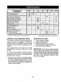
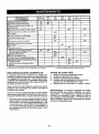
MAINTENANCE
R
D I Check Operator, Presence & ROe Systems
G
(_
for Loose
Check/Replace
Clean
BaKery
Lubricate
Friction
Surfaces
Check
Mower
L_velnes5
R;
Check
V-Beff
SEASON
STORAGE
t/
...........
i/
v"
v'
v'0
i/
,i,illllll iii
=/
Check En,gine Oil Level
Engine
....Ev_.Y F-E_o.E
iv"
V_3
and Spindles
Axles
EVERY
100
HOURS
I
v"
Mower
B|ad,e
and Terminal5
Clean
Change
i/
EVERY
51)
HOURS
.IIHI Illl
Fast,net5
E
E
e
HOURS
v"
v"
Check
BrakePressure
Qperatian
Check Tire
Check
EVERY
25
HOURe
F.VERY
EACH
USE
SCHEDULE
If
,
tf
Oil
....
N cIeanA_r Filter
G
Clean
Inspe'ct
Air
v'2
Screen
Muff|edSpark
i/
Arc'ester
,=
Clean
Engine
Cooling
Replace
Spark
Replace
Afr Filter
GENERAL
Fins
v' ...................
v"
Plug
=/,
Paper Cartridge
RECOMMENDATIONS
BEFORE EACH USE
1. Check engine oil level.
2. Check brake operation.
3. Check tire pressure.
4. Check operator presence and
ROS systems for proper operation.
5. Check for loose fasteners.
The warranty on this riding mower does not
cover items that have been subjected to
operator abuse or negligence.
To receive
full value from the warranty, operator must
maintain riding mower as instructed in this
manual.
Some adjustments will need to be made
periodically to properly maintain your riding
mower,
IMPORTANT: Do not oil or grease the pivot
points which have special nylon bearings.
Viscous lubricants will attract dust and dirt
that willshorten the life of the self-lubricating
bearings, lfyou feel they must be lubricated,
use only a dry, powdered graphite type
lubricant sparingly.
At least once a season, check to see if
you should make any of the adjustments
described in the Service and Adjustments
section of this manual.
- At least once a year you should replace
the spark plug, clean or replace air filter,
and check blade and belt for wear. A new
spark plug and clean airfilter assure proper
air-fuel mixture and help your engine run
better and last longer.
18
RIDING MOWER
Always observe safetyruleswhen performing
any maintenance.
BRAKE OPERATION
If riding mower requires more than four (4)
feet to stop at highest speed in highest gear
on a level, dry concrete or paved surface,
then brake must be serviced at your nearest
authorized service center.
TIRES
- Maintain tire pressure at 12 PSI.
o Keep tires free of gasoline, oil, or insect
control chemicals which can harm rubber.
• Avoid stumps, stones, deep ruts, sharp
objects and other hazards that may cause
tire damage.
NOTE: To seal tire punctures and prevent
flat tires due to slow leaks, tire sealant may
be purchased from your local parts dealer.
Tire sealant also prevents tire dry rot and
corrosion.
AXLE AND SPINDLES
• Front wheelaxles and front spindles should
be properly lubricated.
• Wheel axles and spindles should be
lubricated with grease.
CHECK REVERSE OPERATION (ROS)
SYSTEM
- Whenthe engine isrunning with the ignition
switch inthe engine "ON" positionand the
deck clutch lever engaged, any attempt by
the operator to shift into reverse should
shut off the engine.
• When theengine is running withthe ignition
switch in the ROS "ON" position and the
deck clutch lever engaged, anyattempt by
the operator to shift into reverse should
NOT shut off the engine.
ROS "ON"
Position
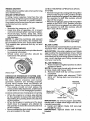
BLADE CARE
For best results mower blades must be sharp,
Replace worn, bent or damaged blades.
-&CAUTION: Use only a replacement blade
approved by the manufacturer of your riding
mower. Using a blade not approved by the
manufacturer of your riding mower is hazardous, could damage your riding mower and
void your warranty.
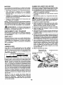
BLADE REMOVAL
!. Raise mower to highest position to allow
access to blade,
NOTE: Protect your hands with gloves and/
or wrap blade with heavy cloth,
2. Remove blade bolt by turning counterclockwise.
3. Install new blade with stamped "THIS
SIDE UP" facing deck and mandrel assembly.
Whe Sel
pinAxlde_.
OPERATOR PRESENCE SYSTEM AND
REVERSE OPERATION SYSTEM (ROS)
Be sure operator presence and reverse
operation systems are working properly.
If your riding mower does not function as
described, repair the problem immediately.
- The engine should not start unless the
brake pedalisfully depressed, andthe deck
clutch lever is in the disengaged position.
CHECK OPERATOR PRESENCE SYSTEM
- When the engine is running, any attempt
by the operator to leave the seat without
first setting the parking brake should shut
off the engine.
• When the engine is running and the deck
clutch Feveris engaged, any attempt by
the operator to leave the seat should shut
off the engine.
• Never operatethe deck clutch lever unless
you are seated in the seat.
Engine "ON" Position
(Normal Operating)
Mandrel
Assembly
(Special
.Star
Center Hole
IMPORTANT: To ensure proper assembly,
center hole in blade must align with star on
mandrel assembly.
4. Install and tighten blade bolt securely
(45-55 Ft. Lbs.).
IMPORTANT: Special blade bolt is heat
treated.
19
BATTERY
Your riding mower has a battery charging
system which is sufficient for normal use.
- Keep battery and connectors clean.
* Only recharge battery with charger
approved for a 12V 6 amp. hour battery.
• Charging with any other charger or an
automotive style charger can cause permanent damage to the battery.
* Charge battery for 24 hours for a full
charge.
NOTE: The original equipment battery on
your riding mower is maintenance free. Do
not attempt to open or remove caps or covers. Adding or checking level of electrolyte
is not necessary,
_WARNING:
Do not jump start battery.
Permanent damage to the battery or personal
injury may occur.
TRANSAXLE COOLING
Keep transaxle free from build-up of dirt and
chaff which can restrict cooling.
V-BELT
Check V-belt for deterioration and wear after
100 hours of operation and replace if necessary. The belt is not adjustable. Replace belt
ff it begins to slip from wear.
ENGINE
LUBRICATION
Only use high quality detergent oil rated with
API service classification SG-SL. Selectthe
oil's SAE viscosity grade according to your
expected operating temperature,
SAE V_SCOSITY
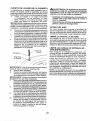
TO CHANGE ENGINE OIL
Determine temperature range expected
before oil change. All oil must meet API
service classification SG-SL.
• Be sure riding mower is on level surface.
• Oil will drain more freely when warm.
• Catch oil in a suitable container.
_IL CAUTION: If engine has been operated
for an extended period of time immediately
prior to draining oit, oil will be hot.
1. Lift engine cover.
2. Remove oi! fill cap/dipstick. Be careful
not to allow dirt to enter the engine when
changing oil.
3. Position a container to catch oil.
4. Remove drain plug and drain oil into
container.
5. Afteroil has drained completely, replace
oil drain plug and tighten securely.
6. Refill engine with oil through oil fill dipstick tube. Pour slowly. Do not overfill.
For approximate capacity see "PRODUCT SPECIFICATIONS" section of this
manual.
7. Use gauge on oil fill cap/dipstick for
checking level. For accurate reading,
tighten dipstick cap securely onto the
tube before removing dipstick. Keep oil
at "FULL' line on dipstick. Tighten cap
onto the tube securely when finished.
8. Lower engine cover.
Engine Cover
GRADES
Oil Fill Cap/Dipstick
Drain Plug
NOTE: Although multi-viscosity oils (5W30,
10W30 etc.) improve starting in cold weather,
the oils will result in increased oil consumption
when used above 32°E Check your engine
oiI level more frequently to avoid possible
engine damage from running low on oil.
Change the oil after every 25 hours of
operation or at least once a year if the riding
mower is not used for 25 hours in one year.
Check the crankcase oil level before starting
the engine and after each eight (8) hours
of operation.
Tighten oil fill cap/dipstick
securely each time you check the oil level.
20
\\
\
_/
//
DECK WASHOUT PORT
Your riding mower's deck is equipped with
a washout port on its surface as part of its
deck wash system. It should be utilized after each use.
1. Drive the riding mower to a level, clear
spot on your lawn, near enough to a
water spigot for your garden hose to
reach.
IMPORTANT: Make certain the riding
mower's discharge chuteis directed AWAY
from your house, garage, parked cars, etc.
Remove bagger chute or mulch cover ff
attached.
2. Make sure the attachment clutch control
is in the "DISENGAGED" position, set
the parking brake, and stop the engine,
3. Thread the nozzle adapter (packaged
with your riding mower's Operator's
Manual) onto the end of your garden
hose.
4. Pull back the lock collar of the nozzle
adapter and push the adapter onto the
deck washout port at the left end of the
mower deck, Release the lock collar to
lock the adapter on the nozzle.
Nozzle
_/Hose
Adapter_.._
Washout
8,
Move the riding mower's attachment
clutch control to the "DISENGAGED"
position. Turn the ignition key to the
STOP position to turn the tractor's
engine off. Turn the water off.
9. Pull back the lock collar of the nozzle
adapter to disconnect the adapter from
the nozzle washout port.
10. Move the riding mower to a dry area,
preferably a concrete or paved area.
Place the attachment clutch control in
the "ENGAGED" position to remove
excess water and to help dry before
putting the riding mower away.
_LWARNING:
A broken or missing
washout fitting could expose you or
others to thrown objects from contact
with the blade.
•
Replace broken or missing washoutfitting immediately, prior to using mower
again.
•
Plug any holes
and Iocknuts.
in mower
with
bolts
AIR FILTER
Your engine will not run properly using a
dirty air filter. Service air cleaner more often
under dusty conditions. See engine manual,
CLEAN AIR SCREEN
Air screen must be kept free ofdirt and chaff
to preventenginedamagefrom overheating.
Clean witha wire brushorcompressed airt0
remove dirt and stubborn dried gum fibers.
IMPORTANT: Tug hose ensuring connection is secure.
5. Turn the water on.
6. While sitting in the operator's position
on the riding mower, re-start the engine
and place the throttle lever in the Fast
"4_" position.
IMPORTANT: Recheck the area making
certain the area is clear.
7. Move the riding mower's attachment
clutch control to the "ENGAGED" position. Remain in the operator's position withthe cuttingdeckengaged until
the deck is cleaned.
21
CLEAN AIR INTAKE/COOLING AREAS
To ensure proper cooling, make sure the
grass screen, coolingfins, and other external surfaces of the engine are kept clean
at all times.
Every 100 hours of operation (more often
under extremely dusty, dirty conditions),
remove the blower housing and other cooling
shrouds. Cieanthe cooling fins and external
surfaces as necessary. Ensure the cooling
shrouds are reinstalled.
NOTE: Operating the engine with ablocked
grass screen, dirty or plugged cooling fins,
and/or cooling shrouds removed will cause
engine damage due to overheating,
CLEANING FRICTION SURFACES
To ensure proper drive performance keep
the friction surfaces free from dirt, chaff and
excess rubber at all times.
Every 25 hours of operation, the friction
surfaces need to be rubbed clean with
isopropyl alcohol or other non-filming cleaner.
Engine Plate
Friction Disc
MUFFLER
inspect and replace corroded muffler and
spark arrester (if equipped) as it could create
a fire hazard and/or damage.
SPARK PLUG(S)
Replace spark plug(s) at the beginning of
each mowing season or after every 100
hours of operation, whichever occurs first.
Spark plug type and gap setting are shown
in "PRODUCT SPECIFICATIONS" section
of this manual.
CLEANING
• Clean engine, battery, seat, finish, etc. of
all foreign matter,
• Keep finished surfaces and wheels free
of all gasoline, oil, etc.
• Protect painted surfaces with automotive
type wax.
We do not recommend using a garden hose
or pressure washer to clean your riding
mower unless the engine and transmission
are covered to keep water out. Water in engine or transmission wiil shorten the useful
life of your riding mower, Use compressed
air or a leaf blower to remove grass, leaves
and trash from riding mower and mower.
22
SERVICE ORTO
WARNING:
ADJUSTMENTS:
AVOID SERIOUS INJURY, BEFORE PERFORMING ANY
1. Depress clutch/brake pedal fully and set parking brake.
2. Place motion control lever in neutral (N) position.
3. Place deck clutch in "DISENGAGED" position.
4. Turn ignition key to "STOP" and remove key,
5, Ensure the blade and all moving parts have completely stopped.
6. Disconnect spark plug wire from spark plug and place wire where it cannot
come in contact with plug,
RIDING MOWER
TO REMOVE MOWER
1. Place deck clutch in "DISENGAGED"
position.
2. Move mower height adjustment lift lever
forward to lower mower to its lowest
position.
3, Remove mandrei cover.
4. Remove pins holding left and right front
mower suspension arms in place.
5. Remove bolt holding deck front to rear
leveling rod in place.
6. Remove pin holding deck lift link arm in
place.
7. Remove bolt holding deck side to side
leveling rod in place,
8, Remove belt from around pulleys.
9. Slide deckout from under side of mower.
TO INSTALL MOWER
Installin reverseorderfollowinginstructions
in "TO REMOVE MOWER" section.
Deck Leveling
Side to Side
Rod Bolt
Mandrel Cover
Front Leveling
Lift
Link Pin
Mower
Suspension
Arm Pin
23
TO LEVEL MOWER HOUSING
Adjust the mower while riding mower is
parked on level ground or driveway. Ensure
tires are properly inflated. If tires are over or
underinflated, you will not properly adjust
your mower.
SI DE-TO-SIDE ADJUSTMENT
• Raise mower to its highest position.
• Measure distance "A" from bottom edge
of mower to ground level at front corners
of mower,
Bottom Edgeof
Mower to Ground
BottomEdgeof
Mowerto Ground
t!! il ....... tl !tJ x'
• To raise the right side ofthe mower, tighten
lift link adjustment nut.
• To lower the rightsideofthe mower, loosen
lift link adjustment nut.
NOTE: Each full turn of adjustment nut will
change mower height about 3/16".
• Recheck measurements after adjusting.
Adjustment
FRONT-TO-BACK ADJUSTMENT
IMPORTANT: Deck must be level side-to
side.
Toobtain the best cutting results, the mower
housing should be adjusted so that the front
is approximately 1/8" to 1/2" lower than the
rear when the mower is in its highest position.
Check adjustment on right side of riding
mower. Measure distance"F" directly infront
and behind the mandrel at bottom edge of
mower housing as shown.
• To lower front of mower housing turn nuts
"G" and "H" clockwise.
• When distance "F" is 1/8" to 1/2" lower
at front than rear, tighten nut "H" against
trunnion on front link.
• To raise front of mower housing turn nuts
"G" and "H" counter clockwise.
• When distance "F" is 1/8" to 1/2" lower
at front than rear, tighten nut "H" against
trunnion on front link.
NOTE: Each full turn of "G" will change "F"
by approximately
about 3/8".
Nut
• Recheck
Turn nut left
"\'\_'_/_.
_-_"
side-to-side
Turnnut right
Nut
to raise mower . \-_\i__
_o iower mower
Trunnion
i
24
adjustment.
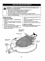
TO REPLACE MOWER BLADE DRIVE
BELT
TO ADJUST STEERING WHEEL
ALIGNMENT
Ifsteeringwheeicrossbars are not horizontal
(left to right) when wheels are positioned
straight forward, remove steering wheel
and reassemble per instructions in the
"INSTALL STEERING COLUMN" section
of this manual.
MOWER DRIVE BELT REMOVAL
I. Park riding mower on a level surface.
2. Set parking brake.
3, Lower mower to its lowest position,
4. Remove mandrelcoverfrem mowerdeck.
5. Remove rear engine plate from unit.
6. Remove rear belt keeper from unit.
7, Carefully roll belt over the top of the
mower blade mandrel,
TO REMOVE WHEEL FOR REPAIRS
FRONT WHEEL
1. Block up front axle securely.
2. Remove dust cover, retaining ring, and
washer to allow wheel removal.
3. Repair tire and reassemble.
4. Replace washer and retaining ring
securely in axle groove.
REAR WHEEL
1. Block up Rear axle securely.
2. Remove dustcover,retainingring,washer, and square key while pulling tire off.
3. Repair tire and reassemble.
4, Replacesquare keywhile putting tire back
on, then replace washer and retaining
ring securely in axle groove.
Ma _drel
8, Remove belt from idler pulleys,
9. Check idler pulleys to seethatthey rotate
freely,
10, Remove belt from rear drive pulley.
MOWER DRIVE BELT INSTALLATION
Install in reverse order following instructions in "MOWER DRIVE BELT REMOVAL"
section.
TO CHECK BRAKE
If riding mower requires more than four (4)
feet to stop at highest speed in highest gear
on a level, dry concrete or paved surface,
then brake must be serviced.
You may also check brake by:
1. Park riding mower on a level, dry concrete or paved surface, depress clutch/
brake pedal all theway down and engage
parking brake.
2. Place motion control lever in neutral
position.
The rear wheels must lock and skid when
you try to manually push the riding mower
forward. If the rear wheels rotate, then the
brake needs to be serviced. Contact a Sears
or other qualified service center,
Washer
Retaining [
Ring
Dust
Cover
/
SquareKey
(rear wheel only)
NOTE: To seal tire punctures and prevent
flat tires due to slow leaks, purchase and
use tire sealantfrom Sears. Tire sealant also
prevents tire dry rot and corrosion.
TO START ENGINE WITH A WEAK
BATTERY
_I_CAUTION: Lead-acid batteries generate explosive gases. Keep sparks, flame
and smokingmaterials away from batteries.
Always wear eye protection when around
batteries.
If your battery is too weak to startthe engine,
_tshould be recharged. (See "BATTERY" in
the Maintenance section of this manual).
25
REPLACING BATTERY
_t, WARNING: Do not short battery terminals by allowing awrench or any other object
to contact both terminals at the same time.
Before connecting battery, remove metal
bracelets, wristwatch bands, rings, etc.
Positive terminal must be connected first to
prevent sparking from accidental grounding.
t. Lift seat pan to raised position.
2. Remove terminal cover.
3. Disconnect BLACK battery cable then
RED battery cabie, battery strap and
carefully remove battery from riding
mower.
4. Install new battery with terminals insame
position as old battery,
5. Reinstall terminal cover.
6. First connect RED battery cable to
positive (+) battery terminal with bolt and
nut as shown. Tighten securely,
7, Connect BLACK grounding
cable
to negative (_) battery terminal with
remaining bolt and nut, Tighten securely
8. Lower seat 3an.
Nut.
Cable
[_-_'.
_t
_
Nut
uaoie
INTERLOCKS AND RELAYS
Loose or damaged wiring may cause your
riding mower to run poorly, stop running, or
prevent it from starting.
• Check wiring. Ensure all wiring and connectors are secure,
ENGINE
Your carburetor is net adjustable. If your
engine does not operate properly due to
suspected carburetor problems, take your
riding mower to a qualified service center
for repair and/or adjustment.
26
Immediately
prepare
yourriding
mower
for • Empty the fuel tank by starting the engine
storage
attheendoftheseason
Orifthe and letting it run until the fuel lines and
ridingmower
wiltnotbeusedfor30days carburetor are empty.
or more.
• Never use engine or carburetor cleaner
_kWARNING:
Neverstorethe
riding
mower products in the fuel tank or permanent
withgasoline
inthetankinside
a building damage may occur,
where
fumesmayreach
anopenflame
or • Use fresh fuet next season.
spark.
Allowtheengine
tocootbefore
stor- NOTE: Fuel stabilizer is an acceptable alingin any enclosure.
ternative in minimizing the formation of fuel
MOWER
Remove deckfrom mower for winter storage.
When mower is to be stored for a period of
time, clean it thoroughly, remove all dirt,
grease, leaves, etc. Store in aclean, dryarea.
I. Clean entire riding mower (See"CLEANING" in the Maintenance section of this
manual).
2. Inspect and replace belt, if necessary
(See belt replacement instructionsinthe
Service and Adjustments section of this
manual),
3. Lubricate as shown in the Maintenance
section of this manual,
4. Be sure that all nuts, bolts and screws
are securely fastened. Inspect moving
parts for damage, breakage and wear.
Replace if necessary.
5, Touch up all rusted or chipped paint
surfaces; sand lightly before painting.
BATTERY
•FuIly charge
• If battery is
for storage,
on concrete
gum deposits during storage. Add stabilizer
to gasoline in fuel tank or storage container.
Always follow the mix ratio found on stabilizer
container. Run engine at least 10 minutes
after adding stabilizer to allow the stabilizer to
reach the carburetor. Do not empty the gas
tank and carburetor if using fuel stabilizer,
ENGINE OIL
Drain oil (with engine warm) and replace
with clean engine oil. (See "ENGINE" in the
Maintenance section of this manual).
CYLINDER(S)
1. Remove spark plug(s).
2. Pourone ounce of oil through spark plug
hole(s) into cylinder(s).
3. Turn ignition key to "START" position for
a few seconds to distribute oil.
4. Replace with new spark plug(s).
OTHER
• Do not store gasoline from one season to
another.
the battery for storage.
removed from riding mower
do not store battery directly
or damp surfaces.
ENGINE
FUEL SYSTEM
IMPORTANT: It is important to prevent
gum deposits from forming in essential fuel
system parts such as carburetor, fuel hose,
ortankduring storage. Also, alcohol blended
fuels (called gasohol or using ethanol or
methanol) can attract moisture which leads
to separation and formation of acids during
storage. Acidic gas can damage the fuel
system of an engine while in storage.
• Replaceyourgasolinecan ifyourcan starts
to rust. Rust and/or dirt in your gasoline
will cause problems.
• if possible, storeyour riding mower indoors
and cover it to give protection from dust
and dirt.
• Cover your riding mower with a suitable
protectivecoverthat does not retain moisture. Do not use plastic. Plastic cannot
breathe which allows condensation to form
and wilt cause your riding mower to rust.
IMPORTANT: Never cover riding mower
while engine and exhaust areas are still
warm,
27
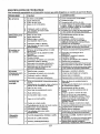
TROUBLESHOOTING
CHART:
See appropriate section in manual
PROBLEM
CAUSE
Will not start
Hard to start
unless
directed
to Sears
service
center.
1
2
3
4
Out of fuel.
1
Fill
fuel tank.
Bad spark plug.
Dirty air filter.
Water in fuel,
2
3
4
5
6
Loose or damaged wiring,
Engine valves out of adjustment.
Replace spark plug.
Glean/replace air filter,
Empty fuel tank and carburetor, refill
tank with fresh gasoline and replace
fuel filter,
Check all wiring.
Contact a Sears or other qualified
service center.
1 Didy air filter.
2 _Bad spark plug,
2, Weak or dead battery.
4 Stale or didy fuel.
!5
6
Loose or damaged wiring,
Engine valves out of adjustment.
5
16
1 Clean/replace air filter,
2 Replace spark plug.
3 Recharge or replace battery.
4 I Empty fuel tank and refill tank with
i fresh, clean gasoline,
5 Check all wiring,
6 Contact a Sears or other qualified
service center,
Engine will not
turn over
1
2
3
4
5
6
7
8
9
Clutchs/brake pedal not depressed.
Deck clutch is engaged.
Weak or dead battery.
Blown fuse.
Corroded battery terminals,
Loose or damaged wiring.
Faulty ignitionswitch.
Faulty solenoid or starter,
Faulty operator presence switch(es),
I
2
3
4
5
6
7
8
9
Depress clutch/brake pedal.
Disengage deck clutch.
Recharge or replace battery.
Replace fuse,
Clean batten./terminals.
Check all wiring,
Check/replace ignition switch.
Check/replase solenoid or starter,
Contact a Sears or other qualified
servme center,
Engine clicks but will
not start
1
2
3
4
Weak or dead battery.
Corroded battery terminals,
Loose or damaged wiring.
Faulty solenoid or starter.
1
2
3
4
Recharge or replace battery.
Clean battery terminals,
Check all wiring.
Check/replace solenoid or starter.
Loss of power
t
2
1
2
Raise cutting height/reduce speed
Clean underside of mower housing.
3
4
5
6
Cutting too much grass!toe fast.
Build-up of grass, leaves and trash
under mower.
Dirty air filter.
Low oil level/dirty ei[
Faulty spark plug.
Stale or dirty fuel.
3
4
5
6
7
Water in fuel.
7
Clean/replace air filter,
Check oil leve!/change oil.
Ctean& regap or change spark plug
Empty fuel tank and refill tank with
fresh, clean gasoline,
Empty fuel tank and carburetor,refill
tank with fresh gasoline.
8
Spark plug wire loose.
8
Connect & tighten spark plug wire,
9
Dirtyengine air screen/fins.
9
Clean engine air scrae_fins.
I0
Clean/replace muffler,
......
,,,,,,,,,,,,,,
10
Excessive
vibration
muffler.
wiring,
!11
Check all wiring.
out of adjustment,
t2
Contact a Sears or other qualified
service center.
11
Loose or damaged
12
Engine
1
i2
Engine continues to
run when operator
leaves seat with attachment clutch engaged
=Dirty/clogged
Worn.
valves
bent or loose
Bent blade
blade.
mandrel.
3
Loose/damaged
1
Faulty operator-safety
control system.
1
Replace blade. Tighten blade bolt.
, Contact a Sears or other qualified
service center,
3
Tighten loose part(s),
Replace damaged parts.
2
part(s),
presence
28
1
Check wiring, switches and
connections, If not corrected,
Contact a Sears or other qualified
sewice center.
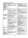
TROUBLESHOOTING CHART:
See
appropriate
section
PROBLEM
in manual
unless
directed
Sears service center.
tl
CAUSE'
CORRECTION
.... ,,,,, ,
,,,,,,,,,,,
,,,,, ,,,
Poor cut - uneven
cutting
t
2
3
14
Worn, bent or loose blade.
Mower deck not level.
1Buildup of grass, leaves, and trash
under mower,
Bent blade mandrel.
1
2
Replace blade. Tighten blade bolt.
Level mower deck,
3
Clean underside of mower housing.
4
C]ogged mower deck vent from
build.up of grass, leaves, and trash
around mandrel.
5
Contact a Sears or other qualified
service center.
Clean around mandrels to
open vent holes,
1
2
3
4
Mower blade will
not rotate
1
2
3
4
Obstruction in clutch mechanism.
Worn]damaged mower ddve belt.
Frozen idler pulley.
Frozen blade mandrel
Poor grass
discharge
1
2
3
4
5
Travel speed too fast.
Wet grass.
Mower deck not level.
Low/uneven tire air pressure.
Worn. bent or loose blade.
1
2
3
Shift to slower speed.
Allowgrass to dr,/before mowing.
Level mower deck,
4
5
Buildup of grass, leaves and
trash under mower.
Mower drive belt worn.
Blade improperly installed.
Improper blade used.
6
7
8
9
Clogged mower deck vent holes
from buildup of grass, leaves, and
trash around mandrels.
_o
Check tires for proper PSI,
Replace/sharpen blade. Tighten
blade bolt.
Clean underside of mower
housing.
Replace mower drive belt.
Reinstall blade sharp edge down.
Replace w_thblade listed in parts
manual,
i Clean around mandrels to
open vent holes.
Remove obstruction.
Replace mowerdrive belt.
Replace idler pultey.
Contact a Bears or other qual_ed
service center.
,,, ,,,,
10
7
8
9
,,,,,
1
2
3
Battery will not
charge
,,.,,,_,,
Bad battery cell(s).
Poor cable connections.
Fault,,/alternator.
1
2
3
Replace battery,
Check/clean al[ connections,
Replace aRemator,
1
tnstali axle key at rear wheel. See
'q'O REMOVE WHEEL" in the
Service and Adjustments section.
1
Turn ignition key to ROB "ON '_
2
position. Bee Operation section,
Allow engine warm-up by running for I
several seconds to several minutes. I
,,,,,,,,, ,,,
Axle key missing.
Loss of drive
,,,,,,,,, ,
i
Engine dies when
riding mower is
shifted into reverse
i2
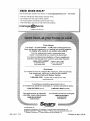
NEED MORE
...........
Reverse operation system (ROB)
is not "ON" while mower or other
;attachment is engaged.
Engine is cold,
HELP?
You'll find the answer and more on managemyhome.com
• Find this and atl your other
product
manuals
online.
• Get answers from our team of home experts.
• Get a personalized
• Find information
manage
maintenance
and tools
p[an for your
to help with
home.
home projects.
home
brought to yeu by Sez=_rs
29
- for free!
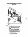
SUGGESTED
GUIDE
FOR SIGHTING
SLOPES
ONLY RIDE UP AND
NOT ACROSS HILL
15 DEGREES
DOWN
FOR SAFE OPERATION
HILL,
MAX.
down the face of slopes, never across the face. Do not mow
WARNING: To avoid serious injury, operate your tractor up and
slopes greater than 15 degrees. Make turns gradually to prevent
tipping or loss of control. Exercise extreme caution when
changing direction on stopes.
1. Fold this page along dotted line indicated above.
2. Hold page before you so that its left edge is vertically parafle! to a tree
trunk or other upright structure.
3. Sight across the fold in the direction of hill slope you want to measure,
4. Compare the angle of the-fold with the slope of the hill.
Garantfa ............................................ ,.,, 31
Reglas de seguridad ............................. 32
Especificaciones del producto .............. 35
EnsambladoiPreoperaci6n ................... 36
Operaci6n ............................................. 40
Garantia
para
GARANTiA
equipos
COMPLETA
tractores
Programa de mantenimiento ................
Mantenimiento ......................................
Servicio y Ajustes .................................
Almacenamiento ...................................
SotuciSn de problemas .........................
47
47
52
56
57
Craftsman
DE CRAFTSMAN
PeR DOS At-JOS desde la fecha de compra, todas las pai'tes no sustituibles de eete eqUZpo tractor estdn
garantizadas contra cualquier defecto de material o mane de obra. Una parle no sustituible defectuosa
recibir& reparaciSn o reemptazo gratuito en casa si la reparaci6n es imposible.
PeR CINCO ANOS desde la fecha de compra, e] bastidor y el eje delantero de este equips tractor est&n
garantizados contra cualquier defecto de material o mane de obra. Un bastictor o eje delantero defectuoso
recibir& reparaciSn o reemplazo gratuito en casa sila reparaciSn es imposible.
DURANT_ 90 DiAS desde la fecha de compra, ta baterla (una parle sustituible) de este equipo tractor
est& garantizada contra cua[quier defecto de material o mane de obra (nuestra prueba comprueba que no
contendr& carga). Una bateda defectuosa recibir& un reemp|azo gratuito en casa.
GARANTJA LIMITADA DE PeR VIDA ADICIONAL en el EJE DELANTERO
DE HIERRO COLADO (sJ
est_ prov[sto)
DURANTE EL TIEMPO EN QUE SE USE per el propietario original despu_s del quinto a_o a partir de [a
fecha de compra, el eje delantero de hierro colado (si est_ provisto) de este equipo tractos est_ garantizado
contra cualquier defecIo de mateda[ o mane de obra. Con el comprobante de ¢ompra, un eje delantero de
hierro colado recibir& un reemplazo gratuito en casa.
SERVICIO
DE GARANTIA
Para conocer los detalIes de la cobertura de garantia para obtener una reparaci6n
I[am_ aI 1-800-659-5917
6 visite el sitio web: www. craftsman.corn
o reemplazo
gratuito,
En todos los cases anteriores, si el reemplazo es lmposible, el equipo tractor ser,'_sustituido sin cargo con
el mismo modelo o uno equivatente.
Toda [a coberlura de garantia anterior ser,_ nufa si este equipo tractor se utiliza alguna vez para brindar
servicios comerciales osi se alquila a otra persona.
Eeta garantiacubre _INICAMENTEdefectos
de materialy mane deobra. La coberturade garantfa NO incluye:
• Panes sustituibJes (excepto la bateria) que se puedan desgastar per el use normal dentro del periodo de
garantia incluso, pete sin timitarse a, cuchillas, buj(as, fittros de aire, correas y fillies de aceite.
• Servicios de mantenimiento est&ndar, ¢ambios de aceite o afinaciones.
• Reemplazo o reparaciSn de neum_,ticos per pinchazos causados per objetos externos come clavos,
espinas, 'tocones o vittles.
• Reemp[azo o reparaci6n de neum_ticos o ruedas per desgaate normal, accidentes o per operaci6n o
mantenimiento incorrectos.
• Reparaciones necesar_as pot abuse del operador incluso, pete sin limitarse a, daSos causados per
remolcar obietos que superen la capacidad del equipo tractor, chocar contra objetos que doblen el
baetidor, el ensamble del eje o el cig0ef_al o sobrepasar la velocidad del motor.
• Reparaciones necesarias per negligencia del opeTador, Incluso (pete sin timitarse a silo) dafios el_ctricos
y mec&nicos causados porel almacenamiente incorrecto, per no usarel grade y la cantidad correctos de
aceite de motor, per no mantener del muelle fibre de residues inflamables o per no mantener el equipo
tractor de acuerdo con lz,s instrucciones que contiene el manual gel operador,
• Limpieza o reparaciones
deI motor (sistema de combustible) cuando se determina que se us6
combustible contaminado y oxidado (sarro). En general, et combustible debe usarse dentro de los 30
dias posteriores a su compra.
• Deterioro y desgaste normal de los acabados exterioras o sustituci6n de r6tulos de productos.
Esta garantia re otorga derechos legales espectficos, y usted tambi_n puede tenet otros dereohos que
vat[an de un estado a otro.
Sears Brands Management Corporation, Hoffman Estates, IL 60179
31
PELIGRO: Esta Maquina cortadora es capaz de amputar las manosy los pies y de lanzar objetos. si no se observan |as instruceiones de seguridad siguientes se pueden producir lesiones
graves o ta muerte.
_lb ADVERTENCIA: Con el fin de prevenir un
arranque accidental cuando configure, transporte,
ajuste o repare la m&quina, siernpre desconecte
el cable de la bujia y coloque el cable deride no
pueda entrar en contacto con la bujia.
_I, ADVERTENOIA: No descienda per una
colina en neutral, pues puede perder et control
de la cortadora de cesped.
_ADVERTENOIA:
El escape deI motor, algunas de sus partes y ciertos componentes del
vehfcu]o contienen o em_ten productos quimicos
de los que se sabe en el Estado de California que
causan c&ncer y defectos de nacimiento u otros
daSos reproductivos.
_ADVERTENOIA:
Esta unidad no es para
usarse con pesas para ruedas. Use s61o accesorios disehados especificamente para esta
cortadora de c_sped.
_I_ ADVERTENCIA: Los postes, las terminates
y los accesorios relacionados de Ia baterfa contienen plomo y compuestos de plomo, productos
quimicos de los que se sabe en el Estado de
California que causan c&ncer y defectos de nacimiento u otros da_os reproductivos.
I. OPERAGION
GENERAL
• Lea, entienda y siga todas las instrucciones
sobre ta m&quina en el manual antes de comenzar,
• No co]oque Jas manes ni los pies cerca de
ias partes giratorias ni debajo de la m&quina.
Mant_ngase alejade de la abertum de descarga
en todo memento.
• $61o permita que los aduitos responsables,
que est_n familiarizados con las instrucciones,
operen la m_.quina.
• Libere el &rea de objetes come piedras, juguetes, cables, etc., pues podrian atraparse y
lanzarse con la cuchilla.
• AsegSrese de que el area est@libre de curiosos antes de operar la m_quina, Detenga la
m_.quina si alguien entra en el &rea,
• Nunca transporte pasajeros.
. No corte en reversa, a menos que sea absolutamente necesario. Siempre mire hacia abajo
y hacia atr&santes y cuando vaya en reversa.
• Nunca dirija el material que se descarga hacia
nadie. Evite descargar el materis] contra una
pared u otra obstruccibn. El material puede
rebotar hacia el operador. Detenga la cuchilla
cuando cruce per superficies con grava,
32
• No maneje la m&quina si no tiene el colector
de c_sped complete, la canaleta de descarga
u otres dispositivos de seguridad en su Iugar
y en fiJncionamiento.
• Desacelere antes de dar la vuelta.
• Nunca deje la m&quina en funcionamiento sin
vigilar. Siempre detenga la cuchilla, active el
freno de estacionamiento, detenga et motor y
retire la Ilave antes de descender.
• Desactive ]a cuchilla cuando no est6 cortando
c_sped. Apague el motor y espere hasta que
todas las partes so detengan per complete
antes de limpiar Jam&quina, retirar el colector
de c@spedo destapar la canaleta de descarga.
• Opere la m&quina enicamente durante el dia
o con buena luz artificial
• No opere la m&quina mientras est_ bajo la
influenciade alcohol o drogas.
• Est6 pendiente del tr&fico cuando opere la
m&quina cerca de caminos o al cruzarlos.
• Tenga cuidado extreme cuando cargue o descargue Ia m_quina de un trailer o cami6n.
• Use siempre protecci6n ocu[ar cuando opere
la m&quina,
• Los datos indican que los operadores de 60 6
m&sa5os de edad entran en un alto poroentaje
de lesiones relacionadas con cortadoras do
c_sped, Estos operadores deben evaiuar su
habilidad para operar la cortadora de c6sped
en forma suficientemente segura come para
protegerse a s_mismos y a los dem&s de una
lesi6n grave.
• Mantenga la m_.quina libre de cualquier
acumuiaci6n de e_sped, hojas u otra basura,
pues podrian entrar en contacto con e] escape
caliente y!o Ias partes del motor y quemarse.
No permita que la plataforma de la cortadora
de c_sped levante hojas u otra basura que
pueda causar acumu]aciones. Limpiecualquier
derrame de aceite o combustible antes de
operaro almacenar la m&quina. Permita que
la m&quina se enfrie antes de almacenarla,
II. OPERACION
EN PENDIENTES
IlL NiI_IOS
]_as pendientes son un factor principal que se
relaciona con Ia p6rdida de control y Josaccidentes de voicaduras, Io que puede dar come
resultado una lesion grave o la muerte. La
operaci6n en ted,s las pendientes requiere
tener precauciones extras. Si usted no puede
retroceder de una pendiente o si se siente
inc6modo en la pendiente, no la pode.
•Pode las pendientes hacia arriba y hacia abajo
(a 15° come mdximo), no de un Iado a otro.
• Tenga cuidado con los hoyos, surcos, protuberancias, piedras y otros objetos ocuitos. El
terreno disparejo podr(a vofcar la mdquina. El
c_sped alto puede esconder los obstdculos.
- EUjauna velocidad terrestre baja de mode que
no tenga que detenerse o girar mientras est_
en la pendiente.
• Nocorte eWc_spedh_medo. Lasllantas pueden
pettier su tracc(6n.
• Mantenga siemprela m_.quina en una velocidad
cuando baje per las pendientes. No cambie a
neutral ni vaya en punto muerto hacia abajo
en una colina.
• Si (a m_.quina se para mientras sube per una
colina, desactive la cuchilla, cambie a reversa
y baje despacio.
• Evite arrancar, parar o girar en una pendiente.
Si las ]lantas pierden su tracci6n, desactive la
cuchilla y proceda con lentitud en tfnea recta
hacia abajo per la pendiente.
• Mantenga todo el movimiento lento y gradual
sobre {as pendientes. No haga cambios repentinos de velocidad o direcci6n, pues podHa
causar que ]a mdquina se vuelque.
• Tenga cuidaod extreme mientras opera la
m_quina con colectores de c_sped u otros
accesodos; pueden afectar [a estab]lidad de
la m&quina.
- No la use sobre pendientes pronunciadas.
• No (ntente estabilizar Ia m&quina poniendo et
pie en el sue]o.
° No corte cerca de deciives, zanjas o terraplenes.
La m_.quina podr(a volcarse de repente si una
rueda pasa sobre (a oriUa o si la or(lla termina
en un hoyo.
Pueden ocurrir accidentes trdgicos si el operador
no est_ alerta ante (a presencia de ni_os. Con
frecuencia (os niSos se sienten atraidos per
la mdquina y la actMdad de corte de c_sped.
Nunca d_ per un hecho que los ni_os permanecer_.n deride usted los v(o per 5ltima vez,
• Mantenga a los niSos alejados delbrea de eorte
y bajo la superv(siSn de un adulto responsable
a parte del operador.
° Est_ aEerta y apague ta mdquina si un niSo
entra en el &tea.
• Antes y mientras avance en reversa, mire hacia
atrds y hacia abajo per si hay ni(_os presentes.
• Nunca I(eve niSosarriba dela mdquina, incluso
cuando (a cuchilla est_ desactivada. Pueden
caerse ylesionarse gravemente o interfer(r con
la operaci6n segura de ta mdquina. Los niffos
a quienes se les da una vuelta en la m_.quina
pueden aparecer de repente en el &tea de corte
para otra vuelta y set atrope]lados o golpeados
con la m_quina.
• Nunca permita que los nir_osoperen la m&quina.
• Tenga cuidado extreme a] aeercarse a las
curvas sin visibilidad, arbustos, drboles u otros
objetos que puedan bloquearsu vision e Jmpedir
observar a un nile.
W. SERVIClO
manejo seguro de la gasoUna
Para evitar una Jesi6npersonal o un daSo en (a
propiedad, tenga cuidado extreme al manejar
ia gasolina. La gasolina es extremadamente
inflamable y los vapores son explosives,
• Apague los cigarrillos,habanos, pipas y otras
fuentes de ignici6n.
• Use s61o un recipiente de gasolina aprobado.
• Nunca retire el tap6n de Ia gasolina ni agregue
combustible con el motor en funcionamiento.
Permita que el motor se enfrie antes de volver
a Uenar e( tanque de combustible.
• Nunca Ilene la m&quina de combustible en
(nterieres.
• Nunca a(macene la mdqu(na o el recipiente
de combustible donde haya una flama abierta, chispa ouna (uz de p(loto come Ia de un
calentador de agua u otros aparatos.
33
• Nunca ]lene los recipientes adentro de un
vehiculo o en un cami6n o trailer con forte de
pl&stico. Coloque siempre los recipientes en el
suelo y Iejos de su vehiculo du_ante el Ilenado.
• Retire el equipo qua flJnciona con gasolina del
cami6n o trailer y rellOnelo en el suelooSi esto
no es posible, entonces reIlene este equipo
con un recipiente port&tiI, en lugar de hacerlo
directamente con Ia boquilla del dispensador
de gasotina.
• Mantenga la boquilla en contacto con el borde
del tanque o recipiente de combustible abri_ndote en rode memento basra qua el llenado
de combustible est_ complete. No use un
dispositivo que mantenga abierta Ia boquilla.
• Si el combustible se derrama sobre la ropa,
c&mbiesela de inmediato.
• Nunca Ilene de m&s el tanque de combustible.
Vuelva a colocar el tap6n de la gasolina y
apri6telo bien,
SERVICIO
GENERAL
- Nunca opere la maquina en un _.rea cerrada.
• Mantengatodas]astuercas y pemos apretados
para asegurarse de qua el eq uipo se encuentra
en condiciones de trabajo seguras.
• Nunca manipule los dispositivos de seguridad.
Revise con regularidad que operen bien,
• Mantenga Ia m&quinalibre de cualquier acumulaci6n de c6specl, he]as u otra basura. Limpie
los derrames de aceite o combustible y retire
cualquier basura que contenga combustible,
Permita que la m&quina se enfrie antes de
almacenarla.
• Si usted golpea un objeto extrafio, det@ngase
e inspecciona ia m&quina. Rep_.rela, de ser
necesario, antes de volver a empezar.
. Nunca haga ajustes o reparaciones con el motor
en funcionamiento.
• Revise !os componentes del colector de c_sped
y la canaleta de descarga con frecuencia y
sustituya con repuestos recomendados per el
fabricante cuando sea necesario.
- La cuchillade la cortaclorade c_sped tie_e file.
Envuetva la cuchilla o use guantes y tenga
precauci6n extrema cuando Ies d_ servicio.
• Revise ta operaci6n deI freno con frecuencia.
Ajuste y d_ servicio segt3n sea necesario.
• Conserve o cambie las etiquetas de seguridad
e instrucciones seg_n sea necesaxio.
• Aseg_rese de que el &rea est_ Iibre de curiosos antes de operar la m_.quina. Detenga la
m&quina si alguien antra en el &rea,
• Nunca transporte pasKleros.
• No corte en reversa, a menos que sea absolutamente necesario. Siempre mire hacia aba|o
y hacia atr&s antes y cuando vaya en reversa.
34
ESPECIFICACIONES
DEL PRODUCTO
Capacidad de
gasolina y Tipo:
Tipo de Aceite
(APi-SG-SL):
Capacidad
de aceite:
1,5 GaIlones (5,6 L)
Regular sin pJomo
._
SAE 30 (Sobre 32°F/0°C)
SAE 5W30 (Deabajo32OF/0_C
48 onzas
Bujfa:
Champion RC12YC
(Abertura: .030"/0,76 ram)
Marcha
Adelante:
0 - 4/6,4
Atr&s:
0 - 2/3,2
Velocidad de
Recarrido:
_ph/Kph)
Sistema de
Carga
:3 Amps Bateria
PARA
Congratu]acionesporsu buena compra. Su nuevo
producto Craftsman® estd diseSado y fabric.ado
para'_Jncionarde modo ffable por muchos aSos.
Pero como todos los productos, puede neees_ar
alguna reparacibn de tanto en tanto. En este ca.so
tener un Acuerdo de Protecci6n para la Reparaci6n puede hacerles ahorrar dineroy fastidios.
Compre ahora un Acuerdo de Protecci6n para
la Reparaci6n y prot6gese de mo]estias y gastos
inesperados.
Un Acuerdo incluye los puntossiguientes:
° Servicio experto de nuestros12.000 especialistas profesionales en la reparaci6n.
* Servicio i|imitado sin cargo alguno para
las partes y ta mano de obra sobre todas Ias
reparaciones garantizadas.
Torque deI perno 45-55Pies/lJbras(62-75Nm)
de la ¢uchilla:
FELICITACIONES pot la compra de su cortadora
de c_sped. Ha sido diseSado, planificado y fabricado para darle ta mejor confiabiJidad y et meier
rendimiento posible.
En el caso de que se encuentre con cualquier
problema que no pueda solucionar fdcilmente,
haga el favor de ponerse en contacto con un
centro de servicio Sears o con un otto centro de
servicio cualificado. Cuenta con representantes
bien capacitados y competentes y con las herramientas adecuadas para darle servicio o para
reparar este cortadora de c_sped.
Haga el favor de leer y de guardar este manual.
Estas instruc-ciones le permitir&nmontar y mantenet su unidad en forma adecuada. Siempre
observe las "REGLAS DE SEGURIDAD."
RESPONSABILIDADES
ACUERDOS
DE_ PROTECClON
LA REPARACION
DEL CLIENTE
• Lea y observe las reglas de seguridad.
• Siga un progmma regular at darle mantenimiento, cuidados y uso a su cortadora de c_sped.
• Siga Ias instrucciones de las secciones de
"Mantenimiento" y '_.lmacenamiento" de este
manual del propietario.
_IbADVERTENClA:
Esta cortadora de cL=s
_
pedestd equipada con un motor de combusti6n
interna y no se debe usar en o cerca de terrenos
cubier_osde bosques sin mejoras, cubiertosde
arbustos o cubiertos de pastos, a menos que
el sistema de escape de] motor est_ equipado
con un parachispas que cumpla con Ias leyes
locales o estatales aplicables (de habedas). Si
se usa un parachispas, el operador deberd dade
mantenimiento en un orden de trabajo efectivo.
En el estado de California, las Ieyes exigen el uso
de un parachispas (Secci6n 4442 de| C6digo de
Recursos P0blicos de California). Otros estados
pueden tener leyes similares. En los terrenos federales se ap]ican las ]eyes federales. Se puede
obtenerun parachispasparae[silenciadoratrav_s
del centro de servicio autorizado rods cercano.
35
* Sustituci6n del producto si su producto
garantizado no puede set arreglado.
,
Descuento de110% sobre el precio corriente
del eervicio y de las partes refativas al servicio
no cubiertas por el acuerdo; tambi_n el 10%
menos sobre el precio corriente de un control
de mantenimiento preventivo.
- Ayuda rdpida por tel_fono- soportetelef6nico por parte de un representante Sears sobre
productosque requieren un arreglo en casa, y
adem&s una programaci6n sobre los arreglos
mas convenientes.
Cuando se ha comprado el Acuerdo, basta con
unaIlamadatelef6nica para programarel servicio.
Puede Ilamar cuando quiera, dJa y noche o fijar
en linea una cita para obtener el servicio. Sears
tiene rods de 12,000 especialistas profesionales
en Ia reparaci6n, que tienen acceso a rods de
4.5 millones de partes y accesorios de calidad.
Este es el tipo de profesiona]idad con que puede
contar para ayudar a alargar la vida del producto que acaba de comprar, por muchos aries.
iCompre boy su Acuerdo de Protecci6n para Ia
Reparaci6nJ
Se aplican algunas limitaciones y exclusiones.
Para conocer los precios y tener rods Informaci6n, llame al 1-800-827-6655.
SERVICIO
DE INSTALACION
SEARS
Para la inetalaeidn profesional Sears de aparatos de casa, puertas de 9araje, calentadores de
agua y otros importantes articu]os para la casa,
en U.S.A IJamar a
1-800-4-MY-HOME@
Volante
(t) Parachoques
de la direcci6n
traseros
(t) Pamchoques
delanteros
de direcci6a
(1) 5/t6-18 x4
Pemo de cabeza
(1) Arandela
de seguridad
-Cobe_tura
hexagonal
(4) Tomillo
#t0 x 0,200
E×tenci6n
Adaptador
(1) Shroud
(1) Arandela
(1) Arandeias
taza
D
(2)Llave
Hoja de
pendiente
Asiento
(1) Manilla
de ajuste
Su nueva cortadora de c@sped se ha ensarnblado en la f&brica con excepci6n de aquellas partes
que se dejan sin ensamblar para eJenvio. Para asegurar la operaci6n segura y correcta de la cortadora de c6sped, todas las partes y la ferreteria que usted ensamble se deben apretar bien. Use las
herramientas correctas necesarias para asegurar un ajuste apropiado.
HERRAMIENTAS
NECESARIAS
EL ENSAMBLADO
PARA
El ensamblado ser& m#,s simple si cuenta con
un conjunto de llaves de cubo. Los tamarios de
I[ave est#tndar que necesitase indican en seguida.
(1) Llave de 1/2"
(I) Herramienta de cuchilla
(1) Calibrador de presi6n para Ilantas
Cuando se menciona la derecha o la izquierda
en este manual, esto significa cuando usted se
encuentra en Ia posicibn de operaci6n (sentado
al volante).
RETIRO
DE LA CORTADORA
DE
LA CAJA DE CARTON
NOTA: $61o corte la caja de cart6n con una
herramienta de cuchilla corta, pues una de
cuchilla larga o una sierra pueden pinchar Tas
Ilantas de la unidad.
COMO CONFIGURAR SU
CORTADORA DE ClaSPED
REVISE LA BATERiA
AsegSrese de que la bateria est@bien sujetada,
y que todos los cables est_n bien conectados.
•
•
La bateria est_ ubicada debajo del asiento.
La bateria se ha cargado por completo en la
fAbriea antes de su instalaci6n.
CF_SPED DE
DESEMPACADO
DE LACAJA DE CARTON
t.
Retire todas Ias partes sueltas aecesibles y
las cajas de las partes deI cart6n.
2. Corte las lineas punteadas de los cuatro
paneles de Ia caja de cart6n. Retire la caja
de cart6n y el marco superior come una sola
pieza,
3, Retire los matedales de empaque de Ia cortadora de c6sped,
4, Revise si hay cualquier parte sueltao cartones
adicionales y retfrelos,
36
•
Aslento
teria
PARA INSTALACI6N DE COLUMNA DE
DIRECCION
6.
7.
Deslice eI eje de extensi6n sobre el eje de
direcci6n.
Des]ice ia cubierta de espuma de protecci6n
del eje de direcci6n sobre el eje de direcci6n.
3. Coloque eI manguito de direcci6n sobre e]
eje de direcci6n y empSlejo hacia abajo para
asegurarlo.
4. Coloque Iasruedas delar_erasde [acortadora
de cL=sped de mode que apunten en Ifnea
recta hacia adelante.
5. Retire el adaptador del volante y deslice el
adaptador sebre el eje de direcci6n.
7. Presione el volante en su posici6n sobre el
eje, instale Ia arandela grande, bIoquee ta
arandela y apriete bien el perno.
8. Coloque bien el inserto deIvolante en eI centre
del volante,
2,
8.
9.
Baje el asiento a la posici6nde operaci6n y
si_ntese en el asiento.
Deslice el asiento hasta que I[egue a una
posici6n c6moda, que ]e permita presionar
eI pedal deI embrague/freno completamente
hasta abajo.
Desmbntese del asiento sin mover su
posici6n ajustada.
Levante el asiento y apriete ta manilla de
ajuste en forma segura,
Base del
Asiento
Perno
Arandela_
Inserto
planagrande
j_-_
Volante
de direcci6n_
......
"-_
"r-'--
=._x.\.
de ladirecci6n---'-_
_
Cubierta
°
"_
Manilla de
Adaptador
//_
Eje de
/#"_...
/_
PARA INSTALACI6N
NOTA: Ahem puedesacar la cortadorade c6sped
de latarima. Observe las siguientes instrucciones
apropiadas para retirar la cortadora de c_sped
de la tarima,
Ejede
_-direcci6n
ADMERTENCIA: Antes de empezar, lea,
entienda y siga todas las instrucciones de la
secci6n de Operani6n de este manual. AsegSrese
de que la cortadora de cL,sped est_ en un &rea
bien ventilada, Aseg_rese de que el &rea de
enfrente de la cortadora de c_sped est_ libre de
gente y objetos.
DEL ASIENTO
Ajuste el asiento antes de apretar la manilla de
ajuste.
1. Remueva [a manilla de ajuste y la arandeta
plana que aseguran el asiento aI empaque
de cart6n y p6nga[os de lade para poder
utilizarlos durante la instalaci6n del asiento
sobre el tractor.
2. Remueva y desechese del embalaje de
cart6n.
3. Colocar el asiento y en el asiento del recipiente de manera que la tres (3) cojins est_
posicionada en el agujero ancho ranurado
en el recipiente,
4. Empujar en el asiento para enganchar eI
cojins en la ranura y ernpujar el asiento
hacla la parte tra_serade1tractor,
5. Pivotear el asiento y el recipiente hacia adelante y ensamblar el bot6n de regulaci6n
y la arandela taza de mode no fuerte. No
apretar enroscar fuerte,
PARA SACAR LA CORTADORA
DE ClaSPED DE LA TARIMA (Consulte Ia secci6n
de Operaci6n
para ver la ubicaci6n
y
funci_n de los controles)
1, Eleve lapatanca delelevador de Ia plataforma
hasta su posicibn m_xima,
2, Sue[te el freno de estacionamiento al Iiberar
et pedal deI embrague_eno.
3. Cambie unidad a la posicidn de neutro.
4, Saque la cortadora de c_sped de ]a tarima,
37
COLOCACION
DELANTERA
DE LA DEFENSA
NOTA: Para que el armado le resulte senciIIo,
puedesolicitar ayudaa otra persona cuando monte
la defensa en la cortadora de c_sped.
1.
Retire los tornillos (2) deI chasis delantro de
la cortadora de c_sped.
2,
Incline la defensa delantera de modo que las
pestaSas de la defensa entrenen las ranuras
del frente del chasis y baje la defensa hacia
su tugar.
Coloque Ia defensa en el frente del chasis
con los tornillos que retir6 en el paso t.
Apriete bien los dos (2) tornJll0s.
3.
4.
REVISE
LA PRESION
DE LAS LLANTAS
Las Ilantas de la cortadora de c6sped se inflaron
de rn&s en la f&bdca para su transporte, Corregir
la presi6n de las Ilantases irnportantepara obtener
el mejor desernpeSo deI corte.
• Reduzca la presi6n de tas Ilantas a Ia PSI que
se rnues_traen las llantas.
REVISE LA NIVELACION
DE LA
PLATAFORMA
Para obtener los rnejores resultados de corte, la
carcasa de lacort_dorade c@spedse debe nivelar
bien. Consulte la parte de "NIVELACION DE LA
CARCASA DE LA CORTADORA DE CESPED" en
ta secci6n de Servicio y Ajustes de este manual,
5.
6.
Coloque fa envoitura de pl_.stico sobre la
defensa conforrne se muestra y ens&mbleta
holgadarnente en Ia defensa con los euatro
(4) tornill0s provistos.
Apriete bien los cuatro (4) tornitlos.
Envoltura
COLOCACION DELADEFENSATRASERA
NOTA: Para que el arrnado le resulte sencillo,
puede solicitar ayudaaotrapersonacuando mente
Ia defensa en la cortadora de c@sped.
1.
Retire los tornillos (4) del chasis trasero de la
cortadora de c_sped,
2. Coloque la defensa eonforme se muestra
y ensAmblela en el ehasis trasero con Ios
tornillos que retir6 en el paso 1.
3. Apriete bien los cuatro (4) tornillos.
38
REVISE LA POSlClON CORRECTA
DE LA CINTA DEL IMPULSOR DE LA
CORTADORA
DE CESPED
Observe la figura que se rnuestra para cambiar la
cinta deI irnpulsor de la cortadora de c_sped en
la secci6n de servicio y ajuste de este manual.
Verifique que la cinta est6 en la ruta correcta.
REVISE EL SISTEMA DE FRENO
Despu@sde que haya aprendido c6mo operar su
cortadora de c6sped, revise que el freno funcione
bien. Consu3te la parte de '_,JUSTE DE FRENO"
en lasecci6n deServicio yAjustes deeste manual.
t_LtSTA
DE REVISION
Antes de operar su nueva cortadora de c6sped,
deseamos asegurarnos de que usted obtenga el
mejot desempeSo ysaUsfacci6nde este Producto
de Calidad.
Por favor revise la siguiente lista de revisi6n:
J
Todas Ias instrucciones de ensamblaje se ban
completado.
•/
No queda nhguna parte suelta en ]a caja de
cartbn.
La bateria est& bien conectada.
J
,/
Et asiento est& ajustado c6modamente y bien
apretado.
,/ Todas las Ilantas estdn bien infladas. (Las
Ilantas se inflan de m&s en [a f&brica para su
transportaci6n.)
,/ AsegQrese de que la plataforma de lacortadora
de c_sped est_ bien nivelada de lado a lado
y del frente a la parte posterior para obtener
los mejores resultades de corte. (Las Ilantas
deben estar bien infladas para ia nivelaci6n.)
€" Revise la cinta de la cortadora de c(_sped.
Aseg_rese de que est_ en la ruta c0rrecta
alrededor de las poleas y adentro de todas
las sujeciones de la cinta.
•/ Revise el cableado. AsegSrese de que todas
[asconexiones est6n bien co]ocadas y que los
cables est_n bfen sujetos.
AI aprender c6mo usar su cortadora de c_sped,
preste atenci6n extra a los siguientes puntos
importantes:
,/ Elaceite deI motorest_ en un nivel adecuado.
,/
,/
,/
,/
El tanque de combustible est_ lleno con gasolina sin plemo regular nueva y limpia.
Familiar|cese con todos los controles, su ubicaci6n y funci6n. Op_re[os antes de arrancar
el motor.
AsegQrese de que el sistema de freno est_ en
condiciones de operaci6n seguras.
Asegurarse de que el Sisterna de Presencia
del Operador y el Sistema de Funcionamiento
Atr&s (ROS) funcionan de modo adecuado
(Ver las Secciones de Funcionamiento y
Mantenimiento en este manual.)
39
Estos simbolos pueden aparecer en ta cortadora de c_sped o en Ia literatura provista con el producto, Aprenda y entienda su significado.
R
MAP_CHA
N
ATR._S
H
NEUTRO
8AJO
I, al41
6
MOTOR
APAGADO
ESTRANGULAOI6N
MOTOR
ENCENDtCO
MOTOR
ENMARCHA
ACCESORIO
DEL
EMBRAGUE
ENGANCHADO
LENTO
INTERRUPTER
BE IGl',_,lC[(:) N
PRESION
FRENO
DEL ACE|TE
MANe
DE
FRENO
SE CERR(_
DE
MANO ABIERTO
(SOS)
;i;
BOB£E LUZ DE
TEMPERATURAS
R,_'PIDO
G
SISTEMA
FUNCIONAM[ENTO
ATR_,B
i\1
L
ALTO
COMBUSTIBLE
PRESI_,N
DEL ACE_E
ACCESORIO
DEL
EMBRAGUE
DESENGANCHADO
BATERiA
MARCHA
ATRP, S
PELIGRO, GUARDE
LAB
MANOSY
LOS PIES LEJOS
+
MAROHA
HAC|A AOELANTE
ALTURA
DE LA
SEGAOORA
MANTENGA
EL
AREA DESPE, JADA
LEVANTAMIENTO
DE LA SEGABORA
PELIGROS
DE
PENDIENTES
(YeaIa secci6n_e las reglasde segurJdad)
CONTROLOE
DESAC_VAOO
RUEDA MBRE
ADVERTENCIA indica un peligro que, si no Be evita,
puede provocar muerte o lesiones graves.
FRENOtEMBRAGUE
PEDAL
PELIGRO indica un peligro que, si no se evita,
proveca muerte o lesiones graves.
DE
PRECAUCI()N indica un peligro que, si no se evita,
puede provocar lesiones ligeras o moderadas.
CONTROLDE
RUEDA UBRE
ACTWADO
No seguir las siguientes instrucciones
puede provocar heridas o muerte. Los
sfmbolos de aviso de seguridadse utilizan
para identifiear informaciones de seguridad
relativas a peligros que puedenprovocar ta
muerte, heridas graves y/o dafios a la
ma.quina.
PRECAUCI(_N
se utiliza
sin elprovocar
sfmbolo de
aviso, indica unacuando
situaeJ6n
que puede
da_os al tractor y/o al motor.
SUPERFICIES CALIENTES indica un peligro que,
si no se evita, puede provocar la muerte, lesiones
graves yto danes a la mdquina.
FUEGO indica un peligro que, si no se evita, puede
provocar la muerte, lesi0nes graves y/o danes
a Ia mdquina.
4O
CONOZCA SU CORTADORA DE ClaSPED
LEA ESTE MANUAL DEL PROPtETARIO Y LAS REGLAS DE SEGURIDAD ANTES DE OPEPAR SU CORTADORA DE ClaSPED
Compare las ilustraciones con su cortadora de c_sped para familiarizarse con las ubicacionesde los
diferentes controles y ajustes, Conserve este manual para futuras consultas.
Pedal dei freno
Freno de
(ROS) en
posici6n "on"
Palanca del
embrague de Ia
E_mbolode la
palanca del
=ptor
de arranque
Aceleraci6ni
EstrangulaoiSn
de ajuste
de altura
de
controlde
movimiento
Nuestra cortadorade c6spedcumple con las normasde seguridad aplicables de]
Institute Nacional Estadounidensede Normas.
PALACA DEL EMBRAGUE DE LA PLATAFORMA - Se usa para activar la cuchilla de la
cortadora de c_sped.
PALANCA DE FRENO DE ESTACIONAMIENTO
- Fija el freno de estacionamiento en la posici6n
de freno.
PALANCA DE CONTROL DE MOVIMIENTO Selecciona lavelocidad y direcci6n de la cortadora
de c_sped.
|NTERRUPTOR DELSISTEMA DE FUNCIONAMIENTO HACIA ATRAS (ROS) EN POSICI6N
"ON" - Permite laoperaci6n delconjuntosegador
o otroaccesorioaccionado mientrasqueen rev_s.
CONTROL DEACELERACION/ESTRANGULACION - Se usa para hacer arrancar y controlarla
velocidad deI motor.
FRENO DE ESTACIONAMIENTO- Se usa para
frenar la certadora de c6sped y arrancar el motor,
PALANCA DE AJUSTE DE ALTURA - Se usa
para ajustar Ia altura de corte de Ia cortadora
de c@sped.
INTERRUPTER DE ARPANQUE - Se usa para
arrancar y detener e[ motor.
I_MBOLO DE LA PALANCA DEL ELEVADOR Se usa para soltar la palanca de ajuste de altura
cuando se cambia su posioi6n.
41
La operaci6n de cualquier cortadora de c_sped puede causar que entren objetos extraEos en los ojos, 1oque puede provocar un daEo severe en los mismos. Use siempre
lentes de seguddad o protecciones oculares mientras est_ operando la cortadora de
c_sped o realizando cualquier ajuste o reparaci6n. Se recomienda usar una careta
de seguridad de visi6n amplia sobre los anteojos o lentes de seguridad est&ndar.
COMO USAR LA CORTADORA
DE
CESPED
ACTIVAClON
DEL FRENO DE ESTACIONAMIENTO
IMPULSI6N DE RECORRIDO -
La cortadora de c_sped est_ equipada con un
interruptor de detecci6n de presencia del operador. Cuando el motor est_ en funcionamiento,
cualquier intento del operador de dejar el asiento
sin primero activar eJfreno de estacionamiento
apagara el motor.
1.
2.
Presione el pedal deI freno completamente
hasta abajo y mant_ngalo presionado.
Jale y sostenga la palanca del freno de estacionamiento hacia arriba, libere la presibn
del pedal de freno y {uegosuelte Ia palanca
de! freno de estacionamiento. El pedal debe
permanecer en posiciEn de frenado. Aseg6rese de que el freno de estacionamiento
mantendr& detenida la cortadora de c6sped.
* Para parar el mecanismo impulsor,presione el
pedal del freno completamente.
, Mueva la palanca de control de movimiento a
la posici6n de neutro.
q ._._____----Palancade controlde movimientc_
MOTOR • Mover Ia palanca de mando entre la posici6n
de velocidad media y m&xima (r&pida).
AVISO:Si no se mueve la palanca de mando
entre Ia posiciEn de velocidad media y m_xima
(r&pida), antes de pararse, se puede causar un
"retorno de llama" deJ motor.
Control De
Acelemci6n
PARADA
CUCHILLA DE LA CORTADORA DE C_:SPED • Para detener la cuchitta de la cortadora de
c_sped, mueva ]a palanca det embrague de
!a plataforma a Ia posici6n de "desactivada".
• Gire la Ilave de ignici6n a la posici6n de apagado "STOP" y remueva la llave aI abandonar
e] cortadora de c_sped para evitar el uso no
autorizado.
IMPORTANTE: Dejando e[ interruptor de la
ignici6n en cualquier posici6n otra que "STOP"
causar i que la bateria se descargue (muerta).
AVISO: Bajo ciertas condiciones, cuando el
cortadora de c_sped est& parade con el motor
andando en vacio, los gases de escape deI motor
catiente pueden hacer que el c_sped se ponga
"caf_." Para eliminar esta posibilidad, siempre
pare el motor cuando pare el cortadora de c_sped
en &teas con c_sped.
_
PRECAUCI6N: Siempre pare el cortadora
de c_sped completamente, seg6n se ha descdto
anteriormente, antes de abandonar la posicibn
det operador,
(I_) "Enganchado"
(Engaged)
(1"_) "Desenganchado"
(Disengaged)
42
PARA USAR EL CONTROL
ACELERACION
DE LA
Eltango de altura de cortees de aproximadamente
1-1/2 a 4". Las alturas se miden desde el suelo
hasta la punta de la cuchi]la con el motor sin funcionar. Estas alturas son aproximadas y pueden
radar segdn las condic]ones de] suelo, laalturade[
c_sped y Iostipos de c@spedesque sevan a cortar.
° EIc_sped promedio se debe corr.araproximadamente a 2 i/2" (6.35 cm) durante la temporada
frfa y a m_.s de 3" (7 cm) durante los meses de
calor. Para que el c_sped crezca m&s sano y
tenga mejor aspecto, cbrtelo con frecuencia y
despu@sde un crecimiento moderado.
• Para un mejor rendimiento del corte, el c_sped
de m&s de 6" (I5.20 cm) de aItura debe cortar
dosveces. Hagael primercorte relativamente
alto; el segundo deber& ser a laaltura deseada.
Siempre opere el motor a una aceleraci6n
completa.
. Si el motor funciona a unaveIocidad ]nfedor a
la mbxima (r&pida), su rendimiento disminuye.
• El rendimiento 6pUmose obtiene alavelocidad
mdxima (r&pida).
Control De
Aceleracl6n
OPERACION
C_SPED
MOVIMIENTO
HAClA ADELANTE
HACIA ATRAS
DE
La cortadora de c_sped estd equipada con un
interruptorde detecci6n de presenciadeloperador.
Cualquier intento del operador de dejar el asiento
conel motor en funcionamientoyel embraguede la
plataforma activado apagardel motor. Usteddebe
permanecer colocado por comp{eto en el centro
del asiento para evitar que el motor se desoriente
o se apague cuando opere el equipo sobre un
terreno lieno de baches u ondulante o en colinas.
1, Seleccione la altura de corte deseada,
Y
La direcci6n y Ia velocidad del movimiento se
controla por medio de fa palanca de control de
mevimiento.
2.
1. Aseg_resede que elfreno deestacionamiento
est_ aotivado,
2, Arranque la cortadora de c@spedcon la palanca de controlde movimiento en Ia posicibn
neutral (N),
3. Libere el freno de estacionamientoo
4.
DE LA CORTADORA
Active ]a euchilla de la cortadora de c_sped
at accionar Ia palanca del embrague de Ia
plataforma.
PARA DETENER LA.CUCHILLA DE LA
CORTADORA DE CESPEDDesactive la palanca
plataforma.
Mueva lentamente la palanca de control de
movimiento a Ia posiof6ndeseada.
Posici6n de "desactivada"
de Ia palanca de[ embrague
de Ia p]ataforma
n_ovimiento
del embrague de la
Posic[6n alta de
ajuste de a]tura
de la cortadora de
\
AJUSTE DE LA ALTURA DE CORTE
LA CORTADORA
DE ClaSPED
DE
La posicibn de la palanca de] elevador de la
plataforma de la cortadora de c_sped determina
la altura de corte.
PosiciSn de "act_vada" de
la palanca del embrague
de la plataforma
• Agarre la palanca del eievador,
° Presione el @mbo[ode la palanca del elevador
con et pulgar y rnueva ta palanca a la posici6n
deseada.
& PRECAUCI6N:
c_sped sin e] colector
cortadoras de c_sped
la coraza del deflector
43
baja de
ajuste de altura de Ia
cortadora de c_sped
No opere la cortadora de
de c_sped entero, en las
equipadas con _ste, o sin
en su sitio.
Correa
el&stica
Oorazadel deflector
Cor_a
eI_stica
Oubierta de Ia alcochadora
Cubiertade
ta alcoch_dora
FUNOIONAMIENTO
ATRAS (ROS)
Su cortadora de c@sped est& equipada con un
Sistema de Operaci6n en Reversa (SOR). CuaP
quier intento pot parte deI operador de avanzar
en reversa con el embrague de la plataforma activado apagar& el motor, a menos que Ia llave de
encendido est6 en la posici6n de "ENCENDIDO"
(ON) deI SOR
3.
Coloque
bisagra.
el deflector
en la abrazadera
4.
Coloque la cubierta de paiote sobre el deflector,
Soporte de Ia bisagra
_llJ ADVERTEN CIA: lr marcha atr_.scon el embrague puesto para cortar, no es recomendable.
Poniendo el ROSen posici6n "ON", para permitir
el funcionamiento atr,_s con el embrague pues_o,
se tiene que hacer s6Io cuando el operador Ioconsidem necesario para reposicionar Jam&quina con
el dispositivo embragado. No siegoe en rev_s
a menos que sea absolutamente necesario.
USA R EL SISTEMA DE FUNCIONAMIENTO
ATRAS
4.
5.
Mover despacio la palanca de mando del
movimiento hacia la posici6n atr&s (R) para
empezar el movimiento.
Cuando el uso del ROSes m&s necesario, d@
vuelta a la llave de ignici6n en el sentido de
tas agujas del reloj hasta Ia posici6n "ON".
Posiei6n
ROS "ON"
COLOCACION
1.
2,
deflector
5.
Utilice elcortadora de cesped solamente si est& seguro de que no ingresar_n nif,os ni otras personas
o animales al &rea donde se va a cortar el c_sped.
1. Mover Ia palanca de mando deI movimiento
en la posici6n neutro (N).
2. Con el motor en marcha, girar la Ilave del interruptor de Ia ignicidn en el sentido inverso al
de las agujas del reloj hasta la posici6n "ON".
3. Mire hacia abajo y hacia atr&s no s61o antes
de ir marcha atrAs, sino mientras est@yendo
marcha atrzts.
DEL DEFLECTOR
Cotoque la correa el&stica 1 desde el deflector
a la plataforma.
Coraza del deflector
OPERACION
A
CubJefta de la
alcochadora
EN COMNAS
ADVERTENCIA:
No conduzca hacia arriba
o hacia abaio en colinas con pendientesmayores
de 15° y noconduzca de un Iadoa otroen ninguna
pendiente. Use Ia guia de pendientes de la parte
posteriorde este manual.
•
Elija la velocidad m&s tenta antes de comenzar a bajar o subir colinas.
• Evite detenerse o cambiar de velocidad en
las colinas.
•
Si es absolutamente necesado detenerse,
empuje con rapidez el pedal del embrague!
freno a la posici6n de freno y active el freno
de estacionamiento.
•
Mueva la palanca de control de movimiento
a la posici6n neutral (N).
•
Pare reiniciar e] mavimiento, suelte despacio
el freno de estacionamiento y el pedal del
embragueifreno.
Motor en posici6n "ON"
(Operaci6n Normal)
Desenganche las 2 correas el&sticas de la
plataforma a la cubierta de pajote.
Levante la cubierta de pajote.
D@todas las vueltas despacio.
44
de
TRANSPORTE
At empujar o remolcar ta cortadora de c_sped,
asegQrese de desactivar latransmisi6n al colocar
la palanca de velocidades en neutral
• Eteve el ajuste de altura de la cortadora de
c@sped a su posici6n m&s alta con la palanca
de ajuste de altura de Ia cortadora de c@sped.
• Para volver a actJvar la transmisi6n, presione
el freno y cambie la palanca de velocidades de
neutral a otra posici6n.
ANTES
MOTOR
DEL
ARRANQUE
REVISE
MOTOR
EL NIVEL
DEL
DE ACEITE
DEL
El motor de ta cortadora de c_,sped se envla
desde la f&brica ya Ilena con aceite de peso
para el verano.
1. Revise el aceite del motor con ta cortadora
de c_sped sobre un suelo nivelado.
2.
•
-
Retire el tap6n/la varilla de Ilenado de aceite
y limpiela con un patio, reinserte la vari[Ia y
atornitle bien el tap6n, espere unos cuantos
segundos, retirelo y verifique el nivel del
aceite. Si es necesario, agregue aceite hasta
que Ilegue a la marca que dice "LLENO" en
la varilla. No Io llene de re&s.
Para operarlaenclimafrio, usted debe camblar
el aceite para obtener un arranque m&s f&ciI
(Consulte la tabla de viscosidad de aceite de
ta secci6n de Mantenimiento de este manual).
Para cambiar el aceite deI motor, consulte la
secci6n de Mantenimiento en este manual
COMO
AGREGAR
GASOUNA
•
Llene eltanque de combustible hasta la parte
inferior del cuello de relleno. No Io Ilene de
rods. Use gasolina sin plomo regular nueva
y timpia con un minimo de 87 octanos. (Usar
gasolina con plomo incrementar&los dep6sitos de carbono y 6xido de plomo y reducird
la vida de la v&lvula), No mezcle aceite con
gasolina. Compre combustib]een cantidades
que se puedan usaren 30 dias para asegurar
il_ltla frescura del combustib[e.
PRECAUCI6N:
Limpie cualquier derrame
de aceite o combustible. No almacene, derrame
ni use gasolina cerca de una flama abierta.
_1_ PRECAUCI6N:
Los combustibles mezcla-
dos con alcohol (lIamados gasohol o que usan
etanol o metanoI) pueden atraer la humedad, Io
que provoca la separacibn y formaci6n de _cidos
durante e] almacenamiento. El gas &cido puede
dafiar el sistemade combustiblede un motor mientras se encuentra en almacenamiento. Para evitar
problemas con el motor, el sistemadecombustible
se debe vaciar antes deI almacemaniento d urante
30 dfas o m&s. Drene el tanque de gasolina,
arranque et motor y hdgalo funcionar hasta que
las lineas de combustible y el carburador est_n
vac{os. Use combustible nuevo en la pr6xima
temporada. Consu[te las Instrucciones de Aimacenamiento para obtener informaci6n adicional.
Nunca use productos limpiadores para motor o
carburador en el tanque de combustible porque
puede ocurrir un dafio permanente.
PARA HACER
ARRANCAR
EL MOTOR
AI hacer arrancar e] motor por la primera vez o
si se ha acabado el oombustible del motor, se
necesitard tiempo para e] arranque extra para
mover el combustible desde el estanque hasta
el motor.
•
Si_ntase en el sill6n en la posici6n de operaci6n, suelte el pedal del freno y ponga el
freno de estacionamiento.
•
Ponga la palanca de control de movimiento
en la posici6n de neutro.
•
Mueva el embrague de[ accesorio a Ia
posici6n "DESENGANCHADO".
•
Mueva la palanca de control de la aceleraci6n
a la posici6n de estrangulaci6n.
AVISO: Antes de arrancar, lea las instrucciones siguientes para el arranque en clima fr[o y
templado.
•
lnserte Ia llave en Ia ignici6n y gire la ilave
en el sentido que giran tas mani[tas deI reloj
a la posici6n de arranque start, y sue[re la
Ilave tan pronto como arranque el motor. No
haga funcionar el arrancador continuamente
por m_is de quince segundos pot minuto. Si
el motor no arranca despu_s de varios intentar]os, mueva e[ control de la aceleraci6n a
la posici6n de r&pido, espere unos cuantos
minutos y trate de nuevo. Si el motor sigue sin
funcionar, mueva el control de la aceleraci6n
a la posici6n de estrangulaci6n y intente de
nuevo.
ARRANQUE CON TIEMPO TEMPLADO
(50° F/I 0°O Y MAS)
,
Cuando arranque el motor, mueva el control
de la aceleraciSn a la posici6n de r&pido.
• Ahora puede usar el mecanismo de desplazamiento. Si el motor no acepta la carga, vuelva
a encender el motor y permita}e que se caliente durante un minuto usando el ahogador
conforme se describe arriba.
Combustible
de tapa
\
45
ARRANQUE CON TIEMPO FRiO
(50 ° F/IO°C Y MENOS)
° AI hacer arrancar el motor, mantenga el
control de Ia aceleracion a la posfci6n de estrangulaci6n hasta qua el motor se caliente y
empieze fundonar maI. Una vez que ernpieze
a funcionar mat, mueva inmediatarnente el
control de la aceIeraci6n a fa posici6n r&pida.
El calentamiento del motor puede tomar a
partir de varios segundos a varios rninutos
(cuanto rn&sfrfa es la ternperatura, rn_s largo
es el catentarniento).
OONSEJOS
PARA CORTAR
EL ClaSPED
La cortadora de c_sped debe estar bien
nivelada para que su desempeSo sea.el
mejor. Consulte la parte de "NIVELACION
DE LA CARCASA DE LA CORTADORA DE
CESPED" en ta secci6n de Servicio y Ajustes
de este manual.
•
El lado izquierdo de la cortadora de c6sped
se debe usar para podar.
Conduzca de manera qua los recortes de descarguen sobre el _.rea que ya se ha cortado.
Et &tea de corte debe estar del lado derecho
de la cortadora de c_sped. Esto crear& una
distribuci6n m_.s uniforrne de los recortes y
un corto rn&s uniforrne.
•
f
•
•
•
Cuando corte &reas grandes, cornience
girando hacia la derecha, de modo qua los
recortes se descarguen [ejosde los arbustos0
bardas, carninos, etc. Despu@sde una o dos
vueltas, corte en la direcci6n opuesta, dando
vueltas hacia la izquierda hasta que terrnine.
Si el c6sped est& dernasiado alto, so debar&
cortar dos veces para reducir ta carga y Ja
posibilidad de un peligro de incendio 13orlos
recortes secos. Haga el pdmer corte relativamonte alto; el segundo debar& sera la altura
deseada.
No corte el c@sped cuando est@h_medo. E[
cesped hSrnedo taponarA la cortadora de
c6sped y dejar_ rnatas indeseables. Permita
que el c_sped se seque antes do podarlo.
Regule ta velocidad terrestre at solecci0nar un
avance 1osuficientemente lento para ajustar
el desernper_o de corte de ia cortadora de
c_sped asi como la calidad del corte deseada.
Cuando utilice accesorios, seleccione una
ve[ocidad terrestre que se adapte al terreno
y obtenga el rnejor desemper_o del accesodo
qua est@usando.
46
ANTES DE CADA USO
1. Revise el nivel del _ceite del motor.
2. Revise I_ operaci6n det freno.
3. Revise la presi6n de las Ilantas.
4. Revise que los sistemas de presencia deI
opemdor y de ROS funcionen bien.
5. Revise que los broches no est_n sue]tos.
RECOMENDACIONES
GENERALES
La g_rantla par_ esta cortadom de c_sped no
amparalos articulosquese hansometido alabuso
o la negligenciadetoperation. Pare recibirel valor
completo de la garantia, el oper_dor debe darle
mantenimiento _lacortadoradec_sped conforme
se indica en este m_nual.
Ser& necesario hacer algunos ajustes en forma
peribdica para mantener de manera correcta la
cortadora de cf_sped.
IMPORTANTE: No aceite ni engrase los puntos
de los pivotes que tienen coj!netes de nailon
especiales+ Los lubricantes wscosos atraer_.n
el polvo y la suciedad, 1oque reducird ta vida de
los cojirtetes autelubricantes. Si siente que se
deben Iubricar, use s6Io un lubricante tipo grafito
en polvo moderadamente,
AI rnenos unavez cadatemporada, revise si usted
debe hacer alg_n ajuste conforme se describe en
la secciSn de Servicio y Ajustes de este manual.
. AI menos unavez aIaSo usteddeber_;cambiar [a
bujfa, limpiar o cambiar el filtro de aire y revisar
si Ia cuohillay la cinta est_n desgastadas. Una
nuew bujla y un nuevo filtrode aire aseguran
la mezcla adecuada de aire y combustible, Io
que ayuda a que el motor funcione mejor y dure
m_s tlempo+
47
CORTADORA
DE CESPED
Siga s+empre las reglas de seguridad cuando
realice cualquier mantenimiento+
OPERACION
DEL FRENO
Si Ia cortadora de c@sped requiere m_.s de
cuatro (4) pies (t +219 metros) para detenerse
a la velocidad m_txima sobre una super_cie de
concrete o pavimento seco nivelado,entonces se
debe dar servicio al freno en el centre de servicio
autorizado m&s cercano,
LLANTAS
• Mantenga Ia presi6n de las Ilantas a t 2 PSI.
- Mantenga Ias t+antas tibresde gasolina, aceite
o quimicos para el control de insectos, pues
pueden dar_ar el caucho+
• Evite los palos, las piedras, los surcos
profundos, objetos fi[osos y otros peligros que
pueden causar daSo en Ias llantas.
NOTA: Para sellar las pinchaduras de [as Ilantas
y prevenir Ias Ilantas desinfladas debido a fugas
lentas, puede comprar sellador de Ilantas con el
distribuidor de partes local. El sellador de llantas
tambi6n previene la podredura en seco y la
corrosion de las Uantas.
EJE Y HUSOS
• Los ejes de las ruedas frontales y los husos
frontales se deben lubricarbien.
° Los ejes de Ias ruedas se deben lubricar
con un lubricante tipo grafito en polvo seco.
, Nunca opere la palanca del embrague de ]a
plataforma a menos que est_ sentado en el
asiento
VER[FIEZ SISTEMA FUNCIONAMIENTO
ATRAS (ROS)
• Cuando el motor est_ en marcha con el interruptor de llave en posiciSn de motor "ON" y e/
embrague det accesorio conectado, cualquier
tentativa de[ operador de viajar marcha attics,
apagar& el motor.
• Cuando el motor est_ en marcha con el interruptor de llave deI sistema de funcionamiento
atr,_s(ROS) en la posici6n "ON" y el embrague
del accesorio conectado,cualquier tentativa del
operador de viajar marcha atr_s, NO apagar&
et motor.
Posici6n
ROS "ON"
CUIDADO
Motoren posici6n"ON"
(Operaci6nNormal)
DE LA CUCHILLA
Para obtener los mejores resultados,Iacuchillade
lacortadoradec_speddebeestarat_lada.
Cambie
la cuchilla si est&desgastada, dobladao daSada.
_
PRECAMCION: Use s61o una cuchitla de
reemplazo aprobada per el fabricante de la cortadora de c_sped. Usar una cuchilla no aprobada
peligroso, pues podria daSar la cortadora de
c@spedy anular {a garantfa.
RETIRe DE LA CUCHILLA
per el fabricante de la cortadora de c_sped es
1. Eleve ta cortadora de c_sped a la posici6n
m&s alta para tener acceso a Ia cuchilla.
NOTA: Prot@jase las manes con guantes yio
envuelva la cuchilla con un paso grueso.
2. Retire el perno de la cuchilla gir_ndolo hacia
la izquierda.
3. Instale la nueva cuchilta con el disei=Ioque
dice "ESTE LADe HACIA ARRIBA" hacia ]a
H
Eje de rueda/_:_
_----+_
_
SISTEMA PRESENCIAOPERADOR
Y SISTEMA FUNCIONAMIENTO
ATRAS (ROS)
Asegurarse de que el sistema de presencia del
operador, el sistema de trabajo y el sistema
funcionamiento atr&s funcionen bien. Si tu
cortadora de c_sped no funciSn come descrito,
reparar el problema inmediatamente.
plataforma y et ensamblaje del mandril.
orificiocentra_
'_
_"+L-_--_\
_
Lf_
• El motor no arrancar& si el pedal de embrague/
Pee
rn°chilla_'_'+
freno est,_
mando
deI embrague
cornpletamente
del accesorio
presionado
est& descoy el
nectado.SISTEMA PRESENCIA OPERADOR
VERIFIEZ
(especial) __
_
.
___+ +_\
_ "
__,.
CucMla
Mandril
Armado
Estrelta
• Cuando el motor est& en marcha, cualquier
tentativa del operador de abandonar el asiento
sin haber puesto el freno de estacionamiente
primero, apagar,_ el motor,
IMPORTANTE: Para asegurar un ensambla|e
correcto, el orificio central de la cuchilla se debe
alinear con la estre[Ia del ensamblaje deI mandril.
• Cuando el motor est,_ en marcha y et embrague
del accesorio est& conectado, cualquier ten+
tativa del operador de abandonar el asiento,
apagar& el motor,
4+ Instale y ajuste bien el perno de la cuchi]la
(45 - 55 pies/Libras).
IMPORTANTE: Et perno de Ia cuchilfa especial
est& tratado con calor.
48
BATERiA
CAMBIO
La cortadora de c_sped tiene unsistema de carga
de la bater|a que es suficiente para el use normal
• Mantenga Ia baterta y los conectores limpios.
• $61o recargue la bateria con un cargador
aprobado para una bateria de 2.8 amperes
hera de 12V.
Determine el range detemperaturaesperado antes
de cambiar el aceite. Todo el aceite debe cumplir
con Ia clasificaci6nSG-SL de serviciode API.
• AsegSrese de que lacortadora de c_sped est@
sobre una superficie nivelada.
• El aceite se drenar& con m&s libertad euando
est@tibio.
• Cargarla con cualquier otto cargador o con un
cargadortipo automotriz puede causar unda_o
permanente en la bateria,
• Cargue la batefla durante 24 horas para que
se cargue per complete.
NOTA: La baterladei equipooriginaJde lacortadora
de c_sped no necesita mantenimiento. Nointente
abrir ni retirar los tapones o las cubiertas.Agregar
o revisar el nivel deI electrolito no es necesario.
ADVERTENCIA: No fuerce et arranque de
la bateria. Puede ocurrir un da_,opermanente en
la bateria o una lesi6n personal.
ENFRIAMIENTO
DEL TRANSEJE
Mantenga el transeje tibre de cualquieracumulaci6n de suciedad y paja, Io que puede restringir
et enfdamiento.
CINTA EN V
Revise la cinta en V para vet siest_ detedorada o
desgastada despu@sde 100 horas de operaci6n
y c_mbiela si es necesario. La cinta no es ajustable. Cambie la cinta si comienza a deslizarse
per el desgaste.
MOTOR
LUBRICACION
Use s61o un aceite detergente de alta calidad
calif_cado con la clasificaci6n SG-SL de servicio
de API. Seleccione el grade de viscosidad SAE
del aceite de acuerdo con la temperatura de
operaci6n esperada.
NOTA: Auque los aceites de viscosidad m6ltip!e
5W30,10W30, etc.) mejoran etarranque en climas
fries, los aceites provocar,_n un incremento en el
consume de aceite cuando se usan per encima de
los 32°F (0°C), Revise el nivel de aceite del motor
con m,_sfrecuencia para evitar cualquier posible
daSoen el motor debido a un nivel bajo de ace;te.
Cambie el aceite despu@s de cada 25 horas de
operaci6n o al menos una vez al aSo si no se va
a usar la cortadora de c_sped durante 25 horas
en un a_o.
Revise el nivel de aceite del c&rter antes de
arrancar el motor y despu_s de cada echo (8)
horas de operaci6n.
Apdete bien el tap6n/la
varilla de tlenado del aceite cada vez que revise
el nivel deI aceite.
DE ACEITE
DEL MOTOR
° Recolecte el aceite en un recipiente adecuado.
_lh PRECAUCI6N: Si el motor se ha operado
durante un tiempo prolongado inmediatarnente
antes de drenar el aceite, _ste estar& caliente.
1. Levante la cubierta del motor,
2. Retire e[ tap6n/la varilla de Ilenado del aceite.
Tenga cuidado de no permitir que entre suciedad en el motor cuando cambie el aceite.
3, Coloque ef recipiente para recolectarel aceite.
4. Retire el tap6n de drenado y drene el ace_te
hacia el recipiente.
5. Despu@sde que el aceite se haya drenado per
complete, vueiva a colocar el tap_Snde drenado
y apri6telo bien.
6. Rellene el motor con aceite a trav6s de1tube de
la varilla de ][enado de aceite. Vi_rtalo despacio.
No Io Ilene de m_.s. Para conocer la capacidad
aproximada, consulte la secci6n de "ESPECIFICACIONES DEL PRODUCTO" de este manual
7. Use un calibrador en el tap6nivarilla de Uenado
de aceite para verificar el nivel. Para tenet una
lectura exacta, apriete bien el tap6n de lavariUa
sobre el tube antes de retirar la varilia. Mantenga el aceite en la linea que dice "LLENO"
en la varifla. Apriete bien el tap6n en el tube
cuando termine.
8. Baje la cubierta del motor.
Tap6n/variIla
de
Ilenadode aceite
Conector del drenaie
de aceite
49
Gubiertadel motor.
PUERTO
DE LAVADO
DE LA CUBIERTA
La cubierta de su tractor estA equipada con un
puerto de Iavado sobre la superficie que forma
parte del sistema de lavado de la cubierta. Se deberla utilizer cadavezque se haya usado elt factor.
t.
Ueve el tractor a un |ugar horizontal
y despejado
de su c@sped, 1o bastante oerca de una boca de riego como
pare que Hegue la manguera del jardin.
IMPORTANTE: Asegt_rese de que Ia boca de descarga del tractor est& orientada LEJOS de su case,
garaie, coches aparcados, etc. Quite la boca de
ensacadc o cubierta de mantillo si est& acoplada.
2.
Mueva elcontrolde! embrague de[accesorio
ala posiciSn"DESENGANCHADO", ponga el
freno de estacionamiento y apague el motor.
3,
Enrosque el adaptador de la boquilla (empaq uetado con el man ualdeI operador del tractor) en el extremo de la manguera del jard{n.
4.
Eche hacia atr&s ta abrazadera de cierre del
adaptador de la boquilta y empuje _ste en el
puerto de lavado de la cubierta en el extremo
izquierdo de ta cubierta de la segadora.
Suelte la abrazadera de cierre pare fijar el
adaptador en la boquilla.
Puertode
LavadO
Manguera
Adaptador
|
de B°qu{I}a_-_
IMPORTANTE: Tire de la manguera para asegurarse de que Ia conexi6n est_ bien fija.
5,
Abra la {_avedel agua.
6.
Desde la posici6n del operador deI tractor,
vuelva aarrancarel motory ponga lapalanca
de aceleraci6n en la posici6n "Fast" (r&pido).
IMPORTANTE: Vuelva a comprobar la zona pare
asegurarse de que estA despejada.
7.
Muevael controldelembrague delaccesorio a
laposici6n"ENGANCHAR". Mant_ngaseenla
posici6n del operador con lacubierl_ de corte
acoplada haste que la cubierta est@Iimpia.
8.
Muevaelcontrolde]embrague de|acceso_io a
laposici6n "DESENGANC HADO".Girelallave
de encendido ala posici6nSTOP para apagar
el motor del tractor. Cierre la Itave del ague.
g.
Tire hacia atrAs la abrazadera de cierre deI
adaptadorde ia boquilla pare desconectar el
adaptadordel puertode lavado delacubiert&
!0. Ueve e] tractor a una zone seca, preferentemente de cemento o pavimentada. Mueva
el control deI embrague det accesorio a
ta posici6n "ENGANCHAR" pare quita_ eI
exceso de ague y ayudar a que se seque
antes de guardar el tractor.
_ADVERTENCIA:
Si el accesodo de lavado
estd roto o no estd, Ud,y otras personae estardn
expuestos e que la hoja les lance aquellos
objetos con los que entre en contacto.
.
Sustituya inmediatemente
el accesodo
de
lavado
roto o que falta antes de volver a
usar la segadora.
-
Tape todos los or]ficios de ]a segadora
pernos y tuercas de seguridad,
FILTRO
con
DEL AIRE
Su motor puede sufrir avedas y funcionar de
manera inoorrectacon un filtro de] aire sucio. D61e
servicio alfiltro de aire m&s a menudo si se usa en
condiciones potvorosas. Vea lamanual de lamotor.
LIMPIE LA PANTALLA DE AIRE
La pantatta de aire se debe rnantener fibre de
suciedad y paja para evitar que el motor se daSe
por sobrecalentamiento. Limpie con un cepilIo de
alambre o conaire comprim[do para retirarta suciedad y Iasfibras de goma secas dificiles de quitar.
LIMPIE LAS AREAS DE ENTRADA DE
AIRE!ENFRIAMIENTO
Pare asegurar un enfriamiento adecuado, cerci6rese de que la pantalla de c6sped, las aletas
de enfriamiento y otras superficies externas de]
motor se mantengan limpias en todo momento.
Cada 100 horas de operacibn (con m&s frecuencia bajo condiciones de po]vo y sueiedad
extremas), retire la carcasa del soplador y otras
cubiertas de enfriamiento. Lirnpie las aletas de
enfriamiento y Ias superficies externas conforme
sea necesario. Aseg_rese de reinstalar de nuevo
las cubiertas de enfriamiento.
NOTA: La operaci6n del motor con la pantalla de
c_sped bloqueada, las aletas de enfriamiento sucias o taponadas y/o las cubiertas de enfTiamiento
sin colocar causar&dafio pot sobrecalentamiento.
5O
LIMPIEZA
FRICCION
DE SUPERFICIES
DE
Para asegurar un desempe_o de manejo apropiado, mantenga las superficies de friccibn libres
de suciedad, residuos y exceso de goma en todo
momento.
Cada 25 horas de operaciSn, es necesario limpiar
las superficies de fficci6n frot&ndolas con alcohol
isopropilo u otro limpiador sin pelicula.
Placa del motor
Disco de fricci6n
SILENCIADOR
Inspeccione y cambie el silenciador y et parachispas sitienen corrosi6n (si fa unidadest& equipada
con _stos) porque se podria generar un peligro
de incendio y/o daSos.
BUJJA(S)
Cambie [a(s) bujia(s) al principio de cada temporada o despu_s de cada 100 horas de operaci6n,
Io que ocurra primero. El tipo de bujfa y la configuraciSn del espacio se muestran en la secci6n
"ESPEQIFtCACIONES
DEL PRODUCTO" de
este manual.
LIMPIEZA
• Umpie cuaiquier materia extrafia del motor, Ia
baterfa, el asiento, el acabado, etc,
• Mantenga Ias superficies con acabado y tas
Ilantas libres de cualquier residuo de gasolina,
aceite, etc.
• Proteja Ias superficies pintadas con cem tipo
automotriz.
No se reoomienda usar una manguera para
jardln ni una lavadora a presi6n para limpiar la
cortadora de c_sped, a menos que el motor y la
transmisiSn est_n cubiertos para protegerlos deI
agua. Si entra agua en el motor o la transmisiSn
se reducir& la vida 5til de Ia cortadora de c_sped.
Use aire comprimido o un soplador de hojas
para retirar el c_sped, las hojas y la basura de la
cortadora de c_sped.
51
I_
CUALQUIER
DVERTENCIA:
PARA EVITAR
SERVICIO O AJUSTE:
UNA LESION SERIA, ANTES
DE HACER
I, Suelte por completo elpedalde embraguetfreno yaccione el frenode estacionamiento.
2. Coloque Ia palanca de control de movimiento en la posici6n neutral (N),
3. Coloque el embrague de la plataforma en la posici6n "DESACTIVADO",
4. Gire la Ilave de arranque a la posici6n "PARAD,_' y saque la llave.
5. AsegSresedequelacuchillaytodaslaspartesm6vilessehayandetenidoporcompleto.
6. Desconecte el cable de ta bujia de 6sta 5Itima y coloque eI cable donde no pueda
entrar en contacto con la bujia.
CORTADORA DE ClaSPED
RETIRO DE LA CORTADORA
6.
DE CteSPED
Retire el pasador que sostiene en su lugar el
brazo del esfab6n del elevador de la plataforma.
1.
Coloque el embrague de la plataforma en la
posici6n "DESACTIVADO",
2.
Mueva la palanca dee elevador de ajuste
de altura de Ia cortadora de c6sped hacia
adelante para bajar Ia cortadora de c6sped
a su posici6n m_,s baja,
Retire la cubierta de] mandril,
8. Retire la cinta del rededor de las poleas.
9, Deslice la plataforma hacia afuera desde el
fado inferior de la cortadora de c_sped.
Retire los pasadores quesostienen en su lugar
tos brazos de suspensi6n frontales izquierdo
y derecho de la cortadora de c_sped.
Retire el pemo que sostiene en su Iugar
la varilla de nivelaci6n deI frente a Ia parte
posterior de la plataforma.
INSTALAClON
DE LA CORTADORA
DE
ClaSPED
Instale en reve rsa de acue rdo con las instrucciones
de lasecci6n "RETIRO DE LA CORTADORA DE
ClaSPED".
3.
4.
5.
7, Retire eI perno que sostiene en su lugar la
varilla de nivelaci6n de lado a lado de la
plataforma.
Perno de varilIa de lado
a lado nivelador de la
Perno
de varilla
de nivelaci6n
frontal
eslab6n dei
elevador de Ia
plataforma
Pasadordelbrazo
desuspensi6n de
la corta_orade
c_sped
52
NIVELACION
CORTADORA
DE LA CARCASA
DE CESPED
AJUSTE DEL FRENTE A LA PARTE POSTERIOR
DE LA
IMPORTANTE: La plataforma debe estar nivelada
de lado a [ado.
Ajuste la cortadora de c_sped mientras est_ estacionada en et suelo o en un camino nivelado.
Aseg_rese de que tas Ilantas est6n bien infladas
(Observe la parte lateral de la [lanta para verificar
que la PSI sea correcta). Si [as Ilantas est&n
infladas de m&s o de menos, usted no podr&
ajustar bien la cortadora de c_sped.
AJUSTE DE LADO A LADO
Para obtener los mejores resultados de corte,
Ia carcasa de la cortadora de c6sped se debe
ajustar de modo que el #ente est_ aproximadamente de 1/8" a I/2" m&s abajo que la parte
posterior cuando la cortadora de c_sped est,' en
su posici6n m&s alta.
Revise el ajuste del lado derecho de la cortadora
de c_sped. Mida la distancia"F" directamente en
#ente y detr&s del mandril en la orilla inferior de
la carcasa de la cortadora de c6sped conforme
se muestra.
• Eleve la cortadora de c_sped a su posici6n
m&s alta.
• Mida ]a distancia "A" desde la orilla inferior de
la cortadora de c_sped al nive] del suelo en ]as
esquinas frontales de la cortadora de c6sped.
Ori]la inferior de la cortadora de c_sped en
relaci6n con el suelo
ii
Ori[la inferior de la cortadora de c6sped en
relaci6n con el suelo
(j
fA
• Para elevar el lado derecho de la cortadora de
c_sped, apriete latuerca de ajuste de1eslab6n
del elevador.
• Para bajar el lado derecho de la cortadora de
c_sped, afloje la tuerca de ajuste del eslabSn
del elevador,
NOTA: Carla vuelta completa de la tuerca de
ajuste cambiar& laaltura de lacortadorade c_sped
aproximadamente 8/16'L
• Vuelvaa revisar las medidas despu_s de] ajuste.
NOTA: Cada vuelta completa de '=G"cambiar&
"F" aproximadamente 3/8",
• Vuelva a revisar el ajuste de lado a lado.
Tuerca
Haga g,tar i_'_"'_>.__
"
tuercahacia
/ _/_.
\
la derecha
/
i\-._ \.\
_
parasubirla
_
_.._\ _ _
segad_d_L_.....__
k._
• Para bajarelfrente de lacarcasa de lacortadora
de c_sped gire Ias tuercas "G" y "H" hacia la
derecha.
• Cuando ladistancia"F" est6 de 1/8"a 1/2" m_s
abajo en el frente queen la parte posterior,
apdete la tuerca "H" contra el mufi6n en el
eslab6n frontal.
• Para elevar el frente de Ia carcasa de la cortadora de c6sped gire las tuercas "G" y "H" hacia
la izquierda.
• Cuando ]a distancia "F" est6 de 1/8"a 1/2" m&s
abajo en el frente queen Ia parte posterior,
apriete la tuerca "H" contra el mufi6n en el
eslab6n frontal.
)/
Hagagi_aarcli_
tuerca
'
[aizquierda
parabajarla
sega,ora
53
CAMBIO DE CINTA DEL IMPULSOR
LA CUCHILLA DE LA CORTADORA
ClaSPED
RETIRO DE CINTA DEL IMPULSOR
CORTADORA DE CESPED
1.
2.
3,
4,
DE
DE
DE LA
Estacione la cortadora de c@spedsobre una
superficie nivetada.
Accione el freno de estacionamiento,
Baje Ia cortadora de c_sped a su posici6n
m_.s baja,
Retire la cubierta del mandril desde la
plataforma de ta cortadora de c6sped.
5,
6.
Retire Ia placa det motor posteriorde ta unidad.
Retire la sujeci6n de ta cinta posterior de la
unidad.
7,
Enrolle con cuidado Ia cinta sobre la parte
superior deI mandril de Ia cuchilla de la
cortadora de c@sped.
Cinta de impulsor de Ia
cortadora de c@sped
Sujeci6n
\ de cinta
2, Coloque la palanca de control de movimiento
en la posici6n neutral.
Las ruedas traseras deben bloquearse y patinar
cuando se intente empujar manualmente la cortadora de c@spedhacia adelante. Si ]as ruedas
traseras giran, se debe dar mantenimiento aI
freno. Comuniquese con un centro de servicios
Sears u otro centro de servicios autorizado.
AJUSTE DE LA ALINEACION
VOLANTE
DEL
Si los travesa5os del volante no estdn en posici6n
horizontal (de izquierda a derecha) cuando Ias
ruedas est4n en posici6nrecta hacia adelante, retire el volante y reens&mblelo de acuerdo con las
instruccionesde la secci6n "INSTALACION DE
LACOLUMNA DE DIRECCION" de este manual.
CAMBIO DE RUEDA PARA REPARACION
RUEDA FRONTAL
I.
2.
Bloquee bien el eje frontal,
Retire la cubierta para polvo, el anillo de
retenci6n y Ia arandela para poder retirar la
rueda.
3.
4,
Repare la tlanta y vuelva a ensamblarla,
Vuelva a colocar bien Ia arandela y el anillo
de retencion en la ranura de] eje.
RUEDA POSTERIOR
t, Bloquee bien el eje posterior.
2. Retire Ia cubierta para polvo, el anilto de retenci6n, la arandela y la llave cuadrada mientras
jala la Ilanta hacia afuera.
3, Repare Ia tlanta y vuelva a ensamblarla,
4, Vuelva a colocar la Ilave cuadrada mientras
coloca de nuevo ]a Ilanta y despu6s vuelva a
colocar bien la arandela y el anillo de retenci6n
en ]a ranura del eje.
Poleas guia
Mandril
8,
9,
Retire Ia cinta de las poleas guia.
Revise Ias poleas guia paraverque giren con
Iibertad,
10. Retire lacintade lapo]eadel impulsorposterior,
INSTALACION DE CINTA DEL IMPULSOR DE
LA CORTADORA DE CESPED
Instale en reversa de acuerdo con las instrucciones de ta secci6n "RETtRO DE LA CINTA DEL
IMPULSOR DE LA CORTADORA DE CESPED",
Arandela
retenedor
Anillo
VERIFICACION
!
DEL FRENO
Si la cortadora de c@spedrequiere m_.sde cuatro
(4) pies (1,219 metros) para detenerse a la velocidad m_ima sobre una superficie de concreto o
pavimento seco nivelado, entonces se debe dar
servicio al freno.
Tambi4n se puede vedficar el freno mediante las
siguientes acciones:
1. Estacione la cortadora de cesped sobre una
superficie de concreto o pavimento seco nivefade, presione el pedal del embrague/freno
pot completo y apfique et freno de estacionamiento.
\\_
Cubierta
de polvo
Llave cuadrada
(s6Io en [a rueda posterior)
NOTA: Para seltar las pinchaduras de las Ilantas
y evitar que _stas se desinflen debido alas fugas
tentas, compre y use sellador para Ilantas. El
selfadorde Ilantas tambi@npreviene Ia podredura
en seco y la corrosi6n de las llantas.
54
ARRANQUE
DEL MOTOR
BATERiA DESCARGADA
CON UNA
6. Renistale la abrazadera y el pemo de Ia
bated&
_IIPRECAUCI6N:
[_as bateria_s de plomo
&cido generan gases e×plosivos. Mantenga los
matedales que producen chispas,llamas y humo
lejosde las baterias. Use siempre una protecci6n
para los ojoscuando est_ cerca de las baterlas.
Si su baterla est_ demasiado baja como para
arrancar el motos, _sta se debe recargar. (Consuite Ia parte de "BATERIA? en ]a secci6n de
Mantenimiento de este manual).
Esta unidad est_ equipada con un sistema de
arranque manual del motor que se puede usar
si Is baterfa est& demasiado descargada corno
para arrancado. Consulte la parte de "SISTEMA
DE ARRANQUE MANUAL_ en la secci6n de
Operac]6n de este manual.
CAMBIO
DE LA BATERiA
ADVERTENCIA: Noproduzcauncortoenlas
terminales de la bateria al permitir que una Ilave
ingiesa o cuaiquier otro objeto entre en contacto
con ambas termina[es aI mismo tiempo. Antes de
conectar la baterfa, retfrese cuatquier brazalete
de metal, pulsera de reloj, anillos, etc.
La terminal positiva se debe conectar primero
para evitar que se produzcan chispas pot hacer
tierra en forma accidental.
7. Conecte primero el cable ROJO de la bateda
en Ia terminal pos_va (+) de ta bateda,
8. Conecte el cable de la tierra NEGRO en Ia
terminal negativa (-) de la bated&
DISPOSITWOS
RELI_S
DE SEGURIDAD
Y
El cableado suelto o da_ado puede causar que
la cortadora de c6sped funcione real, deje de
avanzar o no arranque.
Revise e[ cableado. Aseg_rese de que todo
el cableado y los conectores est_n bien
colocados.
MOTOR
La velocidad del motor se ha configurado en la
f_brica, No intente incrementar la velocidad del
motor porque puede sufrir una lesi6n personal,
Si usted cree que el motor estd funcionando
demasiado r&pido o demasiado lento, Ileve su
cortadora de c6sped a un cantro de servicios
Sears u otro centrode serviciosautodzado para
su reparaci6n yio ajuste.
1. Levante el asiento para tener acceso al perno.
2, Desconecte el cable NEGRO de la bateria y
luego el cable ROJO de la bater_a.
3, Desconecte el cab[e NEGRO de la bater[a,
despu_s el cable ROJO de ia baterla, la correa
de la baterla y retire con cuidado la bateda de
la cortadora de c_sped.
4. Retire el perno de Ia abrazadera de Ia bateria,
5. lnstale la nueva baterfa con las terminales
hacia la derecha y lejos del asiento conforme
se muestra.
DelAsiento_
Perno
55
Prepare de inmediato su cortadora de e@sped
para almacenarla al final de ia temporada o si no
Io va a utilizar durante 30 alias o m&s.
• Nunca use productos limpiadores para motor o
carburador en eltanque decombustibleporque
puede ocurrir un dafio permanente.
A ADVERTENCIA: Nunca almacene la cortadora de c_sped con gaso]ina en el tanque adentro
de un edificio deride los humos puedan alcanzar
una flama abierta o una chispa. Permita qua el
motor seenfrie antes de almacenarla en cualquier
lugar cerrado,
• Use combustible nuevo en la pr6xima temporada.
CORTADORA
DE CF-SPEB
Retire Ia plataforma de fa cortadora de c@sped
para su almacenamiento durante el invierno.
Cuando vaya a almacenar la cortadora de c#sped
durante un tiempo, Iimpiela a conciencia, retire
toda la sicuedad, grasa, hojas, etc. Almac@nela
en un _rea limpia y seca.
1. Limpie toda la cortadora de c6sped (consulte
la parte de "LIMPIEZ_' en Ia secci6n de Mantenimiento de este manual).
2. ]nspecione y cambie la cinta,, si es necesario
(consulte ta parte de instrucciones de cambio
en Ia secci6n de Servicio y Ajustes de este
manual).
3. Lubrique conforme se indica en ]a secci6n de
Mantenimiento de este manual.
4. Asegerese de que todas ias tuercas, pemos
ytorniltosest@n bien apretados. Inspeccione
las partes m6viles en busca de algt_n dafio,
roturay desgaste. Cdmbielas sies necosario.
5. Retoque todas las superficies de pintura
oxidadas o desposti!ladas. Iije un poco antes
de pintar.
ACEITE
DEL MOTOR
Drene el aceite (con el motor tibio) y c_.mbielo
per aceite de motor timpio, (Consulte la parte
de "MOTOR" en la seoci6n de Mantenimiento de
este manual).
CILINDRO(S)
1. Retire la(s) bujia(s).
2. Vierta unaonza de aceite per el(los) orificio(s)
de la(s) bujia(s) hacia el(los) cilindro(s).
3. Gire la !lave del arranque a la posici6n de
'_RRANQUE" durante unos cuantos segundos para distribuir eI aceite.
4. Coloque Ia(s) bujia(s) nueva(s).
OTROS
• No almacene la gasolina de una estaci6n a
otra.
BATERiA
• Cargue per complete la bateria antes de almacenar.
• Si la bateda se retira de Ia cortadora de c_spad para atmacenada0 no a[macene la baterla
directamente sobre superficies de concrete o
hL_medas.
MOTOR
SISTEMA
NOTA: El estabilizador de combustible es una
alternativa aceptable para minimizar la formaci6n
de dep6sitos de goma de combustible durante
el almacenamiento, Agregue estabilizador a la
gasolina en el tanque de combustible o recipiente
de almacenamiento. Siga siempre la proporci6n
de mezcla que se encuentra en el recipiente del
estabilizador. Deje funcionar el motor al menos
durante 10 minutes despu_s de agregar el estabilizador para permitir qua e[ estabilizador llegue
al carburador. No vacie el tanque de gasotina y el
carburadorsi utilizaestabilizador de combustible.
DE COMBUSTIBLE
IMPORTANTE: Es importante evitar que se formen dep6sitos de goma en las partes esenciales
deI sistema de combustible come el carburader,
la manguera de combustible o el tanque durante
el almacenamiento. Asimismo, los combustibles
mezclados con alcohol (llamados gasoboI o que
usan etanol o metanol) pueden atraer la humedad, Io que provoca la separaci6n y formaci6n de
Acidos durante el almacenamiento. El gas Acido
puede daSar el sistema de combustible de un
motor mientras se encuentra en almacenamiento,
• Vacie el tanque de combustible al arrancar el
motor y dejarlo funcionar hasta que Ias lineas
de combustible y e[ carburador est@nvaci'os.
56
• Cambie Ia Iata de Jagasolina si comienza a
oxidarse. El 6xido y/o la suciedad en ]agasolina
causar& problemas.
• Si es posible, almacene lacortadorade c#sped
en intedores y c5brala para protegerla deI polvo
y Ia suciedad.
• Cubra la cortadora de c@sped con una cubierta protectora adecuada que no retenga
la humedad, No use pl_.stico. El pldstico no
puede respirar, Io que permite qua se forme
condensaci6n y causarA que la cortadora de
c6sped se oxide.
tMPORTANTE: Nunca cubra la cortadera de
c@sped mientras el me tory las Areas de escape
todav[a est_n calientes.
IDENTIFICACION DE PROBLEMAS:
Veala secci6napropiadaen elmanuala menos queest_ dirigidoa uncentrede servicioSears.
CAUSA
PROBLEMA
No arranca
Dificultad
arragcar
para
CORRECCION
t
No tiene combustible,
1
Llene e] tanque de combustible,
2
3
4
Buj_a defectuosa,
Filtro de aim sucio.
Ague en el combustible.
2
3
4
5
6
Cableado suelto 0 dafiado.
I_as v&Ivulas del motor estdn
desajustadas.
Cambie Ia bujia,
Limpie/cambie el filtro de airs,
Vacie e] tanque de combustible y el carburador, rellene el tanque con gasolina
nueva y cambie et filtro de combustible.
Revise todo el cableado.
Contacte a un centre de servicios Sears
u otto centre de servicios autorizado.
1
Filtro de airs sucio.
2
3
4
Bujia defectuosa.
Bateda baja o muerta.
Combustible viejo o sucio.
5
6
Cableado suelto o daSado.
Las v_,lvutas del motor est&a
desajustadas,
Limpieicambie el fi3tro de airs,
2
3
4
Cambie ]a bujfa.
Recargue o cambie Ia bateria,
Vacie el tanque de combustible y
rell6nelo con gasolina nueva y limpia.
5 Revise rode el cableado,
6 Contacts a un centre de seP_icios Sears
u otro centre de servicios autodzado,
,, ,,,,,,
El motor no
da vueltas
1
2
13
4
5
6
7
8
g
LEI motor
i ohasquea pero
no arranca
P_rdida
energia
de
Presione el pedal deI emgrague,ffren0.
2
3
4
5
6
7
8
9
Desacfive el embrague de Ia
)Iataforma.
Recargue o cambie la batefia.
Cambie el fusible.
Limpie lasterminales de la baterfa,
:_evisetodo el cableado.
Revise/cambie elinterrupterde arranque.
Revise/cambie el solenoide o arranque,
Contacts a un centre de servicios Sears
u otto centre de ssrVicIos autodzado.
,,,, ,,,,,
....
1
2
Baterfa baja o muerta,
Termina]es de bater[a con corrosi6n.
1
Recargue 0 cambie la bateria.
2
Limpie las terminales de la bateda.
3
Cableado suelte o daP,ado.
3
Revise Jodo el cableado.
4
Solenoids o arranque defectuoso.
4
Reviseicambie el solenoide o arranqu e,
1
Corte de demasiado c_sped/demasiado
r&pido,
Acumulaci6n de c_sped, he[as y basura
debate de la cortadora de cesped.
1
Eleve la altura de corteireduzea la
velocidad.
Limpie ta parte inferior de ]a carcasa de
la corladora de c_sped,
2
Vibraci6n
excesiva
El franc Gel embragueifmno no estd
)resionado,
El embrague de ]a plataforma est&
act_¢ado,
Bateria baja o muerta,
Fusible fundido.
i Terminales de bateria con corrosi6n,
Cab[eado suelto o dafiado.
interrupter de arranque defectuoso,
Solenoids o arranque defectuoso.
Interrupter(as) de presenctade
eperador defectuoso(s): .........
2
i 3 i Limpie/cambie el filtro de airs.
i 4 _Revise et hive] de aceite/cambie el
'
Iaceite,
5 Limpie y ajuste o cambie ia bujfa.
3
4
Filtro de airs sucio.
N_veI bate de acei|e/ace_te sucio,
5
Bujia defectuosa.
6
Combustible viejo o sucio,
6
Vaeie el tanque de combustible y
rell_nelo con gasoline nueva y limpia.
7
Ague en el combustible,
7
8
9
10
11
12
Cable de fa bujfa suelto,
Pantalla/aletas de airs deI motor sucias.
Silenciador sucio/obstruido,
Cab_eado suelto 0 daflado.
I_asv&ivulas dst motor est&n
desajustadas.
8
Vacie el tanque de combustible y e[
carburador y rellene el tanque con
gasoline nueva.
Conecte y ajusta el cable de la bujia.
1
Cuchil[a desgastada, dobiada o suelta,
2
Mandril de cuchilla doblado.
3
Parle(s) sueita(s)/daSada(s),
9 Limpie la pantafla/aletasd eaire deI motor,
10 Limpie/cambie el silenciador.
11 Revise todo ef cableado.
12 Conlacte a un centre de servicios Sears
u otto centre de servicios autodzado.
1 Cambie la cuchilla. Apriete el pemo de
la cuchilla.
2 Contacte eun centre de servicies Sears
u otto centre de serv[cios autorizado.
3 Apriete la(s) parts(s) suelta(s)/
dafiada(s), Cambie tee partes da_adas,
,, ,,,,
57
IDENTIFICACI6N
Vea la secci6n
DE PROBLEMAS:
apropiada
PROBLEMA
en el manual
a menos
que est_ dirigido a un centre
CAUSA
de servicio
El motet sigue
funcionando
cuando el
operador deja
el asiento con
elembrague
activado
1
Sistema de control de presencia de
seguridad deI operador defectuoso,
Carte deficients
- carte no
uniforme
1
CuchilIa desgastada, doblada o suelta,
t
Revfse el cableado_ los interroptores
y las conexiones. Si no son correctos,
contacts a un centre de servicios Sears
u otro centre de servicios autorizado.
.....
La cuchitla de
la cortadora
de
c_sped no gira
Descarga
de
c_sped
deficiente
,,,,,,,
Plataferma de cortadora de c_sped no
nivelada,
3 AcumulaciSn de c_sped, he as y basura
debajo de a cortadora de cesped,
4 Mandril de cuchilla doblade.
Respiradero de ra cortadora de c6sped
obstruido per la acumulaci6n de c_sped,
hojas y basura alrededor del mandril.
1
Obstrucci6n en el mecanismo del
embragua.
2 Cinta de] impulsor de ta cortadora de
cesped desgastada/daSada,
;3 Paisa de gu{a congeiada.
t
4
Mandril de cuchille congelado.
4
Contacts a un centre de servicios Sears
u otro centre de serv{cios autorizado.
Gamble a una velocidad m&s Ienta.
1
Valocidad de avance demasiado r_pida.
1
C_sped h6medo.
2
3
PJataformade cortadora de c_sped no
niveJada.
Presi6n de airs de ias Ilantas baja/no
uniforme,
Cuchi[la desgastada, dobJada o suelta.
3
5
6
7
8
Acumulaci6n de c_sped, hoias y basura
debajo de la eortadora de cesped,
Cinta de impu[sorde la cortadora de
c6sped desgastada,
Cuchilla real instalada.
' 9 :Use inapropiado de cuchille,
no
carga
1
4
5
6
7
8
9
10 Orificios del respiradero de la
codadora de c_sped abstruidos par Ia
acumulaci6n de c6sped, hojas y basura
alrededor de los manddles.
Celda(s) de bateria defectuosa(s),
:_ Conexiones de sabre defectuosas.
3 Alternador defectuoso.
10
t
de
1
Permita que el c_sped se seque antes
de podarlo.
, Nivele la plataforma de ]a cortadora de
I c_sped
Revise que la PSI de las iJantas sea
adecuada.
Cambie/afile la cuchilla. Apriete el
perno de acuch a
Limpie la parte inferior de la c_rcasa de
la cortadora de c#_sped.
Gamble Ia cinta de] impulsor de la
cortadora de c_sped,
Reinstale la odlla f/lose de la cuchilla
hacia aba_o.
Cambie per una cuchi]la de la Iista de
este manual,
Limpie alrededor de los manddles para
abrir los oriticios deJ respiradero.
Cambie la bater{a.
2. Reviseilimpie 1odes las cone×iones.
:3 Cambie el alternador.
..... ,,,
P_rdida
impulse
Retire _aebstrucciSn.
2 Cambio la cinta del impuTsor de Ia
cortadora de e_sped,
3 Cambie la paisa de gufa.
2
4
La bater{a
1 Cambie la cachilla, Apriete e] perno de
la cuchilla.
2 N_vele la pletaforma de Ia coHadora de
c_sped.
3 Limpie ia parts inferior de la carcasa de
la cortadom de c_sped.
4 Contacte a un centre de servicios Sears
u otro centre de servicios autorizado.
5 Limpie alrededor do los mandriles pare
abrir Josorificios del respiradero.
2
5
Sears.
CORRECCION
,,,,
Falta la Ilave de] eje.
t
,
instals la Ilave deI eje en la rueda
po_terior_Consulte la parts de
"COMe RETJRAR LA RUEDP_'en la
secciSn de Servicio y Ajustes.
El motor se
muere ouando
la cortadora
de
1 El sistema de funcionamiento atria
(ROS) no est& "ON", cuando enganche
;a segadora o otro accesorio.
1 Girar e] ROS an [a pesici6n "ON".Vea la
secciSn de operaci6n.
c_sped se cambia ala posici6n
de reverse,
2
2
El motor est,. fr{o.
58
Permita que el motor se salients dejbn:tale funcionar de varies segundos a
varies minutes.
GU{ASUGERIDAPARA MEDIR LAS PENDIENTESCON LA VISTA PARAUNA
OPERAClONSEGURA
O3
_O
!
_b
y abajo de _as Pend[entes, nunca transversa]mente con respecto alas
I
ADVERTENCIA:
Para evltar
da_os msyores
graves, hags
su tractor
arriba I
pendlentes. No cotter
pend[entes
de 15funsionar
grados. Hags
los
vlrajes gmdualmente para evitar volcarse o le p_rdfda de control.
I
Tenga mucho cuidado ¢uando cambie de direcci6n en las pend]entes.
1. P{egar eeta pdglna a ]o largo de la Ifnea punteada arriba fndlcada.
2. Tenet la pdglna ante de si mJsmos de modo que su borde Izquierdo sea vertical
peralelo a! tronco del _;rbol u otra estructura vertical.
3. Miter a tray,s de! p,egue en direcci6n de la pendiente que se quiere medir.
4. Comparar el =ingulo del pgegue con ]a pendlente del terteno.
I
NEED MORE HELP.:'
i YoU|t find the answer and more on raaaagemyhome.cora
- for free!
i • Find
this
anda[[yourother
product
manuals
onSne,
• Getanswers
fromourteamofhomeexperts.
_
i •Geta persona|ized
maintenance
ptanforyourhome.
- Find
information
andtooL_
tohelp
_th homeprojects.
_?i
_i
manage
t_'_ home
Your Home
For repair - in your home - of all major brand appliances,
lawn and garden equipment, or heating and cooling systems,
no matter who made it, no matter who sold itl
For the replacement parts, accessories and
owner's manuals that you need to do-it-yourself.
For Sears professional installation of home appliances
and items like garage door openers and ,water heaters.
1-800-4-MY-HOME ®
(1-800-469-4663)
Anytime,
dayornight
(U,S,A, and Canada)
www,seaP3.com
WWW,Se_ra,_a
Our Home
For repair of carry-in products like vacuums, lawn equipment,
and electronics, call or go on-line for the nearest
Sears Parts and Repair Center,
%800-488-1222
Anytime.
day or night (U,S.A.
only)
vavw,sears, com
_
To purchase a protection agreement (U.SA.)
_?L!_ or maintenance agreement (Canada) on a product serviced by Sears:
!-800-827-6655
_
_
=_
_
(U.S.A.)
1-800-361-6665 (Canada)
Pare pedir serviciode reparaci6n
a domidlio, y para on_enarpiezas:
1.888.SU.HOGAR®
Au Canada pour service en francis:
1-800-LI=.FOYER_c
(1=988-784-6427)
©Se_rs Brands, LL_
® Regisfered
Trademark
/
TM
Trademart_
I SMSsrv_¢e
Mark of Seers
Brands,
LLC
® Mama Registmda t TM Marca de F&btica / _ Ma_'cade Se_vic_ode Sears Stands, LLC
_c Marque de commsme / =o Marque d6pos_e de Seers Brands, LLC
03.14.11
TH
Printed in the U.S.A.