1
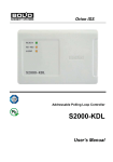
Orion ISS
Intrusion and Fire Alarm Panel
Signal-10
User’s Manual
This User’s Manual is intended to help for studying operability principles and maintenance of
Signal-10 Intrusion and Fire Alarm Panel of version 1.03.
Please read the instructions completely before connecting, operating, adjusting or maintaining
this product.
The following terms are used throughout the Manual:
Alarm Loop (or Loop, or LP): The electrical circuit with non-addressable fire or intrusion detectors
(or other non-addressable devices) included. Actuation of a single detector brought in an alarm
loop causes breaking of the loop as a whole, so the actuated detector can be located only with
the accuracy of the alarm loop.
Zone: A minimal part of a security and safety installation that can be monitored and controlled independently. Depending on the context, the term ‘zone’ can imply an alarm loop, an addressable
detector, a hardware component, and so on.
Partition: A set of zones that can be user controlled as a whole. As a rule, zones fall into partitions
depending on their location (e.g., one partition can involve all zones at one individual area)
Arm/Disarm means starting/cancellation monitoring of loop (zone, partition, system) conditions and
signaling alarms in controlled zones
Integration Time – a time interval during which sudden alterations of loop resistance are not considered as loop breaking, thus producing no alarms
Network Address (or Address): A unique number of the device (from 1 to 127) within the ISS Orion
local RS-485 network
Signal-10
Table of Contents
General ................................................................................................................................... 5
Specifications ........................................................................................................................ 9
Operation Principles ............................................................................................................ 13
Alarm Loops................................................................................................................................ 14
Alarm Loop Configuration Parameters .............................................................................. 14
Alarm Loop Types ............................................................................................................. 18
Smoke Two Threshold Alarm Loop (Type 1) .......................................................................... 19
Combined Fire Single Threshold Alarm Loop (Type 2) ......................................................... 20
Heat Two Threshold Alarm Loop (Type 3) ............................................................................. 21
Intrusion Alarm Loop (Type 4) ............................................................................................... 22
Intrusion Alarm Loop with Tamper Monitoring (Type 5)....................................................... 22
Auxiliary Alarm Loop (Type 6) ............................................................................................... 23
Entrance Alarm Loop (Type 7) ............................................................................................... 24
Panic Alarm Loop (Type 11) .................................................................................................. 25
Programmable Auxiliary Alarm Loop (Type 12) .................................................................... 25
Fire Threshold Addressable Alarm Loop (Type 14) ............................................................... 26
Alarm Integration Time ...................................................................................................... 29
Powering Detectors over Alarm Loops .............................................................................. 29
Relay Outputs ............................................................................................................................. 30
Local Output Control ......................................................................................................... 31
Centralized Output Control ................................................................................................ 32
Electronic Keys ........................................................................................................................... 36
User Keys .......................................................................................................................... 36
Master Keys ...................................................................................................................... 36
Operating Modes ........................................................................................................................ 37
Pre-Operation Mode .......................................................................................................... 37
Operation Mode ................................................................................................................. 37
Power Failure Mode .......................................................................................................... 38
Output Circuit Failure Mode .............................................................................................. 38
Master Key Programming Mode ........................................................................................ 38
User Key Programming Mode ........................................................................................... 38
Self-Diagnostic Mode ........................................................................................................ 39
Device Failure Mode ......................................................................................................... 39
Fire Alarms ................................................................................................................................. 40
Conventional Fire Alarm Systems ..................................................................................... 40
Addressable Fire Alarm Systems ...................................................................................... 41
Intrusion Alarms .......................................................................................................................... 43
General Intrusion Alarms ................................................................................................... 43
Intrusion and Detector’s Tamper Alarms ........................................................................... 44
Entrance Alarms ................................................................................................................ 45
Panic Alarms ..................................................................................................................... 46
Auxiliary Alarms .......................................................................................................................... 48
3
www.bolid.com
Orion ISS
Loop Status Light and Sound Indication......................................................................................51
Alarm Loop Arming and Disarming .............................................................................................53
Local Arming/Disarming .....................................................................................................53
Centralized Remote Arming/Disarming ..............................................................................53
Communications Between the Sighnal-10 and a Network Controller..........................................55
Transmitting Messages to a Network Controller ................................................................55
Installation ............................................................................................................................ 59
Standard Delivery ........................................................................................................................60
Safety Precautions ......................................................................................................................60
Signal-10 Mounting .....................................................................................................................60
Wiring the RS-485 Interface Line ................................................................................................62
Connecting External Devices to the Device Outputs...................................................................62
Connecting Alarm Loops .............................................................................................................64
Including Detectors into Fire Smoke Alarm Loops of the Type 1 .......................................64
Including Smoke and Heat Detectors into Alarm Loops of the Type 2...............................65
Including Heat Detectors into Alarm Loops of the Type 3 ..................................................65
Including Intrusion Detectors into Alarm Loops of the Type 4............................................65
Including Intrusion Detectors into Alarm Loops of the Type 5............................................66
Wiring Initiating Devices into Alarm Loops of the Type 14 .................................................66
Connecting Power Supplies ........................................................................................................66
Commissioning ............................................................................................................................67
Programming ........................................................................................................................ 69
Signal-10 System Settings ..........................................................................................................71
Alarm Loop Programming ...........................................................................................................74
Loop Type Adjusting ..........................................................................................................74
Other Loop Parameters Adjusting ......................................................................................76
Programming Outputs .................................................................................................................79
Key Programming........................................................................................................................82
Key Programming by Means of UProg.exe ........................................................................82
Add/Edit a Key ........................................................................................................................ 83
Delete Key ............................................................................................................................... 85
Operations with the List of Keys ............................................................................................. 85
Save Results ............................................................................................................................ 86
Programming of Keys by Hardware ...................................................................................86
Programming of a Master Key by Hardware ......................................................................... 86
Programming of User Keys by Hardware .............................................................................. 87
Maintenance ......................................................................................................................... 89
Signal-10 Operability Inspection..................................................................................................90
Testing the Signal-10 in Self-Diagnostic Mode ...........................................................................90
Alarm Loop Inspection.................................................................................................................91
Annex. Current Consumption Estimation .......................................................................... 93
www.bolid.com
4
Signal-10
General
GENERAL
5
www.bolid.com
Orion ISS
The Signal-10 Intrusion and Fire Alarm Panel (hereinafter referred to as the Signal-10 or the device)
is intended to be used in cooperation with an Orion network controller (an S2000М console or a personal computer with Orion Pro software installed) as a control and indicating equipment being part of
an
−
Intrusion and Panic Alarm System,
−
Fire Alarm and Extinguishing System,
−
Announcement and Evacuation Management System.
The Signal-10 provides monitoring for up to 10 alarm loops with included detectors and initiating devices. The ways to monitor for the alarm loops and the relevant parameters (“types” of the alarm
loops) are to be programmed while configuring the device individually for each alarm loop.
The Signal-10 also can operate in a standalone mode. In such case it works as single-component
control and indicating equipment (in an intrusion alarm system) which:
¾
Monitors up to 10 non-addressable alarm loops of the following types:
− Intrusion Alarm Loop (Type 4);
− Intrusion Alarm Loop with Tamper Monitoring (Type 5);
− Entrance Alarm Loop (Type 7);
− Panic Alarm Loop (Type 11);
− Auxiliary Alarm Loop (Type 6);
− Programmable Auxiliary Alarm Loop (Type 12)
¾
¾
¾
¾
Controls two relay outputs without monitoring connected circuits;
Controls two switch transistor outputs with monitoring connected circuits;
Indicates individual states of alarm loops and troubles by its 11 built-in LEDs;
Supports arming / disarming its alarm loops by means of electronic credentials (iButtons and
proximity cards) via the connected external reader;
¾
¾
Enables operating a group of its alarm loops simultaneously;
Provides storing in its memory up to 85 credentials along with their rights to operate alarm
loops;
¾
¾
Is powered by one or two unrelated external DC power supplies;
Is equipped with a tamper switch.
Being a part of an Orion ISS, in cooperation with the Orion network controller (an S2000М console or
a personal computer with Orion Pro software installed) the Signal-10 represents a combined control
and indicating device and managing device.
www.bolid.com
6
Signal-10
General
In spite of functions and features implemented in the standalone mode (listed above), in cooperation
with the network controller the Signal-10:
¾
Monitors up to 10 fire alarm loops
o Of non-addressable types, namely:
− Smoke Two Threshold Alarm Loop (with recognizing responses from one or two
detectors within the alarm loop), Type 1;
− Combined Fire Single Threshold Alarm Loop (both smoke and heat fire detectors can be
brought in the alarm loop), Type 2;
− Heat Two Threshold Alarm Loop, Type 3;
o or/and Fire Threshold Addressable Alarm Loops of the Type 14 each of which can monitor
up to 10 connected detectors such as DIP-34PA, S2000-IP-PA, and IPR 513-3PA;
¾
Transmits to the Orion system messages about such events as changing states of alarm
loops, attempts to arm / disarm alarm loops, accidental conditions, troubles of the alarm loops,
the relay outputs, power and so on;
¾
Supports centralized control of its outputs, that control being caused by events in the Orion
system, such as alarms in intrusion partitions, granting /rejecting access through access points
etc.;
¾
Supports arming / disarming its alarm loops by means of electronic credentials (iButtons or
cards) via any reader in the system;
¾
Supports arming / disarming its alarm loops by means of system push-button keypads or from
the network controller;
¾
Being requested by the network controller, translates the current values of resistance of the
alarm loops with connected detectors and initiating devices;
¾
Stores in its non-volatile memory up to 512 events which cannot be translated to the network
controller in case of a temporal communication loss.
Arming/disarming of alarm loops is implemented by using electronic keys which can be Dallas
iButtons (Touch Memory devices) or other identifiers with 1-Wire (µ-LAN) output interface. To read
electronic keys an external reader is to be connected to the relevant input of the Signal-10. The device provides indication of current partition conditions and results of requested operations by means
of two-color reader LED.
The keys have to be pre-programmed, that is enrolled either into the device memory (if alarm loops of
the device are armed/disarmed locally) or into the network database (under centralized control) along
with the rights to arm/disarms the particular loops of the device assigned to each key.
7
www.bolid.com
Orion ISS
The device can be powered by one or two (the main and the extra) power supplies providing 12 or 24
Volt of DC. It is strongly recommended to use Bolid manufactured battery backed power suppliers of
series RIP-12 or RIP-24.
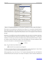
To program the Signal-10 device for adapting to particular user conditions and meeting specific user
needs the Orion device configuration tool, UProg.exe program, has to be used. The latest version of
the UProg Configuration Tool can be downloaded from the Bolid website at the address of
www.bolid.com. To program the device by means of the UProg, it should be connected to a PC with
UProg.exe installed via one of Bolid manufactured interface converters such as PI-GR, S2000-PI,
S2000-USB, or USB-RS485.
The Signal-10 is equipped with a tamper switch which provides generating tamper alarms while tamper conditions are changed and transmitting them to a network controller.
The Signal-10 Intrusion and Fire Alarm Panel is intended for indoor installation and round the clock
operation. The device is not suitable for operation in corrosive and dusty environments, as well as in
fire-hazardous or explosive areas.
www.bolid.com
8
Signal-10
Specifications
SPECIFICATIONS
9
www.bolid.com
Orion ISS
¾
Indicators (LEDs)
READY LED to indicate device condition and 10 status
indicators to indicate statuses of the device alarm loops
¾
Internal Sounder
Built-in
¾
Tamper Switch
Built-in
¾
Event Log Capacity
512 events
¾
RS-485 Communication Port
Yes
¾
Data Transmission
Half-duplex
Transmission Rate
9600 Bd
Power Supply
External 12 to 24 V DC.
Bolid manufactured RIP-12 or RIP-24 battery backed
power supplies are advisable 1
¾
¾
Input Voltage
Two inputs (main and backup)
Rated Voltage
10.2 V ÷ 28.4 V DC
Shutdown Voltage
9 V DC
Input Current
220 – 410 mА at 12 V supply voltage,
110 – 200 mА at 24 V supply voltage 2
¾
Pre-Operation Time
3 s maximum provided that at least 11 V steady voltage is
applied to one of power inputs
¾
External ID Reader
One Reader Input to connect an external reader of ID such
as Dallas Touch Memory devices (iButtons) and so on
Output Interface
Touch Memory (1-Wire, µ-LAN)
Reader LEDs
Two LEDs (Red + Green) controlled by logical
+5 V CMOS levels, with current values being restricted by
10 mA at direct connection
¾
ID Memory Capacity
Up to 85 ID codes
1
The input power voltage is commuted also to the device outputs SIR and LAM to provide power to external sound and light alarms. If the outputs are loaded close to maximum values, it is advisable to power
the Signal-10 device from 24 V power supplies
2
More precise values can be found at the Annex to this document, see page 93 of this Manual
www.bolid.com
10
Signal-10
¾
Specifications
Alarm Inputs
10 inputs to monitor alarm loops
Detectors to Be Included
Addressable initiating devices DIP-34PA, IPR513-3PA,
S2000-IP-PA (up to 10 to each alarm input), or
any conventional fire and intrusion detectors intended
to be powered by a DC power supply and having the
values of internal resistance at Fire mode:
No more than 2.7 kΩ for normally open detectors,
At least 3.2 kΩ for normally closed detectors
Max Wire Resistance
1 kΩ for intrusion alarm loops,
(without regard to termination resistor)
100 Ω for fire alarm loops
Min Leakage Resistance Between
20 kΩ for intrusion alarm loops,
Loop Wires or Between Each Wire
50 kΩ for fire alarm loops
and the Earth
Loop Voltage
22 V÷ 19 V if the termination resistor of 4.7 kΩ±5% is
brought to the loop and the value of consumed current
is 0 to 3 мА (provided that there are no more than 3
short-circuited loops simultaneously,
27 ± 0.5 V if the alarm loop is opened
¾
Max.Short-Circuited Loop Current
26.5 mА
Loop Ripple Voltage
20 mV max
Solid State Relay Outputs
2 outputs ALR1 and ALR2 with normally open contacts
intended to transmit alarms and troubles to Central
Stations
¾
Commuting Voltage & Current
170 V dc & 0.1 А; 130 V ac & 0.1 А
Transistor Outputs
2 outputs with the possibilities to supervise load circuits
for open and short failures; these outputs are intended
to connect external sound and light alarms
¾
Commuting Voltage & Current
28 V & 1 А
Load Circuit Supervision Current
3 mА max, the alarms being off
Load Circuit Protection
Resettable fuses
Operating Temperatures
From −30 °С to +50 °С
11
www.bolid.com
Orion ISS
¾
Relative Humidity
Up to 98% at +25 °С
¾
Ingress Protection Rating
IР20
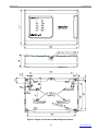
¾
Overall Dimensions
156х107х39 mm
¾
Weight
about 0.3 kg
¾
Average Lifetime
10 years
¾
Device Programming
By means of UProg.exe which is the tool for Orion system device configuration
¾
Connection to a PC
Over RS-485 interface bus via one of the Bolid manufactured
interface
converters
S2000-USB, or USB-RS485
www.bolid.com
12
PI-GR,
S2000-PI,
Signal-10
Operation Principles
OPERATION PRINCIPLES
13
www.bolid.com
Orion ISS
ALARM LOOPS
The Signal-10 device provides monitoring for up to ten alarm loops connected to its input contacts.
While operating with threshold detectors (opposite to operating with addressable threshold initiating
devices which will be described later), the device measures and analyses the effective resistance values of each the connected alarm loop. Depending on:
¾
¾
¾
The measured resistance value, and
Whether the loop is armed or disarmed, and
The algorithm the loop is programmed to be monitored (so called Loop Type)
the Signal-10 assigns this loop to a certain status such as ‘Norm’, ‘Failure’, ‘Alarm’ and so on.
Having analyzed the loop status, the Signal-10 device:
−
Indicates the loop status by the related built-in two-color status LED on the device cover
−
Emits a specified sound signal by means of the built-in sounder (not for all statuses)
−
Activates executive outputs (if programmed)
−
While operating as a part of an Orion security system, automatically transmits loop status altering to the Orion network controller
Any fire and intrusion detectors intended to be powered by DC supply can be brought into alarm loops
of the Signal-10, the detector internal resistance in Fire mode having to be:
−
No more than 2.7 kΩ for normally open detectors and
−
No more than 3.2 kΩ for normally closed detectors
Alarm Loop Configuration Parameters
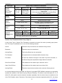
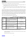
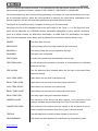
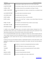
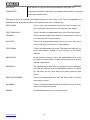
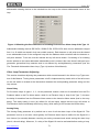
Table 1 shows a set of parameters which can be programmed for the Signal-10 device to define a
monitoring algorithm for each the alarm loop of the Signal-10.
The main configuration parameter of each the Signal-10 alarm loop is the Loop Type. This parameter
defines which way the alarm loop will be monitored for and which detectors can be included into this
loop. The Signal-10 supports 10 various types of alarm loops which will be described in details in the
next section.
The Arming Delay (Exit Delay) parameter defines the time (in seconds), starting from the moment of
the receiving the arming command, after elapsing of which the Signal-10 will really attempt to arm the
alarm loop. Non-zero Arming Delay values are typically used for Entrance Alarm Loops (of the Type 7).
Moreover, if one of the Signal-10 outputs is required to be activated before arming an alarm loop, for
example, to unset power of 4-wire detectors by means of the ‘Switch On for a Time Before Arming’ executive program, this alarm loop must obligatory have non-zero Arming Delay (see Relay Outputs section of this Manual).
www.bolid.com
14
Signal-10
Operation Principles
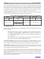
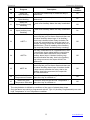
Table 1. Alarm Loops Configuration Parameters
Parameter
Description
Value Range
1 – Smoke Two Threshold
2 – Fire Combined
(Smoke + Heat)
Single Threshold
3 –Heat Two Threshold
4 – Intrusion
Loop Type
Defines
the tactics the alarm loop to be monitored for,
the kind of detectors to be included into the
alarm loop, and
statuses to be assigned to the alarm loop
5 – Intrusion With Tamper
Monitoring
(see Note on page 23)
6 – Auxiliary
7 – Entrance
11 – Panic
12 – Programmable
Auxiliary
14 – Fire Threshold
Addressable
From 1 to 254 s,
the ‘0’ value means ‘without a delay’
the ‘255’ value means
‘infinite delay’
Alarm Delay
The delay for switching between
Entrance Alarm and Intrusion Alarm statuses, or
Fire Prealarm and Fire Alarm statuses
Arming Delay
The delay between receiving the arming command and switching the loop to Armed mode
From 0 to 255 s
Auto Rearming
After Failing
Automatic switching from Arming Failed status
to Armed status when the alarm loop having
restored
On / Off
The time interval required for transient processes to be completed within the alarm loop after
powers resets. During this time the status of the
alarm loop will not be analyzed
From 1 to 63 s
The delay in seconds between having the related alarm loop (loops) broken and activating the
relay
From 0 to 255 s
Never Disarm
The alarm loop cannot be disarmed by any way
On / Off
Auto Arming
After Alarm
Automatic switching from the Intrusion Alarm,
Panic Alarm, or Fire Alarm status to the Arming
Delay status when the alarm loop has been
restored
On / Off
Disarmed Loop
Monitoring
The directive to transmit over RS-485 interface
messages about altering conditions (Norm/No
Norm) of the disarmed loop
On / Off
Loop Analysis Delay
Relay 1 (‘Alarm 1’)
Activation Delay
Relay 2 (‘Alarm 2’)
Activation Delay
Relay 3 (‘Siren’)
Activation Delay
Relay 4 (‘Lamp’)
Activation Delay
15
www.bolid.com
Orion ISS
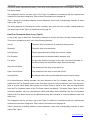
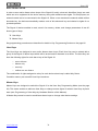
Parameter
Description
Value Range
Fire Loop
Requery
Prohibition
Being on, disables the function of repeated query for the loop condition for alarm loops of
Types 1 and 2
On / Off
300-ms Integration
Time
Being on, causes an intrusion alarm loop to
enter the Intrusion Alarm status if this one has
been broken for more than 300 ms
On / Off
10% Deviation
Blocking
Being on, causes an intrusion alarm loop not to
enter the Intrusion Alarm status if its resistance
value has been changed more than by 10%
within 255 s
On / Off
Relay 1 Control
Relay 2 Control
Relay 3 Control
On / Off
Enables controlling the relevant relay output in
relation with this alarm loop condition changing
Relay 4 Control
Related
Addressable
Detectors
On / Off
On / Off
On / Off
For alarm loops of the Type 14 matches the
addressable zones of these loops with installed
threshold addressable detector and call point
addresses
On / Off
The Alarm Delay parameter in case of Entrance alarm loop (Type 7) represents the time which is to
expire for the device to switch from Entrance Alarm status to the Intrusion Alarm status (that is, the Entry Delay). Its value is selected by such a way that it will be sufficient for a user to disarm the alarm loop
after its breaking (after entering the premises) without generating an alarm.
For fire alarm loops (of Types 1, 2, 3, 14) the Alarm Delay represents a timeout for switching from the
Fire Prealarm status to the Fire Alarm status. Alarm loops of Types 1, 3, and 14 (two threshold) can
also reach the Fire Alarm status if a second fire detector in the loop has actuated. If the value of an
Alarm Delay is equal to 255 s, it means that the alarm loop doesn’t switch to the Fire Alarm status by
time condition (infinite delay). In such a case alarm loops of the Types 1 and 3 can switch to the Fire
Alarm status only after actuating of a second detector in the loop, but an alarm loop of the Type 2 never
reaches the Fire Alarm status.
If, while arming an alarm loop, the alarm loop resistance is below a normal value, for example, an included smoke fire detector has actuated, the device automatically unsets the loop, that unsets its power
for 3 s. Loop Analysis Delay for an alarm loop of any type is a pause which is to expire since the power has been restored and until the loop condition will be analyzed. This delay enables including into
device alarm loops the detectors with a high worm-up time (or high damping time). If such the detectors
are included into an alarm loop, it is necessary to program the Loop Analysis Delay for this alarm loop
some more than the maximum worm-up time.
The minimum hardware delay value is 1 s. This value can be increased up to 63 s.
The Never Disarm parameter disables disarming the alarm loop by any way. Typically, this parameter
is set on for fire and intrusion alarm loops to avoid its accidental disarming. If the alarm loop has the
www.bolid.com
16
Signal-10
Operation Principles
Intrusion Alarm, or Panic Alarm, or Fire Prealarm, or Fire Alarm, or Arming Failed status, both arming
and disarming the alarm loop will lead to attempt to arm the loop.
If an alarm loop has had the Arming Failed status (that is, was broken in the moment of being armed
and the Auto Rearming After Failing attribute is set on for the alarm loop, the alarm loop will automatically be armed when its resistance comes back to a normal value and is kept normal for more than 3 s.
If an alarm loop has switched to the Intrusion Alarm, or Panic Alarm, or Fire Alarm status and the Auto
Arming After Alarm attribute is set on for the alarm loop, the loop will automatically be armed when its
resistance comes back to a normal value and is kept normal for more than the time interval equal to 15
times Alarm Delay values (in seconds).
The Disarmed Loop Monitoring parameter causes the Signal-10 to monitor the alarm loop also in the
Disarmed status. If the resistance of the loop is normal, the Signal-10 transmits a network controller a
READY TO ARM message, otherwise, if the loop is broken, a NOT READY TO ARM message is
transmitted. The integration time for the disarmed loop broken status is 300 ms, while to consider the
disarmed loop as being in norm the integration time is equal to the Alarm Delay value.
The Relay 1…4 Control parameters relates alarm loops to required relay outputs of the Signal-10. If
statuses of an alarm loop must affect on conditions of one or several device outputs, the relevant parameter for the alarm loop must be set on.
If any output of the Signal-10 must be activated by remote commands of a network controller (that is, in
case of centralized control), then the relevant control parameter for this output must be off for all the
alarm loops of the Signal-10.
If changing of alarm loop statuses must lead to switching of any relay output in accordance with an assigned executive program (see Relay Outputs section of this Manual), switching will be delayed for a
time given for the loop by а Relay 1…4 Activation Delay. For some particular executive programs
such as 9 (Lamp), 10 (Alarm Output), 13 (Fire Output), 14 (Trouble Output), 15 (Fire Lamp) и 16 (Alarm
Output 2), see Table 5, the Relay Activation Relay is ignored and the relay output is switched immediately after loop status changing.
The Fire Loop Requery Blocking parameter, being set on, disables the function of the repeated query
of the conditions of the alarm loops of Types 1 and 2 after a detector within the loop has actuated.
Thus, if the Fire Loop Requery Blocking is set on, actuating of a single fire detector within the alarm
loop will immediately switch the loop to the Fire Prealarm status.
The 300-ms Integration Time parameter enables to set the integration time for intrusion alarm loops
(of the Types 4, 5, 7, and 11). The value “On” corresponds to the integration time equal to 300 ms,
while the “Off” one corresponds to that equal to 70 ms. In order to decrease false alarms the integration
time of 70 ms must be selected only if it is strongly necessary.
The 10% Deviation Blocking parameter disables intrusion alarm loop’s analysis in case of sharp distinctions of loop resistance (more than by 10% from a steady-stated value) not skipping though out of
17
www.bolid.com
Orion ISS
the normal range. It is advisable to set this parameter on for such the alarm loops which involve detectors producing high voltage ripples in the alarm loop.
The Related Addressable Detectors parameters relates an alarm loop of the Type 14 (the threshold
addressable alarm loop) with the addresses of the already installed into the loop addressable detectors
or call points – see Fire Threshold Addressable Alarm Loop (Type 14) section of this Manual. If the addressable zone of an addressable detector or call point is not related to an alarm loop, this zone doesn’t
take part in generating of a generalized loop and is not affected by loop arming/disarming commands.
Alarm Loop Types
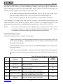
The main alarm loop configuration parameter which defines the way the controller considers the conditions of the alarm loop is the Loop Type. The Signal-10 supports 10 different types of alarm loops.
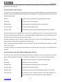
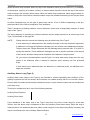
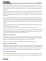
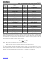
Table 2 shows how the current resistance values of alarm loops are considered by the Signal-10 device
to be different loop statuses depending on the current type of the alarm loop.
Table 2. Alarm Loop Resistance Values for Different Loop Statuses
Loop Type
Alarm Loop Conditions and Statuses
Short
Circuit
Type 1
Smoke
Two Threshold
Type 2
Fire
Combined
Single
Threshold
Type 3
Heat
Two Threshold
Type 4
Intrusion
www.bolid.com
Less than
100 Ω
Fire Alarm
(two or more
smoke detectors
have actuated)
Fire Prealarm
(a smoke
detector
has actuated)
From 150 Ω to
1.56* kΩ
From 1.1* kΩ to
1.8 kΩ
* Depends on the loop load current
Norm
Open Circuit
From 2.2 to
5.4 kΩ
More than 6.6 kΩ
Fire Prealarm/
Fire Alarm
(a heat detector
has actuated)
Open Circuit
Short
Circuit
Fire Prealarm/
Fire Alarm
(a smoke
detector
has actuated)
Norm
Less than
100 Ω
From 150 Ω to
1.8* kΩ
From 2.2 to
5.4 kΩ
Short
Circuit
Norm
Fire Prealarm
(a heat detector
has actuated)
Fire Alarm
(two or more
heat detectors
have actuated)
Open Circuit
Less than
1.8 kΩ
From 2.2 to
5.4 kΩ
From 6.6 to
11 kΩ
From 12.5 to
22.5 kΩ
More than 25 kΩ
From 6.6 to 14.4
More than 16 kΩ
kΩ
Norm
Intrusion Alarm
From 2.2 to 10 kΩ
Less than 1.8 kΩ, or more than 12 kΩ, or has jumped
by more than 10 %
18
Signal-10
Operation Principles
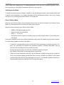
Loop Type
Type 5
Intrusion
With Tamper
Monitoring
Type 6
Auxiliary
Alarm Loop Conditions and Statuses
Norm
Intrusion Alarm
Detector Enclosure Tampering
From 2.2 to
5.4 kΩ
Less than
1.8 kΩ or more
than 6.6 kΩ
(if armed)
From 6.6 kΩ to 9.0 kΩ, or less than 100 Ω, or more
than 20 kΩ
(if the loop have the Disarmed, or Arming Delay,
or Arming Failed statuses)
Norm of Auxiliary alarm loop
Auxiliary alarm loop breaking
From 2.2 to 5.4 kΩ
Less than 1.8 kΩ or more than 6.6 kΩ
Norm
Entrance/Intrusion Alarm
From 2.2 to 5.4 kΩ
Less than 1.8 kΩ, or more than 6.6 kΩ,
or has jumped by more than 10 %
Norm
Silent Alarm (Attack)
From 2.2 to 5.4 kΩ
Less than 1.8 kΩ, or more than 6.6 kΩ, or has jumper by more than 10 %
Type 7
Entrance
Type 11
Panic
Status 1*
Type 12
Programmable
Auxiliary
Status 2*
Less than R1* from R1* to R2*
Status 3*
Status 4*
Status 5*
from R2* to R3*
from R3* to R4*
More than R4*
* − alarm loop statuses and threshold loop resistance values are user programmable
(see Auxiliary Alarms section of this Manual)
Smoke Two Threshold Alarm Loop (Type 1)
A loop of the Type 1 (Smoke Two Threshold) is intended to involve fire smoke (normally open) detectors. This loop is considered to be in one of the following statuses:
Armed
The alarm loop is monitored, its resistance being normal
Disarmed
The alarm loop is not monitored
Arming Delay
The Arming Delay has not yet expired
Fire Prealarm
A single detector has actuated within the alarm loop
Fire Alarm
At least two detectors brought in the alarm loop have actuated, or
the Alarm Delay has expired after single detector actuation
Short Circuit Failure
The resistance of the alarm loop is less than 100 Ω
Open Circuit Failure
The resistance of the alarm loop is more than 6 kΩ
Arming Failed
The alarm loop has been broken at the moment of being armed
An included detector having actuated, the Signal-10 generates FIRE SIGNAL message and repeatedly
queries the condition of the alarm loop by doing the following. The device unset loop power for 3 s. If
within 55 s after power reset the detector actuates repeatedly, then the alarm loop is considered to be
in the Fire Prealarm status. Otherwise, if the detector has not actuated repeatedly within 55 s, the alarm
19
www.bolid.com
Orion ISS
loop is considered to be in Armed status. The alarm loop can switch from the Fire Prealarm status to
the Fire Alarm status if a second detector included into this alarm loop has actuated, as well as the given Alarm Delay has expired. (If Alarm Delay is set with zero value, Fire Prealarm status will switch to
Fire Alarm status immediately.) The Alarm Delay value of 255 s (the maximum possible value) corresponds to unlimited timeout, such as switching from the Fire Prealarm status to the Fire Alarm status is
implemented only after actuating of another detector included into the alarm loop.
The integration time for an alarm loop of the Type 1 is defined in accordance with the requirements
mentioned in the Alarm Integration Time section of this Manual on the page 29.
Table 2 shows the matching between current resistance values and corresponding statuses of alarm
loops of the Type 1.
The wiring diagram for including fire smoke (normally open) detectors into alarm loops of the Type 1 is
presented on the page 64.
Combined Fire Single Threshold Alarm Loop (Type 2)
A loop of the Type 2 (Combined Fire Single Threshold) is intended to involve fire smoke (normally
open) and heat (normally closed) detectors. This loop is considered to be in one of the following statuses:
Armed
The alarm loop is monitored, its resistance being normal
Disarmed
The alarm loop is not monitored
Arming Delay
The programmed Arming Delay has not been expired
Fire Prealarm
Either activation of a heat detector or repeated activation of a smoke
detector is recognized within the loop
Fire Alarm
The Alarm Delay has expired after single detector actuation
Short Circuit Failure
The resistance of the loop is less than 100 Ω
Open Circuit Failure
The resistance of the loop is more than 16 KΩ
Arming Failed
An attempt to arm the loop has failed because the loop is broken
A heat detector having actuated, the loop switches to the Fire Prealarm status.
When a smoke detector has actuated, the Signal-10 generates a FIRE SIGNAL message and repeatedly queries condition of the loop (see above, for a loop 1). If detector actuation is confirmed, the loop
switches to the Fire Prealarm status.
The loop can switch from the Fire Prealarm status to the Fire Alarm status after expiring of the given
Alarm Delay. If the value of the given Alarm Delay equals to zero, then the loop will switch from the Fire
Prealarm status to the Fire Alarm status immediately. The Alarm Delay value of 255 s (maximum possiwww.bolid.com
20
Signal-10
Operation Principles
ble value) means unlimited time delay, so the loop never switches from the Fire Prealarm status to the
Fire Alarm status.
The integration time for an alarm loop of the Type 2 is defined in accordance with the requirements
mentioned in the Alarm Integration Time section of this Manual on the page 29.
Table 2 shows the matching between current resistance values and corresponding statuses of alarm
loops of the Type 2.
The wiring diagram for including fire smoke (normally open) and fire heat (normally closed) detectors
into alarm loops of the Type 2 is presented on the page 65.
Heat Two Threshold Alarm Loop (Type 3)
A loop of the Type 3 (Heat Two Threshold) is intended to involve fire heat (normally closed) detectors.
This loop is considered to be in one of the following statuses:
Armed
The alarm loop is monitored, its resistance being normal
Disarmed
The alarm loop is not monitored
Arming Delay
The programmed Arming Delay has not been expired
Fire Prealarm
A single detector has actuated within the alarm loop
Fire Alarm
At least two detectors brought in the alarm loop have actuated, or
the Alarm Delay has expired after single detector actuation
Short Circuit Failure
The resistance of the loop is less than 2 kΩ
Open Circuit Failure
The resistance of the loop is more than 25 KΩ
Arming Failed
An attempt to arm the loop has failed because the loop is broken
An included detector having actuated, the loop switches to the Fire Prealarm status. The loop can
switch from the Fire Prealarm status to the Fire Alarm status if a second detector in the loop has actuated, or a given Alarm Delay has expired. If the Alarm Delay is equal to zero, then the loop switches
from the Fire Prealarm status to the Fire Alarm status immediately. The Alarm Delay value of 255 s
(maximum possible value) is considered as infinite time delay, when switching from the Fire Prealarm
status to the Fire Alarm status can be implemented only after actuation of a second detector within this
alarm loop.
The integration time for an alarm loop of the Type 3 is defined in accordance with the requirements
mentioned in the Alarm Integration Time section of this Manual on the page 29.
Table 2 shows the matching between current resistance values and corresponding statuses of alarm
loops of the Type 3.
21
www.bolid.com
Orion ISS
The wiring diagram for including fire heat (normally closed) detectors into alarm loops of the Type 3 is
presented on the page 65.
Intrusion Alarm Loop (Type 4)
A loop of the Type 4 (Intrusion) is intended to involve any intrusion detectors, both normally open and
normally closed, and powered either over the loop or separately. This loop is considered to be in one of
the following statuses:
Armed
The alarm loop is monitored, its resistance being normal
Disarmed
The alarm loop is not monitored
Arming Delay
The programmed Arming Delay has not yet expired
Intrusion Alarm
The alarm loop has been broken
Arming Failed
An attempt to arm the loop has failed because the loop is broken
An Intrusion alarm loop is considered to be broken if its resistance goes out of normal range as well as
jumps by more than (provided that the 10% Deviation Blocking parameter is set off). Breaking an intrusion loop causes it to enter the Intrusion Alarm status.
An alarm integration time for this type of alarm loops can be 70 ms or 300 ms depending on the programmed value of the 300-ms Integration Time parameter.
Table 2 shows the matching between current resistance values and corresponding statuses of alarm
loops of the Type 4.
The wiring diagram for including intrusion detectors into alarm loops of the Type 4 is presented on the
page 65.
Intrusion Alarm Loop with Tamper Monitoring (Type 5)
A loop of the Type 5 (Intrusion with Tamper Monitoring) is intended to involve a single intrusion detector
and the tamper switch of this detector. This loop is considered to be in one of the following statuses:
Armed
The alarm loop is monitored, its resistance being normal
Disarmed
The alarm loop is not monitored
Arming Delay
The programmed Arming Delay has not yet expired
Intrusion Alarm
The alarm loop has been broken
Arming Failed
An attempt to arm the loop has failed because the loop is broken
Tamper Alarm
The enclosure of the disarmed detector has been tampered, or
short circuit failure of the disarmed loop has been detected
www.bolid.com
22
Signal-10
Operation Principles
When the alarm loop is armed, either any skip of the resistance value (by more than 10%), or actuation
of the detector (opening of its alarm contact), or tamper switch actuation causes the loop to be considered as being in the Intrusion Alarm status. When the alarm loop is disarmed, either tamper switch actuation or loop short circuit failure causes the alarm loop to be considered as being in the Tamper Alarm
status.
An alarm integration time for this type of alarm loops can be 70 ms or 300 ms depending on the programmed value of the 300-ms Integration Time parameter.
Table 2 shows the matching between current resistance values and corresponding statuses of alarm
loops of the Type 5.
The wiring diagram for including an intrusion detectors and its tamper switch into an alarm loop of the
Type 5 is presented on the page 66.
NOTE:
Please take into account the following using an alarm loop of the Type 5.
If such alarm loop is disarmed when the detector brought in the loop has been responded,
in addition to receiving the Disarmed message you can receive some additional messages:
Tamper Alarm and Tamper Restored, the last message being received after 15 s since restoring the detector. These additional messages are due to specific operation of the device
of this version and don’t show actual conditions of the detector’s tamper switch.
So, you are not recommended to use the Type 5 in cases when alarm loops are to be supposed to be disarmed after a detector’s response (after entering into the protected
area).
If such alarm loop is disarmed when the detector is in quiescent mode, no additional messages are received.
Auxiliary Alarm Loop (Type 6)
Auxiliary alarm loops (loops of the Type 6) are intended to monitor operability and conditions of firefighting equipment as well as sensors and indicators not related directly with fire or intrusion alarms.
Devices with dry contact (both normally closed and open) or open collector outputs can be included into
such alarm loop.
This loop is considered to be in one of the following statuses:
Auxiliary Zone Restored
Auxiliary Zone Alarm
If the resistance of the alarm loop of the Type 6 has been out of the normal range for more than
300 ms, then the alarm loop is considered to be in the Auxiliary Zone Alarm status. When the loop is
restored (that is, its resistance has been within normal range for more than Arming Delay seconds), the
loop is considered to be in the Auxiliary Restored Status.
23
www.bolid.com
Orion ISS
Table 2 shows the matching between current resistance values and corresponding statuses of alarm
loops of the Type 6.
An auxiliary alarm loop is always monitored; it cannot be blocked or disarmed. If the arming command
addressed to this loop is received, the device responds with the message about its current status.
When a status of an Auxiliary alarm loop has changed the Signal-10 transmits a relevant message to a
network controller. The events related to Auxiliary alarm loop are not stored in the Signal-10 nonvolatile memory. Thus, if a status of an Auxiliary alarm loop has changed several times during communication loss, after communication having restored the network controller receives either a single last
message or no message if the current status of the loop is just like as the last transmitted status.
If an Auxiliary alarm loop is related to a Signal-10 relay output, then its breaking locks starting the relay
in accordance with executive programs ##1 – 8 (general-purpose), #11 (ASPT), #2 (Siren), #33
(ASPT-1), #34 (ASPT-A), #35 (ASPT-A1), see Table 5. This functionality is suitable, for example, to
lock automatic starting of gas firefighting installations when a door in protected premises is open.
All normally closed and normally open detectors and other devices with dry contact outputs are included into Auxiliary alarm loops similarly to that how intrusion detectors are included to alarm loops of the
Type 4 (see the page 65).
Entrance Alarm Loop (Type 7)
A loop of the Type 7 (Entrance) is intended to involve any intrusion detectors, both normally open and
normally closed, and powered either over the loop or separately. This loop is considered to be in one of
the following statuses:
Armed
The alarm loop is monitored, its resistance being normal
Disarmed
The alarm loop is not monitored
Arming Delay
The programmed Arming Delay has not yet expired
Entrance Alarm
The alarm loop has been broken
Intrusion Alarm
Since breaking of the alarm loop the time of given Alarm Delay has
been expired
Arming Failed
An attempt to arm the loop has failed because the loop is broken
An Entrance alarm loop is operated similarly to an Intrusion alarm loop, except this loop switches to the
Entrance Alarm status immediately after its breaking. Then, if this alarm loop is not disarmed or armed
until the Alarm Delay has been expired, the loop switches to the Intrusion Alarm status.
While the alarm loop is being in the Entrance Alarm status, no relay controlled in accordance with one
of the general-purposed executive programs (#1 – #8) or Siren program (# 12) is activated.
www.bolid.com
24
Signal-10
Operation Principles
An alarm integration time for this type of alarm loops can be 70 ms or 300 ms depending on the programmed value of the 300-ms Integration Time parameter.
Table 2 shows the matching between current resistance values and corresponding statuses of alarm
loops of the Type 7.
The wiring diagram for including intrusion detectors into an alarm loop of the Type 7 is similar to that
presented on the page 65.
Panic Alarm Loop (Type 11)
All kinds of normally closed and normally open panic buttons, pedals and so on can be brought into a
Panic alarm loop (Type 11). This loop is considered to be in one of the following statuses:
Armed
The alarm loop is monitored, its resistance being normal
Disarmed
The alarm loop is not monitored
Arming Delay
The programmed Arming Delay has not yet expired
Panic Alarm
Breaking the loop has been detected
Arming Failed
An attempt to arm the loop has failed because the loop is broken
A Panic alarm loop is operated similarly to an Intrusion alarm loop, except this loop switches to the Panic Alarm status after it has been broken.
The Panic Alarm status is indicated only by the relevant Signal-10 LED and can initiate only that related
relay which is programmed to operate in accordance with Alarm Output 1 (#10) or Alarm Output 2 (#16)
executive programs (the relay contacts being opened). The internal sounder of the Signal-10 also is not
activated upon Panic Alarm.
An alarm integration time for this type of alarm loops can be 70 ms or 300 ms depending on the programmed value of the 300-ms Integration Time parameter.
Table 2 shows the matching between current resistance values and corresponding statuses of alarm
loops of the Type 11.
The wiring diagram for including panic buttons into an alarm loop of the Type 11 is similar to that presented on the page 65.
Programmable Auxiliary Alarm Loop (Type 12)
This type of loop monitoring methods can be used to monitor the conditions of various equipment and
detectors, including those which are not related directly with fire and intrusion alarms. Any detectors or
devices with dry contact or open collector outputs can be included into an alarm loop of the Type 12.
25
www.bolid.com
Orion ISS
A Programmable Auxiliary alarm loop can be in one of five different statuses which match each to its
own resistance range. These statuses and resistance values matched with them are user programmable. Accordingly, if a device can be in one of some different conditions and has several output contacts,
this device can be monitored by means of a single alarm loop. In such a case the output contact of the
device must be included into the alarm loop along with different additional or shunt resistors. By such a
manner the loop can be monitored for short and open failures.
Sound and light indication of the Signal-10 as well as the way this loop impacts on a related relay (that
is, the executive program assigned with the relay) are defined by the statuses this loop can reach.
Table 7 displays the list of statuses which can be programmed for an alarm loop of the Type 12, while
Table 5 shows the list of available executive programs taking into account different loop statuses.
The switching between statuses of a Programmable Auxiliary alarm loop is defined only by changing its
resistance and is not affected by any other loop parameters or network controller commands. The integration time for switching between statuses is generally equal to 300 ms. But if an alarm loop of the
Type 12 has entered such status as Armed, Disarmed, Auxiliary Zone Restored, or any other “… Restored”, the integration time for this status is equal to a programmed Arming Delay value.
A Programmable Auxiliary alarm loop is always monitored and cannot be blocked or disarmed. If the
arming command addressed to this loop is received, the device responds with the message about its
current status.
When the statuses of alarm loops of the Types 12 are changed the Signal-10 transmits the network
controller relevant messages. The events due to Programmable Auxiliary alarm loop are not stored in
the nonvolatile device memory similarly to loops of the Type 6.
Fire Threshold Addressable Alarm Loop (Type 14)
The Signal-10 supports operating with addressable detectors DIP-34PA and S2000-IP-PA in threshold
addressable mode as well as IPR513-3PA manual call points. To implement this, special Fire Threshold
Addressable alarm loops (loops of the Type 14) are intended. Up to ten DIP-34PA, S2000-IP-PA, or
IPR513-3PA can be included into such the alarm loop, thus enabling to build up to 100 addressable
zones based on a single Signal-10 device. The Signal-10 periodically polls connected detectors providing monitoring its operability and indication of malfunctioning or activated detectors. A response time of
each detector doesn’t exceed 10 s.
NOTE:
Statuses of each addressable zone of each loop of the Type 14 (each detector or call
point connected to the Signal-10) can be displayed separately only by a network controller. Thus, an addressable system can be fully implemented if the Signal-10 cooperates
with the network controller.
Each threshold addressable detector or call point included into an alarm loop of the Type 14 is considered as an additional addressable zone of the Signal-10. Each alarm loop can include up to 10 addressable zones which numbers range from 20 to 119. The digital number of a Signal-10 addressable
www.bolid.com
26
Signal-10
Operation Principles
zone is formed by adding the own detector or call point address (ranged from 1 to 10) to 10 times the
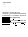
number of the loop incremented by one, so that:
Detectors connected to the contact
LP1 are assigned to addressable zones 20-29
LP2
⎯
30-39
LP3
⎯
40-49
LP4
⎯
50-59
LP5
⎯
60-69
LP6
⎯
70-79
LP7
⎯
80-89
LP8
⎯
90-99
LP9
⎯
100-109
LP10
⎯
110-119
No threshold addressable detectors or call points with the same own address can be
NOTE:
included into the same fire loop of the Type 14
The Signal-10 recognizes the following messages/conditions responded by addressable devices:
¾
¾
¾
¾
¾
¾
¾
Norm
Dusty, Service Required
Trouble
Fire
Manual Fire Alarm
Test
Isolated
A current condition of an alarm loop of the Type 14 is formed as a generalized condition of those addressable zones which are involved into this loop and matched with this loop by the given Related Addressable Detectors setting (see Alarm Loop Configuration Parameters section of this Manual). The
generalized condition of a loop of the Type 14 is defined as the most priority condition of all the addressable zones.
Following are all possible generalized conditions of a threshold addressable loop in the order of priority:
Fire Alarm
Two or more loop addressable zones have the Fire Alarm status, or the Alarm Delay given for this loop has been expired
Fire Prealarm
There is at least one addressable zone in the Fire Alarm status
Trouble
There is an addressable zone with the Trouble status, and there
is no zone with the Fire Alarm status
Isolated
There is an isolated addressable zone in the loop, while there
are no zones with Fire Alarm or Trouble statuses
27
www.bolid.com
Fire Signal
Orion ISS
There is an addressable zone with Test status and there are no
zones with Isolated, Trouble, or Fire Prealarm, or Fire Alarm
statuses
Arming Failed
At the moment of arming, one of the addressable zones of the
loop has a not Norm status, no other zones having more priority
statuses (said above)
Arming Delay
The transient status when after an attempt to arm an addressable zone the response from the addressable detector is waiting
for, and there are no zones with more priority statuses (said
above)
Dusty Sensor,
There is an addressable zone with the Dusty status, all other
Service Required
zones being in Norm
Disarmed
There is a disarmed addressable zone within the loop, all other
zones of the loop being armed
Armed
All addressable zones are in norm and armed
If a Fire condition has been detected for an addressable zone of a fire threshold addressable alarm
loop, this loop switches to the Fire Prealarm status. If Fire conditions have been detected for two different addressable zones of a loop, the loop switches to the Fire Alarm status. The loop also can switch
from the Fire Prealarm to Fire Alarm status after the programmed Alarm Delay having expired. If the
Alarm Delay is set to zero for this loop, the loop switches to the Fire Alarm status after a single detector
having actuated. If the Alarm Delay is set to 255 (infinite delay), the loop can switch to the Fire Alarm
status only after two detectors having actuated.
If the Signal-10 has no response from an addressable detector within 10 s, the Isolated status is assigned to its addressable zone. In such a case the function of breaking the loop to remove the detector
from its mounting base can be avoided and all other detectors in the loop keep their operability. No termination resistor is included into a fire threshold addressable alarm loop. The loop can be of any topology such as a bus, a ring, a star, or any hybrid topology.
While programming the Signal-10, it is possible to specify in advance the addresses of those detectors
which will be included into this threshold addressable alarm loop. It is implemented by the Related Addressable Devices parameter setting. If the matching an addressable zone to a particular alarm loop is
missed, then this zone is not considered when a generalized status of the alarm loop is formed and is
not affected by arming/disarming commands while the loop is armed/disarmed.
www.bolid.com
28
Signal-10
Operation Principles
Alarm Integration Time
The time interval, during which short-time loop resistance changes are not considered as its breaking
and don’t lead to any alarms (that is, the Alarm Integration Time), is equal to or less than:
−
50 ms for an intrusion alarm loop if the 300-ms Integration Time parameter is set off for this
loop
−
250 ms for other alarm loops and those intrusion alarm loops for which the 300-ms Integration Time parameter is on
The time interval, after expiration of which resistance changes of a loop are considered as its breaking
and cause the Signal-10 to generate alarms, is equal or more than:
−
70 ms for an intrusion alarm loop if the 300-ms Integration Time parameter is set off for this
loop
−
300 ms for an intrusion alarm loop or Auxiliary alarm loop if the 300-ms Integration Time parameter is set on for this loop
For alarm loops of the Types 1, 2, 3 breaking the loop causing the device to generate an alarm can
lasts from 300 ms to 3 s depending on transient processes occurring within the loop. If high capacity
detectors are included into the alarm loop, the Alarm Integration Time increases inversely to transient
process rate. The minimum loop voltage change rate corresponding to maximum Alarm Integration
Time is 0.5 V/s.
Powering Detectors over Alarm Loops
The Signal-10 supplies power over alarm loops to two-wire fire and intrusion detectors. The number of
detectors to be included in a single alarm loop is calculated by formula:
N = Im / i , where:
N is the number of detectors in the alarm loop
Im is the maximum load current
Im = 3 mА for alarm loops of Types 1, 4, 6, 7, 11, 12 and Im = 1.2 mА for alarm loops of Type 2
i is the current in mA consumed by a detector in quiescent mode
If an alarm loop of the Type 1 (fire smoke) is in use, fire detectors must keep their operability upon lowering the
voltage until 12 V.
29
www.bolid.com
Orion ISS
RELAY OUTPUTS
The Signal-10 device is equipped with four executive outputs, among them
¾
Two solid state relays ALR1 and ALR2 with normally open contacts, galvanic isolation, and
switching capacity of 170 V dc / 0.1А or 130 V ac / 0.1А, and
¾
Two transistor outputs SIR and LAM with output switching capacity of 28V/1А which can be
monitored for load circuit troubles and provide overcurrent protection by means of resettable
fuses
The SIR and LAM outputs are usually used to connect external sound and light alarms indicating
alarms and troubles. Outputs ALR1 and ALR2 are intended for separate transmission of fire alarms and
troubles in fire safety systems, or for transmission fire and intrusion alarms to central guard stations,
central monitoring stations, fire brigades, and so on. Optionally the relay outputs can be adapted to
meet individual user requirements, for example, to unset power of four wire detectors before its will be
armed, or to turn on/off various technical equipment (such as heaters, coolers, ventilators, air conditioners, etc.) in case of alarm loops of Type 12 status altering.
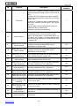
Table 3 shows the programmable parameters of Signal-10 outputs.
Table 3. Signal-10 Outputs Configuration Parameters
Parameter
Description
Value Range
Executive
Program
Defines the initial relay on/off condition and
the way the output will be controlled depending on the status of the alarm loops related
with this output
1 ... 37
Relay
Activation Time
Defines the time interval for which the relay
will be switched on/off if the assigned executive program implies the limited activation
time
0 s to 8192 s
(up to 2 hours 16 minutes 32s)
in increments of 0.125 s
Relay ON/OFF
Events
Enables/disables event transmissions in case
of output on/off condition altering in order to
display on system indicator modules or to log
these events in system database
On / Off
Monitor For
Defines the load circuit monitoring tactics for
outputs SIR (the relay 3) and LAM
(the relay 4)
1 – Without Monitoring
2 – Open Failure
3 – Short Failure
4 – Open and Short Failure
The Signal-10 outputs ALR1, ALR2, SIR, and LAM can be controlled in two ways:
−
Locally in accordance with an assigned executive program depending on statuses of related
alarm loops (see below)
−
Remotely by network controller commands
www.bolid.com
30
Signal-10
Operation Principles
The Monitor For parameter for outputs SIR and LAM defines the kinds of troubles of external device
circuits connected to these outputs which will be monitored for during Signal-10 operating. The failures
such as open circuit failures, short circuit failures, or both open and short failures will be monitored
without regard to is the relay output switched on or off. Setting this parameter to the value Without Monitoring disables monitoring for troubles of the SIR or LAM output circuit. Table 4 shows how the Signal10 considered the values of load circuit resistances to match the various circuit conditions.
The Relay ON/OFF Events parameter can be set on individually for each relay output. If the parameter
is set on then output condition altering is transmitted to a network controller.
Table 4. Output Circuit Conditions Depending on Effective Loading Resistance
Norm
Output
is on
Open Circuit
Output is
off
26 Ω to 10 kΩ
Output
is on
Short Circuit
Output is off
More than 12 kΩ
(upon supply voltage 12 V)
More than 25 kΩ
(upon supply voltage 24V)
More than 10 kΩ
Output
is on
Output is off
Less than 24 Ω
Local Output Control
In order to control automatically a device output depending on alarm loop condition (that is, local control) do the following:
−
While programming the alarm loop (loops), assign this loop (these loops) to the required relay by means of the relevant Relay … Control parameter and define if necessary the required Relay Activation Delay value (see the Alarm Loop Configuration Parameters Section of this Manual)
−
While programming the device outputs, assign this relay output to a suitable Executive Programs and give if necessary a suitable Relay Activation Time
An Executive Program defines the method the relay output will be controlled depending on current
status of the alarm loops related with the relay output and the initial condition of the relay after powering-on the Signal-10. Table 5 describes all available executive programs for the Signal-10 device.
A Relay Activation Time gives the time interval the relay will be activated for (switched on or off) if the
assigned executive program implies the limited activation time. The maximum time interval the relay
can be activated for is 8192s, that is 65535 intervals each of 0.125s.
For all the executive programs except #9, #10, #13, #14, #15, #16 (see Table 5), switching the relay
output on (off) upon the alarm loop status changing can be delayed for the time given by the relevant
Relay Activation Delay value for each alarm loop. Therefore, a relay output can be activated at different times depending on the particular alarm loop which status changing switches the relay and Relay
Activation Delay value specified for this loop.
31
www.bolid.com
Orion ISS
For executive programs #1 – #8 (general purpose programs), #11 (ASPT), #12 (Siren), #33 (ASPT-1),
#34 (ASPT-A), #35 (ASPT-A1) in case of breaking an Auxiliary alarm loop (of Type 6) related with an
output, switching this output from other related alarm loops is blocked. If upon the recovering of the
Auxiliary loop the conditions for switching the relay remains then:
−
for the executive programs with unlimited activation time (#1, #2, #5, #6) as well as programs #12 (ASPT) and #33 (ASPT-1) the relay output will be switched again, but
−
for the executive programs #3, #4, #7, #8, #34, #35 the output will NOT be switched
Thus, breaking of an Auxiliary alarm loop blocks an execution of the general purpose programs with
unlimited activation time as well as the programs ASPT and ASPT-1, and cancels the execution of the
general purpose programs with a restricted activation time as well as Siren, ASPT-A, ASPT-A1.
Local control of relay outputs is more significant than centralized control. That is, if a re-
NOTE:
lay output is related to an alarm loop status in the device settings then remote control
commands of a network controller over RS-485 interface will be ignored.
Centralized Output Control
To enable centralized control for a Signal-10 relay output:
−
In alarm loop settings, break an association between the output and any alarm loop of the
device (that is, the Relay … Control parameters for this output must be set OFF for all the
alarm loops of the Signal-10
−
In output settings, assign this relay output to any Executive Program with a suitable initial
relay on/off condition
−
In the network controller database, assign the output with relevant Orion system partitions
and give a required executive program along with a proper activation time and activation delay.
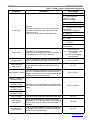
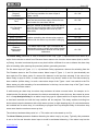
Table 5. Executive Programs for Relay Outputs
№
Program
0
Remote Control
1
Description
Initial
Condition
The relay is controlled only remotely
Off
Switch On
The relay is switched on if there is an Intrusion
Alarm or Fire Alarm
Off
2
Switch Off
The relay is switched off if there is an Intrusion
Alarm or Fire Alarm
On
3
Switch On for a Time
The relay is switched on for a specified time if
there is an Intrusion Alarm or Fire Alarm
Off
4
Switch Off for a Time
The relay is switched off for a specified time if
there is an Intrusion Alarm or Fire Alarm
On
5
Blink From Off
Condition
The relay is switched on/off once per second if
there is an Intrusion Alarm or Fire Alarm
Off
www.bolid.com
32
Signal-10
Operation Principles
№
Program
6
Blink From On
Condition
7
8
Description
Initial
Condition
The relay is switched on/off once per second if
there is an Intrusion Alarm or Fire Alarm
On
Blink for a Time From
Off Condition
The relay is switched on/off once per second for a
specified time if there is an Intrusion Alarm or Fire
Alarm
Off
Blink for a Time From
On Condition
The relay is switched on/off once per second for a
specified time if there is an Intrusion Alarm or Fire
Alarm
On
9
Lamp
In case of a Fire Alarm the relay is switched on/off
alternately twice per second
In case of a Fire Prealarm the relay is switched on
for a short time every second
In case of an Intrusion Alarm, or Entrance Alarm,
or Arming Failed the relay is switches on/off alternately once per second
In case of a Trouble the relay is switched on for a
short time once per two seconds
If an alarm loop is armed the relay is switched on
If all alarm loops are disarmed the relay is
switched off
*
10
Alarm Output 1
If all the alarm loops related with the relay are
armed then the relay is switched on, otherwise the
relay is switched off
ASPT
The relay is switched on for a given time if two or
more alarm loops related with the relay have Fire
Alarm status and there are no Auxiliary loops broken. The broken Auxiliary loop will block switching
on. If the Auxiliary loop is broken while the Relay
Activation Delay has not yet expired then, after
recovering of the loop, the relay output will be
switched on for a specified time. (That is, breaking
of the Auxiliary loop temporary blocks activation
delay counting.)
Off
12
Siren
In case of a Fire Alarm the relay is switched on/off
for a specified time in mode ‘On for 1.5s and Off
for .5s’
In case of a Fire Prealarm the relay is switched
on/off for a specified time in mode ‘On for .5s and
Off for 1.5s’
In case of an Intrusion Alarm the relay is switched
on for a specified time
Otherwise the relay is off
Off
13
Fire Output
If the related loop has Fire Alarm or Fire Prealarm
status then the relay is switched on, else the relay
is switched off (open)
*
14
Trouble Output
If there are related alarm loops having Trouble,
Arming Failed, or Disarmed status, the relay is
switched off. Otherwise the relay is switched on
*
11
33
*
www.bolid.com
Orion ISS
Program
Description
Initial
Condition
Fire Lamp
In case of a Fire Alarm the relay is switched on/off
twice per second in mode ‘On for .25s and Off for
.25s’
In case of a Fire Prealarm the relay is switched
on/off once per second in mode ‘On for .25s and
Off for .75s’
In case of a Trouble the relay is switched on/off
once per 2 seconds in mode ‘On for .25s and Off
for 1.75s’
If all the alarm loops related with the relay are
armed the relay is switched on
Otherwise, the relay is switched off
*
Alarm Output 2
If all the alarm loops related to the relay are armed
or disarmed (that is, there is neither Intruder
Alarm, nor Silent Alarm, nor Entrance Alarm, nor
Fire Alarm, nor Trouble, nor Arming Failed condition) the relay is switched on, otherwise the relay
is switches off
*
№
15
16
17
If the related alarm loop is being armed (the ArmSwitch On For a Time
ing Delay has not yet expired) the relay is
Before Arming
switched on for a given time
Off
18
If the related alarm loop is being armed (the ArmSwitch Off For a Time
ing Delay has not yet expired) the relay is
Before Arming
switched off for a given time
On
19
Switch On For a Time If any related alarm loop has just been armed the
Upon Arming
relay is switched on for a given time
Off
20
Switch Off For a Time If any related alarm loop has just been armed the
Upon Arming
relay is switched off for a given time
On
21
Switch On For a Time If any related alarm loop has just been disarmed
Upon Disarming
the relay is switched on for a given time
Off
22
Switch Off For a Time If any related alarm loop has just been disarmed
Upon Disarming
the relay is switched off for a given time
On
23
Switch On For a Time If arming of any related alarm loop has just failed
When Arming Failed the relay is switched on for a given time
Off
24
Switch Off For a Time If arming of any related alarm loop has just failed
When Arming Failed the relay is switched off for a given time
On
25
Switch On for a Time
Upon Auxiliary Loop
Breaking
If there is an Auxiliary Alarm the relay is switched
on for a given time
Off
26
Switch Off for a Time
Upon Auxiliary Loop
Breaking
If there is an Auxiliary Alarm the relay is switched
off for a given time
On
27
Switch On
Upon Disarming
If at least one related loop is disarmed the relay is
switched on
Off
28
Switch Off
Upon Disarming
If at least one related loop is disarmed the relay is
switched off
On
www.bolid.com
34
Signal-10
Operation Principles
Program
29
Switch On
Upon Arming
If at least one related loop is armed the relay is
switched on
Off
30
Switch Off
Upon Arming
If at least one related loop is armed the relay is
switched off
On
31
Switch On
Upon Auxiliary Loop
Breaking
In case of an Auxiliary Alarm the relay is switched
on
Off
32
Switch Off
Upon Auxiliary Loop
Breaking
In case of an Auxiliary Alarm the relay is switched
off
On
ASPT-1
The relay is switched on for a specified time if the
alarm loop has got Fire Alarm status and there are
no broken Auxiliary alarm loops. If an Auxiliary
alarm loop is broken before Relay Activation Delay has not yet expired then, when the loop is recovered, the relay output will be switched on for a
specified time. (That is, breaking of the Auxiliary
loop temporary blocks activation delay counting.)
Off
ASPT-А
The relay is switched on for a specified time if two
or more alarm loops related with the output have
got Fire Alarm status and there are no broken
Auxiliary alarm loops. A broken Auxiliary loop
cancels activation the relay, that is, the Auxiliary
loop being recovered, the output will NOT be
switched on
Off
ASPT-А1
The relay is switched on for a specified time if the
alarm loop has got Fire Alarm status and there are
no broken Auxiliary alarm loops. A broken Auxiliary loop cancels activation the relay, that is, the
Auxiliary loop being recovered, the output will
NOT be switched on
Off
33
34
35
Description
Initial
Condition
№
36
Switch On Upon
If the alarm loop has got the High Temperature **
Temperature Increase status the relay is switched on
Off
37
Switch On Upon
If the alarm loop has got the Low Temperature **
Temperature Decrease status the relay is switched on
Off
NOTES:
* The relay behavior is defined by conditions of the group of related alarm loops
** Only that alarm loop which is programmed with the Type 12 (Auxiliary Programmable) can enter
High Temperature or Low Temperature condition
35
www.bolid.com
Orion ISS
ELECTRONIC KEYS
In order to arm and/or disarm alarm loops of the Signal-10 locally, electronic identifiers (keys) are used
which are to be registered in the device memory along with related access rights. For this purpose, an
external reader has to be connected to the Signal-10. When a user touches the external reader with an
electronic key, the device automatically reads a code of this electronic key and checks its rights for requested operation.
The Signal-10 device enables to read, store in its memory, delete, and change parameters of two different types of keys:
¾
¾
User Keys
Master Keys
Key programming procedures are described in details in Key Programming Section on the page 82.
User Keys
The User Keys are designed to arm and/or disarm alarm loops. Each User Key can be related with a
group of the Signal-10 alarm loops which will be armed and/or disarmed as a whole. The User Key can
have the following rights for each alarm loop of the Signal-10:
― arm or disarm
― disarm only
― arm only
― neither arm nor disarm
The combination of rights assigned to a key for each device alarm loop is called Key Status.
Controller memory can store 85 User Keys maximum.
Master Keys
Master Keys are designed to switch the Signal-10 to the User Key Programming Mode (see the page
38). This mode enables to add new User Keys or change access rights of existent User Keys by hardware (see Programming of User Keys by Hardware Section of this Manual).
A Master Key cannot be used to arm/disarm alarm loops or change other device settings.
www.bolid.com
36
Signal-10
Operation Principles
OPERATING MODES
The Signal-10 device offers the following modes:
¾
¾
¾
¾
¾
¾
¾
¾
Pre-Operation Mode
Operation Mode
Power Failure Mode
Output Circuit Failure Mode
Master Key Programming Mode
User Key Programming Mode
Self-Diagnostic Mode
Device Failure Mode
For description of READY LED operation in different modes of the Signal-10 device, please refer
to Table 6.
Table 6. READY LED Behavior in Different Signal-10 Operating Modes
№
Operating mode
LED Behavior
1
Pre-Operation Mode
OFF
2
Operation Mode
Lit with green
3
Master/User Key Programming Mode
Double flashes with green every second
4
Power Failure Mode
Flashes yellow once per second
5
Self-Diagnostic Mode
Flashes red twice per second
6
Device Failure Mode
Flashes red four times per second
7
Output Circuit Failure Mode
Flashes red once per second
Pre-Operation Mode
When supply voltage is applied to power terminals, the device activates and switches to the PreOperation Mode. The device power-up time doesn’t exceed 3 seconds provided that 11V or higher is
available at least at one power input.
Operation Mode
After the Pre-Operation Mode the device switches to the Operation Mode. In the Operation Mode the
device provides its main functions, those are alarm loop monitoring, fire alarming, trouble monitoring,
built-in relay performance monitoring and control. When used together with the Orion network controller, the Signal-10 also communicates data with the network controller.
Please note, that the device sounds with a melody and the READY LED is switched on with green to
enable user to easily recognize that the device has successfully switched to the Operation Mode.
37
www.bolid.com
Orion ISS
Power Failure Mode
When supply voltage drops below 10V at single or both power inputs, the device switches from a
standby condition to the Power Failure Mode. Voltage thresholds for switching to the Power Failure
Mode depend on the Both Power Inputs Monitoring setting ⎯ see Signal-10 System Settings Section of
this Manual.
If Both Power Inputs Monitoring is enabled, the device switches to the Power Failure Mode and sends a
POWER FAILED message to a network controller when supply voltage drops below 10V at any power
input. Once supply voltage at both power inputs becomes higher than 11V, the device recovers the Operation Mode.
If Both Power Inputs Monitoring is disabled, the device maintains the Operation Mode until supply voltage exceeds 10V at any power input. If supply voltage becomes lower than 10V at both power inputs,
the device switches the Power Failure Mode and sends the POWER FAILED message to the network
controller. Once supply voltage becomes higher than 11V at any power, the device recovers the Operation Mode.
In the Power Failure Mode the device completely retains operation, but READY LED blinks yellow (see
Table 6) and the device sounder beeps.
If supply voltage drops below 9V at both power inputs, the device terminates its operation.
If supply voltage increases to 11V at any power input or both power inputs (depending on the Both
Power Inputs Monitoring setting), the device automatically switches from the Power Failure Mode to the
Operation Mode and generates the POWER RESTORE message.
Output Circuit Failure Mode
When a short circuit or an open circuit occurs between external executive devices and LAM or SIR outputs the device switches to the Output Circuit Failure Mode. In this mode the device completely retains
operation, but READY LED blinks red (see Table 6) and the built-in sounder beeps.
The device automatically recovers the Operation Mode after having repaired the failure.
Master Key Programming Mode
This programming mode is intended for service personnel, responsible for the device adjustment and
maintenance. To switch the device from the standby condition to the Master Key Programming Mode,
press tamper switch with a specific code combination. For detailed description of the Master Key Programming Mode, refer to the Programming of a Master Key by Hardware Section on the page 86.
User Key Programming Mode
This programming mode is intended for personnel, responsible for the device adjustment and maintenance. To switch the device from the standby condition to the User Key Programming Mode touch the
www.bolid.com
38
Signal-10
Operation Principles
device reader with a Master Key. For detailed description of the User Key Programming Mode, refer to
the Programming of User Keys by Hardware Section on the page 87.
Self-Diagnostic Mode
To switch the device from the standby condition to the Self-Diagnostic Mode, press tamper switch with
a specific code combination. For detailed description of the Self-Diagnostic Mode, refer to the Testing
the Signal-10 in Self-Diagnostic Mode Section on the page 90.
Device Failure Mode
When an error occurs during a microcontroller memory test, the device switches to the Device Failure
Mode. The device performs the memory test after each power-up.
When the device switches to the Device Failure Mode:
−
−
−
−
READY LED flashes rapidly with red
Device sounder beeps every 2s
LEDs ‘1’ – ‘10’ are off
The device doesn’t respond to breaking loops, pressing tamper switch, or presenting electronic keys
If the device switches to the Device Failure Mode after each power-up, update microcontroller firmware.
For the firmware update procedure, refer below:
― Forward the corresponding request to ZAO NVP Bolid (remember to specify the device version). Our specialists will respond with dedicated software ("ORION_PROG.EXE") and an
electronic file containing the microcontroller firmware.
― Connect the device to a PC via a PI-GR or S2000-PI interface converter.
― Run ORION_PROG.EXE file and apply power to the device.
― Follow on-screen instructions and wait until the firmware update process will be completed.
During the firmware update process the device sounder silences and READY LED flashes
synchronously with receiving data packages from the PC. The firmware update procedure being completed, the device switches to the Pre-Operation Mode.
39
www.bolid.com
Orion ISS
FIRE ALARMS
Conventional Fire Alarm Systems
The Signal-10 can operate as a conventional fire control if at least one of its alarm loops is configured
with the Type 1, or 2, or 3. For such the loops the device can recognize the following statuses:
¾
¾
¾
¾
¾
¾
¾
¾
Armed
Arming Delay
Arming Failed
Disarmed
Fire Signal
Fire Prealarm
Fire Alarm
Trouble
For loops of the Type 12 light indication depends on the type of programmed events.
Sound signaling is provided only for fire and intrusion alarm loops (not for auxiliary loops). The sounder
behavior depends on the most dangerous event which is detected by all the device alarm loops.
Table 8 (see the page 51) shows the behavior of the 1 – 10 LEDs of the device which indicates the current statuses of the relative alarm loops, while Table 9 (see the page 52) describes the characteristics
of sound signals which are output by the device for some alarm loop statuses.
A fire alarm loop of the Type 1, 2, or 3 is considered to be in Armed status if it has been armed and its
resistance is within the normal range (see Table 2). Short-timed breaking of armed fire alarm loop of the
Type 1, or 2, or 3 within 250 ms doesn’t cause the loop status to be considered as a fire alarm.
If a fire alarm loop is programmed with non-zero arming delay, the loop being armed switches to the
Arming Delay status. Until the Arming Delay has expired, breaking the loop also doesn’t cause the loop
status to be considered as a fire alarm.
When the Arming Delay has expired and provided that the loop resistance is within the normal range
(see above), the loop switches to the Armed status. If, otherwise, the loop resistance is out of normal
range, the loop switches to the Arming Failed status.
If the Auto Rearming After Failing parameter is set on for the alarm loop, the loop automatically switches from the Arming Failed status to the Armed status after its resistance being in norm for more than
3 s.
If an armed fire alarm loop has been broken for more than 300 ms, the device detects loop breaking
and switches the loop to one of the following statuses:
Fire Signal
A smoke (normally open) detector has actuated within a fire alarm loop of
the Type 1 or 2
www.bolid.com
40
Signal-10
Fire Prealarm
Operation Principles
A heat (normally closed) detector has actuated within a fire alarm loop of
the Type 2 or 3
Fire Alarm
Two smoke or heat detectors have actuated together within a fire alarm
loop of the Type 1 or 3 relatively
Trouble
Short or open circuit failure has occurred within the alarm loop
Alarm loops of the Types 1 and 2 switches from the Armed status to the Fire Signal status if a smoke
(normally open) detector has actuated within the loop. In such a case the Signal-10 repeatedly queries
loop conditions. If the Fire Loop Requery Prohibition parameter is set of for this loop, the loop switches
to the Fire Prealarm status immediately.
Fire alarm loops switch to the Fire Prealarm status either after a single heat detector actuation or after a
confirmed smoke detector actuation. The duration of being in the Fire Prealarm status for each alarm
loop is defined by the programmed Alarm Delay value. This delay enables analyzing the circumstances
and canceling an alarm before generation any signal to start annunciator or automatic fire fighting
equipment.
After the termination of the Fire Prealarm status the loop switches to the Fire Alarm status. Alarm loops
of the Types 1 and 3 can switch from the Fire Prealarm status to the Fire Alarm status before expiration
the delay if a second detector has actuated.
If the programmed Alarm Delay is equal to 255, loops of the Type of 1, 3, and 14 switch to the Fire
Alarm status only upon two or more detector actuations, while a loop of the Type 2 keeps Fire Prealarm
status until the alarm is canceled.
An alarm loop switches from the operation mode to the Fire Alarm status, if either two detectors have
actuated for the loops of the Type 1, 3, or 14 or Fire Prealarm status has been terminated. Also, while
switching a loop to the Fire Alarm status, the relay related with this loop and programmed with one of
executive programs 1…8, 33, or 35 is activated.
If the Auto Arming After Alarm parameter is set on for a loop, the loop is automatically armed and
switched from the Fire Alarm status to the Arming Delay status when its resistance has been in normal
range for more than 15 times the Alarm Delay value in seconds.
An alarm loop switches from Armed status to the Trouble status if an open or short failure has been
occurred within the loop. If the loop is restored and its resistance has been within the normal range for
more than 3 s, the loop is automatically armed.
Addressable Fire Alarm Systems
The Signal-10 can operate as a polling addressable fire alarm device if at least one of its alarm loops is
configured with the Type 14 (Fire Threshold Addressable). Bolid manufactured DIP-34PA smoke detectors, or S2000-IP-PA detectors, or IPR513-3PA call points must be included to an alarm loop of the
Type 14 (up to 10 initiating devices to each loop). These initiating devices are considered to be addi-
41
www.bolid.com
Orion ISS
tional addressable zones of the Signal-10. On the contrary to other types of alarm loop, the Signal-10
neither measure resistance values of the alarm loop with the detector included and nor estimate its status. The Signal-10 polls all included (and related to the loops) addressable detectors or call points to
generate its generalized statuses (see Fire Threshold Addressable Alarm Loop (Type 14) section of this
Manual). This generalized status of all related addressable zones of the loop is then displayed by the
internal device sounder and the relative LED (as shown in Table 8 and Table 9) as well as initiates relay
activation in accordance with the given program and is transmitted to a network controller.
The network controller displays both generalized statuses of the addressable loops and individual statuses of each addressable zone returned by the relevant initiating device and transmitted by the Signal10 to the network controller.
The Armed generalized status for a loop of the Type 14 means that all its addressable zones are armed
and has responded with Norm status.
A loop of the Type 14 switches to the Fire Prealarm status after actuation of a single smoke detector.
The loop is considered to be in Fire Prealarm status until the time given by the Alarm Delay programmed for the loop has expired. This delay enables estimating all the conditions and canceling, if
required, initiating external annunciators and automated extinguishing systems.
The loop switches to the Fire Alarm status either a second detector in the loop has actuated or until the
Alarm Delay has expired. If the Alarm Delay is set as 255 s, the loop can reach the Fire Alarm status
only if a second detector in the loop has actuated. Switched to the Fire Alarm status, the loop initiates
activation of related relay(s) programmed with the executive programs 1…8, 33, 35.
If the Auto Arming After Alarm parameter is set for an alarm loop of the Type 14, the Signal-10 automatically tries to arm its related addressable zones if these zones has responded with Norm status for more
than the time period equal to 15 times Alarm Delay in seconds.
www.bolid.com
42
Signal-10
Operation Principles
INTRUSION ALARMS
The Signal-10 supports generating several different kinds of intrusion alarms depending on the Loop
Type setting specified while loop configuring:
¾
¾
¾
¾
General intrusion alarms (for alarm loops with the Type 4)
Intrusion and detector tampering alarms (for alarm loops with the Type 5)
Entrance alarms (for alarm loops with the Type 7)
Panic alarms (for alarm loops with the Type 11)
For loops of the Type 12 light indication depends on the type of programmed events.
Sound signaling is provided only for fire and intrusion alarm loops (not for auxiliary loops). The sounder
behavior depends on the most dangerous event which is detected by all the device alarm loops.
Table 8 (see the page 51) shows the behavior of the 1 – 10 LEDs of the device which indicates the current statuses of the relative alarm loops, while Table 9 (see the page 52) describes the characteristics
of sound signals which are output by the device for some alarm loop statuses.
General Intrusion Alarms
The Signal-10 device can operate as an intrusion alarm control if at least one of its alarm loops is configured with the Type 4. For such the loop the device can recognize the following statuses:
¾
¾
¾
¾
¾
Armed
Arming Delay
Arming Failed
Disarmed
Intrusion Alarm
An alarm loop of the Type 4 is considered to be in Armed status if it has been armed and its resistance
is within the normal range (see Table 2. Alarm Loop Resistance Values for Different Loop Statuses’.)
If the alarm loop is configured with the nonzero Arming Delay parameter, while being armed this loop
has got Arming Delay status. If the loop is broken and the delay has not yet expired then no alarms are
produced.
When the delay has expired and provided the loop resistance is within the normal range, the alarm loop
is considered as Armed. Otherwise, if the Arming Delay has expired but the loop resistance is outside
the normal range then the alarm loop has got the Arming Failed status.
If the alarm loop is programmed with the Auto Rearming After Failing parameter being set on, it automatically switches from the Arming Failed status to the Armed status when its resistance has come
back to the normal range for at least 3 seconds.
43
www.bolid.com
Orion ISS
Short-time breaking the armed loop doesn’t cause the device to consider the loop condition as an alarm
if the time of breaking doesn’t exceed:
−
50 ms if the 300-ms Integration Time parameter is off
−
250 ms if the 300-ms Integration Time parameter is on
An alarm loop of the Type 4 switches from the Armed status to the Intrusion Alarm status if:
−
The alarm loop has been broken for more than 70 ms, the 300-ms Integration Time parameter being off
−
The alarm loop has been broken for more than 300 ms, the 300-ms Integration Time parameter being on
−
The loop resistance has jumped by more than 10%, the 10% Deviation Blocking parameter
being off for this loop
When the alarm loop has entered the Intrusion Alarm status then relay control in accordance with #1 #8 executive programs can be activated (if programmed).
If the parameter Auto Arming After Alarm is set on for the alarm loop then the loop will be automatically
armed and switches from the Intrusion Alarm to the Arming Delay status after its resistance being in the
normal range for a time interval more than 15 times value of the Alarm Delay configured for the loop (in
seconds).
Intrusion and Detector’s Tamper Alarms
The Signal-10 device can operate as an intrusion/detector tampering alarm control if at least one of its
alarm loops is configured with the Type 5. For such the loop the device can recognize the following statuses:
¾
¾
¾
¾
¾
¾
¾
Armed
Arming Delay
Arming Failed
Disarmed
Intrusion Alarm
Short Circuit Failure
Tamper Alarm
An alarm loop of the Type 5 is considered to be in Armed status if it has been armed and its resistance
is within the normal range (see Table 2). Short-time breaking the armed loop within the time intervals
not exceeding:
−
50 ms if the 300-ms Integration Time parameter is set off
−
250 ms if the 300-ms Integration Time parameter is set on
www.bolid.com
44
Signal-10
Operation Principles
doesn’t cause the device to consider the loop status as an alarm.
If an alarm loop of Type 5 is configured with the nonzero Arming Delay, while being armed this loop
initially gets Arming Delay status. If the loop is broken but the delay time has not yet expired then no
alarms are produced.
When the Alarm Delay has expired and if the loop resistance is within the normal range then the alarm
loop is considered as Armed. Otherwise, if the Arming Delay time has expired but the loop resistance is
outside the normal range then the alarm loop gets the Arming Failed status.
If the alarm loop is programmed with the Auto Rearming After Failing parameter being set on, it automatically switches from the Arming Failed status to the Armed status when its resistance has come
back to the normal range for at least 3 seconds.
An alarm loop of the Type 5 switches from the Armed status to the Intrusion Alarm status if:
−
The loop has been broken for more than 70ms, the 300-ms Integration Time being set off
−
The loop has been broken for more than 300ms, the 300-ms Integration Time being set on
−
The loop resistance has jumped by more than 10%, the 10% Deviation Blocking being disabled
When the alarm loop has entered the Intrusion Alarm status then relay control in accordance with #1 #8 executive programs can be activated (if programmed).
If the parameter Auto Arming After Alarm is set for on the alarm loop then the loop will be automatically
armed and switches from the Intrusion Alarm to the Arming Delay status after its resistance being in the
normal range for at least the 15 times Alarm Delay value configured for the loop (in seconds).
An alarm loop of the Type 5 switches from the Disarmed status to the Tamper Alarm status when the
contacts of the tamper switch of the detector included into this loop has been opened for more than 300
ms. If then the detector enclosure has been restored and the tamper switch contacts have been closed
for more than 15 s, the alarm loop of the Type 5 comes back to the Disarmed status.
An alarm loop of the Type 5 switches from the Disarmed status to the Short Circuit Failure status when
this failure has happened and held for more than 300 ms. When the failure has been repaired for more
than 3 s (the resistance of the loop has been within the normal range) the loop of the Type 5 comes
back to the Disarmed status.
Entrance Alarms
The Signal-10 device can operate as an entrance alarm control if at least one of its alarm loops is configured with the Type 7. For such the loop the device can recognize the following statuses:
¾
¾
¾
Armed
Arming Delay
Arming Failed
45
www.bolid.com
Orion ISS
¾
¾
¾
Disarmed
Entrance Alarm
Intrusion Alarm
An alarm loop of the Type 7 is considered to be in Armed status if it has been armed and its resistance
is within the normal range (see Table 2). Short-time breaking the armed loop within the time intervals
not exceeding:
−
50 ms if the 300-ms Integration Time parameter is set off
−
250 ms if the 300-ms Integration Time parameter is set on
doesn’t cause the device to consider the loop condition as an alarm.
If an alarm loop of Type 7 is configured with the nonzero Arming Delay, while being armed this loop
initially gets the Arming Delay status. If the loop has been broken but the delay time has not yet expired
then no alarms are produced.
When the Alarm Delay has expired and if the loop resistance is within the normal range then the alarm
loop is considered as Armed. Otherwise, if the Arming Delay has expired but the loop resistance is outside the normal range then the alarm loop gets the Arming Failed status.
If the alarm loop is programmed with the Auto Rearming After Failing parameter being set on, it automatically switches from the Arming Failed status to the Armed status when its resistance has come
back to the normal range for at least 3 s.
An alarm loop of the Type 7 switches from the Armed status to the Entrance Alarm status if:
−
The loop has been broken for more than 70 ms, the 300-ms Integration Time being set off
−
The loop has been broken for more than 300 ms, the 300-ms Integration Time being set on
−
The loop resistance jumps by more than 10%, the 10% Deviation Blocking being disabled
When the loop has switched to the Entrance Alarm status, the Intrusion/Fire Alarm Delay starts to be
counted. When this delay has expired the loop switches to the Intrusion Alarm status.
When the alarm loop has entered the Intrusion Alarm status then relay control in accordance with #1 #8 executive programs can be activated.
If the Auto Arming After Alarm is set on for the alarm loop then the loop will be automatically armed and
switches from the Intrusion Alarm to the Arming Delay status after its resistance being in normal range
for a time interval more than 15 times value of the Alarm Delay configured for the loop (in seconds).
Panic Alarms
The Signal-10 device can operate as a panic alarm control if at least one of its alarm loops is configured
with the Type 11. For such the loop the device can recognize the following statuses:
¾
¾
Armed
Arming Delay
www.bolid.com
46
Signal-10
¾
¾
¾
Operation Principles
Arming Failed
Disarmed
Panic Alarm
An alarm loop of the Type 11 is considered to be in Armed status if it has been armed and its resistance
is within the normal range (see Table 2). Short-time breaking the armed loop within the time intervals
not exceeding:
−
50 ms if the 300-ms Integration Time parameter is set off
−
250 ms if the 300-ms Integration Time parameter is set on
doesn’t cause the device to consider the loop status as an alarm.
If an alarm loop is configured with the nonzero Arming Delay, while being armed this loop initially gets
the Arming Delay status. If the loop has been broken but the delay time has not yet expired then no
alarm is produced.
When the Alarm Delay has expired and if the loop resistance is within the normal range then the alarm
loop is considered as Armed. Otherwise, if the Arming Delay has expired but the loop resistance is outside the normal range then the alarm loop gets the Arming Failed status.
If the alarm loop is programmed with the Auto Rearming After Failing parameter being set on, it automatically switches from the Arming Failed status to the Armed status when its resistance has come
back to the normal range for at least 3 s.
An alarm loop of the Type 11 switches from the Armed status to the Panic Alarm status if:
−
The loop has been broken for more than 70 ms, the 300-ms Integration Time being set off
−
The loop has been broken for more than 300 ms, the 300-ms Integration Time being set on
−
The loop resistance has jumped by more than 10%, the 10% Deviation Blocking being disabled
The Panic Alarm status of the alarm loop is indicated only by the relative device LED and can activate a
relay
only
if
the
relay
is
controlled
by
the
executive
program
Alarm Output 1 (#10)
or
Alarm Output 2 (#16), with the relay contacts being opened. The device internal sounder doesn’t provide any sounds upon a panic alarm.
If the parameter Auto Arming After Alarm is set on for the alarm loop then the loop will be automatically
armed and switches from the Panic Alarm to the Arming Delay status after its resistance being in normal range for a time interval more than 15 times value of the Alarm Delay configured for the loop (in
seconds).
47
www.bolid.com
Orion ISS
AUXILIARY ALARMS
The Signal-10 device enables monitoring and transmitting to an Orion network controller the conditions
of various technological circuits being not directly related to fire and intrusion alarms. Such the circuits
involve contacts of devices blocking automated fire–fighting systems, mass sensors, press sensors,
flow sensors, throttle valves, liquid level controls and so on.
For these purposes the loops of Type 6 (Auxiliary) and Type 12 (Programmable Auxiliary) are used.
Loops of these types can be neither armed nor disarmed: they are always monitored by the device,
breaking of these loops (that is, Auxiliary Alarms) being always indicated by the Signal-10 device and
transmitted to the network controller.
Auxiliary loops of the Type 6 are considered to be in one of two available statuses, namely the Auxiliary Zone Alarm and Auxiliary Zone Restored ones. In such a case, if an alarm loop of the Type 6 is
matched with any relay output of the Signal-10 (the relevant Relay … Control parameter is on for this
loop) breaking of the loop will block activation of the relay controlled in accordance with a given program.
This type of alarm loops is suitable, for example, to block automatic start of a fire-fighting system in the
case when a door to the premises is opened.
An alarm loop of the Type 6 switches from the Auxiliary Zone Restored status to the Auxiliary Zone
Alarm status if the alarm loop has held broken for at least 300 ms.
Recovering of the broken alarm loop of the Type 6 (that is, switching from the Auxiliary Zone Alarm to
the Auxiliary Zone Restored status) is implemented automatically if the resistance of this loop has come
to the normal range and is held normal for the time interval equal to Arming Delay parameter programmed for this loop.
Breaking of an alarm loop of the Type 6 causes blocking the relay related with this loop and controlled
by the following programs:
−
#1…#8 (general purpose programs)
−
#11 (ASPT)
−
#12 (Siren)
−
#33 (ASPT-1)
−
#34 (ASPT-A)
−
#35 (ASPT-A1)
Blocking of a relay upon breaking of a loop of the Type 6 implies that:
−
The relay is not activated if the loop has already been broken
−
The relay is returned to an initial condition of the given executive program if the relay was
being controlled when the loop has been broken.
www.bolid.com
48
Signal-10
Operation Principles
The relays controlled by the programs #1…#8, #11 (ASPT) and #33 (ASPT-1) will be activated again
after recovering the auxiliary alarm loop, while the relays controlled by the programs #34 (ASPT-A) и
#35 (ASPT-A1) will be kept off.
Programmable Auxiliary alarm loops of the Type 12 have 5 available statuses which are defined by
user programmable loop resistance threshold values.
If the equipment being in use implies several various conditions and has several output contacts, all
these conditions can be monitored be means of a single alarm loop of the Type 12. To do this, all output contacts of the monitored equipment have to be included into the alarm loop along with different
additional of shunt resistors. As two special cases, it can consider monitoring circuits for short and open
failures.
Figure 1 shows the conditional distribution of available loop statuses and location of the threshold resistances which define these statuses for the particular equipment.
50 K
status 1
Rloop
status 2
status 3
0
status 4
status 5
4 to 5 Threshold
3 to 4 Threshold
2 to 3 Threshold
1 to 2 Threshold
Figure 1. Thresholds of Transition between Different Statuses of Programmable Auxiliary Loops
Threshold values of resistance which define the transition bounds and meaning content of the particular
statuses are user programmable.
Signal-10 sound and light indication as well as relay control in case of an alarm loop of the Type 12 are
defined by the particular statuses that can be reached by this loop. The statuses are switched only after
changing of the loop resistance and are unrelated to other factors or network controller commands. The
integration time for changing statuses of an alarm loop of the Type 12 is 300 ms. If the alarm loop of the
Type 12 reaches such the status as Armed, Disarmed, Auxiliary Loop Restored or any other ‘Restored’
the integration time for the status (the time of restoring) is equal to programmed Arming Delay for the
loop.
Table 7 shows status codes and statuses which can be programmed for an alarm loop of the Type 12 in
the Signal-10 device.
49
www.bolid.com
Orion ISS
Table 7. Programmable Auxiliary Loops Available Statuses
Status
Code
Status
Status
Code
Status
1
AC Power Restored
77
Too Low Level
2
AC Power Failed
78
Normal Temperature
3
Intrusion Alarm
82
Heat Sensor Failed
17
Arming Failed
109
Disarmed
24
Armed
118
Entrance Alarm
35
Auxiliary Zone Restored
130
Pump On
36
Auxiliary Zone Alarm
131
Pump Off
37
Fire Alarm
149
Tamper Alarm
38
Auxiliary Zone Alarm-2
152
Tamper Restored
39
Fire Equipment Restored
198
Power Failed
41
Fire Equipment Trouble
199
Power Restored
44
Fire Prealarm
200
Battery Restored
45
Loop Open Failure
202
Battery Failed
58
Panic Alarm
204
Service Required
71
Low Level
206
Low Temperature
72
Normal Level
214
Loop Short Failure
74
High Level
216
Fire Signal
75
Too High Level
220
Gas Press Signal
76
High Temperature
223
Patrol Check
While programming resistance thresholds for statuses of an alarm loop of the Type 12, it needs to know
strictly the resistance range for each of the loop status. As it is quite a difficult task, the actual alarm
loop resistances can be approximately calculated based on resistance values expressed in ACD units
and measured by the Signal-10 device using the formula:
Rloop =
where
281
− 1 , [KΩ],
ADC
Rloop is the actual resistance value of an alarm loop and
ADC is the ADC-value of the resistance measured by the Signal-10 device.
This formula enables adequately calculating resistance values of the loop ranged from 0.1 KΩ to
50 KΩ. Reading the ADC values is provided either by S2000/S2000M console tools or by UProg Configuration Tool while programming the loop (see Figure 13, the page 75 of this Manual).
www.bolid.com
50
Signal-10
Operation Principles
LOOP STATUS LIGHT AND SOUND INDICATION
While operating, the Signal-10 device indicates current statuses of all its connected alarm loops by
means of its 1 − 10 LEDs and built-in sounder. For loops of the Type 12 light indication depends on the
type of programmed events.
Sound signaling is provided only for fire and intrusion alarm loops (not for auxiliary loops). The sounder
behavior depends on the most dangerous event which is detected by all the device alarm loops.
Table 8 shows the behavior of the 1 – 10 LEDs of the device indicating the current statuses of the relative alarm loops, while Table 9 (see the page 52) describes the characteristics of sound signals which
are output by the device for some alarm loop statuses.
There are two ways the Signal-10 provides light indication for statuses of fire alarm loops (of Types 1,
2, 3, 14), namely its own way and the way which is required by EN-54 standards. The way being in use
depends on the current setting of the device system parameter EN-54 (see the Signal-10 System Settings section of this Manual).
If the EN54 is disabled, the main statuses of fire alarm loops (that is, Armed, Disarmed, Arming Failed
and so on) are indicated by the device LEDs similarly to those of intrusion alarm loops.
If the EN54 parameter is set on (enabled) the statuses of fire alarm loops are displayed as follows:
Armed
The LED is off
Disarmed
The LED is lit steady with yellow
Arming Failed
The LED flashes with yellow
Fire Signal
Fire Prealarm
The LED flashes with red
Fire Alarm
For loops of the Type 14 a generalized status is indicated (see Fire Threshold Addressable Alarm Loop
(Type 14) Section of this Manual) by the device LEDs.
For loops of the Type 12 light indication depends on the type of programmed events.
Sound signaling is provided only for fire and intrusion alarm loops (not for auxiliary loops). The sounder
behavior depends on the most dangerous event which is detected by all the device alarm loops.
51
www.bolid.com
Orion ISS
Table 8. 1 – 10 LED Behavior for Different Alarm Loop Statuses
Status of the Loop
Related LED Behavior
Lit steady with green
Armed,
Auxiliary Zone Restored
Off (see the Note below)
Off
Disarmed
Lit steady with yellow (see the Note below)
Arming
Delay
Loop in norm
Flashes with green four times per second
Loop is broken
Flashes with green four times per second
Switches on with green for 1s and off for 1s alternately
Arming Failed
Switches on with yellow for 1s and off for 1s alternately (see the Note
below)
Flashes with green and red alternately
Fire Signal
Flashes with red once per second (see the Note below)
Fire Prealarm
Flashes with red once per second
Fire
Flashes with red twice per second
Intrusion Alarm
Entrance Alarm
Panic Alarm
Auxiliary Zone Alarm
Switches on with red for .5s and off for .5s alternately
Tamper Alarm
Flickers with red once per second
Trouble
Dusty
Flickers with yellow once per second
NOTE:
The behavior is implemented if the EN54 parameter is enabled.
Table 9. The Signal-10 Sounder Behavior Depending on Detected Events
Sound
Signal-10 Alarm Loop Statuses
Continuous two-tone signal
At least one alarm loop has the Fire Alarm status
Interrupted two-tone signal
There are no fire alarms, but at least one alarm loop responds with the Fire Prealarm status
Interrupted single-tone signal
There are neither fire alarms or prealarms, but at least
one of the alarm loops of the Types 4, 5, 7 has the Intrusion Alarm status
Rapid interrupted single-tone signal
There are neither fire or intrusion alarms, but one of the
loops of the Type 7 has the Entrance Alarm status
Short single-tone signal
There are no alarms responded, but one of the device
alarm loops has Failure or Isolated status
Shut off
There are no conditions mentioned above
www.bolid.com
52
Signal-10
Operation Principles
ALARM LOOP ARMING AND DISARMING
The Signal-10 provides arming and disarming its alarm loops in the following ways:
−
locally by presenting a User key to the device reader
−
remotely by network controller commands for common or individual alarm loops arming/disarming
Alarm loops of all types can be armed and disarmed, except for loops of Type 6 (Auxiliary alarm loops)
and Type 12 (Programmable Auxiliary alarm loops). The conditions of these loops are continuously
monitored, a loop breaking always causing an alarm (these loops are always armed). Also, the alarm
loops with the Never Disarm attribute set cannot be disarmed.
When making attempt to arm or disarm Auxiliary alarm loops (of Types 6 or 12) or alarm loops with the
set Never Disarm parameter, the device sends the current status of these loops to a network controller.
Arming/disarming an alarm loop of Type 14 leads to arming/disarming only for those its addressable
zones which are related with the loop by means of Related Addressable Detectors parameter (see page
76). The addressable zones, which are not assigned to the loop, don’t alter their statuses during arming
or disarming Fire Threshold Addressable alarm loops.
Local Arming/Disarming
To arm and/or disarm alarm loops locally, present an electronic identifier registered in the device
memory with the respective access rights (a User key) to the device reader. Presenting the key will
simultaneously arm (disarm) all the alarm loops of this device which are associated with this key.
If the device recognizes the code of the presented identifier, it beeps and the alarms loops associated
with this identifier become armed or disarmed. If the read code is unknown to the Signal-10, the device
produces long sound tone indicating that the presented key is rejected.
If the presented key offers only privilege to arm loops, it cannot be used to disarm these alarm loops.
Such key can only arm the loops again.
If the presented key offers only privilege to disarm loops, it cannot be used to arm these alarm loops but
only to disarm the loops again.
Centralized Remote Arming/Disarming
The Signal-10 device enables a network controller to arm/disarm remotely either its individual alarm
loops and addressable zones or partitions of the Orion system operating under this network controller.
For centralized arming and/or disarming of separate alarm loops (and addressable zones of
threshold addressable initiating devices), the network controller sends commands to the Signal-10 device over the RS-485 interface line.
53
www.bolid.com
Orion ISS
By means of centralized arming/disarming commands each addressable zone of a Fire Threshold Addressable loop of the Signal-10 (loop of Type 14, to which this addressable zone was assigned during
the device configuring) can be armed or disarmed independently (against local control, see above).
With centralized partition control, codes of electronic identifiers (keys) are written not to the device
memory but to the network controller database with relevant access rights (see the Manual for the network controller being in use).
After reading a presented identifier, the device transfers it’s code to the network controller over the RS485 interface. During this process the reader LED flashes red and green alternately (5 flashes per second) until the network controller responses. This process can take from fractions of a second to several seconds depending on the number of devices connected to the RS-485 interface.
If the presented key has privileges to arm/disarm this partition, the reader LED indicates the current
status of the partition (Table 10). After presenting this key again the partition is armed, provided that it
was disarmed, or it is disarmed otherwise. Each next presenting of the key to a reader leads to the action opposite to the previous one, i.e. if the 2-nd presenting of the key to the reader caused arming of
the partition, then the 3-d presenting of the key to the reader will cause disarming of the partition. If the
key has limited access rights for the partition, for example, only arming is enabled, this key will always
cause arming without regard to a current partition status.
Table 10. Reader LED Indication Depending on Partition Statuses
Partition Status
Reader LED Behavior
Light Color
Disarmed
Off
-
Armed
On
Yellow
(Green + Red)
Intrusion Alarm, Fire Alarm,
Fire Prealarm, Arming Failed
Flashes twice per second
Yellow
Trouble
(in fire partition)
Flashes five times per second
Yellow
If the network controller cannot recognize the presented identifier, or the identifier has no access rights
for the partition, or another key is presenting to a reader when the current key is active, then the device
rejects access for the key. In such a case the reader LED flashes 3 times followed by the red steady
operation.
www.bolid.com
54
Signal-10
Operation Principles
COMMUNICATIONS BETWEEN THE SIGHNAL-10 AND A NETWORK CONTROLLER
The Signal-10 device can operate both standalone (automatically activating relay outputs in accordance
with the programmed logic depending on related loop(s) status) and as part of an Orion security system
under controlling of a network controller which can be either S2000/S2000М Fire and Alarm Console or
a PC with ARM Orion/Orion Pro software installed.
Operating as a part of an Orion system, the Signal-10 maximizes its operability. The Signal-10 transmits to the system all monitored data such as smoke addressable detector conditions, if any, alarm loop
statuses, arming/disarming attempts, troubles of the loops, relay outputs, the device itself, and so on.
All this information can be output to be observed by an operator or a security administrator, or written
into a log for following analysis or reporting, or be output to external indicator modules, or be used within complicated automatic system control scenarios. The Signal-10 operating in on-line mode, its relay
outputs can be controlled centrally and remotely (see Centralized Output Control section of this Manual), its alarm loop can be centrally remotely armed/disarmed (see Centralized Remote Arming/Disarming section of this Manual), as well as current resistance values of alarm loop with all the
devices included can be measured remotely (in kΩ or ADC units).
In order to identify the Signal-10 uniquely within an Orion system, a unique network address ranged
from 1 to 127 must be assigned to it while programming. This address must coincide with no other device address in the Orion system. The Signal-10 will transmit all the data to the network controller from
this address and receive all control commands from the network controller while communicating data
over RS-485 interface. The network address can be assigned to the Signal-10 either by network controller tools or by means of UProg.exe configuration tool ⎯ see Signal-10 System Settings section of
this Manual.
For systems with a complicated topology, for example, where RS-485 interface is to be converted into
other interfaces intended to be transmitted via local networks, fiber optic, or radio channels, there can
be some transmission delays occurring. In such a case a value of the special system parameter Response Pause can be increased to provide proper transmissions (see Signal-10 System Settings section of this manual).
Transmitting Messages to a Network Controller
Being connected to an Orion network controller (either S2000/S2000М Fire and Alarm Console or ARM
Orion/Orion Pro Workstation), the Signal-10 automatically transmits the network controller messages
about its condition and a number of events including changes of loop statuses, relay output conditions,
addressable detectors being brought to threshold addressable loops and so on.
All the messages are transmitted over the RS-485 system interface. The data transmission parameters
are:
−
9600 Bd
−
Half-duplex
55
www.bolid.com
Orion ISS
If a PC is used as the network controller, it is connected to the RS-485 system interface via one of Bolid
manufactured interface converters, namely PI-GR, S2000-PI, USB-RS485, or S2000-USB.
If a communication loss has occurred during generating a message, the event will be stored in the Signal-10 nonvolatile memory. When the communication is restored, the event will be transmitted to the
network controller with the time and data specified by the internal Signal-10 clock.
The Signal-10 nonvolatile memory is capable of storing up to 512 last events.
Following is the list of the messages due to the alarm loops of the Types 1-11 or the Signal-10 itself
which can be displayed by a S2000М console. Messages displayable by other network controllers
(such as a S2000 console, an ARM Orion Workstation, an ARM Orion Pro Workstation) can slightly
differ from the messages shown below (see the Manual for the network controller being in use).
ARMED
The alarm loop is armed
ARM FAILED
The loop being armed, the loop resistance was not normal
ARM DELAY
The Arming Delay has not yet expired for the loop
DISARMED
The alarm loop is disarmed
FIRE SIGNAL
A smoke fire detector has actuated within the fire loop
FIRE PREALARM
A heat detector has actuated or actuation of a heat detector is confirmed
within the fire loop
FIRE ALARM
Two fire detectors have actuated within the fire loop or the Alarm Delay
has been expired
LOOP TRBL OPEN
Open failure has occurred in the alarm loop
RELAY TRBL OPEN
Open failure has occurred in the relay output load circuit
LOOP TRBL SHORT
Short failure has occurred in the alarm loop
RELAY TRBL SHORT
Short failure has occurred in the relay output load circuit
RELAY RESTORE
The relay output load circuit has been repaired
TAMPER ALARM
The enclosure of the device has been opened, or the enclosure of the
detector included into the alarm loop of the Type 5 has been opened
TAMPER RESTORE
The enclosure of the device has been closed, or the enclosure of the detector included into the alarm loop of the Type 5 has been closed
TESTING
The self-diagnostic process has been started for the device
PROGRAMMING
The device has been switched to a hardware key programming mode
www.bolid.com
56
Signal-10
Operation Principles
POWER FAILED
The input power voltage of the device is out of the normal range
POWER RESTORE
The input power voltage of the device has come back to the normal range
ILLEGAL CODE
An unknown electronic key is presented to the Signal-10 reader
USER’S CODE ENTR
A user has presented to the reader an electronic key to arm/disarm alarm
loops
AUX ZONE RESTORE
The Auxiliary alarm loop has been restored
AUX ZONE ALARM
The Auxiliary alarm loop is broken
SILENT ALARM
The alarm loop of the Type 11 has been broken
ENTRY ALARM
The alarm loop of the Type 7 is broken, but the Alarm Delay for this loop
has not expired
READY TO ARM
The resistance of the disarmed loop is within the normal range
NOT READY TO ARM
The disarmed loop has been broken
INTRUSION ALARM
An intrusion alarm has detected for the loop
In addition to the messages mentioned above, the network controller displays messages due to Programmable Auxiliary alarm loops in accordance with those statuses which were programmed for the
loops during configuring (see Auxiliary Alarms section of this manual, page 48).
For Fire Threshold Addressable alarm loops, the Signal-10 transmits the network controller both individual condition changes received form addressable detectors or call points and generalized statuses of
all addressable zones matched with the loop by the Related Addressable Detectors parameter (see
Figure 14).
Following are the list of the individual conditions of addressable detectors and call points which can be
displayed by a S2000M console along with the identifiers of its partition, the device, and the addressable zone:
NORM
The detector or call point has responded with the Norm condition
DUSTY
The DIP-34PA detector is dusty and requires a service
TROUBLE
The detector or call point has responded with the Trouble condition
FIRE
The detector has actuated
MANUAL ALARM
The manual call point has been activated
DETECTOR TEST
The detector operability test has been implemented
57
www.bolid.com
ISOLATED
Orion ISS
The detector or call point has not responded for more than 10 s
CONNECTED
A response has been received from the addressable detector or call point
which was isolated before
Following is the list of available generalized statuses of alarm loops of the Type 14 displayable by a
S2000M console along with identifiers of the partition, the device, and the loop:
FIRE ALARM
Two or more loop addressable zones have the Fire Alarm status, or the Alarm Delay given for this loop has been expired
FIRE PREALARM
There is at least one addressable zone in the Fire Alarm status
TROUBLE
There is an addressable zone with the Trouble status, and there
is no zone with the Fire Alarm status
ISOLATED
There is an isolated addressable zone in the loop, while there
are no zones with Fire Alarm or Trouble statuses
FIRE SIGNAL
There is an addressable zone with Test status and there are no
zones with Isolated, Trouble, or Fire Prealarm, or Fire Alarm
statuses
ARM FAILED
At the moment of arming, one of the addressable zones of the
loop has a not Norm status, no other zones having more priority
statuses (said above)
ARM DELAY
The transient status when after an attempt to arm an addressable zone the response from the addressable detector is waiting
for, and there are no zones with more priority statuses (said
above)
SERVICE REQUIRED
There is an addressable zone with the Dusty status, all other
zones being in Norm
DISARMED
There is a disarmed addressable zone within the loop, all other
zones of the loop being armed
ARMED
www.bolid.com
All addressable zones are in norm and armed
58
Signal-10
Installation
INSTALLATION
59
www.bolid.com
Orion ISS
STANDARD DELIVERY
Find the following when unpacking the Signal-10 device:
¾
¾
¾
¾
¾
¾
NOTE:
Signal-10 Intrusion and Fire Alarm Panel
Information Disk
4.7 kOhm Terminating Resistors (10)
Woodscrews (3)
Wall Plugs (3)
DIN 7982 Flat Head Tapping Screw with Cross Drive 2,2х6,5
Readers such as Schityvatel-3 or similar and DS1990A iButtons are not supplied with
the Signal-10 and should be ordered separately.
SAFETY PRECAUTIONS
There are no potential hazard circuits within the Signal-10
Do SHUT OFF the device power before mounting, wiring, or maintaining the
Signal-10
Mounting and maintenance the device must be implemented by qualified engineers
SIGNAL-10 MOUNTING
Figure 2 shows the view of the Signal-10 along with its overall and mounting dimensions.
The device can be installed in boxes, on walls and other constructions in premises which are protected against atmospheric fallouts and mechanical damage. Being installed in insecure premises, the
device must be attached at a height of at least 2.2 m above the floor.
Mount the device in accordance with the Signal-10 connection diagram shown in Figure 3.
www.bolid.com
60
Signal-10
Installation
Figure 2. Signal-10 Overall and Mounting Dimensions
61
www.bolid.com
Orion ISS
WIRING THE RS-485 INTERFACE LINE
Connect the Signal-10 to an Orion network controller via RS-485 interface by doing the following:
1. Couple the device terminals RS485A and RS485B (see Figure 3) with A and B wires of RS-485 bus
respectively.
2. Couple the 0V circuit of the Signal-10 device (see Figure 3) with the similar circuits of the preceding and succeeding devices in RS-485 highway (you can ignore this requirement if the devices are
powered by the same power supply).
3. If the Signal-10 is neither the first nor the last device within RS-485 highway, remove the jumper
that is located closely to the RS485A and RS485B contacts on the device PCB. (This jumper, if put
on, includes the EOL resistance of 620 Ω into the RS-485 interface line.)
While mounting the RS-485 interface line, it is advisable to implement the bus network topology (that
is, connect the devices in a chain). If a long-distance branch (more than 50 m from the RS-485 bus)
needs to be realized, a Bolid S2000-PI interface repeater is to be included at the cross point. It can be
brought up to 10 S2000-PI interface repeaters in a single RS-485 bus segment (up to 10 branches
can be made). The number of successively included repeaters is not limited.
CONNECTING EXTERNAL DEVICES TO THE DEVICE OUTPUTS
The SIR and LAM output terminals of the Signal-10 are designed to wire external sound and light
alarms respectively.
Following are some variants of connecting external devices to the SIR and LAM output terminals of
the Signal-10 (see Figure 3):
Var.1 is for sound and light alarms with high internal resistance (more than 10 kΩ) and low operating
current (less than 2.5 mA) such as piezoelectric sirens and single light electric diodes.
Var.2 is for sound and light alarms with high internal resistance (more than 10 kΩ) such as light tables, for example.
Var.3 is for sound and light alarms which internal resistance ranges from 26 Ω to 10 kΩ.
If SIR or LAM output is not in use (no sound or light alarms are to be connected to the device) terminate it with a resistor of 1.0 to 8.2 kΩ, 0.25 W.
www.bolid.com
62
Signal-10
Installation
Figure 3. Signal-10 Connection Diagram
63
www.bolid.com
Orion ISS
CONNECTING ALARM LOOPS
Any fire / intrusion detectors intended to be powered by a DC power supply can be included into the
Signal-10 alarm loops provided that fire detectors have the values of internal resistance at Fire mode
no more than 2.7 kΩ for normally open detectors and at least 3.2 kΩ for normally closed detectors.
An intrusion alarm loop must meet the following requirements:
−
The wire resistance without regard to termination resistor must not exceed 1 kΩ
−
The leakage resistance between loop wires or between each wire and the earth must be at
least 20 kΩ
A fire alarm loop must meet the following requirements:
−
The wire resistance without regard to termination resistor must not exceed 100 Ω
−
The leakage resistance between loop wires or between each wire and the earth must be at
least 50 kΩ
Following are some examples for including various detectors into alarm loops of different types.
Including Detectors into Fire Smoke Alarm Loops of the Type 1
loop+
Ra
D1
D1: A smoke detector
Ra
D1
Rt
loop-
Ra: An additional resistance of 1.5 ÷ 2.4 kΩ
Rt: 4.7 kΩ
Figure 4. Detectors into a Fire Loop of the Type 1 Connecting Diagram
When all the detectors will be wired and connected to the relative Signal-10 contacts, test the loop.
Ensure that confirmed actuation of a single detector causes the loop to get the Fire Prealarm status,
while actuation of two ones causes the loop to get the Fire Alarm status. Light and sound indication of
the Signal-10 device must be in accordance with that described in Table 8. The network controller
must display the relative messages from the Signal-10 device (see Transmitting Messages to a Network Controller section of this Manual).
Otherwise, if the test fails, the values of additional resistances have to be corrected.
www.bolid.com
64
Signal-10
Installation
Including Smoke and Heat Detectors into Alarm Loops of the Type 2
D2
loop+
Ra
D1
Rsh
Rt
loop-
D1:
A smoke detector
D2:
A heat detector
Ra:
0 ÷ 512 Ω
Rsh: 8.2 kΩ
Rt:
4.7 kΩ
Figure 5. Smoke and Heat Detectors into a Fire Loop of the Type 2 Connecting Diagram
When all the detectors are wired and connected to the relative Signal-10 inputs, test the loop. Ensure
that confirmed actuation of a single smoke detector or actuation of a heat detector causes the loop to
get the Fire Prealarm status, while actuation of two detectors (smoke or heat) causes the loop to get
the Fire Alarm status. Light and sound indication of the Signal-10 device must be in accordance with
that described in Table 8. The network controller must display the relative messages from the Signal10 device (see Transmitting Messages to a Network Controller section of this Manual).
Otherwise, if the test fails, the values of additional resistances have to be corrected.
Including Heat Detectors into Alarm Loops of the Type 3
D2
D2
D2: A heat fire detector
LP+
4.7k
4.7k
4.7k
LPFigure 6. Heat Detectors into a Fire Loop of the Type 3 Connecting Diagram
Including Intrusion Detectors into Alarm Loops of the Type 4
D2
D1: A normally open intruder detector
LP+
D1
LP-
Rt
D2: A normally closed intruder detector
Rt: 4.7 kΩ
Figure 7. Wiring Intruder Detectors into Alarm Loops of the Type 4
65
www.bolid.com
Orion ISS
Including Intrusion Detectors into Alarm Loops of the Type 5
LP+
13k
K1
К1: The tamper switch contact
8,2k
K2
К2: The detector contact
LP-
Figure 8. Wiring an Intruder Detector into Alarm Loops of the Type 5
LP+
13k
C
NC
TAM
TAM
LP8.2k
Figure 9. Wiring a Foton-SK Intruder Detector into Alarm Loops of the Type 5
Wiring Initiating Devices into Alarm Loops of the Type 14
Up to 10 Bolid manufactured DIP-34PA detectors, or S2000-IP-PA detectors, or IPR513-3PA manual
call points can be connected to a single Signal-10 alarm input. The own address of each initiating
device is set from 1 to 10 before installation (in accordance with its Manual) and is stored in the initiating device memory.
NOTE:
DO NOT include two or more initiating devices with the same own addresses into an
alarm loop of the Type 14
CONNECTING POWER SUPPLIES
The Signal-10 is designed to be powered by one or two power supplies of 12-24 V. It is advisable to
use uninterrupted power supplies of RIP-12 or RIP-24 series manufactured by the Bolid Company. If
external sound and light alarms are to be connected to the device outputs SIR and LAM and the
commuting parameters of these alarms are close to maximum provided by the Signal-10 (see
Specifications section of this Manual), then it is advisable to power the Signal-10 by a 24 V supply.
If two power supplies are connected to the Signal-10, then the way for the device to switch to the
Power Failure Mode (see Power Failure Mode Section of this Manual) depends on current setting of
the Both Power Inputs Monitoring parameter. This parameter defines whether the device indicates a
power failure when power voltage is low for a single power input or both power inputs (see Signal-10
System Settings section of this Manual).
www.bolid.com
66
Signal-10
Installation
COMMISSIONING
During the process of commissioning and starting-up the particular security installation it can be necessary to measure actual resistance values of alarm loops along with detector included. It can be
done either by tools of a network controller (see Alarm Loop Inspection section of this Manual, page
91) or by means of UProg configuration program which is installed on a PC connected to the Signal10 via one of the Bolid manufactured interface converters (it can be a PI-GR, S2000-PI, S2000-USB,
or USB-RS485).
To measure a current resistance value of the alarm loops connected to the Signal-10 by means of
UProg, select Alarm Loops tab and click on the splitter button at the centre of the right window bound.
The ACD Values pane will be expanded (see Figure 10). Press on the Read Button, and the Signal10 will display the measured resistance values in ADC units for all the alarm loops that are connected
to the device.
To collapse ADC Values pane toggle the splitter button once more.
Figure 10. Measuring Alarm Loop Resistances by Means of UProg
67
www.bolid.com
Orion ISS
www.bolid.com
68
Signal-10
Programming
PROGRAMMING
69
www.bolid.com
Orion ISS
Programming the Signal-10 device for specific operations is implemented by setting or changing its
configuration parameters stored in the device non-volatile memory. To do this the Signal-10 device is
to be connected via one of the interface converters (PI-GR, S2000-PI, S2000-USB, or USB-RS485) to
a PC which is equipped with the program for configuring Orion system devices, UProg.exe.
After starting the program its main window will be output on the PC display. The UProg menu and its
toolbar are located at the top area of the window.
Select the Device → Read Device Configuration command (or press <Ctrl+F3>, or select
icon
from the toolbar). The Device Search window will be output to the display. Specify the number of the
logic COM port the Signal-10 is connecting to, and the UProg.exe will find all the devices connected
to that COM port of the PC. Then the list of all found devices along with their network addresses and
version numbers will be shown at the display.
Select the entry for the Signal-10 and press the Select button. The UProg will display the work window of the current Signal-10 settings. All the settings are presented by three tabs which are the Alarm
Loops, the Outputs, and the Keys tabs (see Figure 11).
Figure 11. UProg Work Window for Configuring the Signal-10
www.bolid.com
70
Signal-10
Programming
You can also get an access to the device settings by loading its configuration from a file at any storage medium with the help of the File → Load Configuration File command (or the <F3> button, or the
toolbar icon).
Besides, a new Signal-10 configuration file can be created by using the File → New Configuration
menu command (or the <Ctrl+N> button, or the
toolbar icon).
The newly created or revised configuration can be:
, or Device → Write Configuration to This Device
Loaded to the device memory
Loaded to another connected Sig- Device → Write Configuration to Another Device
nal-10 device with its network address specified
Saved to a file of the internal UProg
, or <F2>, or File → Save Configuration to File
format with the .cnu extention
Written as a text to a MS Word file
, or File → Export Configuration to MS Word
SIGNAL-10 SYSTEM SETTINGS
The system configuration parameters of the Signal-10 define its specific operation features and gives
its network settings while working as a part of an Orion security system. The device system configuration parameters are shown in Table 11.
Table 11. Device Configuration Parameters
Parameter
Description
Value Range
Factory
Value
Both Power
Inputs
Monitoring
Defines the condition upon which the device
will switch to the Power Failure mode: upon
a both power inputs failure or upon a single
input failure
On / Off
Off
EN54
Provides indicating fire alarm loop statuses
in accordance with EN54-2 standard requirements
On / Off
Off
Network
Address
Defines the device network address within a
RS-485 highway
1 ... 127
127
Response
Pause
Defines the admissible delay for the device
responding to a network controller request
From 1.5 ms to
500 ms incremented
by 0.125 ms
1.5 ms
71
www.bolid.com
Orion ISS
The Both Power Inputs Monitoring parameter defines the conditions for the Signal-10 to switch to
the Power Failure mode: upon a power failure of a single input or both power inputs. If Both Power
Inputs Monitoring is set on, the Signal-10 switches to the Power Failure mode (see Power Failure
Mode section of this Manual) when power input voltage has dropped below 10 V at any single power
input. The device will come back to the Operation mode when the voltage has been more above 11 V
at both power inputs.
If Both Power Inputs Monitoring parameter is set off, the device keeps the Operation mode still the
power voltage exceeds 10 V at least at a single power input and switches to the Power Failure mode
if the power voltage has dropped below this value. The device returns to the Operation mode when
the power voltage of at least one power input has reached to 11 V.
)
To set on/off the Both Power Inputs Monitoring parameter, tick by left mouse click the similarly-named box located below the toolbar at the Alarm Loops tab
The EN54 parameter defines the way for fire alarm loop (of the Types 1, 2, 3, and 14) statuses to be
displayed by the relevant device indicators. If the parameter is set off, displaying such main statuses
as Armed, Disarmed, Arming Failed and so on for fire alarm loops is similarly to that for intrusion
alarm loops.
If the EN54 parameter is set on, statuses of fire alarm loops are displayed by the following way (see
Loop Status Light and Sound section of this Manual):
−
To display Armed status the related LED is off
−
To display Disarmed status the related LED is lit yellow
−
To display Arming Failed status the related LED is flashing yellow
−
To display alarm statuses such as Fire Signal, Fire Prealarm, or Fire Alarm, the related
LED is flashing red
)
To set on/off the EN54 parameter, tick by left mouse click the similarly-named box located
below the toolbar at the Alarm Loops tab
The Network Address parameter is intended for unique identification of the device as a specific part
of an Orion system. The Signal-10 transmits messages from and receives network address commands at the address defined by this parameter. The Network Address value must be unique for each
the device connected to an Orion network controller.
)
To define or change the Network Address of the device, select the Device → Change Device Address command from the UProg main menu.
www.bolid.com
72
Signal-10
Programming
The network address of the device can also be set or changed by means of network controller tools in
accordance with the Manual for the network controller being in use.
Setting the Response Pause parameter provides using the device within a system with a sophisticated network topology where long layover can be, for example, while converting RS-485 data into other
interfaces intended for transmission over local area networks, fiber optic channels, or radio channels.
)
To set or change the Response Pause value, select the Device → Set Response Pause
command from the UProg menu.
The current values of the Network Address and Response Pause can be reset to factory (default)
values by pressing the device tamper switch with special way: long–long–long–short. ‘Long pressing’
means pressing and holding the tamper switch pressed for more than 1.5 s, while ‘short’ one means
pressing and holding the tamper switch pressed for the time between 0.1 s to 0.5 s. The pause between pressings must last from 0.1 s to 0.5 s.
73
www.bolid.com
Orion ISS
ALARM LOOP PROGRAMMING
In order to program alarm loops of the Signal-10, select the Alarm Loops tab of the UProg Configuration Tool. All available parameters are shown placed in a table (see Figure 12).
Figure 12. Alarm Loop Programming
Loop Type Adjusting
The main parameter which must be given for each of the connected alarm loop is the Loop Type,
which is by default set to ‘4’ for all the Signal-10 loops. All available Loop Type values are described
in the Alarm Loop Types section of this Manual.
To define the Loop Type value, double click by left mouse button on the cell which is located at the
intersection of Loop Type string and the column related to a required alarm loop. Then select a proper
value from the drop-down list (see Figure 12).
If you are programming a loop or the Type 12 or a loop of the Type 14 an additional pane will appear
at the right part of the UProg window.
While programming a loop of the Type 12, a Programmable Auxiliary alarm loop, the Additional Properties pane (see Figure 13) is output at the display in order to program all the statuses and transition
thresholds between them as described in the Programmable Auxiliary Alarm Loop (Type 12) section
of this Manual.
www.bolid.com
74
Signal-10
Programming
Figure 13. Programming Statuses and Transition Thresholds for Alarm Loops of the Type 12
Each status is to be selected from a drop-down list (see Figure 13.), the transition thresholds between
them being programmed in ADC units ranged from 0 to 255. As far as an ACD value is typed or selected by narrow buttons, an approximate loop resistance value in kΩ is appeared at the next field at
the right.
Practically, it is too difficult to know which loop resistance value can match to a particular loop status.
Thus, the UProg facilitates this task by the special actual resistance measuring tool. To measure the
resistance of an alarm loop connected to the Signal-10 along with included devices being in a particular condition, press the Read button located in the ADC Reading field. The value measured in ADC
units can be converted to a value expressed in kΩ by using the formula:
Rlp =
where
281
− 1 , [kohm],
ADC
Rlp is the alarm loop resistance value;
ADC is the ADC value measured by the Signal-10
The formula provides adequate calculating of actual resistance values ranged from 0.1 kΩ to 50 kΩ.
You can also read ADC values by means of S000М/S2000 console tools.
While programming a loop of the Type 14, Fire Threshold Addressable alarm loop, the Related Addressable Detectors pane (see Figure 14) is output at the display in order to match own addresses of
75
www.bolid.com
Orion ISS
addressable initiating devices to be included into the loop to the relevant addressable zones of the
loop.
Figure 14. Matching the Own Addresses of Initiating Devices to an Alarm Loop of the Type 14
Addressable initiating devices DIP-34PA, S2000-IP-PA, IPR513-3PA have its own addresses ranged
from 1 to 10 which are stored in their non-volatile memory. Each detector or call point must be related
to an addressable zone of the configured loop with the address which coincides with the detector or
call point address. To do this, tick the relevant box by left mouse button. If matching of an initiating
device address to the same addressed addressable zone is missed, this zone doesn’t take part upon
generation generalized loop statuses and is not affected by arming/disarming commands (see the
Fire Threshold Addressable Alarm Loop (Type 14) section of this Manual).
Other Loop Parameters Adjusting
This section describes adjusting the parameters which were discussed in the Alarm Loop Types section of this Manual. Turning these parameters on/off is implemented by double click of the left mouse
on the cell which is located at the intersection between the corresponding parameter string and the
loop column.
Alarm Delay
For fire alarm loops of types 1, 2, 3, 14 this parameter means a time-out for transition from the Fire
Prealarm status to the Fire Alarm status, while for an Entrance loop (a loop of the Type 7) it means
the delay for transition from the Entrance Alarm status to the Intrusion Alarm status (that is, the entry
delay). The delay setting in zero (by default for all the loops) means that the loop will switch to
Fire/Intrusion Alarm immediately without any delay, while setting to 255 means the infinite delay.
Arming Delay
The Arming Delay parameter is by default set to zero for all the alarm loops of the Signal-10. This
parameter is set to a non-zero value typically for Entrance alarm loops to define for the Signal-10 a
time interval (in seconds) between receiving an arming command and actual arming the alarm loop
(that is, the exit delay). Moreover, if a relay of the Signal-10 must be activated before arming a loop,
www.bolid.com
76
Signal-10
Programming
for example, to unset power of four-wire detectors (by means of the Switch On For a Time Before
Arming executive program), the alarm loop MUST be programmed with a non-zero Arming Delay value.
Loop Analysis Delay
The Loop Analysis Delay for an alarm loop of any type defines the duration of a pause between starting powering the loop and analyzing its conditions. This delay enables including into alarm loops the
detectors with high worm-up times (settling times). For such the detectors the Loop Analysis Delay
must be set to a value slightly exceeding the maximum readiness time.
The minimum hardware delay is 1 s (the default value). This value can be increased up to 63 s.
Activation Delay for Relay 1 - Activation Delay for Relay 4
If changing the statuses of the given alarm loop must cause one of the device relay outputs to be activated (see Relay … Control parameters below), the relay can be activated not immediately but after a
time given by the Activation Delay for Relay … parameter (from 0 s to 255 s).
NOTE:
If the following executive programs are given for a relay (see Table 5):
9 (Lamp),
10 (Alarm Output 1),
13 (Fire Output),
14 (Trouble Output),
15 (Fire Lamp), and
16 (Alarm Output 2),
then this parameter setting is ignored, the output being activated immediately after
changing a status of the programmed alarm loop.
By default, activation delays are equal to zeros for all the alarm loops.
Never Disarmed
This parameter is set off by default and should be set on when disarming of an alarm loop (either accidental or intentional) is inadmissible.
Auto Rearming After Failing
By default, an alarm loop is automatically armed when it is in the Arming Failed mode and its resistance keeps the normal value for more than 3 s. To prohibit an alarm loop to be automatically
armed, turn this parameter off for this loop.
Auto Arming After Alarm
If this parameter is turned off for an alarm loop, the alarm loop automatically switches from the Intrusion Alarm, Panic Alarm, or Fire Alarm status to the Armed status if loop resistance has been within
77
www.bolid.com
Orion ISS
the normal range for more than 15 times Alarm Delay value in seconds. By default this parameter is
off.
Disarmed Loop Monitoring
If this parameter is set on for an alarm loop (by default it is set off for all the device alarm loops), then
breaking of this loop being in the Disarmed status will be transmitted to a network controller.
Fire Loop Requery Prohibition
This parameter disables the function of repeated query (or verification) for statuses of alarm loops of
the Types 1 and 2 when a fire detector has actuated. If the Fire Loop Requery Prohibition is set on,
then a single actuation of a smoke detector will switch the alarm loop to the Fire Prealarm status.
By default this parameter is set off, that is, after a single smoke detector actuation the device generates a Fire Signal message and queries the loop status once more. If within 55 s the detector actuates repeatedly, the alarm loop switches to the Fire Prealarm status, otherwise it returns to the Armed
status.
300-ms Integration Time
This parameter enables to set the integration time for the intrusion alarm loops (of the Types 4, 5, 7,
11). ‘On’ value (it is the default value) means the integration time of 300 s, while ‘Off’ value means the
integration time of 70 ms. In order to avoid false alarms, turn this parameter off only when it is strictly
necessary.
10% Deviation Blocking
The parameter disables for intrusion alarm loops the analysis of sharp deviations of alarm loop resistance values (more than by 10% of a steady value), however staying within the normal range. It is
advisable to set this parameter on for such alarm loops which involves detectors causing high voltage
ripples (the parameter is set off by default).
Relay 1 Control – Relay 4 Control
These parameters must be set on for those loops which condition altering is to lead to activation of
the relevant relay output.
NOTE:
If a relay output is intended to be controlled centrally, by network controller commands,
then this parameter MUST be set off for all the alarm loops of the Signal-10.
By default, the relay 1 is related to conditions of the Signal-10 alarm inputs from the first to the fifth,
while the relay 2 is related to conditions of the Signal-10 alarm inputs from the sixth to the tenth. Outputs 3 and 4 (The Siren and the Lamp) are related by default to all alarm loops of the Signal-10.
www.bolid.com
78
Signal-10
Programming
PROGRAMMING OUTPUTS
To program the Signal-10 relay outputs, use Outputs Tab of the UProg Configuration Tool (see
Figure 15).
If one of the device relays is to be centrally-controlled by network controller commands than this relay
must not be related with any device alarm loop (the relative Relay…Control parameter must be set off
for all the device alarm loops ⎯ see above).
If, otherwise, a relay is to be controlled locally depending on the device alarm loop statuses, the relay
must be related to the relevant alarm loops via the relative Relay…Control parameter. Moreover, a
relay activation delay can be specified at the Alarm Loops tab ⎯ see the previous section.
NOTE:
If a relay is assigned to an alarm loop (loops) then control commands of a network controller via RS-485 highway will be ignored. Local relay control is more priority than centralized one.
Figure 15. Signal-10 Relay Outputs Programming
79
www.bolid.com
Orion ISS
The following parameters must be specified for all of the Signal-10 relay outputs:
Executive Program
The Executive Program defines the tactics of relay control which is implemented locally (depending
on the Signal-10 alarm loop statuses) as well as initial condition of the relay right after Signal-10 power up.
To give a local control program for each the relays 1 – 4, click by left mouse button on the narrow
button at the right of the relevant field and select a proper program from the drop-down list (see
Figure 15).
If the relay is to be controlled centrally select such a program which implies the proper initial condition
of the relay output after device powering-up (‘On’ or ‘Off’).
All available executive programs are listed in Table 5 on the page 32 of this Manual.
By default, the solid state relays 1 and 2 are programmed with the executive program #10 (Alarm
Output 1), the relay 3 is assigned with the program #12 (Siren), and the relay 4 is assigned to the
program #9 (Lamp).
Relay Activation Time
The Relay Activation Time parameter defines a time interval during which a relay output is being activated for those executive programs which imply the limited activation times.
Select a proper time value by means of narrow buttons at the right of the relevant field at the Outputs
tab. The maximum activation time for each relay is 65 535 intervals of 0.125 s each (8192 s total). By
default the relay 3 (Siren) is being activated for 2 minutes (or 120 s), while for another relays the maximum activation time of 8192 s (approximately two hours) is specified.
In the case of centralized control this setting is ignored.
Monitor for
This parameter is to be given only for transistor relay outputs 3 and 4. It defines which troubles of an
external load circuit connected to the output will be monitored for by the Signal-10. The trouble conditions are monitored permanently, without regard to is the output activated at the moment or not.
In order to specify the kind of monitored troubles for the load circuits of the outputs 3 and 4, click by
the left mouse button on the narrow button at the right of the relevant field and select a proper value
from the drop-down list:
1 – Without Control
The external load circuit connected to the output is not monitored for
troubles
2 – Open Failure
The external load circuit connected to the output is monitored for open
circuit failures
www.bolid.com
80
Signal-10
Programming
3 – Short Failure
The external load circuit connected to the output is monitored for short
circuit failures
4 – Open and Short Failure
The external load circuit connected to the output is monitored for open
and short circuit failures
By default, for relay outputs 3 and 4 the maximum level of trouble monitoring is set (the Monitor For
parameter is set to 4).
Relay ON/OFF Events
The Relay ON/OFF Events parameter can be set on individually for each relay output. If the parameter is set on then alterations of output conditions are transmitted to a network controller. By default
this parameter is set off.
When all settings are completed, don’t remember to save them by loading to the device memory (using the
toolbar icon or Device → Write Configuration to This Device menu command).
81
www.bolid.com
Orion ISS
KEY PROGRAMMING
If Signal-10 protection zones (that is, alarm loops and addressable zones of loops of the Type 14) are
intended to be armed/disarmed locally, it is necessary to record to the Signal-10 memory codes of all
the keys which will be used and to program its attributes. In the case of centralized control key codes
are recorded to the database of a network controller instead of the Signal-10 memory.
The Signal-10 memory is designed to store up to 85 key codes, which can be codes both of User
keys (intended to arm/disarm alarm loops) and Master keys (used for hardware programming other
keys).
Keys can be programmed both by software using UProg.exe and by hardware.
Key Programming by Means of UProg.exe
To program keys by means of the UProg Configuration Tool select its Keys tab (see Figure 16). The
left part of the window will display the list of programmed keys. Below the list the total number of programmed key and the maximum available number of keys (that is, 85 ones) are pointed.
Keys tab of the UProg has its own toolbar:
- Export Key Codes: This tool enables writing all the keys listed at the left part of the window to a text file or MS Word file. If keys are written to an MS Word file, the keys are
written along with all programmed attributes, while if keys are written to a text file, only
key codes, names and order number in the list are recorded
- Read Keys from File: This tool works like the similar File menu command. The command enables loading to the UProg.exe key codes and attributes from a storage medium in order to change their descriptors and/or load them to the device memory
- Save Keys to File: This tool works like the similarly command from the File menu. The
command enables writing codes and attributes of the keys displayed at the left of the
window to a special file (to any storage medium). This file then can be used to facilitate
adjusting other devices
- Read Keys from Memory: The tool provides loading to the UProg.exe the list of keys
which are stored in the memory of the Signal-10 connected currently to the PC
- Write Keys to Memory: The tool enables writing all key codes and attributes shown at
the left part of the window to the memory of the Signal-10 device connected to the PC
- Add Key: The tool adds a new descriptor to the list of keys (the same can be done by
pressing <Ins>)
- Delete/Restore Key: This tool ‘deletes’ and restores keys from the key list (the same
can be done by pressing <Del>). It marks a key as deleted, but the Key is not physically
cleared from the device memory and can be restored (see below)
- Find Key Duplicates: This tool enables finding descriptors of all the keys that have the
same code
- Clear Keys: Physically deletes all keys from the device memory
- Defragment Key Memory: The tool defragments the key area of the Signal-10 memory
by clearing the keys marked as deleted followed by rearranging the key order in the list.
During defragmentation process the keys marked as deleted are replaced with the legal
keys, so after the defragmentation the numbers of the key descriptors are varied
www.bolid.com
82
Signal-10
Programming
- Show Deleted Keys: This switch defines whether the keys marked as deleted are visible in the key list or hidden. If the switch is on (the button is sunken), the keys marked
as deleted are displayed in grey color and can be restored by pressing Delete/Restore
Key button or <Del> button. If the switch is off, only active keys are shown in the list
- Find Key: Finds a key descriptor by the given code of the key
Figure 16. Programming Electronic Keys by UProg.exe
The UProg.exe provides adding keys to the Signal-10 memory as well as deleting them and editing
their attributes.
Add/Edit a Key
NOTE:
In order to handle keys correctly, ALWAYS LOAD THE EXISTING KEYS FROM THE
SIGNAL-10 MEMORY (IF PRESENTED) BEFORE ADDING NEW KEYS. Otherwise, if
you have added some new keys and are trying to save changes, all the keys stored at
the device memory will be lost.
83
www.bolid.com
Orion ISS
There are two ways to add keys:
−
To read keys from a special file by means of
−
To create new key descriptors by means of
icon, and
icon or <Ins> key pressing
In last case to add a key:
1) Press Add Key button (or <Ins>); the new entry named as ‘New Key’ will appear in the key list
2) Describe the reader which the key being registered will be presented to. To do this specify in the
boxes located below the key list the network address of an Orion system which the reader is connected to as well as the number of the reader if the device has more than one reader.
3) By pressing the
button in the Main Key Code field read the code of the key.
Each key from the key list at Keys tab is assigned to a number of attributes (see Figure 16) which can
be specified or revised:
Key Name (the textual field above the key toolbar)
Tape the textual name (or comment) which will be shown in the key list identifying the key.
Key Type
Specify the Key Type. Select User value if the key is intended to arm/disarm alarm loops of the device, or Master value if the key is intended for programming new User keys by hardware (see
Electronic Keys section of this Manual).
Key Is Disabled
This switch provides easy key locking/unlocking. When the flag is set the key is disabled. It can be
necessary, for example, if the key is stolen or lost, or should be temporary disused for any reason.
Arm/ Disarm
Define or change the status of the key.
In the Arm string tick the boxes below those loops of the Signal-10 which the key is permitted to arm.
Similarly, and in the Disarm string tick the boxes below those loops of the Signal-10 which the key is
permitted to disarm.
For Master keys the programmed statuses will be inherited by all the User keys which then will be
programmed by hardware using this Master key.
www.bolid.com
84
Signal-10
Programming
Delete Key
The term ‘delete’ can have two meanings for keys in the UProg Configuration Tools. A key can be
physically deleted from the device memory, or can be marked as ‘deleted’ when the key descriptor is
excluded from the list of keys but is stored in the device memory and can be easily restored.
To delete all keys physically from the device memory, select the
button from the toolbar at the
Keys tab. The deleted key cannot be restored.
In order to delete any key descriptor from the list of keys (to mark the key as ‘deleted’) select this key
in the list and click on the
button. If the Show Deleted Keys switch is set on (the
but-
ton is sunken) then the descriptors of ‘deleted’ keys are shown with grey text; otherwise the ‘deleted’
keys are hidden.
In order to restore a ‘deleted’ key select it in the list of keys (the Show Deleted Keys switch must be
set on) and click on the
button.
Operations with the List of Keys
UProg Configuration Tool offers some additional utilities to operate keys.
The list of keys can be exported to a textual file or MS Word file by means of the
button. If
keys are written to an MS Word file, the keys are written along with all programmed attributes, while if
keys are written to a text file, only key codes, names and order number in the list are recorded.
The UProg is supplied with two find commands, namely – the Find Key Duplicates
the keys which have the same code but different descriptors) and Find Key
(to find all
(to find key de-
scriptors by the given code).
Besides, UProg is supplied with the Defragment Key Memory tool (the
button) intended for
reordering the list of keys and the defragmenting the device key memory. Use this command to facilitate key handling and to clear the device memory from the keys which are marked as deleted if the list
of keys are full (the last key in the list has the number 85). The algorithm of defragmentation works by
the principle of replacing the first found ‘deleted’ key by an active key. Thus, the numbers of the keys
in the list after defragmentation will differ.
85
www.bolid.com
Orion ISS
Save Results
When key handling is completed, the amended key list MUST BE WRITTEN to the Signal-10 memory
by means of Write Keys to Memory tool (pressing the
NOTES:
button).
After activation the described command all previously written keys at the device
memory are cleared
The key memory area is isolated from other memory areas and is handled separately.
To save keys, use only the toolbar Write Keys to Memory tool rather than other UProg
save commands.
The keys with their attributes can also be written to a special file with the extension of .ki which then
can be loaded to an UProg at this/another PC, for example, to facilitate setting of other Signal-10 devices. The Save Keys to File command (the
toolbar button) is to be used for this purpose.
Programming of Keys by Hardware
For hardware programming of User keys (which are intended for arming/disarming alarm loops of this
device), the device should be switched to the User Key Programming mode by presenting a Master
key to the device reader (see Section Electronic Keys).
Also one Master key can be programmed by hardware.
Programming of a Master Key by Hardware
As opposed to Master key programming by means of UProg Configuration Tool (see above) only one
Master key can be programmed by hardware.
WARNING:
Each hardware programming of a new Master key causes all keys stored in the device
memory to be deleted.
In order to switch the device to the Master Key Programming Mode, press the device tamper by a
specific way: long pressing – short pressing – long pressing. If you successfully pressed the tamper
switch as mentioned above, the device plays the first part of the Programming melody while READY
LED and the reader LED start flashing.
Then, within 10 seconds touch the device reader with an electronic key. If the device successfully
reads the code of the presented key, it deletes all memorized keys and writes the new key code to its
memory with the Master attribute and the status enabling the key to arm/disarm all the 10 alarm loops
of the device. After that the device exits from Master Key Programming Mode.
www.bolid.com
86
Signal-10
Programming
If the device fails to read a code of the electronic key within 10 seconds, it automatically exits from the
Master Key Programming mode. When exiting the Master Key Programming Mode, the device plays
the final part of the Programming melody.
The Master Key can be used to switch the Signal-10 device to the User Key Programming Mode to
program User keys with the status similar by default to the status of this Master Key (arming/disarming all the 10 alarm loops of the device is enabled).
Programming of User Keys by Hardware
In order to switch the device to the User Key Programming mode, touch the reader with a Master key.
If the Master key is successfully read and perceived, the device activates the programming mode and
plays a melody while READY LED and the reader LED start blinking.
The following functions are available in this mode:
−
−
Registering of new User keys
Changing privileges of already existing User keys
The Signal-10 device exits from the User Key Programming mode:
−
When the Master Key is presented to the device reader once again
−
After 30 seconds time out since the last key programming or status changing
−
After 10 seconds time out since entered the User Key Programming mode if neither key is
presented to the reader nor key status is changed
When the device exits from the User Key Programming mode, a melody sounds.
Each User key can be configured to arm/disarm an arbitrary group of device alarm loops. The following rights to control each alarm loop of this group can be assigned to the User key:
−
−
−
arm/disarm
arm only
disarm only
If the User key has no control rights assigned to a specific alarm loop, this loop is not included to the
selected group.
A combination of access rights assigned to the key for all the alarm loops within the selected group is
called Key Status. When the device switches to the User Key Programming mode, a current status of
a User key inherits from the status of the presented Master Key (by default). In the User Key Programming mode the current status of the presented User key is displayed by the device LEDs 1 – 10
(see Table 12).
87
www.bolid.com
Orion ISS
Table 12. How the 1-10 Signal-10 LEDs Display a Key Status
Key Rights
to Arm/Disarm a Loop
Arm/Disarm
Arm Only
Disarm Only
Neither Arm Nor Disarm
Behavior of the Related LED
Flashes red and green alternately
Flashes red
Flashes green
Flashes yellow or is off
If needed, you can change the status of a User key inherited from the Master key initiated the key
hardware programming by long pressing on the device tamper switch. After doing so the device starts
the procedure of assigning key rights.
After tamper switch having been released the LED#1 starts blinking 2X faster, thus indicating that now
you can modify control rights of the current key for the alarm loop #1. Select appropriate rights for this
alarm loop by gradual short pressing on the tamper switch. During this process LED#1 changes its
indication in accordance with the current right settings as shown in Table 12. When a LED starts
flashing with yellow, this means that the related alarm loop is removed from the group of the alarm
loops that can be controlled with the configured key.
After selecting control rights for the current alarm loop, make long pressing on the tamper switch to
select control rights for the next alarm loop. After that the LED of the corresponding alarm loop starts
blinking 2X faster, while the LED of the previous alarm loop retains blinking (or switches OFF if no
control rights were assigned to the key for this alarm loop). Alarm loops are searched sequentially and
in closed loop manner: after programming control rights of the key for the alarm loop #10, next long
pressing the tamper switch will lead to setting control rights of the key for the alarm loop #1.
Once the status of the current key is configured, present the key to a reader in order to write the code
of the key and its modified control rights to the device non-volatile memory.
www.bolid.com
88
Signal-10
Maintenance
MAINTENANCE
89
www.bolid.com
Orion ISS
To make sure your Signal-10 device keeps proper operability it must be inspected by a competent
specialist at least on receipt and annually. The inspection algorithm shall include:
−
Visual checking Signal-10 for contaminations and mechanical damage
−
Verifying Signal-10 for secure mounting and wire connection conditions
−
Inspection of Signal-10 operability in accordance with the techniques shown below
The Signal-10 must be tested under the following ambient conditions:
−
Temperature 25° ± 10°C
−
Relative humidity 45 ÷ 80 %
−
Atmospheric pressure 630 ÷ 800 mm Hg
Figure 17 shows the scheme of wiring the Signal-10 in order to inspect its operability. The operability
inspection lasts no more than 10 minutes.
NOTE:
Power off the device before connecting and disconnecting wires
SIGNAL-10 OPERABILITY INSPECTION
Inspect the device operability by doing the following:
a) Power-up the device. The device built-in sounder should play the Starting signal.
b) Ensure the S2000/S2000М console or another network controller being in use displays the events
of founding the device with the address of the Signal-10 and the device reset.
c) Measure the device consumed current and ensure its value doesn’t exceed the declared value
(see the Specifications section of this Manual).
TESTING THE SIGNAL-10 IN SELF-DIAGNOSTIC MODE
WARNING:
Before testing the Signal-10 in Self-Diagnostic mode detach its outputs from the executive circuits if activation of executive devices is inadmissible during inspection
To switch the device to the Self-Diagnostic mode make short–short–short–long pressing on the device tamper switch.
www.bolid.com
90
Signal-10
Maintenance
The device must behave as follows:
a) The device sounder plays a melody
b) READY LED flashes red twice per second
c) 1 – 10 LEDs is lit with red within 3 seconds
d) 1 – 10 LEDs sequentially flashes red and green alternately for 1s each. Simultaneously the device
outputs sequentially switches on with time interval of 2s
The last device output (the LAM) switching off, the Signal-10 automatically exits Self-Diagnostic mode
and returns in Operation mode.
ALARM LOOP INSPECTION
Inspect operability of each the Signal-10 alarm loop by doing the following:
1. Remove any load from the alarm input (LP) and measure the voltage across the alarm input contact.
The voltage value must range from 26.5 V to 27.5 V.
2. Connect the 4.7 kΩ resistor to the alarm input (LP) and read the loop ADC value by means of the
S2000/S2000М console by doing the following:
ENTER CODE:_
Enter your PIN-code by means of S2000M
v 5 REQUEST INFO
Select REQUEST INFO command by 3 or 4 console button and
press ENTER, or use the 050 console button as the hot key
v 52 ZONE ADC
Select ZONE ADC command by 3 or 4 console button and press
ENTER, or use the 020 console button as the hot key
ADDRESS:_
Enter the current Signal-10 network address or select the valid
value by the 3 or 4 console buttons and press ENTER
ENTER LOOP#:_
Tape the valid loop number or select it by means of the 3 and 4
buttons and press ENTER
The values which will be output by the console must range from 46 to 50.
To measure ADC values you can also use software tools such as the UProg (see Figure 10, стр. 67),
SHLEIFES and others.
91
www.bolid.com
Orion ISS
Figure 17. Wiring the Signal-10 for Operability Inspection
PA1:
HL1…HL4:
R1...R4:
VD1, VD2:
www.bolid.com
a milliampermeter
single LEDs
resistors 1/4W – 2kΩ
1N4007 diodes
92
Signal-10
Annex. Current Consumption Estimation
ANNEX. CURRENT CONSUMPTION ESTIMATION
Table 13 shows the standard values of current consumed by the Signal-10 in main operation modes
in case of standard operating.
Table 13. Standard Current Consumption Values
Device Conditions
Power Voltage
Mode
12 V
24 V
All alarm loops of the Signal-10 are armed and
there are no detectors powered via alarm
loops
Operation
220 mA
110 mA
Alarm
230 mA
115 mA
All alarm loops of the Signal-10 are armed, all
detectors are powered via alarm loops, and
total current consumption in each alarm loop is
3 mA (totally, I = 30 mA)
Operation
310 mA
150 mA
Fire Alarm
(two detector
has actuated)
410 mA
200 mA
If alarm loops of the device are loaded partially (that is, some detectors are powered via the loop but
its totally consumed current doesn’t exceed the maximum value) then the current consumed by the
Signal-10 can be considered to increase in direct proportion to the current consumed by the detectors.
In such a way, if all termination resistors are installed, the current consumed by the Signal-10 can be
calculated by formulas:
In case of device being powered from a 12 V power supply:
I = 2.75 × i + 220 [mА]
In case of device being powered from a 24 V power supply:
I = 1.23 × i + 110 [mА]
Where: I is the total device consumed current (without regard to external annunciators) [mА],
i is the current consumed by active detectors from alarm loops [mА].
The total time of battery-backed device operation, taking into account the margin 25%, is calculated
by formula:
T = 750 × W / I [ч]
Where: W is the capacity of a backup battery [Аh],
I is the current consumed by the device [mА].
93
www.bolid.com
Orion ISS
www.bolid.com
94
BOLID ONE YEAR LIMITED WARRANTY
Bolid Company and its divisions and subsidiaries («Seller»), 4 Pionerskaya Str., Korolev 141070, Moscow Region, Russia warrants its security equipment (the «product») to be free from defects in materials and workmanship for one year from date of original purchase, under normal use and service. Seller’s obligation is limited to
repairing or replacing, at its option, free of charge for parts or labor, any product proven to be defective in materials or workmanship under normal use and service. Seller is not responsible for results where the product is
used improperly, where it is used for any application it is not intended for, used under unacceptable environmental conditions and mishandled or stored under improperly. Seller shall have no obligation under this warranty or otherwise if the product is altered or improperly repaired or serviced by anyone other than the Seller. In
case of defect, contact the security professional who installed and maintains your security equipment or the
Seller for product repair.
This one year Limited Warranty is in lieu of all other express warranties, obligations or liabilities. THERE ARE
NO EXPRESS WARRANTIES, WHICH EXTEND BEYOND THE FACE HEREOF. ANY IMPLIED WARRANTIES, OBLIGATIONS OR LIABILITIES MADE BY SELLER IN CONNECTION WITH THIS PRODUCT, INCLUDING ANY IMPLIED WARRANTY OF MERCHANTABILITY, OR FITNESS FOR A PARTICULAR PURPOSE OR
OTHERWISE, ARE LIMITED IN DURATION TO A PERIOD OF ONE YEAR FROM THE DATE OF ORIGINAL
PURCHASE. ANY ACTION FOR BREACH OF ANY WARRANTY, INCLUDING BUT NOT LIMITED TO ANY
IMPLIED WARRANTY OF MERCHANTABILITY, MUST BE BROUGHT WITHIN 12 MONTHS FROM DATE OF
ORIGINAL PURCHASE. IN NO CASE SHALL SELLER BE LIABLE TO ANYONE FOR ANY CONSEQUENTIAL
OR INCIDENTAL DAMAGES FOR BREACH OF THIS OR ANY OTHER WARRANTY, EXPRESS OR IMPLIED,
OR UPON ANY OTHER BASIS OF LIABILITY WHATSOEVER, EVEN IF THE LOSS OR DAMAGE IS
CAUSED BY THE SELLER’S OWN NEGLIGENCE OR FAULT. Some countries do not allow limitation on how
long an implied warranty lasts or the exclusion or limitation of incidental or consequential damages, so the
above limitation or exclusion may not apply to you.
Seller does not represent that the product may not be compromised or circumvented; that the product will prevent any personal injury or property loss by burglary, robbery, fire or otherwise; or that the product will in all
cases provide adequate warning or protection. Buyer understands that a properly installed and maintained
alarm may only reduce the risk of a burglary, robbery, fire or other events occurring without providing an alarm,
but it is not insurance or guarantee that such will not occur or that there will be no personal injury or property
loss as a result. CONSEQUENTLY, SELLER SHALL HAVE NO LIABILITY FOR ANY PERSONAL INJURY,
PROPERTY DAMAGE OR OTHER LOSS BASED ON A CLAIM THE PRODUCT FAILED TO GIVE WARNING.
HOWEVER, IF SELLER IS HELD LIABLE, WHETHER DIRECTLY OR INDIRECTLY, FOR ANY LOSS OR
DAMAGE ARISING UNDER THIS LIMITED WARRANTY OR OTHERWISE, REGARDLESS OF CAUSE OR
ORIGIN, SELLER’S MAXIMUM LIABILITY SHALL NOT IN ANY CASE EXCEED THE PURCHASE PRICE OF
THE PRODUCT, WHICH SHALL BE THE COMPLETE AND EXCLUSIVE REMEDY AGAINST SELLER. This
warranty gives you specific legal rights, and you may also have other rights which vary from country to country.
No increase or alteration, written or verbal, to this warranty is authorized.
4 Pionerskaya Str., Korolev 141070,
Moscow Region, Russia
Phone/fax: +7 495 775-71-55
Email: [email protected]
www.bolid.com