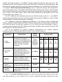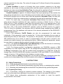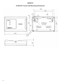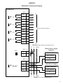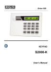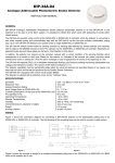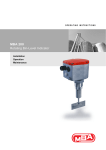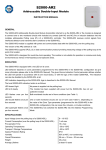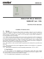
1
ORION ISS
EXECUTIVE RELAY MODULE
S2000-SP1 (ver. 1.56)
INSTRUCTION MANUAL
1 GENERAL TECHNICAL DATA
1.1
General
1.1.1 The S2000-SP1 Executive Relay Module (hereinafter referred to as the module) is
designed to operate as a part of fire alarm systems, intrusion alarm systems, and access
control systems. It operates under control of a fire and alarm console S2000 / S2000M or a
PC with installed Orion Pro software.
1.1.2 Within intrusion alarm systems and access control systems the module is designed to
control various executive devices (lamps, sirens, electromagnetic locks, etc.), to send alarms
to a Central Monitoring Station by means of opening relay contacts, and to cooperate with
other devices and systems on relay level. In fire alarm systems the module is designed to
generate a start pulse for a fire extinguishing control panel.
1.1.3 The module is to be mounted inside the premises and is destined for round-the-clock
operation.
1.1.4 The module must not be used in aggressive medium or dust condition, or in explosionhazardous premises.
1.1.5 The module is intended to be used at operating temperatures −30°С to +55°С.
1.2 Specifications
1.2.1 The module is to be supplied by an external power supply with output voltage
10.2 V dc through 28.4 V dc. It is recommended to use battery backed power supplies of RIP12 or RIP-24 series manufactured by the Bolid Company.
1.2.2 The module power consumption is no more than 2 W.
1
1.2.3 The current consumed by the module (without regard to connected executive
devices):
– 140 mA max at 12 V (all relays are switched on);
– 20 mA max at 12 V (all relays are switched off);
– 70 mA max at 24 V (all relays are switched on);
– 15 mA max at 24 V (all relays are switched off).
1.2.4 The number of executive relays with switching contacts is four.
1.2.4.1 The maximum switching voltage of each relay is 100 V max.
1.2.4.2 The maximum switching current of each relay is 2 А max.
1.2.4.3 The maximum switching power of each relay is 30 W.
1.2.5 The overall dimensions of the module are 156 mm x 107 mm x 39 mm.
1.2.6 The weight of the module doesn’t exceed 0.3 kg.
1.2.7 The pre-operation time of the module since its powering on is 5 s max.
1.3 Standard Delivery
1) S2000-SP1 Executive Relay Module
2) Instruction Manual
3) Installation Manual
4) Woodscrews
5) Wall Plugs
6) DIN 7982 Flat Head Tapping Screw 2.2х6,5
7) Package
– 1 pc.
– 1 pc.
– 1 pc.
– 3 pcs.
– 3 pcs.
– 1 pc.
– 1 pc.
1.4 Performance
1.4.1 Operating algorithms of the module’s relays are defined in the configuration of the
network controller (either S2000 console or PC under ORION Pro software), which controls
the relays by means of commands being sent to the S2000-SP1 relay module over the RS485 interface bus.
1.4.2 The module provides executing the following commands received over the RS-485
interface:
– Reading the configuration parameters stored in the module’s non-volatile memory;
– Writing the configuration parameters stored in the module’s non-volatile memory;
– Assigning a network address to the module;
– Controlling the relays: switching the relay on in accordance with some executive
program;
– Restarting the module;
– Reading module statuses: reading conditions of module’s power inputs and tamper
switch;
– Reading ADC values: reading power voltage (in ADC-values or volts) at the module
power inputs;
– Synchronization of the internal clocks of the module.
1.4.2.1 Control commands can switch relays on and off as well as change-over them
with various frequencies and duty cycles (the ratio between the pulse duration and the
period).
1.4.2.2 Control commands can have unlimited activation time (until the next command
has been received) or limited activation time. In the last case, after having elapsed the
activation time of a command the relay transits to an opposite condition. For example, when
2
the module receives a command “Switch On for a Time”, the relevant relay switches on, while
on elapsing the activation time the relay is switched off. For commands with an activation
time the time can be specified within a command (its value is programmed in the network
controller configuration) and have a value of 0 through 8192 s (2 hours 16 minutes and 32 s)
in the increment of 0.125 s. If the time is missed in the command, its value is defined by the
module’s parameter Activation Time (see Clause 1.4.6) for this relay and can have a value
ranged from 0 to 255 s with the increment of 1 s.
1.4.2.3 A relay control command can include an Activation Delay parameter. In such
case executing the command begins only after the delay has been elapsed, while before
delay’s expiring the previously received command is active. If the Activation Delay parameter
is missed in the command or equal to zero, this command will activate the relay just after
receiving the command. The Activation Delay can have a value of 0 through 8192 s (2 hours
16 minutes and 32 s) in the increment of 0.125 s.
1.4.3 The module transmits the network controller (S2000(M) console or PC under Orion
Pro software) the following messages over the RS-485 interface:
– TAMPER ALARM: The module case has just been open;
– TAMPER RESTORE: The module case has just been closed;
– POWER FAILED: The input power voltage is out of the normal range;
– POWER RESTORE: The input power voltage has come back to the normal range;
– RELAY ON/RELAY OFF: Relay is activated (by any executive program )/ inactivated;
– DEVICE RESTART: Restarting the module by a command or on turning on its power;
– MANUAL TEST: The self-diagnostic mode has just been activated on the module.
1.4.3.1 If at the moment of generation the message there was no communication with
the network controller over the RS-485 interface, the message is stored in the module’s nonvolatile memory, being transmitted upon restoring communication along with the actual time
of its origin. The module can store up to 20 events in its non-volatile memory.
1.4.4 Various modes of module’s operation are shown by the READY indicator as
demonstrated below:
Condition
1. Norm
2. Power failure (the input power voltage is out of the
normal range)
Indicator Behavior
On
Short flashes every 2.5 s
3. No communication over the RS-485 interface
4. Self-diagnostic mode
Flashes once per second
Flashes five times per second
5. Updating software or program memory failure
Flashes twice per second
1.4.4.1 While operating, the module monitors the voltage at its power inputs and,
depending on the given value of Both Power Inputs Monitoring parameter (see
Clause 1.4.6), automatically detects a failure.
Setting Both Power Inputs Monitoring on means that the power voltage should be applied
to both power inputs; and the module enters the Power Failure mode if the power voltage is
out of the normal range at any power input. In this case the module generates one Power
Failure message for this power input (1 or 2) and another Power Failure message for the
3
module itself (input number = 0). READY indicator shall flash with low duty cycle ratio. The
module will return to the quiescent mode when the power is restored on the both inputs, and
after that the module transmits the Power Restored message over the RS-485 interface bus.
If, otherwise, Both Power Inputs Monitoring is set off, the power voltage can be applied to
any of the power inputs. The module enters the Power Failure mode only in case of power
failure at both power inputs and returns to the quiescent mode when the voltage is restored at
any of them. The events Power Failure and Power Restored are generated only for the
module itself (input number = 0).
1.4.4.2 If data are not communicated over the RS-485 interface within 1 s, the READY
indicator begins flashing once per second (provided that the power voltage is in norm). When
communication is restored the indicator is lit steady.
1.4.5 Statuses of relays are displayed by indicators 1 to 4. When a relay is switched off
(that is, normally closed contacts NC and COM are closed while normally open contacts NO
and COM are open), the relevant indicator is off too. When the relay is switched on (that is,
normally closed contacts NC and COM are open while normally open contacts NO and COM
are closed), the relevant indicator is on.
1.4.6 To be adjusted for specific operation requirements, the module supports
programming the following parameters stored in its non-volatile memory:
Description
Value
Range
1. Initial
Condition
The executive program,
executed automatically after
powering on (or resetting) the
module and on receiving a
Return to Initial Condition
command
1 (On),
2 (Off),
9 (Lamp),
10 (Alarm
Output)
2. Activation
Time
The time during which the
relay is active, for the
commands which imply a
limited activation time, if this
time is not received in the
command explicitly
3. On/Off
Events
Enables (disables) transmitting events about relay’s
having activated/inactivated
On/Off
4. Both Power
Inputs
Monitoring
Provides monitoring power
voltage at both power inputs
On/Off
Off
5. Network
Address
The unique number of the
module within the RS-485
interface bus
1…127
127
Parameter
Factory Value
relay 1 relay 2 relay 3 relay 4
2
(Off)
2
(Off)
2
(Off)
2
(Off)
relay 1 relay 2 relay 3 relay 4
0…255 s
60 s
60 s
60 s
60 s
relay 1 relay 2 relay 3 relay 4
Off
Off
Off
Off
1.4.6.1 The Initial Condition parameter of each relay defines the condition of the relay
just after powering on the module until a control command has been received from the
4
network controller for the relay. The values 9 (Lamp) and 10 (Alarm Output) of this parameter
are special ones.
If Initial Condition is equal to 9 (Lamp) then upon module’s powering on the relay
switches on, but in case of losing communication with the network controller over the RS-485
interface for a time exceeding Activation Time, the relay will be switched off and on once per
second. When the communication is restored, the relay will be switched on again.
If Initial Condition is equal to 10 (Alarm Output) then upon powering on the module this
relay will be activated but in case of breaking communication with the network controller over
the RS-485 interface bus for a time more than the parameter Activation Time, the relay will
be switched off. When the communication is restored, the relay will be switched on again.
1.4.6.2 For each relay, its parameter Activation Time defines the time for which the
relay will be activated (switched off) upon module’s receiving a Switch On for a Time or
Switch Off for a Time command in case when the activation time is not explicitly given in the
received command (provided that the module operates under a console S2000 of a version
less than 1.20). If the module S2000-SP1 operates under an S2000 console of a version
1.20+ or Orion Pro software, the activation time is defined during configuring the S2000 or
programming Orion Pro database, with values of the relevant parameters of the S2000-SP1
module being ignored.
1.4.6.3 The parameter On/Off Events can also be programmed for each relay
individually. If the parameter is set up (marked by “+”) then upon activating (by any way) or
inactivating the relay its new status - On (active) or Off (inactive) - will be sent over the RS485 interface bus as an event. In case of communication loss this event is stored in the
module non-volatile memory until restoring the failure. (Before setting this parameter, please
be sure that it is supported by the network controller being in use).
1.4.6.4 The parameter Both Power Input Monitoring controls the function of monitoring
power at both inputs automatically (see Clause 1.4.4.1).
1.4.6.5 To change module’s configuration parameters, an S2000(M) console or IBM
compatible PC is used. When using the PC, the configuration parameters are given by means
of UProg Configuration Tool, with the module being connected to a COM port of the PC
through one of the RS-232/RS-485 interface converters PI-GR and S2000-PI or an S2000(M)
console of version 1.20+ switched to the interface converter mode.
The last version of UProg Configuration Tool as well as additional information about the
module can be downloaded from the Bolid website at the address of www.bolid.com.
2 INSTRUCTIONS
2.1 Safety Precautions
2.1.1 There are no potential hazard circuits within the module.
2.1.2 Do SHUT OFF the device power before mounting, wiring, or maintaining the module.
2.1.3 Mounting and maintaining the module MUST be performed by qualified engineers.
2.2 Preparing for Using
2.2.1 If necessary, change the module’s network address. The address of the module
must not be the same as an address of any device connected to the same RS-485 bus.
2.2.2 Adjust other configuration parameters of the module to meet the specific
requirements to the module.
5
2.2.3 Mount the module on the wall or within a cabinet in accordance with its Installation
Manual (the module is to be mount closely to executive devices at places protected against
atmospheric fallouts, mechanical damage, and unauthorized access). If the module is
mounted in unprotected premises, attach it at a height of at least 2.2 m above the floor.
2.2.4 Wire the module as shown in Annex B.
2.2.4.1 If the module and the network controller are connected to various power supplies,
couple their circuits “0V”.
2.2.4.2 Unless the module is the last device (the furthest from the network controller),
remove the jumper XP2 located near A and B contacts on the module PCB.
2.3 Using the Module
2.3.1 The circuits the module should switch are connected to it in accordance with the
following.
The circuits which unauthorized closing is prohibited even in case of power shut off, must
be connected to normally open relay contacts (“NO” and “COM”).
The circuits, which unauthorized opening is prohibited even in case of power shut off,
must be connected to normally closed relay contacts (“NС” and “COM”).
To close NO relay contacts and to open NC contacts, use the executive program Switch
On (1) or Switch On for a Time (3), with the initial condition for the relay being equal to “Off”.
3 MAINTENANCE
3.1 General
To make sure your S2000-SP1 module keeps proper operability, it must be inspected by
a competent specialist at least on receipt and annually. The inspection algorithm shall
include:
– Visual checking the S2000-SP1 against contaminations and mechanical damage;
– Verifying the S2000-SP1 for secure mounting and wire connection conditions;
– Inspection of the S2000-SP1 operability in accordance with techniques shown below.
3.2 Inspecting Module’s Operability
3.2.1 Preparing:
a) Inspect the package and unpack the module;
b) Inspect the delivery in accordance with Clause 1.3 of this Manual;
c) Make sure the module case is undamaged;
d) Shake the module slightly and make sure there are no foreign particles inside it;
e) Check proper tightening of all terminal blocks.
3.2.2 Inspecting Operability of the Module:
a) Power-up the module in accordance with its connecting diagram (Annex B);
b) Make sure READY indicator begins flashing once per second within 5 s (in case
when RS-485 lines are disconnected from the S2000M console);
c) The current consumed by the module must not exceed 140 mА at 12 V or 70 mА
at 24 V (without regard to consumption of connected executive devices).
3.2.3 Testing the S2000-SP1 in Self-Diagnostic Mode
In self-diagnostic mode the module tests operability of its LEDs and relays.
Before testing the S2000-SP1 in self-diagnostic mode detach its executive circuits
which must not be activated on testing!
6
To activate the self-diagnostic mode, open the module top cover and press the tamper
switch on the PCB in SSSL pattern, where “S” (“short”) stands for holding the tamper switch
pressed for 0.1 s to 0.5 s while “L” (“long”) stands for holding the tamper switch pressed for at
least 1.5 s. Pauses between pressings should be 0.1 to 0.7 s.
If the module operates correctly, its READY indicator shall flash five times per second
while relays “1” to “4” shall be activated for a short time one-by-one.
3.2.4 Inspecting Control Circuits of Power Voltage and Communication over the RS-485
Interface Bus Using the S2000М Console.
Connect the circuits of the RS-485 interface bus to those of the S2000М console. Power
the module and the console on. The module’s READY indicator shall be lit steady. Within a
minute after powering on, the console shall display messages about connecting and resetting
the device with the address assigned to the S2000-SP1. If several messages accumulated by
the module have been received by the console, you can browse them by the arrow buttons
«◄» and «►» on the S2000M.
Then read the value of the module supply voltage by doing the following:
– Select Request Info command in the console menu and then select Zone ADC;
– Enter the network address assigned to the module;
– Enter “1” as the Loop# for the first power supply input.
The value of power supply voltage which will be shown on the console display must be
close to actual voltage on the relevant device input (please check with the tester).
Similarly, check the power supply voltage at the second power supply input.
3.2.5 Make the entry in the inspection log about the results of your inspection.
ZAO NVP Bolid, 4 Pionerskaya Str., Korolev 141070,
Moscow Region, Russia
Phone/fax: +7 495 775-7155
Email: [email protected], [email protected]
www.bolid.com
7
ANNEX A
S2000-SP1 Overall and Mounting Dimensions
8
ANNEX B
S2000-SP1 Connection Diagram
S2000-SP1
XT1.3
"4"
"3"
NO4
18
COM4
17
NC4
16
NO3
15
COM3
14
NC3
13
NO2
12
COM2
11
NC2
10
NO1
9
COM1
8
NC1
7
To executive devices
"2"
"1"
A
XT1.2
XP2
B
6
A
5
RS-485 (from a previous system device)
B GND
Backup Power Supply
(optional)
RIP-12 (RIP-24)
+12V (+24V)
0V
XT1.1
"READY"
+U2
4
0V
3
Main Power Supply
+U1
2
RIP-12 (RIP-24)
0V
1
+12V (+24V)
0V
A
B GND
RS-485 (to a next system device)
9
BOLID ONE YEAR LIMITED WARRANTY
Bolid Company and its divisions and subsidiaries («Seller»), 4 Pionerskaya Str., Korolev 141070,
Moscow Region, Russia warrants its security equipment (the «product») to be free from defects in
materials and workmanship for one year from date of original purchase, under normal use and service.
Seller’s obligation is limited to repairing or replacing, at its option, free of charge for parts or labor, any
product proven to be defective in materials or workmanship under normal use and service. Seller is not
responsible for results where the product is used improperly, where it is used for any application it is not
intended for, used under unacceptable environmental conditions and mishandled or stored under
improperly. Seller shall have no obligation under this warranty or otherwise if the product is altered or
improperly repaired or serviced by anyone other than the Seller. In case of defect, contact the security
professional who installed and maintains your security equipment or the Seller for product repair.
This one year Limited Warranty is in lieu of all other express warranties, obligations or liabilities. There
are no express warranties, which extend beyond the face hereof. Any implied warranties, obligations or
liabilities made by seller in connection with this product, including any implied warranty of merchantability,
or fitness for a particular purpose or otherwise, are limited in duration to a period of one year from the
date of original purchase. Any action for breach of any warranty, including but not limited to any implied
warranty of merchantability, must be brought within 12 months from date of original purchase. In no case
shall seller be liable to anyone for any consequential or incidental damages for breach of this or any other
warranty, express or implied, or upon any other basis of liability whatsoever, even if the loss or damage is
caused by the seller’s own negligence or fault. Some countries do not allow limitation on how long an
implied warranty lasts or the exclusion or limitation of incidental or consequential damages, so the above
limitation or exclusion may not apply to you.
Seller does not represent that the product may not be compromised or circumvented; that the product will
prevent any personal injury or property loss by burglary, robbery, fire or otherwise; or that the product will
in all cases provide adequate warning or protection. Buyer understands that a properly installed and
maintained alarm may only reduce the risk of a burglary, robbery, fire or other events occurring without
providing an alarm, but it is not insurance or guarantee that such will not occur or that there will be no
personal injury or property loss as a result. CONSEQUENTLY, SELLER SHALL HAVE NO LIABILITY
FOR ANY PERSONAL INJURY, PROPERTY DAMAGE OR OTHER LOSS BASED ON A CLAIM THE
PRODUCT FAILED TO GIVE WARNING. HOWEVER, IF SELLER IS HELD LIABLE, WHETHER
DIRECTLY OR INDIRECTLY, FOR ANY LOSS OR DAMAGE ARISING UNDER THIS LIMITED
WARRANTY OR OTHERWISE, REGARDLESS OF CAUSE OR ORIGIN, SELLER’S MAXIMUM
LIABILITY SHALL NOT IN ANY CASE EXCEED THE PURCHASE PRICE OF THE PRODUCT, WHICH
SHALL BE THE COMPLETE AND EXCLUSIVE REMEDY AGAINST SELLER. This warranty gives you
specific legal rights, and you may also have other rights which vary from country to country. No increase
or alteration, written or verbal, to this warranty is authorized.
10