1
Orion ISS
Addressable Polling Loop Controller
S2000-KDL
User’s Manual
This User’s Manual is intended to help for studying operability principles and maintenance of the
S2000-KDL Addressable Polling Loop Controller of version 1.46.
Please read the instructions completely before connecting, operating, adjusting, or maintaining this product.
The following terms are used throughout the Manual:
Addressable Device: The device which supports a special protocol of communicating data with the
S2000-KDL. Each addressable device must be assigned to a unique number of 1 to 127 which
is programmed either by DIP switches on its PCB or stored in the device non-volatile memory.
An addressable device can be a fire or intrusion detector or call point, or input module, or temperature & humidity sensor S2000-VT, or utility meter S2000-ASR2, or expansion module
LEM-Ех rev.2, or executive module S2000-SP2, etc.
Polling Loop: The two-wire multiplex addressable loop of the S2000-KDL through which the controller communicates data with and supplies power to connected addressable devices
Loop Address: A unique number of the addressable device within the polling loop of the S2000-KDL
Addressable Zone: The minimal independently monitored / controlled point in the polling loop of the
S2000-KDL (similar to an alarm loop for a non-addressable installation). An S2000-KDL supports up to 127 addressable zones. Each addressable zone of the S2000-KDL can be configured either as an input or as an output. An input zone is the one through which the controller
monitors the connected initiating devices and analyses received data generating relevant statuses and activating executive modules, if programmed. An output zone is the one to which
the controller sends executive commands for the connected executive module, if programmed
Arming / Disarming: Starting / cancellation generating alarms for an input addressable zone
Network Address: A unique number of the controller (1 to 127) within the local RS-485 network of
the Orion integrated security system
S2000-KDL
Table of Contents
General ................................................................................................................................... 5
Specifications ...................................................................................................................... 11
Operation Principles ............................................................................................................ 15
Multiplex Addressable Polling Loop of the S2000-KDL ............................................................. 16
Input Zones of the Polling Loop ................................................................................................ 18
Zone’s Configuration Parameters
Zone Type 1: Smoke Fire
Zone Type 2: Combined Fire
Zone Type 3: Heat Fire
Zone Type 4: Intrusion
Zone Type 5: Intrusion with Tamper Monitoring
Zone Type 6: Auxiliary
Zone Type 7: Entrance
Zone Type 8: Smoke Analogue With Programmable Thresholds
Zone Type 9: Heat Analogue With Programmable Thresholds
Zone Type 10: Thermostatic
Zone Type 11: Panic
Zone Type 13: Counting
Zone Type 15: Humidity Measurement
Arming / Disarming
Detector’s Operating within the Polling Loop
19
23
23
24
25
26
27
28
29
30
31
32
33
34
35
37
Outputs of the Addressable Polling Loop .................................................................................. 38
Configuration Parameters of Addressable Outputs
Local Executive Programs for Controlling Polling Loop Outputs
39
40
Controlling S2000-KDL Input Zones and User Authorization ..................................................... 48
Configuration Parameters of Readers and User Authenticators
Local Controlling Input Zones of the S2000-KDL
Centralized Control in the Orion System
Compatibility of Readers Used in Orion Systems
48
49
50
50
Light and Sound Indication........................................................................................................ 51
S2000-KDL Light Alarms
Light Indication of Addressable Devices
Light and Sound Indication of the Reader
51
53
54
Communications Between the S2000-KDL and the Network Controller .................................... 56
Transferring Alarms and Status Messages to a Network Controller
Remote Controlling the S2000-KDL over the RS-485 Interface
56
60
Installation ............................................................................................................................ 63
Standard Delivery ..................................................................................................................... 64
Safety Precautions .................................................................................................................... 64
S2000-KDL Mounting................................................................................................................ 64
Connecting the Polling Loop ..................................................................................................... 66
Polling Loop Topology
66
3
www.bolid.com
Orion ISS
The Number of the Addressable Devices to Be Connected
Length of the Polling Loop
68
68
Connecting Addressable Devices ............................................................................................. 69
Wiring the RS-485 Interface Line .............................................................................................. 70
Connecting Power Supplies ..................................................................................................... 70
Connecting A Reader ............................................................................................................... 70
Connecting Readers with Touch Memory Output Interface
Connecting Readers with Wiegand Output Interface
71
72
Connecting an Arming Request Button (Optional) .................................................................... 73
Getting Started ......................................................................................................................... 73
Programming........................................................................................................................ 75
S2000-KDL Address Space Allocation ..................................................................................... 76
Programming Addresses of Devices Connected to the Pooling Loop ....................................... 77
Programming / Changing Device Loop Numbers by Network Controller Tools
77
Programming Address System of the S2000-KDL by Means of UProg ..................................... 79
UProg Interface
Work Settings of the Controller
Network Settings of the S2000-KDL
Setting Operating Parameters of the S2000-KDL
79
81
81
81
Programming Reader Parameters
Working with Addressable Devices Connected to the Polling Loop
Registering Addressable Devices Connected to the Polling Loop
Programming Loop Addresses of Addressable Devices
Requesting Parameters of Addressable Devices
84
85
86
88
89
Programming Input Addressable Zones of the S2000-KDL
Setting the Descriptors of Input Addressable Zones
Linking Inputs of the Polling Loop with its Outputs for Local Control
Copying Settings of Input Addressable Zones
90
91
97
98
Programming Addressable Outputs of the S2000-KDL
Programming Outputs for Remote Control
Programming Outputs for Local Control
99
99
100
Programming Access Groups
Programming Keys
Add / Edit a Key
Delete the Key
Managing the List of Keys
Save Results
103
105
107
108
109
109
Maintenance ....................................................................................................................... 111
Troubleshooting...................................................................................................................... 112
Locally Indicated Troubles
Troubles of the S2000-KDL Transferred to the Orion System
112
113
Preventive Maintenance ......................................................................................................... 115
Self-Diagnostic Routine
www.bolid.com
115
4
S2000-KDL
General
GENERAL
5
www.bolid.com
Orion ISS
S2000-KDL Multiplex Addressable Polling Loop Controller (hereinafter referred to as the S2000-KDL or
the controller) is the basic component of the SPI-2000A Addressable Message Transferring System
which in turns is a part of an Orion integrated security system. The S2000-KDL provides designing
complex and high informative addressable and analogue addressable installations to protect industrial, commercial, and residential premises of any size.
The S2000-KDL provides effective managing fire detection due to the facilities such as delayed
sounder response to allow investigation time, day / night sensibility adjustment of individual devices,
pre-alarm and contamination warning, etc. Through connected addressable executive modules the
S2000-KDL can control executive devices such as light and sound alarms by means of one of the 37
available executive programs.
Built-in control tactics of the S2000-KDL enable using the controller in engineering systems providing
releasing extinguishing agent, keeping temperature and humidity within the preset range, air conditioning and ventilation control, utility submetering, turning equipment on / off, reading digital output
signals from engineering equipment, and so on.
A number of networked controllers – up to 63 х1024 S2000-KDL within a single Orion system – can
be a base for creating flexible and high scalable systems providing centralized security monitoring for
any sized applications scattered over large geographic areas with communicating data through various channels including public switched telephone networks, cellular networks, and LAN.
The S2000-KDL along with S2000-АSR2 consumption metering controllers can be used in specialized
utility submetering installations operated under the Resource software. Also S2000-KDL controllers
can be used to expand inputs of technological controllers S2000-Т in building automation systems
operating under Algorithm software.
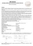
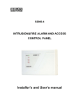
The S2000-KDL provides monitoring and control for up to 127 connected addressable devices (see
Figure 1). The following initiating devices as well as auxiliary devices can be polled by the S2000-KDL
(in any combination):
Analogue addressable photoelectric smoke detectors DIP-34А
Analogue addressable fixed temperature and rate-of-rise detectors S2000-IP
Addressable manual call points IPR 513-3А
Addressable input modules S2000-АR1, S2000-АR2, S2000-АR8 to provide connecting
conventional (zone-type) detectors to the polling loop of the S2000-KDL
Addressable intrusion detectors S2000-IK, S2000-V, S2000-SТ, S2000-STIК, S2000-SHIK,
S2000-PIK, S2000-MW, S2000-SMK, S2000-SМК Estet, etc.
Addressable panic buttons S2000-КТ
Addressable expansion modules LEM-Ех rev.2 to connect intrinsically safe alarm loops to
the polling loop of the S2000-KDL
Addressable combined temperature and humidity sensors S2000-VT
Addressable controllers for two-pulse output meters S2000-АSR2
www.bolid.com
6
S2000-KDL
General
Figure 1. Analogue Addressable Message Transferring Systems Based on S2000-KDL
7
www.bolid.com
Orion ISS
The S2000-KDL polls the connected devices and coordinates their operating, powering them and
communicating data via the polling loop.
The S2000-KDL provides 13 various monitoring tactics which can be programmed individually for
each addressable zone of the polling loop. Among them:
Five various tactics of monitoring fire protection zones
Four tactics for monitoring zones protected against intrusions
Four tactics for monitoring auxiliary (or technological) zones
(including thermostatic, humidity
measurement, and counting) used to integrate various measurement and signaling equipment into
fire & intrusion alarm installations
In a small security system which doesn’t require high informative the S2000-KDL can operate
standalone activating connecting relay modules in response to changing zone conditions accordingly
to programmed cause & effect logic. However, all features of the S2000-KDL can be fully realized only when it operates as a part of on Orion system under a network controller which can be S2000(М)
control console or Orion Pro software. Operating under the network controller, the S2000-KDL transfers alarms and statuses of the polling loop and addressable zones over the RS-485 interface bus in
order to display them remotely by means of the network controller, S2000-К keypads, S2000-BKI
modules or to transmit them further to central monitoring stations via various communication channels
(PSTN, cellular, Ethernet). Moreover, the S2000-KDL can activate centralized control mechanisms
upon receiving relevant commands from the network controller.
The event log of the S2000-KDL can store up to 255 last events.
For authorized control of the system, an external ID reader with the output interface of Touch Memory
or Wiegand can be connected to the special input of the S2000-KDL. The reader can be used both for
local controlling addressable zones of the S2000-KDL (viewing zone statuses and arming / disarming)
and for centralized remote control of various partitions of the Orion system (if the S2000-KDL works
under a network controller). The S2000-KDL provides controlling light and sound indication of the
reader to show system responses to user requests.
The user authenticators or electronic keys (Dallas iButtons, Proximity cards, or digital PIN codes) are
to be preprogrammed, that is enrolled into the S2000-KDL memory with the rights to arm and / or disarm specific addressable zones of the controller (for local arming / disarming) or, alternatively, to the
network controller database (for centralized control).
Three two-color LEDs located on the front panel of the S2000-KDL indicate respectively: controller’s
power conditions, conditions of communicating data through the RS-485 interface bus, and conditions
of the polling loop and communicating data over the polling loop. A special option of the controller
configuration provides the light indication which is need by requirements of European Standard
www.bolid.com
8
S2000-KDL
General
EN54-2. Optionally, the S2000-KDL can also control the indication of connected addressable devices
(if the devices support).
The controller is to be powered by one or two (main and extra) power supplies providing 12 V dc or
24 V dc. It is strongly advised to use Bolid manufactured battery backed power supplies of RIP series.
The S2000-KDL is programmed to meet particular user conditions and specific user needs by means
of the configuration tool for Orion devices, the UProg. The latest version of the UProg Configuration
Tool can be downloaded from the Bolid Company website at the address of www.bolid.com. To be
programmed by means of UProg, the S2000-KDL must be connected to the PC with the installed UProg via one of the Bolid manufactured interface converters such as PI-GR, S2000-PI, S2000-USB, or
USB-RS485.
The S2000-KDL is equipped with a tamper switch which provides tamper alarms when tamper conditions are changed and transferring the alarms to a network controller.
Non-volatile memory of the controller is used to store the network address of the S2000-KDL as well
as its configuration parameters, event buffer, and counted values received from addressable pulse
meter controllers S2000-АSR2 (if connected).
The multiplex addressable polling loop controller is intended for indoor installation and round-theclock operation. The S2000-KDL is not suitable for operation in corrosive and dusty environments as
well as fire-hazardous or explosive areas.
9
www.bolid.com
Orion ISS
www.bolid.com
10
S2000-KDL
Specifications
SPECIFICATIONS
11
www.bolid.com
Orion ISS
Controlled Addressable Devices
Up to 127
Indicators (LEDs)
READY LED to indicate S2000-KDL power condition
RS-485 LED to indicate communications over RS-485
LOOP LED to indicate loop condition
Tamper Switch
Built-in
Event Lop Capacity
255 events
RS-485 Communication Port
Yes
Pre-Operation Time
15 s max
Power Supply
Two power inputs
Bolid manufactured RIP-12 or RIP-24 battery backed power supplies are advisable
Input Voltage
Input Current
At 12 V
10.2 V ÷ 28.4 V dc
400 mА maximum value,
80 mА with no connected devices,
160 mА with 127 connected addressable devices with current consumption of 0.5 mА each
At 24 V
200 mА maximum value,
40 mА with no connected devices,
80 mА with 127 connected addressable devices with current
consumption of 0.5 mА each
Input Power
4 W max
Polling Loop
127 addressable zones
Connectable Devices
– Addressable fire and intrusion detectors
– Addressable call points and panic buttons
– Addressable input modules to connect dry contact detectors
– Addressable loop expansion modules
– Addressable temperature & humidity sensors
– Addressable executive modules
– Addressable consumption meters
Maximum Length
700 m at wire cross section of 0.75 mm2
(with wire diameter at least 0.9 mm)
www.bolid.com
12
S2000-KDL
Specifications
Loop Voltage
10 V
Loop Current
The total current consumption of all connected addressable
devices must NOT exceed 100 mА
External ID Reader
One Reader Input to connect an external reader of Dallas
iButtons, Proximity cards, or PIN codes
Output Interfaces
Touch Memory (1-Wire, µ-LAN), Wiegand
Reader LEDs
Controlling one or two reader LEDs by logical +5 V CMOS
levels, with current values being restricted by 10 mA at direct connection
Sounder
Controlled by logical +5 V CMOS levels
Distance
No more than 100 m from the S2000-KDL
ID Memory Capacity
Up to 512 ID Codes
Operating Temperatures
−30 °С to +50 °С
Relative Humidity
Up to 98% at +25 °С
Ingress Protection Rating
IР20
Overall Dimensions
157 mm х 107 mm х 36 mm
Weight
about 0.3 kg
Average Lifetime
10 years
Programming
By means of the UProg.exe, the tool for configuring
Orion system devices
Connection to a PC
Over RS-485 interface bus via one of the Bolid manufactured interface converters PI-GR, S2000-PI, S2000-USB,
or USB-RS485
13
www.bolid.com
Orion ISS
www.bolid.com
14
S2000-KDL
Operation Principles
OPERATION PRINCIPLES
15
www.bolid.com
Orion ISS
MULTIPLEX ADDRESSABLE POLLING LOOP OF THE S2000-KDL
Two-wire addressable polling loop of the S2000-KDL is designed to communicate data with 127 addressable zones, with each zone being configured (depending on the kind of connected addressable
device) either as:
An Input Zone which can be physically represented by an addressable fire or intrusion detector or call point, monitored circuit of an addressable input module, temperature / humidity
sensor, monitored circuit of a consumption meter S2000-ASR2, and so on, or
An Output, which can be represented by a S2000-SP2 relay output or virtual output of a
LEM-Ех rev.2 and so on.
The addressable polling loop can operate in one of two available modes:
Initialization, or
Quiescent Poll
After starting powering the controller or internal reset, the polling loop of the S2000-KDL enters the
Initialization mode. In such mode the controller starts powering addressable devices and gathering
information about programmed and actually connected addressable devices.
Gathering information, the controller requests types of devices around the entire address range (1 to
127). If the type of a connected addressable device doesn’t match the pre-programmed type of this
one or the type of the programmed zone (the programmed monitoring tactics) doesn’t match the device type, the addressable zone is assigned to the Zone Configuration Error status and the relevant
message is transmitted over the RS-485 interface.
In case of Quiescent Poll, regardless of the zone status, the controller inspects connectivity and statuses of those addressable devices which are currently connected to the S2000-KDL. Also the controller periodically searches connected devices at vacant addresses, searching devices at the addresses for which addressable device’s types are programmed in the console configuration being of
higher priority than at the addresses for which device types are not programmed.
Output circuits of the polling loop are implemented as two output branches, PL1 and PL2. That provides wiring any topology of the polling loop such as a bus, a tree, a ring, or mixed.
The ring topology provides detecting failures of the polling loop. In case of polling loop’s being open
the controller generates 2WIRE 1 LOST and / or 2WIRE 2 LOST message. For zones for which
communications between its related addressable devices and one of the polling loop outputs is lost
the relevant statuses will be assigned. After reconnecting addressable devices with the controller at
the PL1 port and / or the PL2 port 2WIRE 1 RST and / or 2WIRE 2 RST messages will be generated.
To locate short circuit failures, BRIZ short circuit isolators are to be brought to the polling loop. Also
these isolators are used to make branches in the polling loop and to avoid effects of failures in one
www.bolid.com
16
S2000-KDL
Operation Principles
loop segments to another segment. When a short circuit failure has happened, failed part of the loop
between two BRIZ’es (in case of ring topology) of behind the relevant BRIZ is disabled, with the controller generating 2WIRE 1 LOST and / or 2WIRE 1 LOST messages. On recovering normal polling
loop conditions the BRIZ automatically restores connection between isolated segments, and the controller generates 2WIRE 1 RST and / or 2WIRE 2 RST messages.
If communications with an addressable device is lost for both polling loop outputs, the zone is
switched to the Disconnected status. In such case the controller remembers the previous status of the
zone and having found the device with the stored address at one of the polling loop outputs (when the
device is connected again) the status of the zone will be restored. For example, if a zone had Armed
status before losing then after restoring communications the zone will also have Armed status.
17
www.bolid.com
Orion ISS
INPUT ZONES OF THE POLLING LOOP
The input zones of the S2000-KDL are the points of connecting initiating addressable devices to the
polling loop. Up to 127 various respondent addressable devices can be connected to the S2000-KDL
among them (in any combination):
Analogue addressable photoelectric smoke detectors DIP-34А
Analogue addressable fixed temperature and rate-of-rise detectors S2000-IP
Addressable manual call points IPR 513-3А
Addressable input modules S2000-АR1, S2000-АR2, S2000-АR8 to provide connecting conventional (zone-type) detectors into the polling loop of the S2000-KDL
Addressable intrusion detectors S2000-IK, S2000-V, S2000-SТ, S2000-STIК, S2000-SHIK,
S2000-PIK, S2000-MW, S2000-SMK, S2000-SМК Estet, etc.
Addressable panic buttons S2000-КТ
Addressable loop extension modules LEM-Ех rev.2 to provide connecting intrinsically safe
dry contact detectors
Addressable combined temperature and humidity sensors S2000-VT
Addressable controllers S2000-АSR2 for two pulse output consumption meters
Some addressable devices can occupy several addresses within the address space of the polling
loop (see manuals for the devices being in use).
Having polled the connected addressable devices, the controller assigns all the addressable zones to
some logic statuses, depending on:
−
The status returned by the addressable device and the parameter value measured by the
device (such as optical density, temperature, etc.) or the resistance measured in the monitored circuit of the input module (for non-addressable detectors), and
−
The monitoring tactics given for the addressable zone or its Zone Type (all monitoring tactics
supported be the S2000-KDL as well as appropriate zone statuses will be considered below
in this Section), and
−
The current monitoring status of the zone (whether the zone is armed or disarmed)
Having assigned statuses to zones, the S2000-KDL:
−
Automatically transfers changed zone statuses over the RS-485 interface, and
−
If preprogrammed in its local configuration, controls its executive outputs, and
−
Returns current zone statuses (if requested locally) by light indicator and sounder of the
reader connected to the S2000-KDL
www.bolid.com
18
S2000-KDL
Operation Principles
Zone’s Configuration Parameters
Table 1 shows the list of configuration parameters that can be programmed for the S2000-KDL to define various tactics of operating input zones of the polling loop.
Table 1. Parameters of Input Addressable Zones of the S2000-KDL
Parameter
Description
Range
Factory
value
Zone Type
Defines monitoring tactics for a zone
and a range of connectable addressable devices
(intrusion or fire equipment; temperature or smoke detector, etc.)
1 ÷ 11, 13, 15
(see below)
5
Auto Rearming
Automatic switching from Arming
Failed status to Armed status after
zone’s being restored
On / Off
Off
Auto Arming
After Alarm
Automatic switching from Intrusion
Alarm, Fire Alarm, or Fire Prealarm
status to the Armed status
upon restoring the zone
On / Off
Off
Disarmed
Zone
Monitoring
Enables to transfer status changes for
disarmed intrusion zones
of types 4, 5, 7, 11
On / Off
Off
Never Disarmed
The zone is armed permanently and
cannot be disarmed
On / Off
Off
Arm / Disarm
by Group
Upon controller’s receiving a Group
Arming / Disarming command from the
network controller, all zones with this
parameter being set are
armed / disarmed all at once (the parameter is valid only for those zones
which are assigned to specific device
types in the controller database)
On / Off
Off
Arming Delay
The delay between receiving an arming
command and switching the zone to
the Armed status
0…255 s
0
Recovery Time
The time during which a zone of the
Type #6 should be in norm to consider
this zone to be recovered. Also this is
the time for operating given tactics
Auto Arming After Alarm,
Disarmed Zone Monitoring
0…255 s
0
19
www.bolid.com
Orion ISS
Parameter
Description
Range
Factory
value
Alarm Delay
When this time is elapsed the zone of
the Type #7 will be switched
from Entrance Alarm status
to the Intrusion Alarm status
0…255 s
0
Fire Day
Sensitivity
Threshold
The level of smoke (in terms of standard units) to respond with a Fire Alarm
message for Day mode
90…120
100
Prealarm Day
Sensitivity
Threshold
The level of smoke (in terms of standard units) to respond with a
Fire Prealarm message for Day mode
70…90
80
Fire Night
Sensitivity Threshold
The level of smoke (in terms of standard units) to respond with a Fire Alarm
message for Night mode "
80…100
90
Prealarm Night
Sensitivity
Threshold
The level of smoke (in terms of standard units) to respond with a
Fire Prealarm message for Night mode
70…80
70
Contamination
Threshold
(for Type #8)
The level of dust in the smoke chamber
of the detector (in terms of standard
units) to respond with a
Service Required message
10…60
50
Fire Temperature
The value of temperature in oC to respond with Fire Alarm message
+54 oC …+85 oC
54
Prealarm
Temperature
The value of temperature in oC to respond with Fire Prealarm message
0 oC …+81 oC
50
Temperature
Decreased
Threshold
The value of temperature in oC to respond with Temperature Low message
– 55 oC …+125 oC
20
Temperature
Increased
Threshold
The value of temperature in oC to respond with Temperature High message
– 55 oC …+125 oC
22
Humidity
Decreased
Threshold
The value of relative humidity in % to
respond with Level Low message
0…100 %
60
Humidity
Increased
Threshold
The value of relative humidity in % to
respond with Level High message
0…100 %
70
Device Indication
Control
0 – Indication Disabled (the S2000KDL disables device indication);
1 – Standalone indication control;
2 – Controlling device indication by the
S2000-KDL
0…2
1
www.bolid.com
20
S2000-KDL
Operation Principles
Parameter
Description
Range
Factory
value
Save Mode
Switches the addressable device to the
energy save mode depending on the
zone status
(for example, in the Disarmed status)
On / Off
Off
Counting
Threshold
For the zone of the Type#13 this is the
number of pulses which are to accumulated by the S2000-ASR2 until this
number will be sent to the S2000-KDL
0…65535
1000
Counter Integral
Action Time
For the zone of the Type#13 this is the
integral action time for filtering in monitored circuits noises with frequency
more than frequency of counted pulses
0.5 ms…127.5 ms
1
Night-to-Day
Threshold
(for Type 8)
The time when the Night operating
mode of the detector is turned off while
the Day mode is turned on (HH:MM)
00:00…23:59
09:00
Day-to-Night
Threshold
(for Type 8)
The time when the Day operating mode
of the detector is turned off while the
Night mode is turned on (HH:MM)
00:00…23:59
21:00
The main configuration parameter of each zone which defines tactics of its monitoring and available
kinds of monitored devices is Zone Type.
The S2000-KDL supports the following types of zones of different functionality:
Fire
1 – Smoke Fire
2 – Combined Fire
3 – Heat Fire
8 – Smoke Analogue With Programmable Thresholds
9 – Heat Analogue With Programmable Thresholds
Intrusion
4 – Intrusion
5 – Intrusion With Tamper Check
7 – Entrance
11 – Panic
Auxiliary
6 – Auxiliary
10 – Thermostatic
13 – Counting
15 – Humidity Measurement
All types of zones along with their specific parameters will be considered in following Sections. Here
we will describe parameters common for a number of input addressable zones of the polling loop.
21
www.bolid.com
Orion ISS
The parameter Auto Rearming is to be set if the zone being in the Disarmed status (see Section
Arming / Disarming below) is supposed to be armed automatically when it is recovered after breaking.
The parameter Auto Arming After Alarms provides automatic switching from the statuses Intrusion
Alarm, Fire Alarm, and Fire Prealarm to the Armed status upon recovering the zone after its breaking.
In such a case, to be armed the zone must be in norm during the time more or equal to Recovery
Time.
If the parameter Disarmed Loop Monitoring is set on for a zone of the Type #4, #5, #7, or 11 then
the status changes of the zone will be monitored even though it is disarmed. When the zone has been
broken / recovered the controller generates messages Not Ready To Arm and Ready To Arm respectively. The zone to be considered as recovered it must be in norm for a time equal to Recovery Time.
If a zone must be monitored (be armed) round the clock use the parameter Never Disarmed. This
parameter is set on for fire protection and panic zones #1, #3, and #11 to avoid their accidental disarming. When a Disarm command has been received for a zone which Never Disarmed parameter is
set on, the zone either enters the armed status if it was in norm previously or, otherwise, the controller
generates a message about the current status of the zone.
The parameter Arm / Disarm by Group provides simultaneous arming or disarming all the zones, for
which this parameter is set on, using the command Group Arming (Disarming). The option is only valid for zones which are assigned to specific device types in the controller database.
The Alarm Delay parameter defines a time (in seconds) in which the controllers tries to arm the zone
after generating relevant command. Non-zero alarm delay is used for intrusion zones, for example, for
an entrance door, in order a user to have some time to leave premises after arming the security system.
The Save Mode parameter allows regulating power consumption of the addressable device depending on the status of the device’s zone. For detectors with microwave modules this parameter provides
switching off the active element to reduce the impact of microwave radiation on people in the protected premises. An addressable device is switched to the Save Mode on zone’s entering the Disarmed
status, the parameter Disarmed Loop Monitoring being ignored.
Switching to the Save Mode is only provided for those addressable devices which support this mode and the communication protocol DPLS_v2.xx (see manuals of addressable devices)
The Device Indication Control parameter defines the indication mode of the addressable device
connected to the current input zone of the S2000-KDL. The values of this parameter and the relevant
indication modes can be as follows:
www.bolid.com
22
S2000-KDL
Operation Principles
0
Indication Disabled (the S2000-KDL disables device indication)
1
The LED of the addressable device indicates statuses of the addressable device and
the parameter monitored by the device according to own pre-programmed tactics of the
device, as described in the device specification
2
LED indication is controlled by a S2000-KDLlogic and shows zone statuses (see Section Light Indication of Addressable Devices of this Manual)
Controlling the LED is only provided for those addressable devices which support the
communication protocol DPLS_v2.xx (see manuals of addressable devices).
To provide controlling LEDs of conventional detector from third party manufacturers interface them in the polling loop through the input modules S2000-АR1 rev.04
Zone Type 1: Smoke Fire
A zone of Type 1 is designed to monitor photoelectric smoke detectors DIP-34А operated in threshold-addressable mode returning the controller fire alarm statuses when the smoke level measured by
the detector exceeds the internal threshold of the detector.
Available statuses of a zone of the Type #1 are the following:
ARMED
The zone is fully monitored
DISARMED
The zone is in norm if there is no faults
ARMING DELAY
Arming the zone is delayed until the Arming Delay time has
elapsed
ARMING FAILED
The parameter monitored by the addressable device is out of
normal range at the time of arming the zone
FIRE ALARM
The DIP-34А has detected smoke level’s exceeding its own
sensitivity threshold
OPEN FAILURE
(see Table 2)
TROUBLE
The DIP-34A fails to measure smoke level
SERVICE REQUIRED
A contamination self-compensation threshold for the smoke
chamber of the DIP-34A has been exceeded
Zone Type 2: Combined Fire
Zones of the Type#2 are expected to monitor statuses of the addressable input modules S2000-АR2,
S2000-АR8, and loop expansion modules LEM-Ех rev.2 providing sensing such statuses of monitored
circuits as Norm, Fire Alarm, Open Failure, and Short Failure.
Available statuses of a zone of the Type #2 are the following:
23
www.bolid.com
Orion ISS
ARMED
The zone is fully monitored
DISARMED
The zone is in norm if there is no faults
ARMING DELAY
Arming the zone is delayed until the Arming Delay time has
elapsed
ARMING FAILED
The parameter monitored by the addressable device is out of
normal range at the time of arming the zone
FIRE ALARM
(see Table 2)
OPEN FAILURE
(see Table 2)
SHORT FAILURE
(see Table 2)
Table 2. How the S2000-KDL Interprets Statuses of the Input Modules’ Monitored Circuits
Zone
Type
Available Statuses of Monitored Circuits
Norm
Alarm
Open Failure
Short Failure
Tamper Alarm
1
Armed
Open Failure
Open Failure
Fire Alarm
–
2
Armed
Fire Alarm
Open Failure
Short Failure
–
3
Armed
Short Failure
Fire Alarm
Short Failure
–
4
Armed
Intrusion Alarm
Intrusion Alarm
Intrusion Alarm
–
5
Armed
Intrusion Alarm
Intrusion Alarm
Intrusion Alarm
Intrusion Alarm
6
Norm
Trouble
Trouble
Trouble
–
7
Armed
Entrance Alarm
Entrance Alarm
Entrance Alarm
Intrusion Alarm
11
Armed
Panic Alarm
Panic Alarm
Panic Alarm
Panic Alarm
NOTES:
The status Alarm is available only for S2000-АR2 and S2000-АR8 modules.
All statuses of monitored circuits shown in the table concern zones being in the
Armed status expect for zones of the Type #6.
Zone Type 3: Heat Fire
The following devices can be assigned to a zone of the Type #3:
a)
analogue addressable fixed temperature and rate-of-rise detectors S2000-IP, S2000-IP rev.01,
and S2000-IP rev.02 operated in addressable threshold mode, or
b)
S2000-АR1 addressable single-input modules to connect dry contact fire heat detectors into the
polling loop, or
c)
IPR 513-3А addressable manual call points
www.bolid.com
24
S2000-KDL
Operation Principles
Available statuses of a zone of the Type #3 are the following:
ARMED
The zone is fully monitored
DISARMED
The zone is in norm if there is no faults
ARMING DELAY
Arming the zone is delayed until the Arming Delay time has elapsed
ARMING FAILED
The parameter monitored by the addressable device is out of normal
range at the time of arming the zone
FIRE ALARM
−
The heat detector has registered temperature’s change or exceeding the predetermined value corresponding to a condition of entering Fire Alarm status (fixed temperature and rate-of-rise mode), or
−
The manual call point has been activated (its glass has been broken), or
−
As shown in Table 2 for the S2000-АR1
SHORT FAILURE
(see Table 2)
TROUBLE
The S2000-IP fails to measure temperature
Zone Type 4: Intrusion
A zone of the Type #4 is to be used to monitor any intrusion detectors which are not supposed to
send signals about tampering the detector (or which doesn’t support transmitting tamper alarms).
These zones are recommended to assign to:
a)
S2000-SMK addressable magnetic contacts, or
b)
S2000-SMK Estet addressable magnetic contacts for metal doors, or
c)
S2000-АR2 addressable double-input modules, or
d)
LEM-Ех rev.2 loop expansion modules to connect conventional intrinsic safe intrusion detectors
Available statuses of a zone of the Type #4 are the following:
ARMED
The zone is fully monitored
DISARMED
The zone is in a norm (the Disarmed Loop Monitoring parameter
being set on); there is no faults
NOT READY TO ARM
The zone has been broken being disarmed (the Disarmed Loop
Monitoring parameter being set on)
TROUBLE
The addressable device has failed
ARMING DELAY
Arming the zone is delayed until the Arming Delay time has elapsed
25
www.bolid.com
Orion ISS
ARMING FAILED
The parameter monitored by the addressable device is out of normal
range at the time of arming the zone
INTRUSION ALARM
−
The addressable detector has responded with an alarm (for example, breaking a glass has detected or infrared field has been violated), or
−
The contacts of the S2000-SМК has been open, or
−
The addressable device has failed provided that the zone was
armed, or
−
The addressable input module has been in one of the statuses
shown in Table 2
Zone Type 5: Intrusion with Tamper Monitoring
A Zone of the Type #5 defines the tactics of monitoring addressable devices which provides not only
generating intrusion alarms but also responding with special signals when their enclosure is open.
The following addressable devices can be connected to zones of the Type 5:
a)
S2000-SТ addressable glass break detectors, or
b)
S2000-IK addressable passive infrared motion detectors, or
c)
S2000-PIK addressable ceiling-mount motion detectors, or
d)
S2000-MW addressable microwave intrusion detectors, or
e)
S2000-STIK addressable combined motion and glass break detector, or
f)
S2000-PIK-ST addressable combined ceiling-mount motion and glass break detectors, or
g)
S2000-SHIK addressable curtain PIR motion detectors, or
h)
S2000-V addressable shock detectors, or
i)
S2000-SMK addressable magnetic contacts, or
j)
S2000-SMK Estet addressable magnetic contacts for metal doors, or
k)
S2000-КТ addressable panic buttons, or
l)
S2000-АR1, S2000-АR2, and S2000-АR8 addressable input modules, or
m)
LEM-Ех rev.2 intrinsically safe loop extension modules
Available statuses of a zone of the Type #5 are the following:
ARMED
The zone is fully monitored
DISARMED
The zone is in a norm (the Disarmed Loop Monitoring parameter
being set on); the addressable device enclosure is closed, the TAM-
www.bolid.com
26
S2000-KDL
Operation Principles
PER contacts of the S2000-АR1 is closed, there is no faults
TAMPER ALARM
The zone being in one of the statuses Disarmed, Arming Failed, or
Arming Delay, the enclosure of the addressable device or addressable input module is open, or the TAMPER contacts of the S2000-АR1
is open
NOT READY TO ARM
The zone has been broken being disarmed (the Disarmed Loop
Monitoring parameter being set on)
TROUBLE
The addressable device has failed
ARMING DELAY
Arming the zone is delayed until the Arming Delay time has elapsed
ARMING FAILED
The parameter monitored by the addressable device is out of normal
range at the time of arming the zone
INTRUSION ALARM
−
The addressable detector has responded with an alarm (for example, breaking a glass has detected or infrared field has been violated), or
−
The contacts of the S2000-SМК has been open, or
−
The detector enclosure has been open, or
−
The addressable device has failed provided that the zone was
armed, or
−
The status or the input module’s monitored zone is not Norm
Zone Type 6: Auxiliary
Auxiliary zones are intended to monitor statuses of doors in gaseous and dry chemical fire suppressing systems, to monitor conditions of fire protection equipment, to block executing of tactics concerning to fixed firefighting systems as well as to monitor conditions of equipment and alarms not directly
connected with the security and fire alarm systems.
All addressable devices designed to work within the polling loop can be included into zones of the
Type #6, except S2000-ASR2 utility meters and S2000-VТ combined temperature and humidity sensors.
Available statuses of a zone of Type #6 are the following:
AUXILIARY ZONE RESTORED
The zone is fully monitored
AUXILIARY ZONE ALARM
Status of the detector or monitored circuit (as shown
in Table 2) differs from Norm
27
www.bolid.com
Orion ISS
The zone is switched from the Auxiliary Zone Restored status to the Auxiliary Zone Alarm status when
the relevant detector or monitoring circuit of the input module responds with an alarm i(for monitored
circuits see Table 2). The zone is switched from the Auxiliary Zone Alarm status to the Auxiliary Zone
Restored status if it has been in norm for the time equal to Recovery Time – see Section Zone’s
Configuration Parameters of this Manual.
Zone Type 7: Entrance
The Zone Type #7 (Entrance Zone) is similar to the Zone Type #5 except that breaking an armed
zone of the Type #7 switches the zone firstly to the Entrance Alarm status. If after elapsing some predetermined time no measures are taken to disarm the zone or to arm it then the zone is switched to
the Intrusion Alarm status.
While the zone is being in the Entrance Alarm status no relay assigned to this zone with one of the
general executive programs (programs #1 to #8) or the Siren program (program #12) is activated.
This allows a user entering the premises to reach the place where the alarm system control is located
and to disarm the system without issuing alarms.
The time during which breaking an entrance zone is not considered to be an intrusion and no intrusion
alarm is generated is defined by the Alarm Delay parameter in the controller configuration individually
for each zone. If this parameter I set to zero for a zone then upon breaking the zone the Entrance
Alarm status will be bypassed and the zone will be switched to the Intrusion Alarm status immediately.
The following addressable devices can be assigned to zones of the Type #7:
a)
S2000-IK addressable passive infrared motion detectors, or
b)
S2000-SHIK addressable curtain PIR motion detectors, or
c)
S2000-SМК and S2000-SМК Estet addressable magnetic contacts, or
d)
S2000-АR1, S2000-АR2, and S2000-АR8 addressable input modules, or
e)
LEM-Ех rev.2 intrinsically safe loop extension modules
Available statuses of a zone of the Type #7 are the following:
ARMED
The zone is fully monitored
DISARMED
The zone is in a norm (the Disarmed Loop Monitoring parameter
being set on); the addressable device enclosure is closed, the TAMPER contacts of the S2000-АR1 is closed, there is no faults
TAMPER ALARM
The enclosure of the addressable detector or input module being in
statuses Disarmed, or Arming Failed, or Arming Delay is open
NOT READY TO ARM
The zone has been broken, the Disarmed Loop Monitoring parameter being set on
www.bolid.com
28
S2000-KDL
Operation Principles
TROUBLE
The addressable device has failed
ARMING DELAY
Arming the zone is delayed until the Arming Delay time has elapsed
ARMING FAILED
The parameter monitored by the addressable device is out of normal
range at the time of arming the zone
ENTRANCE ALARM
−
The addressable detector has responded, or
−
The contacts of the S2000-SМК has been open, or
−
The monitored circuit of the addressable input module has entered
one of the statuses described by Table 2 for zones of the Type #7
INTRUSION ALARM
−
The Alarm Delay time has elapsed after zone’s having entered the
Entrance Alarm status
−
An addressable device trouble has occurred, with the zone being
armed
Zone Type 8: Smoke Analogue With Programmable Thresholds
A zone of the Type #8 is intended to monitor analogue addressable smoke photoelectric detectors
DIP-34A, DIP-34A rev.01, and DIP-34A rev.02 operated in analogue mode.
The polling loop being in the quiescent mode, the controller requests the digital values of smoke concentration measured by the detector. For each zone of the Type #8 the Prealarm Sensitivity
Threshold and Fire Sensitivity Threshold are to be programmed to issue fire prealarms and fire
alarms respectively. These thresholds are programmed for Day Mode and Night Mode separately.
Periodically the S2000-KDL requests the values of contamination within smoke chamber of the detector and compares these values with the Contamination Thresholds programmed for each zone of
the Type #8 individually.
Available statuses of a zone of the Type #8 are the following:
ARMED
The zone is entirely monitored; no preprogrammed thresholds (Fire Sensitivity Threshold, Prealarm Sensitivity Threshold, or Contamination
Threshold) are exceeded
DISARMED
The zone is monitored only for troubles and exceeding the Contamination Threshold
ARMING DELAY
Arming the zone is being delayed
ARMING FAILED
While the zone is being armed, one or more of its programmed thresholds
for the current time mode (Fire Sensitivity Threshold, Prealarm Sensitivity Threshold, or Contamination Threshold) is exceeded or a trouble
has occurred
29
www.bolid.com
Orion ISS
FIRE PREALARM
The smoke concentration measured by the detector has exceeded the
Prealarm Sensitivity Threshold preprogrammed for the zone for the current time-of-the-day mode (Night / Day)
FIRE ALARM
The smoke concentration measured by the detector has exceeded the
Fire Sensitivity Threshold preprogrammed for the zone for the current
time-of-the-day mode (Night / Day)
TROUBLE
The DIP-34A fails to measure smoke level
SERVICE REQUIRED
The Contamination Threshold or the contamination self-compensation
threshold for the smoke chamber of the DIP-34A has been exceeded
Zone Type 9: Heat Analogue With Programmable Thresholds
A zone of the Type #9 is intended to monitor analogue addressable fixed temperature and rate-of-rise
detectors S2000-IP, S2000-IP rev.01, and S2000-IP rev.02 operated in analogue mode.
The polling loop being in the quiescent mode, the controller requests the digital values of temperature
measured by the detector. For each zone of the Type #9 the Prealarm Sensitivity Threshold and
Fire Sensitivity Threshold are to be programmed to issue fire prealarms and fire alarms respectively.
Available statuses of a zone of the Type #9 are the following:
ARMED
The zone is monitored; neither Fire nor Prealarm thresholds are exceeded
DISARMED
The zones is monitored only for troubles
ARMING DELAY
Arming the zone is delayed until the Arming Delay time has elapsed
ARMING FAILED
While the zone is being armed, one or more of its programmed thresholds
(Fire Sensitivity Threshold or Prealarm Sensitivity Threshold) is exceeded or a trouble has occurred
FIRE PREALARM
The temperature measured by the detector has exceeded the Prealarm
Sensitivity Threshold preprogrammed for the zone
FIRE ALARM
The temperature measured by the detector has exceeded the Fire Sensitivity Threshold preprogrammed for the zone
TROUBLE
www.bolid.com
The detector fails to measure temperature
30
S2000-KDL
Operation Principles
Zone Type 10: Thermostatic
This type of zones provides using fire heat detectors as temperature meters and to create thermal
control systems.
The polling loop being in the quiescent mode, the controller requests the digital values of temperature
measured by the detector at its location point. Arm and Disarm commands provide involving and excluding the zone from the thermostatic system respectively.
The following devices can be assigned to a zone of the Type #10:
a)
analogue addressable fixed temperature and rate-of-rise detectors S2000-IP, S2000-IP rev.01,
and S2000-IP rev.02 used to measure temperature at the location point of the detector
b)
S2000-VТ combined temperature and humidity sensors (temperature measurement channel)
Available statuses of a zone of the Type #10 are the following:
DISARMED
The zone is monitored only for troubles; the S2000-KDL neither
analyses temperature values received from the device nor outputs messages about temperature increasing / decreasing; zone
statuses don’t affect thermal control process
ARMING DELAY
Delaying to use the zone in thermal control system operating
TEMPERATURE LOW
The measured temperature has dropped below the value of
Temperature Decreased Threshold predetermined for the
zone
TEMPERATURE HIGH
The measured temperature has exceeded the value of Temperature Increased Threshold predetermined for the zone
TEMPERATURE NORM
The measured temperature is between values of Temperature
Decreased Threshold and Temperature Increased Threshold predetermined for the zone
TROUBLE
The device fails to measure temperature
The following configuration parameters are to be programmed for a zone of the Type #10 (see also
Table 1):
Temperature Increased Threshold: the value of temperature in degrees Centigrade at the location
point of the device for the zone to be considered in the Temperature High status
Temperature Decreased Threshold: the value of temperature in degrees Centigrade at the location
point of the device for the zone to be considered in the Temperature Low status
31
www.bolid.com
Orion ISS
Arming Delay for a Thermostatic zone defines the time in seconds, that should pass between controller’s receiving an Arm command and starting requesting temperature measurements for
the zone
DO NOT confuse the temperature increased / decreased thresholds defined for the
Thermostatic zone and the same thresholds defined for addressable outputs of the
S2000-KDL.
Temperature value’s being out of the range programmed for a Thermostatic zone causes
the S2000-KDL to switch the zone to the Temperature High / Temperature Low status
and to transmit the relevant message to the network controller.
If, on the contrary, measured temperature values are out of the range programmed for an
output assigned with this zone in the S2000-KDL configuration, the controller activates
the output as defined by its predetermined executive program. The controller also transmits the changed output status to the network controller if the relevant switch in the output’s settings allows that – see Section Configuration Parameters of Addressable Outputs.
Zone Type 11: Panic
A zone of the Type #11 (Panic zone) realizes a tactics of hidden alarms when the controller having
received a detector alarm response generate a special message Silent Alarm but neither light nor
sound alarms are tuned on.
The following devices can be monitored as zones of the Type #11:
a)
S2000-КТ Addressable Panic Button, or
b)
Addressable input modules interfaced various panic buttons and pedals, or
c)
S2000-SМК and S2000-SМК Estet Addressable Magnetic Contacts
d)
LEM-Ex rev.02 Loop Expansion Module interfaced intrinsically safe alarm loops
Available statuses of a zone of the Type #11 are the following:
ARMED
The zone is fully monitored
DISARMED
The zone is in a norm (the Disarmed Loop Monitoring parameter
being set on); the addressable device enclosure is closed, the TAMPER contacts of the S2000-АR1 is closed, there is no faults
TAMPER ALARM
The enclosure of the addressable detector or input module being in
statuses Disarmed, or Arming Failed, or Arming Delay is open
NOT READY TO ARM
The zone has been broken, the Disarmed Loop Monitoring parameter being set on
www.bolid.com
32
S2000-KDL
Operation Principles
TROUBLE
The addressable device has failed
ARMING DELAY
Arming the zone is delayed until the Arming Delay time has elapsed
ARMING FAILED
The parameter monitored by the addressable device is out of normal
range at the time of arming the zone
PANIC ALARM
Breaking of the monitored circuit of the input module has been detected (see Table 2); the device has failed provided that the zone is
being armed
Zone Type 13: Counting
A zone of the Type #13 is designed to connect addressable controllers S2000-АSR2 with one or two
included pulse output meters ( of water, gas, etc.)
Available statuses of a zone of Type 13 are the following:
CONNECTED
The S2000-АSR2 is connected; pulses are being counted
SHORT CIRCUIT
A short circuit failure in a monitored circuit of the S2000-ASR2;
no pulses are counted
OPEN CIRCUIT
A monitored circuit of the S2000-ASR2 is open;
no pulses are counted
This type of zone is to be used when the addressable pulse-meter controllers connected to the
S2000-KDL operate in a utility submetering system controlled by Recourse or Orion Pro software.
An S2000-АSR2 is designed to control utility meters with pulse outputs for which a single pulse corresponds to a certain amount of measured physical material. The counted number of pulses is stored in
the RAM of the S2000-АSR2, so on shutting off the power of the S2000-АSR2 the accumulated number is lost. So, for a zone of the Type #13 the parameter Counting Threshold is to be specified,
which is a number of pulses that are accumulated in the S2000-ASR2 memory before sending this
number to the S2000-KDL. The controller summarizes the received values and stores them into own
non-volatile memory. The maximum number of pulses that can be stored in the memory of the S2000KDL is 2·1014.
The value of Counting Threshold should be selected so that, on the one hand, this value can be ignored in case of shutting down power or any other failure of the S2000-АSR2, but on the other hand,
sending pulses would not overload the polling loop of the S2000-KDL.
The Counter Integral Action Time parameter allows avoiding false-count pulses for different types of
meters. The value of Counter Integral Action Time is set so that it was maximum two times less
than duration of a countable pulse.
33
www.bolid.com
Orion ISS
Zone Type 15: Humidity Measurement
Zone Type #15 is used for monitoring the hydrometrical channel of an S2000-VТ addressable combined temperature & humidity sensor. For this type of zone the S2000-KDL provides measuring humidity values while operating humidity control installations.
The S2000-KDL requests digital values of measured humidity through its polling loop when it is in the
quiescent mode. The Humidity Increased Threshold and Humidity Decreased Threshold should be
given for each zone of the Type #15.
Arm and Disarm commands cause respectively involving the zone into and its eliminating from operating of a humidity measurement and control system.
Available statuses of a zone of the Type #15 are the following:
DISARMED
Only troubles are monitored. Neither humidity is measured nor
the zone affects humidity control
ARMING DELAY
Activating the zone is delayed until the Arming Delay time has
elapsed
LEVEL LOW
The measured value of the humidity has dropped below the
predetermined Humidity Decreased Threshold value
LEVEL HIGH
The measured value of the humidity has exceeded the predetermined Humidity Increased Threshold value
LEVEL NORM
The measured value of the humidity is within the range between
the Humidity Decreased Threshold value and the Humidity Increased Threshold value
TROUBLE
The addressable device failed to measure temperature
The following configuration parameters are to be set for a zone of the Type #15 (see Table 1):
Humidity Increased Threshold: the value of relative humidity in % at the place of S2000-VТ location
which causes the Zone to enter Level High status
Humidity Decreased Threshold: the value of relative humidity in % at the place of S2000-VТ location
which causes the Zone to enter Level Low status
Arming Delay for a Humidity Measurement zone defines the time in seconds, after elapsing which
since receiving an Arm command the controller will request measured humidity values for
this zone
www.bolid.com
34
S2000-KDL
Operation Principles
DO NOT confuse the humidity increased / decreased thresholds defined for the Humidity
Measurement zone and the same thresholds defined for addressable outputs of the
S2000-KDL.
Humidity value’s being out of the range programmed for a Humidity Measurement zone
causes the S2000-KDL to switch the zone to the Level High / Level Low status and to
transmit the relevant message to the network controller.
If, on the contrary, measured humidity values are out of the range programmed for an
output assigned with this zone in the S2000-KDL configuration, the controller activates
the output as defined by its predetermined executive program. The controller also transmits the changed output status to the network controller if the relevant switch in the output’s settings allows that – see Section Configuration Parameters of Addressable Outputs.
Arming / Disarming
The S2000-KDL supports arming and disarming for all input addressable zones except zones #13
(Counting).
In case of local control Arm / Disarm commands are generated by the controller after user’s presenting the proper authenticator (electronic key) on the reader connected to the S2000-KDL (see Section
Local Controlling Input Zones of the S2000-KDL of this Manual). Otherwise, in case of centralized
control Arm / Disarm commands are received from the network controller over the RS-485 interface.
The S2000-KDL provides executing group commands for arming / disarming received from the network controller for those zones which have the Group Arming / Disarming switch set in the S2000KDL configuration.
For fire and intrusion protection zones (of Types #1 – #5, #7 – #9, and #11) receiving an Arm
command causes the controller to arm the zone. If before receiving the command the zone was in
norm, it is armed, with the S2000-KDL sending the network controller via the RS-485 interface the
message about arming the zone. In any other case the S2000-KDL considers the zone status to be
Arming Failed and transmits this status to the network controller.
A zone of the Type #8 is considered by the S2000-KDL to be in the Arming Failed status if the value
measured by the smoke detector has exceeded the Prealarm or Fire sensitivity threshold predetermined for the zone for the current time of the day (Day or Night mode). If the value received from the
addressable device is less than the thresholds said above then the zone enters Armed status, the
S2000-KDL sending the relevant message.
If a zone of the Type #9 for which the measured temperature has exceeded the predetermined Fire of
Prealarm temperature is armed, it will be considered as being in Arming Failed status with transmitting the relevant message.
35
www.bolid.com
Orion ISS
If non-zero Arming Delay is programmed for an intrusion protection zone, the zone will be armed
after expiring the specified time since receiving the Arm command. This time is for leaving the protected premises.
For Auxiliary zones (zones of the Type #6) receiving an Arm / Disarm command causes the controller to generate a message about the current zone status.
A zone of the Type #10 having been armed is involved into a programmed temperature control
mechanism.
If the value of temperature measured by the detector is out of the thresholds programmed for the
zone, the controller generates a TEMPERATURE LOW or TEMPERATURE HIGH message. The
temperature having returned to a normal range, the S2000-KDL generates a TEMPERATURE NORM
message.
If the zone is related to a controller addressable output in the S2000-KDL configuration, then the temperature’s being out of the normal range programmed for this output causes the output to be activated.
If a Disarm command is given for a zone of the Type #10, automatic analyzing the temperature received from the addressable detector is stopped but the temperature can however be measured by a
remote request from the network controller or UProg software tool (see Section `Requesting Parameters of Addressable Devices of this Manual).
A zone of the Type #15 having been armed is involved into a programmed humidity control mechanism.
If the humidity value measured by the detector is out of the thresholds programmed for the zone, the
controller generates a LEVEL LOW or LEVEL HIGH message. The humidity having returned to a
normal range, the S2000-KDL generates a LEVEL NORM message.
If the zone is related to a controller addressable output in the S2000-KDL configuration, then the humidity value’s being out of the normal range programmed for this output causes the output to be activated.
If a Disarm command is given for a zone of the Type #15, automatic analyzing the humidity values
received from the addressable detector is stopped but the humidity can however be measured by a
remote request from the network controller or UProg software tool (see Section `Requesting Parameters of Addressable Devices of this Manual).
Arm / Disarm commands are ignored for zones of the Type #13.
www.bolid.com
36
S2000-KDL
Operation Principles
Detector’s Operating within the Polling Loop
Upon breaking a zone of the Type #4 or #5 which is armed (for example, upon receiving an intruder
detector’s response or tampering the detector enclosure) the S2000-KDL switches the zone to the
Intrusion Alarm status. Also the relevant message is transmitted over the RS-485 interface.
Upon breaking a zone of the Type #7 the Entrance Alarm message is output and the Alarm Delay
starts to be counted. If the zone is not disarmed or armed within this time, it enters the Intrusion
Alarm status.
Upon receiving alarm responses from a zone of the Type #1, #2, or #3 (fire detection zones) the controller switches the zone to the Fire Alarm status and transmits the relevant message over the RS485 interface.
For zones of the Type #8, in case when the value returned by the detector exceeds the Prealarm
Sensitivity Threshold programmed for the current time of the day (for Day mode or Night mode), the
S2000-KDL sends the network controller a Fire Prealarm message specifying the zone loop address
and then switches the zone to the Fire Prealarm status. If the value returned by the detector exceeds
the Fire Sensitivity Threshold (for the current time of the day) then the controller sends a Fire Alarm
message specifying the loop address of the zone and switching the zone to the Fire Alarm status.
For zones of the Type #9 the method of processing responses from addressable devices is similar to
those mentioned above for zones of the Type #8 except that the values of sensitivity thresholds does
not depend on time of the day.
A Service Required message with specifying the zone address is generated for zones of the Types
#1 and #8 in such case if the contamination value returned by the addressable detectors exceeds the
own threshold value of the detector (for zones of the Types #1 and #8) or the Contamination Threshold value programmed for the zone for at least two hours (for zones of the Type #8). Having received
such message please clean the smoke chamber of the detector.
In case of a failure of the detector’s sensor or its measuring channel a Trouble message is sent to the
network controller over the RS-485 interface.
37
www.bolid.com
Orion ISS
OUTPUTS OF THE ADDRESSABLE POLLING LOOP
If a security installation controlled by the S2000-KDL is supposed to control addressable executive
devices such as sirens, fire lights, guard lights, video cameras, electric locks or strikes, heaters, ventilators, etc. these devices are connected to the polling loop through addressable executive modules
S2000-SP2. Also S2000-SP2 modules are used to send commands to release extinguishing agent or
to transfer alarms to an Alarm Receiving Center.
Addressable zones matched with S2000-SP2 modules are configured as addressable outputs of the
polling loop (see Section Programming Addressable Outputs of the S2000-KDL of this Manual). A relay module can occupy one or two addresses within the polling loop (depending on the current position of the S2000-SP2 DIP switches) controlling one or two connected executive devices respectively.
Moreover, addressable outputs of the polling loop can be related with virtual relay outputs of expansion modules for intrinsically safe loops, LEM-Ex rev.2.
Addressable outputs of the polling loop can be controlled either locally (as an effect caused by changing statuses of S2000-KDL input zones linked with these outputs) or remotely by central commands
issued by the network controller through the RS-485 interface.
A special option of the S2000-KDL configuration enables transferring events about changing statuses
of relay outputs to the network controller (the output can be switched on / off or being switched on / off
alternately).
If an addressable output is to be controlled locally, it shall be assigned to en executive program and
linked with those input zones of the S2000-KDL which status changes will run the program. Also an
activation time and activation delay can be defined for this output (see Section Programming Addressable Outputs of the S2000-KDL of this Manual).
Local control of the addressable outputs of the polling loop is of higher priority than centralized remote control. That is, if there is a link between the output and an S2000-KDL
input zone in the controller configuration, any remote control commands received over
the RS-485 interface for this output will be ignored
www.bolid.com
38
S2000-KDL
Operation Principles
Configuration Parameters of Addressable Outputs
Table 3 shows the configuration parameters of the S2000-KDL which can be defined for an addressable output:
Table 3. Parameters of the Addressable Outputs
Parameter
Description
Range
Factory
Value
Executive Program
Defines the tactics of controlling
the addressable output as well as the
initial relay on / off condition
0 ÷ 37
(Table 4
describes all the
available programs)
0
Relay Activation
Time*
Defines the time interval which the relay
will be switched on / off for
(if the assigned executive program
implies time limitation)
0 s to 8192 s
(2 h 16 min 32 s)
in increments of
0.125 s
60 s
Activation
Delay*
Defines the time interval to delay starting
an executive program after realizing its
condition;
suitable for executive programs:
#1 to #8, #11, #12, #17 to #35
0 s to 8192 s
(2 h 16 min 32 s)
in increments of
0.125 s
0
And / Or Logic
The algorithm for starting / stopping
executive programs #36 and #37
if the output is linked with several input
zones of Types 10 or 15
0 (Or) / 1 (And)
0 (Or)
Temperature
Increased
Threshold
Given for programs #36 and #37, this
parameter defines the temperature value
which cause relay switching on (#36) or
switching off (#37)
− 55°С …+125°С
22
Temperature
Decreased
Threshold
Given for programs #36 and #37, this
parameter defines the temperature value
which cause relay switching off (#36)
or switching on (#37)
− 55°С …+125°С
20
Humidity
Increased
Threshold
Given for programs #36 and #37, this
parameter defines the humidity value
which cause relay switching on (#36) or
switching off (#37)
0%…100%
70
Humidity
Decreased
Threshold
Given for programs #36 and #37, this
parameter defines the humidity value
which cause relay switching off (#36)
or switching on (#37)
0%…100%
60
Notify on Changing
Relay Statuses
Enables or disables generating
Relay Status Changed messages
Yes / No
No
*
For the executive programs #36 and #37 the sense of this parameter will be described while discussing these programs, see below.
39
www.bolid.com
Orion ISS
Local Executive Programs for Controlling Polling Loop Outputs
Table 4 represents all available control tactics (executive programs) which can be realized by the
S2000-KDL in case of local controlling of relay outputs.
Table 4. Local Executive Programs for Outputs of the Polling Loop
No
Program Name
0
Remote Control
Local control is disabled.
The relay can be controlled remotely over the RS-485 interface by a network controller command
1
Switch On
If an assigned input zone has entered the Intrusion Alarm or
Fire Alarm status, the relay is switched on.
Otherwise the relay is off
2
Switch Off
If an assigned input zone has entered the Intrusion Alarm or
Fire Alarm status, the relay is switched off.
Otherwise the relay is on
Switch On For a Time
If an assigned input zone has entered the Intrusion Alarm or
Fire Alarm status, the relay is switched on for a time given by
the Relay Activation Time for this output.
Otherwise the relay is off
Switch Off For a Time
If an assigned input zone has entered the Intrusion Alarm or
Fire Alarm status, the relay is switched off for a time given by
the Relay Activation Time for this output.
Otherwise the relay is on
Blink From Off Condition
If an assigned input zone has entered the Intrusion Alarm or
Fire Alarm status, the relay is switched on and off
alternately.
Otherwise the relay is off
Blink From On Condition
If an assigned input zone has entered the Intrusion Alarm or
Fire Alarm status, the relay is switched on and off
alternately.
Otherwise the relay is on
7
Blink For a Time From Off
Condition
If an assigned input zone has entered the Intrusion Alarm or
Fire Alarm status, the relay is switched on and off alternately
for a time given by the Relay Activation Time for this output.
Otherwise the relay is off
8
Blink For a Time From On
Condition
If an assigned input zone has entered the Intrusion Alarm or
Fire Alarm status, the relay is switched on and off alternately
for a time given by the Relay Activation Time for this output.
Otherwise the relay is on
3
4
5
6
www.bolid.com
Description
40
S2000-KDL
No
Operation Principles
Program Name
Description
9
Lamp
If an assigned input zone has entered such status as
Intrusion Alarm, Entrance Alarm, Fire Alarm, Fire Prealarm,
Trouble, Disconnected, or Arming Failed, the relay is
switched on and off alternately.
If an assigned input zone is armed, the relay is switched on.
If all zones are disarmed and being in norm, the relay is off.
10
Alarm Output 1
If all assigned zones are armed, the relay is switched on.
Otherwise the relay is off
Discharge
If two or more assigned fire zones have entered Fire Alarm
status and no assigned auxiliary zones are broken, the relay
is switched on for a time given by the Relay Activation Time
for this output
12
Siren
If an assigned zone has entered Fire Alarm or Fire Prealarm
status, the relay is switched on and off alternately for a time
given by the Relay Activation Time for this output.
If an assigned zone has entered Intrusion Alarm status, the
relay is switched on .for a time given by the Relay Activation
Time for this output.
Otherwise the relay is off
13
Fire Output
11
14
Trouble Output
If an assigned zone has entered Fire Alarm status or Fire
Prealarm status, the relay is switched on.
Otherwise the relay is off
If the is a zone being in the Trouble, Disconnected, Arming
Failed, or Disarmed status, the relay is switched off.
Otherwise the relay is on
15
Fire Lamp
If an assigned input zone has entered such status as
Intrusion Alarm, Panic Alarm, Fire Alarm, Fire Prealarm,
Trouble, Disconnected, or Arming Failed, the relay is
switched on and off alternately.
If all assigned zones are armed and being in norm, the relay
is switched on.
Otherwise the relay is off
16
Alarm Output 2
If all assigned input zones are armed or disarmed, the relay
is switched on.
Otherwise the relay is off
17
Switch On For a Time
Before Arming
If an assigned input zone is being armed, the relay is
switched on for a time given by the Relay Activation Time for
this output.
Otherwise the relay is off
18
Switch Off For a Time
Before Arming
If an assigned input zone is being armed, the relay is
switched off for a time given by the Relay Activation Time for
this output.
Otherwise the relay is on
41
www.bolid.com
Orion ISS
No
Program Name
Description
19
Switch On For a Time
Upon Arming
If an assigned input zone has just been armed, the relay is
switched on for a time given by the Relay Activation Time for
this output.
Otherwise the relay is off
20
Switch Off For a Time
Upon Arming
If an assigned input zone has just been armed, the relay is
switched off for a time given by the Relay Activation Time for
this output.
Otherwise the relay is on
21
Switch On For a Time
Upon Disarming
If an assigned input zone has just been disarmed, the relay
is switched on for a time given by the Relay Activation Time
for this output.
Otherwise the relay is off
22
Switch Off For a Time
Upon Disarming
If an assigned input zone has just been disarmed, the relay
is switched off for a time given by the Relay Activation Time
for this output.
Otherwise the relay is on
23
Switch On For a Time
When Arming Failed
If arming one of assigned zones has failed, the relay is
switched on for a time given by the Relay Activation Time for
this output.
Otherwise the relay is off
24
Switch Off For a Time
When Arming Failed
If arming one of assigned zones has failed, the relay is
switched off for a time given by the Relay Activation Time for
this output.
Otherwise the relay is on
25
Switch On For a Time
Upon Auxiliary Zone
Breaking
If one of the assigned auxiliary zones is broken, the relay is
switched on for a time given by the Relay Activation Time for
this output.
Otherwise the relay is off
26
Switch Off For a Time
Upon Auxiliary Zone
Breaking
If one of the assigned auxiliary zones is broken, the relay is
switched off for a time given by the Relay Activation Time for
this output.
Otherwise the relay is on
27
Switch On Upon Disarming
If an assigned input zone is disarmed, the relay is switched
on;
Otherwise the relay is off
28
Switch Off Upon Disarming
If an assigned input zone is disarmed, the relay is switched
off;
Otherwise the relay is on
29
Switch On Upon Arming
If an assigned input zone is armed, the relay is switched on;
Otherwise the relay is off
30
Switch Off Upon Arming
If an assigned input zone is armed, the relay is switched off;
Otherwise the relay is on
www.bolid.com
42
S2000-KDL
Operation Principles
No
Program Name
Description
31
Switch On Upon Auxiliary
Zone Breaking
If an assigned addressable zone has entered Auxiliary Zone
Alarm status, the relay is switched on;
Otherwise the relay is off
32
Switch Off Upon Auxiliary
Zone Breaking
If an assigned addressable zone has entered Auxiliary Zone
Alarm, status, the relay is switched off;
Otherwise the relay is on
Discharge-1
If an assigned fire zone has entered Fire Alarm status and
no assigned auxiliary zones are broken, the relay is switched
on for a time given by the Relay Activation Time for this output
Discharge-A
If two or more assigned fire zones have entered Fire Alarm
status and no assigned auxiliary zones are broken, the relay
is switched on for a time given by the Relay Activation Time
for this output
Discharge-1A
If an assigned fire zone has entered Fire Alarm status and
no assigned auxiliary zones are broken, the relay is switched
on for a time given by the Relay Activation Time for this output
Switch On If
Measured Value Increased
If the value measured at one of the assigned zones has exceeded the value given by the relevant Temperature / Humidity Increased Threshold, the relay is switched on.
If the value measured at one of the assigned zones has
dropped below the value given by the relevant Temperature /
Humidity Decreased Threshold, the relay is switched off.
Switch On If
Measured Value Decreased
If the value measured at one of the assigned zones has
dropped below the value given by the relevant Temperature /
Humidity Decreased Threshold, the relay is switched on.
If the value measured at one of the assigned zones has exceeded the value given by the relevant Temperature / Humidity Increased Threshold, the relay is switched off.
33
34
35
36
37
Executive Program 0
means that controlling the output in accordance with local cause & effect links (depending
on statuses of local input zones of the S2000-KDL) IS DISABLED. The output can be
managed remotely by network controlled commands received over the RS-485 interface.
The initial status of the output for the program #0 is Off (Open).
Executive Programs 1…8
are to be used to control fire sirens, light alarms, and various executive devices which
should be turned on upon entering one of the zones assigned to the output to Fire Alarm
or Intrusion Alarm status.
The initial status for the programs #1, #3, #5, #7 is Off (Open) while the initial status for
the programs #2, #4, #6, #8 is On (Closed).
43
www.bolid.com
Orion ISS
When a zone linked with the programmed relay enters a Fire Alarm or Intrusion Alarm status the output is activated accordingly to assigned executive program. On disarming or
arming the zone being broken all outputs linked with the zone return to their initial statuses. Moreover, outputs operated by programs #3, #4, #7, and #8 return to their initial statuses on elapsing the time equal to Relay Activation Time for each these outputs. The relay can also be switched to an initial status by a Reset Alarm command sent over the RS485 interface from S2000(M) console or Orion PC.
If relay outputs are controlled centrally by network controller commands, the initial statuses of outputs are defined by initial statuses of assigned executive programs.
Executive Program 9: Lamp
The executive program #9 (Lamp) is to be used when the relay is supposed to control a
light alarm. The status On (Closed) means that the contacts of the relay outputs are
closed.
Executive Program 15: Fire Lamp
The difference between programs Lamp and Fire Lamp is that the output is turned on only
if all zones assigned to this output are armed.
Executive Program 10: Alarm Output 1
The program is suitable when the relevant output is used to transmit intrusion alarms to an
Alarm Receiving Center. Alarms are output on relay contacts (relay contacts are open)
just after occurring alarms of any types. Alarms are reset from the relay only after arming
all the linked zones.
Executive Program 11: Discharge
Executive Program 33: Discharge-1
Executive Program 34: Discharge-A
Executive Program 35: Discharge-1A
Programs of the Discharge family are used to generate a command to release extinguishing agent in case of a fire.
Usually, a fixed fire extinguishing system can be started only after receiving responses
from detectors in two independent fire protection zones.
Also, to prevent spreading of an extinguishing agent (gas or powder) outside the premises, a fixed fire extinguishing system can be started only if all doors to the room are closed.
To monitor door positions, zones of Auxiliary type (zones of the Type #6) are used. When
such a zone is broken (the door is open) it enters the Auxiliary Zone Alarm status, while
upon restoring the normal status (the door has been closed) the auxiliary zone automati-
www.bolid.com
44
S2000-KDL
Operation Principles
cally recovers its status after elapsing the time defined by the Recovery Time parameter
of the Auxiliary zone (see Section Zone’s Configuration Parameters of this Manual).
To realize discharge tactics said above you should organize two or more fire protection
zones for each closed premises to monitor fire situation as well as one or more Auxiliary
zones to monitor door conditions. These zones are linked with an addressable output assigned to the Discharge program. After receiving fire alarms from one or more fire zones
the S2000-KDL turns the relay output on for a time if all the doors are closed. If a door is
open the relay output will not be turned on until all the doors will be closed.
The program #33 ("Discharge-1") is similar to the program #11 ("Discharge") but it is executed just after receiving a fire alarm from a single linked zone.
The programs #34 ("Discharge-А") and #35 ("Discharge-1А") are similar to programs #11
("Discharge") and #33 ("Discharge-1"). The difference is that if one (for #35) or two (for
#34) assigned zones has responded with fire alarms and the output has been turned on,
then the relay output turned off by breaking the auxiliary zone (zones) will not be turned
on again upon recovering these ones.
Executive Program 12: Siren
The program #12 is to be used when the output relay is supposed to control an external
sound alarm.
Executive Program 13: Fire Output
The program #13 is used when the output relay is supposed to transfer fire alarms to a fire
brigade or central monitoring station.
Executive Program 14: Trouble Output
The program #14 is used to monitor fire protection zones for proper operability. The relay
output assigned to this program is open in case of a trouble of linked fire zones (such as a
short circuit failure, open circuit failure, or addressable device failure) as well in case of
lost communication between the S2000-KDL and monitored zones (that is, relevant addressable devices brought into the polling loop). Also the output is open upon disarming
and failing to arm the linked zones because fire protection zones have to be armed round
the clock.
Executive Program 18: Switch Off For a Time Before Arming
Executive Program 19: Switch Off For a Time Upon Arming
The programs #18 and #19 allow automatic resetting of power of four-wire smoke detectors or fire detectors connected via specials relay bases to addressable interface modules
upon detectors’ response. Using the program #18, assign the linked zone (zones) to an
Arming Delay (see Section Zone’s Configuration Parameters) which is 2 s more than the
Relay Activation Time programmed for the output.
45
www.bolid.com
Orion ISS
Executive Program 36: Switch On If Measured Value Increased
Executive Program 37: Switch On If Measured Value Decreased
Executive programs #36 (Switch On If Measured Value Increased) and #37 (Switch On If
Measured Value Decreased) are to be used in automatic control systems to control various physical quantities such as temperature or humidity. To develop such a system, each
addressable output of the responsible for turning on / off executive equipment is to be
linked with one or more local zones of the Types #10 or #15 which sensors measuring
relevant physical quantity is connected to. Also for each the output threshold values of
measured value shall be specified: a Temperature / Humidity Increased Threshold and
Temperature / Humidity Decreased Threshold.
For the executive program #36 an assigned output is activated when the value of physical
quantity measured at the zone linked with the output exceeds programmed Temperature / Humidity Increased Threshold, the output being turned off when the measured
value drops below Temperature / Humidity Decreased Threshold.
For the executive program #37, on the contrary, the output is activated when the measured value drops below Temperature / Humidity Decreased Threshold, the output being off when the measured value exceeds Temperature / Humidity Increased Threshold.
The outputs of the S2000-KDL controlled in accordance with the programs #36 and #37
cab be turned on either in continuous or in pulse mode. The actual mode of executing
programs is regulated by the value of Activation Delay programmed for the outputs
which has a special meaning for the programs #36 and #37.
If the Activation Delay parameter is set to 0, the output will be switched on for unlimited
time (as long as the condition for its activation is true) without regard to the given value of
the Relay Activation Time parameter.
If the Activation Delay parameter is not equal to 0, the output will be switched on periodically for a time given by Relay Activation Time with pauses between turnings on equal to
programmed Activation Delay.
If an addressable output of the S2000-KDL is assigned to several zones of the Types #10
or #15, it is necessary to define whether the output will be switched on when the control
condition is true at least for one linked zone or the output will be switched on when values
measured in all zones linked to the output must be out of a permissible range. For doing
so, And /Or Logic parameter must be set to the relevant value for the output.
www.bolid.com
46
S2000-KDL
Operation Principles
DO NOT confuse the Temperature Increased / Decreased thresholds defined for an
S2000-KDL output and similar-named thresholds programmed for Thermostatic or Humidity Measurement zones (see Section Zone’s Configuration Parameters).
Returned temperature or humidity value’s being out of the range programmed for a
Thermostatic or Humidity Measurement zone causes the S2000-KDL to switch the zone
to the Temperature / Level High / Low status and to transmit the relevant message to the
network controller.
If, on the contrary, measured temperature or humidity values are out of the range programmed for an output assigned with this zone in the S2000-KDL configuration, the controller activates the output as defined by its predetermined executive program. The controller also transmits the changed output status to the network controller if the relevant
switch in the output’s settings allows that – see Section Configuration Parameters of Addressable Outputs.
47
www.bolid.com
Orion ISS
CONTROLLING S2000-KDL INPUT ZONES AND USER AUTHORIZATION
Local controlling input addressable zones of the controller – such as requesting zone statuses, arming
zones, disarming zones – is only available for authorized users which have presented their authenticators or electronic keys. To read electronic keys which can be Dallas iButton access devices, Proximity cards, or digital PIN codes entered by keypads, a reader with output interface Touch Memory or
Wiegand is connected to the S2000-KDL.
Authenticators used for local control must be enrolled in the controller memory. Apart from the electronic code, the S2000-KDL stores two parameters for each registered electronic key which are an
access group and a Disabled flag. The access group of an electronic key (more exactly, the local access group of the electronic key for this controller) defines which addressable zones of the S2000KDL a user presented the key can control to. The Disabled flag is set on for a key in the case if zone
control is temporarily prohibited for the key (for example, if the key is lost).
Authenticators presented by users can be registered not in the memory of the S2000-KDL but in the
memory of the network controller under which the S2000-KDL operates (either S2000/S2000М console or Orion Pro software). In such case presenting the authenticator to the reader of the S2000-KDL
is considered as a request for remote centralized controlling partitions or individual devices of the Orion system (see Manual for the network controller being in use) or for authorized access control (only
for systems operated by the Orion Pro software).
The reading device connected to the controller, in addition to verifying users, also performs light and
sound indication of reacting the system to operations requested by users (see Section Light and
Sound Indication of the Reader of this Manual).
Configuration Parameters of Readers and User Authenticators
Table 5 shows configuration parameters of the S2000-KDL which shall be adjusted accordingly to the
type of the reader connected to the controller as well as the parameters of user rights to control input
zones of the S2000-KDL.
Table 5. Parameters of Readers and User Authenticators (Keys)
Parameter
Description
Range
Factory
Value
Reader’s Output
Interface
Defines the way to transfer the read
code of the presented user key to the
controller
1 Touch Memory;
2 Wiegand
1
Provides selecting the active logic level
to turn the LED of the reader on
Forward
(1 active) or
Reverse
(0 active)
Forward
(1 active)
LED Control
Polarity
www.bolid.com
48
S2000-KDL
Operation Principles
Parameter
Description
Range
Factory
Value
Number of
Reader LEDs
-
1/2
1
Sounder Control
Polarity
Provides selecting the active logic level
to turn the sounder of the reader on
Forward
(1 active) or
Reverse
(0 active)
Forward
(1 active)
Sounding Enabled
Enables and disables sounding for the
reader
On / Off
On
Maximum
PIN Code Length
Gives the maximum number of digits in a
PIN code for readers with Wiegand output interface transferred the controller
digits of PIN codes one-by-one
1 – 12
6
Disabled
Allows temporary locking for the key
On / Off
Off
Access Group
Defines control / access rights
for the key
0 – 128
0
Local Controlling Input Zones of the S2000-KDL
If an electronic key presented to the reader of the S2000-KDL is registered in the controller memory,
the controller operates the key in the mode of local control.
If the key is locked in the S2000-KDL configuration, the controller generates an Access Denied message indicating the event (see Section Light and Sound Indication of the Reader) and transferring the
message over the RS-485 interface.
If the Disabled key attribute is set off, after presenting the electronic key the LED and sounder of the
reader will indicate an integrated status of the zones assigned to this key by its access group (see
Section Light and Sound Indication of the Reader of this Manual). The S2000-KDL generates and
transfers the network controller a User’s Code Entered message. After that, second presenting of the
electronic key is expected for some time.
Second presenting of the electronic key is performed to arm (or disarm, depending on the current
zone status) all the zones assigned to this key. If the zone status is not Disarmed, presenting the
electronic key will cause trying to disarm the zone. Otherwise, the controller will give a command to
arm the zone.
For 2 s since second presenting the electronic key the reader is indicating a new status of zones. If
the electronic key is presented again to the reader for this 20 s, zones’ status will be changed in accordance with the algorithm described before, and a time interval of 20 s will be being counted once
more. On expiration of this time the reader exits the mode of reading electronic keys, its LED and
sounder being off.
49
www.bolid.com
Orion ISS
Centralized Control in the Orion System
If an electronic key presented on the S2000-KDL reader is not registered in the S2000-KDL memory,
the controller operates the key in the mode of centralized control.
If the communications between the S2000-KDL and the network controller over the RS-485 interface
is lost at the time the controller generates and puts in its buffer a message about rejecting access indicating the event by reader’s LED and sounder (see Section Light and Sound Indication of the Reader of this Manual).
If the S2000-KDL communicates with the network controller normally, it transfers the network controller the request for rights of this key to control partitions and all further operations follow the rules described in the Manual for the network controller being in use.
The results of all operations requested by user are displayed by light and sound indication of the
reader (see Section Light and Sound Indication of the Reader of this Manual).
Compatibility of Readers Used in Orion Systems
If an Orion system uses a number of S2000-KDL controllers connected with readers with different
types of output interface (Touch Memory, Wiegand-26, Wiegand-44, etc) intended for reading electronic identifiers of the same type, then the code of an identifier read by one reader can differ from the
code of the same identified read by another reader.
For example, the code of a Proximity card accepted by a reader with Wiegand-26 interface can differ
from the code of the same card accepted on a reader with Wiegand-44 or Touch Memory interface.
Or a PIN code entered from a keypad with Wiegand-6 or Wiegand-8 interface (where each typed
character is sent to the controller individually) will differ from the same code entered from a keypad
with Wiegand-26 or Touch Memory interface (where all digits of the PIN code are sent to the controller in one parcel).
While developing and exploiting controllers within a large networked system please follow the recommendations below.
1. Registering codes of electronic keys remotely, when the code is read by a reader connected to another controller, the data format used by that reader shall match the data format of the reader connected to the programmed controller.
2. If readers with different data formats are used in the system, then, adding personal to the Orion
database enroll their codes in all available formats (that is, assign a user to so many descriptors
which the number of used incompatible data format is).
www.bolid.com
50
S2000-KDL
Operation Principles
LIGHT AND SOUND INDICATION
S2000-KDL Light Alarms
The S2000-KDL provides indication of its conditions by means of three two-color LEDs located on its
faceplate:
READY LED indicates power conditions of the controller
RS-485 LED displays communication conditions between the S2000-KDL and the network controller (if applicably) over the RS-485 interface
LOOP LED indicates conditions of the polling loop and communication between the controller and
its addressable devices as well as displays processes in the polling loop such polling the addressable devices and programming their loop addresses
The method of LED indication depends on current setting of the controller’s configuration option
EN 54 Indication. If the option is on the indication algorithm fulfills the European standards EN 54-2
while, otherwise, this one is set off the S2000-KDL implements its own indication algorithm.
In addition, condition indication also depends on current settings of the configuration option Power
Input Monitoring and Ring Topology – see below.
Table 6, Table 7, and Table 8 describe indication of the controller during operating. In state of running
a self-diagnostic procedure (see Section Preventive Maintenance), indicators READY, RS-485, and
LOOP shall flash with long pauses one-by-one.
Table 6. READY LED Behavior
Conditions of S2000-KDL Power Inputs in state of
LED Behavior
Both Power Inputs
Both Power Inputs
Monitoring being on
Monitoring being off
The power supply voltage at
both input terminals
+U1 and +U2 is above 9.8 V
The power supply voltage at the
input terminal
+U1 or +U2 is above 9.8 V
Lit steady in green
The power supply voltage at
the input terminal
+U1 or +U2 is below 9.3 V
The power supply voltage at
both input terminals
+U1 and +U2 is below 9.3 V
Flashes in yellow
twice per second
Both Power Inputs Monitoring is turned on just on turning on EN 54 Indication
51
www.bolid.com
Orion ISS
Table 7. RS-485 LED Behavior
Communication conditions
at the RS-485 port
EN 54 Indication Is Off
EN 54 Indication Is On
Regular communications
at the RS-485 port
Lit steady in green
Off
No communications
at the RS-485 port
Flashes with green
twice per second
Flashes with yellow
twice per second
Table 8. LOOP LED Behavior
Polling Loop Condition
EN 54 Indication Is Off
EN 54 Indication Is On
No connection with
addressable devices
Off
Lit in yellow with short
pauses once per second
Stable communication with all physically connected devices
Lit steady in green
Off
Lit steady with yellow
Lit steady with yellow
A short circuit failure or other
trouble in the loop
Flashes in yellow
twice per second
Flashes in yellow
twice per second
Polling all zones after starting powered the controller
Flashes in green
four times per second
Flashes in yellow
four times per second
Programming a loop address for the
device with non-volatile memory
Double flashes with green
with a long pauses
Double flashes with yellow
with a long pauses
The Ring Topology option is set on
and communications at PL1 or PL2
is lost
Lit steady with green with
flashing in yellow once per
second
Flashes in yellow
once per second
No communication with addressable
devices programmed in the S2000KDL configuration
One or more addressable devices
are in Error Response or Unstable
Communication status
www.bolid.com
52
S2000-KDL
Operation Principles
Light Indication of Addressable Devices
Addressable devices operated under S2000-KDL control perform their light indication according to
own predetermined algorithms which are described in documentation of these devices. However, for
the addressable devices which support the communication protocol DPLS_v2.xx, the S2000-KDL
provides two additional indication options, namely Indication Disabled and Controlled by the S2000KDL.
The current mode of indication of addressable devices supporting DPLS_v2.xx is defined by the Device Indication Control parameter programmed for the polling loop zone the addressable device is assigned to (see Section Input Zones of the Polling Loop of this Manual).
In the Controlled by the S2000-KDL mode the behavior of addressable device LEDs are defined by
the status of the zone assigned to the addressable device as shown in Table 9. The tactics of LED
lighting depending on zone statuses upon is shown as a blink mask which is repeated with a period of
4 s. Each position in a blink mask corresponds to 0.5 s. A filled circle corresponds to indicator lighting
during half a second while an empty circle means that the LED is off for half a second.
Table 9. Indication of Addressable Devices Under Control of the S2000-KDL
Zone Status
Description
Blink Mask
Norm
For all types of zones
●○○○○○○○
Intrusion Alarm
For zones of the Types #4, #5, #7, and #11
●●○○○○○○
Fire Prealarm
For the Fire Prealarm mode
●●●○○○○○
For zones of the Types #2 and zones
of DIP-34А connection of #1 and #8 types
●●○○○○○○
Fire Alarm
For zones of the Types #1, #3, #8, and #9
excluding zones of DIP-34A connection
Lit steady
Trouble1
Measuring channel has failed
●●●●●●●●
Trouble2
Open or short circuit failure
●○○●●○○○
Contaminated
High contamination level for zones of the
Types #1 and #8
●○○●●●○○
Parameter Error
Error of zone parameters
●○○○●○○○
Arming Failed
Arming the zone failed
●●○○●●○○
53
www.bolid.com
Orion ISS
Light and Sound Indication of the Reader
If a proper reader is connected to the S2000-KDL then the reader’s LED (LEDs) and sounder (if enabled) display the dialog between users and the S2000-KDL or network controller while users request
access to various system operations (see Section Controlling S2000-KDL Input Zones and of this
Manual).
Table 10 represents events and system conditions that can be indicated by the reader LED (LEDs)
depending on how many LED control outputs of the reader (one or two) are used by the controller
(that is, given by the Number of Reader LEDs parameter, see Section Configuration Parameters of
Readers and User Authenticators of this Manual).
Table 11 represents events and system conditions that the S2000-KDL can output on the reader
sounder (if only Sounding Enabled parameter is set on, see Section Configuration Parameters of
Readers and User Authenticators of this Manual).
Table 10. Reader Light Indication
Event (Condition)
Two Control Outputs
Single Control Output
The presented electronic key
(authenticator) is not found in
the S2000-KDL memory; the
controller is waiting for a decision of the network controller
Lights in red and green
alternately
five times per second
Flashes
five times per second
Access is closed (prohibited)
or access is denied
Lights in red for a second
Lights for a second
Access is granted
Lit steady in green
Lit steady
Zones or Partitions Are Armed
Lit steady in red
Lit steady
Zones or partitions
are disarmed
Lit steady in green
Off
Troubles in the zone
(partition)
Flashes with green
once per second
Flashes once per second
Intrusion Alarm, Fire alarm,
Fire Prealarm, Arming Failed in
the zone (partition)
Flashes with red
twice per second
Flashes twice per second
Entering the mode of arming / disarming
Flashes with green
once per second
Flashes once per second
www.bolid.com
54
S2000-KDL
Operation Principles
Table 11. Reader Sound Indication
Event or Condition
Sound Signaling
The presented electronic key (authenticator) is
not found in the S2000-KDL memory; the controller is waiting for a decision of the network
controller
A beep
Access is closed (prohibited)
or access is denied
A signal of duration 1 s
Access is granted
Two short beeps
Zones or partitions are armed
Two short beeps
Zones or partitions are disarmed
Two short beeps
Trouble in the zone (partition)
Beeps once per second
Intrusion Alarm in the zone (partition)
Beeps five times per second
Fire Alarm or Prealarm in the zone (partition)
Long signals with short pauses once per second
Arming the zone (partition) failed
Beeps twice per second
55
www.bolid.com
Orion ISS
COMMUNICATIONS BETWEEN THE S2000-KDL AND THE NETWORK CONTROLLER
The S2000-KDL can operate both standalone and as a part of an Orion security system under the
system network controller.
Being used in a small fire & intruder alarm system, the S2000-KDL can operate standalone controlling
polling loop outputs automatically in accordance with the pre-programmed logic depending on statuses of the input addressable zones which are assigned to these outputs.
However, the S2000-KDL maximizes its operability while working as part of an Orion security system
under a network controller which can be an S2000/S2000М fire and alarm console or a PC with Orion
Pro software installed.
Operating under the network controller, the S2000-KDL transmits over the RS-485 interface bus entire information about monitored events such as current statuses of addressable devices, arming / disarming attempts, troubles of addressable devices, relay outputs, the polling loop, the device
itself, etc. All these data can be output to be observed by a system operator or a security administrator, or written into a log for further analysis or reporting, or to be output to external indicator modules,
or to be used within complicated automatic system management scenarios. This information can also
be transmitted out of the system to a fire brigade or a central monitoring station over a phone line, a
GSM channel, or Internet.
When the S2000-KDL operates as a part of an Orion system it allows controlling its outputs centrally,
arming / disarming its zones centrally, resetting its alarms remotely as well as requesting current zone
parameters remotely (see below).
In order to identify the S2000-KDL within an Orion system, a unique network address ranged from 1
to 127 must be assigned to it while programming. From this address the controller will send the network controller messages and receive centralized commands from it over the RS-485. The network
address can be assigned to the S2000-KDL by means of network controller tools or using the
UProg.exe configuration tool – see Section Network Settings of the S2000-KDL.
In systems with complicated network topology, for example, when Orion system data are to be transferred via local networks or fiber optic or radio relay channel, there can be some communication delay
occurring. In such case, to provide correct communications between the S2000-KDL and the network
controller it can be necessary to increase the value of the Response Pause parameter of the controller (see Section Network Settings of the S2000-KDL).
Transferring Alarms and Status Messages to a Network Controller
Being connected to a network controller (either an S2000/S2000М control console or the Orion Pro
software) the S2000-KDL automatically transfers messages about its status and happened events
(including status changes of the polling loop and its inputs and outputs) over the RS-485 interface.
www.bolid.com
56
S2000-KDL
Operation Principles
If a PC operates as the network controller, it communicates data with the local RS-485 network
through one of such interface converters as PI-GR, S2000-PI, USB-RS485, or S2000-USB.
If a communication loss has occurred during generating a message, the relevant event is stored in the
non-volatile memory of the S2000-KDL. When the communication is restored, the event will be transmitted via the RS-485 interface to the network controller with the time and date assigned in accordance with the internal clock of the S2000-KDL.
The network controller synchronizes the internal clock of the S2000-KDL to its own clock by sending a
Synchronize Clock command transferred via the RS-485 interface (commonly, at the beginning of
each hour).
The S2000-KDL provides buffering up to 255 events in its non-volatile memory.
The S2000-KDL transmits the network controller the following events specifying the time and date of
their origin:
DISARMED
The addressable zone is disarmed
ARM DELAY
A predetermined delay is being counted before arming the zone
ARMED
The addressable zone is armed
ARM FAILED
Trying to arm the zone has failed due to zone’s not being in norm
LOOP TRBL OPEN
The circuit which connects the addressable device into the polling
loop of the S2000-KDL has been open
LOOP TRBL SHORT
A short failure has been detected in the circuit which connects the
addressable device into the polling loop of the S2000-KDL
DISCONNECTED
Communications between S2000-KDL and the addressable device
has been lost
CONNECTED
Communications between S2000-KDL and the addressable device
has been restored
FIRE PREALARM
The addressable fire detector has sent a signal which can indicate a
fire in the area assigned with this addressable zone
FIRE ALARM
A fire has been detected in the fire protection zone
INTRUSION ALARM
An intrusion has been detected in the intrusion protection zone
ENTRY ALARM
An entry has been detected in the entrance zone
SILENT ALARM
An alarm has been received from the panic zone
TAMPER ALARM
The controller’s or detector’s closure has just been open
TAMPER RESTORE
The controller’s or detector’s closure has just been closed
57
www.bolid.com
Orion ISS
ZONE CONFIG ERR
A configuration conflict has been detected for the zone: either the
type of the connected device doesn’t match to the device type which
was specified while configuring the controller or the specified zone
type (tactics of monitoring) doesn’t match to the specified device
type
SERVICE REQUIRED
The zone requires some service (for example, the smoke chamber
of the DIP-34A is contaminated)
FIRE TROUBLE
A trouble of the addressable device. This message is obsolete and
can be corrected in further versions of network controllers
FIRE TEST
The detector response was caused by a testing action such as impact of a magnet or laser pointer. The text of this message is obsolete and is to be corrected for next versions of network controllers
FIRE TEST BEGIN
The polling loop is switched to the Detector Test Mode – see section
Remote Controlling the S2000-KDL over the RS-485 of this Manual.
The text of this message is obsolete and is to be corrected for next
versions of network controllers
FIRE TEST END
The polling loop exits the Detector Test Mode – see section Remote
Controlling the S2000-KDL over the RS-485 of this Manual. The text
of this message is obsolete and is to be corrected for next versions
of network controllers
NOT READY TO ARM
The zone is disarmed, but cannot be armed due to detector’s being
activated
READY TO ARM
The zone is disarmed and ready for arming
AUX ZONE ALARM
The auxiliary zone has been broken
AUX ZONE RESTORE
The auxiliary zone has been restored
TEMPERATURE HIGH
The temperature in the thermostatic zone has exceeded a specified
upper threshold
TEMPERATURE NORM
The temperature in the thermostatic zone has been in a normal
range
TEMPERATURE LOW
The temperature in the thermostatic zone has dropped below a
specified lower threshold
LEVEL HIGH
The humidity value in the humidity measurement zone has exceeded a specified upper threshold
LEVEL NORM
The humidity value in the humidity measurement zone is in a specified normal range
LEVEL LOW
The humidity value in the humidity measurement zone has dropped
below a predetermined lower limit
RELAY DISCONNECT
Communications between the S2000-KDL and the addressable relay module has been lost
www.bolid.com
58
S2000-KDL
Operation Principles
RELAY CONNECTED
Communications between the S2000-KDL and the addressable relay module has been restored
RELAY ON
Not supported yet
RELAY SWITCHES
RELAY OFF
USER’S CODE ENTR
A user has presented an electronic key to the reader of the S2000KDL
ACCESS DENIED
A user has presented a registered electronic key which, however, is
being disabled at the moment
ILLEGAL CODE
A user has presented an electronic key which is not enrolled in the
memory of the network controller. Or, in case of loss of communications between the network controller and the S2000-KDL, a user has
presented an electronic key which is not enrolled in the memory of
the S2000-KDL.
ERR IN RESPONSE
An error has been found in the addressable device’s response
COMM UNSTABLE
Unstable communications between the addressable device and the
S2000-KDL
2WIRE 1 LOST
Communications between the addressable device and the PL1 terminals of the controller has been lost*. This message is not supported yet
2WIRE 2 LOST
Communications between the addressable device and the PL2 terminals of the controller has been lost*. This message is not supported yet
2WIRE 1 RST
Communications between the addressable device and the PL1 terminals of the controller has been restored*. This message is not
supported yet
2WIRE 2 RST
Communications between the addressable device and the PL2 terminals of the controller has been restored*. This message is not
supported yet
2WIRE LINE SHORT
A short circuit failure has happened in the polling loop or one of its
branches
2WIRE LINE TRBL
Failure to supply the required power to the polling loop or one of its
branches. Actually, this message appears when the voltage in the
polling loop (its branch) exceeds the output voltage of the S2000KDL
2WIRE LINE RST
The polling loop operates correctly
DEVICE RESTART
The power of the S2000-KDL was turned off and then turned on
again
POWER FAILED
The power voltage at the inputs +U1 and / or +U2** has dropped
below 9.3 V
59
www.bolid.com
Orion ISS
POWER RESTORE
*
The power voltage at the inputs +U1 and / or +U2** has exceeded
9.8 V
Are generated in a case if the Ring Topology switch is set on – see Section “Setting Operating
Parameters of the S2000-KDL” of this Manual
**
Depending on the number of connected power supplies and the current setting of the Both Power
Inputs Monitoring parameter – see Section Setting Operating Parameters of the S2000-KDL of
this Manual
Remote Controlling the S2000-KDL over the RS-485 Interface
The S2000-KDL provides execution of the following commands received over the RS-485 interface
from the relevant S2000/С2000М console or management software of the Orion system (the Orion
Pro software or the UProg configuration tool):
Load Configuration into S2000-KDL
Assign the Network Address
Arm / Disarm a zone (or a group of zones)
Reset Alarms
Request Protocol (Return statuses of all the zones)
Synchronize the Internal Clocks
Local Programming
Mode Control
Switch to the Detector Test Mode
Turn the Output On / Off
Request Zone Settings
Most of these commands are sent by means of the network controller and detailed in its Manual.
The S2000-KDL is configured by the UProg utility. The UProg provides assigning the controller to a
network address, requesting current zone parameters as well as remote programming addressable
devices connected to the S2000-KDL (for example, assigning loop addresses to the addressable devices which store them in their non-volatile memories) – see Sections Network Settings of the S2000KDL, Programming Loop Addresses of Addressable Devices, and `Requesting Parameters of Addressable Devices of this Manual relatively.
A Switch to the Detector Test Mode command sent by tools of the network controller provides regulating testing addressable devices brought into the polling loop according to the following algorithms:
www.bolid.com
60
S2000-KDL
a)
Operation Principles
Testing smoke detectors in the Fire Alarm mode
While a test action is applied to a DIP-34A supporting DPLS_2.хх (a magnet is put to a detector,
the test button is pushed, or laser tester operates) and the detector is switched to a special test
mode, the S2000-KDL generates a FIRE ALARM message for the zone. If the said test mode is
disabled, the same actions (excluding the impact of smoke or aerosol) will lead to generating a
FIRE TEST message which doesn’t result in starting executive modules of the system.
b)
Checking for operating and verifying ranges of intrusion detectors
As a rule, indication of intrusion detectors operating in quiescent mode is suppressed to prevent
an attacker from finding out detector range. If the detectors are to be checked for their operability
and their responsibility to external conditions, they can be temporary switched to the test mode.
To do this, you should disarm the relevant zones and give the command Switch to the Detector
Test Mode which results in the detectors’ indicating by their own built-in algorithms as described
in their manuals. If the zone is broken the FIRE TEST message will be generated. Test mode is
applicable to all types of intrusion protection zones.
The Detector Test mode is turned on for a time specified by the user which gives the command. The
maximum time for testing detectors’ operability is 2.2 hours.
To perform test mode correctly, equipment shall be activated (for example, the relevant
jumper on the detector PCB shall be set on or the tamper switch shall be pressed by a
special; way – see the Manual for the detector being in use.)
To control indication of conventional detectors from third vendors, we recommend to interface them to the polling loop via addressable input modules S2000-AR1 rev.04.
61
www.bolid.com
Orion ISS
www.bolid.com
62
S2000-KDL
Installation
INSTALLATION
63
www.bolid.com
Orion ISS
STANDARD DELIVERY
Find the following unpacking the S2000-KDL:
S2000-KDL controller
CD disk with this User’s Manual
DIN 7982 Flat Head Tapping Screw with Cross Drive 2.2х6.5
Three Wood Screws
Three Wall Plugs
SAFETY PRECAUTIONS
There are no potential hazard circuits within the controller
Do SHUT OFF the controller power before mounting, wiring, or maintaining the
S2000-KDL
Mounting and maintenance the controller must be implemented by qualified engineers
S2000-KDL MOUNTING
The controller can be attached behind a suspended ceiling, on a wall, or any other structures in premises protected against atmospheric fallouts, mechanical damage, and unauthorized access.
The S2000-KDL is composed from a base with attached PCB (см. Figure 2) and the top cover. Figure
3 shows overall and mounting dimensions of the S2000-KDL.
To install the S2000-KDL secure its base on a DIN rail or hang this one on a vertical surface. In the
latter case, drill three holes on the wall as shown in the layout (see Figure 3), then hang the S2000KDL base on the two wood screw provided, and finally lock its position with the third wood screw provided.
Once the S2000-KDL base is attached to the wall or a DIN rail, close the S2000-KDL top cover and
tighten the DIN 7982 tapping screw provided. If necessary, the screw head can be sealed.
www.bolid.com
64
S2000-KDL
Installation
Tamper Switch
ХР2 Jumper
ХТ1 Block
ХТ2 Block
Figure 2. S2000-KDL Base and PCB
124
∅7
READY
RS485
3
Guide elements for
DIN-rail mounting
82
107
LO OP
2 holes ∅3
142
157
36
Snap-on clip for
DIN-rail mounting
Figure 3. Overall and Mounting Dimensions of the S2000-KDL
65
www.bolid.com
Orion ISS
Figure 4 schematically shows the printed circuit board of the S2000-KDL with terminal block ХТ1 and
ХТ2 to connect external circuits, which will be described in further sections of this document.
S2000-AR1
S2000-IK
S2000-KDL
S2000-AR2
XT2
BRIZ
S2000-ST
PL1
S2000-V
DIP-34A
BRIZ
1
2
–
+
IPR513-3A
XT1
BEEP
LEDG
LEDR
D1
GND
DO
12
11
10
9
8
7
RS485B
RS485A
6
5
+U2
GND
+U1
GND
4
3
2
1
ID Reader
S2000-SMK
The Polling Loop
BRIZ
Network Controller
S2000-SP2
PL2
S2000-KT
S2000-AR8
S2000-SMK
S2000-IP
BRIZ
3
4
+
–
2nd Power Supply
1st Power Supply
BRIZ
S2000-STIK
S2000-SHIK
S2000-MW S2000-AR2
Figure 4. S2000-KDL Wiring Diagram
CONNECTING THE POLLING LOOP
Connect the polling loop to the relevant contacts of the XT2 terminal block (see Figure 4) according to
the proper polarity: connect the positive contacts of the polling loops to the "+" contacts of the ХТ2
terminal block while the negative contacts to the "–" contacts.
Improper polarity of wiring the polling loop will cause communication loss between the
controller and addressable devices
It is recommended to use twisted pair for the polling loop.
Polling Loop Topology
Addressable devices can be connected to the polling loop relative to any network topology such as
bus, tree, ring, star, and combined. The total capacity of electrical wire must NOT exceed 0.1 µF. In
case of total capacity’s exceeding the pointed value, communications between the controller and addressable devices will be unstable (which cause the controller to generate such messages as ERR IN
RESPONSE, COMM UNSTABLE, or DISCONNECTED).
www.bolid.com
66
S2000-KDL
Installation
More reliable operation of the polling loop is ensured in case of its ring topology. Then, in case of failing a segment of the polling loop addressable devices retain communication with the controller at one
of the outputs PL1 or PL2.
In addition, to maintain communication between the controller and addressable devices in the event of
a short circuit failure, BRIZ short circuit isolators manufactured by Bolid should be brought to the polling loop.
Figure 5, Figure 6, and Figure 7 represent some topologies suitable for the polling loop.
Figure 5. Ring Topology of the Polling Loop
Figure 6. Tree Topology of the Polling Loop
67
www.bolid.com
Orion ISS
Figure 7. Mixed Topology of the Polling Loop
The Number of the Addressable Devices to Be Connected
The number of addressable devices which can be brought into the polling loop of the S2000-KDL depends on two factors:
1.
Total current consumption of the devices connected to the polling loop which should not exceed
100 milliamp (current consumption of each addressable device should be specified in its manual),
and also
2.
The way the loop addresses of addressable devices are distributed in the address space of the
polling loop: some devices occupy two or more adjacent addresses (see documentation of the
addressable devices) and should be positioned in the address space in a certain way.
The maximum number of addressable devices in the polling loop is 127.
Length of the Polling Loop
The maximum length of a polling loop branch is to be estimated by the following algorithm:
1.
Estimate the total current consumption of all the addressable devices which are to be brought to
the polling loop branch (current consumption values of addressable devices are specified in their
manuals).
2.
Given that voltage drop across the input contacts of the addressable device which is the most
distant from the S2000-KDL (at the end of the branch) shall not exceed 2 V, estimate the proper
resistance of the polling loop.
3.
Knowing the resistivity of wire material, estimate the maximum length of the polling loop branch.
www.bolid.com
68
S2000-KDL
Installation
Example. Let 127 smoke detectors DIP-34A (or other addressable devices consuming 0.5 amp) are
supposed to be brought in the polling loop of the S2000-KDL.
The total current consumption of all the devices is 63.5 mА.
Taking into account the maximum allowable voltage drop along the polling loop (2 V), the
polling loop resistance must be equal to ~ 31.5Ω.
For with cross-sectional area of 0.75 square millimeters the estimated length of the polling
loop will be approximately 600 meters while for wires with cross-sectional area of
0.9 square millimeters the length will be approximately equal to 700 meters.
Actually, loading real installations has a distributed nature, so drop voltage of 2 V occurs for distances
more than the estimated length. Make estimations for each polling loop segment between two addressable devices. The resistance of the polling loop to the most distant addressable device shall not
exceed 200Ω.
In state of an open failure in the polling loop with ring topology the resistance of the loop and its
branches (taking into account formed parts of the loop) increases. So estimating polling loop parameters (loop length, branches – see above) shall be carried out for situations of opening the ring near
PL1 and PL2 terminals of the controller.
If dropping the voltage between the S2000-KDL and the last addressable device in the loop exceeds
an acceptable value in case of small cross section of wires, communications between the controller
and devices can be unstable. In such case the controller will generate such messages as ERR IN
RESPONSE, COMM UNSTABLE, or DISCONNECTED.
To analyze electric characteristics of the polling loop while commissioning, you can use the command
of requesting the voltage of the polling loop measured by addressable devices (see Section `Requesting Parameters of Addressable Devices of this Manual). The returned value shows the amplitude of
the loop supply voltage which is carried to the addressable devices. The voltage value is considered
to be normal if it is at least 8 V. Requesting the voltage of the polling loop is supported only for those
addressable devices which documentation contains information about supporting extended communication commands via the polling loop, DPLS_v2.xx.
CONNECTING ADDRESSABLE DEVICES
Procedures of connecting addressable devices into the polling loop of the S2000-KDL are described
in details in the documentation for the relevant devices.
To avoid confusion in the configuration, the devices which addresses within the polling loop are set by
DIP switches should be connected to the controller one at a time with assigning them to sequential
addresses. If two or more addressable devices within the polling loop have the same loop address,
69
www.bolid.com
Orion ISS
the S2000-KDL cannot poll them properly while the UProg tool cannot display all the devices connected to the S2000-KDL.
To ensure all the addressable devices are connected correctly while commissioning use the device
parameters request commands of the UProg (see Section `Requesting Parameters of Addressable
Devices of this Manual).
WIRING THE RS-485 INTERFACE LINE
Connect the S2000-KDL to the network controller via the RS-485 interface bus by doing the following:
1.
Couple the RS485A and RS485B terminals of the controller (see Figure 2 and Figure 4) with A
and B wires of the RS-485 bus respectively.
2.
Couple the GND circuits of the S2000-KDL and S2000/С2000М console as well as 0 V circuits of
these devices (you can ignore this requirement if both devices are powered by the same power
supply)
3.
If the S2000-KDL is neither the first nor the last device within the RS-485 bus, remove ХР2
jumper located close to RS485A and RS485B contacts (see Figure 2) which, if put on, includes
an EOL resistor into the RS-485 interface bus
Improper polarity of wiring the S2000-KDL to the RS-485 interface bus will cause communication loss between the S2000-KDL and the network controller
CONNECTING POWER SUPPLIES
One or two power supplies of 12 V or 24 V can be connected to the S2000-KDL. We recommend you
to use Bolid manufactured power supplies of RIP series. Connect power supplies to the pairs of contacts GND, +U1 and GND, +U2 of the XT1 terminal block (see Figure 2).
In case of supplying power to the power input contacts of the operable S2000-KDL the green READY
LED on the S2000-KDL faceplate shall turn on.
CONNECTING A READER
An external ID reader with Touch Memory or Wiegand output interface can be connected to the relevant contacts of the S2000-kDL (see Figure 4). These contacts are described by Table 12.
If the reader is equipped with a single LED then, despite of its color, connect the LED
control circuit to the LEDG terminal of the ХТ1 terminal block (see Figure 2)
www.bolid.com
70
S2000-KDL
Installation
If input voltage of the reader is within a range of controller output voltages and the distance between
the reader and the S2000-KDL doesn’t exceed 50 meters, the reader power inputs can be connected
directly to the +U terminal of the controller (see Figure 9 and Figure 10).
Table 12. Input Terminals to Connect a Reader to the S2000-KDL
Terminal
Input / Output
+U
D0
Reader input voltage
(positive wire)
Output
ТМ Mode
Input / Output
Reader data circuit
Wiegand
Mode
Input
Reader D0 data circuit
Output
Reader input voltage
(negative wire)
ТМ Mode
–
Unused
Wiegand
Mode
Input
Reader D1 data circuit
LEDR
Output
Reader red LED control circuit
LEDG
Output
Reader green LED control circuit
BEEP
Output
Reader sounder control circuit
GND
D1
Destination
Connecting Readers with Touch Memory Output Interface
Figure 8 and Figure 9 show wiring diagrams for connecting readers with Touch Memory Output Interface to the S2000-KDL.
S2000-KDL
red
LEDR
LEDG
iButton Reader
green
D0
GND
Figure 8. Connecting a Dallas iButton Reader to the S2000-KDL
71
www.bolid.com
Orion ISS
Variant 1
Variant 2
Suitable for readers located within 50 m from
the S2000-KDL, which
current consumption doesn’t exceed 100 mА
Suitable for readers with high current
consumption or
far more than 50 m from the controller
S2000-KDL
Reader
Reader
S2000-KDL
BEEP
BEEP
BEEP
BEEP
LEDR
LEDR
LEDR
LEDR
LEDG
LEDG
LEDG
LEDG
D0
+U
GND
TM
D0
TM
+12V
GND
+12V
GND
GND
RIP-12
+12V
0V
Figure 9. Connecting Readers with Touch Memory Output Interface to the S2000-KDL
Connecting Readers with Wiegand Output Interface
Figure 10 shows a wiring diagram for connecting readers with Wiegand Output Interface to the
S2000-KDL.
Variant 1
Variant 2
Suitable for readers located within 50 m from
the S2000-KDL, which
current consumption doesn’t exceed 100 mА
Suitable for readers with high current
consumption or
far more than 50 m from the controller
S2000-KDL
Reader
S2000-KDL
Reader
BEEP
BEEP
BEEP
BEEP
LEDR
LEDR
LEDR
LEDR
LEDG
LEDG
LEDG
LEDG
D1
D1
D1
D1
D0
D0
D0
D0
+U
+12V
GND
+12V
GND
GND
GND
RIP-12
+12V
0V
Figure 10. Connecting Readers with Wiegand Output Interface to the S2000-KDL
www.bolid.com
72
S2000-KDL
Installation
CONNECTING AN ARMING REQUEST BUTTON (OPTIONAL)
In case of centralized control in an Orion system user’s electronic keys (or authenticators) can have
double destination. They can be used to request access to protected premises and to arm / disarm
protected zones. If the S2000-KDL operates in such a system, requested operation is selected by
means of an additional button connected to the S2000-KDL (see Figure 11).
When the button is pressed down (the D0 and GND contacts are coupled) then presenting an electronic key to the S2000-KDL reader will cause S2000-KDL’s requesting the network controller for giving a command key to arm / disarm relevant system zones. Otherwise, presenting the key will be considered as the request to access protected premises.
S2000-KDL
D0
GND
Figure 11. Wiring the Arming Request Button
GETTING STARTED
After installing the controller inspect all the installation for proper mounting and turn the S2000-KDL
power on. If the controller is operable its READY LED will be lit steady in green.
73
www.bolid.com
Orion ISS
www.bolid.com
74
S2000-KDL
Programming
PROGRAMMING
75
www.bolid.com
Orion ISS
For using the S2000-KDL in a specific situation the controller and its polling loop should be configured
to cooperate with connected addressable devices in accordance with the tasks expected to be solved
and the specific application (fire or intruder alarms, building management, etc.)
To program the S2000-KDL do the following:
Assign the controller to a network address within the RS-485 interface bus and adjust parameters of communicating data between the S2000-KDL and the network controller
Program the own controller parameters and parameters of the external reader (if used)
Program the loop addresses of connected addressable devices and enroll the devices into
the controller database
Define the relevant monitoring tactics for all input addressable zones
Define the relevant control tactics for all the output zones (optionally)
Register user’s electronic keys (authenticators) for local arming / disarming (if applicable)
Measure electrical parameters of the polling loop and ADC values of addressable devices
while commissioning
The S2000-KDL and its addressable system is programmed by means of the UProg Configuration
Tool, the tool for programming Orion system devices installed on the PC connected to the S2000KDL.
A number of settings such as programming the S2000-KDL’s network address and loop addresses of
addressable devices can be done also by means of programming tools of the network controller.
S2000-KDL settings are stored in its non-volatile memory.
S2000-KDL ADDRESS SPACE ALLOCATION
Address space of the S2000-KDL polling loop consist of 127 logic addresses (numbers) which can be
assigned to connected addressable devices. Each addressable device in the polling loop has to have
a unique address in the polling loop (the so called ‘loop address’).
As a rule, addressable devices connectable to the polling loop are supposed to have a single loop
address and can be allocated within the address space of the polling loop arbitrary.
However a number of devices, namely S2000-АR2, S2000-АSR2, and S2000-SP2 (if the last programmed to connect two executive devices) occupy two adjacent loop addresses within the polling
loop. An S2000-АR8 addressable eight-input module occupies eight adjacent loop addresses in the
S2000-KDL address space.
www.bolid.com
76
S2000-KDL
Programming
PROGRAMMING ADDRESSES OF DEVICES CONNECTED TO THE POOLING LOOP
Most of addressable devices connectable to the polling loop stores their loop addresses in their nonvolatile memories, these devices being programmed either by means of the network controller’s tools
or with the help of the UProg Configuration Tool (see below).
Some devices such as S2000-SP2 executive modules and S2000-IK rev.02 addressable detectors
require programming their addresses manually by means of their DIP switches located on their printed circuit boards. To avoid conflicts and confusions while allocating address space we advise you to
connect these devices and enroll them into the controller memory one by one, before mounting.
The procedures of programming loop addresses of the addressable devices are described in details
in devices’ specifications.
Programming / Changing Device Loop Numbers by Network Controller Tools
Programming loop addresses with the help of the network controller is required only for those addressable devices which store these addresses in their non-volatile memory. You are strongly advised
to program loop addresses before mounting the devices in protected premises.
Programming loop addresses of addressable devices is performed if several addressable devices
within the polling loop have the same loop address or it the current address is not known.
To program a loop address, send the S2000-KDL a command to turn programming mode on from the
S2000/S2000М console. LOOP LED of the S2000-KDL shall flash doubly with long pauses.
To notify an addressable device that it is being assigned to a new address, some procedures are to
be performed with the device (these procedures are described in details in the device’s Manual). For
example, to program loop address of an S2000-АR1 disconnect ALARM and TAMPER device circuits
from the input module and couple -ALARM and -TAMPER contacts for a time about 5 s. For an
S2000-АR2 input module, disconnect its circuits (device loops) DL1 and DL2 and couple +DL1 and
+DL2 contacts for a time about 5 s. For an IPR513-3А, simulate double actuating of the call point
within 10 s by double turning the test key, etc. In all these cases each device having received the
command over the polling loop reprograms its current address for the new address.
For addressable devices occupying several addresses within the polling loop the address specified in
the command as a parameter will be assigned to a circuit with the number 1 (for example, DL1 for an
S2000-АR2). The second circuit (for example, DL2 for an S2000-АR2) is automatically assigned to an
incremented number. For an S2000-АR8 the address specified in the command as a parameter (maximum 120) will be assigned to the DL1 while addresses of other circuits (device loops) will be automatically assigned sequentially in ascending order.
77
www.bolid.com
Orion ISS
If programming the address of the addressable device has completed successfully or 10 minutes has
elapsed since entering the program mode then the device exits programming mode. To force S2000KDL’s exiting the mode of programming addressable devices, a relevant command should be sent.
Upon changing the loop address of an addressable device connected to the S2000-KDL the
known current address of the device is replaced by the given address.
Changing device addresses is performed by Change Device Address commands sent by the
S2000/S2000М console. In such a command both addresses, old and new, are specified. If the address has been changed the controller sends a Success message. If the address of a missing addressable device is specified in the command as an old address, the controller sends a message
about missing the device with given address.
For the devices occupying more than a single address within the polling loop, changing an address
specify the least of all addresses to be assigned. The next (adjacent) addresses will be assigned to
monitored circuits of the device successively in ascending order.
www.bolid.com
78
S2000-KDL
Programming
PROGRAMMING ADDRESS SYSTEM OF THE S2000-KDL BY MEANS OF UPROG
To program the S2000-KDL and its polling loop the Orion devices configuration tool, the UProg is intended. This program is installed on a PC connected to the S2000-KDL via one of the Bolid manufactured interface converters such as PI-GR, S2000-PI, S2000-USB, or USB-RS485.
The last version of the UProg.exe as well as additional information about using the S2000-KDL are
available in the Internet at the address of www.bolid.com.
UProg Interface
After running the UProg its working window is opened on the PC display. At the top part of the window
there are the Main Menu and the Toolbar.
Select the Device → Read Device Configuration command (or press <Ctrl+F3>, or select the
icon from the toolbar). The Device Search window will be output on the display. Specify the number of
the logic COM port the S2000-KDL is connected to, and the UProg will start searching the devices
connected to this COM port of the PC. Then, the list of all found devices with their network addresses
and version numbers will be shown at the display.
Select the entry for the S2000-KDL and press the Select button. The UProg will display the window
with the controller settings located on several tabs (see Figure 12).
Figure 12. UProg Window for Configuring the S2000-KDL
79
www.bolid.com
Orion ISS
If a configuration reading error message has been received, you can try to read configuration once
more disabling the Read By Blocks option from the Device menu command.
You can also get an access to the controller settings by loading the controller configuration from the
relevant file with .cnu extension written to any data storage, using the File →Load Configuration File
command (or the <F3> button, or the
toolbar icon).
Besides, a new configuration file can be created by using the File → New Configuration menu command (or the <Ctrl+N> button, or the
toolbar icon).
The command File → Base Configuration is intended for loading factory setting values to the empty
configuration created in the UProg.
The newly created or revised configuration can be:
Loaded to the controller memory
, or Device → Write Configuration to This Device
Loaded to the memory of another Device → Write Configuration to Another Device
connected controller with specified
network address
Saved to a file of the internal UProg
, or <F2>, or File → Save Configuration to File
format with the .cnu extension
Written as a text to an MS Word file
www.bolid.com
, or File → Export Configuration to MS Word
80
S2000-KDL
Programming
Work Settings of the Controller
The work settings of the S2000-KDL include the network settings of the controller as well as settings
of its operating parameters.
Network Settings of the S2000-KDL
The network settings of the S2000-KDL include a network address of the S2000-KDL over the RS485 interface and the Set Response Pause option.
The network address of the controller over the RS-485 interface is stored in its non-volatile memory
and designed to identify the controller uniquely within an Orion system. The S2000-KDL sends
messages and receives commands from the network controller only at the address specified
by this parameter. The network address must be unique for each Orion system device and can
have a value in the range 1 to 127. Upon delivering the controller is assigned to the address of
127.
To program or change the network address of the S2000-KDL, select the command Device→
Change Device Address in the menu of the UProg.
The network address of the S2000-KDL can also be programmed or changed by means of the
network controller as described in its Manual.
The Set Response Pause parameter allows using the controller within systems with complicated network configurations where retranslating data can be delayed (in radio-relay, fiber, and etc.
communication systems). This pause introduces a permissible time delay for S2000-KDL responses to requests from the network controller.
To set or change Set Response Pause, select the command Device → Set Response Pause
in the menu of the UProg. By default, the value of the response pause is equal to 1.5 milliseconds. If necessary, this value can be increased up to 500 milliseconds.
Setting Operating Parameters of the S2000-KDL
Operating parameters of the S2000-KDL and the reader connected to the controller are programmed
on the Device tab of the UProg (see Figure 13).
Night-to-Day Threshold
Day-to-Night Threshold:
This option describes dividing process of monitoring analogue addressable smoke detectors
(zones of the Type #8) to Night and Day operating modes. For Day time zone, to avoid false
alarms (caused by dust, smoke, etc.) you can program higher thresholds for detectors to response with alarms then for the Night time zone.
To define Day and Night modes, select or type to the relevant fields the values of time thresh81
www.bolid.com
Orion ISS
olds between Night and Day time zones and alternatively. By default these values are set to
9:00 and 21:00.
Figure 13. Settings of the S2000-KDL and the External Reader
Both Power Inputs Monitoring:
If the S2000-KDL is powered by two power supplies, the parameter specifies the condition for
the controller to enter the Power Failed mode: upon dropping or shutting off voltage at least at
one power input of in case of a both power supply’s failure.
If the parameter is set on the S2000-KDL generates a Power Failed message when power
supply voltage has dropped below 9.3 V at least at one power input while a Power Restored
message is generated upon voltage’s exceeding 9.8 V at both power inputs.
If the parameter is set off (default setting) then a Power Failed message is generated upon
voltage’s dropping at both power inputs while a Power Restored message is generated when a
normal voltage value has returned at least at one power input.
To turn the Both Power Input Monitoring parameter on / off left click the relevant box at the
right.
The Both Power Inputs Monitoring parameter is automatically turns on while turning on
the EN 54 Indication parameter (see below)
www.bolid.com
82
S2000-KDL
Programming
EN 54 Indication:
The parameter allows displaying statuses of fire detection zones by the controller LEDs in accordance with requirements of European Standards EN54-2 (see Section S2000-KDL Light
Alarms of this Manual).
If the parameter is set on, indication is performed in accordance with requirements of European Standards EN54-2. If, otherwise, the parameter is set off, indication is performed in accordance with the own logic of the S2000-KDL. By default, the parameter is set off. To turn it on,
tick the relevant box at the right from the parameter by left mouse button.
Upon turning on the EN 54 Indication parameter, the Both Power Inputs Monitoring option is set on automatically (see above)
Ring Topology:
This parameter allows regulating output of messages about polling loop failures in case of polling loop’s having ring topology. If the parameter is set on, messages about polling loop’s failures are output for each output of DPLS1 and DPLS2 individually. For example, in case when
the polling loop has been open, the controller will generate messages 2WIRE1 LOST and / or
2WIRE2 LOST allowing locating the point of breaking quickly.
By default, the parameter is off. To turn it on, tick the box at the right of the parameter by the
left mouse button.
83
www.bolid.com
Orion ISS
Programming Reader Parameters
Parameters of the external ID reader connected to the S2000-KDL are adjusted on the Device tab of
the UProg (see Figure 13):
Reader’s Output Interface:
Specify (select from the dropdown list) the type of the output interface of the reader, which is
the way the code of the presented key is to be transferred to the controller: Touch Memory (by
default) or Wiegand
LED Control Polarity:
This parameter defines the active logic level to control reader’s LEDs. If the Forward polarity is
programmed then turning LEDs on is performed by outputting the high logic level (logic 1) on
the LEDG and LEDR contacts of the controller. If the Reverse polarity is selected, turning the
LEDs on is performed by outputting the low logic level (logic 0).
By default, the Forward polarity is set (such a polarity, for example, is typical for Touch
Memory devices). For most readers, as a rule, the Reverse polarity (active 0) is required. Select the proper polarity from the dropdown list in the field of this parameter
Number of Reader LEDs:
Set the number of reader outputs to control its LED (LEDs) connected to the controller and
used in its operating
Sounder Control Polarity:
This parameter defines the active logic level to activate the sounder of the reader. If the Forward polarity is programmed then turning the sounder on is performed by outputting high logic
level on the BEEP contact. If, otherwise, the Reverse polarity is selected, turning the sounder
on is performed by outputting low logic level. The forward polarity is set by default. If necessary change this setting by selecting the proper polarity from the relevant dropdown list
Enable Sounding:
The option which enables the reader connected to the S2000-KDL to issue sound signals (on
by default)
Maximum PIN Code Length:
This parameter is to be programmed for such readers as keypads with Wiegand output interface which sends the controller the digit one-by-one as a PIN code is being entered. The PIN
code is considered to be completely entered when the number of entered characters has
reached the programmed value. The number of PIN code digits can be given in the range of 1
to 12; by default, the PIN code length is equal to 6 digits
www.bolid.com
84
S2000-KDL
Programming
Working with Addressable Devices Connected to the Polling Loop
You can work with addressable devices connected to the polling loop of the S2000-KDL by using the
Device Type tab of the UProg (see Figure 14).
Figure 14. Programming Types of Addressable Devices in the Polling Loop
85
www.bolid.com
Orion ISS
Here you can:
Define types of addressable devices connected to each addressable zone of the polling loop
Load loop addresses of addressable devices to their non-volatile memory
Request parameters of addressable devices supporting communication protocol DPLS_v2.xx
Registering Addressable Devices Connected to the Polling Loop
Addressable devices connected to the polling loop of the S2000-KDL must be enrolled in the controller configuration with specifying their loop addresses and their types. While operating the controllers
verifies correspondence between types of the device programmed for each addressable zone and
devices physically connected at the zones. In case of mismatch the S2000-KDL output a Zone Configuration Error message.
On the Device Type tab of the UProg (see Figure 14) the address space of the polling loop is visualized schematically with already programmed or vacant addresses. Addressable zones are seen as
circles with loop addresses in its centers. The captions below the circles show types of devices programmed for each zone (or Not Connected if the zone has not yet been programmed).
If the configuration is loaded to the UProg from the memory of the controller which is connected to the
PC at the time then captures below circles denote devices which are found by the S2000-KDL as a
result of controller’s polling the loop (or Not Connected if no device was found at the address). The
color of the circles displays the correspondence between zone settings and really connected addressable devices:
Grey:
A vacant addressable zone (the addressable zone is neither programmed nor connected),
Green:
The type of a really connected device matches the type of the device programmed in the
database of the S2000-KDL,
Red
The type of a really connected device doesn’t match the type of the device programmed in
the database of the S2000-KDL,
Yellow
An addressable device is programmed at the address but the device is not recognized during polling,
Blue
An addressable device has been found at the address during polling but this device is not
programmed in the controller configuration.
Moreover, in the bottom of the tab there are Request the Device Type switch (at the left) and Poll and
Write button with circular green arrows on it (at the right), these tools being active if only the S2000KDL is physically connected to the computer.
Request the Device Type:
If the flag is set on then (in case of normal communication with the con-
troller over the RS-485 interface) the UProg in real time periodically sends the S2000www.bolid.com
86
S2000-KDL
Programming
KDL commands to poll addressable zones in order to find out types of connected devices. The results of such polling are displayed in blue under each addressable zone (in the
second line). If you leave the Device Type tab and select any other tab of the UProg, this
flag will be automatically set off.
Poll and Write:
Clicking on this tool initiates polling all the addressable devices of the S2000-
KDL connected to the computer with the UProg installed followed by loading all the device types found at all addresses of the polling loop to the S2000-KDL’s configuration
displaying them just under the relevant zones of the controller in green. In such case, if
before the polling the controller configuration included another device at some address,
the device type will be replaced by the new value found in polling.
There are two ways to program a type of the device connected to some address of the polling loop:
1. Manually, by left clicking on the addressable zone followed by selecting the device type from
the context menu (see Figure 14). If the loop address of the addressable device has not yet
been programmed, assign the device to the address equal to the number of the addressable
zone (see Section Programming Loop Addresses of Addressable Devices).
2. Automatically, by left double clicking on the zone or selecting Verify Device Type command
from context menu of the addressable zone. This command operates similar to the Poll and
Write command but is executed only for the current addressable zone. In case of autodetecting the type of a device the device address should be pre-programmed (see Section
Programming Loop Addresses of Addressable Devices).
If the S2000-KDL while polling addressable devices cannot find some devices, the most
probable cause is a configuration conflict resulted from programming some devices for a
single loop address
According to the type of a given device the UProg recognizes whether the device matches input or
output of the polling loop. The devices specified as an S2000-SP2 and LEM-Ех SP are considered as
addressable outputs, their descriptors automatically appearing on the Outputs tab of the UProg. The
devices which are to be monitored and which conditions are to be analyzed (that is, all types of detectors and sensors and consumption controllers) are considered as input addressable zones, their descriptors appearing automatically in the list of input zones on the Zones tab of the UProg.
The type of the current addressable device can be copied for other zones using the Copy command
at the right bottom part of the program window.
87
www.bolid.com
Orion ISS
Programming Loop Addresses of Addressable Devices
The UProg allows programming / changing loop addresses of addressable devices which store their
addresses in their non-volatile memories. Programming loop addresses of addressable devices can
also be performed by tools of the network controller (see Section Programming / Changing Device
Loop Numbers by Network Controller Tools of this Manual). You are strongly advised to program device addresses before mounting the devices in the protected premises.
To program the addressable device address which corresponds to an addressable zone of the
controller, right click on this zone and select the command Program Loop Address from the context
menu (see Figure 14).
In state of sending this command the LOOP LED of the S2000-KDL shall flash doubly with long pauses. If the addressable device is equipped with its own LED the device also shall indicate its programming mode.
To notify an addressable device that it is being assigned to a new address, some procedures are to
be performed with the device (these procedures are described in details in the device’s Manual). For
example, to program loop address of an S2000-АR1 disconnect ALARM and TAMPER device circuits
from the input module and couple -ALARM and -TAMPER contacts for a time about 5 s. For an
S2000-АR2 input module, disconnect its circuits (device loops) DL1 and DL2 and couple contacts
+DL1 and +DL2 for a time about 5 s. For an IPR513-3А, simulate double actuating of the call point
within 10 s by double turning the test key, etc. In all these cases each device having received the
command over the polling loop reprograms its current address for the new address.
For addressable devices occupying several addresses within the polling loop the address specified in
the command as a parameter will be assigned to a circuit with the number 1 (for example, DL1 for an
S2000-АR2). The second circuit (for example, DL2 for an S2000-АR2) is automatically assigned to an
incremented number. For an S2000-АR8 the address specified in the command as a parameter (maximum 120) will be assigned to the DL1 while addresses of other circuits (device loops) will be automatically assigned sequentially in ascending order.
If programming the address of the addressable device has completed successfully or 10 minutes has
elapsed since entering the programming mode then the controller exits programming mode. To force
S2000-KDL’s exiting the mode of programming addressable devices, right click on the relevant zone
and select the Change Loop Address command from the context menu (see Figure 14).
The command Change Loop Address allows replacing the loop address of an addressable device
connected to the S2000-KDL from the known current address to the given address. In case of selecting the command for an addressable zone the UProg output a dialog box where a new address
should be typed.
www.bolid.com
88
S2000-KDL
Programming
For the devices occupying more than a single address within the polling loop, changing an address
specify the least of all addresses to be assigned. The next (adjacent) addresses will be assigned to
monitored circuits of the device successively in ascending order.
Requesting Parameters of Addressable Devices
If an addressable device connected to the polling loop supports the data communication protocol
DPLS_v2.xx, the UProg can request device’s parameters by means of following commands:
Request the Device Type:
The command allows you to find out what addressable device is found by the controller at the
current address.
Request the ADC Value:
The command returns the digitized current value of some parameter measurable by the connected addressable device, this value being in the range of 0 to 254. For different addressable
devices ADC values have different meanings. For example, for a DIP-34А the ACD value is
the current smoke level, for an S2000-IP it is the value of ambient temperature in oС, while for
an IPR513-3А this one displays the status of the manual call point (see the documentation for
used addressable devices). The value of 255 is returned for zones which addressable devices
cannot transfer analog values.
Request the Contamination Value:
The command returns a value of contamination within the DIP-34A smoke chamber measured
in conventional units.
Request the Device Voltage:
The command returns a value of polling loop voltage at the location of the addressable device.
To request any parameter of an addressable device right click the device address and select the
proper command in the lower part of the context menu (see Figure 14). Selected command’s having
returned the value of 255 means that this addressable device doesn’t support the command.
89
www.bolid.com
Orion ISS
Programming Input Addressable Zones of the S2000-KDL
The zones of the polling loop which are defined as inputs (see Section Registering Addressable Devices Connected to the Polling Loop of this Manual) are to be programmed on the Zones tab of the
UProg (see Figure 15).
Figure 15. Programming Input Addressable Zones of the S2000-KDL
www.bolid.com
90
S2000-KDL
Programming
In the columns of the upper window of the Zones tab there are descriptors of all input zones already
programmed on the Device Type tab. In the bottom window links of the selected zone (selected column) with outputs (“relays“) of the S2000-KDL is shown. The output (selected in blue) which is linked
to the selected zone (its number and name of the assigned addressable device are shown above the
zone map) is marked with the character “+“.
Setting the Descriptors of Input Addressable Zones
The options which should be programmed for each input addressable zone of the S2000-KDL are as
follows:
Zone Type:
The main parameter defining the S2000-KDL’s monitoring tactics for each input zone of the
polling loop (see Section Input Zones of the Polling Loop of this Manual). A Zone Type must
match the type of the addressable device connected to the zone (otherwise, the S2000-KDL
will output zone configuration errors). Table 13 displays correspondence between types of the
addressable devices connected at a polling loop address and types of zones which can be
programmed for the devices at the loop address.
To program the proper type of zone, double left click on the field of Zone Type for the current
zone and select the type in the dropdown list.
Table 13. Zone Types Suitable for Connected Addressable Devices
Addressable Device
Zone Type to Be Programmed
S2000-IK
S2000-ST
S2000-STIK
S2000-V
S2000-SHIK
S2000-SMK
S2000-PIK
S2000-MW
4 Intrusion, or
5 Intrusion With Tamper Check, if you want to take notice of tampering the intruder detector’s enclosure, or
7 Entrance, if you want to realize the mode of operating the intrusion
detector with delaying alarms, or
11 Panic to receive attack messages without turning alarm equipment on, or
6 Auxiliary for auxiliary zones from which only signal about breaking / recovering are expected
S2000-КТ
3 Heat Fire if the detector operates in the threshold mode, or
S2000-IP
9 Heat Analogue With Programmable Thresholds in case of operating as an analogue fire detector, or
10 Thermostatic, if the detector is used for measuring ambient temperature
1 Smoke Fire, or
DIP-34А
8 Smoke Analogue With Programmable Thresholds if the detector
operates in the analog mode
91
www.bolid.com
Orion ISS
Addressable Device
IPR-513-3А
Zone Type to Be Programmed
3 Heat Fire
3 Heat Fire for interfacing fire detectors, or
6 Auxiliary for auxiliary zones from which only signal about breaking / recovering are expected, or
4 Intrusion to connect intrusion detectors, or
S2000-АR1
5 Intrusion With Tamper Check, if you want to take notice of tampering the intruder detector’s enclosure, or
7 Entrance, if you want to realize the mode of operating the intrusion
detector with delaying alarms, or
11 Panic to receive attack messages without turning alarm equipment on
2 Combined Fire for interfacing fire detectors, or
6 Auxiliary for auxiliary zones from which only signal about breaking / recovering are expected, or
S2000-АR2
4 Intrusion for interfacing intrusion detectors, or
7 Entrance, if you want to realize the mode of operating the intrusion
detector with delaying alarms, or
11 Panic to receive attack messages without turning alarm equipment on
2 Combined Fire for interfacing fire detectors, or
4 Intrusion for interfacing intrusion detectors, or
S2000-АR8
5 Intrusion With Tamper Check, if you want to take notice of tampering the intruder detector’s enclosure, or
7 Entrance, if you want to realize the mode of operating the intrusion
detector with delaying alarms, or
11 Panic to receive attack messages without turning alarm equipment on
S2000-АSR2
S2000-VT
13 Counting
15 Humidity Measurement
2 Combined Fire for interfacing fire detectors, or
5 Intrusion With Tamper Check for intrusion detectors (with transferring
messages about opening / closing the detector enclosure), or
LEM-Ех rev.2
7 Entrance for intrusion detectors operating with an entry delay, or
11 Panic to receive attack messages without turning alarm equipment
on, or
6 Auxiliary for auxiliary zones from which only signal about breaking / recovering are expected
www.bolid.com
92
S2000-KDL
Programming
Auto Rearming:
Double left click on the field of this option for programmed zone if the zone should be automatically switched from the Arming Failed status to the Armed status on zone’s being recovered.
Auto Arming After Alarm:
Double left click on the field of this option for programmed zone if the zone should be automatically switched from the Intrusion Alarm, Fire Alarm, or Fire Prealarm status on broken zone’s
being recovered, this recovering lasting for a time given by Recovery Time option.
Disarmed Zone Monitoring:
Set this option on by double left clicking for intrusion protection zones if changing their statuses must be monitored even if the zones are disarmed. In such case, in state of breaking and
recovering zones the S2000-KDL will generate messages Not Ready To Arm and Ready To
Arm correspondently. The zone is considered to be recovered if it is being in norm for a time
equal to Recovery Time.
Never Disarmed:
Set this parameter on by double left click for fire detection zones of the Types #1 and #3 and
for Panic of the Types #11 to avoid their accidental disarming. In such case arm and disarm
commands for these zones will be ignored. Upon receiving a disarm command for the zone
which Never Disarm parameter is set on, the zone enters either in Armed status if it was in
norm before, or, otherwise, the controller will generate a message corresponding the current
zone status.
Arm / Disarm by Group:
Set the option on by double left clicking on all the zones which will be armed or disarmed together on controller’s receiving the relevant command sent by the network controller. This parameter is valid only for zones which are assigned to some Device Types in the network controller’s database.
Arming Delay:
Set the time (in seconds), for which the controller will delay trying to arm the zone. A non-zero
Arming Delay is usually used for intrusion detection zones (for example in order a user having
armed the zone can leave the premises for some time without generating alarms).
To set a time of Arming Delay, double click by left mouse button on the field and type a proper
value or select the value by arrow buttons.
Recovery Time:
This option defines the time in seconds on having elapsed which the zone entered from one of
the statuses Intrusion Alarm, Fire Alarm, Fire Prealarm, Not Ready To Arm, or Ready To Arm
is considered as recovered. To set the time, double click by left mouse button on the field and
type a proper value or select the value by arrow buttons.
93
www.bolid.com
Orion ISS
Alarm Delay:
This option is to be programmed for zones of the Type #7 representing the time of delay between the moment of breaking the armed zone and the moment of switching the zone to an
alarm status followed by activating alarms (running for relevant relays the common executive
programs 1 – 8 and 12 (Siren)).
By default, this time is equal to 0 and can be increased up to 255 seconds. To program an
Alarm Delay (or entry delay), double click by left mouse button on the field and type a proper
value or select the value by arrow buttons.
Fire Day Sensitivity Threshold:
This option is to be programmed for zones of the Type #8 representing the smoke obscuration
level measured by the assigned smoke detector in the Day mode and converted to a digital
value, on having reached which the S2000-KDL generate a Fire Alarm message for the zone.
By default, the threshold value is equal to 100 and can be changed in the range of 90 to 120.
To set or change the value of the threshold, double click by the left mouse button on the relevant box and type a proper value or select the value by arrow buttons.
Prealarm Day Sensitivity Threshold:
This option is to be programmed for zones of the Type #8 representing the smoke obscuration
level measured by the assigned smoke detector in the Day mode and converted to a digital
value, on having reached which the S2000-KDL generate a Fire Prealarm message for the
zone. By default, the threshold value is equal to 80 and can be changed in the range of
70 to 90. To set or change the value of the threshold, double click by the left mouse button on
the relevant box and type a proper value or select the value by arrow buttons.
Fire Night Sensitivity Threshold:
This option is to be programmed for zones of the Type #8 representing the smoke obscuration
level measured by the assigned smoke detector in the Night mode and converted to a digital
value, on having reached which the S2000-KDL generate a Fire Alarm message for the zone..
By default, the threshold value is equal to 90 and can be changed in the range of 80 to 100. To
set or change the value of the threshold, double click by the left mouse button on the relevant
box and type a proper value or select the value by arrow buttons.
Prealarm Night Sensitivity Threshold:
This option is to be programmed for zones of the Type #8 representing the smoke obscuration
level measured by the assigned smoke detector in the Night mode and converted to a digital
value, on having reached which the S2000-KDL generate a Fire Prealarm message for the
zone. By default, the threshold value is equal to 70 and can be changed in the range of
70 to 80. To set or change the value of the threshold, double click by the left mouse button on
the relevant box and type a proper value or select the value by arrow buttons.
www.bolid.com
94
S2000-KDL
Programming
Contamination Threshold:
This option is to be programmed for zones of the Type #8 representing the level of contaminations inside of the smoke chamber of the detector converted to a digital value, on having
reached which the S2000-KDL generates a Service Required message for this zone. By default, the threshold value is equal to 50 and can be changed in the range of 10 to 60. To set or
change the value of the threshold, double click by the left mouse button on the relevant box
and type a proper value or select the value by arrow buttons.
Fire Temperature:
This option is to be programmed for zones of the Type #6 representing the value of ambient
temperature in oC measured by the assigned S2000-IP, on having reached which the S2000KDL generates a Fire Alarm message for the zone. By default, the value of the threshold is
equal to 54 oC and can be increased up to 85 oC. To set or change the value of the threshold,
double click by the left mouse button on the relevant box and type a proper value or select the
value by arrow buttons.
Prealarm Temperature:
This option is to be programmed for zones of the Type #6 representing the value of ambient
temperature in oC measured by the assigned S2000-IP, on having reached which the S2000KDL generates a Fire Prealarm message for the zone. By default, the value of the threshold is
equal to 50 oC and can be changed in the range of 0 oC to 81 oC. To set or change the value of
the threshold, double click by the left mouse button on the relevant box and type a proper value or select the value by arrow buttons.
Temperature Decreased Threshold:
This option is to be set for zones of the Type #10 representing the value of ambient temperature in oC measured by an S2000-IP detector or S2000-VT sensor upon having dropped to
which the S2000-KDL generates a message Low Temperature for this zone. By default, the
threshold value is equal to 20 oC and can be changed in the range of – 55 oC to +125 oC. To
set or change the value of the threshold, double click by the left mouse button on the relevant
box and type a proper value or select the value by arrow buttons.
Temperature Increased Threshold:
This option is to be set for zones of the Type #10 representing the value of ambient temperature in oC measured by an S2000-IP detector or S2000-VT sensor upon having reached which
the S2000-KDL generates a message High Temperature for this zone. By default, the threshold value is equal to 22 oC and can be changed in the range of – 55 oC to +125 oC. To set or
change the value of the threshold, double click by the left mouse button on the relevant box
and type a proper value or select the value by arrow buttons.
95
www.bolid.com
Orion ISS
DO NOT confuse the increased / decreased thresholds defined for Thermostatic zones
of the polling loop with the same thresholds defined for its relay outputs
Device Indication Control:
This option defines the way to control own indication of addressable devices equipped with
LEDs and supporting the communication protocol DPLS_v2.xx. Left click on the box of this parameter of the programmed zone and select a proper value from the dropdown list:
0 – Indication Disabled (as a rule, indication of intrusion detectors are switched off so the attacker could not estimate the detector range and the detection zone);
1 (by default) – Local Tactics, controlling addressable device indication by its built-in logic as
described in the device manual
2 – Controlled by the S2000-KDL (as shown in Table 9 of this Manual)
Controlling device indication is provided only for those addressable devices which supports the communication protocol DPLS_v2.xx (see device manuals)
Save Mode:
This option allows managing energy consumption of the addressable device depending on status of its zone. For detectors with microwave transmitter this parameter provides switching off
the active element in reducing the impact of microwave radiation on people living in the protected area. An addressable device is switched to the Save Mode when its zone has been disarmed, the value of Disarmed Zone Monitoring being ignored.
Switching to the Save Mode is provided only for those addressable devices which support this mode and the communication protocol DPLS_v2.xx (see manuals for addressable devices)
Counting Threshold:
This threshold is programmed for zones of the Type #13 (Counting) which addressable utility
meters S2000-ASR2 are monitored through. The threshold implies the number of pulses
counted and accumulated in the S2000-АSR2 memory at which the value of counted pulses
will be transmitted to the controller S2000-KDL.
This value should not be two small to avoid overloading the polling loop by frequent communications. However, this value also should not be too much in order in case of S2000-АSR2
power failures the number of lost pulses can be ignored. By default, the counting threshold is
equal to 1000 and can be changed in the range of 0 to 65535. To set / change the counting
threshold, double click by the left mouse button on the field of the parameter and type a proper
value or select the value by arrow buttons.
Counter Integral Action Time:
This parameter is to be set for "counting" zones of the Type #13 which addressable controllers
www.bolid.com
96
S2000-KDL
Programming
S2000-АSR2 work at. It provides avoiding counting false pulses and means the time of integration upon filtering noise with a frequency higher than the frequency of counting pulses. By
default, the Counter Integral Action Time is equal to 1 millisecond and can be changed for
counters of different types in the range of 0.5 to 127.5 milliseconds. The maximum value of the
integral action time must half the length of a counted pulse. To set / change the value, double
click by the left mouse button on the field of the parameter and type a proper value or select
the value by arrow buttons.
Humidity Increased Threshold:
This parameter is to be programmed for zones of the Type #15 and represents the value of
relative humidity in % measured by the relevant sensor S2000-VT, on having reached which
the S2000-KDL generates the message High Level for this zone. By default, the threshold is
70% and can be changed in the range of 0% to 100%. To set or change the value of this
threshold, double click by the left mouse button on its box and type a required value or select
the value by arrow buttons.
Humidity Decreased Threshold:
This parameter is to be programmed for zones of the Type #15 and represents the value of
relative humidity in % measured by the relevant sensor S2000-VT, on having dropped to which
the S2000-KDL generates the message Low Level for this zone. By default, the threshold is
60% and can be changed in the range of 0% to 100%. To set or change the value of this
threshold, double click by the left mouse button on its box and type a required value or select
the value by arrow buttons.
DO NOT confuse the increased / decreased thresholds defined for Humidity Measurement zones of the polling loop with the same thresholds defined for its relay outputs
Linking Inputs of the Polling Loop with its Outputs for Local Control
If events in some zone (zones) of the polling loop are expected to cause outputs of the polling loop to
be activated (that is, a tactics of automatic local control by events in the zone is defined), it is necessary to link the zone with those relay output (outputs) which an executive program will be run for. If
the link has not yet been programmed on the Outputs tab of the UProg – see Section “Programming
Addressable Outputs of the S2000-KDL“ of this Manual, then left click on those relays (marked in
green on the zone map) which are to be linked to the zone being programmed.
In our example (Figure 15) the zone #1 (selected in the upper window) is linked to the output #20
(marked in blue in the bottom window). This means that in case of operating at this zone DIP-34А’s
having entered some status defined by the executive program given for the output #20, the output will
be activated with implementing all details specified for this one (see Section “Programming Addressable Outputs of the S2000-KDL“ of this Manual).
97
www.bolid.com
Orion ISS
Copying Settings of Input Addressable Zones
UProg provides copying input addressable zone settings to facilitate configuring the S2000-KDL. To
copy settings of a current input zone of the polling loop to descriptors of other zones, enter the numbers of these zones into the right bottom dialog box on the Zones tab (Figure 15) and click Copy. If
you need to copy a single parameter rather than all zone settings select this parameter of the current
descriptor and set the flag Copy Only the Current Setting on. If you need to copy zone parameters
along with its input-to-output links, tick the Copy Input-to-Output Matching box.
www.bolid.com
98
S2000-KDL
Programming
Programming Addressable Outputs of the S2000-KDL
Addressable zones of the polling loop defined as outputs (see Section Registering Addressable Devices Connected to the Polling Loop of this Manual) are to be described on the Outputs tab of the UProg (see Figure 16). Here each addressable output is assigned to input addressable zones of the
S2000-KDL (in case of local control) as well as to parameters of local control such as an executive
program, activation time, and activation delay and so on.
Figure 16. Programming Addressable Outputs of the Polling Loop
The columns at the top part of the window contain descriptors of addressable outputs programmed on
the Device Type tab of the UProg (the loop addresses of the relay outputs are shown at the tops of
the columns). The upper window displays links between the selected output (column) and input addressable zones of the S2000-KDL which are highlighted in green. The zone which is assigned to the
output is marked by the sign “+“.
Programming Outputs for Remote Control
To control a selected addressable output of the polling loop centrally and remotely by means of network controller commands do the following:
Make sure the output is assigned to no input zone of the polling loop (all fields on the map of Output-to-zone bindings are empty), or clear the bindings, if presented, by left click, and
99
www.bolid.com
Orion ISS
Set the Executive Program parameter to 0 (Remote Control) for the output or select the program
which implies a suitable output status (on or off). To do this, double click by left mouse button on
the parameter field, and then select a proper program from the dropdown list.
If there is an addressable zone of the S2000-KDL linked to the output, all remote control
commands received from the network controller for this output (over the RS-485 interface) will be ignored. Local controlling the outputs has a higher priority than centralized
controlling these ones.
When necessary to send the network controller messages about changing status of an output (upon
output’s being on or off), set the parameter Notify on Changing Relay Statuses to the value of Yes.
Programming Outputs for Local Control
For the outputs of the polling loop which are supposed to be controlled locally it is necessary to link
each output to those input zones of the polling loop which changing of status should cause activating
the executive program given for this output (if such links were not given while programming input
zones on the Zones tab – see Section Programming Input Addressable Zones of the S2000-KDL of
this Manual).
To assign the output to input addressable zones of the polling loop, select the column with the number of this output and left-click the fields of those zones at the bottom which will be linked to this output.
Then give the following parameters for each output:
Executive Program:
This setting defines the tactics of local control for the output (depending on statuses of zones
assigned to the output as mentioned above) as well as the initial status of the output after turning the controller power on.
To give an executive program for an addressable output, double click on the field of this parameter for the output and select the required program from the dropdown list.
Table 4 on the page 40 of this Manual presents the list of all executive programs available for
the S2000-KDL.
By default, all relay outputs of the S2000-KDL are assigned to the executive program 0 (Remote Control).
Relay Activation Time:
This option defines the time for which the output will be turned on or off in case of executing a
programmed local program which implies limited executive time. Select the proper value by arrow buttons at the right part of the relevant field.
The maximum activation time for a relay is equal to 65,535 intervals 0.125 s each (8192 s in
total). By default, relays are activated for a minute (60 seconds).
www.bolid.com
100
S2000-KDL
Programming
For programs #36 and #37 this parameter defines the time interval for which the output will be
activated in a discrete mode (see description of executive programs in the Section Local Executive Programs for Controlling Polling Loop Outputs of this Manual).
In case of centralized control this setting is ignored.
Activation Delay:
For executive programs #1…#8, #11, #12, #17…#35 this parameter defines the time in which
the given executive program will be run after S2000-KDL’s receiving a message about changing status of a zone linked with the output.
The maximum delay is 65535 intervals of 0.125 s (8192 s) each. By default an output is activated without delay (with the delay equal to 0 seconds).
For programs #36 and #37 this setting has special meaning regulating gaps between successive turnings the output on (see the description of executive programs in Section Local Executive Programs for Controlling Polling Loop Outputs of this Manual)
In case of centralized control this setting is ignored.
Notify on Changing Relay Statuses:
The parameter is set for each output individually.
If the parameter is set (equal to “Yes“), then a change of the status of the programmed output
will cause S2000-KDL’ generating the relevant message followed by sending the network controller the message along with the loop address of the output.
By default, the parameter is not set (equal to “No“).
The following parameters are programmed only for outputs controlled by
executive programs #36 and #37:
And / Or Logic:
By default, the output operated by one of the executive programs #36 or #37 and assigned
with several Thermostatic / Humidity Measurement zones is activated if at least one of the
linked of the Type 10 / 15 has entered the specified status (the value is “OR“ (“0“)). If the value
“AND“ (“1“) is set for this parameter, the output will be activated if only all the linked zones
have entered the specified status.
Temperature Increased Threshold:
This parameter defines the value of the ambient temperature (measured by the temperature
sensor of an addressable device in the assigned addressable zone of the S2000-KDL) which
receiving will cause turning on the output for the program #36 and turning off the output for the
program #37.
The Temperature Increased Threshold is programmed for each output individually in the range
from −55°С to +125°С. By default, its value is equal to 22°С.
101
www.bolid.com
Orion ISS
Temperature Decreased Threshold:
This setting defines the value of ambient temperature (measured by the temperature sensor of
an addressable device in the assigned addressable zone of the S2000-KDL) which receiving
will cause turning off the output for the program #36 and turning on the output for the program
#37.
The Temperature Decreased Threshold can be defined for each output separately in the range
of −55°С to +125°С. By default, its value is equal to 20°С.
DO NOT confuse the increased / decreased thresholds defined for relay outputs with the
same thresholds defined for input addressable zones of the poling loop
Humidity Increased Threshold:
This setting defines the value of ambient relative humidity (measured by the humidity sensor of
the S2000-VT in the assigned addressable zone of the S2000-KDL) which receiving will cause
turning on the output for the program #36 and turning off the output for the program #37.
The Humidity Increased Threshold can be defined for each output separately in the range of
0 % to 100 %. By default, its value is equal to 70 %.
Humidity Decreased Threshold:
This setting defines the value of ambient relative humidity (measured by the humidity sensor of
the S2000-VT in the assigned addressable zone of the S2000-KDL) which receiving will cause
turning off the output for the program #36 and turning on the output for the program #37.
The Humidity Decreased Threshold can be defined for each output separately in the range of
0 % to 100 %. By default, its value is equal to 60 %.
www.bolid.com
102
S2000-KDL
Programming
Programming Access Groups
Access Groups are used within an Orion system in order to give users the rights to manage the system.
Local Access Groups programmed for the S2000-KDL define management rights for users which
keys are registered by the controller to manage addressable zones of the S2000-KDL. Each Access
Group is assigned to a number of S2000-KDL addressable zones which will be armed and disarmed
upon user’s presenting a key with attributes of the Access Group at the reader.
Up to 128 user Access Groups can be programmed for the controller. The built-in Access Group #0
provides users with the authorities to arm and disarm all addressable zones of the S2000-KDL; this
access group cannot be reprogrammed.
To program Access Groups of the S2000-KDL, use the Access Groups tab of the UProg.exe (see
Figure 17).
Figure 17. Programming Access Groups of the S2000-KDL
In the top of the window there is a list of Access Groups which can be programmed for the S2000KDL while in the bottom of the window there is a map of controller addressable zones.
Addressable zones of the S2000-KDL which can be armed or disarmed are highlighted in green.
Zones configured as addressable outputs are highlighted in blue while free zones are displayed in
grey.
103
www.bolid.com
Orion ISS
At the right bottom part of the window a name of the device assigned to a current (selected) addressable zone is displayed. White fields under each address can be marked by the sign “+” if the zone is
included into the selected Access Group, or, otherwise, be empty if the zone doesn't concern to this
Access Group.
To include some addressable zones of the S2000-KDL into an Access Group, select the Access
Group number in the upper list and double click each of the addressable zones. Now, upon presenting a key assigned to this Access Group the specified zones will be armed / disarmed.
To eliminate some addressable zones of the S2000-KDL from an Access Group (that is, to prohibit
arming / disarming the zones for a key with this Access Group), clear fields of these zones by left
double click.
Right click at any place of the bottom window enables including into a selected Access Group all addressable zones of the controller or unselect all zones to facilitate configuration process in some cases.
Figure 17 shows an example of programming the Access Group #5. For the current addressable zone
#15 the type of the connected device, the temperature channel of the S2000-VT, is shown below, in
the status line. In addition to the selected zone #15, the Access Group #5 includes also the addressable zones #2, #4, #7, and #14 – all these zones will be armed and disarmed upon presenting a key
with Access Group #5 at the reader of the controller.
www.bolid.com
104
S2000-KDL
Programming
Programming Keys
If addressable zones of the controller are to be armed and disarmed locally, you should enroll in the
S2000-KDL memory codes of all the keys (user authenticators) which will be used for this purpose as
well as give all necessary parameters of the keys. In case of centralized control keys are registered in
the database of the network controller and shall not be enrolled in the memory of the S2000-KDL.
The S2000-KDL stores in its memory up to 512 user authenticator’s codes.
If in an Orion system S2000-KDL controllers are connected to readers with different output interfaces
(Touch Memory, Wiegand-26, Wiegand-44, etc.), designed to work with authenticators with the same
type, then the code of an authenticator presented on one reader can differ from the code of the same
authenticator read by another reader in the system. For example, the code of a Proximity card read by
a reader with output interface Wiegand-26 can differ from the code of the same card read by a reader
with output interface Wiegand-44 or Touch Memory. Or a PIN entered on a reader with output interface Wiegand-6 or Wiegand-8 (each entered digit of the code is sent to the controller individually) will
differ from the same code entered on a reader with output interface Wiegand-26 or Touch Memory (all
digits of the PIN are sent to the controller as a single block of data).
So, if the S2000-KDL operates as a part of system, with other similar controllers, use the following
guidelines:
If the keys are enrolled in the S2000-KDL memory remotely being read by the reader connected
to another S2000-KDL, the data format of remote reader MUST match the data format of the
reader connected to the controller being programmed.
The format of PIN codes entered from readers with interface Wiegand-6 or Wiegand-8 (each
entered digit of the code is sent to the controller individually) matches the format of PIN codes
entered from a PC keyboard (for the UProg or Orion Database Administrator software). So, programming the S2000-KDL which operates with such readers, you can enter PIN codes (in the
UProg) through the PC keyboard. For PIN readers with another format of output codes of programmed key MUST be entered only on the keypad of the reader.
To program electronic keys (authenticators), select the Keys tab of the UProg (see Figure 18). The
left part of the window displays the list of keys which codes have been already stored in the S2000KDL memory (if enrolled). Below the list you can see the number of already enrolled keys as well as a
reminder that the maximum memory capacity to store keys is equal to 512.
105
www.bolid.com
Orion ISS
Figure 18. Programming electronic keys in the UProg
Keys tab of the UProg has its own toolbar:
- Export Key Codes: This tool enables writing all the keys listed at the left part of the window to a text file or MS Word file. If keys are written to an MS Word file, the keys are
written along with all programmed attributes, while if keys are written to a text file, only
key codes, names and order number in the list are recorded
- Read Keys from File: This tool works like the similar File menu command. The command enables loading to the UProg.exe key codes and attributes from a storage medium in order to change their descriptors and/or load them to the controller memory
- Save Keys to File: This tool works like the similarly command from the File menu. The
command enables writing codes and attributes of the keys displayed at the left of the
window to a special file (to any storage medium). This file then can be used to facilitate
adjusting other controllers
- Read Keys from Memory: The tool provides loading to the UProg.exe the list of keys
which are stored in the memory of the S2000-KDL connected currently to the PC
- Write Keys to Memory: The tool enables writing all key codes and attributes shown at
the left part of the window to the memory of the S2000-KDL connected to the PC
- Add Key: The tool adds a new descriptor to the list of keys (the same can be done by
pressing <Ins>)
- Delete/Restore Key: This tool ‘deletes’ and restores keys from the key list (the same
can be done by pressing <Del>). It marks a key as deleted, but the key is not physically
cleared from the controller memory and can be restored (see below)
www.bolid.com
106
S2000-KDL
Programming
- Find Key Duplicates: This tool enables finding descriptors of all the keys that have the
same code
- Clear Keys: Physically deletes all keys from the S2000-KDL memory
- Defragment Key Memory: The tool defragments the key area of the controller memory
by clearing the keys marked as deleted followed by rearranging the key order in the list.
During defragmentation process the keys marked as deleted are replaced with the legal
keys, so after the defragmentation the numbers of the key descriptors are varied
- Show Deleted Keys: This switch defines whether the keys marked as deleted are visible in the key list or hidden. If the switch is on (the button is sunken), the keys marked
as deleted are displayed in grey color and can be restored by pressing Delete/Restore
Key button or <Del> button. If the switch is off, only active keys are shown in the list
- Find Key: Finds a key descriptor by the given code of the key
The UProg.exe provides adding keys to the S20000-KDL memory as well as deleting them and editing their attributes.
To work with keys stored in the S2000-KDL memory correctly, connect the controller to
the PC, then run the UProg.exe, and finally load the keys from the S2000-KDL memory
by means of the
button on the Keys tab.
The UProg also allows handling keys (reading them from a file of a special format or enrolling by a reader) without loading keys already stored in the controller memory. But in
such a case upon newly keys’ being enrolled to the controller memory all data stored in
the memory before are cleared.
Add / Edit a Key
There are two ways to add keys:
To read keys from a special file by means of
To create new key descriptors by means of
icon, or
icon or pressing <Ins>
In last case to add a key:
1.
Press Add Key button (or <Ins>); the new entry named as ‘New Key’ will appear in the key list.
2.
Describe the reader which the key being registered will be presented to. To do this specify in
the boxes located below the key list the network address of an Orion system which the reader
is connected to as well as the number of the reader if the device has more than one reader.
3.
By pressing the
button in the Main Key Code field read the code of the key.
107
www.bolid.com
Orion ISS
Please remember that (see page 105):
If the code of a key is registered by a reader connected to another device of the
Orion system, data output format of the remote reader MUST match the data format of the reader? Connected to the programmed S2000-KDL
If a reader with interface Wiegand-6 or Wiegand-8 is connected to the S2000-KDL,
PIN codes can be entered either from the reader keypad or from the computer
keyboard run under the UProg. For PIN code readers with other data output formats, while programming the keys enter their cones only from the reader keypad.
Each key from the key list at Keys tab is assigned to a number of attributes (see also Section Configuration Parameters of Readers and User Authenticators of this Manual) which can be specified or revised (see Figure 18):
Key Name (the textual field above the key toolbar): Tape the textual name (or comment) which will be
shown in the key list identifying the key.
Access Group: Assign the key to an Access Group which contains addressable zones of the S2000KDL enabled to be armed / disarmed by a user presenting the key (the Access Group has to
be programmed before - see Section Programming Access Groups above).
Disabled: This switch provides easy key locking/unlocking. When the flag is set the key is disabled. It
can be necessary, for example, if the key is stolen or lost, or should be temporary disused for
any reason.
Delete the Key
The term ‘delete’ can have two meanings for keys in the UProg Configuration Tools. A key can be
physically deleted from the controller memory, or can be marked as ‘deleted’ when the key descriptor
is excluded from the list of keys but is stored in the controller memory and can be easily restored.
To delete all keys physically from the S2000-KDL memory, select the
button from the toolbar
at the Keys tab. The deleted key cannot be restored.
In order to delete any key descriptor from the list of keys (to mark the key as ‘deleted’) select this key
in the list and click on the
button. If the Show Deleted Keys switch is set on (the
but-
ton is sunken) then the descriptors of ‘deleted’ keys are shown with grey text; otherwise the ‘deleted’
keys are hidden.
In order to restore a ‘deleted’ key select it in the list of keys (the Show Deleted Keys switch must be
set on) and click on the
www.bolid.com
button.
108
S2000-KDL
Programming
Managing the List of Keys
UProg Configuration Tool offers some additional utilities to handle keys.
The list of keys can be exported to a textual file or MS Word file by means of the
button. If
keys are written to an MS Word file, the keys are written along with all programmed attributes, while if
keys are written to a text file, only key codes, names and order number in the list are recorded.
The UProg is supplied with two find commands, namely the Find Key Duplicates
the keys which have the same code but different descriptors) and Find Key
(to find all
(to find key de-
scriptors by the given code).
Besides, UProg is supplied with the Defragment Key Memory tool (the
button) intended for
reordering the list of keys and the defragmenting the S2000-KDL key memory. Use this command to
facilitate key handling and to clear the controller memory from the keys which are marked as deleted
if the list of keys are full (the last key in the list has the number 512). The algorithm of defragmentation
works by the principle of replacing the first found ‘deleted’ key by an active key. Thus, the numbers of
the keys in the list after defragmentation will differ.
Save Results
When key handling is completed, the amended key list MUST BE WRITTEN to the S2000-KDL
memory by means of Write Keys to Memory tool (pressing the
button).
After activation the described command all previously written keys at the controller
memory are cleared.
The key memory area is isolated from other memory areas and is handled separately. To
save keys, use only the toolbar Write Keys to Memory tool rather than other UProg save
commands
The keys with their attributes can also be written to a special file with the extension of .ki which then
can be loaded to an UProg at this/another PC, for example, to facilitate setting of other S2000-KDL
controllers. The Save Keys to File command (the
toolbar button) is to be used for this pur-
pose.
109
www.bolid.com
Orion ISS
www.bolid.com
110
S2000-KDL
Maintenance
MAINTENANCE
111
www.bolid.com
Orion ISS
This Section discusses some possible minor faults while S2000-KDL operating and methods for their
removal as well as preventive measures to be carried out during using the controller.
TROUBLESHOOTING
Troubles of the S2000-KDL or its addressable system are indicated by the controlled LEDs as well as
transmitted to the Orion system over the RS-485 interface
Locally Indicated Troubles
READY LED is not lit
No supply voltage on the +U1 and +U2 terminals of the XT1
block. Check the power supply (supplies) for proper operability and
proper attachment of wires to the terminals.
READY LED flashes with yellow
Power supply voltage at one or both contacts +U1 and +U2 of
twice per second
the XT1 terminal block has dropped below 9.3 V. Replace the
faulty power supply (supplies)
RS-485 LED flashes with green /
No communications between the S2000-KDL and the S2000(М)
yellow twice per second
console via the RS-485 port. Inspect attachment of the wires of
the RS-485 bus to the RS-485А and RS-485В terminals of the
ХТ1 block of the S2000-KDL as well as operability of the console and attachment of the RS-485 bus wires to the relevant
terminals of the console
LOOP LED is not lit provided that
No connection with any addressable device in the polling loop
the EN 54 Indication is off,
of the S2000-KDL
or
LOOP LED is lit in yellow with
short pauses once per second
LOOP LED is lit steady with
yellow
No communication with addressable devices programmed in
the S2000-KDL configuration. Inspect attaching addressable
devices to the polling loop and repair their communications
with the controller
Or
One or more addressable zones are in Error in Response or
Unstable Communication status that can result from high
distances between the addressable devices and the controller or other design errors of the polling loop (see Section
Connecting the Polling Loop of this Manual)
www.bolid.com
112
S2000-KDL
Maintenance
LOOP LED flashes with yellow
Short circuit failure or another trouble of the polling loop. Repair
twice per second
the trouble
LOOP LED flashes with yellow
Communication is lost with at least one addressable device via
once per second or flashes in yel-
1 and / or 2 polling loop terminals. Repair the trouble
low being lit steady in green
Troubles of the S2000-KDL Transferred to the Orion System
The following messages about troubles of the polling loop or addressable zones of the S2000-KDL
can be displayed by the network controller or system keypads S2000-К, these messages being displayed with specified addresses or names of the controller and the addressable zones:
ERR IN RESPONSE
These messages can be generated at state of poor communica-
COMM UNSTABLE
tions between the controller and the addressable device. The rea-
DISCONNECTED
sons for poor communications can be as follows:
RELAY DISCONNECT
The voltage drop to the last addressable device in case of insufficient wire cross-section or the current-carrying capacity of
the polling loop has exceeded its threshold value (see Section
"Connecting the Polling Loop" of this Manual), or
The total
capacity of wires has exceeded the threshold value
(see Section "Connecting the Polling Loop" of this Manual), or
The addressable
device and the polling loop operate in com-
plex electromagnetic environment created by the equipment
used at the facility
To analyze parameters of the polling loop, you can use the command Request the Device Voltage (see Section `Requesting Parameters of Addressable Devices of this Manual). The value returned by the command for a zone will show the amplitude of the
supply voltage carried to the device. The value of the voltage is
considered to be normal if it is equal or above 8 V
ZONE CONFIG ERR
The type of connected addressable device doesn’t match the type
of the device programmed for the zone while configuring or the
programmed zone type doesn’t match the type of the connected
addressable device (see Sections Registering Addressable Devices Connected to the Polling Loop and Programming Input Addressable Zones of the S2000-KDL of this Manual)
113
www.bolid.com
Orion ISS
SERVICE
Such a message with the specified zone address is generated for:
REQUIRED
An analog addressable smoke detector (zone of the Type #8) if
the Contamination Threshold programmed for the zone has
been exceeded for at least two hours, or
An addressable smoke detector (zone of the Type #1 or #2) if
the internal contamination threshold of the detector has been
exceeded
Having received this message, clean the smoke chamber of the
detector
FIRE TROUBLE
A failure of the sensor or the measuring channel of the addressable detector, temperature and humidity sensor, or consumption
meter
POWER FAILED
The power supply voltage on one or both terminals +U1 and / or
+U2 of the XT1 terminal block has dropped below 9.3 V. Replace the
improper power supply (supplies).
LOOP TRBL OPEN
An open circuit failure in the addressable zone
LOOP TRBL SHORT
A short circuit failure in the addressable zone; the resistance value
is less than 100 Ω
2WIRE 1 LOST
No communication between the addressable device and the controller by the branch 1 of the polling loop
2WIRE 2 LOST
No communication between the addressable device and the controller by the branch 2 of the polling loop
2WIRE LINE SHORT
Short circuit failure in the polling loop (in the branch 1, branch 2)
2WIRE LINE TRBL
A trouble of the polling loop: voltage in the loop (branch 1, branch
2) exceeds the level generated by output circuits of the S2000-KDL
www.bolid.com
114
S2000-KDL
Maintenance
PREVENTIVE MAINTENANCE
To make sure the S2000-KDL keeps proper operability it shall be inspected by a competent specialist
at least on receipt and annually. The inspection algorithm shall include:
Visual checking the S2000-KDL against contamination and mechanical damage
Verifying the S2000-KDL for secure mounting and wire connection conditions
Inspection of the controller operability in accordance with the techniques shown below
The controller must be tested under the following ambient conditions:
−
Temperature: 25°С ± 10°С
−
Relative humidity: 45% ÷ 80%
−
Atmospheric pressure: 630 mm Hg ÷ 800 mm Hg
Power off the controller before connecting and disconnecting wires
Self-Diagnostic Routine
To start self-diagnostic, remove the S2000-KDL cover and press the tamper switch (see Figure 2)
three times shortly and then a time more long. The ‘more long’ means keeping the tamper switch held
down for at least 1.5 s while ‘shortly’ means keeping the tamper switch held down for 0.1 s ÷ 0.5 s.
The pauses between pressings should be no less than 0.1 s and no more than 0.5 s.
If the controller is operable, all the LEDs (READY, RS-485, and LOOP) shall flash with long pauses
one-by-one.
The controller’s not meeting the requirements said above makes it possible to raise a claim to the
vendor.
115
www.bolid.com
Orion ISS
www.bolid.com
116
BOLID ONE YEAR LIMITED WARRANTY
Bolid Company and its divisions and subsidiaries («Seller»), 4 Pionerskaya Str., Korolev 141070, Moscow Region, Russia warrants its security equipment (the «product») to be free from defects in materials and workmanship for one year from date of original purchase, under normal use and service. Seller’s obligation is limited to
repairing or replacing, at its option, free of charge for parts or labor, any product proven to be defective in materials or workmanship under normal use and service. Seller is not responsible for results where the product is
used improperly, where it is used for any application it is not intended for, used under unacceptable environmental conditions and mishandled or stored under improperly. Seller shall have no obligation under this warranty or otherwise if the product is altered or improperly repaired or serviced by anyone other than the Seller. In
case of defect, contact the security professional who installed and maintains your security equipment or the
Seller for product repair.
This one year Limited Warranty is in lieu of all other express warranties, obligations or liabilities. THERE ARE
NO EXPRESS WARRANTIES, WHICH EXTEND BEYOND THE FACE HEREOF. ANY IMPLIED WARRANTIES, OBLIGATIONS OR LIABILITIES MADE BY SELLER IN CONNECTION WITH THIS PRODUCT, INCLUDING ANY IMPLIED WARRANTY OF MERCHANTABILITY, OR FITNESS FOR A PARTICULAR PURPOSE OR
OTHERWISE, ARE LIMITED IN DURATION TO A PERIOD OF ONE YEAR FROM THE DATE OF ORIGINAL
PURCHASE. ANY ACTION FOR BREACH OF ANY WARRANTY, INCLUDING BUT NOT LIMITED TO ANY
IMPLIED WARRANTY OF MERCHANTABILITY, MUST BE BROUGHT WITHIN 12 MONTHS FROM DATE OF
ORIGINAL PURCHASE. IN NO CASE SHALL SELLER BE LIABLE TO ANYONE FOR ANY CONSEQUENTIAL
OR INCIDENTAL DAMAGES FOR BREACH OF THIS OR ANY OTHER WARRANTY, EXPRESS OR IMPLIED,
OR UPON ANY OTHER BASIS OF LIABILITY WHATSOEVER, EVEN IF THE LOSS OR DAMAGE IS
CAUSED BY THE SELLER’S OWN NEGLIGENCE OR FAULT. Some countries do not allow limitation on how
long an implied warranty lasts or the exclusion or limitation of incidental or consequential damages, so the
above limitation or exclusion may not apply to you.
Seller does not represent that the product may not be compromised or circumvented; that the product will prevent any personal injury or property loss by burglary, robbery, fire or otherwise; or that the product will in all
cases provide adequate warning or protection. Buyer understands that a properly installed and maintained
alarm may only reduce the risk of a burglary, robbery, fire or other events occurring without providing an alarm,
but it is not insurance or guarantee that such will not occur or that there will be no personal injury or property
loss as a result. CONSEQUENTLY, SELLER SHALL HAVE NO LIABILITY FOR ANY PERSONAL INJURY,
PROPERTY DAMAGE OR OTHER LOSS BASED ON A CLAIM THE PRODUCT FAILED TO GIVE WARNING.
HOWEVER, IF SELLER IS HELD LIABLE, WHETHER DIRECTLY OR INDIRECTLY, FOR ANY LOSS OR
DAMAGE ARISING UNDER THIS LIMITED WARRANTY OR OTHERWISE, REGARDLESS OF CAUSE OR
ORIGIN, SELLER’S MAXIMUM LIABILITY SHALL NOT IN ANY CASE EXCEED THE PURCHASE PRICE OF
THE PRODUCT, WHICH SHALL BE THE COMPLETE AND EXCLUSIVE REMEDY AGAINST SELLER. This
warranty gives you specific legal rights, and you may also have other rights which vary from country to country.
No increase or alteration, written or verbal, to this warranty is authorized.
4 Pionerskaya Str., Korolev 141070,
Moscow Region, Russia
Phone/fax: +7 495 775-71-55
Email: [email protected], [email protected]
www.bolid.com