1
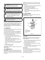
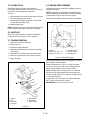
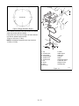
TABLE OF CONTENTS
Section 1 - Introduction . . . . . . . . . . . . . . . . .
1.1 The Manual . . . . . . . . . . . . . . . . . . . . . . .
1.2 Service and Replacement Parts . . . . . . .
1.3 Product Registration . . . . . . . . . . . . . . . .
1.4 Unauthorized Replacement Parts . . . . . .
1.5 Disclaimer . . . . . . . . . . . . . . . . . . . . . . . .
1.6 Technical Service Communications . . . . .
1-3
1-3
1-3
1-3
1-3
1-3
1-3
Section 2 - Safety2-4
2.1 Safety Alerts . . . . . . . . . . . . . . . . . . . . . .
2.2 Signal Words . . . . . . . . . . . . . . . . . . . . . .
2.3 Notations . . . . . . . . . . . . . . . . . . . . . . . . .
2.4 Practices and Laws . . . . . . . . . . . . . . . . .
2.5 Required Operator Training . . . . . . . . . . .
2.6 Preparation . . . . . . . . . . . . . . . . . . . . . . .
2.7 Service Position . . . . . . . . . . . . . . . . . . . .
2.8 Cleaning and Storage . . . . . . . . . . . . . . .
2.9 Safety Rules . . . . . . . . . . . . . . . . . . . . . .
Section 6 - Mower Deck . . . . . . . . . . . . . . . . .6-22
6.1 Rotary Mower Belt Replacement . . . . . . .6-22
6.2 Mower Drive Belt Replacement . . . . . . . .6-22
6.3 Mower Blade . . . . . . . . . . . . . . . . . . . . . .6-22
6.4 Mower Pan Removal . . . . . . . . . . . . . . . .6-23
6.5 Linkages for Mower Height/Engagement &
Clutch/Brake . . . . . . . . . . . . . . . . . . . . . . . . . .6-23
6.6 Mower Spindle Removal . . . . . . . . . . . . .6-25
2-4
2-4
2-4
2-4
2-4
2-4
2-4
2-4
2-5
Section 7 - Steering and Controls . . . . . . . . .7-26
7.1 Steering Shaft Gears . . . . . . . . . . . . . . . .7-26
7.2 Speed Selector . . . . . . . . . . . . . . . . . . . .7-27
Section 8 - Brake and Clutch . . . . . . . . . . . . .8-28
8.1 Brake Disassembly . . . . . . . . . . . . . . . . .8-28
8.2 Clutch and Brake Adjustment . . . . . . . . .8-28
Section 9 - Drive Train . . . . . . . . . . . . . . . . . .9-29
9.1 Rear Axle Disassembly . . . . . . . . . . . . . .9-29
9.2 Gear Case Removal . . . . . . . . . . . . . . . .9-29
9.3 Gear Case Replacement . . . . . . . . . . . . .9-30
9.4 Friction Wheel Replacement . . . . . . . . . .9-30
Section 3 - Specifications . . . . . . . . . . . . . . . 3-7
Section 4 - General Maintenance &
Adjustments. . . . . . . . . . . . . . . . . . . . . . . .4-12
4.1 Controls and Features . . . . . . . . . . . . . . .4-12
4.2 Service Positions . . . . . . . . . . . . . . . . . . .4-13
4.3 Filling The Fuel Tank . . . . . . . . . . . . . . . .4-13
4.4 General Lubrication . . . . . . . . . . . . . . . . .4-13
4.5 Mower Belt Adjustment . . . . . . . . . . . . . .4-14
4.6 Clutch and Brake . . . . . . . . . . . . . . . . . . .4-14
4.7 Mower Pan. . . . . . . . . . . . . . . . . . . . . . . .4-15
4.8 Anti-Scalp Rollers . . . . . . . . . . . . . . . . . .4-16
4.9 Vents . . . . . . . . . . . . . . . . . . . . . . . . . . . .4-16
4.10 Pinion and Steering Adjustment . . . . . .4-17
4.11 Tires . . . . . . . . . . . . . . . . . . . . . . . . . . . .4-17
Section 10 - Bagger. . . . . . . . . . . . . . . . . . . . 10-32
10.1 Vane Installation. . . . . . . . . . . . . . . . . . 10-32
10.2 Bagger Assembly. . . . . . . . . . . . . . . . . 10-32
10.3 Lower Boot Installation. . . . . . . . . . . . . 10-33
Section 11 - Electrical . . . . . . . . . . . . . . . . . .
11.1 Safety Interlock System . . . . . . . . . . . .
11.2 Troubleshooting . . . . . . . . . . . . . . . . . .
11.3 Battery (Electric Start Models) . . . . . . .
Section 5 - Engine. . . . . . . . . . . . . . . . . . . . . . 5-18
5.1 Engine Troubleshooting . . . . . . . . . . . . . . 5-18
5.2 Engine Oil . . . . . . . . . . . . . . . . . . . . . . . . 5-19
5.3 Changing Oil . . . . . . . . . . . . . . . . . . . . . . 5-19
5.4 Air Cleaner . . . . . . . . . . . . . . . . . . . . . . . .5-19
5.5 Spark Plug . . . . . . . . . . . . . . . . . . . . . . . .5-20
5.6 Muffler . . . . . . . . . . . . . . . . . . . . . . . . . . .5-20
5.7 Engine Removal . . . . . . . . . . . . . . . . . . .5-20
5.8 Engine Replacement . . . . . . . . . . . . . . . .5-20
2
11-34
11-34
11-34
11-34
SECTION 1 - INTRODUCTION
1.1 THE MANUAL
1.3 PRODUCT REGISTRATION
It is the purpose of this manual to provide complete
instructions for service, maintenance, disassembly,
repair, and installation of the mechanical components
for the 927 Rear Engine Rider Mowers.
A warranty registration card must be filled out, signed,
and returned at the time of purchase. This card
activates the warranty. Claims meeting requirements
during limited warranty period will be honored.
Dealer trained service personnel should use this
manual as a supplement to and reminder of the training
sessions conducted by the company.
1.4 UNAUTHORIZED REPLACEMENT
PARTS
Use only Ariens replacement parts. The replacement of
any part on this vehicle with anything other than an
Ariens authorized replacement part may adversely
affect the performance, durability, or safety of this unit
and may void the warranty. Ariens disclaims liability for
any claims or damages, whether warranty, property
damage, personal injury, or death arising out of the use
of unauthorized replacement parts.
Read all information for servicing a part of system
before repair work is started to avoid needless
disassembly.
Operation
Before operation of the unit, carefully and completely
read manuals supplied with the unit. The contents will
provide you with an understanding of safety
instructions and controls during normal operation and
maintenance.
1.5 DISCLAIMER
Directional Reference
Ariens reserves the right to discontinue, make changes
to, and add improvements upon its products at any
time without public notice or obligation. The
descriptions and specifications contained in this
manual were in effect at printing. Equipment described
within this manual may be optional. Some illustrations
may not be applicable to your unit.
All reference to left, right, front, or rear are given from
the operator in the operator position and facing the
direction of forward travel.
1.6 TECHNICAL SERVICE
COMMUNICATIONS
Safety Messages
For your safety and the safety of others always read,
understand, and follow all DANGER, WARNING, and
CAUTION messages found in manuals and on safety
decals.
1.2 SERVICE AND REPLACEMENT PARTS
When ordering publications, replacement parts, or
making service inquiries, know the Model and Serial
numbers of your unit and engine.
Numbers are located on the product registration form in
the unit literature package. They are printed on a serial
number label, located on the frame of your unit.
Serial Number
Figure 1
OA0040
3
Ariens Technical Service communicates information to
the field using Service Letters, Service Bulletins,
Product Notices, and Campaigns. Each
communication signifies a type of information and
priority. The dealer is responsible to carry out the
directive provided in the communication. The types of
communication are:
Service Letter - General technical information for the
dealer. Technical information on how to service the
product and product improvements.
Service Bulletin - Notification to update products to
resolve certain issues or a notification of a policy
change.
Product Notices - Notification of limited product
located in a certain region. This is a limited distribution
to only those who received the product involved.
Campaigns - Notification of a safety related issue. All
product must be updated and are tracked by the
factory until all units are corrected.
SECTION 2 - SAFETY
2.1 SAFETY ALERTS
2.6 PREPARATION
Look for these symbols to point out
important safety precautions. They
mean:
Before starting any removal of parts, proper
preparation is very important for efficient work. A clean
work area at the start of each job will allow you to
perform service repairs easily and quickly.
Attention!
Personal Safety Is Involved!
Become Alert!
Obey The Message!
To reduce the incidence of misplaced tools or parts,
place removed components with all attaching hardware
in the disassembly order on a clean work surface.
Organization is a key part of proper reassembly.
Tools, instruments, and parts needed for the job should
be gathered before work is started. Interrupting a job to
locate tools or parts is a needless delay. A list of
required special tools has been included in this
manual.
2.2 SIGNAL WORDS
The safety alert symbol is used in decals on the unit
and with proper operation procedures in this manual.
They alert you to the existence and relative degree of
hazards.
CAUTION: Remove enough fuel so that no
spillage will occur. Remove battery to prevent
spillage of electrolyte.
Understand the safety message. It contains important
information about personal safety on or near the unit.
DANGER: IMMINENTLY HAZARDOUS
SITUATION! If not avoided, WILL RESULT in
death or serious injury.
2.7 SERVICE POSITION
Place unit on a flat level surface. ALWAYS stop engine
and disengage clutches. Tip up on the service bar for
ease of access during some procedures. Assure unit is
secure and will not tip over. Strap and clamp onto lift if
used.
IMPORTANT: When unit is tipped up onto its service
bar, undrained gasoline drawn into cylinder may wash
cylinder wall and shorten engine life.
WARNING: POTENTIALLY HAZARDOUS
SITUATION! If not avoided, COULD RESULT
in death or serious injury.
CAUTION: POTENTIALLY HAZARDOUS
SITUATION! If not avoided, MAY RESULT in
minor or moderate injury. It may also be used
to alert against unsafe practices.
WARNING: AVOID SHARP EDGES which
can cut. Movement of parts can cut off fingers
or a hand. Wear gloves, and use extreme
caution when servicing.
2.3 NOTATIONS
NOTE: General reference information for proper operation and maintenance practices.
IMPORTANT: Specific procedures or information
required to prevent damage to unit or attachment.
2.4 PRACTICES AND LAWS
Practice usual and customary safe working
precautions, for the benefit of yourself and others.
Understand and follow all safety messages. Be alert to
unsafe conditions and the possibility of minor,
moderate, or serious injury or death. Learn applicable
rules and laws in your area.
2.8 CLEANING AND STORAGE
IMPORTANT: Never spray unit with water or store unit
outdoors to help prevent sealed bearing rust or
corrosion. Water can seep into sealed bearings and
reduce component life. Bearings are sealed against dirt
and debris only.
A unit that is excessively dirty should be cleaned
before work starts. Cleaning will occasionally uncover
trouble sources. Dirt and abrasive dust reduce the
efficient work life of parts and can lead to costly
replacement.
When taking unit out of extended storage:
2.5 REQUIRED OPERATOR TRAINING
Original purchaser of this unit was instructed by the
seller on safe and proper operation. If unit is to be used
by someone other than original purchaser; loaned,
rented or sold, ALWAYS provide this manual and any
needed safety training before operation.
2-4
1. Check for any damage or loose parts. Repair,
replace, or tighten hardware before operation.
2. If a preservative fluid was used in fuel tank, drain
and discard. Fill fuel tank with fresh new fuel.
2.9 SAFETY RULES
NO Flames!
Allow engine to cool before servicing.
NEVER fill fuel tank when engine is running, hot, or unit
is indoors.
Walk Around Inspection
Complete a walk around inspection of unit and work
area to understand:
Abnormal Vibrations are a warning of trouble. Striking a
foreign object can damage unit. Stop unit and engine.
Wait for all moving parts to stop. Remove wire from
spark plug. Inspect unit and make any necessary
repairs before restart.
• Work area.
• Your unit.
• All safety decals.
Work Area
ALWAYS check overhead and side clearances
carefully before operation. ALWAYS be aware of traffic
when operating along streets or curbs.
ALWAYS keep hands and feet within the limits of the
unit.
Hazardous Slopes
DO NOT operate on steep slopes. Avoid operating on
slopes. When you must operate on a slope, travel up
and down the slope. Never operate cross a slope.
Never operate on a slope greater than 10 degrees.
If tires lose traction, turn off auxiliary power and
proceed slowly straight down slope. Avoid wet
surfaces.
Keep children, people, and animals away. Keep
children out of work area and under watchful care of a
responsible adult.
Avoid parking on a slope. If necessary, use wheel
chocks.
Keep area of operation clear of all toys, pets, and
debris. Stay alert for hidden hazards.
DO NOT leave unit unattended on a slope. ALWAYS
use wheel chocks when leaving unit.
DO NOT run engine in an enclosed area. Always
provide good ventilation.
Child Safety
Unit
NEVER allow children to operate or play on or near
unit. Be alert and shut off unit if children enter area.
ALWAYS keep protective structures, guards, and
panels in good repair, in place and securely fastened.
NEVER modify or remove safety devices.
Personal Safety
Read and obey all warning, caution, and instructions
on the unit and in provided manuals.
Check Safety Interlock System for proper operation
daily (see Operation section). Do not operate unless
system operates properly.
• Only trained adults may operate unit.
Operation
• Training includes actual operation.
Understand:
• Clearly understand instructions.
• Be alert! Conditions can change.
• How to operate all controls
NEVER operate unit after or during the use of
medication, drugs or alcohol. Safe operation requires
your complete and unimpaired attention at all times.
• The functions of all controls
• How to STOP in an Emergency
• Speed ranges
NEVER allow anyone to operate the unit when their
alertness or coordination is impaired.
Before starting engine, disengage auxiliary power.
Always back up slowly. Always look down and behind
before and while backing.
DO NOT operate unit without wearing adequate outer
garments. Wear adequate safety gear and protective
gloves. Wear proper footwear to improve footing on
slippery surfaces.
Never leave a running unit unattended. ALWAYS shut
off auxiliary power, lower throttle setting, and stop
engine before leaving unit. ALWAYS remove key to
prevent unauthorized use.
Protect eyes, face, and head from objects that may be
thrown from unit. Wear appropriate hearing protection.
Never carry passengers on any part of unit.
Avoid uneven and rough terrain. DO NOT operate near
drop offs, ditches, or embankments. Unit can suddenly
turn over if a wheel is over the edge of a cliff or ditch, or
if an edge caves in.
ALWAYS operate unit in good visibility and light.
Fuel is highly flammable and its vapors can explode.
Use ONLY approved fuel containers.
NO Smoking!
NO Sparks!
Avoid Sharp Edges. Sharp edges can cut. Moving
parts can cut or amputate fingers or a hand. Wear
gloves to service unit when handling sharp edges.
ALWAYS keep hands away from any pinch points.
ALWAYS keep hands and feet away from all moving
parts during operation. Moving parts can cut off body
parts.
DO NOT touch unit parts which might be hot from
operation. Allow parts to cool before attempting to
maintain, adjust, or service.
2-5
Controls
Come to a complete stop before reversing.
Never jerk the control levers. Always use a steady
even action to achieve smooth control.
Always be aware of obstructions that may cause injury
to operator or damage to the unit.
Keep alert with eyes fixed in direction of travel.
Maintenance
ALWAYS maintain unit in safe operating condition.
Damaged or worn out muffler can cause fire or
explosion.
Check the condition of the unit at the end of each day
and repair any damage or defects.
ALWAYS block wheels and know all jack stands are
strong and secure and will hold weight of unit during
maintenance.
Keep nuts and bolts tight and keep equipment in safe
operating conditions.
Before maintenance, adjustments, or service (except
where specifically recommended), shut off engine.
Allow hot parts to cool.
Keep unit free of dirt, stones, and other debris. Clean
up oil or fuel spills.
Storage
DO NOT store unit inside a building with fuel in the fuel
tank where any ignition sources are present. Allow unit
to cool completely.
ALWAYS clean unit before extended storage. See
Engine Manual for proper storage.
Battery
Avoid Electric Shock. DO NOT reverse battery
connections.
Explosive Gases! Poisonous battery fluid contains
sulfuric acid and its contact with skin, eyes, or clothing
can cause severe burns.
No flames. No sparks. No smoking near battery.
Always wear safety glasses and protective gear near
battery.
DO NOT TIP battery beyond a 45o angle in any
direction.
ALWAYS KEEP BATTERIES OUT OF REACH of
children.
Transport
Use extra care when loading or unloading unit onto
trailer or truck. Secure unit chassis to transport vehicle.
NEVER secure from rods or linkages that could be
damaged.
Attachments and Accessories
Use only attachments or accessories designed for your
unit.
2-6
SECTION 3 - SPECIFICATIONS
Model Number
927046
927047
927048
927049
Description Name
RM 1028E
RM 1132E
RM 9028E
RM 9030E
180 CCA
180 CCA
180 CCA
180 CCA
Battery
Brakes
Drum
Drum
Drum
Drum
Gear & Pinion
Gear & Pinion
Gear & Pinion
Gear & Pinion
26 (66)
26 (66)
26 (66)
26 (66)
Front
4.10-3.50x4.00
4.10-3.50x4.00
4.10-3.50x4.00
4.10-3.50x4.00
Rear
16.6x5x8.00
16.6x5x8.00
16.6x5x8.00
16.6x5x8.00
Engine - Manufacturer
Briggs & Stratton
Briggs & Stratton
Briggs & Stratton
Briggs & Stratton
- Cycle
Four
Four
Four
Four
Steering
Turning Radius - in (cm)
Tire Size
- Horsepower
Starting System
Fuel Tank Cap. -qt (L)
Fuel
Idle RPM
Governed RPM
Crank Case Cap. - oz (L)
Air Cleaner
Engine Oil Type
Spark Plug
Transmission
Speed - Forward Max - mph (kph)
- Reverse Max. - mph (kph)
10.0
11.0
9.0
9.0
Electric
Electric
Electric
Electric
Recoil Back-up
Recoil Back-up
Recoil Back-up
Recoil Back-up
3 (2.8)
3 (2.8)
3 (2.8)
3 (2.8)
Unleaded
Unleaded
Unleaded
Unleaded
1800
1800
1800
1800
3250
3250
3250
3250
39 (1.2)
39 (1.2)
39 (1.2)
39 (1.2)
Paper Element
Paper Element
Paper Element
Paper Element
Foam Precleaner
Foam Precleaner
Foam Precleaner
Foam Precleaner
SAE 30
SAE 30
SAE 30
SAE 30
.030"
.030"
.030"
.030"
Sealed Case
Sealed Case
Sealed Case
Sealed Case
1.6-5.5 (2.6-8.8)
1.6-5.5 (2.6-8.8)
1.6-5.5 (2.6-8.8)
1.6-5.5 (2.6-8.8)
2.7 (4.3)
2.7 (4.3)
2.7 (4.3)
2.7 (4.3)
Transmission Lube
150 Grease
150 Grease
150 Grease
150 Grease
Drive Clutch
Disc-O-Matic
Disc-O-Matic
Disc-O-Matic
Disc-O-Matic
Front
14 PSI
14 PSI
14 PSI
14 PSI
Rear
14 PSI
14 PSI
14 PSI
14 PSI
Lift System
Manual
Manual
Manual
Manual
Power Take Off
Manual
Manual
Manual
Manual
Standard
Standard
Standard
Standard
Standard
Standard
Standard
Standard
Tire Pressure
Mower Deck - Flex & Float
- High Performance
- Cutting Width - in (cm)
28 (71.1)
32 (81.3)
28 (71.1)
30 (76.2)
- Cutting Height - in (cm)
1.5-3.5 (3.8-11.4)
1.5-3.5 (3.8-11.4)
1.5-3.5 (3.8-11.4)
1.5-3.5 (3.8-11.4)
- Cut Increments - in (cm)
.5 (1.2)
.5 (1.2)
.5 (1.2)
.5 (1.2)
827026/827013
827026/827013
827026/827013
827020
Dethatcher Kit
72701300
72701300
72701300
72701300
Front Weight Kit
72701600
72701600
72701600
72701600
Bagger
Leaf Mulcher Kit
Grass Mulcher Kit
N/A
N/A
N/A
72703400
72703500
72703600
72703500
72701400
3-7
Model Number
927050
927051
927052
927053
Description Name
RM 1232E
RM 1332
RM 1330
RM 9028
Battery
180 CCA
180 CCA
180 CCA
180 CCA
Brakes
Drum
Drum
Drum
Drum
Gear & Pinion
Gear & Pinion
Gear & Pinion
Gear & Pinion
26 (66)
26 (66)
26 (66)
26 (66)
4.10-3.50x4.00
4.10-3.50x4.00
4.10-3.50x4.00
4.10-3.50x4.00
Steering
Turning Radius - in (cm)
Tire Size
Front
Rear
16.6x5x8.00
16.6x5x8.00
16.6x5x8.00
16.6x5x8.00
Engine - Manufacturer
Briggs & Stratton
Briggs & Stratton
Briggs & Stratton
Briggs & Stratton
- Cycle
Four
Four
Four
Four
- Horsepower
Starting System
Fuel Tank Cap. -qt (L)
Fuel
Idle RPM
Governed RPM
Crank Case Cap. - oz (L)
Air Cleaner
Engine Oil Type
Spark Plug
Transmission
Speed - Forward Max - mph (kph)
- Reverse Max. - mph (kph)
12.0
13.0
13.0
9.0
Electric
Electric
Electric
Electric
Recoil Back-up
Recoil Back-up
Recoil Back-up
Recoil Back-up
3 (2.8)
3 (2.8)
3 (2.8)
3 (2.8)
Unleaded
Unleaded
Unleaded
Unleaded
1800
1800
1800
1800
3250
3250
3250
3250
39 (1.2)
39 (1.2)
39 (1.2)
39 (1.2)
Paper Element
Paper Element
Paper Element
Paper Element
Foam Precleaner
Foam Precleaner
Foam Precleaner
Foam Precleaner
SAE 30
SAE 30
SAE 30
SAE 30
.030"
.030"
.030"
.030"
Sealed Case
Sealed Case
Sealed Case
Sealed Case
1.6-5.5 (2.6-8.8)
1.6-5.5 (2.6-8.8)
1.6-5.5 (2.6-8.8)
1.6-5.5 (2.6-8.8)
2.7 (4.3)
2.7 (4.3)
2.7 (4.3)
2.7 (4.3)
Transmission Lube
150 Grease
150 Grease
150 Grease
150 Grease
Drive Clutch
Disc-O-Matic
Disc-O-Matic
Disc-O-Matic
Disc-O-Matic
Front
14 PSI
14 PSI
14 PSI
14 PSI
Rear
14 PSI
14 PSI
14 PSI
14 PSI
Manual
Manual
Manual
Manual
Tire Pressure
Lift System
Power Take Off
Mower Deck - Flex & Float
- High Performance
Manual
Manual
Manual
Manual
Standard
Standard
Standard
Standard
Standard
Standard
Standard
Standard
- Cutting Width - in (cm)
32 (81.3)
32 (81.3)
30 (76.2)
28 (71.1)
- Cutting Height - in (cm)
1.5-3.5 (3.8-11.4)
1.5-3.5 (3.8-11.4)
1.5-3.5 (3.8-11.4)
1.5-3.5 (3.8-11.4)
- Cut Increments - in (cm)
.5 (1.2)
.5 (1.2)
.5 (1.2)
.5 (1.2)
Bagger
827026/827013
827026/827013
827020
827026/827013
Dethatcher Kit
72701300
72701300
72701300
72701300
Front Weight Kit
72701600
72701600
72701600
72701600
N/A
N/A
72703400
N/A
72703600
72703600
72701400
72703500
Leaf Mulcher Kit
Grass Mulcher Kit
3-8
Model Number
927054
927055
927056
927301
Description Name
RM 9030
RM 1332
RM 1330
RM 9028E
Battery
180 CCA
180 CCA
180 CCA
180 CCA
Brakes
Drum
Drum
Drum
Drum
Gear & Pinion
Gear & Pinion
Gear & Pinion
Gear & Pinion
26 (66)
26 (66)
26 (66)
26 (66)
4.10-3.50x4.00
4.10-3.50x4.00
4.10-3.50x4.00
4.10-3.50x4.00
Steering
Turning Radius - in (cm)
Tire Size
Front
Rear
16.6x5x8.00
16.6x5x8.00
16.6x5x8.00
16.6x5x8.00
Engine - Manufacturer
Briggs & Stratton
Briggs & Stratton
Briggs & Stratton
Briggs & Stratton
- Cycle
Four
Four
Four
Four
- Horsepower
Starting System
Fuel Tank Cap. -qt (L)
Fuel
Idle RPM
Governed RPM
Crank Case Cap. - oz (L)
Air Cleaner
Engine Oil Type
Spark Plug
Transmission
Speed - Forward Max - mph (kph)
- Reverse Max. - mph (kph)
9.0
13.0
13.0
9.0
Electric
Electric
Electric
Electric
Recoil Back-up
Recoil Back-up
Recoil Back-up
Recoil Back-up
3 (2.8)
3 (2.8)
3 (2.8)
3 (2.8)
Unleaded
Unleaded
Unleaded
Unleaded
1800
1800
1800
1800
3000 max.
3250
3250
3250
39 (1.2)
39 (1.2)
39 (1.2)
30 (.9)
Paper Element
Paper Element
Paper Element
Paper Element
Foam Precleaner
Foam Precleaner
Foam Precleaner
Foam Precleaner
SAE 30
SAE 30
SAE 30
SAE 30
.030"
.030"
.030"
.030"
Sealed Case
Sealed Case
Sealed Case
Sealed Case
1.6-5.5 (2.6-8.8)
1.6-5.5 (2.6-8.8)
1.6-5.5 (2.6-8.8)
1.5-5.1 (2.4-8.2)
2.7 (4.3)
2.7 (4.3)
2.7 (4.3)
2.5 m(4.0)
Transmission Lube
150 Grease
150 Grease
150 Grease
150 Grease
Drive Clutch
Disc-O-Matic
Disc-O-Matic
Disc-O-Matic
Disc-O-Matic
Front
14 PSI
14 PSI
14 PSI
14 PSI
Rear
14 PSI
14 PSI
14 PSI
14 PSI
Manual
Manual
Manual
Manual
Tire Pressure
Lift System
Power Take Off
Mower Deck - Flex & Float
- High Performance
Manual
Manual
Manual
Manual
Standard
Standard
Standard
Standard
Standard
Standard
Standard
Standard
- Cutting Width - in (cm)
30 (76.2)
32 (81.3)
30 (76.2)
28 (71.1)
- Cutting Height - in (cm)
1.5-3.5 (3.8-11.4)
1.5-3.5 (3.8-11.4)
1.5-3.5 (3.8-11.4)
1.5-3.5 (3.8-11.4)
- Cut Increments - in (cm)
.5 (1.2)
.5 (1.2)
.5 (1.2)
.5 (1.2)
Bagger
827020
827026/827013
827020
827026/827013
Dethatcher Kit
72701300
72701300
72701300
72701300
Front Weight Kit
72701600
72701600
72701600
72701600
Leaf Mulcher Kit
72703400
N/A
72703400
N/A
Grass Mulcher Kit
72701400
72703600
72701400
72703500
3-9
Model Number
927302
927303
927304
927305
Description Name
RM 1228E
RM 1232E
RM 1328
RM 1332
Battery
180 CCA
180 CCA
180 CCA
180 CCA
Brakes
Drum
Drum
Drum
Drum
Gear & Pinion
Gear & Pinion
Gear & Pinion
Gear & Pinion
26 (66)
26 (66)
26 (66)
26 (66)
4.10-3.50x4.00
4.10-3.50x4.00
4.10-3.50x4.00
4.10-3.50x4.00
Steering
Turning Radius - in (cm)
Tire Size
Front
Rear
16.6x5x8.00
16.6x5x8.00
16.6x5x8.00
16.6x5x8.00
Engine - Manufacturer
Briggs & Stratton
Briggs & Stratton
Briggs & Stratton
Briggs & Stratton
- Cycle
Four
Four
Four
Four
- Horsepower
Starting System
Fuel Tank Cap. -qt (L)
Fuel
Idle RPM
Governed RPM
Crank Case Cap. - oz (L)
Air Cleaner
Engine Oil Type
Spark Plug
Transmission
Speed - Forward Max - mph (kph)
- Reverse Max. - mph (kph)
12.0
12.0
13.0
13.0
Electric
Electric
Electric
Electric
Recoil Back-up
Recoil Back-up
Recoil Back-up
Recoil Back-up
3 (2.8)
3 (2.8)
3 (2.8)
3 (2.8)
Unleaded
Unleaded
Unleaded
Unleaded
1800
1800
1800
1800
2930 max.
2850 max.
3250
3250 max.
39 (1.2)
39 (1.2)
39 (1.2)
39 (1.2)
Paper Element
Paper Element
Paper Element
Paper Element
Foam Precleaner
Foam Precleaner
Foam Precleaner
Foam Precleaner
SAE 30
SAE 30
SAE 30
SAE 30
.030"
.030"
.030"
.030"
Sealed Case
Sealed Case
Sealed Case
Sealed Case
1.4-5.0 (2.3-8.0)
1.4-4.8 (2.3-7.7)
1.6-5.5 (2.6-8.8)
1.6-5.5 (2.6-8.8)
2.4 (3.9)
2.4 (3.9)
2.7 (4.3)
2.7 (4.3)
Transmission Lube
150 Grease
150 Grease
150 Grease
150 Grease
Drive Clutch
Disc-O-Matic
Disc-O-Matic
Disc-O-Matic
Disc-O-Matic
Front
14 PSI
14 PSI
14 PSI
14 PSI
Rear
14 PSI
14 PSI
14 PSI
14 PSI
Manual
Manual
Manual
Manual
Tire Pressure
Lift System
Power Take Off
Mower Deck - Flex & Float
- High Performance
Manual
Manual
Manual
Manual
Standard
Standard
Standard
Standard
Standard
Standard
Standard
Standard
- Cutting Width - in (cm)
28 (71.1)
32 (81.3)
28 (71.1)
32 (81.3)
- Cutting Height - in (cm)
1.5-3.5" (3.8-11.4)
1.5-3.5" (3.8-11.4)
1.5-3.5" (3.8-11.4)
1.5-3.5" (3.8-11.4)
- Cut Increments - in (cm)
.5 (1.2)
.5 (1.2)
.5 (1.2)
.5 (1.2)
Bagger
827026/827013
827026/827013
827026/827013
827026/827013
Dethatcher Kit
72701300
72701300
72701300
72701300
Front Weight Kit
72701600
72701600
72701600
72701600
Leaf Mulcher Kit
Grass Mulcher Kit
N/A
N/A
N/A
N/A
72703500
72703600
72703500
72703600
3 - 10
Model Number
927306
927307
927308
927310
Description Name
RM 9028
RM 1328
RM 1332
RM 1028
Battery
180 CCA
180 CCA
180 CCA
180 CCA
Brakes
Drum
Drum
Drum
Drum
Gear & Pinion
Gear & Pinion
Gear & Pinion
Gear & Pinion
26 (66)
26 (66)
26 (66)
26 (66)
4.10-3.50x4.00
4.10-3.50x4.00
4.10-3.50x4.00
4.10-3.50x4.00
Steering
Turning Radius - in (cm)
Tire Size
- Front
- Rear
16.6x5x8.00
16.6x5x8.00
16.6x5x8.00
16.6x5x8.00
Engine - Manufacturer
Briggs & Stratton
Briggs & Stratton
Briggs & Stratton
Briggs & Stratton
- Cycle
Four
Four
Four
Four
- Horsepower
Starting System
Fuel Tank Cap. -qt (L)
Fuel
Idle RPM
Governed RPM
Crank Case Cap. - oz (L)
Air Cleaner
Engine Oil Type
Spark Plug
Transmission
Speed - Forward Max - mph (kph)
- Reverse Max. - mph (kph)
9.0
13.0
13.0
10.0
Electric
Electric
Electric
Electric
Recoil Back-up
Recoil Back-up
Recoil Back-up
Recoil Back-up
3 (2.8)
3 (2.8)
3 (2.8)
3 (2.8)
Unleaded
Unleaded
Unleaded
Unleaded
1800
1800
1800
1800
3250
3250
3250
3250
39 (1.2)
39 (1.2)
39 (1.2)
39 (1.2)
Paper Element
Paper Element
Paper Element
Paper Element
Foam Precleaner
Foam Precleaner
Foam Precleaner
Foam Precleaner
SAE 30
SAE 30
SAE 30
SAE 30
.030"
.030"
.030"
.030"
Sealed Case
Sealed Case
Sealed Case
Sealed Case
1.6-5.5 (2.6-8.8)
1.6-5.5 (2.6-8.8)
1.6-5.5 (2.6-8.8)
1.6-5.5 (2.6-8.8)
2.7 (4.3)
2.7 (4.3)
2.7 (4.3)
2.7 (4.3)
Transmission Lube
150 Grease
150 Grease
150 Grease
150 Grease
Drive Clutch
Disc-O-Matic
Disc-O-Matic
Disc-O-Matic
Disc-O-Matic
Front
14 PSI
14 PSI
14 PSI
14 PSI
Rear
14 PSI
14 PSI
14 PSI
14 PSI
Manual
Manual
Manual
Manual
Tire Pressure
Lift System
Power Take Off
Mower Deck - Flex & Float
- High Performance
Manual
Manual
Manual
Manual
Standard
Standard
Standard
Standard
Standard
Standard
Standard
Standard
- Cutting Width - in (cm)
28 (71.1)
28 (71.1)
32 (81.3)
28 (71.1)
- Cutting Height - in (cm)
1.5-3.5 (3.8-11.4)
1.5-3.5 (3.8-11.4)
1.5-3.5 (3.8-11.4)
1.5-3.5 (3.8-11.4)
- Cut Increments - in (cm)
.5 (1.2)
.5 (1.2)
.5 (1.2)
.5 (1.2)
Bagger
827026/827013
827026/827013
827026/827013
827026/827013
Dethatcher Kit
72701300
72701300
72701300
72701300
Front Weight Kit
72701600
72701600
72701600
72701600
Leaf Mulcher Kit
Grass Mulcher Kit
N/A
N/A
N/A
N/A
72703500
72703500
72703600
72703500
3 - 11
SECTION 4 - GENERAL MAINTENANCE & ADJUSTMENTS
4.1 CONTROLS AND FEATURES
4
5
3
6
CAUTION
CA
UTION
Before starting engine be
sure machine is in neutral
and mower clutch is
disengaged
2
P
Depress clutch pedal
and push latch to set.
7
WARNING
TO AVOID SERIOUS INJURY
OR DEATH
Read operator's manual.
Understand location and
function of all controls.
Look down and behind before
and while backing.
Remove objects thatcould be thrown
by the blade.
Avoid sudden turns.
Check interlock system per manual
before use.
Keep all sheilds in place.
Never carry childern.
Keep people and pets away when operating
machine.
Go up and down slopes, not across.
If machine stops going uphill. shut off
PTO and back down slowly.
1
GO
Release parking brake
Depress clutch pedal
Shift to 1st or 2nd speed
Slowly release clutch
Shift to desired speed
6
5
4
3
2
1
N
8
R
STOP
Depress clutch pedal
Speed
Selector
Depress Brake pedal
Before leaving operator's
position:
Shift to neutral
Engage parking brake
Disengage mower clutch
Stop Engine
Remove ignition key
Located on
r ight hand
side of
dr iver's seat
SERVICING
Wait for all movement to stop
Disconnect spark plug wire
Before tipping unit, drain
gas tank and remove
battery - if electric
10
11
9
12
13
1.
2.
3.
4.
5.
6.
7.
Throttle Control
Mower Clutch Lever
Parking Brake
Clutch Pedal
Brake Pedal
Mower Height Lever
Ignition Key Switch
8. Speed Indicator
9. Speed Selector
10.Engine Oil Fill
11.Fuel Tank Fill
12.Mower Pan
13.Roller
Figure 2
4 - 12
OS0792
4.2 SERVICE POSITIONS
Ariens Dealers will provide any service or adjustments
which may be required to keep your unit operating at
peak efficiency. Should engine service be required,
contact an Ariens dealer or an authorized engine
manufacturer’s service center.
WARNING: ACCIDENTAL ENGINE START
UP can cause death or serious injury.
ALWAYS stop engine, remove key, wait for
moving parts to stop and remove wire from
spark plug before adjusting or servicing.
HOT SURFACES can result in death or
serious injury.
DO NOT touch parts which are hot from
operation.
ALWAYS allow parts to cool.
1
2
6
5
3
4
1. Oil Fill Cap and Dipstick
2. Air Cleaner Cover
3. Spark Plug
4. Oil Drain Plug
5. Fuel Tank
6. Fuel Cap
Figure 3
ROTATING PARTS can cut off body parts.
Keep hands and feet away. Loose clothing,
long hair or scarves can get caught in rotating
parts and cause death or serious injury.
4. Remove cap.
IMPORTANT: DO NOT use gasohol or gasoline
containing alcohol. Alcohol will cause internal parts to
deteriorate. See Engine Manual for correct type and
grade of fuel.
CAUTION: FUEL SPILLS may result in minor
or moderate injury and/or damage to the unit.
Before unit is tipped up onto housing, remove
enough fuel so that no spillage will occur.
Remove battery to prevent spillage of
electrolyte.
5. Fill fuel tank to within 1/2" (1.3 cm) below bottom of
filler neck with unleaded gasoline.
6. Replace fuel cap and tighten.
7. ALWAYS clean up any spilled fuel.
Maintenance Schedule
Service Position
Place unit on a flat level surface. ALWAYS stop engine
and disengage clutches. Tip up on the service bar for
ease of access during some procedures. Assure unit is
secure and will not tip over. Strap and clamp onto lift if
used.
When unit is tipped up onto its service bar, undrained
gasoline drawn into cylinder may wash cylinder wall
and shorten engine life.
The chart below shows the recommended
maintenance schedule that should be performed on a
regular basis. More frequent service may be required
due to working conditions (heavy loads, high ambient
temperatures, dusty conditions, or airborne debris).
See Engine Manual for further maintenance and
troubleshooting information.
4.4 GENERAL LUBRICATION
IMPORTANT: Wipe each grease fitting clean before
and after lubrication. Keep grease and oil off belts to
avoid slippage and deterioration.
NOTE: Apply Sten Mix Hi-Temp Grease or equivalent
to the lube fittings. Order P/N: 00036800 - three pack of
3 oz. cartridges or 00036700 - ten pack of 14 oz.
cartridges.
4.3 FILLING THE FUEL TANK
FLAMMABLE FUEL and its EXPLOSIVE
VAPORS can result in death or serious injury.
Handle fuel with care. ALWAYS use an
approved fuel container.
No Smoking! No lighted Materials!
The steering system, front wheels, left rear wheel and
linkage pivot points should be lubricated every
25 hours of operation, or twice each season,
whichever occurs first (Figure 4).
No Open Flame!
Allow engine to cool before any service.
To add fuel to fuel tank (Figure 3):
1. ALWAYS place unit in open or well ventilated area.
2. Stop engine and allow to cool for 2 minutes.
3. Clean fuel cap and surrounding area to prevent dirt
from entering fuel tank.
4 - 13
4
3
5
2
6
1
1.
2.
3.
4.
Steering Gear
Adjustment Cap Screw
Height Control
Height Lever
5. View Quadrant Through
Slot
6. Spring Clip
Figure 5
Figure 4
4
3
4.5 MOWER BELT ADJUSTMENT
Adjust mower belt after first five (5) hours of operation.
To adjust 28" and 30" mowers (Figure 5):
6
1. Place height control lever in midnotch position,
depress spring clip and tighten yoke on front of unit
with a 3/4" socket wrench.
2
2. When tightening cap screw, hold mower clutch
lever so that front edge of lever is positioned in line
with rear edge of forward notch of quadrant.
3. Tighten belt just enough to prevent slippage under
load. Mower clutch lever (when tightening cap
screw) will move slightly to rear of this point when
tension is correct.
1
5
1. Mower Pulley
2. Mower Belt
3. Fixed Idler
4. Clutching Idler
5. Belt Finger
6. Adjustable Clutch Rod
Figure 6
To adjust the 32" mower:
1. The 32" mower belt clutch rod should be adjusted
so the compressed spring length is from 5-1/4" to
5-3/8" (13.3 to 13.6 cm) when belt is engaged
(Figure 6).
4.6 CLUTCH AND BRAKE
2. Belt engagement should occur when front edge of
mower clutch is positioned in line with rear edge of
forward notch of quadrant (as viewed through slot
in left side of cowl).
3. Full locked-in engagement should occur when
lever is positioned completely into front notch of
quadrant. (Some resistance should be felt when
moving lever into notch).
Clutch and brake adjustments are dependent upon
each other. If depressing clutch and brake pedal fully
does not stop riding mower and/or hold it on hill, brake
must be adjusted.
1. With speed selector in neutral (N), depress clutch
pedal fully and engage parking brake.
2. Adjust double nuts on clutch rod until carrier yoke
clears neutral stop by 1/8" to 1/4" (3.18 to 6.4 mm).
4 - 14
3. Release parking brake and turn both rear wheels
by hand. They should rotate freely in neutral (N)
but not rotate with speed selector in any other
position.
2
4. Using two 1/2" wrenches (to avoid twisting or
distorting brake band), hold inner adjusting nut with
one wrench and loosen outer lock nut with the
other.
1
3
5. Turn rear wheel by hand while tightening inner
adjustment nut until brake band just binds on hub.
Back off adjusting nut by 1-1/2 turns and secure
with locknut.
6. Test by fully depressing clutch pedal and trying to
turn wheels by hand. They should not turn.
5
1
2
1. Adjustment Cap Screw
2. Adjustment Level
3. Mower Pan
Figure 8
3
4
Cutting Height
6
CAUTION: Rotate mower blade with mower
clutch disengaged (OUT) and take
measurements with mower clutch engaged
(ON).
Cutting height range is 1" to 4" (2.5 to 10.1 cm). Place
unit on a smooth, flat, level surface.
1. With blade (s) positioned side to side, measure
distance of blade(s) tips to floor at right and left
side of mower pan (Figures 8 and 9).
1. Neutral Stop
2. Brake Rod
3. Clutch Rod
2. Rotate blade(s) 180o and check again. The
measurement should be equal within 1/8" (3.2 mm)
side to side.
4. Clutch Adjustment Nuts
5. Brake Adjustment Nuts
6. Brake Band
To correct for difference in height of blade tips from
side to side:
Figure 7
1. Loosen nuts on adjustment levers.
2. Turn lever adjustment screw clockwise on the low
side of mower pan to raise the low side to one half
the difference in height.
4.7 MOWER PAN
Mower Level (Side to Side)
NOTE: A wood block (about 1" square by 5" long) may
be used under pan for blade measurement. Wrap block
with masking tape, mark tape with cutting edge of
blade and measure distance from end of block to
mark(s). This method avoids errors by having to read
any measurements under pan.
3. Turn lever adjustment screw counterclockwise on
the high side to lower high side the remaining one
half of the height difference.
4. Tighten nuts on adjustment levers.
3
2
1
To level mower pan, turn adjustment cap screw on
adjustment lever clockwise to raise right side or
counterclockwise to lower it (Figure 8).
4
6
5
1. Cutting Tip
2. Mower Pan
3. Blade
4. Ground Level
5. Cutting Height
6. Discharge Chute
Figure 9
4 - 15
OT0860
Mower Pitch and Height
Proper blade pitch is when the blade tip, measured
from the bottom surface (Figure 10), is 1/4" to 3/8"
(6.4 to 9.9 mm) lower at front of mower pan than when
same tip is at rear of mower pan.
2
3
2. Slide lift strap and adjustment strap together to
raise, or apart to lower rear of pan.
4.8 ANTI-SCALP ROLLERS
Secure rollers in middle position for average lawn
mowing.
Front of Unit
1.
2.
3.
4.
1. Loosen nut on carriage bolt and remove cap screw
holding lift strap and adjustment strap together.
3. Select tapped hole in lift strap that provides proper
adjustment, install cap screw in tapped hole and
tighten nut on carriage bolt to secure.
1
4
If proper pitch cannot be obtained with front and rear lift
links:
Blade Cutting Edges
Ground Level
Front Blade Height
Rear Blade Height
1. Use lowest roller position when mowing in higher
cutting heights and rough terrain to guard against
most scalping.
Figure 10
2. Use highest roller position when cutting at lowest
cutting height.
OT0850
Adjusting front lift link raises or lowers front of mower
pan and changes both cutting height and pitch.
To adjust:
1. Loosen jam nut on front link to allow for movement
of coupling nut.
2. Turn coupling nut clockwise to raise and
counterclockwise to lower front of mower pan.
3. Secure coupling in position by tightening jam nut.
For smoothest appearing cut when using frame
suspended models with anti-scalp rollers, keep antiscalp rollers adjusted to the minimum 1/2" (12.8 mm)
above flat hard smooth surface after setting height of
cut.
NOTE: The rollers are intended for anti-scalping, not
for controlling cutting height.
4.9 VENTS
Adjusting rear lift links raises or lowers rear of mower
pan and changes both cutting height and pitch.
The vents are opened at the factory to increase airflow
into deck for bagging purposes. To open, align the
vents on deck with spindle housing holes (Figure 12).
To adjust:
1. Loosen both lower jam nuts to allow for movement
of upper jam nuts on lift rods.
Vents
2. Turn both upper jam nuts on each lift rod equality
to raise or lower rear of pan.
3. Secure lift rods in position by tightening lower jam
nuts.
3
4
1
2
Figure 12
1. Lift Strap
2. Cap Screw-Remove to
Adjust
3. Carriage Bolt
4. Adjustment Strap
Figure 11
4 - 16
4.10 PINION AND STEERING
ADJUSTMENT
For ease of access to bottom of unit during service
procedures, your unit may be driven up on ramps or
tipped up onto bagger attachment service bar and
braced securely. (For units without a bagger
attachment, a service bar package is available through
your Ariens Dealer.)
On units with steering adjustment bracket, loosen
lower lock nut and tighten adjustment nut until steering
works smoothly with no play in gears.
Tighten lower lock nut.
2
1
3
1. Bottom of Steering Post
2. Adjustment Nut
3. Lock Nut
Figure 13
4.11 TIRES
NOTE: Keep tires properly inflated at all times. For
proper tire inflation when working under various conditions inflate tires to 14 psi. Use a low pressure tire
gauge for accurate pressure readings.
4 - 17
SECTION 5 - ENGINE
5.1 ENGINE TROUBLESHOOTING
The following troubleshooting chart is to be used to
isolate engine problems and give possible causes and
corrective action responses.
TROUBLE
Black Exhaust
Blue/White Exhaust
Difficult Starting
Erratic Running
Excessive Fuel Consumption
High Oil Pressure
Knocking
Loss of Power or System
Low Cranking Power
Low Oil Pressure
Misfiring
Overheating
Poor Compression
Starts and Stops
The troubleshooting key is generic and can be used for
several types of engines. Use only those possible
causes and corrective actions that apply to the
unit.
POSSIBLE CAUSES
CORRECTIVE ACTION
(Refer to Key Below)
1, 20, 22, 25, 29, 31, 32, 33
4, 20, 25, 31, 33, 34
1, 5, 7, 8, 9, 10, 20, 21, 22, 29, 31, 32, 33
1, 7, 8, 9, 10, 20, 21, 23, 26, 29, 33, 59, 62
1, 20, 22, 23, 25, 39, 31, 32, 33
4, 41
22, 26, 29, 31, 33, 36, 46, 59
1, 8, 10, 20, 21, 22, 23, 25, 26, 31, 32, 33
2, 3, 4, 11
4, 36, 37, 39
10, 20, 25, 26, 28, 29, 32
1, 19, 25,
25, 28, 29, 31, 32, 33, 34,59,
1, 6, 10, 62
repair or replace
repair or replace
repair or replace
repair or replace
repair or replace
repair or replace
repair or replace
repair or replace
repair or replace
repair or replace
repair or replace
repair or replace
repair or replace
repair or replace
see electrical systems
Vibration
Will Not Crank
Will Not Start
see engine service manual
repair or replace
charge battery or replace
repair or replace
20, 23, 25, 26, 29, 33, 45, 49
2, 11, 45
1, 10, 62
see electrical systems
see engine service manual
TROUBLESHOOTING KEY
1
2
3
4
5
6
7
22
23
24
25
26
27
28
Incorrect grade of fuel
Sticking throttle/restricted movement
Exhaust pipe restriction
Leaking cylinder head gasket
Overheating
Cold running
Incorrect tappet adjustment
43
44
45
46
47
48
49
29
30
31
32
33
34
35
Sticking valves
Incorrect high pressure pipes
Worn cylinder bores
Pitted valves and seats
Broken, worn or sticking piston ring(s)
Worn valve stems and guides
Restriction in air cleaner
50
51
52
53
54
55
56
36
Worn or damaged bearings
57
16
17
18
19
Incorrect use of cold start
equipment
Faulty cold start equipment
Broken fuel injection pump drive
Incorrect fuel pump timing
Incorrect valve timing
37
38
39
40
Insufficient oil in sump
Bad/defective oil temperature switch
Oil pump worn
Pressure relief valve sticking open
58
59
60
61
20
21
Poor compression
Blocked fuel tank vent
41
42
Pressure relief valve sticking closed
Broken relief valve spring
62
8
9
10
11
12
13
14
15
Restriction in air cleaner
Bad electrical connection
Faulty starter motor
Incorrect grade of lubricating oil
Low cranking speed
Fuel tank empty
Controls not in correct operation
position
Blocked fuel feed line
Faulty fuel lift pump
Choked fuel filter
Battery capacity low
Air in fuel system
Faulty fuel injection pump
Faulty fuel injectors or incorrect type
5 - 18
Faulty suction pipe
Choked oil filter
Bad solenoid switch
Incorrect piston height
Damaged fan
Faulty engine mounting
Incorrectly aligned flywheel and/or
flywheel housing
Faulty thermostat
Restriction in water jacket
Loose fan belt
Choked radiator
Faulty water pump
Choked breather pipe
Damaged valve stem oil deflector (if
fitted)
Coolant level too low
Blocked sump strainer
Broken valve spring
Exhaust or vacuum pipe leak
Bad or defective water temperature
switch
Bad spark plug(s)
NOTE: Run engine just prior to changing oil. Oil will
flow more freely and carry away more contamination
when warm.
WARNING: Stop engine, remove key and
wait for moving parts to stop before
attempting any service procedures.
1. Drain engine crankcase by removing oil drain plug.
After oil has drained, replace plug.
2. Remove oil fill cap and dipstick.
CAUTION: DO NOT touch engine or riding
mower parts which are hot from operation.
Allow such parts to cool before servicing unit.
3. Pouring slowly, fill crankcase with oil. (See
specifications).
4. Check oil level with dipstick. Replace dipstick and
retighten cap.
CAUTION: DO NOT tip unit up onto service
bar without draining enough gasoline from
tank to avoid spilling gasoline. On electric
start models, remove battery to prevent
spillage of electrolyte.
5.4 AIR CLEANER
IMPORTANT: Never run engine without complete air
cleaner installed on engine.
WARNING: Gasoline is highly flammable and
must be handled with care.
1
For ease of access to bottom of unit during service
procedures, your riding mower may be driven up on
ramps or tipped up onto bagger attachment service bar
and braced securely. (For units without a bagger
attachment, a service bar package is available through
your Ariens Dealer).
2
3
4
5.2 ENGINE OIL
See engine manufacturer’s instructions for proper type,
viscosity and amount required.
1.
2.
3.
4.
The engine crankcase oil should be checked daily or
every five (5) hours of operation. Oil level MUST be
maintained in safe operating range on dipstick at all
times or engine damage will result.
Cover
Filter Element
Paper Element
Body
Figure 14
1. Clean all debris away from around oil cap.
Foam Filter
2. Remove oil cap and dipstick. Wipe oil off dipstick
with a clean cloth.
Inspect filter every twenty-five (25) operating hours
(more often if unit is used under extremely dirty or
dusty conditions).
3. Replace dipstick until cap bottoms on tube.
Remove dipstick again and observe oil level. Oil
should be at the Full (F) mark.
4. If low, add oil and bring up to the Full (F) mark. DO
NOT over fill. Oil level must not exceed Full (F)
mark.
5. Replace dipstick and cap.
6. Clean up any spilled oil.
IMPORTANT: DO NOT overfill. Be sure engine is level
when adding oil.
5.3 CHANGING OIL
IMPORTANT: Change engine crankcase oil after first
two (2) hours of operation. Thereafter, change oil every
twenty five hours of operation (more often in dusty dirty
conditions).
1. Wash in water and detergent solution and squeeze
(don’t twist) until all dirt is removed.
2. Rinse thoroughly in clear water.
3. Wrap in a clean cloth and squeeze (do not twist)
until completely dry.
4. Saturate with engine oil and squeeze (do not twist)
to distribute oil and remove excess oil.
Paper Filter
Do not attempt to clean or oil filter. Replace once a
year or every 100 operating hours, more often if used
in extremely dusty conditions.
Clean inside of cover and body of filter holder. Replace
filter and cover and secure.
5 - 19
5.5 SPARK PLUG
5.8 ENGINE REPLACEMENT
Spark plug should be cleaned or replaced (if
necessary) and gap reset to .030" every 100 hours of
operation or yearly whichever comes first.
1. Remove debris from area around spark plug base.
Consult parts manual to determine hardware used on
replacement engine.
NOTE: Depending on horsepower and manufacturer,
various bolt patterns and amounts of hardware (taptites
or cap screws) may be used to secure engine.
2. Remove spark plug from engine.
The following diagrams outline two styles of hardware.
To clean:
3. Scrape and wash spark plug with a commercial
solvent. DO NOT blast clean.
4. Replace spark plug.
NOTE: Sparking can occur if wire terminal does not fit
firmly on spark plug. Replace terminal if damaged.
1
5.6 MUFFLER
Worn out mufflers should be replaced immediately.
Continued use could result in fire or explosion.
5.7 ENGINE REMOVAL
1. Disconnect and remove battery.
4
2
5
3
2
6
2. Empty fuel tank.
1
3. Disconnect spark plug wire.
4. Remove throttle cable and electrical connections
from engine.
1. Washer
2. Taptite 5/16-18 x 1-1/2
3. Taptite 5/16-18 x 3/4
5. Remove rear belt finger, drive and mower belts.
1
4. Inner Bolt Circle
5. Outer Bolt Circle
6. Alternate Hole
6. Remove cap screws securing engine to frame.
Figure 16 Tecumseh Engine
7. Remove engine.
Place washers between frame and engine at locations
where taptites will be installed.
Install two taptites (5/16-18 x 1-1/2) and one taptite
(5/16-18 x 3/4) on inner bolt circle at position shown
below. Torque taptites to 250 in-lbs (15.4 Nm).
NOTE: If taptite strips out engine base, or if unit has
been previously operated with loose mounting bolts,
install a locknut (5/16-18 Gr C toplock). Torque locknut
to 150 in-lbs (9.2 Nm).
1
If taptite (5/16-18 x 3/4) strips out, install in alternate
hole. Torque to 250 in-lbs (15.4 Nm).
IMPORTANT: Do not use outer bolt circle.
2
3
7
4
5
6
1.
2.
3.
4.
Engine
Idler
Drive Belt
Drive Disc
5. Mower Pulley
6. Mower Belt
7. Engine Pulley
Figure 15
5 - 20
1
2
3
5
4
6
7
9
8
10
19
18
Figure 17 Briggs & Stratton Engine
11
Place washers between frame and engine at locations
where cap screws will be installed.
Using outer bolt circle secure engine to frame with four
cap screws, washers and locknuts.
12
Torque to 125 in-lbs (7.7 Nm).
NOTE: On Kawasaki engines torque cap screws to
18 ft-lbs (13.3 Nm).
17
13
14
16
1. Clip
2. Overflow Tube
3. Hose Clamp
4. Throttle Bracket
5. Throttle Lever
6. Throttle Brace
7. Link
8. Shield
9. Brace
10.Grommet
15
11.V-Belt
12.Mower Belt
13.Idler Arm
14.Spacer
15.Idler
16.Extension Spring
17.Shoulder Stud
18.Engine Pulley
19.Straight Key
Figure 18
5 - 21
PA0150
SECTION 6 - MOWER DECK
6.1 ROTARY MOWER BELT
REPLACEMENT
1. Disengage (OUT) mower clutch lever.
4
3
2. Loosen three nuts securing rear belt finger to back
cover and rotate belt finger counterclockwise to
remove from unit.
6
3. On 32" mowers, remove mower pulley belt finger,
loosen cap screw on clutching idler and fixed idler
to provide clearance for belt between belt fingers
and idlers.
2
1
4. Remove old belt and place new belt in position on
mower and engine pulley.
5
5. Position rear belt finger with 1/16" (1.5 mm)
clearance between belt and finger, secure rear belt
finger to rear cover by tightening top two nuts first,
then bottom nut (see Adjustments).
6. On 32" mowers tighten cap screws on clutching
idler (with 1/8" (1.5 mm) clearance between belt
and finger) and fixed idler (with tab on mount
engaged in hole of belt finger).
7. Install belt finger at mower pulley with 1/16"
(1.5 mm) clearance between belt and finger (bend
finger as required).
1. Mower Pulley
2. Mower Belt
3. Fixed Idler
4. Clutching Idler
5. Belt Finger
6. Adjustable Clutch Rod
Figure 20
6.2 MOWER DRIVE BELT REPLACEMENT
1. Remove rear belt finger from back cover and
mower belt from engine pulley.
2. Remove five cap screws with lock washers that
secure friction wheel and guard to hub (this
provides clearance for removal of belt).
3. Place speed selector in neutral (N), release drive
belt from idler and remove it from drive disk and
engine pulley.
1
7
4. Install new belt around engine pulley, drive disk
and idler with belt properly sealed in grooves.
6
5. Secure friction wheel and guard on hub with five
cap screws and lock washers.
5
6. Install mower belt on engine pulley and secure rear
belt finger to back cover.
7. Adjust mower belt (see section on Mower Belt
Adjustment).
4
3
2
1.
2.
3.
4.
Mower Belt
Rear Belt Finger
Engine Pulley
Drive Belt
5. Idler Arm
6. Friction Wheel
7. Drive Disc
Figure 19
6.3 MOWER BLADE
Regularly check mower blades for wear and that lock
washer is fully compressed by hardware.
28" and 32" decks: Torque cap screw to 25-30 ft-lbs
(34-47 Nm).
When blade needs sharpening:
1. Block blade to prevent rotation.
2. Remove hardware and blade from shaft.
6 - 22
3. Sharpen both ends of blade at original angle (25o),
removing equal amounts of material from each end
to maintain proper blade balance. New blades are
balanced to within 1.3 in. oz. at factory. DO NOT
grind around corner at tip of blade. If cutting edge
of blade cannot be sharpened in a straight line to
within 1/8 of an inch of its end, replace blade with
Ariens replacement blade only.
6
4. Install blade, lock washer, and tighten hardware to
torque listed above.
IMPORTANT: If mower is used under sandy soil
conditions, replace blades when air lifts become
eroded.
IMPORTANT: On 28" & 32", when replacing blade,
blade should be 3/8" (9.6 mm) above flange. To
position, turn cap screws on each end of blade tray
until both tips of blade clear flange by 3/8" (9.6 mm) all
the way around pan.
1
7
2
8
3
9
5
10
4
1
2
3
5
Hairpin
Front Hanger Pin
Rear Links
Swivel Bracket
Rear Hanger Pin & Hair
Pin
6. Coupling Nut
7. Jam Nut
8. Upper Jam Nut
9. Lower Jam Nut
10.Lift Rod
Figure 22
6
4
1. Cutting Edge
2. Square Corner
3. Air Lift Erosion
1.
2.
3.
4.
5.
4. Air Lift
5. Cap Screw
6. Tip of Blade
6.5 LINKAGES FOR MOWER HEIGHT/
ENGAGEMENT & CLUTCH/BRAKE
NOTE: A wood block (about 1" square by 5" long) may
be used under pan for blade measurement. Wrap block
with masking tape, mark tape with cutting edge of
blade and measure distance from end of block to
mark(s). (This method avoids errors by having to read
any measurements under pan.)
Figure 21
6.4 MOWER PAN REMOVAL
1. Remove rear belt finger from back cover and
mower belt from engine pulley.
2. Position mower on flat level surface. Lower mower
pan with height control lever. (Lowering mower pan
down on blocks will relieve weight on linkage and
make removal of pins easier).
3. Remove hair pin and rear hanger pin from swivel
bracket to disconnect rear link.
4. Remove cotter pin from clutch rod and rod from
clutch link.
5. Remove hair pin and front hanger pin to disconnect
front linkage.
6. On 32" mower, remove hair pins and positioning
arms from front mounting bracket.
7. Remove mower pan from rider.
8. Install mower pan on rider in reverse order.
6 - 23
should not be greater than 3/16". If it is greater
than 3/16" see your Ariens dealer to have it
corrected.
1
3
8. To adjust cutting height, see Cutting Height and
Mower Pitch and Height in the Adjustments
section.
NOTE: Lift strap is used for various diameters of
mower pans and generally does not have to be
adjusted. If replacing mower pan with that of a different
diameter, refer to parts manual for correct front lift arm
in conjunction with strap adjustment.
2
6
4
5
9
7
6
Check all linkages for wear or damage and replace as
necessary. (See Figure 22 for Height/Engagement
Linkage and Figure 23 for Clutch/Brake Linkage.)
10
8
11
Check all bushings, cotter pins, roll pins, and hardware
and replace as necessary.
12
17
Check straps and connecting links for alignment and
replace as necessary.
13
Oil all pivot points to retard wear.
14
6
16
15
14
15
1.
2.
3.
4.
5.
6.
7.
8.
Spacer Bushing
Rod Pivot
Rear Lift Link
Center Lock jam Nut
Rear Mower Hanger
Flange Bushing
Spacer
Lift Strap
1
12
9. Adjustment Strap
10.Mower Lift Arm
11.Strap
12.Front Lift Link
13.Coupling Nut
14.Front Lift Link
15.Hanger Pin
16.Shoulder Bolt
17.Stop
Figure 22
13
2
10
3
9
8 7
16
5
6
11
32" Mower
28" and
30" Mower
PA0181
4
17
13
18
To Remove Cowling
1. Remove throttle control knob.
19
21
20
22
2. Remove two screws securing throttle control to
dash panel.
23
3. Remove six screws securing dash panel to cowling
and remove dash panel.
4. Unplug wires to key switch.
5. Remove two taptites securing stop to quadrant and
remove stop.
6. Shift mower height lever and mower clutch lever to
deep slots in quadrant and remove cowling.
7. With riding mower positioned on a smooth, flat,
level to its lowest cutting height, rotate one blade
tip to discharge opening and measure distance
from blade tip to surface. Distance from blade tip to
surface should be 1" to 1 1/4". Rotate blade 180
degrees and measure other blade tip. The
difference in measurement between blade tips
1.
2.
3.
4.
Clutch Arm
Link
Adjustment Yoke
Mower Adjustment
Bracket
5. Taptite
6. Front Anchor
7. spacer Bushing
8. Shaft
9. Shoulder Bolt
10.Clutch Rod
11.Deck Pivot Bracket
6 - 24
12.Clutch Rod
13.Extension Spring
14.Spacer Bushing
15.Wave Washer
16.Compression Spring
17.Blade Brake
18.Rivet
19.Brake Lever
20.Brake Bracket
21.Pin
22.Brake Link
23.Engagement Link
Figure 23
PA0190
6.6 MOWER SPINDLE REMOVAL
1
1
19
28" to 30" Mower
18
17
32" Mower
2
13
20
3
15
14 16
13
12
4
5
21
11
6
7
9
10
8
1.
2.
3.
4.
5.
6.
7.
Mower Pulley
Belt Finger
Plate
Radial Bearing
spindle Housing
Spindle Shaft
Bearing Slinger
8. Retainer Hub
9. Blade Tray
10.Mower Blade
11.Plate
12.Idler Arm with Brake
13.Washer
14.Bearing Spacer
15.Idler
16.Washer
17.Brake Band with Idler Arm
18.Fastener
19.Belt Finger
20.Idler
21.Idler Mount
Figure 24
PA0210
1. Remove two lock nuts securing belt finger to pivot
plate and remove belt finger.
8. Remove jam nut and lockwasher securing blade
and blade tray to spindle and remove blade and
tray.
2. Remove jam nut and lockwasher from top of
mower pulley and remove mower pulley.
9. Remove retainer hub and woodruff keys from
spindle shaft along with bearing slinger.
3. Remove nuts, washer and spring on brake band.
10.Remove capscrews holding spindle housing to
mower pan and remove spindle housing.
To remove the spindle:
4. Remove fastener from top of brake band and
remove brake band and washer.
5. Remove lock nut and washer on top of idler and
remove idler along with bearing spacer and
washers.
6. Remove capscrew and belt finger from idler arm.
7. Remove idler arm and washer from pivot plate.
11.Press shaft out of spindle housing and remove
bearings inside housing.
12.Inspect all parts for wear or damage and replace
as necessary.
13.Assemble using reverse order.
IMPORTANT: Jam nuts on both ends of spindle shaft
should be torqued to 50 - 55 ft-lbs (37 - 40 Nm).
6 - 25
SECTION 7 - STEERING AND CONTROLS
For ease of access to bottom of unit during service
procedures, your unit may be driven up on ramps or
tipped up onto bagger attachment service bar and
braced securely. (For units without a bagger
attachment, a service bar package is available through
your Ariens Dealer.)
2. Remove cotter pin from front link on mower pan
and disconnect link. Refer to Mower Pan section
for removal of mower pan.
3. Remove cotter pin from drag link at tie rod arm and
disconnect drag link.
4. Remove four bolts that secure axle bracket to
frame and remove axle from frame.
5. Remove four taptites securing steering bracket to
mower adjustment bracket. Remove entire steering
assembly out of unit.
7.1 STEERING SHAFT GEARS
To remove steering shaft with gears:
1. Remove roll pin securing steering wheel to shaft
and remove steering wheel and tube.
6. Check front axle parts for wear and replace as
necessary. Grease before assembly.
7. Assemble in reverse order.
1
2
3
6
4
5
8
9
7
1.
2.
3.
4.
5.
Figure 25
7 - 26
Retaining Plate
Flange Bushing
Steering Bracket
Steering Gear
Pinion
6.
7.
8.
9.
Spacer
Drag Link
Axle Bracket
Axle Assembly
PA0140
7.2 SPEED SELECTOR
Disassembly of Carrier
Carrier Assembly Removal
1. Remove cotter pin attaching shift link to bellcrank
and disconnect shift link from bellcrank.
2. Remove spring from clutch shaft.
3. Remove cotter pin from one end of transfer shaft
and remove transfer shaft from frame.
4. Unhook carrier yoke from clutch shaft and remove
yoke and carrier assembly.
1. Remove locknut and thrust washer from top of
spindle bolt.
2. Remove drive disc assembly from bearing housing
along with ball bearings and sleeve bushing.
3. Remove two flange whizlock screws attaching
yoke to carrier and remove yoke.
4. Remove two flange whizlock screws attaching
bearing housing to carrier and remove bearing
housing.
5. Remove shim washer from spindle bolt.
6. Remove four flange whizlock screws securing disc
adapter to drive disc and remove adapter and
spindle bolt.
14
1
13
2
4
7. Inspect all parts for wear or damage and replace
as necessary.
8. Assemble in reverse order.
NOTE: Center lock nut at top of assembly must be
torqued to 45 ft-lbs (61 Nm).
3
5
6
7
1
3
8
9
10
11
12
1.
2.
3.
4.
5.
6.
7.
8.
Flange Bushing
Transfer Shaft
Sleeve Bushing
Drive Plate Carrier
Carrier Yoke
Neutral Stop
Ball Bearing
Sleeve Bushing
9. Radial Bearing
10.Drive Disc Adaptor
11.Spindle Bolt
12.Drive Disc
13.Shift Link
14.Bearing Housing
Figure 26
7 - 27
SECTION 8 - BRAKE AND CLUTCH
8.1 BRAKE DISASSEMBLY
8.2 CLUTCH AND BRAKE ADJUSTMENT
1. Remove cotter pin securing brake rod to brake
lever
2. Remove nuts and washers securing brake band to
brake lever.
Clutch and brake adjustments are dependent upon
each other. If depressing clutch and brake pedal fully
does not stop riding mower and/or hold it on hill, brake
must be adjusted. See section on Adjustments.
3. Remove cotter pin from pin securing brake lever to
brake bracket.
4. Remove lock nut and lock washer securing friction
wheel hub to pinion shaft and remove brake
assembly.
3
2
5
5. Check all parts for wear and replace as necessary.
6. Assemble in reverse order.
NOTE: When resetting brake adjustment be sure brake
band does not twist.
4
2
1
6
7
1. Clutch Rod
2. Flange Bushing
3. Lock Nut
4. Clutch Shaft
5. Clutch Bracket
Figure 28
5
1.
2.
3.
4.
1
2
4
3
Brake Rod
Compression Spring
Brake Bracket
Lock Washer
5. Pin
6. Brake Band
7. Brake Lever
Figure 27
8 - 28
SECTION 9 - DRIVE TRAIN
9.1 REAR AXLE DISASSEMBLY
1. Remove wheel, hub cap, cotter pin, and retainer
from short axle and remove short axle.
2. Remove roll pin in long axle and remove long axle
along with washer on inside of axle.
3. Inspect all parts for wear or damage and replace
as necessary.
4. Assemble in reverse order.
3
5
1
6
2
4
11
10
12
7
9
8
1
2
Figure 29
9.2 GEAR CASE REMOVAL
1. Remove wheel, cotter pin, spindle cup and hub cap
from short axle and remove axle.
2. Drive roll pin out of long axle opposite gear case
and remove long axle along with washer inside of
axle bearing.
3. Remove cotter pin from brake rod and remove rod.
4. Remove three flange whizlock screws from seal
and remove seal.
5. Remove three cap screws holding gear case to
frame and remove gear case.
9 - 29
1. Hub Cap
2. Spindle Cup
3. Sleeve Bushing
4. Zerk Fitting
5. Tube
6. Seal
7. Bearing Flange
8. Gear Case-Complete
9. Push Nut
10.Tube
11.Bearing Flange
12.Radial Bearing
PA0160
9.1 GEAR CASE DISASSEMBLY
1
14
13
2
12
4
3
4
15
11
5
6
10
7
8
9
8
16
1. Ball Bearing
2. Breather
3. Cover
4. Needle Bearing
5. Pinion & Gear
6. Spacer
7. Idler Shaft
8. Ball Bearing
9. Pinion Shaft
10.Sleeve Bushing
11.Differential Assembly
12.Guard
13.Friction Wheel
14.Friction Wheel Hub
15.Lock Nut
16.Seal
Figure 30
1. Remove locknut from friction disc hub and remove
hub and woodruff key in pinion shaft.
2. Remove flange whizlock screws in cover and using
slots provided pry cover off.
3. Inspect breather in cover and clean or replace.
PA0170
9.3 GEAR CASE REPLACEMENT
1. Bolt gear case to frame.
2. Insert axle guide tool into gear case from inside of
frame.
4. Remove cover gasket.
3. Slide in long axle and secure with washer and roll
pin. Remove axle guide.
5. Remove pinion shaft bearing and axle bearing and
inspect for wear.
4. Replace seal and secure with flange whizlock
screws.
6. Remove differential assembly and inspect for wear.
5. Insert short axle and rotate to engage springs and
secure with spindle cup, cotter pin and hub cap.
7. To test differential assembly insert both axle shafts
and turn one shaft. Other shaft should turn freely in
opposite direction.
NOTE: When replacing differential, inner spline with
small I.D., should face down inside of gear case.
9. Remove pinion shaft, gear cluster and bearing and
inspect for wear.
10.Remove flat washer under pinion and gear cluster.
11.To remove idler shaft place end of shaft in vise and
tap case with mallet.
13.Remove nuts securing brake bracket to case and
remove bracket. Check for wear.
14.Press out ribbed-neck bolts.
15.Reassemble in reverse order, fill gear case with
8 ounces of Ariens multi-purpose grease,
P/N 00015000.
9.4 FRICTION WHEEL REPLACEMENT
See Figure 31-Friction Wheel Wear Guide.
8. Remove washer from top of pinion shaft.
12.Check seal and sleeve bushing for wear and
replace if necessary.
6. Replace brake rod in brake lever and secure with
cotter pin.
1. Place speed control lever in neutral position.
2. Remove cap screws and lockwasher securing
friction wheel guard and friction wheel to friction
wheel hub. Remove guard and friction wheel.
3. Replace guard on hub temporarily with two cap
screws.
4. Place speed control lever in forward position.
5. Loosen clutch shaft stop and with clutch arm riding
on stop, position stop in slot to give smallest
distance between guard and drive disc. Secure
stop.
NOTE: This adjustment ensures proper pressure
between drive plate and friction wheel.
6. Remove guard and install new friction wheel and
guard.
9 - 30
Friction Wheel Wear Guide
Figure 31
9 - 31
SECTION 10 - BAGGER
10.2 BAGGER ASSEMBLY
WARNING: When operating on slopes, front
weight accessory (P/N 727016) is
recommended. Tip over or complete loss of
steering may result from any combination of
excessive bagger load, operation on slopes,
abrupt turns and speed changes.
1
2
10.1 VANE INSTALLATION
3
Since vanes generally require more power and
generate more, try bagging without vanes first. If
performance is satisfactory, use bagger without vanes.
Generally broad leaf grasses can be cut and bagged
without vanes. Fine grasses or extremely damp
conditions may require vanes.
1
4
2
3
1.
2.
3.
4.
1. Capscrew
2. Vane
3. Top Lock Nut
Cover Assembly
Upper Boot
Bagger Basket
Frame Mounting Bracket
Figure 33
Secure frame mounting bracket to rider drawbar with
1/2-13 x 1" capscrew, lockwasher and nut.
Figure 32
Position bagger assembly onto service bar and frame
mounting bracket. Secure in position with wing nuts on
capscrews at top of service bar and hair pin at bottom.
WARNING: Vanes MUST be used in pairs.
DO NOT interchange with different or worn
vanes on same blade. Using one each of a
different type or worn vane will cause blade to
be out of balance and severe vibration will
occur.
Insert upper boot so that notches line up with retainer
clips inside cover assembly, then rotate in place.
Slide bagger baskets into position on tube frame then
lower and secure cover with hook through eye of eye
bolt. Make sure covers fit together properly.
CAUTION: Special capscrews and lock nuts
are supplied for installation of vanes. DO NOT
substitute.
Secure vanes (FRONT designation on vanes faces up)
on top of blade using (grade 8) 5/16-24 x 3/4"
capscrews from top down with top lock nuts on bottom
(Figure 32).
IMPORTANT: When using vanes, there must be at
least 1/4" (6.3 mm) clearance between top of vanes
and top of pan at rear on 32" mower.
10 - 32
10.3 LOWER BOOT INSTALLATION
28" and 32" Mower Pans
28" and 30" Mower Pans
Position lower boot so that the two rear pan clips are in
line with the notches in the boot. Place boot in front pan
clip. Rotate boot counterclockwise until rear pan clips
are seated properly in boot notches. Secure boot with
L-pin.
Lift deflector, slide bottom edge of lower boot between
runner and bottom edge of mower pan.
Position tab of deflector bracket in hole of boot and into
pan at rear of discharge opening (bracket holds
deflector away from boot). Secure with wing nut on
boot clip at front on discharge opening.
NOTE: For installation of boot on 28" pan, remove sections of boot indicated by score line, Figure 35. Be
careful not to damage area around that which is being
removed.
Slide tube through hole in upper boot. Line up handle
with tube retainer on lower boot. Slide tube forward,
place handle over tube retainer and secure.
30" Mowers
Score Line
Figure 35
2
1
1
2
2
1
3
3
6
4
28" & 32" Mowers
5
4
3
3
1.
2.
3.
4.
1.
2.
3.
4.
5.
6.
Wing Nut
Boot Bracket
Lower Boot
Boot Clip
Cover
Service Bar
Lower Boot
Tube
Bagger Basket
Upper Boot
Figure 35
Figure 34
10 - 33
SECTION 11 - ELECTRICAL
11.1 SAFETY INTERLOCK SYSTEM
In the RUN position, there should be no continuity
between contacts "B" and "S".
DANGER: Failure of interlock, together with
improper operation of unit, could result in
severe personal injury.
If after performing the above checks the engine does
not start, check interlock module by disconnecting it at
connector. This removes the module from electronic
ignition circuit, If engine starts, module is defective and
must be replaced.
Check the safety interlock system to make sure that it
is functioning properly. Rider must not start unless
speed selector is in neutral (N) and mower clutch is
disengaged (OUT). Engine MUST stop if operator
leaves seat when speed selector is in any drive
position or with mower clutch engaged (IN).
11.3 BATTERY (ELECTRIC START
MODELS)
WARNING: Batteries produce explosive
gases which can cause personal injury. DO
NOT allow flames, sparks or any ignited
object to come near battery. When charging
or working near a battery, always shield your
eyes and provide ventilation.
Interlock module grounds engine ignition if speed
selector and mower clutch switches are not closed.
Also, module will ground ignition if seat switch is not
closed when opening speed selector and mower clutch
switches.
11.2 TROUBLESHOOTING
WARNING: Keep batteries out of reach of
children. Batteries contain sulfuric acid. Avoid
contact with skin, eyes or clothing. In case of
acid contact with skin, eyes or clothing, flush
immediately with water for a minimum of 15
minutes. If acid is swallowed, drink large
quantities of milk or egg or vegetable oil. Call
a physician immediately.
Check that connections to switches are secure and that
switches are being activated properly before
performing electrical tests. (Safety switches on speed
selector and mower clutch levers may be out of
adjustment, not activating properly).
Check engine electrical function by disconnecting
Yellow wire (and Green wire on electric start models)
from engine. If engine has no spark, problem is in
engine (refer to engine repair manual).
Every 25 hours or each week check electrolyte level of
each cell by removing caps one at a time. The
electrolyte level should be at level indicator. Use
distilled water to fill each cell if needed. Install and
tighten each cap after checking.
IMPORTANT: When distilled water is added to battery
during freezing weather, it must be charged to mix
water with electrolyte or water will remain at top and
freeze.
If engine electrical system functions properly (has
spark) with wires disconnected, connect Yellow wire
(and Green wire on electric start model) to engine and
check that all wires of units electrical system are
connected properly (refer to electrical schematic).
IMPORTANT: When checking switches electrically,
remove them from their respective circuits by
disconnecting the wires from the switch at the
connector(s) before testing or damage could result to
meter or interlock module.
Keep battery and its terminals clean. Inspect monthly
to be sure of obtaining best performance.
To test a normally open key (recoil start models), safety
or seat switch, connect an ohmmeter across switch
terminals. Meter should indicate high resistance (open
circuit). Activate the switch. Meter should read up scale
to zero resistance (Closed Circuit) indicating switch is
operating properly. Check from each terminal to switch
case (if case is metal), reading should show high
resistance indicating no short to ground.
The ignition switch (on electrical start models) has
three positions; OFF, RUN and a momentary START
position.
In the OFF position, there should be continuity between
contacts "M" and "G".
WARNING: DO NOT allow tools or other
objects to come into contact with both
terminals at same time. When removing
battery from unit, remove negative (-) cable
first to reduce risk of sparks.
To clean terminals remove battery from unit by
removing cables. Remove battery strap and hooks and
lift battery out. Clean or service away from unit.
Remove corrosion from battery terminals and cable
connections with a wire brush, then wash with a weak
baking soda solution.
11 - 34
After cleaning, apply a thin coat of grease or petroleum
jelly to terminals and cable ends, to retard corrosion.
Reinstall battery.
CAUTION: Connect positive (+) cable first,
negative (-) cable last.
discharged, a battery charger will be required for
recharging.
Before using a charger, an attempt can be made to
recharge the battery using the engine alternator by
jump starting the unit and allowing the to engine run.
Jump Starting
Jump starting, battery charging or replacement is
required when the starter motor will not crank the
engine.
To charge battery remove battery from riding mower,
remove vents and charge at a rate of 1.2 amps for 10
hours on a fully discharged battery.
IMPORTANT: Charging at a higher rate will damage
battery.
WARNING: FROZEN BATTERIES CAN
EXPLODE and result in death or serious
injury.
WARNING: When charging battery, remove it
from unit and make certain that you connect
positive (+) lead of charger to positive (+)
terminal and negative (-) lead to negative (-)
terminal. Reverse connections can cause
sparks and potential unsafe conditions.
DO NOT charge a frozen battery. Let the battery thaw
out before putting on a charger.
To jump start battery:
1. Ensure battery is not frozen. If the fluid is frozen,
remove battery from unit and allow it to thaw before
charging.
Battery
2. The unit used for jump starting should have a 12
volt battery with at least 500 cold cranking
amperes, and a negatively grounded system.
When charging battery remove it from the unit first.
WARNING: ELECTRIC SHOCK may result in
injury and/or damage to unit.
WARNING: UNIT MOVEMENT can result in
death or serious injury. NEVER jump start unit
directly to the starter or starter solenoid. Unit
can move forward or backward and injure the
person jump starting unit.
DO NOT allow object to come into contact
with both terminals at the same time.
REVERSE CONNECTIONS may result in
sparks which can cause death or serious
injury. ALWAYS connect positive (+) lead of
charger to positive (+) terminal, and negative
(-) lead to negative (-) terminal.
3. Connect the positive (+) jumper cable to the
positive terminal of the discharged battery.
ALWAYS connect positive (+) cable FIRST,
and negative (-) cable SECOND.
DO NOT TIP any battery beyond 45o angle in
any direction.
4. Connect the other end of the same jumper cable to
the positive (+) terminal of the booster battery.
5. Connect one end of the second jumper cable to the
negative (-) terminal of the booster battery.
ALWAYS KEEP BATTERIES OUT OF
REACH of children.
Battery Electrolyte First Aid
6. Make the final jumper cable connection to the
engine block or the furthest ground point away
from the discharged battery.
Follow First Aid directions for contact with battery fluid.
7. Start the engine.
8. Remove jumper cables in the reverse order of their
connection. Remove cable from ground point, the
negative (-) terminal of the booster battery, the
positive (+) terminal of the booster battery, and
then the positive (+) terminal of the discharged
battery.
• External Contact: Flush with water.
• Eyes: Flush with water for at least 15 minutes and
get medical attention immediately!
• Internal Contact: Drink large quantities of water.
Follow with Milk of Magnesia, beaten egg or
vegetable oil. Get medical attention immediately!
IMPORTANT: In case of internal contact, DO NOT
induce vomiting.
CAUTION: REVERSE CONNECTIONS may
result in sparks which may result in injury.
ALWAYS connect/disconnect cables in proper
order.
Battery Charger
Under normal conditions the engine alternator will have
no problem keeping the battery charged. When unit
has set for an extended period of time without
operating and the battery has been completely
IMPORTANT: DO NOT fast charge. Charging at higher
rate will damage or destroy battery.
11 - 35
Ariens Company
655 West Ryan Street
P.O. Box 157
Brillion, WI 54110-0157
920-756-2141
Fax 920-756-2407
www.ariens.com