1
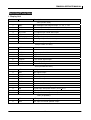
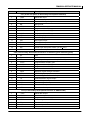
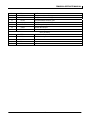
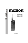
CONTENTS
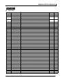
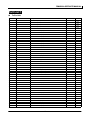
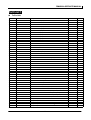
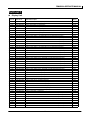
General…………………………………………………………………………………………..1
Radio Overview………………………………………………………………………….………2
Software Specification…………………………………………………………………………5
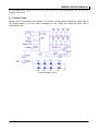
Circuit Description………………………………………………..…………………………..79
Semiconductor Data………………………………………………………………………….84
Component Description…………………………………………..…………………………91
Part List 1…………………………………………………………………………….…………92
Exploded View…………………………………………………………………..……………117
Part List 2…………………………………………………………………………..………….118
Disassembly and Reassembly for Repair………………………………………………..120
Remote Kit Installation (Optional)…………………………………………………….…..123
Packing……………………………………………………………...…………………………125
Adjustment……………………………………………………………………...…………….126
Adjustment Description……………………………………………………………….……133
Terminal Function……………………………………………………………………………139
Display Unit…………………………………………………………………………………...145
Tx-Rx Unit……………………………………………………………………………………..149
VCO…………………………………………………………………………………………….153
Schematic Diagram………………………………………………………………………….157
Block Diagram…………………………………………………………………………….…162
Specifications…………………………………………………………….…………………163
RMU800A SERVICE MANUAL
General
Manual Scope
This manual is intended for use by experienced technicians familiar with similar types of communication
equipment. It contains all service information required for the equipment and is current as of the
publication date.
Precautions
Safety Standards
●
●
●
●
●
●
●
●
Operation Safety Guidelines
●
●
DO NOT operate your radio when someone is either touching or standing within 2 or 3 feet
from the antenna, to avoid the possibility of radio frequency burns or related physical injury.
DO NOT operate the radio near electrical blasting caps or in an explosive atmosphere.
Switch OFF the radio while refueling or parking at gas station.
Turn off your radio in any place where posted notices instruct you to do so.
DO NOT modify the radio for any reason.
DO NOT expose the radio to direct sunlight over a long time, nor place it close to heating
source.
DO NOT place the radio in excessively dusty, humid areas, nor on unstable surfaces.
Refer the service to qualified technicians only.
For vehicles equipped with electronic anti-skid braking systems, electronic ignition systems or
electronic fuel injection systems, interferences may occur during the radio transmission. If the
foregoing electronic equipments are installed on your vehicle, please contact your dealer for
further assistance to make sure that the radio transmission will not interfere with these
equipments.
For radio installation in vehicles fueled by LP gas with LP gas container within interior of the
vehicles, the following precautions are recommended for personal safety.
(1) Any space containing radio equipment shall be isolated by a seal from the space in
which the LP gas container and its fittings are located.
(2) Remote (outside) fitting connections shall be used.
(3) Good ventilation is required for the container space.
Installation Safety Guidelines
●
●
Do not mount the mobile radio overhead or on a sidewall unless you take special precautions.
If someone were to remove the radio and fail to replace it properly, road shock could bump
the radio loose, and the falling radio could, in some circumstances, cause serious injury to
the driver or a passenger. In a crash, even when properly installed, the radio could break
loose and become a dangerous projectile.
- 1 -
RMU800A SERVICE MANUAL
Radio Overview
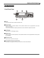
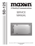
Front Panel View
① Power
Press the power button to switch the radio on/off.
② Selector Knob
Volume Up/Down, Channel Up/Down, Zone Up/Down features can be programmed to this knob
(Set by your dealer).
Turn the knob clockwise to adjust upwards and counter-clockwise to adjust downwards.
③ LCD Display
Please refer to “LCD Display” section.
④ Up/Down Key
Volume Up/Down, Channel Up/Down, Zone Up/Down features can be programmed to the keys (Set
by your dealer).
⑤ Microphone Jack
Insert a 6-pin connector into the jack.
⑥ Programmable Function Key (PF1-PF6)
Your dealer can program these keys as shortcuts to various radio features.
- 2 -
RMU800A SERVICE MANUAL
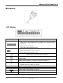
Microphone
LCD Display
Indicator
Description
1. Display zone / channel number.
2. Display zone / channel label (set by your dealer, up to 12 alphanumeric
characters).
3. Display channel Frequency
4. Display the preprogrammed function
1. Display zone / channel number.
2. Display transmit power level (H, M or L).
3. Display the preprogrammed function.
Appears when the selected channel is busy.
Appears when [MONI] key is pressed to disable CTCSS, CDCSS, DTMF or
2-Tone/5-Tone.
Appears when [MONI] key is pressed to switch the speaker on.
A
1. Indicate second development feature.
2. Appears when the auxiliary port is open.
SCAN
Appears while scanning.
CALL
Appears when transmitting selective call.
Appears when a new message is received.
Appears when the selected zone is in the scan list.
Appears when the selected channel is in the scan list.
- 3 -
RMU800A SERVICE MANUAL
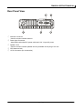
Rear Panel View
① Antenna Connector
Used to connect external antenna.
② Power input Connector
Adopt Relm-authorized DC power cable and 13.6 V input AC power.
③ Speaker Jack
Used to connect external speaker and only available for the plug of 3.5 mm.
④ GPS Antenna Jack
⑤ 15 Pin Connector (for accessories)
- 4 -
RMU800A SERVICE MANUAL
Software Specification
Radio Modes
1.
Frame of Radio Modes
Conventional Mode
User Mode
User Set Mode
Firmware Download
PC Mode
Clone Mode
Wired Clone Mode
Wireless Clone Mode
Dealer Mode
Channel Set Mode
Zone Information Mode
Function Set Mode
Scan Information Mode
DTMF Set Mode
2-Tone Set Mode
5-Tone Set Mode
Embedded Message
Emergency Set Mode
Stun Set Mode
Mode Information Mode
Test & Adjust Mode
Model Set Mode
- 5 -
RMU800A SERVICE MANUAL
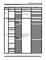
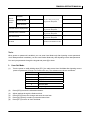
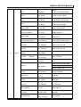
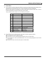
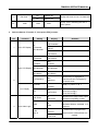
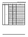
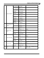
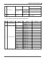
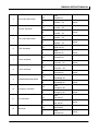
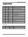
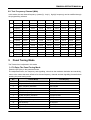
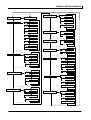
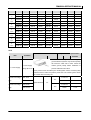
2.
Keypad Entry for Mode Startup
MODE
Main Menu
Conventional
Mode
Display/Sub
Operation
Menu
-------------------------
Remarks
Turn on the power to enter
Conventional Mode
Function Set
MODE
Refer to Appendix 1 “Character
PowerOn Text
USER
User Set Mode
PWR Password
Ust Code
While holding down [PF1]
key, turn on the power
Hook & Moni
Zone Information
Mode
Power on password set
Programmable Function Key
Key Assign
Channel Set Mode
Input”
Channel Set
New zone & ch, edit ch
Only existing Zone can be
Zone Inform
edited
Function 1
Function 2
Function Set
Tone Volume
Alert Tone
Aux Inform
Data Password
Scan Information
Scan Set
Zone Scan List
DTMF Encode
DTMF Set Mode
DTMF Decode
Auto Dial List
PTT ID
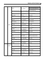
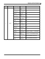
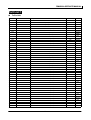
DEALER
2 Tone Set Mode
MODE
2Tone Encode
Turn on the power while
2Tone Decode
holding down [PF6] key to
2Tone Option
enter Dealer Mode, select
Parameter
one of Menu items.
Encode Teleg
5 Tone Set Mode
Encode Frame
Encode Option
Decode Teleg
Decode Option
Embedded
Message
Emergency set
Stun Set
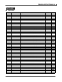
Mode Information
Embedded Msg1
32 bytes
Embedded Msg2
32 bytes
Embedded Msg3
32 bytes
Embedded Msg4
32 bytes
Msg Password
Protect Msg
Emergency Set
Stun Inform
Stun Password
Password Authentication
Mode Select
Password Authentication
Mode Password
- 6 -
RMU800A SERVICE MANUAL
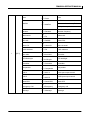
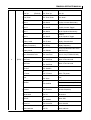
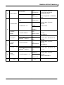
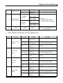
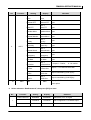
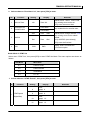
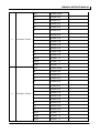
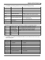
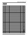
Test Mode
TEST &
ADJUST
ADJUST MODE
MODE
Model Set Mode
Firmware Version Display Mode
Firmware Down Load Mode
Wire Clone Mode
-----------------------------------------------------
While holding down [PF2]
-
key, turn on the power
-----------------------------------------------------
While holding down [PF3]
-
key, turn on the power
---------------------------
While holding down [PF4]
-
key, turn on the power
---------------------------
While holding down [PF5]
-
key, turn on the power
--------------------------Receive commands from PC
PC Mode
-
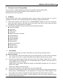
Note:
When power-on password is enabled, you can enter User Mode only after inputting correct password.
And if data password is enabled, you can enter Dealer Mode only after inputting correct data password.
You can input password through the keypad and press [#] to clear.
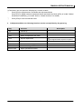
3.
(1)
User Set Mode
Turn the power on while holding down [PF1], the radio enters User Set Mode after inputting correct
power-on password (if Power-On Password is set). The submenus are shown as follows:
Menu Item
Sub Menu
(2)
(3)
(4)
(5)
(6)
1
Function Set
2
PowerOnText
3
PWR Password
4
UST Code
5
Hook & Moni
6
Key Assign
Press [PF6] to enter the selected submenu.
Adjust settings through the Selector Knob.
Press [PF6] to save the change and enter the next item.
Press [Up]/ [Down] to select your desired menu item.
Press [PF1] to return to User Set Mode.
- 7 -
RMU800A SERVICE MANUAL
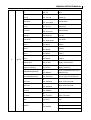
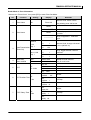
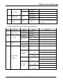
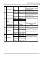
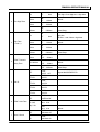
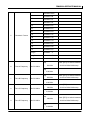
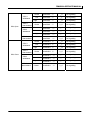
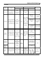
Function Set
Select submenu “Function Set”, then press [PF6] to enter Function Set Mode.
No.
Function Name
1
Home Channel
Settings
Display
Home Off
Home Off
Home 1 On
Home 1 On
Home 2 On
Home 2 On
Home Both On
Home Both On
Zone Home
Channel
2
Home Channel 1
3
Home Channel 2
Remarks
Home Zone
Zone
1
Channel
Selector Knob: change a zone/ch
Home1
Zone
1
1
Channel
[PF5]: toggle between zone and ch
Selector Knob: change a zone/ch
Home2
1
[PF5]: toggle between zone and ch
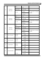
Power On Text
Select submenu “PowerOnText”, press [PF6], the power-on text is displayed. Press [PF1] to edit the
power-on text.
No.
Function Name
Settings
Power On Text
None
1
Display
Remarks
------------------- Refer to Appendix 1 “Character
Input”
Relm MOBILE
Max.12 characters
Power on text
Power On Password
Select submenu “PWR Password”, press [PF6], the power-on password is displayed. Press [PF1] to edit
the power-on password.
No.
1
Function Name
Power On Password
Settings
Display
None
------------
Power on password
88888888
- 8 -
Remarks
Refer to Appendix 1 “Character Input”
Max. 8 digits
RMU800A SERVICE MANUAL
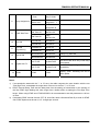
UST Code
Select submenu “UST Code”, press [PF6] to enter UST Code Mode.
No.
Function Name
1
UST Code No.
Settings
Display
1-32
UST
Remarks
1
UST 32
2
UST Code Name
ASCII CODE
Name
--------
No input
R
OFF
Off
CTCSS
(EIA standard)
R
CTCSS
67.0
67.0-254.1Hz
R
CTCSS 254.1
CTCSS
R
CTCSS
(0.1Hz
step)
67.0-254.1Hz
67.0*
R
CTCSS 254.1*
R
CDCSS (standard) CDCSS 023N
3
RX Signalling
023-754
CDCSS (1 step)
000-777
R
CDCSS 754N
R
CDCSS 000N*
R
CDCSS 777N*
R
CDCSS (standard) CDCSS 023I
023-754 reverse
CDCSS (1step)
000-777 reverse
R
CDCSS 754I
R
CDCSS 000I*
R
CDCSS 777I*
- 9 -
[PF5]:
OFF/CTCSS/CDCSS
[PF4]: standard/step mode
[PF3]: CDCSS/ reverse CDCSS
RMU800A SERVICE MANUAL
T
OFF
Off
CTCSS
(EIA standard)
67.0-254.1Hz
CTCSS
(0.1Hz step)
67.0-254.1Hz
4
TX Signalling
T
CTCSS
67.0
R
CTCSS 254.1
T
CTCSS
67.0*
T
CTCSS 254.1*
T
CDCSS (standard) CDCSS 023N
023-754
T
[PF5]: Off/CTCSS/CDCSS
CDCSS 754N
[PF4]: standard/step mode
T
CDCSS 000N*
[PF3]: CDCSS/ reverse CDCSS
CDCSS (1step)
000-777
T
CDCSS 777N*
T
CDCSS (standard) CDCSS 023I
023-754 reverse
T
CDCSS 754I
CDCSS (1step)
000-777 reverse
5
END
END
T
CDCSS 000I*
T
CDCSS 777I*
END
Display “END” indicating the end
of menu options
Hook & Moni
Select submenu “Hook & Moni”, press [PF6] to enter Hook & Moni Mode.
NO.
1
Function
Setting
Display
Hook
HandMic Hook
Selected
when
microphone is used
Moni
TableMicMoni
Selected
when
microphone is used
Hook & Moni
- 10 -
Remarks
hand
desktop
RMU800A SERVICE MANUAL
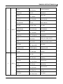
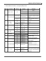
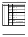
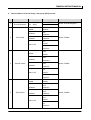
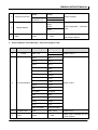
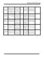
Key Assignment
Select submenu “Key Assign”, press [PF6] to program the programmable function key PF1-PF6.
No.
1
Key
[PF1]
Settings
Display
Remarks
Off
1
PF1 Off
None
VOL Up
2
PF1 VOL Up
Volume up
VOL Down
3
PF1 VOL Down
Volume down
CH Up
4
PF1 CH Up
Channel up
CH Down
5
PF1 CH Down
Channel down
Zone Up
6
PF1 Zone Up
Zone up
Zone Down
7
PF1 Zone Down
Zone down
MONI A
8
PF1 MoniA
MONI A:
Monitor Unmute-Momentary
MONI B
9
PF1 MoniB
MONI B:
Monitor Unmute-Toggle
10
PF1 MoniC
MONI C:
Carrier Squelch-Momentary
MONI D
11
PF1 MoniD
MONI D:
Carrier Squelch-Toggle
Display Label
12
PF1 DLabel
Display channel label
Display Frequency
13
PF1 DFreq
Display frequency
Display Mode
14
PF1 DMode
Ch No./ch label/zone No./zone
label/RX Freq.
User Selectable Tone
15
PF1 UserTone
Tone 01-32(CTCSS/CDCSS)
Sel 2Tone
16
PF1 Sel2Tone
Select 2-Tone encode
Sel 5Tone
17
PF1 Sel5Tone
Select 5-Tone encode
Sel HDC
18
PFI SelHDC
Tx Power
19
PF1 TxPower
MONI C
[Default]
- 11 -
Switch TX power
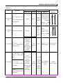
RMU800A SERVICE MANUAL
Scan
20
PF1 Scan
Scan
Add/Del in non-scan mode
Add/Del
21
PF1 Add/Del
Nuisance channel temp.Del
Priority ch temp. del
1
[PF1]
Reverse
22
PF1 Reverse
Reverse frequency
Talk Around
23
PF1 TA
Talkaround
SEL SQL
24
PF1 SelSQL
Select SQL
Home CH
25
PF1 HomeCH
Home channel
Public Address
26
PF1 PA
Public address
Horn Alert
27
PF1HornAlert
Horn alert
LCD BackLight
28
PF1LCDLight
LCD backlight
Scrambler
29
PF1 Scramble
Scrambler
Compander
30
PF1 Compande
Compander
AUX A
31
PF1 AUX A
AUXA port output control
AUX B
32
PF1 AUX B
AUXB port output control
Send GPS
33
PF1 Send GPS
Send GPS
Emergency Call
34
PF1Emergency
Emergency call
Message
35
PF1 Message
Message
- 12 -
RMU800A SERVICE MANUAL
2
[PF2]
Off
1
PF2 Off
None
VOL Up
2
PF2 VOL Up
Volume up
VOL Down
3
PF2 VOL Down
Volume down
CH Up
4
PF2 CH Up
Channel up
CH Down
5
PF2 CH Down
Channel down
Zone Up
6
PF2 Zone Up
Zone up
Zone Down
7
PF2 Zone Down
Zone down
Moni A
8
PF2 MoniA
MONI A
Moni B
9
PF2 MoniB
MONI B
Moni C
10
PF2 MoniC
MONI C
Moni D
11
PF2 MoniD
MONI D
DisplayLabel
12
PF2 DLabel
Display channel label
Display Frequency
13
PF2 DFreq
Display frequency
DisplayMode [Default]
14
PF2 DMode
Ch No./ch label/zone No./zone
label/RX Freq.
User Selectable Tone
15
PF2 UserTone
Tone 01-32(CTCSS/CDCSS)
Sel 2Tone
16
PF2 Sel2Tone
Select 2-Tone encode
Sel 5Tone
17
PF2 Sel5Tone
Select 5-Tone encode
Sel HDC
18
PF2 SelHDC
Tx Power
19
PF2 TxPower
Switch TX power
Scan
20
PF2 Scan
Scan
Add/Del as not in scan status
Add/Del
21
PF2 Add/Del
Nuisance channel temp.Del
Priority ch temp. del
- 13 -
RMU800A SERVICE MANUAL
2
3
[PF2]
[PF3]
Reverse
22
PF2 Reverse
Reverse frequency
Talk Around
23
PF2 TA
Talkaround
Sel SQL
24
PF2 SelSQL
Select SQL
Home CH
25
PF2 HomeCH
Home channel
Public Address
26
PF2 PA
Public address
Horn Alert
27
PF2Horn Alert
Horn alert
LCD BackLight
28
PF2 LCD Light
LCD backlight
Scramble
29
PF2 Scramble
Scrambler
Compander
30
PF2 Compande
Compander
AUX A
31
PF2 AUX A
AUXA port output control
AUX B
32
PF2 AUX B
AUXB port output control
Send GPS
33
PF2 Send GPS
Send GPS
Emergency Call
34
PF2Emergency
Emergency call
Message
35
PF2 Message
Message
Off
1
PF3 Off
None
VOL Up
2
PF3 VOL Up
Volume up
VOL Down
3
PF3 VOL Down
Volume down
CH Up
4
PF3 CH Up
Channel up
CH Down
5
PF3 CH Down
Channel down
Zone Up
6
PF3 Zone Up
Zone up
Zone Down
7
PF3 Zone Down
Zone down
- 14 -
RMU800A SERVICE MANUAL
3
[PF3]
Moni A
8
PF3 MoniA
MONI A:
Monitor Unmute-Momentary
Moni B
9
PF3 MoniB
MONI B:
Monitor Unmute-Toggle
Moni C
10
PF3 MoniC
MONI C:
Carrier Squelch-Momentary
Moni D
11
PF3 MoniD
MONI D:
Carrier Squelch-Toggle
Display Label
12
PF3 DLabel
Display channel label
Display Frequency
13
PF3 DFreq
Display frequency
Display Mode
14
PF3 DMode
Ch No./ch label/zone No./zone
label/RX Freq.
User Selectable Tone
15
PF3 UserTone
Tone 01-32(CTCSS/CDCSS)
Sel 2Tone
16
PF3 Sel2Tone
Select 2-Tone encode
Sel 5Tone
17
PF3 Sel5Tone
Select 5-Tone encode
Sel HDC
18
PF3 SelHDC
Tx Power
[Default]
Scan
Add/Del
19
PF3 TxPower
Switch TX power
20
PF3 Scan
Scan
21
PF3 Add/Del
Add/Del as not in scan status
Nuisance channel temp.Del
Priority ch temp. del
Reverse
22
PF3 Reverse
Reverse frequency
Talk Around
23
PF3 TA
Talkaround
Sel SQL
24
PF3 SelSQL
Select SQL
Home CH
25
PF3 HomeCH
Home channel
Public Address
26
PF3 PA
Public address
Horn Alert
27
PF3Horn Alert
Horn alert
LCD BackLight
28
PF3 LCD Light
LCD backlight
- 15 -
RMU800A SERVICE MANUAL
3
4
[PF3]
[PF4]
Scramble
29
PF3 Scramble
Scrambler
Compander
30
PF3 Compande
Compander
AUX A
31
PF3 AUX A
AUXA port output control
AUX B
33
PF3 AUX B
AUXB port output control
Send GPS
33
PF3 Send GPS
Send GPS
Emergency Call
34
PF3Emergency
Emergency call
Message
35
PF3 Message
Message
Off
1
PF4 Off
None
VOL Up
2
PF4 VOL Up
Volume up
VOL Down
3
PF4 VOL Down
Volume down
CH Up
4
PF4 CH Up
Channel up
CH Down
5
PF4 CH Down
Channel down
Zone Up
6
PF4 Zone Up
Zone up
Zone Down
7
PF4 Zone Down
Zone down
Moni A
8
PF4 MoniA
MONI A:
Monitor Unmute-Momentary
Moni B
9
PF4 MoniB
MONI B:
Monitor Unmute-Toggle
Moni C
10
PF4 MoniC
MONI C:
Carrier Squelch-Momentary
Moni D
11
PF4 MoniD
MONI D:
Carrier Squelch-Toggle
DispayLabel
12
PF4 DLabel
Display channel label
Display Frequency
13
PF4 DFreq
Display frequency
- 16 -
RMU800A SERVICE MANUAL
Display Mode
14
PF4 DMode
Ch No./ch label/zone No./zone
label/RX Freq.
User Selectable Tone
15
PF4 UserTone
Tone 01-32(CTCSS/CDCSS)
Sel 2Tone
16
PF4 Sel2Tone
Select 2-Tone encode
Sel 5Tone
17
PF4 Sel5Tone
Select 5-Tone encode
Sel HDC
18
PF4 SelHDC
Tx Power
19
PF4 TxPower
Switch TX power
20
PF4 Scan
Scan
Scan
[Default]
Add/Del
4
21
PF4 Add/Del
Add/Del as not in scan status
Nuisance channel temp.Del
Priority ch temp. del
Reverse
22
PF4 Reverse
Reverse frequency
Talk Around
23
PF4 TA
Talkaround
Sel SQL
24
PF4 SelSQL
Select SQL
Home CH
25
PF4 HomeCH
Home channel
Public Address
26
PF4 PA
Public address
Horn Alert
27
PF4Horn Alert
Horn alert
LCD BackLight
28
PF4 LCD Light
LCD backlight
Scramble
29
PF4 Scramble
Scrambler
Compander
30
PF4 Compande
Compander
AUX A
31
PF4 AUX A
AUXA port output control
AUX B
32
PF4 AUX B
AUXB port output control
Send GPS
33
PF4 Send GPS
Send GPS
Emergency Call
34
PF4Emergency
Emergency call
[PF4]
- 17 -
RMU800A SERVICE MANUAL
5
[PF5]
Message
35
PF4 Message
Message
Off
1
PF5 Off
None
VOL Up
2
PF5 VOL Up
Volume up
VOL Down
3
PF5 VOL Down
Volume down
CH Up
4
PF5 CH Up
Channel up
CH Down
5
PF5 CH Down
Channel down
Zone Up
6
PF5 Zone Up
Zone up
Zone Down
7
PF5 Zone Down
Zone down
Moni A
8
PF5 MoniA
MONI A:
Monitor Unmute-Momentary
Moni B
9
PF5 MoniB
MONI B:
Monitor Unmute-Toggle
Moni C
10
PF5 MoniC
MONI C:
Carrier Squelch-Momentary
Moni D
11
PF5 MoniD
MONI D:
Carrier Squelch-Toggle
Display Label
12
PF5 DLabel
Display channel label
Display Frequency
13
PF5 DFreq
Display frequency
Display Mode
14
PF5 DMode
Ch No./ch label/zone No./zone
label/RX Freq.
User Selectable Tone
15
PF5 UserTone
Tone 01-32(CTCSS/CDCSS)
Sel 2Tone
16
PF5 Sel2Tone
Select 2-Tone encode
Sel 5Tone
17
PF5 Sel5Tone
Select 5-Tone encode
Sel HDC
18
PF5 SelHDC
Tx Power
19
PF5 TxPower
Switch TX power
Scan
20
PF5 Scan
Scan
[Default]
- 18 -
RMU800A SERVICE MANUAL
Add/Del as not in scan status
Add/Del
21
PF5 Add/Del
Nuisance channel temp.Del
Priority ch temp. del
5
[PF5]
Reverse
22
PF5 Reverse
Reverse frequency
Talk Around
23
PF5 TA
Talkaround
Sel SQL
24
PF5 SelSQL
Select SQL
Home CH
25
PF5 HomeCH
Home channel
Public Address
26
PF5 PA
Public address
Horn Alert
27
PF5Horn Alert
Horn alert
LCD BackLight
28
PF5 LCD Light
LCD backlight
Scramble
29
PF5 Scramble
Scrambler
Compander
30
PF5 Compande
Compander
AUX A
31
PF5 AUX A
AUXA port output control
AUX B
32
PF5 AUX B
AUXB port output control
Send GPS
33
PF5 Send GPS
Send GPS
Emergency Call
34
PF5Emergency
Emergency call
Message
35
PF5 Message
Message
Off
1
PF6 Off
None
VOL Up
2
PF6 VOL Up
Volume up
VOL Down
3
PF6 VOL Down
Volume down
CH Up
4
PF6 CH Up
Channel up
CH Down
5
PF6 CH Down
Channel down
[PF6]
6
- 19 -
RMU800A SERVICE MANUAL
6
PF6 Zone Up
Zone up
Zone Down
7
PF6 Zone Down
Zone down
Moni A
8
PF6 MoniA
MONI A:
Monitor Unmute-Momentary
Moni B
9
PF6 MoniB
MONI B:
Monitor Unmute-Toggle
Moni C
10
PF6 MoniC
MONI C:
Carrier Squelch-Momentary
Moni D
11
PF6 MoniD
MONI D:
Carrier Squelch-Toggle
Display Label
12
PF6 DLabel
Display channel label
Display Frequency
13
PF6 DFreq
Display frequency
Display Mode
14
PF6 DMode
Ch No./ch label/zone No./zone
label/RX Freq.
User Selectable Tone
15
PF6 UserTone
Tone 01-32 (CTCSS/CDCSS)
Sel 2Tone
16
PF6 Sel2Tone
Select 2-Tone encode
Sel 5Tone
17
PF6 Sel5Tone
Select 5-Tone encode
Sel HDC
18
PF6 SelHDC
Tx Power
19
PF6 TxPower
Switch TX power
Scan
20
PF6 Scan
Scan
Zone Up
6
[PF6]
Add/Del
[Default]
21
PF6 Add/Del
Add/Del as not in scan status
Nuisance channel temp.Del
Priority ch temp. del
Reverse
22
PF6 Reverse
Reverse frequency
Talk Around
23
PF6 TA
Talkaround
Sel SQL
24
PF6 SelSQL
Select SQL
Home CH
25
PF6 HomeCH
Home channel
Public Address
26
PF6 PA
Public address
- 20 -
RMU800A SERVICE MANUAL
6
7
8
9
[PF6]
[SELECTOR
KNOB]
[Up/Down]
END
Horn Alert
27
PF6Horn Alert
Horn alert
LCD BackLight
28
PF6 LCD Light
LCD backlight
Scramble
29
PF6 Scramble
Scrambler
Compander
30
PF6 Compande
Compander
AUX A
31
PF6 AUX A
AUXA port output control
AUX B
32
PF6 AUX B
AUXB port output control
Send GPS
33
PF6 Send GPS
Send GPS
Emergency Call
34
PF6Emergency
Emergency call
Message
35
PF6 Message
Message
Volume Knob [Default]
Volume Knob
Volume knob
Channel Knob
Channel Knob
Channel selector knob
Zone Knob
Zone Knob
Zone selector knob
Volume Up/Down
Volume UpDn
Volume knob
Channel Up/Down [Default] Channel UpDn
Channel selector knob
Zone Up/Down
Zone selector knob
Zone UpDn
END
END
Display “END” indicating the end
of menu option
Note: In User Set Mode, turn the power off and back on to enter the Conventional Mode.
4.
Firmware Download Mode
The built-in FLASHROM enables user to add new functions simply by upgrading.
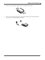
(1)
Turn on the power while holding down [PF4] simultaneously to enter Firmware Download Mode,
“PC Program” appears on the LCD.
(2)
Run the programming software.
(3)
Connect the radio with a PC by programming cable.
(4)
Select the corresponding COM port, then click “Download”.
(5)
When data is successfully written into the radio, click “OK” to exit.
(6)
Repeat step 1-5 to program another radio.
Note: The radio can’t enter the Firmware Download Mode if it is prohibited by your dealer.
It can be set ON only after being programmed through the programming software or by your dealer.
- 21 -
RMU800A SERVICE MANUAL
5.
Firmware Version Display Mode
Turn the power on while holding down [PF3] to enter Firmware Version Display Mode.
Firmware version and Firmware checksum will be displayed on the LCD.
Release [PF3] to enter User Mode.
6.
PC Mode
Connect the radio with a PC by programming cable. If data is written to the radio from PC, it can be
programmed into the FLASH. Data programming is accessible by programming software.
(1) When data is written to the radio from PC, “PROGRAMMING” appears on the LCD. LED glows
green when data is written to the radio and red when data is read from the radio. Radio will restart
automatically when programming is completed.
(2) The following parameters can be set through the programming software.
● Frequency stability
● High power
● Middle power
● Low power
● Maximum frequency deviation
● CDCSS balance
● CTCSS deviation
● CDCSS deviation
● DTMF deviation
● MSK deviation
● Single Tone deviation
● RX sensitivity
● Squelch Level 9
● Squelch Level 3
7.
Clone Mode
Data can be transferred from radio to radio either by wired cloning or wireless cloning.
Wired Clone Mode
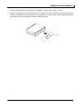
(1)
Turn on the source radio while holding down [PF5] simultaneously, the radio enters Clone Mode
with “CLONE” on the LCD, or enters User Mode if Clone Mode is set OFF by your dealer.
(2)
Press [PF2] to toggle between Dealer Clone and Factory Clone Mode. “Dealer Clone” or “Factory
Clone” appears on the display when the corresponding mode is selected. The radio returns to
original display mode in 5 seconds.
Unlike Factory Clone Mode, adjustment settings and embedded messages are not covered in
Dealer Clone Mode.
Dealer Clone Mode is the default mode.
(3)
Connect the two radios by clone cable, then turn on the target radio.
(4)
Press [PF6] to start cloning, the LED of source radio glows red and that of target radio glows green
during cloning. “PROGRAMMING” is also displayed on the target radio. “END” appears on the
source radio when cloning is completed and the target radio reset when all data is received.
(5)
Press [PF6] to return to Clone Mode. “CLONE” appears on the source radio. Repeat the above
steps to continue wired cloning.
- 22 -
RMU800A SERVICE MANUAL
Note: Only the same models can be cloned together.
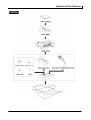
Wireless Clone Mode
(1)
Turn on the source radio while holding down [PF5] simultaneously, the radio enters Clone Mode with
“CLONE” on the LCD, or enters User Mode if Clone Mode is set OFF by your dealer.
(2) Press [PF1], the radio enters Wireless Clone Mode with “WIRELESS” on the LCD. The initial
frequency that matches the destination is displayed in 2 seconds. Turn the Selector Knob to choose
desired frequency. Press [PF1] again to return to Clone Mode.
(3) Press [PF2] to toggle between Dealer Clone and Factory Clone Mode. “Dealer Clone” or “Factory
Clone” appears on the display when the corresponding mode is selected. The radio returns to
original display mode in 5 seconds.
Unlike Factory Clone Mode, adjustment settings and embedded messages are not covered in
Dealer Clone Mode.
Dealer Clone Mode is the default mode.
(4) Repeat step1-2 to operate the target radio, the frequency is set the same as that of source radio.
(5) Press [PF6] to start wireless cloning. The LED of source radio glows red and that of target radio
glows green during cloning. “CLONE 00%” is displayed on both source and target radios. “BUSY”
mark also appears on the target radio. The leftmost 2 digits (00) on the LCD show the data transfer
rate and count upwards in increments of 1 as data transmission/reception proceeds.
(6)
(6) When data transmission is completed, “END” appears on the source radio and red LED goes
out. Press [PF1], the source radio displays the frequency, repeat the above steps to continue
wireless cloning. The target radio reset when all data is received.
Note: Clone Mode can be enabled/disabled by your dealer. Wired cloning is accessible only when Clone
Mode is enabled. Refer to “Clone Mode” in “Mode Information” of “Dealer Mode”.
- 23 -
RMU800A SERVICE MANUAL
8.
Dealer Mode
(1) Turn the power on while holding down [PF6], the radio enters Dealer Mode after inputting correct
data password (if Data Password is set). The first activated mode option is displayed.
When all mode options are prohibited, the radio enters Mode Information Mode after a correct
mode-info password (if mode-info Password is set) is entered.
Turn the Selector Knob to select one of the following mode options:
No.
(2)
Dealer Mode Option
LCD Display
1
Channel Set Mode
Channel Set
2
Zone Information Mode
Zone Inform
3
Function Set Mode
Function Set
4
Scan Information Mode
Scan Inform
5
DTMF Set Mode
DTMF Set
6
2-Tone Set Mode
2-Tone Set
7
5-Tone Set Mode
5-Tone Set
8
Embedded Message
EmbeddedMsg
9
Emergency Set Mode
EmergencySet
10
Stun Set Mode
Stun Inform
11
Mode Information
Mode Inform
Press [PF6] to enter the selected dealer mode option, and then operate as follows:
● Turn the Selector Knob to adjust the setting.
● Press [PF6] to save the selected settings and goes to the next mode option.
● Press [Up]/[Down] to select upwards/downwards. The current setting displayed on the LCD will
not be saved.
● Press [PF1] to return to the first mode option or Dealer Mode.
- 24 -
RMU800A SERVICE MANUAL
Dealer Mode 1: Channel Set
Select menu “Channel Set”, then press [PF6] to enter Channel Set Mode.
No.
Function Name
Settings
Channel
Step 1
1
Display
1
CH
1-512
Zone
Channel
Zone 1-256
Step 1
Remarks
1
1
CH
512
1
CH
1
256
CH
1
Selector Knob: change a
channel or zone (default: ch)
[PF5]: toggle between channel
and zone
250 0
R 100.00000
2
RX Frequency
2.5K/5.0K/6.25K/1M
100.0000-550.0000MHz
RX Signalling
625 0
R 400.00000
1M
R 550.00000
Blank
---------------
OFF
R
Off
CTCSS (EIA standard)
67.0-254.1Hz
3
500 0
R 400.00000
CTCSS (0.1Hz
67.0-254.1Hz
step)
CDCSS (standard)
023-754
CDCSS (1 step)
000-777
R
CTCSS
Selector Knob: change at step
frequency
[PF4]: 2.5K/5.0K/6.25K/1M step
Step 2.5K: only for RMU800A
VHF(<200MHz)
[PF5]: On/Blank
67.0
R
CTCSS 254.1
R
CTCSS
67.0*
R
CTCSS 254.1*
R
CDCSS 023N
R
CDCSS 754N
R
CDCSS 000N*
R
CDCSS 777N*
- 25 -
[PF5]: Off/CTCSS/CDCSS
[PF4]: standard/step mode
[PF3]: CDCSS /reverse CDCSS
RMU800A SERVICE MANUAL
R
CDCSS 023I
CDCSS (standard)
023-754 reverse
3
R
CDCSS 754I
RX Signalling
R
CDCSS 000I*
CDCSS (1 step)
000-777 reverse
R
CDCSS 777I*
250 0
T 100.00000
4
TX Frequency
2.5K/5.0K/6.25K/1M
100.0000-550.0000MHz
500 0
T 400.00000
625 0
T 400.00000
Selector Knob: change at step
frequency
[PF4]: 2.5K/5.0K/6.25K/1M step
Step 2.5K: only for RMU800A
VHF(<200MHz)
1M
T 550.00000
Blank
--------------T
OFF
Off
CTCSS (EIA standard)
67.0-254.1Hz
CTCSS (0.1Hz
67.0-254.1Hz
5
TX Signalling
step)
CDCSS (standard)
023-754
CDCSS (1 step)
000-777
CDCSS (standard)
023-754 reverse
CDCSS (1 step)
000-777 reverse
[PF5]: On/Blank
T
CTCSS
67.0
T
CTCSS 254.1
T
CTCSS
67.0*
T
CTCSS 254.1*
T
CDCSS 023N
T
CDCSS 754N
T
CDCSS 000N*
T
CDCSS 777N*
T
CDCSS 023I
T
CDCSS 754I
T
CDCSS 000I*
T
CDCSS 777I*
- 26 -
[PF5]: Off/CTCSS/CDCSS
[PF4]: standard/step mode
[PF3]: CDCSS / reverse CDCSS
RMU800A SERVICE MANUAL
6
Optional
Signalling
Off
Option Off
DTMF
DTMF
2-Tone
2 Tone
5-Tone
5 Tone
HDC2400TM
HDC2400
HDC1200
HDC1200
BCL
Off
Default
Default
Off
BCL
7
BCL (Busy
CTCSS/CDCSS
Channel Lockout)
CTCSS/CDCSS
BCL
Opt Signalling
Opt Signal
BCL
8
9
Clock Shift
TX Power
10
Wideband /
Narrowband
11
Scan ADD/DEL
12 Compander
13 Scrambler
14 PTT ID
Carrier Only
Carrier Only
Off
Shift Off
On
Shift On
High
TXPower HI
Middle
TXPower MI
Low
TXPower LO
Default
Wide
Wide Band
Default
Narrow
Narrow Band
Delete
Scan Del
Add
Scan Add
Off
Compand Off
On
Compand On
Off
Scramble Off
On
Scramble On
Off
PTTID Off
PTT ID 1
PTT ID 1
PTT ID 2
PTT ID 2
PTT ID 3
PTT ID 3
PTT ID 4
PTT ID 4
5-Tone
5Tone
- 27 -
Default
Default
Default
RMU800A SERVICE MANUAL
PHILLPOTTS
Name
PHILLPOTTS
-----------------
Name
-----------------
None
2T
Decode None
15 Channel Name
2T
Decode 1
2-Tone Decode
2-ToneDecode 1-8
5-Tone Rx
Address
HDC2400
5-Tone Rx Address
5TRx
Address 12345
None
None
HDC2400TM Call 1-8
List 1
List 8
5-Tone Tx Address
5TTx
Address23456
TM
5-Tone Tx
Address
None
HDC2400TM Call
2
HDC2400TM Call 1-8
5-Tone
18
Parameter
19
Appears when 2-Tone is
selected
Default: None
2T
Decode 8
16
17
12 characters maximum
Current input position is
indicated by cursor
Refer to Appendix 1 “Character
Input”
END
None
List 1
List 8
5T
Parameter 1
5-Tone Parameter 1-16
5T
Parameter 16
END
END
- 28 -
Appears when 5-Tone is
selected
User-defined
Default: None
Appears when HDC2400TM is
selected
Appears when 5-Tone is
selected
User-defined
Default: None
Appears when HDC2400TM is
selected
Appears when 5-Tone is
selected
Default: Parameter 1
RMU800A SERVICE MANUAL
Dealer Mode 2: Zone Information
Select menu “Zone Inform”, then press [PF6] to enter Zone Set Mode.
No.
1
Function
Zone Select
Display
Setting
100
Zone 100
Remarks
Selector Knob: select a zone
Only existing zone can be set.
Name
PHILLPOTTS
2
Zone Name
Name
-----------------
3
Data Transmission
(Zone-CH)
Channel
1-512
Step 1
Zone 1-256
Step 1
4
Multi-Scan
Scan Add/Del
ADD
DEL
1
CH
1
CH
1
512
1
CH
1
256
CH
1
12 characters maximum
Current input position is indicated
by cursor
Refer to Appendix 1 ‘Character
Input”
Selector Knob: change a channel
or zone (default ch)
[PF5]: toggle between channel
and zone
MultiLst Add
MultiLst Del
Add/del to multi-scan list
Only for multi-scan
TOT Off
5
TOT
Off
15~1200s
TOT
15
15s/1Step
TOT 180
Default
TOT 1200
6
TOT PreAlert Time
Off
1-10s
TOT
PreAlert
Off
TOT
PreAlert
1
TOT
PreAlert
10
TOT
Rekey Off
7
TOT Rekey Time
Off
1-60s
1s/1Step
Default
TOT
ReKey
1
TOT
ReKey
60
- 29 -
Default
1s/1Step
RMU800A SERVICE MANUAL
TOT
Reset Off
8
9
10
Off
TOT Reset Time
TOT
Reset
1
TOT
Reset
15
Or
Signal
OR
And
Signal
AND
On
CLR
Transpond On
Off
CLR
TranspondOff
1-15s
Signalling Control
Default
1s/1Step
Default
ClearToTranspond
11
Zone Home
Channel
12
END
1-512
END
Home
Channel 1
Default
Default
Home
Channel 512
Display “END” indicating the end
END
of menu option
Dealer Mode 3: Function Set
Select menu “Function Set”, then press [PF6] to enter Function Set Mode. The menu options are shown
as follows:
Sub Menu
Menu Item
3.1
Function 1
3.2
Function 2
3.3
Tone Volume
3.4
Alert Tone
3.5
Aux Inform
3.6
DataPassword
- 30 -
RMU800A SERVICE MANUAL
1. Select submenu “Function 1”, then press [PF6] to enter.
No.
1
Function
Squelch Level
Setting
0-9
Display
Remarks
SQL 0
Step: 1
SQL 5
Default
SQL 9
Off
HookNoDecode
Not decode ctcss/cdtcc during off
hook status, it works as carrier
squelch
Decode
Off
Hook Decode
Decode ctcss/cdtcc during off
hook status
Off
Off
Hook No HA
Horn alert is not available when
off hook
On
Off
Hook HA
Horn alert is available when off
hook
Off
PTT
RL Tone
Off
On
PTT
RL Tone
On
Off
BusyLED Off
On
BusyLED On
Off
USTBackUpOff
On
USTBackUp On
Off
ScramBak Off
Scrambler setting
On
ScramBak On
BackUp to current channel
Off
CompdBak Off
Compand setting backUp to
On
CompdBak On
current channel
Off
HABackUp Off
On
HABackUp On
The Horn Alert on status is
memorized.
The Horn Alert on status is
cleared when the radio is turned
off.
Off
BCL
Override Off
On
BCL
Override On
Not decode
2
3
4
5
Off Hook Decode
Off Hook
Horn Alert
PTT Release Tone
Busy LED
6
UST BackUp
7
Scrambler BackUp
8
9
10
Compand BackUp
Horn Alert BackUp
BCL Override
- 31 -
UST RX/TX signalling setting
To transmit in Busy Channel
Lockout mode, press [PTT] again
within approx. 500ms after [PTT]
is released
RMU800A SERVICE MANUAL
11
12
2.
Roll Over
END
Off
RollOver Off
On
RollOver On
END
Display rolls over as over 12 characters
Display “END” indicating the end of
menu options
END
Select submenu “Function 2”, then press [PF6] to enter.
No.
1
Function
Setting
Off
Sub LCD Display CH Number
Zone Number
SUB
LCD ChNum
CH Name
Main
Ch Name
Main
Zone Number
Main
Zone Name
CH Frequency
Main
Frequency
RX frequency is displayed in
receive mode and TX frequency
in transmit mode
Tx Power
Icon
Tx Power
Display Tx power: H, M, L
Aux
Icon
AuxFunction
Aux function: D(data),G(GPS)
A(Aux Out A=High),
B(Aux Out B=High)
Until Reset
HA
Until Reset
Continuous low (logic level) output
until Option Signalling is reset.
Pulse
HA
Pulse
The Horn Alert port is activated 1s,
inactivated 500ms, activated 1s in
sequence.
Icon Display
4
SUB
LCD Off
SUB
LCD ChNum
Zone Name
Remarks
SUB
LCD ZoneNum
CH Number
Main LCD Display Zone Number
2
Display
Horn Alert Logic
1-30s
step 1s
HA
1 second
HA
30 seconds
- 32 -
Continuous low (logic level)
output until the selected time has
expired.
RMU800A SERVICE MANUAL
5
Ignition Sense
Off
Ignition Off
On
Ignition On
00-59Min
Step 1Min
6
Ignition Sense
Power off Timer
00-24Hour
Step 1Hour
7
3.
END
IGN
00Hour 00Min
IGN
00Hour 59Min
IGN
00Hour 00Min
Adjust timer:
0Hour, 0Min-24Hour, 00Min
PF5: 1MIN/1HOUR step change
IGN
24Hour 00Min
END
Display “END” indicating the end
of menu option
END
Select submenu “Tone Volume”, then press [PF6] to enter.
No.
1
2
3
4
Function
Power-Up Tone
Volume
Setting
Alert Tone
Volume
Warning Tone
Volume
Remarks
Off
Tone
PowerUp Off
User Current
Tone
PowerUp User
Use Current volume setting
1-127
Tone
PowerUp
Default: 1
Off
Tone
Control Off
User Current
Tone
Control User
Use Current volume setting
1-127
Tone
Control
Default: 2
Off
Tone
AlertOff
User Current
Tone
Alert User
Use Current volume setting
1-127
Tone
Alert
Default: 3
Off
Tone
Warning Off
User Current
Tone
Warning User
Use Current volume setting
1-127
Tone
Warning 4
Default: 4
Control Tone
Volume
Display
1
2
3
- 33 -
RMU800A SERVICE MANUAL
5
6
7
4.
Volume Min
Volume Max
Off
VolumeMinOff
1-64
Step 1
VolumeMin
64-127
Step 1
END
END
1
VolumeMin 64
VolumeMin 64
VolumeMin 127
Display “END” indicating the end of
menu option
END
Select submenu “Alert Tone”, then press [PF6] to enter.
No.
Function
1
Alert Tone No.
Setting
Alert Tone 1-8
Display
Alert Tone 1
Alert Tone 8
2
3
Cycle
Interval
Continuous
Continuous
Cycle 0-255S
Step 1
Cycle
0S
Cycle
255S
0-255ms
Interv
1ms
Step 1ms
Interv
255ms
Off
400-2550Hz
Step 10Hz
4
Tone Frequency
No. 1-14
Step 1
Off
400-2550Hz
Step 10Hz
Freq
No.1
----
Freq
No.1
400Hz
Freq
No.1
2550Hz
Freq
No.14
----
Freq
No.14
400Hz
Freq
No.14
2550Hz
- 34 -
Remarks
RMU800A SERVICE MANUAL
0-2550ms
Step 10ms
5
Tone Duration
No. 1-14
Step 1
0-2550ms
Step 10ms
6
5.
END
END
Dura
No.1
0ms
Dura
No.1
2550ms
Dura
No.14
0ms
Dura
No.14
2550ms
END
Display “END” indicating the end
of menu option
Select submenu “AUX Inform”, then press [PF6] to enter.
No.
Function
Setting
None
1
2
UART0
UART1
Display
UART
0
None
Data
UART
0
Data
None
UART
1
None
GPS
UART
1
GPS
SmarTrunk
UART
1 SmarTrunk
- 35 -
Remarks
RMU800A SERVICE MANUAL
No.
3
Function
AUX1
Setting
Display
Remarks
None
AUX 1
None
External PTT
AUX 1
External PTT
Input
Data PTT
AUX 1
Data PTT
Input
Speaker Mute
AUX 1
Speaker Mute
Input
External Monitor
AUX 1
ExternalMoni
Input
Up Key
AUX 1
Up Key
Input
Down Key
AUX 1
Down Key
Input
External Hook
AUX 1
ExternalHook
Input
Emergency
AUX 1
Emergency
Input
Mic Mute
AUX 1
Mic Mute
Input
RxCarrier
AUX 1
RxCarrierOut
RxTone
AUX 1
RxTone Out
Output, L: CTCSS/CDCSS match
AUX A
AUX 1
AUXA Out
Output controlled by [AUX A] key
AUX B
AUX 1
AUXB Out
Output controlled by [AUX B] key
- 36 -
Output, L: Carrier;
H : No carrier
RMU800A SERVICE MANUAL
No.
4
Function
AUX2
Setting
Display
Remarks
None
AUX 2
None
External PTT
AUX 2
External PTT
Input
Data PTT
AUX 1
Data PTT
Input
Speaker Mute
AUX 2
Speaker Mute
Input
External Monitor
AUX 2
ExternalMoni
Input
Up Key
AUX 2
Up Key
Input
Down Key
AUX 2
Down Key
Input
External Hook
AUX 2
ExternalHook
Input
Emergency
AUX 2
Emergency
Input
Mic Mute
AUX 2
Mic Mute
Input
RxCarrier
AUX 2
RxCarrierOut
RxTone
AUX 2
RxTone Out
Output, L: CTCSS/CDCSS match
AUX A
AUX 2
AUXA Out
Output controlled by [AUX A] key
AUX B
AUX 2
AUXB Out
Output controlled by [AUX B] key
- 37 -
Output, L: Carrier;
H : No carrier
RMU800A SERVICE MANUAL
No.
5
Function
AUX3
Setting
Display
Remarks
None
AUX 3
None
External PTT
AUX 3
External PTT
Input
Data PTT
AUX 1
Data PTT
Input
Speaker Mute
AUX 3
Speaker Mute
Input
External Monitor
AUX 3
ExternalMoni
Input
Up Key
AUX 3
Up Key
Input
Down Key
AUX 3
Down Key
Input
External Hook
AUX 3
ExternalHook
Input
Emergency
AUX 3
Emergency
Input
Mic Mute
AUX 3
Mic Mute
Input
RxCarrier
AUX 3
RxCarrierOut
RxTone
AUX 3
RxTone Out
Output, L: CTCSS/CDCSS match
AUX A
AUX 3
AUXA Out
Output controlled by [AUX A] key
AUX B
AUX 3
AUXB Out
Output controlled by [AUX B] key
- 38 -
Output, L: Carrier;
H : No carrier
RMU800A SERVICE MANUAL
No.
6
Function
AUX4
Setting
Display
Remarks
None
AUX 4
None
External PTT
AUX 4
External PTT
Input
Data PTT
AUX 1
Data PTT
Input
Speaker Mute
AUX 4
Speaker Mute
Input
External Monitor
AUX 4
ExternalMoni
Input
Up Key
AUX 4
Up Key
Input
Down Key
AUX 4
Down Key
Input
External Hook
AUX 4
ExternalHook
Input
Emergency
AUX 4
Emergency
Input
Mic Mute
AUX 4
Mic Mute
Input
RxCarrier
AUX 4
RxCarrierOut
RxTone
AUX 4
RxTone Out
Output, L: CTCSS/CDCSS match
AUX A
AUX 4
AUXA Out
Output controlled by [AUX A] key
AUX B
AUX 4
AUXB Out
Output controlled by [AUX B] key
- 39 -
Output, L: Carrier;
H : No carrier
RMU800A SERVICE MANUAL
No.
7
Function
AUX5
Setting
Display
Remarks
None
AUX 5
None
External PTT
AUX 5
External PTT
Input
Data PTT
AUX 5
Data PTT
Input
Speaker Mute
AUX 5
Speaker Mute
Input
External Monitor
AUX 5
ExternalMoni
Input
Up Key
AUX 5
Up Key
Input
Down Key
AUX 5
Down Key
Input
External Hook
AUX 5
ExternalHook
Input
Emergency
AUX 5
Emergency
Input
Mic Mute
AUX 5
Mic Mute
Input
RxCarrier
AUX 5
RxCarrierOut
RxTone
AUX 5
RxTone Out
Output, L: CTCSS/CDCSS match
AUX A
AUX 5
AUXA Out
Output controlled by [AUX A] key
AUX B
AUX 5
AUXB Out
Output controlled by [AUX B] key
- 40 -
Output, L: Carrier;
H : No carrier
RMU800A SERVICE MANUAL
No.
8
Function
AUX6
Setting
Display
Remarks
None
AUX 6
None
External PTT
AUX 6
External PTT
Input
Data PTT
AUX 1
Data PTT
Input
Speaker Mute
AUX 6
Speaker Mute
Input
External Monitor
AUX 6
ExternalMoni
Input
Up Key
AUX 6
Up Key
Input
Down Key
AUX 6
Down Key
Input
External Hook
AUX 6
ExternalHook
Input
Emergency
AUX 6
Emergency
Input
Mic Mute
AUX 6
Mic Mute
Input
RxCarrier
AUX 6
RxCarrierOut
RxTone
AUX 6
RxTone Out
AUX A
AUX 6
AUXA Out
Output controlled by [AUX A] key
AUX B
AUX 6
AUXB Out
Output controlled by [AUX B] key
- 41 -
Output, L: Carrier;
H : No carrier
Output, L: CTCSS/CDCSS match
RMU800A SERVICE MANUAL
No.
9
10
6.
Function
AUX7
END
Setting
Display
Remarks
None
AUX 7
None
External PTT
AUX 7
External PTT
Input
Data PTT
AUX 1
Data PTT
Input
Speaker Mute
AUX 7
Speaker Mute Input
External Monitor
AUX 7
ExternalMoni
Input
Up Key
AUX 7
Up Key
Input
Down Key
AUX 7
Down Key
Input
External Hook
AUX 7
ExternalHook Input
Emergency
AUX 7
Emergency
Input
Mic Mute
AUX 7
Mic Mute
Input
RxCarrier
AUX 7
RxCarrierOutt
RxTone
AUX 7
RxTone Out
Output, L: CTCSS/CDCSS match
AUX A
AUX 7
AUXA Out
Output controlled by [AUX A] key
AUX B
AUX 7
AUXB Out
Output controlled by [AUX B] key
END
END
Output, L: Carrier;
H : No carrier
Display “END” to indicate the end of
menu option
Select submenu “DataPassword”, then press [PF6] to enter.
No.
1
Function
Setting
Display
Data Password
88888888
88888888
Default data, max. 8 Digital
12345678
12345678
Refer to Appendix 1 ‘Character Input”
Blank
-------------------
- 42 -
Remarks
RMU800A SERVICE MANUAL
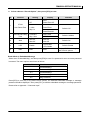
Dealer Mode 4: Scan Information
Select menu “Scan Inform”, then press [PF6] to enter Scan Information Mode. The menu options are
shown as follows:
Sub Menu
Menu Item
4.1
Scan Set
4.2
ZoneScanList
1. Select submenu “Scan Set”, then press [PF6] to enter.
No.
1
2
3
4
Function
Scan Type
Scan Restart
Setting
Display
Remarks
Single Zone
Scan
Scan
Single Zone
Multi-Zone
Scan
Scan
Multi Zone
Scan the added channel of zones
in multi-scan list
List Zone Scan
Scan
List Zone
Scan the added channel of zones
in current zone scan list
Time Operated
Scan
Time OP
Carrier
Operated
Scan
Carrier OP
Off
PRI 1
Off
Default
Fixed
PRI 1
Fixed
Dealer mode set
Selected
PRI 1
Selected
Always Set current CH as priority
CH
Operator
Select
PRI 1
Operator Sel
Set current CH as priority CH by
key operation (hold [scan], press
[MONI] 3 times
Off
PRI 2
Off
Default
Fixed
PRI 2
Fixed
Dealer mode set
Selected
PRI 2
Selected
Always Set current CH as priority
CH
PRI 2
Operator Sel
Set current CH as priority CH by
key operation (hold [scan], press
[MONI] 3 times
Priority Scan1
Priority Scan 2
Operator
Select
- 43 -
Scan the added channel of the
current zone
RMU800A SERVICE MANUAL
PRICH1 Off
Ch: Off, 1-512
1
Selector Knob: change a channel
or zone (default CH)
Channel
PRICH1
[PF5]: channel/zone
[PF4]: Priority CH On/Off
Off
PRICH2 Off
Ch: Off,1-512
1
Selector Knob: change a channel
or zone (default CH)
Channel
PRICH2
[PF5]: channel/zone
[PF4]: Priority CH On/Off
Both Off
PrioBoth Off
Priority 1 On
Priority 1 On
Priority 2 On
Priority 2 On
Both On
Prio Both On
Off
5
6
7
8
Priority Channel1 Zone
Priority Channel 2 Zone
Priority Ch
Temporary
Add/Del
10
1
Prio
Priority Ch detect CTC/DCS Off CTC/DCS Off
CTCSS/CDCSS
9
1
Look Back A
Look Back B
Prio
CTC/DCS On CTC/DCS
On
2.0s
Scan
LBTimeA 2.0S
0.5-5s
Scan
LBTimeA 0.5S
0.1s/1Step
Scan
LBTimeA 5.0S
2.0s
Scan
LBTimeB
2.0S
0.5-5s
Scan
LBTimeB
0.5S
0.1s/1Step
Scan
LBTimeB
5.0S
- 44 -
Detect carrier only at priority
channel
Carrier and Signal at priority
channel
The time period that radio returns
to a priority channel from a normal
channel when no carrier is being
received on the priority channel.
The time period that radio returns
to a priority channel from a normal
channel when signal is present on
priority channel but not matching
its signalling.
RMU800A SERVICE MANUAL
Scan
Last used (RX) Revert Call
Default
Scan
Last used (TX) Revert Used
11
12
13
14
15
Revert Channel
Revert Channel
Display
Dropout Delay
Time
Scan Dwell Time
Off Hook Scan
16 END
Selected
Scan
Revert
Selected +
TalkBack
Scan
SEL TalkBack
Priority 1
Scan
Revert PRIO1
Priority 1
+TalkBack
Scan
P1 TalkBack
Priority 2
Scan
Revert PRIO2
Priority 2
+TalkBack
Scan
P2 TalkBack
On
Revt
Display On
Off
Revt
Display Off
3s
Scan
DropOutT
3
1-300s
Scan
DropOutT
1
1s/1Step
Scan
DropOutT 300
3s
Scan
DwellT
3
1-300s
Scan
DwellT
1
1s/1Step
Scan
DwellT 300
Scan
Off
Hook Scan
Scanning is not controlled by hook
status
No Scan
Off
Hook No Scan
To scan, microphone must be on
hook
END
Display “END” indicating the end
of menu option
END
SEL
- 45 -
Default
Default
RMU800A SERVICE MANUAL
2. Select submenu “ZoneScan List”, then press [PF6] to enter.
No.
Function
1
Select a Zone
2
Zone Scan List
Enable/Disable
3
Add/Del
4
END
Setting
Display
100
Zone 100
List Enable
List Disable
Add
Zone
1 Add
Del
Zone
1 Del
END
END
Remarks
Selector Knob:select zone 1-256
Only existing zone can be set.
[PF6]: enter the second item
Only enabled list for zone list scan,
Selector Knob: change channel 1-512
Only existing zone can be added/
deleted.
[PF5]: ADD/DEL (save directly)
[PF6]: enter the first item
Display “END” to indicate the
end of menu option
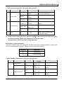
Dealer Mode 5: DTMF Set
Select menu “DTMF Set”, then press [PF6] to enter DTMF Set Mode. The menu options are shown as
follows:
Sub Menu
Menu Item
5.1
DTMF Encode
5.2
DTMF Decode
5.3
AutoDialList
5.4
PTT ID
1. Select submenu “DTMF Encode”, then press [PF6] to enter.
No.
1
Function
DTMF Speed
(Digital/Sec)
Setting
Display
6
DTMF
Speed
6
8
DTMF
Speed
8
10
DTMF
Speed
10
15
DTMF
Speed
15
- 46 -
Remarks
RMU800A SERVICE MANUAL
2
First Digit Time
0ms
1st
DT
0ms
100ms
1st
DT
100ms
500ms
1st
DT
500ms
1000ms
1st
DT
1000ms
*#
DT
0ms
100ms
*#
DT
100ms
500ms
*#
DT
500ms
1000ms
*#
DT
1000ms
200ms
Tx
RDT
200ms
100-1000ms
Tx
RDT
100ms
0ms
3
4
5
6
7
Digit Time
(*and#)
DTMF Transmit
Delay Time
Dial ID
DTMF Hold Time
Store & Send
First digit = first digit time + digit time
Default
10ms/1Step
First: Max (first digit time,*and# time) +
digit time
Not first: * and # time + digit time
Default
10ms/1Step
Default
Tx
RDT 1000ms
50ms/1Step
OFF
DTMF
Dial ID
Keypad dial BOT&EOT ID
PTT ID 1
DTMF
Dial ID 1
PTT ID 2
DTMF
Dial ID 2
PTT ID 3
DTMF
Dial ID 3
PTT ID 4
DTMF
Dial ID 4
OFF
DTMF
HoldTime Off
0.5-2.0S
Step 0.5s
Hold
Time
Off
0.5s
Hold
Time 2.0s
OFF
DTMF
Sto&Send Off
ON
DTMF
Sto&Send On
- 47 -
Default
RMU800A SERVICE MANUAL
8
D Key Assignment
D Code
DTMF
DKey D-Code
Pause1-16s
DTMF
DKeyPause
1
DTMF
DkeyPause 16
9
DTMF Side Tone
10
Auto Dial
11
Auto Dial
Programming
12
Manual Dial
13
14
Keypad Auto Tx
END
Side Tone Off
DTM F
SideTone Off
Side Tone On
DTM F
SideTone On
Auto Dial Off
AutoDial Off
Auto Dial On
AutoDial On
AutoDialP Off
AutoDP Off
AutoDialP On
AutoDP On
Manual Dial Off
ManuDial Off
Manual Dial On
ManuDial On
Auto Tx Off
KeyAutoTxOff
Not sent DTMF when only DTMF keys
are pressed.
Auto Tx On
KeyAutoTx On
Sent DTMF by pressing a DTMF
Keypad key
END
END
Hold [PTT], then dial
Display “END” indicating the end of
menu option
Notes:
1)
2)
3)
If a transmission starts with the "*" or "#" tone, the radio compares the tone duration with the set
"First Digit Time", and adapts the longer time of the two to the first "*" or "#" tone.
DTMF Transmit Delay Time sets the delay time from the starting of transmission to the sending of
the first DTMF digit. Making this value longer has a similar effect as setting the First Digit Time
longer. When using DTMF and CTCSS/CDCSS it is recommended to set this parameter to 100 ms
or more.
If automatic DTMF encode function (PTT ID, Auto Dial, Store & Send and Dial ID) is used for DTMF
Call, DTMF Speed must be set 6, 8 or 10 digits per second.
- 48 -
RMU800A SERVICE MANUAL
2.
Select submenu "DTMF Decode", then press [PF6] to enter.
No.
1
2
3
Function
Primary Code
Secondary Code
Setting
12345678
12345678
ABCDEF12
ABCDEF12
12345678
12345678
ABCDEF12
ABCDEF12
Off
Auto
RstTime Off
Auto Reset Time
1-300s
4
5
6
7
8
Primary Decode
Response
Secondary Decode
Alert Tone
END
Auto
RstTime 300S
Off
Ring
PDR
Ring
Alert
PDR
Alert
Transpond
PDR
Transpond
Alert & Tran
PDR
Alert & Tran
PDR
Alert Tone 1
PDR
Alert Tone 8
Off
SDR
None
Ring
SDR
Ring
Alert
SDR
Alert
Transpond
SDR
Transpond
Alert & Tran
SDR
Alert & Tran
Alert 1-8
END
Remarks
Auto
RstTime 1S
PDR
None
Primary Decode Alert
Alert 1-8
Tone
Secondary Decode
Response
Display
SDR
Alert Tone 1
SDR
Alert Tone 8
END
- 49 -
Ref. Alert Tone in Function Set Mode
Ref. Alert Tone in Function
Set Mode
Display “END” indicating the end of
menu options
RMU800A SERVICE MANUAL
3. Select submenu “AutoDialList”, then press [PF6] to enter.
No.
Function
1
Auto Dial No.
2
3
Auto Dial Name
Auto Dial Code
Setting
1-32
Step 1
AutoDial
1
AutoDial
32
ASCII CODE
Name
AutoDial
N
ABCD1234567890
12
4
Display
END
END
Remarks
Name
-----------
No input
Code
ABCD12345678
It will be scrolled as >=12
Code
-----------
No input
Display “END” indicating the
End of menu options
END
4. Select submenu “PTT ID”, then press [PF6] to enter.
No.
Function
1
PTT ID No.
2
3
4
5
PTT ID Type
BOT of PTT ID
EOT of PTT ID
END
Setting
Display
1-4
PTT ID
1
Step 1
PTT ID
4
BOT
PTT ID BOT
EOT
PTT ID EOT
BOTH
PTT ID BOTH
ABCD12345678
ABCD12345678
END
Remarks
BOT
ABCD12345678
It will be scrolled as >=12
BOT
-----------
No input
EOT
ABCD12345678
It will be scrolled as >=12
EOT
-----------
No input
END
- 50 -
Display “END” indicating the
End of menu options
RMU800A SERVICE MANUAL
Dealer Mode 6: 2-Tone Set
Select menu “2-Tone Set”, then press [PF6] to enter 2-Tone Set Mode. The menu options are shown as
follows:
Sub Menu
1.
Menu Item
6.1
2-Tone Encode
6.2
2-Tone Decode
6.3
2-Tone Option
Select submenu “2-Tone Encode”, then press [PF6] to enter.
No.
1
2
3
4
5
6
7
Function
2-Tone Code No.
Setting
1-32
Step 1
2-Tone
Name
2-Tone 1
--------
Name
--------
288.5-3100Hz
288.5-3100Hz
Tone A Duration
0.5-10.0s
Step 0.1s
Gap Duration
1
ASCII Code
Tone B Frequency
Tone B Duration
0.5-10.0s
Step 0.1s
0.0-2.0s
Step 0.1s
Remarks
2-Tone 32
2-Tone Code Name
Tone A Frequency
Display
No input
Step
A:
288.5Hz
Press [PF4] to switch between
0.1Hz/1Hz/10Hz/100Hz step
Step
A: 3100.0Hz
Step
B:
288.5Hz
Step
B: 3100.0Hz
Dur.
A:
0.5S
Dur.
A:
10.0S
Dur.
B:
0.5S
Dur.
B:
10.0S
Dur.
Gap:
0.0S
Dur.
Gap:
2.0S
- 51 -
Press [PF4] to switch between
0.1Hz/1Hz/10Hz/100Hz step
RMU800A SERVICE MANUAL
Off
8
Long A Duration
0.5-10.0s
9
2.
END
END
Dur.
Long:
Off
Dur.
Long:
0.5S
Dur.
Long: 10.0S
Display “END” indicating the end
of menu options
END
Select submenu “2-Tone Decode”, then press [PF6] to enter.
No.
Function
1
2-Tone Code No.
2
Decode 1 Format
Setting
1-8
Step 1
Display
2-Tone 1
2-Tone 8
A-B
Decode1: A-B
A-C
Decode1: A-C
A-D
Decode1: A-D
B-A
Decode1: B-A
B-C
Decode1: B-C
B-D
Decode1: B-D
C-A
Decode1: C-A
C-B
Decode1: C-B
C-D
Decode1: C-D
D-A
Decode1: D-A
D-B
Decode1: D-B
D-C
Decode1: D-C
Long A
Decode1:
A
Long B
Decode1:
B
Long C
Decode1:
C
- 52 -
Remarks
RMU800A SERVICE MANUAL
3
4
Decode 2 Format
Decode 3 Format
None
Decode2: None
A-B
Decode2: A-B
A-C
Decode2: A-C
A-D
Decode2: A-D
B-A
Decode2: B-A
B-C
Decode2: B-C
B-D
Decode2: B-D
C-A
Decode2: C-A
C-B
Decode2: C-B
C-D
Decode2: C-D
D-A
Decode2: D-A
D-B
Decode2: D-B
D-C
Decode2: D-C
Long A
Decode2:
A
Long B
Decode2:
B
Long C
Decode2:
C
None
Decode3: None
A-B
Decode3: A-B
A-C
Decode3: A-C
A-D
Decode3: A-D
B-A
Decode3: B-A
B-C
Decode3: B-C
B-D
Decode3: B-D
C-A
Decode3: C-A
C-B
Decode3: C-B
C-D
Decode3: C-D
D-A
Decode3: D-A
D-B
Decode3: D-B
D-C
Decode3: D-C
Long A
Decode3:
A
Long B
Decode3:
B
Long C
Decode3:
C
- 53 -
RMU800A SERVICE MANUAL
5
Decode 4 Format
None
Decode4: None
A-B
Decode4: A-B
A-C
Decode4: A-C
A-D
Decode4: A-D
B-A
Decode4: B-A
B-C
Decode4: B-C
B-D
Decode4: B-D
C-A
Decode4: C-A
C-B
Decode4: C-B
C-D
Decode4: C-D
D-A
Decode4: D-A
D-B
Decode4: D-B
D-C
Decode4: D-C
Long A
Decode4:
A
Long B
Decode4:
B
Long C
Decode4:
C
Step
A:
288.5Hz
6
Tone A Frequency
Press [PF4] to switch between
0.1Hz/1Hz/10Hz/100Hz step
288.5-3100Hz
Step
A: 3100.0Hz
7
8
Tone B Frequency
Tone C Frequency
288.5-3100Hz
288.5-3100Hz
Step
B:
288.5Hz
Step
B: 3100.0Hz
Step
C:
288.5Hz
Tone D Frequency
Press [PF4] to switch between
0.1Hz/1Hz/10Hz/100Hz step
Step
C: 3100.0Hz
Step
D:
288.5Hz
9
Press [PF4] to switch between
0.1Hz/1Hz/10Hz/100Hz step
Press [PF4] to switch between
0.1Hz/1Hz/10Hz/100Hz step
288.5-3100Hz
Step
D: 3100.0Hz
- 54 -
RMU800A SERVICE MANUAL
10
11
12
13
14
Call Response 1
Call Response 2
Call Response 3
Call Response 4
Decode 1
None
D1
None
Alert
D1
Alert
Transpond
D1
Transpond
Alert & Tran
D1
Alert & Tran
None
D2
None
Alert
D2
Alert
Transpond
D2
Transpond
Alert & Tran
D2
Alert & Tran
None
D3
None
Alert
D3
Alert
Transpond
D3
Transpond
Alert & Tran
D3
Alert & Tran
None
D4
None
Alert
D4
Alert
Transpond
D4
Transpond
Alert & Tran
D4
Alert & Tran
Tone A
D1
Tone A
Decode Code
D1
Decode Code
Alert Tone
Alert 1-8
D1
Alert Tone 1
D1
Alert Tone 8
- 55 -
Ref. “Alert Tone” in Function
Set Mode
RMU800A SERVICE MANUAL
15
Decode 2
Alert Tone
Tone A
D2
Tone A
Decode Code
D2
Decode Code
Alert 1-8
16
Decode 3
Alert Tone
Decode 4
Alert Tone
D3
Tone A
Decode Code
D3
Decode Code
19
20
Tone A Duration
Tone B Duration
Gap Duration
D3
Alert Tone 8
D4
Tone A
Decode Code
D4
Decode Code
0.5-10.0s
Step 0.1s
0.5-10.0s
Step 0.1s
0.0-2.0s
Step 0.1s
Off
21
D3
Alert Tone 1
Tone A
Alert 1-8
18
D2
Alert Tone 8
Tone A
Alert 1-8
17
D2
Alert Tone 1
Long A Duration
0.5-10.0s
D4
Alert Tone 1
D4
Alert Tone 8
Dur.
A:
0.5S
Dur.
A:
10.0S
Dur.
B:
0.5S
Dur.
B:
10.0S
Dur.
Gap:
0.0S
Dur.
Gap:
2.0S
Dur.
Long:
Off
Dur.
Long:
0.5S
Dur.
Long: 10.0S
- 56 -
Ref. “Alert Tone” in Function
Set Mode
Ref. “Alert Tone” in Function
Set Mode
Ref. “Alert Tone” in Function
Set Mode
RMU800A SERVICE MANUAL
22
3.
No.
END
END
Function
Setting
2-Tone Tx Rise Time
100-1000ms
Display
Rise
Time
200ms
Rise
Time
100ms
Rise
Time 1000ms
2
3
Display “END” indicating the end of
menu options
Select submenu “2-Tone Option”, then press [PF6] to enter.
200ms
1
++END
2-Tone Tx Tone
Auto Rese Time
Off
Tone Off
SideTone
SideTone
Short Beep
Short Beep
Off
RstTime OFF
1-300s
Auto
Remarks
Default
50ms/1Step
RstTime 1S
4
END
END
Display “END” indicating the end
of menu options
END
Dealer Mode 7: 5-Tone Set
Select menu “5-Tone Set”, then press [PF6] to enter 5-Tone Set Mode. The menu options are shown as
follows:
Sub Menu
Menu Item
7.1
Parameter
7.2
Encode Teleg
7.3
Encode Frame
7.4
EncodeOption
7.5
Decode Teleg
7.6
DecodeOption
- 57 -
RMU800A SERVICE MANUAL
1.
Select submenu “Parameter”, then press [PF6] to enter. Select Parameter 1-16 to set 5-Tone
parameters.
No.
1
Function
5-Tone Parameter
Setting
Display
Parameter1-16
Step 1
Parameter 1
Parameter 16
Remarks
Default: Parameter 1
SingleTone 0
2
SingleTone
SigleTone 0-F
Off
3
Connect ID
TxCode 1-32
SingleTone F
Default: SingleTone F
CNCT
Off
CNCT
ID TxCode 1
Default: Off
CNCT
ID TxCode 32
Off
4
Disconnect ID
TxCode 1-32
DCNT
Off
DCNT
ID TxCode 1
Default: Off
DCNT
ID TxCode 32
5
ZVEL1
TxRx
ZVEL1
ZVEL2
TxRx
ZVEL2
ZVEL3
TxRx
ZVEL3
PZVEI
TxRx
PZVEI
DZVEI
TxRx
DZVEI
PDZVEI
TxRx
PDZVEI
CCIR1
TxRx
CCIR1
CCIR2
TxRx
CCIR2
PCCIR
TxRx
PCCIR
TX/RX Address
Standard
- 58 -
Default
RMU800A SERVICE MANUAL
5
6
TX/RX Address
Standard
Decode Code 1
EEA
TxRx
EEA
Eurosignal
TxRx
Eurosignal
Natel
TxRx
NATEL
EIA
TxRx
EIA
MODAT
TxRx
MODAT
CCITT
TxRx
CCITT
USER DEFINED
TxRx
USER DEFINED
None
DC1
None
Decode Telegram
1-10
None
7
Decode Code 2
Decode Code 3
Decode Code 4
10
END
DC2
None
DC3
None
DC3
Decode Telegram Telegram 1
1-10
DC3
Telegram 10
None
9
DC1
Telegram 10
DC2
Decode Telegram Telegram 1
1-10
DC2
Telegram 10
None
8
DC1
Telegram 1
DC4
None
DC4
Decode Telegram Telegram 1
1-10
DC4
Telegram 10
END
END
- 59 -
Display “END” indicating the
end of menu options
RMU800A SERVICE MANUAL
4.
Select submenu “Encode Teleg”, then press [PF6] to enter.
No.
Function
1
5-Tone
EncodeTelegram
2
First Frame
Setting
Encode Telegram
1-32 Step 1
EncodeTel 1
EncodeTel 32
Disable
1stF
Disable
RxAdress
1stF
RxAdress
TxAdress
1stF
TxAdress
Frame 1-32
3
Display
Default: EncodeTelegram 1
Default: Disable
1st
Frame 1
1st
Frame 32
Disable
2ndF
Disable
RxAdress
2ndF
RxAdress
TxAdress
2ndF
TxAdress
Frame 1-32
2nd
Frame 1
Second Frame
Remarks
Default: Disable
2nd
Frame 32
4
Third Frame
Disable
3rdF
Disable
RxAdress
3rd F
RxAdress
TxAdress
3rd F
TxAdress
Frame 1-32
3rd t
Frame 1
3rd
Frame 32
- 60 -
Default: Disable
RMU800A SERVICE MANUAL
Disable
5
Transpond Decode
Decode Tel 1
DecodeTel 1-10
6
Disable
Decode Tel 10
Name
12345
TelegramName
Name
-----------7
3.
END
Default: Disable
END
END
Refer to Appendix 1 “Character
Input”
Display “END” indicating the
end of menu options
Select submenu “EncodeFrame”, then press [PF6] to enter.
No.
Function
1
Frame
2
5-Tone Standard
3
Frame Code
4
END
Display
Setting
Frame 1-32
Frame 1
Frame 32
ZVEL1
ZVEL1
ZVEL2
ZVEL2
ZVEL3
ZVEL3
PZVEI
PZVEI
DZVEI
DZVEI
PDZVEI
PDZVEI
CCIR1
CCIR1
CCIR2
CCIR2
PCCIR
PCCIR
EEA
EEA
Eurosignal
Eurosignal
Natel
NATEL
EIA
EIA
MODAT
MODAT
CCITT
CCITT
USER DEFINED
USER DEFINED
12345
Fcode 12345
END
END
- 61 -
Remarks
Default: Frame 1
Default: ZVEL1
Default:FFFFF
Display “END” indicating the end
of menu options
RMU800A SERVICE MANUAL
4.
Select submenu “EncodeOption”, then press [PF6] to enter.
No.
1
2
3
4
5
6
7
8
9
10
Function
5-Tone Delay 1
5-Tone Delay 2
5-Tone Delay 3
5-Tone
End Delay
5-Tone
Transpond Delay
5-Tone
First Tone Length
5-Tone Delay
2Tone
5-Tone Delay
3Tone
5-Tone Side Tone
5-Tone Monitor
Setting
0-7000ms
Step 10ms
0-7000ms
Step 10ms
0-7000ms
Step 10ms
0-7000ms
Step 10ms
0-7000ms
Step 10ms
0-7000ms
Step 10ms
Display
Remarks
1st
Delay 0ms
Default: 100ms
1st
Delay 7000ms
2nd
Delay 0ms
Default: 300ms
2nd
Delay 7000ms
3rd
Delay 0ms
Default: 300ms
3rd
Delay 7000ms
End
Delay 0ms
Default: 100ms
End
Delay 7000ms
Tspd
Delay 0ms
Default: 1000ms
Tspd
Delay 7000ms
1st
ToneL 0ms
Default: 1000ms
1st
ToneL 7000ms
Off
D2ToneOff
0-9,A-F
Step 1
Delay2Tone 0
Off
D3ToneOff
0-9,A-F
Step 1
Delay3Tone 0
Side Tone On
Side Tone On
Side Tone Off
Side Tone Off
Monitor On
Monitor On
Monitor Off
Monitor Off
Default: Off
Delay2Tone F
Default: Off
Delay3Tone F
- 62 -
Default: Off
Default: On
RMU800A SERVICE MANUAL
11
5.
END
Display “END” indicating the
end of menu options
END
END
Select submenu “Decode Telegr”, then press [PF6] to enter.
No.
Function
1
5Tone
Decode Telegram
2
3
4
5Tone Standard
Frame 1
Display
Setting
DecodeTel 1
Decode Telegram
1-10
Decode Tel 10
ZVEL1
ZVEL1
ZVEL2
ZVEL2
ZVEL3
ZVEL3
PZVEI
PZVEI
DZVEI
DZVEI
PDZVEI
PDZVEI
CCIR1
CCIR1
CCIR2
CCIR2
PCCIR
PCCIR
EEA
EEA
Eurosignal
Eurosignal
Natel
NATEL
EIA
EIA
MODAT
MODAT
CCITT
CCITT
USER DEFINED
USER DEFINED
None
F1
None
Normal
Nor
FFFFFFFF
Rx Address
F1
Rx Address
Single
F1
Single Tone
None
F2
None
Normal
Nor
FFFFFFFF
Rx Address
F2
Rx Address
Single
F2
Single Tone
Frame 2
Remarks
- 63 -
Default: ZVEL1
Default: None
Default: None
RMU800A SERVICE MANUAL
5
6
7
8
9
Frame 3
Monitor
Stun
Scan
Transpond
None
F3
None
Normal
Nor
FFFFFFFF
Rx Address
F3
Rx Address
Single
F3
Single Tone
Disable
Moni Disable
Close
Moni Close
Open
Moni Open
Disable
Stun Disable
Stun
Stun Enable
Revive
Stun Revive
Kill
Stun Kill
Disable
Scan Disable
Start
Scan Start
Stop
Scan Stop
None
None
Encode
EncodeTel 1
Telegram1-32
EncodeTel 32
Alert Tone
11
Group
Alert Tone
12
END
Default: Open
Default: Disable
Default: Disable
Default: None
IndAlert Off
Individual
10
Default: None
IndivdAlert1
Alert 1-8
IndivdAlert8
Off
GrpAlert Off
GroupAlert 1
Alert 1-8
END
GroupAlert 8
END
- 64 -
Display “END” indicating
the end of menu options
RMU800A SERVICE MANUAL
6.
Select submenu “Decode Option”, then press [PF6] to enter.
No.
Function
Setting
Off
1
5 Tone
Auto Reset Time
1-180s
Step 1s
Display
Remarks
Auto
Reset Time Off
Auto
ResetTime1
Auto
ResetTime180
0-2550ms
Step 10ms
NDDT 2550ms
Default: Off
2
Next Decode Delay
Time
3
Alert
Alert On
Alert Off
Alert On
Alert Off
Default: On
4
LED
Enable
LED Enable
LED Disable
Default: Enable
5
END
END
END
NDDT 0ms
Default: 1600ms
Display “END” indicating the
end of menu options
Dealer Mode 8: Embedded Message
Select menu “Embedded Msg”, and then press [PF6] to enter if no password is set or a correct password
is entered. The menu options are shown as follows:
Sub Menu
Menu Item
8.1
EmbeddedMsg1
8.2
EmbeddedMsg2
8.3
EmbeddedMsg3
8.4
EmbeddedMsg4
8.5
Msg Password
Press [PF6] to enter any of the above menu options, the selected embedded message or message
password would be displayed. Then press [PF1] to edit the embedded message or message password.
Please refer to Appendix 1 “Character Input”.
- 65 -
RMU800A SERVICE MANUAL
Dealer Mode 9: Emergency Set
Select menu “Emergency Set”, then press [PF6] to enter.
No.
Function
1
Emergency Zone
Emergency CH
2
3
4
5
6
Emergency Cycle
Emergency Key
Delay Time
Tx Duration
Rx Duration
Emergency Type
Setting
Zone: 1-256
CH: 1-512
8
Emergency ID
Emergency Led
Selector Knob: change a
channel or zone (default ch)
1
CH 100
[PF5]: channel/zone
Continuous
Cycle Contin
1-200
Cycle
1
Step 1
Cycle
200
Off
Key
Deley
Off
0.1-5.0s
Key
Deley
0.1S
Step 0.1s
Key
Deley
5.0S
20s
Tx
Dur.
20S
Tx
Dur.
1S
Tx
Dur.
60S
20s
Tx
Dur.
20S
1-180s
Tx
Dur.
1S
Step 1s
Tx
Dur.
180S
Off
Type
Off
DTMF
Type
DTMF
MSK
Type
MSK
1-60s
Step 1s
ID
-----------------------
----------------------7
Remarks
Display
0000000000000000
9999999999999999
ID
0000000000000000
ID
9999999999999999
Off
LED
Off
On
LED
On
- 66 -
Default data
Default data
No input
RMU800A SERVICE MANUAL
Emergency
9
10
11
Display Text
Emergency Mode
Tone 1 Duration
----------------------
Tex t
----------------------
No Text to be Displayed
Emergency
Tex t
Emergency
Max 12
Silent
Mod e
Silent
Audible
Mod e
Audible
0-255s
Step 1s
12
Tone 2 Duration
0-255s
Step 1s
13
END
END
Ton e
1 Dur.
0S
Ton e
1 Dur.
255S
Ton e
2 Dur.
0S
Ton e
2 Dur.
255S
END
Display “END” indicating the
end of menu options
Dealer Mode 10: STUN Inform
Select menu “Stun Inform”. Press [PF6], the radio enters Stun Information Mode if no password is set or
a correct password is entered.
Sub Menu
Menu Item
10.1
Stun Set
10.2
Stun Password
- 67 -
RMU800A SERVICE MANUAL
1.
Select submenu ‘Stun Set”, then press [PF6] to enter.
No.
1
2
3
2.
Function
Stun Encode
Stun Response
END
Setting
Display
------------
Stun
Disable
0000000
Stun
0000000
~FFFFFFF
Stun
FFFFFFF
TX Inhibit
Stun
TX Inhibit
TX/RX Inhibit
Stun
TXRX Inhibit
Kill
Stun
Kill
END
Remarks
No encode, disable Stun
Default
Display “END” to indicate the
end of menu options
END
Select submenu “Stun Password”, then press [PF6] to view the password. Then press [PF1]
to edit the password. Please refer to Appendix 1 “Character Input”.
The password is numeric digit only, 8 digits maximum.
Dealer Mode 11: Mode Information
Select menu “Mode Inform”, then press [PF6], the radio enters Mode Information Mode if no password is
set or a correct password is entered. The menu options are shown as follows:
Sub Menu
Menu Item
11.1
Mode Select
11.2
Mode Password
1. Select submenu “Mode Select”, then press [PF6] to enter.
No.
Function
User Set Mode
1
2
Channel Set Mode
Setting
Display
OFF
Mode
UserSet
Off
ON
Mode
UserSet
On
OFF
Mode
CHSet
Off
ON
Mode
CHSet
On
- 68 -
Remarks
Default
Default
RMU800A SERVICE MANUAL
3
4
5
6
7
8
9
10
11
12
Zone Information Mode
Function Set Mode
Scan Information Mode
DTMF Set Mode
2-Tone Set Mode
5-Tone Set Mode
Embedded Message Mode
Emergency Set Mode
Stun Set Mode
Test Mode
OFF
Mode
ZoneSet Off
ON
Mode
ZoneSet
On
OFF
Mode
FuncSet
Off
ON
Mode
FuncSet
On
OFF
Mode
ScanSet
Off
ON
Mode
ScanSet
On
OFF
Mode
DTMFSet Off
ON
Mode
DTMFSet On
OFF
Mode
2ToneSet Off
ON
Mode
2ToneSet On
OFF
Mode
5ToneSet Off
ON
Mode
5ToneSet On
OFF
Mode
EmbedMsg Off
ON
Mode
EmbedMsg On
OFF
Mode
Emergency Off
ON
Mode
Emergency On
OFF
Mode
Stun Set Off
ON
Mode
Stun Set On
OFF
Mode
LocalTestOff
ON
Mode
LocalTest On
- 69 -
Default
Default
Default
Default
Default
Default
Default
Default
Default
Default
RMU800A SERVICE MANUAL
13
Clone Mode
Model Set Mode
14
Firmware Download
Mode
15
16
17
Firmware Version
Display
END
OFF
Mode
WireCloneOff
ON
Mode
WireClone On
OFF
Mode
ModelSel Off
ON
Mode
ModelSel On
OFF
Prog
FirmWare Off
ON
Prog
FirmWare On
OFF
Ver
Version Off
ON
Ver
Version On
END
END
Default
Default
Default
Default
Display “END” indicating
the end of menu options
2. Select submenu “DBD Password”, then press [PF6] to view the password. Then press [PF1]
to edit the password. Please refer to Appendix 1 “Character Input”.
The password is numeric digit only, 8 digits maximum.
Test Mode
1. Turn power on while holding down [PF2], the radio enters Test Mode. Frequency test channel
and signalling test channel are displayed.
- 70 -
RMU800A SERVICE MANUAL
In this mode, the channel frequency (center, low, high) can be modified through the programming software.
CH1 ( C) CH 2 ( L ) CH 3 ( H )
CH 4
CH 5
CH 6
CH 7
CH 8
RX(MHz)
155.15
136.15
173.85
145.55
164.55
155.00
155.20
155.40
(V)
TX(MHz)
155.00
136.00
174.00
145.50
164.50
155.00
155.20
155.40
1
RX(MHz)
481.15
450.15
511.85
465.55
496.55
481.00
481.20
481.40
(U2)
TX(MHz)
481.00
450.00
512.00
465.50
496.50
481.00
481.20
481.40
2
RX(MHz)
375.15
350.15
399.85
362.55
387.55
375.00
375.20
375.40
(U5)
TX(MHz)
375.00
350.00
400.00
362.50
387.50
375.00
375.20
375.40
3
RX(MHz)
435.15
400.15
469.85
417.55
452.55
435.00
435.20
435.40
(U1)
TX(MHz)
435.00
400.00
470.00
417.50
452.50
435.00
435.20
435.40
4
RX(MHz)
465.15
440.15
489.85
452.55
477.55
465.00
465.20
465.40
(U4)
TX(MHz)
465.00
440.00
490.00
452.50
477.50
465.00
465.20
465.40
5
RX(MHz)
503.15
480.15
525.85
491.75
515.25
503.00
503.20
503.40
(U3)
TX(MHz)
503.00
480.00
526.00
491.70
515.20
503.00
503.20
503.40
6
RX(MHz)
425.15
400.15
449.85
412.55
437.55
425.00
425.20
425.40
(U6)
TX(MHz)
425.00
400.00
450.00
412.50
437.50
425.00
425.20
425.40
Model
RX/TX
0
Signallings are shown as follows:
No.
RX
TX
Description
1
None
None
2
None
100Hz square wave
3
CTCSS 67.0Hz
CTCSS 67.1Hz
4
CTCSS 151.4Hz
CTCSS 151.4Hz
5
CTCSS 210.7Hz
CTCSS 210.7Hz
6
CTCSS 250.3Hz
CTCSS 250.3Hz
7
CDCSS 023N
CDCSS 023N
8
CDCSS 754I
CDCSS 754I
9
DTMF (159D)
DTMF (159D)
10
None
DTMF 9
11
2-tone 321.7/928.1
None
Tone duration: 1s/1s
12
Single tone 1200Hz
Single tone 1200Hz
Tone duration: 4s
13
None
Single tone 1000Hz
14
MSK
MSK
- 71 -
RMU800A SERVICE MANUAL
2.
In Test Mode, the following functions can be accomplished by key pressing.
Key
Function
Up
Volume Up
Down
Description
Volume down
PF1
Wide band/Narrow band
PF2
Squelch Open/Close
PF3
Test Mode/ Adjustment Mode
“
PF4
Activate compander function
PF5
Signalling Up
PF6
Signalling Down
Selector Knob
Channel Up/Down
” icon appears when squelch is opened.
PF1: compander on/off
PF2: clock shift on/off
PF3: 1200/2400bps MSK
In Test Mode, press [PF4], then press the following key to enable the corresponding functions.
3.
PF1
Compander On/Off
“▼” icon appears when compander is turned On
PF2
Clock shift On/Off
“A” icon appears when clock shift is turned On
PF3
1200/2400bps MSK
“
PF4
Return to Test Mode
PF5
None
PF6
None
” icon appears when 2400bps is selected
In Test Mode, press [PF3] to enter Adjustment Mode. Turn the Selector Knob to choose your
desired setting items.
No.
Dealer Mode
LCD Display
1
Frequency stability
Frequency
2
TX power
Tx Power
3
Max. deviation
Max.Deviate
4
CDCSS balance
CDCSSBalance
5
CTCSS deviation
CTCSSDeviate
6
CDCSS deviation
CDCSSDeviate
7
DTMF deviation
CDCSSDeviate
8
MSK deviation
MSK Deviate
9
Single tone deviation
Tone Deviate
10
RX sensitivity
Rx Sensitivi
12
SQL close
Close SQL
- 72 -
RMU800A SERVICE MANUAL
In Test Mode, user can press the following key to switch models.
①
Press [PF3] to toggle between Test Mode and Adjustment Mode.
Press [PF4] to toggle between Adjustment Mode and Model Set Mode ([PF4] is invalid if Model
Set Mode is inhibited by your dealer. Refer to “Model Set Mode” for details).
②
Press [PF6] to enter the selected mode.
4.
In Adjustment Mode, the following functions can be accomplished by key pressing.
Key
Function
Up
Volume Up
Down
Volume down
PF1
Return to Adjustment Item menu
PF2
Squelch Open/Close
PF4
Enter the previous item (Down)
PF5
Enter the next item (Up)
PF6
Save the settings, enter the next item
Selector Knob
Description
“
Adjust upwards/downwards
- 73 -
” icon appears when squelch is opened.
RMU800A SERVICE MANUAL
5.
Setting Items (***:1-256)
Setting Item
CDCSS Balance
Wideband/
Narrowband
Wide
Narrow
Frequency
__C
100Hz square wave
Low
CDCSS BAL ***
__L
100Hz square wave
High
CDCSS BAL ***
__H
100Hz square wave
CDCSS BAL ***
N_C
100Hz square wave
67.0 DEV ***
__C
CTCSS: 67.0Hz
__L
CTCSS: 67.0Hz
__H
CTCSS: 67.0Hz
N_C
CTCSS: 67.0Hz
__C
CTCSS: 151.4Hz
__L
CTCSS: 151.4Hz
__H
CTCSS: 151.4Hz
n_C
CTCSS: 151.4Hz
__C
CTCSS: 254.1Hz
__L
CTCSS: 254.1Hz
__H
CTCSS: 254.1Hz
254.1 DEV ***
n_C
CTCSS: 254.1Hz
Center
CDCSS DEV ***
__C
CDCSS: 023N
Low
CDCSS DEV ***
__L
CDCSS: 023N
High
CDCSS DEV ***
__H
CDCSS: 023N
CDCSS DEV ***
n_C
CDCSS: 023N
Center
Low
Center
Center
CTCSS Deviation
Wide
Low
High
Narrow
Center
Center
Wide
Low
High
Narrow
CDCSS Deviation
Wide
Narrow
DTMF Deviation
MSK Deviation
Single Tone Deviation
Wide
Narrow
Wide
Narrow
Wide
Narrow
-
RX Sensitivity
-
Description
CDCSS BAL ***
High
Narrow
Sub LCD
Center
Center
Wide
Main LCD
Center
Center
Center
Center
67.0 DEV ***
67.0 DEV ***
67.0 DEV ***
151.4 DEV ***
151.4 DEV ***
151.4 DEV ***
151.4 DEV ***
254.1 DEV ***
254.1 DEV ***
254.1 DEV ***
DTMF DEV
***
DTMF DEV ***
Center
MSK DEV
***
Center
MSK DEV
***
Center
Center
DTMF: 9
n__
DTMF: 9
0XAAA…
n__
Tone DEV ***
0XAAA…
1KHz
Tone DEV ***
n__
1KHz
Sensiti
***
__L
No signalling,SQ off
Center/Low Sensiti
***
_CL
No signalling,SQ off
Sensiti
***
__C
No signalling,SQ off
High/Center Sensiti
***
_HC
No signalling,SQ off
***
__H
No signalling,SQ off
Low
Center
High
Sensiti
- 74 -
RMU800A SERVICE MANUAL
SQL 9
Wideband
SQL Open
SQL 9
Narrowband
SQL3
Wideband
SQL3
Narrowband
SQL 9
Wideband
SQL 9
Narrowband
SQL Close
SQL3
Wideband
SQL3
Narrowband
Center
OpenSQL9
***
__C
No signalling
Low
OpenSQL9
***
__L
No signalling
OpenSQL9
***
__H
No signalling
OpenSQL9
***
n_C
No signalling
High
Center
Center
OpenSQL3
***
__C
No signalling
Low
OpenSQL3
***
__L
No signalling
High
OpenSQL3
***
__H
No signalling
OpenSQL3
***
n_C
No signalling
Center
Center
CloseSQL9
***
__C
No signalling
Low
CloseSQL9
***
__L
No signalling
CloseSQL9
***
__H
No signalling
CloseSQL9
***
n_C
No signalling
High
Center
Center
CloseSQL3
***
__C
No signalling
Low
CloseSQL3
***
__L
No signalling
High
CloseSQL3
***
__H
No signalling
Center
CloseSQL3
***
n_C
No signalling
- 75 -
RMU800A SERVICE MANUAL
Model Set Mode
1.
2.
3.
4.
5.
6.
Turn power on while holding down [PF2], the radio enters Test Mode. The frequency test channel
and signalling test channel are displayed.
In Test Mode, press [PF3] to enter Adjustment Mode.
In Adjustment Mode, press [PF4] to enter Model Set Mode. “DESTINATION” and the model No.
are displayed.
Turn the Selector Knob to choose model 1-6.
Press [PF6] to confirm.
Press [PF3] to return to Test Mode.
Notes:
1.
Once the new model is set, previous channel settings (frequency, CTCSS/CDCSS, channel
function settings) will be deleted, and part of functions are also changed. Therefore, do not make
this operation unless it’s very necessary, such as changing the EEPROM or FLASHROM, etc.
2.
Initial Data Table
Model
RX/TX
CH 1
(Center )
CH 2
(Low)
CH 3
(High )
CH 4
CH 5
CH 6
CH 7
CH 8
0
(V)
RX(MHz)
155.15
136.15
173.85
145.55
164.55
155.00
155.20
155.40
TX(MHz)
155.00
136.00
174.00
145.50
164.50
155.00
155.20
155.40
1
(U2)
RX(MHz)
481.15
450.15
511.85
465.55
496.55
481.00
481.20
481.40
TX(MHz)
481.00
450.00
512.00
465.50
496.50
481.00
481.20
481.40
2
(U5)
RX(MHz)
375.15
350.15
399.85
362.55
387.55
375.00
375.20
375.40
TX(MHz)
375.00
350.00
400.00
362.50
387.50
375.00
375.20
375.40
3
(U1)
RX(MHz)
435.15
400.15
469.85
417.55
452.55
435.00
435.20
435.40
TX(MHz)
435.00
400.00
470.00
417.50
452.50
435.00
435.20
435.40
4
(U4)
RX(MHz)
465.15
440.15
489.85
452.55
477.55
465.00
465.20
465.40
TX(MHz)
465.00
440.00
490.00
452.50
477.50
465.00
465.20
465.40
5
(U3)
RX(MHz)
503.15
480.15
525.85
491.75
515.25
503.00
503.20
503.40
TX(MHz)
503.00
480.00
526.00
491.70
515.20
503.00
503.20
503.40
6
(U6)
RX(MHz)
425.15
400.15
449.85
412.55
437.55
425.00
425.20
425.40
TX(MHz)
425.00
400.00
450.00
412.50
437.50
425.00
425.20
425.40
- 76 -
RMU800A SERVICE MANUAL
Circuit Description
1.
Frequency Configuration
The receiver utilizes double conversion superheterodyne. The first IF is 73.05MHz and the second is
450KHz. The first local oscillator signal is supplied by PLL circuit. The second local oscillator signal
(73.5MHz) is generated from TCXO (73.5MHz); The PLL circuit also generates the frequencies needed
in the transmitter (See Fig.1).
Frequency Range: 450 MHz—512MHz
2.
Receiver Circuit
The receiver section configuration is shown as Fig. 1.
Figure 1 Receiver Section Configuration
2.1
RF AMP BPF
It consists of BPF (D603, D602, D601) and RF amplifier (Q601). The range of bandpass frequency (U1:
400 MHz—470MHz;U2: 450 MHz—512MHz U3: 480 MHz—526MHz;U4: 440 MHz—490MHz;U5: 350
MHz—400MHz). The signal is filtered by the RF Amp BPF to eliminate unwanted signals before going to
the first mixer.
2.2
The First Mixer
The signal from RF AMP BPF is mixed with the first local oscillator signal from PLL circuit in the
double-balance mixer (Q138, Q144, Q145, Q146) to generate a 73.05MHz first IF signal. The first IF
signal is then fed through two crystal filters (N: XF101, XF103; W: XF102, XF104) to further remove
spurious signals.
- 77 -
RMU800A SERVICE MANUAL
2.3
IF Amplifier
The first IF signal is amplified by Q125, Q118 and then enters IC119(TA31136FN). The signal is mixed
with the second local oscillator signal (73.05MHz) to create a 450KHz second IF signal. The second IF
signal is then fed to a ceramic filter (N: CF101, CF103; W: CF102, CF104) to eliminate unwanted signals.
The resulting signal is detected by IC119 and output from Pin9 as an AF signal.
2.4
AF Amplifier
The AF signal from IC119 is amplified by IC109 before being filtered. The resulting AF signal passes
through Q108(AF MUTE)and IC121(electronic switch) , then is amplified by IC106 ( the received
signalling is inputted into CPU for decoding) and IC104. The amplified signal is fed to IC125 (volume
control) and Q114 (SP MUTE) before entering AF AMP (IC126). The outputted AF signal is then delivered
to the speaker through control panel.
2.5
Squelch
The AF signal from IC119 is amplified by IC109 again, and then filtered to remove noise signals. The
noise signal is amplified by Q121 and rectified by D110 to produce an ASQ level. The ASQ level is then
compared in CPU (IC120) to generate a level which controls AF MUTE and SP MUTE. IC120 determines
whether to output sounds from the speaker by controlling Q108, Q114.
3. Transmitter Circuit
Figure 2 Transmitter Section Configuration
3.1
MIC Circuit and Modulation Circuit
The AF signal from MIC is amplified by IC104 after passing through the MIC control switch (Q507). The
resulting signal is then amplified by IC106 and pre-emphasized, encoded. It is passed to IC121
(electronic switch) before reaching IC125. The signalling is inputted into IC125 and enters VCO for
modulation.
- 78 -
RMU800A SERVICE MANUAL
3.2
Driver and Final Power Amplifier Circuit
TX-RF signal is outputted from Q703 in VCO circuit and amplified by Q126, Q127 and Q128. The
amplified signal is then fed to IC102 (Power Module) and passes through LPF before reaching the
antenna terminal.
3.3
APC
The APC is used to keep the power output at a constant preset value. D105 and D106 transform the
signal from detector into DC voltage which is then compared with the reference voltage from CPU in
IC118 and outputted as DC control voltage. The DC control voltage controls the output power by
controlling the grid of IC102.
4.
PLL Circuit
PLL circuit generates the first local oscillator signal for reception and the RF signal for transmission. PLL
circuit consists of TX frequency oscillator (Q701), RX frequency oscillator (Q702), buffer amplifier
(Q703), RF amplifier (Q124), PLL IC (IC801), LPF (Q804, Q805) and TX/RX VCO control switch (Q704,
Q706).
In transmit mode, IC120 transmits the frequency data to PLL IC. Q704 is turned on to activate TX VCO.
The outputted signal is amplified by Q703, Q124, and then divided by PLL IC into 2.5KHz, 5KHz or
6.25KHz signal. The divided signal is compared with 2.5KHz, 5KHz or 6.25KHz reference signal from
16.8MHz crystal oscillator (2.5 PPM frequency stability) in the phase comparator. The frequency control
voltage outputted from the phase comparator is sent to TX VCO after passing through LPF (Q804,
Q805). In the meantime, modulation signal (TX) is passed to TX VCO for frequency modulation.
The working principle in receive mode is similar to that in transmit mode.
Figure 3 PLL Circuit
- 79 -
RMU800A SERVICE MANUAL
5. Control Circuit
Circuit in this section is comprised of CPU, reset IC, power supply controller and flash ROM.
5.1
CPU
IC120 (CPU) operates at 9.8304MHz. It controls the data transmission between receive circuit, transmit
circuit, control circuit, display circuit and peripheral circuit.
Figure 4 Control Circuit
5.2
Power Supply
Power supply of the radio is derived from the battery which supplies battery B+. D135 and D137 are
over-voltage protection Diodes. Power-on/off can be controlled by software.
Figure 5 Power Switch Circuit
- 80 -
RMU800A SERVICE MANUAL
Vout provides power supply to IC115, IC114, IC113, and IC111, which produces 8V, 9V, 5V, and 3.3V
voltage to the circuit.
6.
Display Circuit
Display circuit is comprised of CPU (IC503), LCD module, LED and other components. Radio features
are programmable by PF1-PF6. Data is displayed on the 12-digit and 4-digit dot matrix LCD in
alphanumeric form.
Figure 6 Display Circuit
- 81 -
RMU800A SERVICE MANUAL
Semiconductor Data
1. Voltage Supply: TA7805F (Display Unit IC501): Providing supply voltage.
2. Voltage Detector: R3111H421C(Display Unit IC502)
2-1.Pin Function
Pin No.
Name
I/O
Function
1
Vout
O
Reset.
2
GND
3
Vin
GND.
I
Supply voltage.
3. Display CPU: UPD780112(Display Unit IC503)
3-1.Pin Function
Pin No.
Name
I/O
Function
1
AVref
+5V.
2
AVss
GND.
3
IC(vpp)
Internal connected.
4
VDD
+5V.
5
Vss
GND.
6
X1
7
X2
8
RESET
9
XT1
+5V.
10
XT2
Not used.
11
SHIFT
Beat Shift.
12
Mute
MIC Mute.
13
RSW3
Not used.
14
RSW2
Not used.
15
RSW0(DN)
I
Rotary SW0 (down).
16
RSW1(UP)
I
Rotary SW1 (up).
17
LCDBL
O
LCD backlight.
18
LCDCS
O
LCD control signal output.
19
LCDSOD
O
LCD data read.
20
LCDDAT
O
LCD data write.
21
LCDCLK
O
Clock output for LCD driver.
22
EVss
GND.
23
EVdd
+5V.
24
MICDAT
25
OUT1
26
RXD1
I
Serial data input.
27
TXD1
O
Serial data output.
Connection to crystal.
I
O
CPU reset.
Serial data output for keypad MIC.
Not used.
- 82 -
RMU800A SERVICE MANUAL
28
HMBL
MIC backlight control signal output.
29
HOOK/RXD0
Hook signal input/ Serial data input.
30
TXD0
O
PC commands (TXD)/connects to PTT.
31
RLED
O
Red LED output.
32
GLED
O
Green LED output.
33
PTT
O
PTT/connect to TXD0.
34
DNKEY
I
Up key.
35
UPKEY
I
Down key.
36
KEYBL
I
Key backlight.
37
IN1
Not used.
38
IN2
Not used.
39
PF6
I
PF6 Key Input.
40
PF5
I
PF5 Key Input.
41
PF4
I
PF4 Key Input.
42
PF3
I
PF3 Key Input.
43
PF2
I
PF2 Key Input.
44
PF1
I
PF1 Key Input.
4. Flash ROM: AT29C020-90T1(TX-RX Unit IC103)
4-1 Pin Function
Pin No.
Name
I/O
Function
1~6, 9~20, 31
A18~A0
I
Flash ROM address bus.
7
WR
I
Flash ROM write enable.
8
VCC
21~23, 25~29
D0~D7
24
VSS
30
CE
I
Flash ROM chip enable.
32
OE
I
Flash ROM output enable.
+5V.
I/O
Flash ROM data bus.
GND.
5. EEPROM: AT2408N12.5S(TX-RX Unit IC105)
5-1 Pin Function
Pin No.
Name
I/O
Function
1~3
A0~A2
I
4
GND
5
SDA
6
SCL
7
TEST
Test.
8
VCC
+5V.
Address inputs.
GND.
I/O
Serial Data.
Serial clock input.
- 83 -
RMU800A SERVICE MANUAL
6. Audio processor: AK2346 (TX-RX Unit IC106)
6-1 Pin Function
Pin No.
Name
I/O
Function
1
AGNDIN
I
Analog ground input pin.
2
AGND
O
Analog ground output pin.
3
TXIN
I
Transmit audio signal input pin.
4
TXINO
O
TXA1 feedback output pin.
5
LIMLV
I
Limit level adjuster pin.
6
EXTLIMIN
I
External signal input pin pre-limiter circuit.
7
MOD
O
The modulated transmit signal output pin.
8
VSS
9
TCLK
10
TDATA
GND.
O
Clock output pin for MSK transmission data.
I
MSK transmission data input pin.
Data are latched synchronizing with the TCLK rising edge.
11
DI/O
I/O
Serial data input and output pin.
Input for register setting data and output for MSK receive data.
12
RDF/FC
O
MSK signal received flag and frame detection signal output pin.
13
SCLK
I
Clock input pin for serial data I/O.
14
DIR
I
Serial data I/O control pin.
15
XOUT
I
Crystal oscillator connecting input pin.
16
XIN
17
VDD
18
EXPOUT
O
Expander and VR4 output pin.
19
RXAFIN
I
Receive audio signal input pin.
20
RXAF
O
Receive audio signal output pin.
21
RXLPFO
O
Receive LPF output pin.
22
RXINO
O
RXA1 feedback output pin.
23
RXIN
I
Demodulated audio signal input pin.
24
TEST
I
Test register control input pin.
I/O
Crystal oscillator connecting input and output pin.
Positive power supply pin.
- 84 -
RMU800A SERVICE MANUAL
7. DTMF Receiver: LC73872M (TX-RX Unit IC122)
7-1 Pin Function
Pin No.
Name
I/O
Description
1
INPUT
I
Signal input.
2
NC
3
PD
I
The IC goes to lower power mode when this pin is pulled high.
4
OSCO
O
Oscillator output.
5
OSCI
I
Oscillator input.
6
NC
No connection.
7
VSS
GND.
8
LOAD
No connection.
I
Inputting a clock to this pin allows the serial data to be output two
or more times.
9
SD
O
The decoded DTMF signal is output.
10
ACK
I
Shifting out data from SD pin.
11
STD
O
A high level indicates the presence of a DTMF signal.
12
EST
O
A high level indicates the presence of a DTMF signal.
13
NC
No connection.
14
VDD
+5V.
8. D/A converter with buffer amplifier: M62364FP (TX-RX Unit IC125)
8-1 Pin Function
Pin No.
Name
I/O
Description
1,4,9,12,13,16,21,24
VIN1~VIN8
I
D/A converter input.
2,3,10,11,14,15,22,23
VOUT1~VOUT8
O
D/A converter output with 8-bit resolution.
5
VDD
+5V.
6
LD
I
A low state enables data loading to shift register.
7
CLK
I
Shift clock input.
8
DI
I
Serial data input.
17
DO
O
Serial data output.
18
VDAref
I
D/A Converter reference voltage input.
19
RESET
I
Reset 8-bit latches.
20
GND
GND.
- 85 -
RMU800A SERVICE MANUAL
9. Power amplifier: TDA8561Q (TX-RX Unit IC126)
9-1 Pin Function
Pin No.
Name
I/O
Description
1
-INV1
I
2
GND(S)
3
INV2
4
RR
Supply voltage ripple rejection.
5
VP1
Supply voltage.
6
OUT1
7
GND1
8
OUT2
9
NC
10
OUT3
11
GND2
12
OUT4
13
VP2
14
MODE
I
Mode select switch input.
15
INV3
I
Inverting input 3.
16
VDIAG
O
Diagnostic output.
17
-INV4
I
Non-inverting input 4.
Non-inverting input 1.
Signal ground.
I
O
Inverting input 2.
Output 1.
Power ground 1.
O
Output 2.
No connection.
O
Output 3.
Power ground 2.
O
Output 4.
Supply voltage.
10.
Positive voltage regulator : XC62FP3302P (TX-RX Unit IC111)、TA7805F (TX-RX Unit IC113)、
TA78L09 (TX-RX Unit IC114)、TA7808S (TX-RX Unit IC115).
11. Amplifier: NJM2904V(TX-RX Unit IC104、TX-RX Unit IC110)、TA75W558FU(TX-RX Unit IC107)、
TC75W51FU(TX-RX Unit IC108)、NJM4558M(TX-RX Unit IC109)、TA75S01F(TX-RX Unit IC116、
TX-RX Unit IC117)、TA75W01FU(TX-RX Unit IC118).
12. IF detector: TA31136FN (TX-RX Unit IC119).
13.
Dual D-type Flip-flop: TC4013BF (TX-RX Unit IC127).
14.
RF PLL Frequency Synthesizers: ADF4111 (TX-RX Unit IC801).
- 86 -
RMU800A SERVICE MANUAL
15. CPU: M16C (Tx-Rx Unit IC120)
15-1 Pin Funcion
PIN No.
PORT
PIN NAME
I/O
DESCRIPTION
1
P94/DA1
2TN/5TN
I
2-tone/5-tone decode pulse input
2
P93/DA0
DTMF
O
DTMF/2Tone/5Tone/BEEP output
3
P92
SBC
O
SB power switch control.
4
P91
AFDIO
I/O
AK2346 DATA I/O (SDAT)
5
P90
AFSCLK
O
AK2346 serial clock (SCLK)
6
BYTE
BYTE
I
+5V(5C)
7
CNVSS
CNVSS
I
GND
8
P87
PA
O
MIC PA switch control
9
P86
DACSTB
O
DA conversion strobe output
10
RESET
RESET
I
Reset
11
XOUT
XOUT
O
Clock output
12
VSS
VSS
I
GND
13
XIN
XIN
I
Clock input
14
VCC
VCC
I
+5V
15
P85/NMI
NMI
I
NMI, usually not use
16
P84/INT2
AFRDF
I
Bandpass MSK receive detect (RDF/FD)
17
P83/INT1
DTMFSTD
I
DTMF decode detect
18
P82/INT0
AUX2
I/O
PCB AUX 2 (input)
19
P81/TA4in
AUX3
I/O
AUX3 port (input)
20
P80/TA4out
AUX4
I/O
AUX4 port (input) (output)
21
P77/TA3in
SPMUTE
O
SP Mute
22
P76/TA3out
TO
O
CTCSS/CDCSS modulation output
23
P75/TA2in
EMICC
O
External MIC control
24
P74/TA2out
AFTDATA
O
Bandpass chip MSK serial data(TDATA)
25
P73/TA1in
AFTCLK
I
Bandpass chip MSK serial clock(TCLK)
26
P72/TA1out
AFDIR
O
Bandpass chip I/O control (DIR)
27
P71/RXD2
RXD2
I
Serial data input
28
P70/TXD2
TXD2
I
Serial data output
29
P67/TXD1
TXD1
O
Acc comm2 (serial data output)
30
P66/RXD1
RXD1
I
Acc comm2 (serial data input)
31
P65
AUX5
I/O
AUX5 port (output)
32
P64
AUX6
I/O
AUX6 port (output)
33
P63
TXD0
O
Acc comm1(serial data output)
34
P62
RXD0
I
Acc comm1(serial data input)
35
P61
AUX7
I/O
AUX7 port (output)
36
P60
AUX1
I/O
AUX1 port (input)
37
P57
RDY
I
Pull Up
- 87 -
H: off
L: on
PA: H
Detect: H
Mute: H
External MIC: H
RMU800A SERVICE MANUAL
38
P56
NC
O
NC (left floating)
39
P55
HOLD
O
NC (left floating)
40
P54
NC
O
NC (left floating)
41
P53
NC
O
NC (left floating)
42
P52
RD
O
Read (for expansion)
43
P51
NC
O
NC (left floating)
44
P50
WR
O
Write (for expansion)
45
P47
HNC
O
Horn alert control
46
P46
SHIFT
O
Clock frequency shift
47
P45
W/N
O
W/N switch
48
P44
CS0
O
Signal select (expansion chip)
49
A19
A19
O
NC
A18~A9
A18~A9
O
FLASHROM address bus
60
VCC
VCC
I
+5V
61
A8
A8
O
FLASHROM address bus
62
VSS
VSS
I
GND
A7~A0
A7~A0
O
FLASHROM address bus
71
P17
8RC
O
8R power supply control
RX: H
72
P16
8TC
O
8T power supply control
TX: H
73
P15
RX
O
TX/RX VCO switch
74
P14
EEPDAT
I/O
EEPROM data input/output
75
P13
EEPCLK
O
EEPROM clock output
DACLK
O
DA clock output
50~59
63~70
On: H
On: H
W: L
RX: L
76
P12
PLLUL
I
PLL unlock detect
Unlock: L
77
P11
PLLSTB
O
PLL strobe output
Lock: L
78
P10
AFMUTE
O
AF Mute (RX)
D7~ D0
D7~ D0
87
P10
PWR
I
[PWR] key input
88
P10
IGN
I
Ignition sense input
89
P10
PLLDAT
O
PLL data output
DADAT
O
DA data output
90
P10
PLLCLK
O
PLL clock output
91
AN3
TEMP
I
Temperature input
92
AN2
RSSQL
I
RSSI input
93
AN1
ANLSQL
I
SQL input (analogue)
94
AVss
AVss
I
GND
95
AN0
TI
I
CTCSS/CDCSS signal input
96
VREF
VREF
I
Reference voltage input
97
AVCC
AVCC
I
GND
98
P97/Sin4
DTMFPD
O
DTMF chip power supply control No power: H
99
P96/Sout4
DTMFCLK
O
DTMF chip decode clock output
100
P95/Clk4
DTMFDAT
I
DTMF chip decode clock input
79~86
Mute: H
FLASHROM address bus
- 88 -
On: L
H: off
L: on
RMU800A SERVICE MANUAL
Component Description
1. TX-RX Unit
Ref. No.
Part Name
Type
Description
IC102
IC
Power module
Power module
IC103
IC
AT29C02-90T1
Flash ROM
IC104
IC
NJM2904V
Single-supply dual operational amplifier
IC105
IC
AT2408N12.5S
EEPROM
IC106
IC
AK2346
Audio processor
IC107
IC
TA75W558FU
Dual operational amplifier
IC108
IC
TC75W51FU
Dual operational amplifier
IC109
IC
NJM4558M
Dual operational amplifier
IC110
IC
NJM2904V
Single-supply dual operational amplifier
IC111
IC
XC62FP3302P
Positive voltage regulator
IC113
IC
TA7805F
Positive voltage regulator
IC114
IC
TA78L09
Positive voltage regulator
IC115
IC
TA7805S
Positive voltage regulator
IC116
IC
TA75S01F
Single operational amplifier
IC117
IC
TA75S01F
Single operational amplifier
IC118
IC
TA75W01FU
Dual operational amplifier
IC119
IC
TA31136FN
IF detector
IC120
IC
M16C
CPU
IC121
IC
BU4066BCFV
Quad analog switch
IC122
IC
LC73872M
DTMF Receiver
IC125
IC
M62364FP
D/A converter with buffer amplifiers
IC126
IC
TDA8561Q
Power amplifier
IC127
IC
TC4013BF
Dual D-type Flip-flop
2. DISPLAY UNIT
Ref. No.
Part Name
Type
Description
IC501
IC
TA7805F
Voltage supply.
IC 502
IC
R3111H421C
Voltage detector.
IC 503
IC
UPD780112
Display CPU.
- 89 -
RMU800A SERVICE MANUAL
Part List 1
Tx-Rx Unit
Ref. No
Part No.
Description
Address
C278
3001064730000
Resistor 0603 47KΩ J 1/10W(RoHS)
T7C
R101
3001066830000
Resistor 0603 68KΩ J 1/10W(RoHS)
T9E
R102
3001068230010
Resistor 0603 82KΩ J 1/10W(RoHS)
T7E
R103
3001063940010
Resistor 0603 390KΩ J 1/10W RCT03394JTP(RoHS)
T7E
R104
3001061040010
Resistor 0603 100KΩ J 1/10W(RoHS)
T7E
R105
3001064730000
Resistor 0603 47KΩ J 1/10W(RoHS)
B4L
R106
3001064740010
Resistor 0603 470KΩ J 1/10W(RoHS)
B8I
R107
3001060000000
Resistor 0603 0Ω J 1/10W(RoHS)
B3M
R108
3001061040010
Resistor 0603 100KΩ J 1/10W(RoHS)
B8I
R109
3001062200000
Resistor 0603 22Ω J 1/10W(RoHS)
B9H
R110
3001062240010
Resistor 0603 220KΩ J 1/10W(RoHS)
B9H
R111
3001064740010
Resistor 0603 470KΩ J 1/10W(RoHS)
B9H
R112
3001061000000
Resistor 0603 10Ω J 1/10W(RoHS)
T8G
R113
3001061000000
Resistor 0603 10Ω J 1/10W(RoHS)
T8G
R114
3001061000000
Resistor 0603 10Ω J 1/10W(RoHS)
T8G
R115
NC
NC
R116
3001060000000
Resistor 0603 0Ω J 1/10W(RoHS)
B5E
R117
3001061030010
Resistor 0603 10KΩ J 1/10W(RoHS)
T5D
R118
3001061030010
Resistor 0603 10KΩ J 1/10W(RoHS)
B9H
R119
3001062230000
Resistor 0603 22KΩ J 1/10W(RoHS)
T5D
R120
3001064730000
Resistor 0603 47KΩ J 1/10W(RoHS)
B9J
R121
3001064720000
Resistor 0603 4.7KΩ J 1/10W(RoHS)
T10C
R122
3001064720000
Resistor 0603 4.7KΩ J 1/10W(RoHS)
T10C
R123
3001061520000
Resistor 0603 1.5KΩ J 1/10W(RoHS)
B8I
R124
3001061520000
Resistor 0603 1.5KΩ J 1/10W(RoHS)
T10J
R125
3001064720000
Resistor 0603 4.7KΩ J 1/10W(RoHS)
T10B
R126
3001061030010
Resistor 0603 10KΩ J 1/10W(RoHS)
T6H
R127
3001061040010
Resistor 0603 100KΩ J 1/10W(RoHS)
B5D
R128
3001061530010
Resistor 0603 15KΩ J 1/10W(RoHS)
B4E
R129
3001061040010
Resistor 0603 100KΩ J 1/10W(RoHS)
B5E
R130
3001061510000
Resistor 0603 150Ω J 1/10W(RoHS)
T8I
R131
3001061030010
Resistor 0603 10KΩ J 1/10W(RoHS)
B4E
R132
3001062210000
Resistor 0603 220Ω J 1/10W(RoHS)
T8H
R133
3001061020010
Resistor 0603 1KΩ J 1/10W(RoHS)
B7D
R134
3001064720000
Resistor 0603 4.7KΩ J 1/10W(RoHS)
T8I
R135
3001061030010
Resistor 0603 10KΩ J 1/10W(RoHS)
B9F
R136
3001064700000
Resistor 0603 47Ω J 1/10W(RoHS)
T8I
R137
3001063300000
Resistor 0603 33Ω J 1/10W RCT03330JTP(RoHS)
T8H
R138
3001063330010
Resistor 0603 33KΩ J 1/10W RCT03333J(RoHS)
B8F
R139
3001061030010
Resistor 0603 10KΩ J 1/10W(RoHS)
B8F
R140
3001061010000
Resistor 0603 100Ω J 1/10W(RoHS)
B8F
R141
3001063310010
Resistor 0603 330Ω J 1/10W RCT03331JTP(RoHS)
B8F
R142
3001062210000
Resistor 0603 220Ω J 1/10W(RoHS)
B8F
R143
3001062220000
Resistor 0603 2.2KΩ J 1/10W(RoHS)
T8I
R144
3001061020010
Resistor 0603 1KΩ J 1/10W(RoHS)
B8E
- 90 -
Remark
RMU800A SERVICE MANUAL
Part List 1
Tx-Rx Unit
Ref. No
Part No.
Description
Address
R145
3001062710000
Resistor 0603 270Ω J 1/10W(RoHS)
R146
3001061020010
Resistor 0603 1KΩ J 1/10W(RoHS)
B5F
R147
3001061800000
Resistor 0603 18Ω J 1/10W(RoHS)
B7E
B7E
R148
3001062710000
Resistor 0603 270Ω J 1/10W(RoHS)
B7E
R149
3001062210000
Resistor 0603 220Ω J 1/10W(RoHS)
B5G
R150
3001064710000
Resistor 0603 470Ω J 1/10W(RoHS)
B5G
R151
3001061800000
Resistor 0603 18Ω J 1/10W(RoHS)
B5G
R152
3001061800000
Resistor 0603 18Ω J 1/10W(RoHS)
B9D
R153
3001062220000
Resistor 0603 2.2KΩ J 1/10W(RoHS)
B5H
R154
3001062200000
Resistor 0603 22Ω J 1/10W(RoHS)
B5H
R155
3001064710000
Resistor 0603 470Ω J 1/10W(RoHS)
B5H
R156
3001063310010
Resistor 0603 330Ω J 1/10W RCT03331JTP(RoHS)
B5H
R157
3001061800000
Resistor 0603 18Ω J 1/10W(RoHS)
B5H
R159
3001062240010
Resistor 0603 220KΩ J 1/10W(RoHS)
B5E
R160
3001078210000
Resistor 0805 820Ω J 1/8W(RoHS)
T3F
R161
3001075690000
Resistor 0805 5.6Ω J 1/8W(RoHS)
T3F
R163
3001078210000
Resistor 0805 820Ω J 1/8W(RoHS)
T3F
R164
3001063330010
Resistor 0603 33KΩ J 1/10W RCT03333J(RoHS)
B7K
R165
3001061520000
Resistor 0603 1.5KΩ J 1/10W(RoHS)
B9K
R166
3001061020010
Resistor 0603 1KΩ J 1/10W(RoHS)
T4H
R167
3001064700000
Resistor 0603 47Ω J 1/10W(RoHS)
T7L
R168
3001061010000
Resistor 0603 100Ω J 1/10W(RoHS)
B4E
R169
3001063320000
Resistor 0603 3.3KΩ J 1/10W(RoHS)
B8E
R171
3001061020010
Resistor 0603 1KΩ J 1/10W(RoHS)
T7L
R172
3001060000000
Resistor 0603 0Ω J 1/10W(RoHS)
B5E
R173
3001063340000
Resistor 0603 330KΩ J 1/10W(RoHS)
B4E
R174
3001062230000
Resistor 0603 22KΩ J 1/10W(RoHS)
B3A
R175
3001062230000
Resistor 0603 22KΩ J 1/10W(RoHS)
B3A
R176
3001061030010
Resistor 0603 10KΩ J 1/10W(RoHS)
B3L
R177
3001061020010
Resistor 0603 1KΩ J 1/10W(RoHS)
B2L
R178
3001061020010
Resistor 0603 1KΩ J 1/10W(RoHS)
B3M
R179
3001061040010
Resistor 0603 100KΩ J 1/10W(RoHS)
B2M
R180
3001064730000
Resistor 0603 47KΩ J 1/10W(RoHS)
B9L
R181
3001061020010
Resistor 0603 1KΩ J 1/10W(RoHS)
B9L
R182
3001060000000
Resistor 0603 0Ω J 1/10W(RoHS)
B9H
R183
3001063330010
Resistor 0603 33KΩ J 1/10W RCT03333J(RoHS)
T9D
R184
3001060000000
Resistor 0603 0Ω J 1/10W(RoHS)
B8H
R185
3001064740010
Resistor 0603 470KΩ J 1/10W(RoHS)
T9D
R186
3001063930010
Resistor 0603 39KΩ J 1/10W(RoHS)
T9D
R187
3001061040010
Resistor 0603 100KΩ J 1/10W(RoHS)
T9D
R188
3001061040010
Resistor 0603 100KΩ J 1/10W(RoHS)
T9E
R189
3001066230010
Resistor 0603 62KΩ J 1/10W(RoHS)
T8E
R190
3001064730000
Resistor 0603 47KΩ J 1/10W(RoHS)
T8D
R191
3001064730000
Resistor 0603 47KΩ J 1/10W(RoHS)
B7K
R192
3001064720000
Resistor 0603 4.7KΩ J 1/10W(RoHS)
B9J
- 91 -
Remark
TM-800
U(2)
TM-800
U(2)
RMU800A SERVICE MANUAL
Part List 1
Tx-Rx Unit
Ref. No
Part No.
Description
Address
R193
3001060000000
Resistor 0603 0Ω J 1/10W(RoHS)
T8E
R194
3001064730000
Resistor 0603 47KΩ J 1/10W(RoHS)
T9E
R195
3001065130010
Resistor 0603 51KΩ J 1/10W(RoHS)
T8A
R196
3001061030010
Resistor 0603 10KΩ J 1/10W(RoHS)
T8A
R197
3001063340000
Resistor 0603 330KΩ J 1/10W(RoHS)
T8A
R198
3001063930010
Resistor 0603 39KΩ J 1/10W(RoHS)
T9A
R199
3001061030010
Resistor 0603 10KΩ J 1/10W(RoHS)
T8A
R200
3001061030010
Resistor 0603 10KΩ J 1/10W(RoHS)
T7E
R201
3001061530010
Resistor 0603 15KΩ J 1/10W(RoHS)
T7D
R202
3001069120000
Resistor 0603 9.1KΩ J 1/10W(RoHS)
T8B
R203
3001061040010
Resistor 0603 100KΩ J 1/10W(RoHS)
T8B
R204
3001062230000
Resistor 0603 22KΩ J 1/10W(RoHS)
T9E
R205
3001061030010
Resistor 0603 10KΩ J 1/10W(RoHS)
T8B
R206
3001065630000
Resistor 0603 56KΩ J 1/10W(RoHS)
T8C
R207
3001061840000
Resistor 0603 180KΩ J 1/10W(RoHS)
T7D
R208
3001061840000
Resistor 0603 180KΩ J 1/10W(RoHS)
T7D
R209
3001062230000
Resistor 0603 22KΩ J 1/10W(RoHS)
T7D
R210
3001060000000
Resistor 0603 0Ω J 1/10W(RoHS)
T7D
R211
3001060000000
Resistor 0603 0Ω J 1/10W(RoHS)
R212
3001061020010
Resistor 0603 1KΩ J 1/10W(RoHS)
T10M
B4K
R213
3001061030010
Resistor 0603 10KΩ J 1/10W(RoHS)
T9K
R214
3001061030010
Resistor 0603 10KΩ J 1/10W(RoHS)
T9K
R215
3001061040010
Resistor 0603 100KΩ J 1/10W(RoHS)
T8D
R216
3001061540000
Resistor 0603 150KΩ J 1/10W(RoHS)
T8D
R217
3001061830010
Resistor 0603 18KΩ J 1/10W(RoHS)
T8D
R218
3001060000000
Resistor 0603 0Ω J 1/10W(RoHS)
T8E
R219
3001061530010
Resistor 0603 15KΩ J 1/10W(RoHS)
T6H
R220
3001062230000
Resistor 0603 22KΩ J 1/10W(RoHS)
B6H
R221
3001064730000
Resistor 0603 47KΩ J 1/10W(RoHS)
B5D
R222
3001066820000
Resistor 0603 6.8KΩ J 1/10W(RoHS)
B6G
R223
3001065600000
Resistor 0603 56Ω J 1/10W(RoHS)
T8H
R224
3001066820000
Resistor 0603 6.8KΩ J 1/10W(RoHS)
B6I
R225
3001063920000
Resistor 0603 3.9KΩ J 1/10W(RoHS)
B7G
R226
3001062230000
Resistor 0603 22KΩ J 1/10W(RoHS)
B6I
R227
3001061530010
Resistor 0603 15KΩ J 1/10W(RoHS)
T6F
R228
3001061800000
Resistor 0603 18Ω J 1/10W(RoHS)
T8I
R229
3001061010000
Resistor 0603 100Ω J 1/10W(RoHS)
T6I
R230
3001064720000
Resistor 0603 4.7KΩ J 1/10W(RoHS)
B6F
R231
3001062230000
Resistor 0603 22KΩ J 1/10W(RoHS)
T6I
R232
3001061020010
Resistor 0603 1KΩ J 1/10W(RoHS)
B6F
R233
3001061020010
Resistor 0603 1KΩ J 1/10W(RoHS)
B5H
R234
3001061020010
Resistor 0603 1KΩ J 1/10W(RoHS)
T6H
R235
3001064730000
Resistor 0603 47KΩ J 1/10W(RoHS)
B6F
R236
3001061010000
Resistor 0603 100Ω J 1/10W(RoHS)
T6H
R237
3001064730000
Resistor 0603 47KΩ J 1/10W(RoHS)
T6H
- 92 -
Remark
TM-800
U(2)
RMU800A SERVICE MANUAL
Part List 1
Tx-Rx Unit
Ref. No
Part No.
Description
Address
R238
3001062220000
Resistor 0603 2.2KΩ J 1/10W(RoHS)
T6J
R239
3001062220000
Resistor 0603 2.2KΩ J 1/10W(RoHS)
B6E
R240
3001061030010
Resistor 0603 10KΩ J 1/10W(RoHS)
T6H
R241
3001062710000
Resistor 0603 270Ω J 1/10W(RoHS)
B9D
R242
3001062220000
Resistor 0603 2.2KΩ J 1/10W(RoHS)
B7E
B9D
R243
3001062710000
Resistor 0603 270Ω J 1/10W(RoHS)
R248
3001062220000
Resistor 0603 2.2KΩ J 1/10W(RoHS)
T7L
R249
3001062220000
Resistor 0603 2.2KΩ J 1/10W(RoHS)
B6C
R250
3001062220000
Resistor 0603 2.2KΩ J 1/10W(RoHS)
T6L
R251
3001064730000
Resistor 0603 47KΩ J 1/10W(RoHS)
B5D
B9M
R252
3001050000000
Resistor 0402 0Ω J 1/16W(RoHS)
R253
3001064700000
Resistor 0603 47Ω J 1/10W(RoHS)
B6C
R254
3001061800000
Resistor 0603 18Ω J 1/10W(RoHS)
B7C
R255
3001066820000
Resistor 0603 6.8KΩ J 1/10W(RoHS)
B7C
R256
3001061020010
Resistor 0603 1KΩ J 1/10W(RoHS)
B7C
R257
3001066800000
Resistor 0603 68Ω J 1/10W(RoHS)
B7D
R258
3001062220000
Resistor 0603 2.2KΩ J 1/10W(RoHS)
B7C
R259
3001062230000
Resistor 0603 22KΩ J 1/10W(RoHS)
T9E
B8M
R260
3001050000000
Resistor 0402 0Ω J 1/16W(RoHS)
R261
3001061030010
Resistor 0603 10KΩ J 1/10W(RoHS)
T9L
R262
3001061010000
Resistor 0603 100Ω J 1/10W(RoHS)
T9K
R264
3001061010000
Resistor 0603 100Ω J 1/10W(RoHS)
T9K
R265
3001061000000
Resistor 0603 10Ω J 1/10W(RoHS)
T9L
R266
3001061000000
Resistor 0603 10Ω J 1/10W(RoHS)
T9L
R267
3001061000000
Resistor 0603 10Ω J 1/10W(RoHS)
T9L
R268
3001061000000
Resistor 0603 10Ω J 1/10W(RoHS)
T9L
R270
3001060000000
Resistor 0603 0Ω J 1/10W(RoHS)
B7K
R271
3001064730000
Resistor 0603 47KΩ J 1/10W(RoHS)
B2K
R272
3001064730000
Resistor 0603 47KΩ J 1/10W(RoHS)
B7K
R273
3001061020010
Resistor 0603 1KΩ J 1/10W(RoHS)
B9K
R274
3001064730000
Resistor 0603 47KΩ J 1/10W(RoHS)
B8K
R275
3001065690000
Resistor 0603 5.6Ω J 1/10W(RoHS)
B7C
R277
3001061040010
Resistor 0603 100KΩ J 1/10W(RoHS)
B7K
R278
3001062230000
Resistor 0603 22KΩ J 1/10W(RoHS)
B9J
R279
3001064730000
Resistor 0603 47KΩ J 1/10W(RoHS)
B8J
R280
3001064730000
Resistor 0603 47KΩ J 1/10W(RoHS)
B8K
R281
3001060000000
Resistor 0603 0Ω J 1/10W(RoHS)
B9K
R282
3001064720000
Resistor 0603 4.7KΩ J 1/10W(RoHS)
B8J
R283
3001062230000
Resistor 0603 22KΩ J 1/10W(RoHS)
B9J
R284
3001064720000
Resistor 0603 4.7KΩ J 1/10W(RoHS)
B8K
R285
3001061030010
Resistor 0603 10KΩ J 1/10W(RoHS)
B8K
R286
3001061030010
Resistor 0603 10KΩ J 1/10W(RoHS)
B8J
R287
3001061030010
Resistor 0603 10KΩ J 1/10W(RoHS)
T8C
R288
3001061020010
Resistor 0603 1KΩ J 1/10W(RoHS)
T8C
R289
3001068220000
Resistor 0603 8.2KΩ J 1/10W(RoHS)
T8D
- 93 -
Remark
TM-800
U(2)
TM-800
U(2)
RMU800A SERVICE MANUAL
Part List 1
Tx-Rx Unit
Ref. No
Part No.
Description
Address
R238
3001062220000
Resistor 0603 2.2KΩ J 1/10W(RoHS)
T6J
R239
3001062220000
Resistor 0603 2.2KΩ J 1/10W(RoHS)
B6E
R240
3001061030010
Resistor 0603 10KΩ J 1/10W(RoHS)
T6H
R241
3001062710000
Resistor 0603 270Ω J 1/10W(RoHS)
B9D
R242
3001062220000
Resistor 0603 2.2KΩ J 1/10W(RoHS)
B7E
B9D
R243
3001062710000
Resistor 0603 270Ω J 1/10W(RoHS)
R248
3001062220000
Resistor 0603 2.2KΩ J 1/10W(RoHS)
T7L
R249
3001062220000
Resistor 0603 2.2KΩ J 1/10W(RoHS)
B6C
R290
3001060000000
Resistor 0603 0Ω J 1/10W(RoHS)
T8D
R291
3001061530010
Resistor 0603 15KΩ J 1/10W(RoHS)
T9A
R292
3001061540000
Resistor 0603 150KΩ J 1/10W(RoHS)
T8C
R294
3001061050010
Resistor 0603 1MΩ J 1/10W(RoHS)
T8C
R295
3001066830000
Resistor 0603 68KΩ J 1/10W(RoHS)
T7C
R297
3001064740010
Resistor 0603 470KΩ J 1/10W(RoHS)
T8D
R298
3001061230000
Resistor 0603 12KΩ J 1/10W(RoHS)
T8C
R300
3001064730000
Resistor 0603 47KΩ J 1/10W(RoHS)
T7B
R301
3001061050010
Resistor 0603 1MΩ J 1/10W(RoHS)
T10B
R302
3001062230000
Resistor 0603 22KΩ J 1/10W(RoHS)
T7C
R303
3001065630000
Resistor 0603 56KΩ J 1/10W(RoHS)
T9C
R304
3001061040010
Resistor 0603 100KΩ J 1/10W(RoHS)
T7C
R305
3001063330010
Resistor 0603 33KΩ J 1/10W RCT03333J(RoHS)
B6M
R306
3001062230000
Resistor 0603 22KΩ J 1/10W(RoHS)
B7M
R307
3001068210010
Resistor 0603 820Ω J 1/10W RCT03821JTP(RoHS)
B7C
R308
3001068210010
Resistor 0603 820Ω J 1/10W RCT03821JTP(RoHS)
B7C
R309
3001062210000
Resistor 0603 220Ω J 1/10W(RoHS)
T9K
R310
3001062210000
Resistor 0603 220Ω J 1/10W(RoHS)
T9L
R311
3001063320000
Resistor 0603 3.3KΩ J 1/10W(RoHS)
B8E
R312
3001062200000
Resistor 0603 22Ω J 1/10W(RoHS)
B8E
R313
3001063330010
Resistor 0603 33KΩ J 1/10W RCT03333J(RoHS)
B10K
R314
3001063300000
Resistor 0603 33Ω J 1/10W RCT03330JTP(RoHS)
B8E
R315
3001061020010
Resistor 0603 1KΩ J 1/10W(RoHS)
B8E
R316
3001062200000
Resistor 0603 22Ω J 1/10W(RoHS)
B8E
R317
3001060000000
Resistor 0603 0Ω J 1/10W(RoHS)
B7J
R318
3001060000000
Resistor 0603 0Ω J 1/10W(RoHS)
B7J
R319
3001062240010
Resistor 0603 220KΩ J 1/10W(RoHS)
T8C
R320
3001064730000
Resistor 0603 47KΩ J 1/10W(RoHS)
T7D
R321
3001061040010
Resistor 0603 100KΩ J 1/10W(RoHS)
T8D
R322
3001066830000
Resistor 0603 68KΩ J 1/10W(RoHS)
B6J
B6J
R324
3001060000000
Resistor 0603 0Ω J 1/10W(RoHS)
R325
3001061040010
Resistor 0603 100KΩ J 1/10W(RoHS)
B6J
R326
3001061030010
Resistor 0603 10KΩ J 1/10W(RoHS)
B6G
R327
3001063340000
Resistor 0603 330KΩ J 1/10W(RoHS)
B7J
R328
3001063310010
Resistor 0603 330Ω J 1/10W RCT03331JTP(RoHS)
B7K
R329
3001061530010
Resistor 0603 15KΩ J 1/10W(RoHS)
B6F
R330
3001063320000
Resistor 0603 3.3KΩ J 1/10W(RoHS)
B6K
- 94 -
Remark
TM-800
U(2)
RMU800A SERVICE MANUAL
Part List 1
Tx-Rx Unit
Ref. No
Part No.
Description
Address
R331
3001061840000
Resistor 0603 180KΩ J 1/10W(RoHS)
R332
3001062730010
Resistor 0603 27KΩ J 1/10W(RoHS)
B7F
R334
3001060000000
Resistor 0603 0Ω J 1/10W(RoHS)
B7G
B6G
R335
3001060000000
Resistor 0603 0Ω J 1/10W(RoHS)
B7J
R336
3001062240010
Resistor 0603 220KΩ J 1/10W(RoHS)
B6F
R337
3001061820000
Resistor 0603 1.8KΩ J 1/10W(RoHS)
B7F
R338
3001063310010
Resistor 0603 330Ω J 1/10W RCT03331JTP(RoHS)
B7F
R339
3001062230000
Resistor 0603 22KΩ J 1/10W(RoHS)
B7H
R340
3001060000000
Resistor 0603 0Ω J 1/10W(RoHS)
B5J
R341
3001061520000
Resistor 0603 1.5KΩ J 1/10W(RoHS)
B9K
R342
3001061520000
Resistor 0603 1.5KΩ J 1/10W(RoHS)
B5J
R343
3001061220000
Resistor 0603 1.2KΩ J 1/10W(RoHS)
T5E
R344
3001061020010
Resistor 0603 1KΩ J 1/10W(RoHS)
T6E
R345
3001064730000
Resistor 0603 47KΩ J 1/10W(RoHS)
B5J
R346
3001061040010
Resistor 0603 100KΩ J 1/10W(RoHS)
T6E
R347
3001062740010
Resistor 0603 270KΩ J 1/10W(RoHS)
T6E
R348
3001064730000
Resistor 0603 47KΩ J 1/10W(RoHS)
B5K
R349
3001061020010
Resistor 0603 1KΩ J 1/10W(RoHS)
T6E
R350
3001061020010
Resistor 0603 1KΩ J 1/10W(RoHS)
B6F
R351
3001064720000
Resistor 0603 4.7KΩ J 1/10W(RoHS)
B5K
R352
3001061040010
Resistor 0603 100KΩ J 1/10W(RoHS)
T6D
R353
3001061530010
Resistor 0603 15KΩ J 1/10W(RoHS)
T6D
R355
3001062210000
Resistor 0603 220Ω J 1/10W(RoHS)
B6H
R356
3001061030010
Resistor 0603 10KΩ J 1/10W(RoHS)
B3M
R357
3001063330010
Resistor 0603 33KΩ J 1/10W RCT03333J(RoHS)
B3L
R358
3001064710000
Resistor 0603 470Ω J 1/10W(RoHS)
B3L
R360
3001064720000
Resistor 0603 4.7KΩ J 1/10W(RoHS)
T3D
R361
3001061020010
Resistor 0603 1KΩ J 1/10W(RoHS)
B3K
R362
3001064730000
Resistor 0603 47KΩ J 1/10W(RoHS)
B2K
R363
3001064730000
Resistor 0603 47KΩ J 1/10W(RoHS)
B3L
R364
3001060000000
Resistor 0603 0Ω J 1/10W(RoHS)
B3L
R365
3001061040010
Resistor 0603 100KΩ J 1/10W(RoHS)
B3L
R366
3001061040010
Resistor 0603 100KΩ J 1/10W(RoHS)
B3K
R367
3001063330010
Resistor 0603 33KΩ J 1/10W RCT03333J(RoHS)
R368
3001061030010
Resistor 0603 10KΩ J 1/10W(RoHS)
B10H
R369
3001061540000
Resistor 0603 150KΩ J 1/10W(RoHS)
T8C
R370
3001068220000
Resistor 0603 8.2KΩ J 1/10W(RoHS)
T8C
R371
3001061030010
Resistor 0603 10KΩ J 1/10W(RoHS)
T8C
R372
3001061040010
Resistor 0603 100KΩ J 1/10W(RoHS)
T8B
R373
3001064720000
Resistor 0603 4.7KΩ J 1/10W(RoHS)
T8C
R374
3001061040010
Resistor 0603 100KΩ J 1/10W(RoHS)
T7C
B2L
R375
3001060000000
Resistor 0603 0Ω J 1/10W(RoHS)
B7L
R376
3001064720000
Resistor 0603 4.7KΩ J 1/10W(RoHS)
B5L
R377
3001064730000
Resistor 0603 47KΩ J 1/10W(RoHS)
B5K
R378
3001062230000
Resistor 0603 22KΩ J 1/10W(RoHS)
B5L
- 95 -
Remark
TM-800
U(2)
TM-800
U(2)
TM-800
U(2)
RMU800A SERVICE MANUAL
Part List 1
Tx-Rx Unit
Ref. No
Part No.
Description
Address
R380
3001061030010
Resistor 0603 10KΩ J 1/10W(RoHS)
B5M
R381
3001064740010
Resistor 0603 470KΩ J 1/10W(RoHS)
B5M
R382
3001064740010
Resistor 0603 470KΩ J 1/10W(RoHS)
B5M
R383
3001060000000
Resistor 0603 0Ω J 1/10W(RoHS)
B3L
R385
3001060000000
Resistor 0603 0Ω J 1/10W(RoHS)
B3K
R386
3001060000000
Resistor 0603 0Ω J 1/10W(RoHS)
B3K
R387
3001064730000
Resistor 0603 47KΩ J 1/10W(RoHS)
B2K
R388
3001062210000
Resistor 0603 220Ω J 1/10W(RoHS)
B6I
R389
3001060000000
Resistor 0603 0Ω J 1/10W(RoHS)
B10H
R390
3001060000000
Resistor 0603 0Ω J 1/10W(RoHS)
T5D
R392
3001061030010
Resistor 0603 10KΩ J 1/10W(RoHS)
T8H
R490
3001065120000
Resistor 0603 5.1KΩ J 1/10W(RoHS)
B8K
R491
3001064730000
Resistor 0603 47KΩ J 1/10W(RoHS)
B8K
R601
3001061040010
Resistor 0603 100KΩ J 1/10W(RoHS)
T6M
R602
3001063920000
Resistor 0603 3.9KΩ J 1/10W(RoHS)
T7M
R603
3001060000000
Resistor 0603 0Ω J 1/10W(RoHS)
T7M
R604
3001062720000
Resistor 0603 2.7KΩ J 1/10W(RoHS)
T7N
R605
3001061030010
Resistor 0603 10KΩ J 1/10W(RoHS)
T7N
R606
3001063310010
Resistor 0603 330Ω J 1/10W RCT03331JTP(RoHS)
T7M
R607
3001061040010
Resistor 0603 100KΩ J 1/10W(RoHS)
T8M
R608
3001061040010
Resistor 0603 100KΩ J 1/10W(RoHS)
T9M
R609
3001060000000
Resistor 0603 0Ω J 1/10W(RoHS)
T7M
R611
3001064730000
Resistor 0603 47KΩ J 1/10W(RoHS)
T10C
R801
3001062240010
Resistor 0603 220KΩ J 1/10W(RoHS)
B9H
R802
3001061040010
Resistor 0603 100KΩ J 1/10W(RoHS)
B8H
R803
3001061040010
Resistor 0603 100KΩ J 1/10W(RoHS)
B8H
R804
3001062720000
Resistor 0603 2.7KΩ J 1/10W(RoHS)
T9H
R805
3001063620000
Resistor 0603 3.6KΩ J 1/10W(RoHS)
T8H
R806
3001061030010
Resistor 0603 10KΩ J 1/10W(RoHS)
B8H
R807
3001061030010
Resistor 0603 10KΩ J 1/10W(RoHS)
B9H
R808
3001061030010
Resistor 0603 10KΩ J 1/10W(RoHS)
T8G
R809
3001062210000
Resistor 0603 220Ω J 1/10W(RoHS)
T9G
R810
3001061220000
Resistor 0603 1.2KΩ J 1/10W(RoHS)
T9I
R811
3001061000000
Resistor 0603 10Ω J 1/10W(RoHS)
T8G
R812
3001061000000
Resistor 0603 10Ω J 1/10W(RoHS)
T8G
R813
3001061000000
Resistor 0603 10Ω J 1/10W(RoHS)
T8G
R814
3008162720009
Chip thin film resistor 2010 2.7K 1/2W J
B9G
R816
3001064730000
Resistor 0603 47KΩ J 1/10W(RoHS)
T8I
T9H
R817
3001060000000
Resistor 0603 0Ω J 1/10W(RoHS)
R818
3001064740010
Resistor 0603 470KΩ J 1/10W(RoHS)
T9H
R819
3001068210000
Resistor 0603 820Ω F 1/10W(RoHS)
T9H
R820
3001061020010
Resistor 0603 1KΩ J 1/10W(RoHS)
T9H
R821
3001060000000
Resistor 0603 0Ω J 1/10W(RoHS)
T9I
F102
4001000000039
Fuse MINISMDC110F/16-02 1812-1.1A Raychem
B10I
F101
4001000000039
Fuse MINISMDC110F/16-02 1812-1.1A Raychem
B1K
- 96 -
Remark
U(2)
U(2)
U(2)
U(2)
RMU800A SERVICE MANUAL
Part List 1
Tx-Rx Unit
Ref. No
Part No.
Description
Address
R170
3001161210000
Resistor 2010 120Ω J 1/2W(RoHS)
R158
3001162200000
Resistor 2010 22Ω J 1/2W(RoHS)
B5D
T5F
R359
3001164710000
Resistor 2010 470Ω J 1/2W(RoHS)
T4D
CP101
3005051020009
Resistor array 0402 1K*2 J 1/16W*2 RAC102D 102J
B9K
CP102
3005051020009
Resistor array 0402 1K*2 J 1/16W*2 RAC102D 102J
B8K
CP103
3005050000000
Resistor array 0402 0Ω*2 J 1/16W RTA02-2D000JTH(RoHS)
B9M
CP104
3005051020009
Resistor array 0402 1K*2 J 1/16W*2 RAC102D 102J
B9L
CP105
3005050000000
Resistor array 0402 0Ω*2 J 1/16W RTA02-2D000JTH(RoHS)
B9L
CP106
3005051020009
Resistor array 0402 1K*2 J 1/16W*2 RAC102D 102J
B9L
CP107
3005051020009
Resistor array 0402 1K*2 J 1/16W*2 RAC102D 102J
B9L
CP108
3005051020009
Resistor array 0402 1K*2 J 1/16W*2 RAC102D 102J
B9L
CP109
3005050000000
Resistor array 0402 0Ω*2 J 1/16W RTA02-2D000JTH(RoHS)
B8M
CP110
3005051020009
Resistor array 0402 1K*2 J 1/16W*2 RAC102D 102J
B9K
CP111
3005050000000
Resistor array 0402 0Ω*2 J 1/16W RTA02-2D000JTH(RoHS)
B8M
CP112
3005050000000
Resistor array 0402 0Ω*2 J 1/16W RTA02-2D000JTH(RoHS)
B9M
CP113
3005050000000
Resistor array 0402 0Ω*2 J 1/16W RTA02-2D000JTH(RoHS)
B8M
CP114
3005050000000
Resistor array 0402 0Ω*2 J 1/16W RTA02-2D000JTH(RoHS)
B9M
CP116
3005050000000
Resistor array 0402 0Ω*2 J 1/16W RTA02-2D000JTH(RoHS)
B8M
CP117
3005050000000
Resistor array 0402 0Ω*2 J 1/16W RTA02-2D000JTH(RoHS)
B9M
CP118
3005050000000
Resistor array 0402 0Ω*2 J 1/16W RTA02-2D000JTH(RoHS)
B9M
CP119
3005050000000
Resistor array 0402 0Ω*2 J 1/16W RTA02-2D000JTH(RoHS)
B7L
CP120
3005050000000
Resistor array 0402 0Ω*2 J 1/16W RTA02-2D000JTH(RoHS)
B7L
CP121
3005050000000
Resistor array 0402 0Ω*2 J 1/16W RTA02-2D000JTH(RoHS)
B7L
CP122
3005050000000
Resistor array 0402 0Ω*2 J 1/16W RTA02-2D000JTH(RoHS)
B7L
CP126
3005051020009
Resistor array 0402 1K*2 J 1/16W*2 RAC102D 102J
B7L
CP127
3005051020009
Resistor array 0402 1K*2 J 1/16W*2 RAC102D 102J
B7L
CP128
3005051020009
Resistor array 0402 1K*2 J 1/16W*2 RAC102D 102J
B7K
CP129
3005051020009
Resistor array 0402 1K*2 J 1/16W*2 RAC102D 102J
B9K
CP130
3005051020009
Resistor array 0402 1K*2 J 1/16W*2 RAC102D 102J
B8K
CP131
3005051020009
Resistor array 0402 1K*2 J 1/16W*2 RAC102D 102J
B9K
TH101
3003991040009
Thermal resistor(0603) 100kΩ J NCP18WF104J03RB
T5M
VR101
3002994730029
Trimmer resistor(3*3) 47KΩ J EVM3YSX50BQ4
F103
4001000000029
Fuse MINISMDC075/24-02 1812-0.75A Raychem
B10G
T5J
C101
3101061050080
Capacitor 0603 1UF Z 16V MURATA(RoHS)
B10N
C102
3101061020000
Capacitor 0603 1000PF K 50V GRM188R11H102KA01B MURATA(RoHS)
B9M
C103
3101071050010
Capacitor 0805 1UF K 10V MURATA(RoHS)
T9D
C104
3101064700000
Capacitor 0603 47PF J 50V MURATA(RoHS)
T8D
C105
3101066830000
Capacitor 0603 0.068UF K 16V AVX-0603YC683KAT2A(RoHS)
T7D
C106
3101061010010
Capacitor 0603 100PF J 50V GRM1882C1H101JA01B MURATA(RoHS)
B2L
C107
3101061020000
Capacitor 0603 1000PF K 50V GRM188R11H102KA01B MURATA(RoHS)
B1K
C108
3101064710000
Capacitor 0603 470PF K 50V MURATA(RoHS)
B9G
C109
3101061010010
Capacitor 0603 100PF J 50V GRM1882C1H101JA01B MURATA(RoHS)
B7E
C110
3101061000000
Capacitor 0603 10PF C 50V MURATA(RoHS)
B9H
C111
3101061020000
Capacitor 0603 1000PF K 50V GRM188R11H102KA01B MURATA(RoHS)
T6H
C112
3101061030010
Capacitor 0603 0.01UF K 25V(RoHS)
B9I
- 97 -
Remark
RMU800A SERVICE MANUAL
Part List 1
Tx-Rx Unit
Ref. No
Part No.
Description
Address
C113
3101061020000
Capacitor 0603 1000PF K 50V GRM188R11H102KA01B MURATA(RoHS)
T8G
C114
3101061030010
Capacitor 0603 0.01UF K 25V(RoHS)
B8H
C115
3101061030010
Capacitor 0603 0.01UF K 25V(RoHS)
B8I
C116
3101061020000
Capacitor 0603 1000PF K 50V GRM188R11H102KA01B MURATA(RoHS)
T8G
C117
3101064710000
Capacitor 0603 470PF K 50V MURATA(RoHS)
B8E
C118
C119
3101061020000
Capacitor 0603 1000PF K 50V GRM188R11H102KA01B MURATA(RoHS)
T8G
3101060100010
Capacitor 0603 1PF B 50V MURATA(RoHS)
T8H
C120
3101060100010
Capacitor 0603 1PF B 50V MURATA(RoHS)
T8H
C121
3101064710000
Capacitor 0603 470PF K 50V MURATA(RoHS)
B5H
C122
C124
3101064710000
Capacitor 0603 470PF K 50V MURATA(RoHS)
3101060400010
Capacitor 0603 4PF B 50V MURATA(RoHS)
B9I
T8H
C125
3101064710000
Capacitor 0603 470PF K 50V MURATA(RoHS)
T8I
C126
3101064710000
Capacitor 0603 470PF K 50V MURATA(RoHS)
T8H
C127
3101061020000
Capacitor 0603 1000PF K 50V GRM188R11H102KA01B MURATA(RoHS)
B8F
C128
3101061020000
Capacitor 0603 1000PF K 50V GRM188R11H102KA01B MURATA(RoHS)
B8F
C129
3101061020000
Capacitor 0603 1000PF K 50V GRM188R11H102KA01B MURATA(RoHS)
B8F
C130
3101061500010
Capacitor 0603 15PF J 50V MURATA(RoHS)
B7F
C131
3101061020000
Capacitor 0603 1000PF K 50V GRM188R11H102KA01B MURATA(RoHS)
B8F
C132
3101060900010
Capacitor 0603 9PF B 50V MURATA(RoHS)
B9D
C133
C134
3101064710000
Capacitor 0603 470PF K 50V MURATA(RoHS)
3101061000020
Capacitor 0603 10PF B 50V MURATA(RoHS)
B4F
B4F
C135
3101061000020
Capacitor 0603 10PF B 50V MURATA(RoHS)
B9E
C136
3101060100010
Capacitor 0603 1PF B 50V MURATA(RoHS)
B9E
C137
3101060100010
Capacitor 0603 1PF B 50V MURATA(RoHS)
B9E
C138
3101062000000
Capacitor 0603 20PF J 50V GRM1885C1H200J201D MURATA(RoHS)
B9E
C139
3101064710000
Capacitor 0603 470PF K 50V MURATA(RoHS)
B4F
C140
3101061200000
Capacitor 0603 12PF J 50V MURATA(RoHS)
B9E
C141
3101064710000
Capacitor 0603 470PF K 50V MURATA(RoHS)
B5G
C142
3101064710000
Capacitor 0603 470PF K 50V MURATA(RoHS)
B5E
C143
3101064710000
Capacitor 0603 470PF K 50V MURATA(RoHS)
B5G
C144
C145
3101064710000
Capacitor 0603 470PF K 50V MURATA(RoHS)
3101060800010
Capacitor 0603 8PF B 50V MURATA(RoHS)
B5G
B4H
C146
3101064710000
Capacitor 0603 470PF K 50V MURATA(RoHS)
B5H
C147
3101061010010
Capacitor 0603 100PF J 50V GRM1882C1H101JA01B MURATA(RoHS)
B5H
C148
3101064710000
Capacitor 0603 470PF K 50V MURATA(RoHS)
B5H
C149
3101064710000
Capacitor 0603 470PF K 50V MURATA(RoHS)
T5F
C150
3101064710000
Capacitor 0603 470PF K 50V MURATA(RoHS)
C151
3101071200000
Capacitor 0805 12PF J 500V MURATA(RoHS)
B5I
T4F
C152
3101064710000
Capacitor 0603 470PF K 50V MURATA(RoHS)
T5G
C153
3101064710000
Capacitor 0603 470PF K 50V MURATA(RoHS)
T4H
C154
3101064710000
Capacitor 0603 470PF K 50V MURATA(RoHS)
B7C
C155
3101064710000
Capacitor 0603 470PF K 50V MURATA(RoHS)
T4G
C156
3101061040010
Capacitor 0603 0.1UF K 16V (RoHS)
T4H
C157
3101064710000
Capacitor 0603 470PF K 50V MURATA(RoHS)
T5K
C158
3101064710000
Capacitor 0603 470PF K 50V MURATA(RoHS)
B7D
- 98 -
Remark
TM-800
U(2)
TM-800
U(2)
TM-800
U(2)
TM-800
U(2)
TM-800
U(2)
TM-800
U(2)
TM-800
U(2)
RMU800A SERVICE MANUAL
Part List 1
Tx-Rx Unit
Ref. No
Part No.
C159
3101064710000
Capacitor 0603 470PF K 50V MURATA(RoHS)
C160
3101064710000
Capacitor 0603 470PF K 50V MURATA(RoHS)
T3J
C161
3101061040010
Capacitor 0603 0.1UF K 16V (RoHS)
T4J
C162
3101064710000
Capacitor 0603 470PF K 50V MURATA(RoHS)
B5D
C163
3101061020000
Capacitor 0603 1000PF K 50V GRM188R11H102KA01B MURATA(RoHS)
T5M
C164
3101061040010
Capacitor 0603 0.1UF K 16V (RoHS)
T3J
C165
NC
C166
3101061030010
Capacitor 0603 0.01UF K 25V(RoHS)
B5D
C167
3101061030010
Capacitor 0603 0.01UF K 25V(RoHS)
B5C
C168
3101080400000
Capacitor 1206 4PF C 500V MURATA(RoHS)
T4K
C169
3101084710000
Capacitor 1206 470PF K 630V(RoHS)
T5K
C170
3101084710000
Capacitor 1206 470PF K 630V(RoHS)
T4M
C171
3101060590010
Capacitor 0603 0.5PF B 50V MURATA(RoHS)
T3M
C172
3101060590010
Capacitor 0603 0.5PF B 50V MURATA(RoHS)
T3M
C173
3101064710000
Capacitor 0603 470PF K 50V MURATA(RoHS)
B3A
3101080200000
Capacitor 1206 2PF C 500V MURATA(RoHS)
T2L
3101064710000
Capacitor 0603 470PF K 50V MURATA(RoHS)
B3A
C176
Description
Address
Remark
T4J
NC
NC
NC
C178
3101060200010
Capacitor 0603 2PF B 50V MURATA(RoHS)
T3N
C179
3101060590010
Capacitor 0603 0.5PF B 50V MURATA(RoHS)
T3M
C180
C181
3101064710000
Capacitor 0603 470PF K 50V MURATA(RoHS)
3101080300000
Capacitor 1206 3PF C 500V MURATA(RoHS)
B3A
T2L
C182
3101061020000
Capacitor 0603 1000PF K 50V GRM188R11H102KA01B MURATA(RoHS)
T9D
C183
3101063310010
Capacitor 0603 330PF K 50V(RoHS)
T9D
C184
3101061020000
Capacitor 0603 1000PF K 50V GRM188R11H102KA01B MURATA(RoHS)
B7K
C185
C186
3101061040010
Capacitor 0603 0.1UF K 16V (RoHS)
T8E
3101071040000
Capacitor 0805 0.1UF K 25V(RoHS)
T8D
C187
3101061030010
Capacitor 0603 0.01UF K 25V(RoHS)
B9J
C188
C189
3101061040010
Capacitor 0603 0.1UF K 16V (RoHS)
3101061050060
Capacitor 0603 1UF K 10V MURATA(RoHS)
T8E
T8A
C190
3101063300000
Capacitor 0603 33PF J 50V MURATA(RoHS)
T8A
C191
3101062220010
Capacitor 0603 2200PF K 50V GRM39X7R222K50PFT MURATA(RoHS)
T8A
C192
3101062210000
Capacitor 0603 220PF J 50V MURATA(RoHS)
T7E
C193
3101061030010
Capacitor 0603 0.01UF K 25V(RoHS)
T7E
C194
3101065610000
Capacitor 0603 560PF K 50V(RoHS)
T8B
C195
3101063300000
Capacitor 0603 33PF J 50V MURATA(RoHS)
T8B
C196
3101066830000
Capacitor 0603 0.068UF K 16V AVX-0603YC683KAT2A(RoHS)
T7E
C197
3101061040010
Capacitor 0603 0.1UF K 16V (RoHS)
T9B
C198
3101061510000
Capacitor 0603 150PF J 50V(RoHS)
T8B
C199
3101061230000
Capacitor 0603 0.012UF K 25V(RoHS)
T7D
C200
3101064740020
Capacitor 0603 0.47UF Z 16V(RoHS)
T8B
C201
3101062220010
Capacitor 0603 2200PF K 50V GRM39X7R222K50PFT MURATA(RoHS)
T7D
C202
3101061040010
Capacitor 0603 0.1UF K 16V (RoHS)
T9E
C203
3101061010010
Capacitor 0603 100PF J 50V GRM1882C1H101JA01B MURATA(RoHS)
B1L
C205
3101061010010
Capacitor 0603 100PF J 50V GRM1882C1H101JA01B MURATA(RoHS)
B10F
- 99 -
TM-800
U(2)
TM-800
U(2)
TM-800
U(2)
TM-800
U(2)
TM-800
U(2)
TM-800
U(2)
TM-800
U(2)
RMU800A SERVICE MANUAL
Part List 1
Tx-Rx Unit
Ref. No
Part No.
Description
Address
C206
3101061010010
Capacitor 0603 100PF J 50V GRM1882C1H101JA01B MURATA(RoHS)
B10F
C207
3101061010010
Capacitor 0603 100PF J 50V GRM1882C1H101JA01B MURATA(RoHS)
T5C
C208
3101061010010
Capacitor 0603 100PF J 50V GRM1882C1H101JA01B MURATA(RoHS)
T5C
C209
3101061010010
Capacitor 0603 100PF J 50V GRM1882C1H101JA01B MURATA(RoHS)
B10J
C210
3101061010010
Capacitor 0603 100PF J 50V GRM1882C1H101JA01B MURATA(RoHS)
B10J
C211
3101061020000
Capacitor 0603 1000PF K 50V GRM188R11H102KA01B MURATA(RoHS)
B2L
C212
3101061020000
Capacitor 0603 1000PF K 50V GRM188R11H102KA01B MURATA(RoHS)
B1L
C213
3101061020000
Capacitor 0603 1000PF K 50V GRM188R11H102KA01B MURATA(RoHS)
B1L
C214
3101061020000
Capacitor 0603 1000PF K 50V GRM188R11H102KA01B MURATA(RoHS)
B2L
C215
3101061040010
Capacitor 0603 0.1UF K 16V (RoHS)
T8F
C216
3101061040010
Capacitor 0603 0.1UF K 16V (RoHS)
B8I
3101064710000
Capacitor 0603 470PF K 50V MURATA(RoHS)
T10M
Capacitor 0603 4700PF K 50V(RoHS)
B10F
B6E
C217
C204
3101064720000
C218
3101066800000
Capacitor 0603 68PF J 50V(RoHS)
C219
3101061050080
Capacitor 0603 1UF Z 16V MURATA(RoHS)
B6I
C220
3101061030010
Capacitor 0603 0.01UF K 25V(RoHS)
B4E
C221
3101064710000
Capacitor 0603 470PF K 50V MURATA(RoHS)
T8H
C222
3101061030010
Capacitor 0603 0.01UF K 25V(RoHS)
B7C
C223
3101060500010
Capacitor 0603 5PF B 50V MURATA(RoHS)
T8H
C224
3101061000000
Capacitor 0603 10PF C 50V MURATA(RoHS)
T8H
C225
3101062200010
Capacitor 0603 22PF J 50V MURATA(RoHS)
T7I
C226
3101060500010
Capacitor 0603 5PF B 50V MURATA(RoHS)
T8H
C227
3101064740020
Capacitor 0603 0.47UF Z 16V(RoHS)
T10J
C228
3101064710000
Capacitor 0603 470PF K 50V MURATA(RoHS)
T9J
C229
3101064710000
Capacitor 0603 470PF K 50V MURATA(RoHS)
T8I
C230
3101061050080
Capacitor 0603 1UF Z 16V MURATA(RoHS)
B6I
C231
3101061020000
Capacitor 0603 1000PF K 50V GRM188R11H102KA01B MURATA(RoHS)
B9F
C232
3101061020000
Capacitor 0603 1000PF K 50V GRM188R11H102KA01B MURATA(RoHS)
B8F
C233
3101061040010
Capacitor 0603 0.1UF K 16V (RoHS)
T6H
C234
3101061040010
Capacitor 0603 0.1UF K 16V (RoHS)
T6F
C235
3101061040010
Capacitor 0603 0.1UF K 16V (RoHS)
T7I
C236
3101061030010
Capacitor 0603 0.01UF K 25V(RoHS)
T6I
C237
3101062200010
Capacitor 0603 22PF J 50V MURATA(RoHS)
T6I
C238
3101061020000
Capacitor 0603 1000PF K 50V GRM188R11H102KA01B MURATA(RoHS)
B8E
C239
3101061000000
Capacitor 0603 10PF C 50V MURATA(RoHS)
B6F
C240
3101060600010
Capacitor 0603 6PF B 50V GRM1885C1H6R0B201D MURATA(RoHS)
B8E
C241
3101061030010
Capacitor 0603 0.01UF K 25V(RoHS)
B6F
C242
3101061030010
Capacitor 0603 0.01UF K 25V(RoHS)
T6H
C243
3101061030010
Capacitor 0603 0.01UF K 25V(RoHS)
B6F
C244
3101064590000
★Capacitor 0603 4.5PF B 50V MURATA(RoHS)
B7D
C245
3101064590000
★Capacitor 0603 4.5PF B 50V MURATA(RoHS)
B6D
C246
3101060400010
Capacitor 0603 4PF B 50V MURATA(RoHS)
B5I
C247
3101060300010
Capacitor 0603 3PF B 50V MURATA(RoHS)
B4I
C248
3101064590000
★Capacitor 0603 4.5PF B 50V MURATA(RoHS)
B6D
C249
3101064590000
★Capacitor 0603 4.5PF B 50V MURATA(RoHS)
B7C
- 100 -
Remark
TM-800
U(2)
TM-800
U(2)
TM-800
U(2)
RMU800A SERVICE MANUAL
Part List 1
Tx-Rx Unit
Ref. No
Part No.
Description
Address
C250
3101061030010
C251
NC
C252
3101061030010
Capacitor 0603 0.01UF K 25V(RoHS)
B6C
C253
3101080200000
Capacitor 1206 2PF C 500V MURATA(RoHS)
T2M
C254
3101062240000
Capacitor 0603 0.22UF K 10V(RoHS)
B4E
C255
3101060800010
Capacitor 0603 8PF B 50V MURATA(RoHS)
B7C
C256
3101064710000
Capacitor 0603 470PF K 50V MURATA(RoHS)
B6C
C257
3101061030010
Capacitor 0603 0.01UF K 25V(RoHS)
B7C
C258
3101061030010
Capacitor 0603 0.01UF K 25V(RoHS)
T8K
C259
3101080200000
Capacitor 1206 2PF C 500V MURATA(RoHS)
T4M
C260
3101061030010
Capacitor 0603 0.01UF K 25V(RoHS)
T9K
C261
3101061030010
Capacitor 0603 0.01UF K 25V(RoHS)
T9L
C262
3101061040010
Capacitor 0603 0.1UF K 16V (RoHS)
T8K
C263
3101080100000
Capacitor 1206 1PF C 500V MURATA(RoHS)
T5N
C264
3101063300000
Capacitor 0603 33PF J 50V MURATA(RoHS)
T6H
C265
3101060700020
Capacitor 0603 7PF B 50V MURATA(RoHS)
T10M
C266
3101064710000
Capacitor 0603 470PF K 50V MURATA(RoHS)
B7L
C267
3101061040010
Capacitor 0603 0.1UF K 16V (RoHS)
B6K
C268
3101061830000
Capacitor 0603 0.018UF K 25V(RoHS)
B9J
C269
3101061030010
Capacitor 0603 0.01UF K 25V(RoHS)
B8K
C270
3101061830000
Capacitor 0603 0.018UF K 25V(RoHS)
B8J
C271
3101064720000
Capacitor 0603 4700PF K 50V(RoHS)
B8K
C272
3101062700010
Capacitor 0603 27PF J 50V MURATA(RoHS)
B8J
C273
3101066800000
Capacitor 0603 68PF J 50V(RoHS)
B9J
C274
3101062700010
Capacitor 0603 27PF J 50V MURATA(RoHS)
B9K
C275
3101061020000
Capacitor 0603 1000PF K 50V GRM188R11H102KA01B MURATA(RoHS)
T7C
C276
3101061040010
Capacitor 0603 0.1UF K 16V (RoHS)
T8D
C277
3101061040010
Capacitor 0603 0.1UF K 16V (RoHS)
T7C
C279
3101061040010
Capacitor 0603 0.1UF K 16V (RoHS)
T8E
C280
3101061040010
Capacitor 0603 0.1UF K 16V (RoHS)
T7D
C281
3101061050060
Capacitor 0603 1UF K 10V MURATA(RoHS)
T7B
C282
3101062720000
Capacitor 0603 2700PF K 50V(RoHS)
T8C
C283
3101062230020
Capacitor 0603 0.022UF K 25V MURATA(RoHS)
T9B
Capacitor 0603 0.01UF K 25V(RoHS)
B6C
NC
C284
3101061020000
Capacitor 0603 1000PF K 50V GRM188R11H102KA01B MURATA(RoHS)
T7B
C285
3101062200010
Capacitor 0603 22PF J 50V MURATA(RoHS)
T9A
C286
3101062200010
Capacitor 0603 22PF J 50V MURATA(RoHS)
T9B
C287
3101061020000
Capacitor 0603 1000PF K 50V GRM188R11H102KA01B MURATA(RoHS)
T7B
C288
3101061020000
Capacitor 0603 1000PF K 50V GRM188R11H102KA01B MURATA(RoHS)
T7C
C289
3101061040010
Capacitor 0603 0.1UF K 16V (RoHS)
B7M
C290
3101064730000
Capacitor 0603 47NF K 16V GRM39X7R473K16PT MURATA(RoHS)
B7M
C291
3101061020000
Capacitor 0603 1000PF K 50V GRM188R11H102KA01B MURATA(RoHS)
B1K
C292
3101061020000
Capacitor 0603 1000PF K 50V GRM188R11H102KA01B MURATA(RoHS)
B1L
C293
3101061020000
Capacitor 0603 1000PF K 50V GRM188R11H102KA01B MURATA(RoHS)
B1L
C294
3101061020000
Capacitor 0603 1000PF K 50V GRM188R11H102KA01B MURATA(RoHS)
B1K
C295
3101061020000
Capacitor 0603 1000PF K 50V GRM188R11H102KA01B MURATA(RoHS)
B1L
- 101 -
Remark
TM-800
U(2)
TM-800
U(2)
TM-800
U(2)
TM-800
U(2)
RMU800A SERVICE MANUAL
Part List 1
Tx-Rx Unit
Ref. No
Part No.
Description
Address
C296
3101061020000
Capacitor 0603 1000PF K 50V GRM188R11H102KA01B MURATA(RoHS)
B1L
C297
3101061030010
Capacitor 0603 0.01UF K 25V(RoHS)
B4K
C299
3101062240000
Capacitor 0603 0.22UF K 10V(RoHS)
B2L
C300
3101061020000
Capacitor 0603 1000PF K 50V GRM188R11H102KA01B MURATA(RoHS)
B10G
C301
3101060500010
Capacitor 0603 5PF B 50V MURATA(RoHS)
T10L
C302
3101061020000
Capacitor 0603 1000PF K 50V GRM188R11H102KA01B MURATA(RoHS)
B10G
C303
3101061010010
Capacitor 0603 100PF J 50V GRM1882C1H101JA01B MURATA(RoHS)
B7E
C304
3101064710000
Capacitor 0603 470PF K 50V MURATA(RoHS)
B5E
C305
3101061020000
Capacitor 0603 1000PF K 50V GRM188R11H102KA01B MURATA(RoHS)
B10I
C306
3101064710000
Capacitor 0603 470PF K 50V MURATA(RoHS)
B8E
C307
3101061020000
Capacitor 0603 1000PF K 50V GRM188R11H102KA01B MURATA(RoHS)
B10I
C308
3101064710000
Capacitor 0603 470PF K 50V MURATA(RoHS)
B8E
C309
3101061030010
Capacitor 0603 0.01UF K 25V(RoHS)
B7C
C310
3101061030010
Capacitor 0603 0.01UF K 25V(RoHS)
B7E
C311
3101073340000
Capacitor 0805 0.33UF K 16V(RoHS)
B6J
C312
3101066800000
Capacitor 0603 68PF J 50V(RoHS)
T6L
C313
3101062230020
Capacitor 0603 0.022UF K 25V MURATA(RoHS)
B6J
C314
3101061020000
Capacitor 0603 1000PF K 50V GRM188R11H102KA01B MURATA(RoHS)
B6J
C315
3101063900000
Capacitor 0603 39PF J 50V(RoHS)
T7L
C316
3101062230020
Capacitor 0603 0.022UF K 25V MURATA(RoHS)
B7K
C317
3101061020000
Capacitor 0603 1000PF K 50V GRM188R11H102KA01B MURATA(RoHS)
B7J
C318
3101061030010
Capacitor 0603 0.01UF K 25V(RoHS)
B6G
C319
3101064720000
Capacitor 0603 4700PF K 50V(RoHS)
B7G
C320
3101061510000
Capacitor 0603 150PF J 50V(RoHS)
B6F
C321
3101062210000
Capacitor 0603 220PF J 50V MURATA(RoHS)
B6F
C322
3101061030010
Capacitor 0603 0.01UF K 25V(RoHS)
T4G
C323
3101061020000
Capacitor 0603 1000PF K 50V GRM188R11H102KA01B MURATA(RoHS)
B5K
C324
3101061020000
Capacitor 0603 1000PF K 50V GRM188R11H102KA01B MURATA(RoHS)
B6F
C325
3101061020000
Capacitor 0603 1000PF K 50V GRM188R11H102KA01B MURATA(RoHS)
T6D
C326
3101061030010
Capacitor 0603 0.01UF K 25V(RoHS)
T4B
C327
3101061020000
Capacitor 0603 1000PF K 50V GRM188R11H102KA01B MURATA(RoHS)
B9I
C328
3101064740020
Capacitor 0603 0.47UF Z 16V(RoHS)
B9I
C329
3101061040010
Capacitor 0603 0.1UF K 16V (RoHS)
T4B
C330
3101061030010
Capacitor 0603 0.01UF K 25V(RoHS)
B6E
C331
3101061020000
Capacitor 0603 1000PF K 50V GRM188R11H102KA01B MURATA(RoHS)
B9I
C332
3101061030010
Capacitor 0603 0.01UF K 25V(RoHS)
T7L
C333
3101061040010
Capacitor 0603 0.1UF K 16V (RoHS)
B4M
C334
3101064710000
Capacitor 0603 470PF K 50V MURATA(RoHS)
T4D
C335
3101064710000
Capacitor 0603 470PF K 50V MURATA(RoHS)
T3D
C336
3101064710000
Capacitor 0603 470PF K 50V MURATA(RoHS)
T3D
C337
3101061020000
Capacitor 0603 1000PF K 50V GRM188R11H102KA01B MURATA(RoHS)
T4D
C338
3101061030010
Capacitor 0603 0.01UF K 25V(RoHS)
B6C
C338
3101061030010
Capacitor 0603 0.01UF K 25V(RoHS)
T6L
C339
3101061040010
Capacitor 0603 0.1UF K 16V (RoHS)
B2K
C340
3101061040010
Capacitor 0603 0.1UF K 16V (RoHS)
B4L
- 102 -
Remark
RMU800A SERVICE MANUAL
Part List 1
Tx-Rx Unit
Ref. No
Part No.
Description
Address
C341
3101061050080
Capacitor 0603 1UF Z 16V MURATA(RoHS)
B6H
C342
3101061020000
Capacitor 0603 1000PF K 50V GRM188R11H102KA01B MURATA(RoHS)
B3K
C343
3101061040010
Capacitor 0603 0.1UF K 16V (RoHS)
B8J
C344
3101061030010
Capacitor 0603 0.01UF K 25V(RoHS)
T8C
C345
3101061040010
Capacitor 0603 0.1UF K 16V (RoHS)
T8C
C346
3101061020000
Capacitor 0603 1000PF K 50V GRM188R11H102KA01B MURATA(RoHS)
T8B
C347
3101061030010
Capacitor 0603 0.01UF K 25V(RoHS)
T8C
C348
3101061040010
Capacitor 0603 0.1UF K 16V (RoHS)
T7C
C349
3101062200010
Capacitor 0603 22PF J 50V MURATA(RoHS)
B6L
C350
3101062200010
Capacitor 0603 22PF J 50V MURATA(RoHS)
B6L
C351
3101061040010
Capacitor 0603 0.1UF K 16V (RoHS)
B7M
C352
3101061020000
Capacitor 0603 1000PF K 50V GRM188R11H102KA01B MURATA(RoHS)
B10J
C353
3101061020000
Capacitor 0603 1000PF K 50V GRM188R11H102KA01B MURATA(RoHS)
B10K
C354
3101061020000
Capacitor 0603 1000PF K 50V GRM188R11H102KA01B MURATA(RoHS)
B10K
C355
3101061010010
Capacitor 0603 100PF J 50V GRM1882C1H101JA01B MURATA(RoHS)
B10L
C356
3101061010010
Capacitor 0603 100PF J 50V GRM1882C1H101JA01B MURATA(RoHS)
B10K
C357
3101061010010
Capacitor 0603 100PF J 50V GRM1882C1H101JA01B MURATA(RoHS)
B10K
C358
3101061020000
Capacitor 0603 1000PF K 50V GRM188R11H102KA01B MURATA(RoHS)
B10K
C359
3101061020000
Capacitor 0603 1000PF K 50V GRM188R11H102KA01B MURATA(RoHS)
B10K
C360
3101061020000
Capacitor 0603 1000PF K 50V GRM188R11H102KA01B MURATA(RoHS)
B6F
C361
3101061050080
Capacitor 0603 1UF Z 16V MURATA(RoHS)
B6H
C362
3101061050080
Capacitor 0603 1UF Z 16V MURATA(RoHS)
B5K
C363
3101061040010
Capacitor 0603 0.1UF K 16V (RoHS)
B5L
C364
3101071050010
Capacitor 0805 1UF K 10V MURATA(RoHS)
B5L
C365
3101061020000
Capacitor 0603 1000PF K 50V GRM188R11H102KA01B MURATA(RoHS)
B6M
C367
3101061020000
Capacitor 0603 1000PF K 50V GRM188R11H102KA01B MURATA(RoHS)
B1N
C368
3101061020000
Capacitor 0603 1000PF K 50V GRM188R11H102KA01B MURATA(RoHS)
B1M
C371
3101064710000
Capacitor 0603 470PF K 50V MURATA(RoHS)
B5E
C374
3101064710000
Capacitor 0603 470PF K 50V MURATA(RoHS)
B4E
C375
NC
C377
3101061030010
Capacitor 0603 0.01UF K 25V(RoHS)
B2M
Remark
NC
C388
3101061010010
Capacitor 0603 100PF J 50V GRM1882C1H101JA01B MURATA(RoHS)
B6F
C394
3101061040010
Capacitor 0603 0.1UF K 16V (RoHS)
T8E
C4
NC
C400
3101061820000
Capacitor 0603 1800PF K 50V(RoHS)
T5D
C410
3101071050010
Capacitor 0805 1UF K 10V MURATA(RoHS)
B5M
NC
C411
3101061020000
Capacitor 0603 1000PF K 50V GRM188R11H102KA01B MURATA(RoHS)
T4D
C412
3101066800000
Capacitor 0603 68PF J 50V(RoHS)
B6E
C413
3101066800000
Capacitor 0603 68PF J 50V(RoHS)
T6L
C414
NC
NC
C415
NC
NC
C416
NC
NC
C421
C422
3101080200000
Capacitor 1206 2PF C 500V MURATA(RoHS)
3101080100000
Capacitor 1206 1PF C 500V MURATA(RoHS)
T3N
T2M
C601
3101064710000
Capacitor 0603 470PF K 50V MURATA(RoHS)
T6M
- 103 -
TM-800
U(2)
TM-800
U(2)
TM-800
U(2)
TM-800
U(2)
TM-800
U(2)
TM-800
U(2)
TM-800
U(2)
RMU800A SERVICE MANUAL
Part List 1
Tx-Rx Unit
Ref. No
Part No.
Description
Address
C602
3101061590010
Capacitor 0603 1.5PF B 50V MURATA(RoHS)
C603
3101063300000
Capacitor 0603 33PF J 50V MURATA(RoHS)
T6M
C604
3101064710000
Capacitor 0603 470PF K 50V MURATA(RoHS)
T6M
C605
3101063300000
Capacitor 0603 33PF J 50V MURATA(RoHS)
T6M
C606
3101060200010
Capacitor 0603 2PF B 50V MURATA(RoHS)
T6M
C607
3101061590010
Capacitor 0603 1.5PF B 50V MURATA(RoHS)
T6M
C608
3101064710000
Capacitor 0603 470PF K 50V MURATA(RoHS)
T7N
C609
3101064710000
Capacitor 0603 470PF K 50V MURATA(RoHS)
T7M
C610
3101064710000
Capacitor 0603 470PF K 50V MURATA(RoHS)
T8M
C611
3101061590010
Capacitor 0603 1.5PF B 50V MURATA(RoHS)
T8M
C612
3101063300000
Capacitor 0603 33PF J 50V MURATA(RoHS)
T8M
C613
3101063300000
Capacitor 0603 33PF J 50V MURATA(RoHS)
T8M
C614
3101060200010
Capacitor 0603 2PF B 50V MURATA(RoHS)
T8M
C615
3101061590010
Capacitor 0603 1.5PF B 50V MURATA(RoHS)
T8M
C616
3101063300000
Capacitor 0603 33PF J 50V MURATA(RoHS)
T10M
C617
3101064710000
Capacitor 0603 470PF K 50V MURATA(RoHS)
T9M
C618
3101061590010
Capacitor 0603 1.5PF B 50V MURATA(RoHS)
T9M
C619
3101063300000
Capacitor 0603 33PF J 50V MURATA(RoHS)
T9M
C620
3101060200010
Capacitor 0603 2PF B 50V MURATA(RoHS)
T9M
C621
3101061590010
Capacitor 0603 1.5PF B 50V MURATA(RoHS)
T9M
C622
3101064710000
Capacitor 0603 470PF K 50V MURATA(RoHS)
T7M
C623
3101064710000
Capacitor 0603 470PF K 50V MURATA(RoHS)
T7M
C624
3101061040010
Capacitor 0603 0.1UF K 16V (RoHS)
T7M
C625
3101060100010
Capacitor 0603 1PF B 50V MURATA(RoHS)
T9M
C626
3101060100010
Capacitor 0603 1PF B 50V MURATA(RoHS)
T8M
C627
3.10106E+12
Capacitor 0603 1PF B 50V MURATA(RoHS)
T6M
T6M
C628
3101061010010
Capacitor 0603 100PF J 50V GRM1882C1H101JA01B MURATA(RoHS)
T7N
C629
3101060500010
Capacitor 0603 5PF B 50V MURATA(RoHS)
T6N
C630
3101063000010
Capacitor 0603 30PF J 50V MURATA(RoHS)
T9M
C631
3101063000010
Capacitor 0603 30PF J 50V MURATA(RoHS)
T8M
C632
3101063000010
Capacitor 0603 30PF J 50V MURATA(RoHS)
T6M
C801
3101061020000
Capacitor 0603 1000PF K 50V GRM188R11H102KA01B MURATA(RoHS)
B8H
C802
3101064710000
Capacitor 0603 470PF K 50V MURATA(RoHS)
T8H
C803
3101064710000
Capacitor 0603 470PF K 50V MURATA(RoHS)
T8H
C804
3101064710000
Capacitor 0603 470PF K 50V MURATA(RoHS)
T8G
C807
3101071040000
Capacitor 0805 0.1UF K 25V(RoHS)
T9H
C812
3101064710000
Capacitor 0603 470PF K 50V MURATA(RoHS)
T8G
C813
3101066830000
Capacitor 0603 0.068UF K 16V AVX-0603YC683KAT2A(RoHS)
B8H
L152
3231132720009
Coil 1.3*2.7*2TR 青岛高信
T4K
TC101
3102992000049
Trimmer capacitor 3.2*2.5*1.25mm 10P 55V TZY2Z100A001
T6K
TC102
3102992000049
Trimmer capacitor 3.2*2.5*1.25mm 10P 55V TZY2Z100A001
T7K
L101
3221506601009
Chip ferrite bead 0603 600Ω±25% BLM18AG601SN1 MURATA(100MHz)
B9M
L102
3221506601009
Chip ferrite bead 0603 600Ω±25% BLM18AG601SN1 MURATA(100MHz)
T4H
L103
3221513600000
Chip ferrite bead 1806 60Ω±25% BLM41PG600SN1 MURATA(100MHz)(RoHS)
T4J
L104
3221513600000
Chip ferrite bead 1806 60Ω±25% BLM41PG600SN1 MURATA(100MHz)(RoHS)
T4J
- 104 -
Remark
TM-800
U(2)
TM-800
U(2)
TM-800
U(2)
TM-800
U(2)
TM-800
U(2)
TM-800
U(2)
TM-800
U(2)
TM-800
U(2)
TM-800
U(2)
TM-800
U(2)
TM-800
U(2)
TM-800
U(2)
TM-800
U(2)
TM-800
U(2)
TM-800
U(2)
TM-800
U(2)
TM-800
U(2)
TM-800
U(2)
TM-800
U(2)
TM-800
U(2)
TM-800
U(2)
TM-800
U(2)
TM-800
U(2)
TM-800
U(2)
RMU800A SERVICE MANUAL
Part List 1
Tx-Rx Unit
Ref. No
Part No.
Description
Address
L105
3215006100009
Inductor 0603 10nH LL1608-FH10NK TOKO
L106
3221506601009
Chip ferrite bead 0603 600Ω±25% BLM18AG601SN1 MURATA(100MHz)
B7K
L107
3221506601009
Chip ferrite bead 0603 600Ω±25% BLM18AG601SN1 MURATA(100MHz)
B10N
L108
4518026000009
Trimmer IF transformer 25.2MHz 780nH±2%(1M-200M) 5JHH-059798026
SAGAMI
L109
3213212103000
Inductor 1008 10uH NLV25T-100J-PF Q(MIN)25 TDK(RoHS)
B6F
L110
3213212150009
Inductor 1008 15nH NL252018T-015J Q(MIN)15 TDK
B9E
L111
3213212150009
Inductor 1008 15nH NL252018T-015J Q(MIN)15 TDK
B9E
L112
3213212100009
Inductor 1008 10nH NL252018T-010J Q(MIN)15 TDK
B5G
L113
3213212220009
Inductor 1008 22nH NL252018T-022J Q(MIN)15 TDK
B5I
L114
3213212103000
Inductor 1008 10uH NLV25T-100J-PF Q(MIN)25 TDK(RoHS)
B6C
L115
3213212682000
Inductor 1008 6.8uH NLV25T-6R8J-PF Q(MIN)25 TDK(RoHS)
T8K
L116
3244599682009
Transmission coil 4BLH(49798682) SAGMI
T9K
L117
3244599682009
Transmission coil 4BLH(49798682) SAGMI
T8L
L118
3212106150009
Inductor 0603 15nH HK160815NJ Q(MIN)12 TAIYO
T8H
L119
3215106820009
Wound inductor 0603 82nH LLQ1608-A82N TOKO
B7D
B4G
L120
3212106220009
Inductor 0603 22nH HK160822NJ Q(MIN)12 TAIYO
B5F
L121
3212106120009
Inductor 0603 12nH HK160812NJ Q(MIN)8 TAIYO
B5F
L122
3213212180009
Inductor 1008 18nH NL252018T-018J Q(MIN)15 TDK
B8E
L123
3212106150009
Inductor 0603 15nH HK160815NJ Q(MIN)12 TAIYO
T8H
L124
3212106150009
Inductor 0603 15nH HK160815NJ Q(MIN)12 TAIYO
T8H
L125
3213306221019
Inductor 0603 0.22uH MLF1608DR22K Q(MIN)15 TDK
B7C
L126
3244599682009
Transmission coil 4BLH(49798682) SAGMI
T10L
L127
3213212100009
Inductor 1008 10nH NL252018T-010J Q(MIN)15 TDK
B5I
L128
3213212471009
Inductor 1008 470nH NL252018T-R47J Q(MIN)30 TDK
T6H
L129
3212106470009
Inductor 0603 47nH HK160847NJ Q(MIN)12 TAIYO
B6F
L130
3231803011000
Air-core coil 0.8*3.0*11TR (RoHS)
T5K
L131
3213306221019
Inductor 0603 0.22uH MLF1608DR22K Q(MIN)15 TDK
B7C
L132
3231132830009
Coil 1.3*2.8*3TR
T3M
L133
3231803011000
Coil 0.8*3.0*11TR (RoHS)
B2B
L134
3231132830009
Coil 1.3*2.8*3TR
T4M
L135
3244599451009
Frequency discriminating coil 450KHZ(049798713) SAGMI
L136
3221506601009
Chip ferrite bead 0603 600Ω±25% BLM18AG601SN1 MURATA(100MHz)
T6I
B10F
L137
3213212220009
Inductor 1008 22nH NL252018T-022J Q(MIN)15 TDK
B8E
L138
3231132830009
Coil 1.3*2.8*3TR
T2M
L139
3215006120009
Inductor 0603 12nH LL1608-FS12NJ TOKO
T10M
T10M
L140
3215006120009
Inductor 0603 12nH LL1608-FS12NJ TOKO
L141
3212106121009
Inductor 0603 120nH HK1608R12J00 Q(MIN)12 TAIYO
T7L
L142
3221506601009
Chip ferrite bead 0603 600Ω±25% BLM18AG601SN1 MURATA(100MHz)
B7M
L143
3221506601009
Chip ferrite bead 0603 600Ω±25% BLM18AG601SN1 MURATA(100MHz)
B7L
L144
3221506601009
Chip ferrite bead 0603 600Ω±25% BLM18AG601SN1 MURATA(100MHz)
B7L
L145
3221506601009
Chip ferrite bead 0603 600Ω±25% BLM18AG601SN1 MURATA(100MHz)
B7L
L146
3221506601009
Chip ferrite bead 0603 600Ω±25% BLM18AG601SN1 MURATA(100MHz)
B9H
4518026000009
Trimmer IF transformer 25.2MHz 780nH±2%(1M-200M) 5JHH-059798026 SAGAMI
L147
#N/A
#N/A
- 105 -
Remark
TM-800
U(2)
TM-800
U(2)
TM-800
U(2)
TM-800 U
(2)
RMU800A SERVICE MANUAL
Part List 1
Tx-Rx Unit
Ref. No
Part No.
L148
3210208881009
Wound inductor 1206 880nH LQH31HNR88J03L MURATA
T7J
L149
3210208881009
Wound inductor 1206 880nH LQH31HNR88J03L MURATA
B6D
4518026000009
Trimmer IF transformer 25.2MHz 780nH±2%(1M-200M) 5JHH-059798026 SAGAMI
L150
#N/A
4518026000009
Description
Address
Remark
#N/A
Trimmer IF transformer 25.2MHz 780nH±2%(1M-200M) 5JHH-059798026 SAGAMI
L151
#N/A
L601
3213212103000
Inductor 1008 10uH NLV25T-100J-PF Q(MIN)25 TDK(RoHS)
#N/A
T7M
L602
3213212471009
Inductor 1008 470nH NL252018T-R47J Q(MIN)30 TDK
T8M
L801
3221506601009
Chip ferrite bead 0603 600Ω±25% BLM18AG601SN1 MURATA(100MHz)
T8H
D101
3303060300019
Diode HVC131 1.6*0.8mm HITACHI
T7I
D102
3303020100069
Diode MA3J74200L Panasonic
T8D
D103
3303020100069
Diode MA3J74200LPanasonic
T7D
D104
3303060600009
Diode HSB123 SOT-343MOD HITACHI
B5H
D105
3303020100069
Diode MA3J74200L Panasonic
B3A
D106
3303020100069
Diode MA3J74200L Panasonic
B3A
D107
3302030500039
Diode UDZSTE(175.1B) 5.1V SOD-323 Rohm
B10F
D108
3302030500039
Diode UDZSTE(175.1B) 5.1V SOD-323 Rohm
B10F
D109
3303010500049
Diode 1SS355(TE17) SOD-123 TOSHIBA
D110
3303020100069
Diode MA3J74200L Panasonic
B6J
D111
3303020100069
Diode MA3J74200L Panasonic
B7F
D112
3302030500009
Diode UDZSTE(1710B)10V SOD-323 Rohm
B2L
B2L
D113
3302030500039
Diode UDZSTE(175.1B) 5.1V SOD-323 Rohm
T4H
D114
3303060300019
Diode HVC131 1.6*0.8mm HITACHI
T8I
D115
3303030100029
Diode DAN235ESOF416 1.0V 35V 10nA UHF Rohm
T6H
D116
3303030100029
Diode DAN235ESOF416 1.0V 35V 10nA UHF Rohm
T6F
D117
3303010500049
Diode 1SS355(TE17) SOD-123 TOSHIBA
B5D
D118
3303010500049
Diode 1SS355(TE17) SOD-123 TOSHIBA
B3M
D119
3303060300019
Diode HVC131 1.6*0.8mm HITACHI
T6L
D120
3302030500049
Diode UDZSTE(174.7B)4.7V SOD-323 Rohm
T6H
D121
3302030500019
Diode UDZSTE(1715B)15V SOD-323 Rohm
B2K
D122
3303060300019
Diode HVC131 1.6*0.8mm HITACHI
T6L
D124
3303210100009
Diode MA4P1250 3*2mm MACOM
T4M
D127
3303190200009
Diode XB15A709 3*2mm TOREX
T5M
D128
3303190200009
Diode XB15A709 3*2mm TOREX
T5M
D129
3303020100029
Diode MA2S11100L SS-Mini 0.95V 80V 100nA UHF Panasonic
B7K
D130
3303010500049
Diode 1SS355(TE17) SOD-123 TOSHIBA
B6J
D131
3303010500049
Diode 1SS355(TE17) SOD-123 TOSHIBA
B9I
D132
3303010500049
Diode 1SS355(TE17) SOD-123 TOSHIBA
B3K
D133
3303010500049
Diode 1SS355(TE17) SOD-123 TOSHIBA
B2K
D135
3301060400009
Diode DSM3MA1 184*105mm HITACHI
B3E
D136
3302030500029
Diode UDZSTE(1718B)18V SOD-323 Rohm
B3K
D138
3303060300019
Diode HVC131 1.6*0.8mm HITACHI
B6E
D139
3303060300019
Diode HVC131 1.6*0.8mm HITACHI
B6E
D601
3304060300029
Diode HVC350B UFP 2.8 5.0P 0.50Ω 15V HITACHI
T10M
D602
3304010100089
Diode 1SV279(TPH3) 1.6*0.8mm TOSHIBA
T9M
- 106 -
TM-800
U(2)
TM-800
U(2)
RMU800A SERVICE MANUAL
Part List 1
Tx-Rx Unit
Ref. No
Part No.
Description
Address
D603
3304010100089
Diode 1SV279(TPH3) 1.6*0.8mm TOSHIBA
T8M
D604
3304010100089
Diode 1SV279(TPH3) 1.6*0.8mm TOSHIBA
T8M
D605
3304010100089
Diode 1SV279(TPH3) 1.6*0.8mm TOSHIBA
T6M
D606
3304010100089
Diode 1SV279(TPH3) 1.6*0.8mm TOSHIBA
T6M
D801
3303020100029
Diode MA2S11100L SS-Mini 0.95V 80V 100nA UHF Panasonic
B9H
Q101
3403008000019
Transistor DTC114EE(TL) NPN Rohm
B3M
Q102
#N/A
#N/A
B2K
Q104
3403008000019
Transistor DTC114EE(TL) NPN Rohm
B4L
Q105
3403008000019
Transistor DTC114EE(TL) NPN Rohm
B6K
Q106
3403008000029
Transistor DTC114EKA NPN Rohm
B7H
Q108
3403008000019
Transistor DTC114EE(TL) NPN Rohm
T7C
Q109
3403008000019
Transistor DTC114EE(TL) NPN Rohm
T7B
Q110
3403008000019
Transistor DTC114EE(TL) NPN Rohm
B5J
Q111
3403008000019
Transistor DTC114EE(TL) NPN Rohm
B5K
Q112
3403008000029
Transistor DTC114EKA NPN Rohm
B3L
Q113
3403008000029
Transistor DTC114EKA NPN Rohm
B3L
Q114
3403008000099
Transistor DTC363EU NPN Rohm
B5L
Q115
3403008000019
Transistor DTC114EE(TL) NPN Rohm
B5L
Q116
3401002000029
Transistor 2SC4116(GR) NPN TOSHIBA
T10J
Q117
3503020000039
Transistor 2SK1824-T1 N-channel NEC
B9J
Q118
3401002000049
Transistor 2SC4215(Y) NPN TOSHIBA
B6F
Q119
3403003000009
Transistor 2SC2412K NPN Rohm
T6H
Q120
3408002000009
Transistor 2SC3356-R24 NPN NEC
B8D
Q121
3403003000009
Transistor 2SC2412K NPN Rohm
B6J
Q123
3401002000029
Transistor 2SC4116(GR) NPN TOSHIBA
B8I
Q124
3401002000099
Transistor 2SC5108-Y(TE85L) NPN TOSHIBA
T8I
Q125
3408002000019
Transistor 2SC3357-T1 NPN NEC
B7C
Q126
3401002000099
Transistor 2SC5108-Y(TE85L) NPN TOSHIBA
B8F
Q127
3408002000019
Transistor 2SC3357-T1 NPN NEC
B5G
Q128
3408002000019
Transistor 2SC3357-T1 NPN NEC
B5H
Q131
3403002000009
Transistor 2SB1132T100R PNP Rohm
B5J
Q132
3403002000009
Transistor 2SB1132T100R PNP Rohm
B5K
Q133
3403007000009
Transistor DTA114EE(TL) PNP Rohm
B6K
Q134
3403008000029
Transistor DTC114EKA NPN Rohm
B2L
Q135
3403007000019
Transistor DTA114EKA PNP Rohm
B3L
Q136
3403007000019
Transistor DTA114EKA PNP Rohm
B2K
Q137
3403007000019
Transistor DTA114EKA PNP Rohm
B3K
Q138
3503020000109
Transistor 2SK508NV(K52) SMD3 N-CH 5V NEC
T9L
Q139
3403008000029
Transistor DTC114EKA NPN Rohm
B2L
Q140
3503020000039
Transistor 2SK1824-T1 N-channel NEC
B6F
Q141
3403007000019
Transistor DTA114EKA PNP Rohm
B3M
Q142
3410001000019
Transistor 2SA1641(S.T) PNP SANYO
T3D
Q143
3503010000019
Transistor 2SJ243-T1 P-channel NEC
B5M
Q144
3503020000109
Transistor 2SK508NV(K52) SMD3 N-CH 5V NEC
T9L
Q145
3503020000109
Transistor 2SK508NV(K52) SMD3 N-CH 5V NEC
T9L
- 107 -
Remark
TM-800
U(2)
TM-800
U(2)
TM-800
U(2)
TM-800
U(2)
RMU800A SERVICE MANUAL
Part List 1
Tx-Rx Unit
Ref. No
Part No.
Description
Address
Q146
3503020000109
Transistor 2SK508NV(K52) SMD3 N-CH 5V NEC
T9L
Q147
3408002000019
Transistor 2SC3357-T1 NPN NEC
B8E
Q601
3408002000019
Transistor 2SC3357-T1 NPN NEC
T7M
Q801
3403008000019
Transistor DTC114EE(TL) NPN Rohm
B8H
Q802
3403008000019
Transistor DTC114EE(TL) NPN Rohm
B8H
Q803
3401002000029
Transistor 2SC4116(GR) NPN TOSHIBA
T9H
Q804
3401002000029
Transistor 2SC4116(GR) NPN TOSHIBA
T9H
Q805
3401002000029
Transistor 2SC4116(GR) NPN TOSHIBA
T9H
Q806
3401001000049
Transistor 2SA1832(GR) PNP TOSHIBA
B8H
Q807
3401002000029
Transistor 2SC4116(GR) NPN TOSHIBA
T9I
IC103
3612031004469
IC AT29C040-90TI 4M ATMEL
B9M
IC104
3605008005079
IC NJM2904V 2 JRC
T9D
IC105
3612031004449
IC AT24C64AN-10SI-2.7 64K ATMEL
B7J
IC106
3613034001059
IC AK2346 Two-way Radio Audio Processor AKM
T9B
IC107
3605002005479
IC TA75W558FU 2 TOSHIBA
T7D
IC108
3605002005729
IC TC75W51FU(TE12L) 2 TOSHIBA
T8C
IC109
3605008005120
IC NJM4558M 2 JRC(RoHS)
B6G
IC110
3605008001699
IC NJM2904M 2 SINGLE-SUPPLY OPERATIONAL AMPLIFIER JRC
T6D
IC111
3608015005609
IC XC62FP3502PR 3V TOREX
T8F
IC113
3608002002089
IC TA7805F 5V Three Terminal Positive Voltage Regulators TOSHIBA
T4B
IC114
3608002005499
ICTA78L09F OUTPUT MAX 9.45V TOSHIBA
B9I
IC116
3605002005709
TA75S01F 1TOSHIBA
B8I
IC117
3605002005709
TA75S01F 1 TOSHIBA
T8D
B5E
IC118
3605002005459
TA75W01FU 2 TOSHIBA
IC119
3603002005419
IC TA31136FN(EL) 455MHz TOSHIBA
T6I
IC120
3610045000569
M30620FCPGP#U5C 16-BIT CMOS SINGLE-CHIP MICROCOMPUTER Renesas
B8L
IC121
3609018001090
IC BU4066BCFV Quad analog switch IC Rohm(RoHS)
T7C
IC122
3618029005639
IC LC73872M SANYO
B7L
IC125
3606004005659
BUFFER AMPLIFIERS MITSUBISHI
T5E
IC127
3607002000189
IC TC4013BF DUAL D-TYPE FLIP-FLOP TOSHIBA
B3L
IC801
3604025004359
ADF4111BRU 1.2GHz AnalogDevices
T8G
J102
5202015100019
chip socket53261-1590 15pin molex
T10D
J109
5202015100019
chip socket53261-1590 15pin molex
T10F
J112
5202005100009
chip socket53398-0590 5pin molex
T5C
410M800100200
TM-800U PCB FR4 1.6T/4L/2P 02(RoHS)
PCB
3701016850020
TCXO 16.8MHz TCVCXO-ENE3148A 5*3.2mm chip NDK(RoHS)
B9H
X102
3701098340020
Crystal 9.8304MHz NX8045GB 5*8 chip NDK(RoHS)
B9J
X103
3701368630000
Crystal oscillator 3.6864MHz NX1255GB chip NDK(RoHS)
T9B
X104
3701357930010
Crystal 3.579545MHz NX1255GB 12*6mm chip NDK(RoHS)
B6L
X105
3701073550009
Crystal 73.5MHz NX5032SA 5*3.2mm chip NDK
T7H
C372
3103992260049
Electrolytic capacitor 2512 22U 16V +20% 105℃
T8F
C373
3103992260049
Electrolytic capacitor 2512 22U 16V +20% 105℃
T9F
C376
3103994760089
Electrolytic capacitor 2512 47U 25V +20% 105℃
T2D
C396
3103992260049
Electrolytic capacitor 2512 22U 16V +20% 105℃
T5F
C401
3103994760089
Electrolytic capacitor 2512 47U 25V +20% 105℃
T2C
X101
- 108 -
Remark
RMU800A SERVICE MANUAL
Part List 1
Tx-Rx Unit
Ref. No
Part No.
C408
3103994760089
Electrolytic capacitor 2512 47U 25V +20% 105℃
T6C
C409
3103994760089
Electrolytic capacitor 2512 47U 25V +20% 105℃
T5C
C123
3104082260020
Ta-Capacitor1206 22UF +20% 10V(RoHS)
T10K
C298
3104081060030
Ta-Capacitor1206
10UF M 16V TMCMA1C106MTR(RoHS)
p
HITACHI(RoHS)
p
C369
3104081060000
C370
3104084750020
C378
3104081050000
C379
3104084750020
C380
3104081050000
C381
3104082260020
C382
3104081060000
C383
3104084750020
C384
3104084750020
C385
3104204760000
C386
3104084750020
C387
3104081560019
C389
3104081060000
C390
3104084750020
C391
3104084750020
C392
3104084750020
C393
3104081050000
C395
3104196860000
C397
3104084750020
C398
3104083350030
C399
3104083350000
C402
3104084750000
C404
3104084750020
C405
3104084750020
C406
Description
Address
Remark
B2L
T9D
HITACHI(RoHS)
p
HITACHI(RoHS)
p
B9H
HITACHI(RoHS)
p
HITACHI(RoHS)
T7D
Ta-Capacitor1206
22UF +20% 10V(RoHS)
p
HITACHI(RoHS)
p
T9B
HITACHI(RoHS)
p
HITACHI(RoHS)
T8D
Ta-Capacitor2512
47UF M 16V C型 HITACHI(RoHS)
p
HITACHI(RoHS)
T10K
T8B
T8A
T8F
T8D
Ta-Capacitor1206
15UF M 6.3V TMCSA0J156MTR HITACHI(F)
p
HITACHI(RoHS)
p
T7H
T6I
B7L
HITACHI(RoHS)
p
HITACHI(RoHS)
p
T8D
HITACHI(RoHS)
p
HITACHI(RoHS)
B7F
Ta-Capacitor1410
68UF M 6.3V(RoHS)
p
HITACHI(RoHS)
T5D
Ta-Capacitor1206
3.3UF M 16V TMCMA1C335MTR(RoHS)
p
HITACHI(RoHS)
B9I
B6F
B6J
T4B
B3M
Ta-Capacitor1206
4.7UF K 16V TMCMA1C475KTR(RoHS)
p
HITACHI(RoHS)
p
B4L
HITACHI(RoHS)
p
HITACHI(RoHS)
T8C
3104084750020
C805
3104084750000
Ta-Capacitor1206 4.7UF K 16V TMCMA1C475KTR(RoHS)
B9H
C806
3104081050010
C808
3104081040000
Ta-Capacitor1206
1UF±20% 35V F931V105MAA NICHICON(RoHS)
p
HITACHI(RoHS)
T9H
C810
3104082260020
Ta-Capacitor1206 22UF +20% 10V(RoHS)
T9H
U(2)
C811
3104082260020
Ta-Capacitor1206 22UF +20% 10V(RoHS)
T9H
U(2)
C816
3104082250020
Ta-Capacitor1206 2.2UF K 16V(RoHS)
T9G
B8J
T5D
- 109 -
T9I
U(2)
RMU800A SERVICE MANUAL
Part List 1
Display Unit
Ref. No.
Material No.
Material Description
Address
R506
3001060000000
Resistor 0603 0Ω J 1/10W(RoHS)
B1C
R511
3001060000000
Resistor 0603 0Ω J 1/10W(RoHS)
B1C
R522
3001060000000
Resistor 0603 0Ω J 1/10W(RoHS)
B1C
R548
3001060000000
Resistor 0603 0Ω J 1/10W(RoHS)
B1C
R555
3001060000000
Resistor 0603 0Ω J 1/10W(RoHS)
B2B
R544
3001061020010
Resistor 0603 1KΩ J 1/10W(RoHS)
B1A
R540
3001061020010
Resistor 0603 1KΩ J 1/10W(RoHS)
B1C
R541
3001061020010
Resistor 0603 1KΩ J 1/10W(RoHS)
B1C
R542
3001061020010
Resistor 0603 1KΩ J 1/10W(RoHS)
B1C
R543
3001061020010
Resistor 0603 1KΩ J 1/10W(RoHS)
B1C
R538
3001061020010
Resistor 0603 1KΩ J 1/10W(RoHS)
B1D
R539
3001061020010
Resistor 0603 1KΩ J 1/10W(RoHS)
B1D
R532
3001061020010
Resistor 0603 1KΩ J 1/10W(RoHS)
B2B
R533
3001061020010
Resistor 0603 1KΩ J 1/10W(RoHS)
B2B
R534
3001061020010
Resistor 0603 1KΩ J 1/10W(RoHS)
B2B
R535
3001061020010
Resistor 0603 1KΩ J 1/10W(RoHS)
B2B
R536
3001061020010
Resistor 0603 1KΩ J 1/10W(RoHS)
B2B
R537
3001061020010
Resistor 0603 1KΩ J 1/10W(RoHS)
B2B
R509
3001061030010
Resistor 0603 10KΩ J 1/10W(RoHS)
B1C
R510
3001061030010
Resistor 0603 10KΩ J 1/10W(RoHS)
B1C
R508
3001061030010
Resistor 0603 10KΩ J 1/10W(RoHS)
B2C
R502
3001061040010
Resistor 0603 100KΩ J 1/10W(RoHS)
B2A
R503
3001061040010
Resistor 0603 100KΩ J 1/10W(RoHS)
B2A
R501
3001061040010
Resistor 0603 100KΩ J 1/10W(RoHS)
B2B
R512
3001061810000
Resistor 0603 180Ω J 1/10W(RoHS)
B1C
B1C
R513
3001061810000
Resistor 0603 180Ω J 1/10W(RoHS)
R549
3001062240010
Resistor 0603 220KΩ J 1/10W(RoHS)
B2A
R521
3001062730010
Resistor 0603 27KΩ J 1/10W(RoHS)
B1C
R507
3001063920000
Resistor 0603 3.9KΩ J 1/10W(RoHS)
B2B
R547
3001064720000
Resistor 0603 4.7KΩ J 1/10W(RoHS)
B1B
R516
3001064730000
Resistor 0603 47KΩ J 1/10W(RoHS)
B1A
R517
3001064730000
Resistor 0603 47KΩ J 1/10W(RoHS)
B1A
R551
3001064730000
Resistor 0603 47KΩ J 1/10W(RoHS)
B1B
R552
3001064730000
Resistor 0603 47KΩ J 1/10W(RoHS)
B1B
R553
3001064730000
Resistor 0603 47KΩ J 1/10W(RoHS)
B1B
R554
3001064730000
Resistor 0603 47KΩ J 1/10W(RoHS)
B1B
R556
3001064730000
Resistor 0603 47KΩ J 1/10W(RoHS)
B1B
R557
3001064730000
Resistor 0603 47KΩ J 1/10W(RoHS)
B1C
R514
3001064730000
Resistor 0603 47KΩ J 1/10W(RoHS)
B2B
R515
3001064730000
Resistor 0603 47KΩ J 1/10W(RoHS)
B2B
R524
3001064730000
Resistor 0603 47KΩ J 1/10W(RoHS)
B2B
R525
3001064730000
Resistor 0603 47KΩ J 1/10W(RoHS)
B2B
R526
3001064730000
Resistor 0603 47KΩ J 1/10W(RoHS)
B2B
R527
3001064730000
Resistor 0603 47KΩ J 1/10W(RoHS)
B2B
R528
3001064730000
Resistor 0603 47KΩ J 1/10W(RoHS)
B2B
R529
3001064730000
Resistor 0603 47KΩ J 1/10W(RoHS)
B2B
R530
3001064730000
Resistor 0603 47KΩ J 1/10W(RoHS)
B2B
- 110 -
RMU800A SERVICE MANUAL
Part List 1
Display Unit
Ref. No.
Material No.
Material Description
R531
Address
3001064730000
Resistor 0603 47KΩ J 1/10W(RoHS)
R504
3001065620010
Resistor 0603 5.6KΩ J 1/10W(RoHS)
B1B
R558
3001066820000
Resistor 0603 6.8KΩ J 1/10W(RoHS)
B1D
B2B
R545
3001161010000
Resistor 2010 100Ω 1/2W(RoHS)
B2C
R518
3001162290000
Resistor 2010 2.2Ω J 1/2W(RoHS)
B1D
R519
3001162290000
Resistor 2010 2.2Ω J 1/2W(RoHS)
B2D
R520
3001162700000
Resistor 2010 27Ω J 1/2W(RoHS)
B1D
VR1
3002994720010
Trimmer resistor 2.7*2.0*1.6 4.7KΩ ±25% MVR22HXBRN472 Rohm(RoHS)
B1A
C515
3101061010010
Capacitor 0603 100PF J 50V GRM1882C1H101JA01B MURATA(RoHS)
B1C
C516
3101061010010
Capacitor 0603 100PF J 50V GRM1882C1H101JA01B MURATA(RoHS)
B1C
C526
3101061010010
Capacitor 0603 100PF J 50V GRM1882C1H101JA01B MURATA(RoHS)
B1C
C530
3101061010010
Capacitor 0603 100PF J 50V GRM1882C1H101JA01B MURATA(RoHS)
B2A
C531
3101061010010
Capacitor 0603 100PF J 50V GRM1882C1H101JA01B MURATA(RoHS)
B2A
C532
3101061010010
Capacitor 0603 100PF J 50V GRM1882C1H101JA01B MURATA(RoHS)
B2A
C533
3101061010010
Capacitor 0603 100PF J 50V GRM1882C1H101JA01B MURATA(RoHS)
B2A
C534
3101061010010
Capacitor 0603 100PF J 50V GRM1882C1H101JA01B MURATA(RoHS)
B2A
C527
3101061020000
Capacitor 0603 1000PF K 50V GRM188R11H102KA01B MURATA(RoHS)
B1C
C522
3101061020000
Capacitor 0603 1000PF K 50V GRM188R11H102KA01B MURATA(RoHS)
B2A
C528
3101061020000
Capacitor 0603 1000PF K 50V GRM188R11H102KA01B MURATA(RoHS)
B2A
C529
3101061020000
Capacitor 0603 1000PF K 50V GRM188R11H102KA01B MURATA(RoHS)
B2A
C538
3101061020000
Capacitor 0603 1000PF K 50V GRM188R11H102KA01B MURATA(RoHS)
B2B
C506
3101061020000
Capacitor 0603 1000PF K 50V GRM188R11H102KA01B MURATA(RoHS)
B2C
C519
3101061020000
Capacitor 0603 1000PF K 50V GRM188R11H102KA01B MURATA(RoHS)
B2C
C520
3101061020000
Capacitor 0603 1000PF K 50V GRM188R11H102KA01B MURATA(RoHS)
B2C
C521
3101061020000
Capacitor 0603 1000PF K 50V GRM188R11H102KA01B MURATA(RoHS)
B2C
C523
3101061020000
Capacitor 0603 1000PF K 50V GRM188R11H102KA01B MURATA(RoHS)
B2C
C525
3101061020000
Capacitor 0603 1000PF K 50V GRM188R11H102KA01B MURATA(RoHS)
B2C
C511
3101061030010
Capacitor 0603 0.01UF K 25V(RoHS)
B1A
C512
3101061030010
Capacitor 0603 0.01UF K 25V(RoHS)
B1A
C502
3101061030010
Capacitor 0603 0.01UF K 25V(RoHS)
B1B
C509
3101061030010
Capacitor 0603 0.01UF K 25V(RoHS)
B2C
C510
3101061030010
Capacitor 0603 0.01UF K 25V(RoHS)
B2C
C503
3101061050060
Capacitor 0603 1UF K 10V MURATA(RoHS)
B2A
C505
3101062200010
Capacitor 0603 22PF J 50V MURATA(RoHS)
B1B
C517
3101062200010
Capacitor 0603 22PF J 50V MURATA(RoHS)
B1B
C501
3101062230020
Capacitor 0603 0.022UF K 25V MURATA(RoHS)
B2B
C507
3101064710000
Capacitor 0603 470PF K 50V MURATA(RoHS)
B1D
C508
3101064710000
Capacitor 0603 470PF K 50V MURATA(RoHS)
B1D
C518
3101066800000
Capacitor 0603 68PF J 50V(RoHS)
B1B
C513
3104081060000
Ta-Capacitor 1206 10UF M 10V TMCMA1A106MTRF HITACHI(RoHS)
B1C
C535
3104081060000
Ta-Capacitor 1206 10UF M 10V TMCMA1A106MTRF HITACHI(RoHS)
B2A
C537
3104081060000
Ta-Capacitor 1206 10UF M 10V TMCMA1A106MTRF HITACHI(RoHS)
B2A
C514
3104084750000
Ta-Capacitor 1206 4.7UF K 16V TMCMA1C475KTR(RoHS)
B2C
L502
3213212102009
Inductor 1008 1uH NL252018T-1R0J Q(MIN)30 TDK
B2A
L503
3213212102009
Inductor 1008 1uH NL252018T-1R0J Q(MIN)30 TDK
B2A
L501
3221506601009
Chip ferrite bead 0603 600Ω±25% BLM18AG601SN1 MURATA(100MHz)
B1B
L504
3221506601009
Chip ferrite bead 0603 600Ω±25% BLM18AG601SN1 MURATA(100MHz)
B1B
- 111 -
RMU800A SERVICE MANUAL
Part List 1
Display Unit
Ref. No.
Material No.
Material Description
D517
3302030500029
Diode UDZSTE(1718B)18V SOD-323 Rohm
Address
B2A
D507
3307110100009
Diode KPT-1608CGCK KINGBRIGHT
T1C
D511
3307110100009
Diode KPT-1608CGCK KINGBRIGHT
T1C
D512
3307110100009
Diode KPT-1608CGCK KINGBRIGHT
T2A
D509
3307110100009
Diode KPT-1608CGCK KINGBRIGHT
T2B
D510
3307110100009
Diode KPT-1608CGCK KINGBRIGHT
T2B
D505
3307110100009
Diode KPT-1608CGCK KINGBRIGHT
T2C
D508
3307110100009
Diode KPT-1608CGCK KINGBRIGHT
T2C
D506
3307110100009
Diode KPT-1608CGCK KINGBRIGHT
T2D
D515
3307110300009
Diode KA-3528 KINGBRIGHT
T1D
D501
3303060600009
Diode HSB123 SOT-343MOD HITACHI
B1C
D502
3303060600009
Diode HSB123 SOT-343MOD HITACHI
B1C
D503
3303060600009
Diode HSB123 SOT-343MOD HITACHI
B1C
D504
3303060600009
Diode HSB123 SOT-343MOD HITACHI
B1C
D514
3303060600009
Diode HSB123 SOT-343MOD HITACHI
B1C
D516
3303060600009
Diode HSB123 SOT-343MOD HITACHI
B1C
Q501
3403002000009
Transistor 2SB1132T100R PNP Rohm
B2B
Q503
3403003000069
Transistor 2SC4617TLS NPN Rohm
B1C
Q504
3403003000069
Transistor 2SC4617TLS NPN Rohm
B1C
Q508
3403008000019
Transistor DTC114EE(TL) NPN Rohm
B2B
Q502
3403008000019
Transistor DTC114EE(TL) NPN Rohm
B2C
Q505
3410001000019
Transistor 2SA1641(S.T) PNP SANYO
B1C
Q507
3503010000019
Transistor 2SJ243-T1 P-channel NEC
B2A
Q506
3503020000039
Transistor 2SK1824-T1 N-channel NEC
B1B
IC501
3608002002089
IC TA7805F 5V Three Terminal Positive Voltage Regulators TOSHIBA
B2C
IC503
3610003003229
CPU uPD78F0112H 8-BIT NEC
B1B
IC502
3619006004290
IC R3111H421C 0.7v-10v RICOH(RoHS)
B2B
X501
3701098340020
Crystal 9.8304MHz NX8045GB 5*8 Chip NDK(RoHS)
B1B
F501
4001000000019
Fuse MINISMDC020-2 1812-0.2A Raychem
B2A
410M800101210 TM-800 CN PCB FR4 1.6T/2L/4P(RoHS)
J503
5202008100029
Chip socket 52746-0890 8pin molex
B1B
J504
5202011100019
Chip socket B11B-ZR-SM3-TF 11pin JST
B2D
- 112 -
RMU800A SERVICE MANUAL
Part List 1
VCO Unit
Ref. No
Part No.
Description
Address
R701
3001063300000
Resistor 0603 33Ω J 1/10W RCT03330JTP(RoHS)
T2G
R702
3001062210000
Resistor 0603 220Ω J 1/10W(RoHS)
T1G
R703
3001063300000
Resistor 0603 33Ω J 1/10W RCT03330JTP(RoHS)
T2H
R704
3001062210000
Resistor 0603 220Ω J 1/10W(RoHS)
T2H
R705
3001060000000
Resistor 0603 0Ω J 1/10W(RoHS)
T2I
R706
3001060000000
Resistor 0603 0Ω J 1/10W(RoHS)
T2G
R707
3001060000000
Resistor 0603 0Ω J 1/10W(RoHS)
T2I
R708
3001060000000
Resistor 0603 0Ω J 1/10W(RoHS)
B2G
R709
3001061030010
Resistor 0603 10KΩ J 1/10W(RoHS)
T2G
R710
3001061040010
Resistor 0603 100KΩ J 1/10W(RoHS)
T2H
R711
3001062230000
Resistor 0603 22KΩ J 1/10W(RoHS)
T2H
R712
3001063310010
Resistor 0603 330Ω J 1/10W RCT03331JTP(RoHS)
T2G
R713
3001064700000
Resistor 0603 47Ω J 1/10W(RoHS)
T2G
R714
3001060000000
Resistor 0603 0Ω J 1/10W(RoHS)
T2G
R715
3001062240010
Resistor 0603 220KΩ J 1/10W(RoHS)
T2G
R716
3001062710000
Resistor 0603 270Ω J 1/10W(RoHS)
T1G
R717
3001064720000
Resistor 0603 4.7KΩ J 1/10W(RoHS)
T1G
R718
3001064720000
Resistor 0603 4.7KΩ J 1/10W(RoHS)
T1G
R719
3001064720000
Resistor 0603 4.7KΩ J 1/10W(RoHS)
T2G
R720
3001064720000
Resistor 0603 4.7KΩ J 1/10W(RoHS)
T2G
C701
3101065600000
Capacitor 0603 56PF J 50V(RoHS)
T2H
C702
3101060200010
Capacitor 0603 2PF B 50V MURATA(RoHS)
T2G
C703
3101064710000
Capacitor 0603 470PF K 50V MURATA(RoHS)
T2G
C704
3101064710000
Capacitor 0603 470PF K 50V MURATA(RoHS)
T2H
C705
3101064710000
Capacitor 0603 470PF K 50V MURATA(RoHS)
T2G
C706
3101064710000
Capacitor 0603 470PF K 50V MURATA(RoHS)
T1I
C707
3101064710000
Capacitor 0603 470PF K 50V MURATA(RoHS)
T1G
C708
3101061020000
Capacitor 0603 1000PF K 50V GRM188R11H102KA01B MURATA(RoHS)
T1G
C709
3101064710000
Capacitor 0603 470PF K 50V MURATA(RoHS)
T1G
C710
3101061000010
Capacitor 0603 10PF D 50V MURATA(RoHS)
T2H
C711
3101060800010
Capacitor 0603 8PF B 50V MURATA(RoHS)
T2H
C712
3101060300010
Capacitor 0603 3PF B 50V MURATA(RoHS)
T1G
C713
3101060600010
Capacitor 0603 6PF B 50V GRM1885C1H6R0B201D MURATA(RoHS)
T1G
C714
3101060500010
Capacitor 0603 5PF B 50V MURATA(RoHS)
T1G
C715
3101060390000
Capacitor 0603 0.3PF B 50V MURATA(RoHS)
T2G
C716
3101060300010
Capacitor 0603 3PF B 50V MURATA(RoHS)
T2G
C717
3101060200010
Capacitor 0603 2PF B 50V MURATA(RoHS)
T2G
C719
3101060590010
Capacitor 0603 0.5PF B 50V MURATA(RoHS)
T2G
- 113 -
RMU800A SERVICE MANUAL
Part List 1
VCO Unit
Ref. No
Part No.
C720
3101060590010
Description
Capacitor 0603 0.5PF B 50V MURATA(RoHS)
Address
T1G
C721
3101061010010
Capacitor 0603 100PF J 50V GRM1882C1H101JA01B MURATA(RoHS)
T1H
C722
3101060700020
Capacitor 0603 7PF B 50V MURATA(RoHS)
T1H
C724
3101064710000
Capacitor 0603 470PF K 50V MURATA(RoHS)
B2G
C725
3101064710000
Capacitor 0603 470PF K 50V MURATA(RoHS)
B1G
TC701
3102992000049
Trimmer capacitor 3.2*2.5*1.25mm 10P 55V TZY2Z100A001
T2H
TC702
3102992000049
Trimmer capacitor 3.2*2.5*1.25mm 10P 55V TZY2Z100A001
T1H
L701
3213212102009
Inductor 1008 1uH NL252018T-1R0J Q(MIN)30 TDK
T2I
L702
3213212821009
Inductor 1008 0.82uH NL252018T-R82J Q(MIN)30 TDK
T2H
L703
3213212561000
Inductor 1008 0.56uH NLV25T-R56J-PF Q(MIN)30 TDK(RoHS)
T2G
L704
3212106180009
Inductor 0603 18nH HK160818NJ Q(MIN)12 TAIYO
T2H
L705
3234599180009
Coil C3328 18nH C3328A-18NG SAGMI
T2H
L706
3213212102009
Inductor 1008 1uH NL252018T-1R0J Q(MIN)30 TDK
T1I
L707
3213212102009
Inductor 1008 1uH NL252018T-1R0J Q(MIN)30 TDK
T1H
L708
3213212102009
Inductor 1008 1uH NL252018T-1R0J Q(MIN)30 TDK
T1G
L709
3213212102009
Inductor 1008 1uH NL252018T-1R0J Q(MIN)30 TDK
T1G
L710
3234599220009
Coil C6328 22nH C6328-22NG SAGMI
T1H
L711
3213212102009
Inductor 1008 1uH NL252018T-1R0J Q(MIN)30 TDK
T2G
D703
3304010100099
Diode 1SV282 1.6*0.8mm TOSHIBA
T2I
D704
3304010100099
Diode 1SV282 1.6*0.8mm TOSHIBA
T2H
D705
3304010100099
Diode 1SV282 1.6*0.8mm TOSHIBA
T1I
D708
3304010100099
Diode 1SV282 1.6*0.8mm TOSHIBA
T1H
D709
3304010100079
Diode 1SV278 1.6*0.8mm TOSHIBA
T2G
Q701
3503020000109
Transistor 2SK508NV(K52) SMD3 N-CH 5V NEC
T2G
Q702
3503020000109
Transistor 2SK508NV(K52) SMD3 N-CH 5V NEC
T1G
Q703
3401002000099
Transistor 2SC5108-Y(TE85L) NPN TOSHIBA
T2H
Q704
3401002000029
Transistor 2SC4116(GR) NPN TOSHIBA
T2G
Q705
3401002000029
Transistor 2SC4116(GR) NPN TOSHIBA
T1G
Q706
3403008000019
Transistor DTC114EE(TL) NPN Rohm
T2G
410M800100200
TM-800U PCB FR4 1.6T/4L/2P 02(RoHS)
3104081060000
Ta-Capacitor1206 10UF M 10V TMCMA1A106MTRF HITACHI(RoHS)
C718
- 114 -
T2H
RMU800A SERVICE MANUAL
Exploded View
- 115 -
RMU800A SERVICE MANUAL
Part List 2
No. Part No.
Part Description
Material
PC*ABS
QTY Remark
1
6000224000009 Rear cover
2
7102623020009 Self-tapping screws 2.6*23
3
6300025000009 Shield cover
ADC12
1
4
6201184000009 Shield sheet copper
COPPER
7
5
7102004020049 Bolt PTS 2×4
6
610022600000
7
5202015100039 15PIN Plug
8
7600009000009
9
6201190000009
1
14
7
Seal gasket (shield)
Silica gel (50 degree hardness)
1
1
Shield cover conduction cloth (power
amplification)
Shield cover (power amplification
1
module)
10 3601004004139 Power amplification module
1
11 7102508000109 Machine screws M2.5*8
2
12 7102606020009 Self-tapping screws 2.6*6
6
13 410M800101100 Main board
RMU800AV PCB FR4 1.6T/4L/2P
1
14 7102606021009 Self-tapping screws 2.6*6 (T8 black zinc)
4
15 4200100000009 Power cable (mobile radio, with jack)
1
16 6201175000009 External board
1
17 6100227000009 Seal gasket (external board)
Silica gel (50 degree hardness)
1
18 7102508000109 Machine screws M2.5*8
2
19 4405100001009 Antenna pedestal
1
20 6300024000009 Aluminum chassis base
1
21 4210100000109
Connecting line (mobile radio) with jack
1
on both heads
22 6100228000009 Seal ring (front case)
Silica gel (50 degree hardness)
23 7102606020009 Self-tapping screws 2.6*6
1
11
24 410M800101200 Control board
RMU800AV PCB FR4 1.6T/4L/2P
1
25 7500070000009 Speaker sponge gasket
EVA
1
26 5001020000009 Speaker 16Ω7W
1
27 6100138000009 Speaker silica gel gasket
Silica gel (50 degree hardness)
28 7400096000009 Speaker net
1
1
29 6100136000009 Numeric key
Silica gel (70 degree hardness)
1
30 6000231000009 Light guide
PMMA
1
PC+ABS
1
32 6000227000009 Knob (vol)
PC+ABS
1
33 6201179000009 Inner liner knob (vol)
COPPER
1
34 6000223000009 Control panel
PC+ABS
1
31
6000229000009 Switch button
- 116 -
RMU800A SERVICE MANUAL
35 7300007100009 Contact rotary switch
1
36 5205000000269 Jack (Remote SP MIC)
1
5110000000119 RMU800ALCD (FSTN)
1
37
38 4301030000000 Switch (channel)
1
39 6201177000009 VCO cover
1
40 6201181000009 Clip (power amplification cooler)
1
41 6201182000009 Clip (power module cooler)
1
42 7500072000009 Absorbing sponge
1
- 117 -
RMU800A SERVICE MANUAL
Disassembly and Reassembly for Repair
Disassembly
1. Power off the transceiver; disconnect the power cable and screw out the antenna connector.
2. Lift the tabs on the bottom of the transceiver, and then remove the panel from the transceiver.
3. Pull out the selector knob, loosen the five screws and then remove the PCB board from the panel.
4. Lift the tabs on both sides of the transceiver, and then remove the rear cover.
5. Loosen the screw, lift the tabs on the shield cover and then remove the shield cover.
- 118 -
RMU800A SERVICE MANUAL
6. Loosen the screw that binds the power cable (black) to the PCB board; loosen the screws on the
external board and d15-pin plug; remove the external board and the waterproof packing.
7. Loosen the screw on the power amplification module; loosen by welding the connector that connects
power amplification module to the main PCB, and then pull out the module.
8. Loosen the screws on the main PCB board; lift the two clips (power amplification cooler), and take
out the main PCB.
Reassembly
For the reassembly of the transceiver, please refer to “Disassembly”. Other procedures are as follows:
1. Fix the bracket (Remote SP MIC) by using three self-tapping screws(white,4.0×16).
2.
Fix the bracket (main unit of the tranceiver) by using four or six self-tapping screws(black,4.8X20).
- 119 -
RMU800A SERVICE MANUAL
3.
Screw on the four adjustment screws (each with one shrapnel and one shim).
4.
Plug the connector (Remote SP MIC) to the jack (Remote SP MIC); when the remote SP MIC is
not in use, hang it on the bracket (Remote SP MIC).
- 120 -
RMU800A SERVICE MANUAL
Remote Kit Installation (Optional)
The remote kit is optional, the steps of installation as follow:
1. Lift the tab on the bottom of transceiver, and then pull the panel away from the transceiver.
2. Remove the connector that binds the display unit to the TX-RX unit.
3. As shown in the below figure, make sure that the rubber seal is placed above the cable, then plug
the 11-pin connector into the rear panel socket.
4. As shown in the above figture, affix the ground wire to the front panel chassis with the supplied
screw.
5. Choose the remote wire position (right side or left side), then place the seal within the guide rail.
Attach and secure the cover using the 4 binding screws.
6. Plug the 11-pin connector (from the front panel) to the PCB of Display unit socket, as shown in the
below figure. Push the 11-pin connector (from the front panel) into the chassis so that the 6 tabs on
top and bottom are securely fixed.
- 121 -
RMU800A SERVICE MANUAL
7. For the first three steps of the rear panel installation, please refer to step 3, 4 and 5.
8. Plug the connector from the front panel into the socket, as shown following. Affix the ground wire
(from the rear panel) to the chassis with the supplied screw. Push and secure the main panel so that
the 6 tabs on the top and bottom of panel are securely fixed.
- 122 -
RMU800A SERVICE MANUAL
Packing
- 123 -
RMU800A SERVICE MANUAL
Adjustment
1. Key Functions
1-1 Front Panel
1. Power switch.
2. Selector Knob.
3. LCD Display.
4. Down key.
6. Indicator light.
7. Microphone Jack.
8. PF1 key.
9. PF2 key.
11. PF4 key.
12. PF5 key.
5. Up key.
10. PF3 key.
13. PF6 key.
1-2 Panel Test Mode
When the Function is Off( ▽ does not appear )
Controls
Function
Up
Volume up.
Down
Volume down.
PF1
Wide/narrow changeover.
PF2
Noise squelch switch.
PF3
Test mode/ Tuning mode
changeover.
PF4
Active expand function.
PF5
Signalling up.
PF6
Signalling down.
Selector Knob
Test channel up/down.
Description
When the squelch is on,
appears.
After pressing PF4 key, press PF1, PF2 and PF3 to
active the following functions (See the table below).
- 124 -
RMU800A SERVICE MANUAL
When the Function is On (press PF4, ▽ appears)
Controls
Function
Description
PF1
Compander on/off.
When compander opens, ▼ appears.
PF2
Beat shift on/off.
When the remove frequency is on, “A” appears.
PF3
MSK 1200/2400bps changeover.
When MSK is 2400bps,“
PF4
Return to test mode.
PF5
No function.
PF6
No function.
” appears.
1-3 Panel Tuning Mode
Controls
Function
Description
Volume up.
Up
Down
Volume down.
PF1
Test mode/tuning mode changeover.
PF2
Noise squelch switch.
PF3
No function.
PF4
Tuning item down.
PF5
Tuning item up.
PF6
Tuning value save and then move to the next
tuning item.
Selector Knob
When the squelch is on,
appears.
Tuning value up/down.
2. Panel Test Mode
The transceiver’s transmission output, receiver sensitivity, and other items are measured and QT, DQT,
2-Tone, MSK and DTMF signalling is decoded in this mode.
2-1. To Enter the Test Mode
Hold down [PF2] key and turn the power switch on to enter test mode. The test frequency channel and
test signalling channel will be displayed.
- 125 -
RMU800A SERVICE MANUAL
2-2. Test Frequency Channel (MHz)
In this mode, the test channel frequency (center(C)、low(L)、high(H) frequency) can be modified through
the programming software.
Model
RX/TX
1(C)
2(L)
3(H)
4
5
6
7
8
0
RX(MHz)
155.15
136.15
173.85
145.55
164.55
155.00
155.20
155.40
(V)
TX(MHz)
155.00
136.00
174.00
145.50
164.50
155.00
155.20
155.40
1
RX(MHz)
481.15
450.15
511.85
465.55
496.55
481.00
481.20
481.40
(U2)
TX(MHz)
481.00
450.00
512.00
465.50
496.50
481.00
481.20
481.40
2
RX(MHz)
375.15
350.15
399.85
362.55
387.55
375.00
375.20
375.40
(U5)
TX(MHz)
375.00
350.00
400.00
362.50
387.50
375.00
375.20
375.40
3
RX(MHz)
435.15
400.15
469.85
417.55
452.55
435.00
435.20
435.40
(U1)
TX(MHz)
435.00
400.00
470.00
417.50
452.50
435.00
435.20
435.40
4
RX(MHz)
465.15
440.15
489.85
452.55
477.55
465.00
465.20
465.40
(U4)
TX(MHz)
465.00
440.00
490.00
452.50
477.50
465.00
465.20
465.40
5
RX(MHz)
503.15
480.15
525.85
491.75
515.25
503.00
503.20
503.40
(U3)
TX(MHz)
503.00
480.00
526.00
491.70
515.20
503.00
503.20
503.40
6
RX(MHz)
425.15
400.15
449.85
412.55
437.55
425.00
425.20
425.40
(U6)
TX(MHz)
425.00
400.00
450.00
412.50
437.50
425.00
425.20
425.40
3.
Panel Tuning Mode
The Transceiver is adjusted in this mode.
3-1 To Enter The Panel Tuning Mode.
Press the [PF3] key in the panel test mode.
The adjustment items, the frequency and signalling, other than the maximum deviation and sensitivity,
return to the values that were effective for the test frequency channel and test signalling channel before
entering the panel tuning mode.
No.
Dealer Mode
1
Frequency stability
LCD Display
Frequency
2
TX power
Tx Power
3
Max. frequency deviation
Max.Deviate
4
CDCSS balance
CDCSSBalance
5
CTCSS frequency deviation
CTCSSDeviate
6
CDCSS frequency deviation
CDCSSDeviate
7
DTMF frequency deviation
CDCSS Deviate
8
MSK frequency deviation
MSK Deviate
9
Single tone frequency deviation
Tone Deviate
10
RX sensitivity
Rx Sensitivi
11
Squelch open level
OpenSQL
12
Squelch close level
CloseSQL
- 126 -
RMU800A SERVICE MANUAL
3-2. Tuning Item and Display
Refer to “5. Setting Items” in “Test Mode”.
3-3. Flow Chart
1.
: Use the [PF4] and [PF5] keys.
2.
: Use the [PF6] key.
3. Use the [SELECTOR] knob to set an adjustment value (1 to 256) for each adjustment item.
4. Use the [PF6] key to move to the next item.
- 127 -
RMU800A SERVICE MANUAL
[PF6]
[PF2]+Power ON
Frequency
[PF6]
TX
CDCSS deviation(Center)
CDCSS deviation
[PF3]
[PF6]
Panel test mode
CDCSS deviation(Low)
[PF6]
[PF6]
CDCSS deviation(High)
TX high power (Center)
power
[PF6]
[PF6]
CDCSS deviation(narrow
Center)
TX high power (Low)
[PF6]
[PF6]
TX high power (High)
Rotate select knob
[PF6]
TX Middle power(Center)
[PF6]
DTMF deviation
DTMF deviation
[PF6]
[PF6]
DTMF deviation(narrow)
TX Middle power (Low)
[PF6]
[PF6]
Rotate select knob
TX Middle power (High)
[PF6]
TX low power (Center)
[PF6]
MSK deviation
MSK deviation
[PF6]
MSK deviation(narrow)
[PF6]
TX low power (Low)
[PF6]
[PF6]
Rotate select knob
TX low power (High)
[PF6]
[PF6]
[PF6]
Rotate select
knob
Tone deviation(narrow)
[PF6]
Max. deviation
Tone deviation
Single tone deviation
[PF6]
Max. deviation (Center)
Rotate select knob
[PF6]
Max. deviation (Low)
[PF6]
Sensitivity
Rx Sensitivity(Low)
[PF6]
[PF6]
Max. deviation (High)
Rx Sensitivity(CL)
[PF6]
[PF6]
TX low power (narrow
Center)
Rx Sensitivity(Center)
[PF6]
[PF6]
Rotate select knob
Rx Sensitivity(HC)
[PF6]
[PF6]
Rx Sensitivity(High)
CDCSS Balance (Center)
CDCSS Balance
[PF6]
[PF6]
CDCSS Balance(Low)
Rotate select knob
[PF6]
open Squelch
[PF6]
open Squelch(Center)
[PF6]
CDCSS Balance(High)
open Squelch(Low)
[PF6]
[PF6]
CDCSS Balance(narrow
Center)
open Squelch(High)
[PF6]
[PF6]
open Squelch(narrow
Center)
Rotate select knob
[PF6]
CTCSS deviation
[PF6]
CTCSS deviation(Center)
[PF6]
CTCSS deviation(Low)
Rotate select knob
Close Squelch
[PF6]
Close Squelch (Center)
[PF6]
[PF6]
Close Squelch (Low)
CTCSS deviation(High)
[PF6]
[PF6]
Close Squelch (High)
CTCSS deviation(narrow
Center)
[PF6]
Close Squelch (narrow
Center)
[PF6]
Rotate select knob
Rotate select knob
- 128 -
[PF6]
RMU800A SERVICE MANUAL
4. Test Equipment Required for Alignment
Test Equipment
Method
Major Specifications
Standard Signal
Generator (SSG)
Frequency
Modulation
Output
450 to 512 MHz
Frequency modulation and external modulation
0.1uV to greater than 1mV
Power Meter
Input Impedance
Operation Frequency
Measurement Capability
50Ω
450 to 512 MHz or more
Vicinity of 50W
Deviation Meter
Frequency Range
450 to 512 MHz
Digital Volt Meter
(DVM)
Measuring Range
Accuracy
1 to 20V DC
High input impedance for minimum circuit
loading
Oscilloscope
High Sensitivity
Frequency Counter
DC through 30MHz
Frequency Range
Frequency Stability
Ammeter
10Hz to 600MHz
0.2ppm or less
13A or more
AF Volt Meter
(AF VTVM)
Frequency Range
Voltage Range
50Hz to 10kHz
3mV to 3V
Audio Generator (AG)
Frequency Range
Output
50Hz to 5kHz
0 to 1V
Distortion Meter
Capability
Input level
3% or less at 1kHz
50mV to 10Vrms
Voltmeter
Measuring Range
Input Impedance
10 to 1.5V DC or less
50kΩ/V or greater
4Ω Dummy Load
Approx.4Ω,20W
Regulated Power
Supply
13.6V,approx.20A (adjustable from 9 to 20V)
Useful if anneter required
4-1 Test Cable for Speaker Output
- 129 -
RMU800A SERVICE MANUAL
4-2. Test Cable for Microphone input
The following test cable is recommended.
5. Warnings When Removing or Installing the Shield Cover
1.
2.
3.
When handling with the shielding cover, do not damage the components on the TX-RX unit.
When installing the shielding cover, insert the cover from the rear side.
When removing the shielding cover, squeeze the hole marked with an arrow as shown on the
diagram and pull it straight up.
- 130 -
RMU800A SERVICE MANUAL
Adjustment Description
The radio can be adjusted by PC programming software or by manual adjustment. Manual adjustment
procedure of RMU800A is as follows. (Refer to “Test Mode” and “Adjustment mode” in the section Radio
Modes.)
Instrument:
Radio Communication Test Set
Scanner
20A/30V Power Supply
Digital Voltmeter
Power Meter
Signal Line (with dummy load)
1 set
1 set
1 set
1 set
1 set
1 pcs
Adjustment:
1.
Download
●
●
●
●
●
Connect the radio with PC by programming cable; Turn the radio on.
Click “Download” on software interface;
Select the desired program and click “Open”, download starts.
Click “End” when download is completed.
Turn the radio off and remove the programming cable.
2.
Initialization
It’s necessary to set the frequency and initialize the radio before adjustment because there is no needed
information in FLASHROM when the radio is manufactured.
● Turn the power on while holding down [PF2], then press [PF3], [PF4] and [PF6] in sequence.
● The LED on control panel turns green from red, indicating that the initialization is completed.
3. Adjustment
Some items can be adjusted in conventional mode and the others in manual adjust mode.
● Turn the power on to enter conventional mode.
● Switch the power off and back on while holding down [PF6], the radio enters manual adjust mode.
The channel number is displayed on the LCD.
●
Frequency list
- 131 -
RMU800A SERVICE MANUAL
Model
RX/TX
1 ( FC )
2 (F L )
3 (FH )
4
5
6
7
8
0
RX(MHz)
155.15
136.15
173.85
145.55
164.55
155.00
155.20
155.40
(V)
TX(MHz)
155.00
136.00
174.00
145.50
164.50
155.00
155.20
155.40
1
RX(MHz)
481.15
450.15
511.85
465.55
496.55
481.00
481.20
481.40
(U2)
TX(MHz)
481.00
450.00
512.00
465.50
496.50
481.00
481.20
481.40
2
RX(MHz)
375.15
350.15
399.85
362.55
387.55
375.00
375.20
375.40
(U5)
TX(MHz)
375.00
350.00
400.00
362.50
387.50
375.00
375.20
375.40
3
RX(MHz)
435.15
400.15
469.85
417.55
452.55
435.00
435.20
435.40
(U1)
TX(MHz)
435.00
400.00
470.00
417.50
452.50
435.00
435.20
435.40
4
RX(MHz)
465.15
440.15
489.85
452.55
477.55
465.00
465.20
465.40
(U4)
TX(MHz)
465.00
440.00
490.00
452.50
477.50
465.00
465.20
465.40
5
RX(MHz)
503.15
480.15
525.85
491.75
515.25
503.00
503.20
503.40
(U3)
TX(MHz)
503.00
480.00
526.00
491.70
515.20
503.00
503.20
503.40
6
RX(MHz)
425.15
400.15
449.85
412.55
437.55
425.00
425.20
425.40
(U6)
TX(MHz)
425.00
400.00
450.00
412.50
437.50
425.00
425.20
425.40
VCO
Measurement
Item
Adjustment
Specification /
Condition
Test Instrument
Terminal
Part
Method
Remarks
Note: 1. This radio may be installed in negative
ground electrical systems only. Reverse polarity
will cause the cable fuse to blow. Check the
1. Power supply
vehicle ground polarity before installation to
1.Power supply
prevent wasted time and effort.
voltage DC13.6V
2. If DC power is to be controlled by the vehicle ignition switch, a switching relay
should be used to switch the positive power lead. The vehicle ignition switch
then controls DC to the relay coil.
2. VCO lock voltage 1.CH: TX HI
7.1V±0.1V
TC1
(TX)
2.CH: TX LO
3. VCO lock voltage 1.CH: RX HI
Check
Digital Voltmeter
CV
>1.8V
7.1V±0.1V
TC2
(RX)
2.CH: RX LO
Check
- 132 -
>1.8V
RMU800A SERVICE MANUAL
Transmitter
Measurement
Item
Adjustment
Specification
Condition
Test Instrument Terminal
Enter adjustment item
“1”, each Ch
4.TX Frequency
corresponds to a
specific TX Freq
Part
Method
/Remarks
Adjust to CH frequency
Error <50Hz
Radio
Adjust software
Communication
ANT
settings
Test Set
High power:
PO=45±1.0W
Adjust software
Each Ch corresponds
5.TX Power
setting(first value
Radio
to a specific TX Freq, Communication
enter adjustment item
Test Set
“2”,adjust H/M/L power
Ammeter
is 220)and
ANT
VR101, press
I≤12.0A
Check High
power
Middle power:
PO=25±1.0W
I≤8.0A
Check Middle
power
[PF6] to save
and enters the
next item.
Low power:
PO=5±0.5W
Check Low power
I≤5.0A
1. Each Ch corresponds
Check deviation at CH
Radio
to a specific TX Freq, Communication
6. Max.
enter adjustment item
Test Set
ANT
Deviation
“3” , turn to CH (C),
FILTER:
MIC Jack
CH(L), CH(H), CH(nC)
0.05-15KHz
AF:1KHz
Adjust software
L/C/H:
settings, press
3.75±0.1KHz(W)
[PF6] to save
and enters the
next item
50mV
Check deviation at CH
L/C/H: 1.75±0.1KHz
(N)
7.
Modulation
Sensitivity
Radio
Communication
Test Set
1. Each Ch corresponds
FILTER:
ANT
to a specific TX Freq
MIC Jack
0.05-15KHz
8.
AF:1KHz
5mV
Modulation
Check deviation:
2.6KHz-3.4KHz (W)
1.3KHz-1.7KHz (N)
Check
≤3%
Distortion
Each Ch corresponds to
9.CDCSS
a specific TX Freq ,
Balance
enter adjustment item
“4”
Radio
Communication
Test Set
FILTER
LPF: 300Hz
Change
CDCSS
ANT settings with
Selector
Knob
- 133 -
Check
waveform
RMU800A SERVICE MANUAL
Each Ch corresponds
to a specific TX Freq,
10.CTCSS
enter adjustment item
Deviation
“5”, adjust
67Hz/127.3Hz/254.1Hz
CTCSS
Each Ch corresponds
11. CDCSS
Deviation
to a specific TX Freq,
enter
adjustment
item“6”
Each Ch corresponds
12.DTMF
Deviation
to a specific TX Freq,
enter adjustment item
“7”
Each Ch corresponds
13.MSK
to a specific TX Freq,
enter adjustment item
“8”
Each Ch corresponds
14.2TONE/5T to a specific TX Freq,
ONE
enter adjustment item
“9”
Radio
Communication
Test Set
Change CTCSS
Adjust deviation to
settings with
0.75KHz±0.10KHz (W)
ANT
Selector Knob 0.37KHz±0.05KHz (N)
FILTER
LPF: 300Hz
Radio
Communication
Test Set
ANT
FILTER
LPF: 300Hz
Radio
Communication
Test Set
FILTER
LPF: 3KHz
Radio
Communication
Test Set
FILTER
LPF: 3KHz
Change
DTMF
ANT settings with
Selector
Knob
Change MSK
settings with
ANT
Selector
Knob
Radio
Change 2-tone/
Communication
Test Set
Change
Adjust deviation to
CDCSS
0.75KHz±0.10KHz
(W)
settings with
0.37KHz±0.05KHz (N)
Selector
Knob
ANT
5-tone settings
FILTER
with Selector
Knob
LPF: 3KHz
- 134 -
3.0KHz±0.1KHz (W)
1.5KHz±0.1KHz (N)
3.0KHz±0.1KHz (W)
1.5KHz±0.1KHz (N)
Adjust deviation to
3.0KHz±0.10KHz (W)
1.5KHz±0.1KHz (N)
RMU800A SERVICE MANUAL
Receiver
Measurement
Item
Adjustment
Specification
Condition
Test Instrument
Terminal
Part
/Remarks
Method
Adjust the gain to
Enter
adjustment
15.RF bandpass “10”,
filter
the Max. value, the
item
each Ch corresponds to a
Adjust
Scanner
ANT. TP1
software is on the left most
settings
specific RX Freq
corresponding freq
to
bandpass
waveform.
Press
[PF6] to save.
Adjust
L107、
16.IF bandpass
filte
TC101、
Center Freq is 73.05MHz
Scanner
L151、
L108、
TC102、
Adjust
L107.TC101.L151
(narrow); L108 、
TC102、L150(wide)
L150。
Radio
Communication
Test Set
CH:
17.max SINAD
RX Center ,
SSG output:
turn to
CH1(C); corresponds to a
specific RX Freq
-47dBm
MOD:1KHz
ANT
SP Jack
L135
Adjust the L135 to The max volume :
maximize SINAD
4.6V or higher
DEV:±3KHz(W)
±1.5KHz(N)
FILTER:
0.3-3.0KHz
1.CH: RX Center, turn to
CH1(C) in manual adjust
mode
Radio
Communication
W/N switch
Test Set
(turn on
power while
SSG output:
18. Sensitivity 2. CH: RX LO,
turn to CH2(L) in manual
adjust mode
-116dBm
MOD:1KHz
ANT
SP Jack down [PF6]
DEV:±3KHz(W)
±1.5KHz(N)
FILTER:
3.CH:RX HI,
holding
0.3-3.0KHz
turn to CH3(H) in manual
adjust mode
- 135 -
to enter
Channel
Set Mode)
[UP]/ [DOWN] to
change channel
Check
SINAD:
12dB or higher
RMU800A SERVICE MANUAL
Radio
Press [PF2] to
Communication
Enter adjustment item “11”,
19.SQ Open
turn to CH (H), CH(C), CH
(L)
Adjust software
Test Set
settings at SQL3 settings , open the
SSG output:
and SQL9,press
-119dBm(level 3)
[PF6] to save.
SSG output
-111dBm(level 9)
Radio
20.SQ Close
“12”,turn to CH (H),
CH(C), CH (L)
squelch
while
the value is
changeless
ANT
Adjust
SP Jack
software
Communication
Enter adjustment item
adjust software
Press [PF2] to
setting
Test Set
Adjust software
adjust software
SSG output:
settings at SQL3 settings, close the
-123dBm(level 3)
and SQL9,press squelch while the
[PF6] to save.
SSG output:
value is
changeless
-115dBm(level 9)
21. Distorsion
DIS≤5%
Radio
Communication
22. S/N
1.CH: RX Center
Test Set
SSG output:
ANT
FILTER:
SP Jack 0.3-3.0KHz
Check
S/N≥48 (W)
S/N≥42 (N)
-60dBm
Note: The radio must be covered with aluminum chassis when adjusting sensitivity; Connect an RF
power meter to the antenna connector while TX; Connect a SINAD meter with a 16ohm load to the
external [SP] jack.
- 136 -
RMU800A SERVICE MANUAL
Terminal Function
1. Display Unit
Pin No.
Name
Description
J501 (To MIC Jack)
1
MBL
MIC backlight control signal output. “H”: On, “L”:Off.
2
PSB
Power outputs after power switch (13.6V+15%).
3
GND
Ground.
4
PTT/TXD
PTT signal input/ Serial data output.
5
ME
MIC ground.
6
MIC
MIC signal input.
7
HOOK/RXD
Hook signal input/ Serial data input.
8
CM
Serial data input for keypad MIC.
J503(To DISPLAY UNIT)
1
VCC
+5V.
2
E
Ground.
3
LCDCK
Clock output for LCD driver.
4
LCDW
LCD data write.
5
LCDR
LCD data read.
6
LCDCS
LCD control signal output.
7
LCD
LCD display contrast.
8
LAMP
Power for backlight.
J504 (To DISPLAY UNIT)
1
ME
MIC ground.
2
MIC
MIC signal output.
3
E
Ground.
4
REST
Reset signal input.
5
TXD2
Serial data output.
6
RXD2
Serial data input.
7
E
Ground.
8
PSW
Power switch control signal output.
9
SB
Power input after power switch (13.6V+15%).
10
SP1
BTL input for remote speaker output.
11
SP2
BTL input for remote speaker output...
J505 (To Speaker)
1
SP1
BTL input for remote speaker output.
2
SP2
BTL input for remote speaker output.
- 137 -
RMU800A SERVICE MANUAL
2.
TX-RX Unit
Pin No.
Name
Description
J101 (To DISPLAY UNIT)
1
ME
MIC ground.
2
MIC
MIC signal output.
3
E
Ground.
4
REST
Reset signal input.
5
TXD2
Serial data output.
6
RXD2
Serial data input.
7
E
Ground.
8
PSW
Power switch control signal output.
9
SB
Power input after power switch (13.6V+15%).
10
SP1
BTL input for remote speaker output.
11
SP2
BTL input for remote speaker output.
J104 (To VCO UNIT)
1
ST
TX RX switch.
2
HT
RF output.
3
E
GND.
4
8C
+8V.
5
MD
Modulate output.
6
CV
Control voltage.
J108(To POWER)
1
+B
+13.6V+0.5V
J110(To EXTSP)
Pin No.
Name
Description
1
OUT2
Output to speaker.
2
SP2
BTL input for remote speaker output.
3
SP1
BTL input for remote speaker output.
4
GND
GND.
- 138 -
RMU800A SERVICE MANUAL
Pin No.
Name
Description
J111 (at the rear panel; to Secondary Development Interface)
1
TXD0
Serial data input.
2
RXD0
Serial data output.
3
MIC2
External MIC signal output.
4
ME
MIC ground.
5
AFO
Filtered Audio output.
6
AUX5
Programmable auxiliary port.
7
AUX4
Programmable auxiliary port.
8
AUX3
Programmable auxiliary port.
9
HRO
Horn Relay Output.
10
HRI
Horn Relay Input.
11
PA1
MIC signal output.
12
PA2
MIC signal output.
13
E
Ground.
14
SB
Power input after power switch (13.6V+15%).
15
IGN
Ignition sense input.
J109 (To Secondary Development Interface or Data Encryption and Decryption)
1
8C
+8V.
2
E
GND.
3
SB
Power input after power switch (13.6V+15%).
4
AUX1
Programmable auxiliary port.
5
AUX6
Programmable auxiliary port.
6
AUX7
Programmable auxiliary port.
7
NC
No Connection.
8
RSSI
Receiver Signal Strength Indication.
9
CTO
CDCSS signal output.
10
PCO
Transmitting Power Control Output.
11
UL
Unlock detection signal output.
12
MII
Transmitting audio input.
13
MIO
Transmitting audio output.
14
AFI
Filtered Audio input.
15
AFO
Filtered Audio output.
J102 (To Secondary Development Interface or SMARTUNK)
1
TXD1
Serial data output.
2
RXD1
Serial data input.
3
AUX5
Programmable auxiliary port.
4
DEO
Receive signal detection.
5
DI
Data modulate input.
6
ALT
Alert hint input.
7
5V
+5V.
- 139 -
RMU800A SERVICE MANUAL
8
E
GND.
9
AUX1
Programmable auxiliary port.
10
AUX3
Programmable auxiliary port.
11
AUX4
Programmable auxiliary port.
12
AUX2
Programmable auxiliary port.
13
DTMFIO
DTMF input/output.
14
TXD0
Serial data output.
15
RXD0
Serial data input.
J112 (To GPS)
1
TXD1
Serial data output.
2
RXD1
Serial data input.
3
3.3V
+3.3V.
4
E
Ground.
5
5V
+5V.
- 140 -
RMU800A SERVICE MANUAL
Specifications
Frequency Range
450 MHz—512MHz
Number of Channels (Zone)
Conventional CH:Max.512 (Max 256 zone)
Channel Spacing
25/12.5KHz
5/6.25
PLL Step
13.6V±15%
Power Supply
Duty Cycle
Transmit: 20%
Operation Temperature
-30℃~~+60℃
Frequency Stability
±2.0ppm
Antenna Impedance
50Ω
Dimensions (W×H×D)
175mm×48mm×170mm
Weight(net)
1.9kg
Transmitter
RF Power Output (H/M/L)
Adjacent Channel Power
Modulation Limit(CTCSS/CDCSS)
Spurious Response
45W/25W/5W
70 dB (W)/60dB(N)
5/2.5KHz
80dB
FM S/N
48 dB (W)/42dB(N)
AM S/N
34dB
MIC Sensitivity
91dB
Modulation Distortion
<3%
Modulation S/N(CTCSS/CDCSS)
35dB(W)/30dB(N)
Receiver
Sensitivity
0.35µV
Adjacent Channel Selectivity
75 dB (W) / 65dB(N)
Intermodulation
75 dB (W) / 65dB(N)
Spurious and Image Rejection
80dB
Type of Emission
FM S/N
Wide:16K0F3E,20K0F1D/Narrow:11K0F3E,11K2F1D
48 dB (W)/42dB(N)
External Audio Output
12W (@4Ω 3% distortion),20W (@4Ω 10% distortion)
Internal Audio Output
3W (@16Ω 3% distortion), 5W (@16Ω 10% distortion)
- 141 -
RMU800A SERVICE MANUAL
Appendix 1 Entering Characters
Entering characters with an optional microphone keypad
CHARACTER
KEY
Number of times key is pressed
1
1
2
3
4
5
6
7
NUMBER
8
Space
1
2
A
B
C
a
b
c
2
3
D
E
F
d
e
f
3
4
G
H
I
g
h
i
4
5
J
K
L
j
k
l
5
6
M
N
O
m
n
o
6
7
P
Q
R
S
p
q
8
T
U
V
t
u
v
9
W
X
Y
Z
w
x
r
s
7
8
y
z
0
9
0
A
@
!
#
$
%
^
&
~
B
+
-
*
/
=
\
_
|
C
(
)
<
>
[
]
{
}
D
,
.
?
:
;
“
‘
`
*
Press to toggle between number and character
#
Press to clear the input
PTT
REMARKS
Each key can generate numeric
and character information.
Pressing a key will cause the first
character of the key’s character
cycle to appear on the LCD;
Subsequent pressing of the same
key will cause subsequent
characters in the cycle to appear.
For example, to enter the
character “S”, press the “7” key
four (4) times.
Enter (Complete programming and store)
Entering characters without a keypad
①
②
③
④
⑤
Turn Selector Knob to choose the character to be entered.
Press the [PF2] key to toggle among number, uppercase letter, lowercase letter, symbol and Latin.
Press the [PF3] / [PF4] key to move the cursor forward/backward.
Press the [PF1] key to clear the input.
Press the [PF6] key to confirm the input.
- 142 -