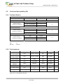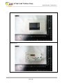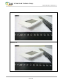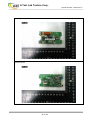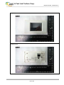
1
A Test Lab Techno Corp.
Report Number: 1402CE13-01
EMC Test Report
Product Type
Applicant
Address
Trade Name
Model Number
Test
Specification
:
:
:
:
:
:
Receive Date
Test Period
Issue Date
: Jan. 29, 2014
: Feb. 05 ~ Feb. 10, 2014
: Feb. 17, 2014
ICP DAS I-7 Series I/O Converter
ICP DAS CO., LTD.
No. 111, Kuangfu N. Rd., Hukon Shiang, Hsinchu, Taiwan 303, R.O.C
ICP DAS
I-7520A
EN 55022: 2010 +AC:2011 / Class A
EN 55024: 2010
EN 61000-3-2: 2006 +A1:2009 + A2: 2009 / Class A
EN 61000-3-3: 2008
EN 61000-4-2:2009
EN 61000-4-3:2006 +A1:2008 +A2:2010
EN 61000-4-4:2012
EN 61000-4-5:2006
EN 61000-4-6:2009
EN 61000-4-8:2010
EN 61000-4-11:2004
Issue by
A Test Lab Techno Corp.
No. 140-1, Changan Street, Bade City,
Taoyuan County 334, Taiwan R.O.C.
Tel:+886-3-2710188 / Fax:+886-3-2710190
Taiwan Accreditation Foundation accreditation number: 1330
Note: This report shall not be reproduced except in full, without the written approval of A Test Lab Techno
Corp. This document may be altered or revised by A Test Lab Techno Corp. personnel only, and shall be
noted in the revision section of the document. The client should not use it to claim product endorsement by
TAF, or any government agencies. The test results in the report only apply to the tested sample.
1 of 153
A Test Lab Techno Corp.
Report Number: 1402CE13-01
Revision History
Rev.
Issue Date
Revisions
00
Feb. 13, 2014
Initial Issue
01
Feb. 17, 2014
Revised report information.
2 of 153
Revised By
Nina.Lin
A Test Lab Techno Corp.
Report Number: 1402CE13-01
Ver i f i c a t i o n o f C o m p l i a n c e
Issued Date: 02/17/2014
ICP DAS I-7 Series I/O Converter
ICP DAS CO., LTD.
Product Type
Applicant
Address
:
:
:
Trade Name
Model Number
EUT Rated Voltage
Test Voltage
:
:
:
:
Applicable
:
EN 55022:2010 +AC:2011 / Class A
EN 55024:2010
EN 61000-3-2:2006+A1:2009+A2:2009 / Class A
EN 61000-3-3:2008
EN 61000-4-2:2009
EN 61000-4-3:2006 +A1:2008 +A2:2010
EN 61000-4-4:2012
EN 61000-4-5:2006
EN 61000-4-6:2009
EN 61000-4-8:2010
EN 61000-4-11:2004
Test Result
:
Complied
Performing Lab.
:
A Test Lab Techno Corp.
No. 140-1, Changan Street, Bade City,
Taoyuan County 334, Taiwan R.O.C.
Tel:+886-3-2710188 / Fax:+886-3-2710190
Taiwan Accreditation Foundation accreditation number: 1330
http://www.atl-lab.com.tw/e-index.htm
Standard
No. 111, Kuangfu N. Rd., Hukon Shiang, Hsinchu, Taiwan 303,
R.O.C
ICP DAS
I-7520A
AC 100-250V, 50-60Hz, 2.0A
230 Vac / 50 Hz
The above equipment has been tested by A Test Lab Techno Corp., and found compliance with the requirements
set forth in the Electromagnetic Compatibility Directive 2004/108/EC and technical standards mentioned above. The
results of testing in this report apply only to the product/system, which was tested. Other similar equipment will not
necessarily produce the same results due to production tolerance and measurement uncertainties.
Approved By
(Manager)
:
Reviewed By
(Cran Yang)
(Testing Engineer)
3 of 153
:
(Frank Lin)
A Test Lab Techno Corp.
Report Number: 1402CE13-01
TABLE OF CONTENTS
1 General Information .........................................................................................................5
2 EUT Description................................................................................................................8
3 Test Methodology...........................................................................................................13
3.1. Decision of Test Mode ...........................................................................................13
3.2. EUT Exercise Software..........................................................................................13
3.3. Configuration of Test System Details .....................................................................14
3.4. Test Site Environment............................................................................................16
4 Emission Test .................................................................................................................17
4.1. Conducted Emission Measurement .......................................................................17
4.2. Radiated Interference Measurement .....................................................................25
4.3. Harmonics Current Measurement..........................................................................34
4.4. Voltage Fluctuation and Flicker..............................................................................39
5 Immunity Test .................................................................................................................43
5.1. Electrostatic Discharge (ESD) ...............................................................................43
5.2. Radiated Electromagnetic Field (RS).....................................................................50
5.3. Electrical Fast Transient/Burst (EFT) .....................................................................54
5.4. Surge .....................................................................................................................57
5.5. Conducted Susceptibility (CS) ...............................................................................61
5.6. Power Frequency Magnetic Field (PMF) ...............................................................65
5.7. Voltage Dips and Interruption.................................................................................68
6 EUT Photograph .............................................................................................................72
4 of 153
A Test Lab Techno Corp.
Report Number: 1402CE13-01
1
General Information
1.1.
Summary of Test Result
Emission
Standard
Item
Result
Remark
EN 55022:2010 +AC:2011
Conducted Emission
PASS
Meet Class A limit
EN 55022: 2010+AC:2011
Radiated Emission
PASS
Meet Class A limit
EN 61000-3-2: 2006 +A1:2009
+ A2: 2009
Harmonic current emissions
PASS
Meet Class A limit
EN 61000-3-3: 2008
Voltage fluctuations & flicker
PASS
Meets the requirements
Immunity
Standard
EN 61000-4-2:2009
Item
Result
Remark
ESD
PASS
Meets the requirements of Criterion B
EN 61000-4-3:2006 +A1:2008
+A2:2010
RS
PASS
Meets the requirements of Criterion A
EN 61000-4-4:2012
EFT
PASS
Meets the requirements of Criterion B
EN 61000-4-5:2006
Surge
PASS
Meets the requirements of Criterion B
EN 61000-4-6:2009
CS
PASS
Meets the requirements of Criterion A
EN 61000-4-8:2010
PMF
PASS
Meets the requirements of Criterion A
EN 61000-4-11:2004
Voltage
dips &
voltage
variations
PASS
Meets the requirements of
Voltage Dips:
1) >95% reduction Criterion B
2)
30% reduction Criterion C
Voltage Interruptions:
1) >95% reduction Criterion C
The test results of this report relate only to the tested sample(s) identified in this report. Manufacturer or
whom it may concern should recognize the pass or fail of the test result.
5 of 153
A Test Lab Techno Corp.
Report Number: 1402CE13-01
1.2.
Measurement Uncertainty
Conducted Emission
The measurement uncertainty is evaluated as ± 2.02 dB.
Conducted Emissions (Telecommunication Ports)
The measurement uncertainty is evaluated as ± 2.02 dB.
Radiated Emission
The Vertical measurement uncertainty of 30MHz - 1GHz is evaluated as ± 3.62 dB.
The Horizontal measurement uncertainty of 30MHz - 1GHz is evaluated as ± 3.98 dB.
The Vertical measurement uncertainty of 1GHz - 6GHz is evaluated as ± 3.07 dB.
The Horizontal measurement uncertainty of 1GHz - 6GHz is evaluated as ± 3.11 dB.
Harmonic Current Emission
The measurement uncertainty is evaluated as ± 1.2 %.
Voltage Fluctuations and Flicker
The measurement uncertainty is evaluated as ± 1.5 %.
Electrostatic Discharge
As what is concluded in the document from Note2 of clause 5.4.6.2 of ISO/IEC 17025: 2005[E], the
requirements for measurement uncertainty in ESD testing are deemed to have been satisfied, and the
testing is reported in accordance with the relevant ESD standards. The immunity test signal from the ESD
system meet the required specifications in IEC 61000-4-2 through the calibration report with the calibrated
uncertainty for the waveform of voltage and timing as being 1.52 % and 2.69%.
Radiated susceptibility
As what is concluded in the document from Note2 of clause 5.4.6.2 of ISO/IEC 17025: 2005[E], the
requirements for measurement uncertainty in RS testing are deemed to have been satisfied, and the testing
is reported in accordance with the relevant RS standards. The immunity test signal from the RS system
meet the required specifications in IEC 61000-4-3 through the calibration for the uniform field strength and
monitoring for the test level with the uncertainty evaluation report for the electrical filed strength as being
2.65 dB.
Electrical fast transient/burst
As what is concluded in the document from Note2 of clause 5.4.6.2 of ISO/IEC 17025: 1999[2], the
requirements for measurement uncertainty in EFT/Burst testing are deemed to have been satisfied, and the
testing is reported in accordance with the relevant FT/Burst standards. The immunity test signal from the
FT/Burst system meet the required specifications in IEC 61000-4-4 through the calibration report with the
calibrated uncertainty for the waveform of voltage. Frequency and timing as being 1.57% and 2.73%.
6 of 153
A Test Lab Techno Corp.
Report Number: 1402CE13-01
Surge
As what is concluded in the document from Note2 of clause 5.4.6.2 of ISO/IEC 17025: 2005[E], the
requirements for measurement uncertainty in Surge testing are deemed to have been satisfied, and the
testing is reported in accordance with the relevant Surge standards. The immunity test signal from the Surge
system meet the required specifications in IEC 61000-4-5 through the calibration report with the calibrated
uncertainty for the waveform of voltage and timing as being 1.58 % and 2.71%.
Conducted susceptibility
As what is concluded in the document from Note2 of clause 5.4.6.2 of ISO/IEC 17025: 2005[E], the
requirements for measurement uncertainty in CS testing are deemed to have been satisfied, and the testing
is reported in accordance with the relevant CS standards. The immunity test signal from the CS system
meet the required specifications in IEC 61000-4-6 through the calibration for unmodulated signal and
monitoring for the test level with the uncertainty evaluation report for the injected modulated signal level
through CDN and EM Clamp/Direct Injection as being 3.68 dB and 2.72 dB.
Power frequency magnetic field
As what is concluded in the document from Note2 of clause 5.4.6.2 of ISO/IEC 17025: 2005[E], the
requirements for measurement uncertainty in PFM testing are deemed to have been satisfied, and the
testing is reported in accordance with the relevant PFM standards. The immunity test signal from the PFM
system meet the required specifications in IEC 61000-4-8 through the calibration report with the calibrated
uncertainty for the Gauss Meter to verify the output level of magnetic field strength as being 1.8 %.
Voltage dips and interruption
As what is concluded in the document from Note2 of clause 5.4.6.2 of ISO/IEC 17025: 2005[E], the
requirements for measurement uncertainty in DIP testing are deemed to have been satisfied, and the testing
is reported in accordance with the relevant DIP standards. The immunity test signal from the DIP system
meet the required specifications in IEC 61000-4-11 through the calibration report with the calibrated
uncertainty for the waveform of voltage and timing as being 1.58 % and 2.72%.
7 of 153
A Test Lab Techno Corp.
Report Number: 1402CE13-01
2
EUT Description
Product Type
:
ICP DAS
Trade Name
:
ICP DAS
Model Number
:
I-7520A
Applicant
:
ICP DAS CO., LTD.
No. 111, Kuangfu N. Rd., Hukon Shiang, Hsinchu, Taiwan 303, R.O.C
Manufacturer
:
ICP DAS CO., LTD.
No. 111, Kuangfu N. Rd., Hukon Shiang, Hsinchu, Taiwan 303, R.O.C
I-7 Series I/O Converter
I/O Port Description:
I/O Port Types
Q’TY
Test Description
1). LAN Port
1
Connected to PC
2). RS-232 Port
1
Connected to PC
3). USB Port
1
Connected to PC
4). AC Power Port
1
Connected to AC input
5). Signal Port
2
Connected to EUT
8 of 153
A Test Lab Techno Corp.
Report Number: 1402CE13-01
Feature of Equipment under Test:
The model listed below is series model to I-7520A.
Main
Software
Diversity
Mode 1
I-7520
---
Isolated RS-232 to RS-485 Converter
I-7520A
---
IsolIsolated RS-232 to RS-422/485 Converter
I-7520R
---
RS-232 to Isolated RS-485 Converter
I-7520AR
---
RS-232 to Isolated RS-422/485 Converter
I-7510
---
Isolated RS-485 Repeater
I-7510A
---
Isolated RS-422/485 Repeater/Converter
V
I-7510AR
---
Three Way Isolated RS-422/485 Repeater/Converter
V
I-7561
---
USB to Isolated RS-485 Converter
V
I-7513
---
Three Way Isolated RS-485 Active Star Wiring Hub
V
I-7514U
---
Isolated 4 Channels RS-485 Repeater/Hub/Splitter
V
I-7018
---
8-channel Analog Input Module
V
I-7017
---
8-channel Analog Input Module with DCON Protocol
M-7017
---
I-7017F
---
TPD-280
---
2.8" Touch HMI device with RS-485
V
TPD-283
---
2.8" Touch HMI device with Ethernet (PoE)
V
TPD-283-BK
---
2.8"Touch HMI device with Ethernet
M-7055
---
8-channel Isolated Digital Input and 8-channel Isolated Digital
Output Module
M-7055D
---
M-7055 with LED Display
I-7055
---
8-channel Isolated Digital Input and 8-channel Isolated Digital
Output Module with DCON Protocol
I-7055D
---
I-7055 with LED Display
M-7055-NPN
---
8-channel Isolated Digital Input and 8-channel Isolated Digital
Output Module with DCON and Modbus Protocols
M-7055D-NPN
---
M-7055-NPN with LED Display
I-7055-NPN
---
8-channel Isolated Digital Input and 8-channel Isolated Digital
Output Module with DCON and Modbus Protocols
I-7055D-NPN
---
I-7055-NPN with LED Display
I-7051
---
16-channel Isolated Digital Input Module with DCON Protocol
I-7051D
---
I-7051 with LED Display
M-7051
---
16-channel Isolated Digital Input Module with DCON and
Modbus Protocols
M-7051D
---
M-7051 with LED Display
8-channel Analog Input Module with DCON and Modbus RTU
Protocols
8-channel Analog Input Module with DCON Protocol (Fast
Sampling Version)
9 of 153
V
V
V
V
V
V
A Test Lab Techno Corp.
Report Number: 1402CE13-01
Main
Software
Diversity
I-7551
---
Isolated RS-232 to RS-232 Converter
I-7045
---
16-channel Isolated Digital Output Module with DCON Protocol
I-7045D
---
I-7045 with LED Display
M-7045
---
16-channel Isolated Digital Output Module with DCON and
Modbus Protocols
M-7045D
---
M-7045-G with LED Display
I-7045-NPN
---
16-channel Isolated Digital Output Module with DCON Protocol
I-7045D-NPN
---
I-7045-NPN-G with LED Display
M-7045-NPN
---
16-channel Isolated Digital Output Module with DCON and
Modbus Protocols
M-7045D-NPN
---
M-7045-NPN-G with LED Display
I-7052
---
8-channel Isolated Digital Input Module with 16-bit Counters
I-7052D
---
I-7052D with LED Display
M-7052
---
8-channel Isolated Digital Input Module with DCON and
Modbus Protocols
M-7052D
---
M-7052 with LED Display
I-7065
---
4-channel Isolated Digital Input and 5-channel Relay Output
Module using the DCON Protocol
I-7065D
---
I-7065 with LED Display
M-7065
---
4-channel Isolated Digital Input and 5-channel Relay Output
Module using the DCON and Modbus Protocols
M-7065D
---
M-7065-G with LED Display
I-7017C
---
8-channel Current Input Module using the DCON Protocol
M-7017C
---
I-7017FC
---
I-7017RC
---
M-7017RC
---
I-7067
---
7-channel Relay Output Module
I-7067D
---
I-7067D with LED Display
I-7043
---
16-channel Non-isolated Digital Output Module using the
DCON Protocol
I-7043D
---
I-7043 with LED Display
I-7024
---
4-channel Analog Output Module with DCON Protocol
I-7024R
---
4-channel Analog Output and 5-channel DI Module with DCON
Protocol
8-channel Current Input Module using the DCON and Modbus
Protocol
8-channel Current Input Module using the DCON Protocol (fast
sampling version)
8-channel Analog Input Module using the DCON Protocol with
High Voltage Protection
8-channel Analog Input Module using the DCON and Modbus
RTU Protocol with High Voltage Protection
10 of 153
Mode 1
V
V
V
V
V
V
V
V
V
V
A Test Lab Techno Corp.
Report Number: 1402CE13-01
Main
Software
Diversity
4-channel Analog Output Module with DCON and Modbus
Protocol
4-channel Analog Output and 5-channel DI Module with DCON
and Modbus Protocol
8-channel Thermistor Input and 6 channel Alarm Output
Module
Mode 1
M-7024
---
M-7024R
---
M-7005
---
I-7018R
---
8-channel Analog Input Module with High Voltage Protection
V
I-7017R
---
8-channel Analog Input Module using the DCON Protocol
V
M-7017R
---
8-channel Analog Input Module using the DCON and Modbus
RTU Protocol
I-7017R-A5
---
8-channel Analog Input Module using the DCON Protocol
M-7017R-A5
---
8-channel Analog Input Module using the DCON and Modbus
RTU Protocol
NS-208A
---
Unmanaged 8-port Industrial 10/100 Mbps Ethernet Switch
NSM-208A
---
I-2533CS-A
---
I-2533CS-B
---
NS-105PSE-24V
---
NS-205PSE-24V
---
NSM-205PSE-24V
---
tDS-712
---
Tiny Device Server with PoE and 1 RS-232 Port
tGW-712
---
Tiny Modbus/TCP to RTU/ASCII gateway with PoE and 1
RS-232 Port
tDS-722
---
Tiny Device Server with PoE and 2 RS-232 Ports
tDS-732
---
Tiny Device Server with PoE and 3 RS-232 Ports
tGW-722
---
tGW-732
---
tDS-715
---
Tiny Device Server with PoE and 1 RS-422/485 Port
tDS-718
---
Tiny Device Server with PoE and 1 RS-232/422/485 Port
tGW-718
---
tGW-715
---
GW-7472
---
Unmanaged 8-port Industrial 10/100 Mbps Ethernet Switch
with Metal Casing
CAN to Single Mode Fiber Bridge ; 1 (15 Km) single mode, SC
connector, TX 1310 nm, RX 1550 nm
CAN to Single Mode Fiber Bridge ; 1 (15 Km) single mode, SC
connector, TX 1550 nm, RX 1310 nm
Unmanaged 5-port 10/100 Mbps PoE (PSE) Ethernet Switch;
+24 VDC Input
Unmanaged 5-port 10/100 Mbps PoE (PSE) Ethernet Switch;
+24 VDC Input
Unmanaged 5-port 10/100 Mbps PoE (PSE) Ethernet Switch
with Metal Casing; +24 VDC Input
V
V
V
V
V
V
V
Tiny Modbus/TCP to RTU/ASCII gateway with PoE and 2
RS-232 Ports
Tiny Modbus/TCP to RTU/ASCII gateway with PoE and 3
RS-232 Ports
Tiny Modbus/TCP to RTU/ASCII gateway with PoE and 1
RS-232/422/485 Port
Tiny Modbus/TCP to RTU/ASCII gateway with PoE and 1
RS-422/485
Tiny EtherNet/IP to Modbus RTU/TCP gateway with PoE and 1
RS-422/485
11 of 153
V
A Test Lab Techno Corp.
Report Number: 1402CE13-01
Main
Software
Diversity
Mode 1
NS-200PS
---
Industrial PoE Splitter
V
ET-7065
---
Ethernet I/O Module with 6-ch PhotoMOS Relay, 6-ch DI
V
PPDS-743-MTCP
---
Programmable Device Server with PoE, Modbus Gateway, 3
RS-232 ports and 1 RS-485 port (RoHS) Includes One
CA-0910 Cable
PPDSM-743-MTCP
---
PPDS-743-MTCP CR with Metal Case
PPDS-743D-MTCP
---
Programmable Device Server with PoE, Modbus Gateway, 3
RS-232 ports, 1 RS-485 port and an LED Display (RoHS)
Includes One CA-0910 Cable
PPDSM-743D-MTCP
---
PPDS-743D-MTCP CR with Metal Case
I-7188E3
---
I-7188E3D without LED display
I-7188E3D
---
I-7188E2
---
I-7188E2-MTCP
---
I-7188E2D with default Modbus/TCP firmware
I-7188E2D
---
I-7188E2D without LED display
X110
---
14-channel D/I
Internet communication controller with one RS-232, one
RS-485 ,one RS-422/RS-485 ,DI/O and one Ethernet
Internet communication controller with one RS-232, one
RS-485 and one Ethernet
12 of 153
V
V
V
V
A Test Lab Techno Corp.
Report Number: 1402CE13-01
3
Test Methodology
3.1.
Decision of Test Mode
The following test mode(s) were scanned during the preliminary test:
Pre-Test Mode
Mode 1: Normal Operation Mode
After the preliminary scan, the following test mode was found to produce the highest emission
level.
Final Test Mode
Emission
Immunity
Conducted Emission
Mode 1
Radiated Emission
Mode 1
Harmonic current emissions
Mode 1
Voltage fluctuations & flicker
Mode 1
ESD
Mode 1
RS
Mode 1
EFT
Mode 1
Surge
Mode 1
CS
Mode 1
PMF
Mode 1
Voltage dips & voltage variations
Mode 1
Then, the above highest emission mode of the configuration of the EUT and cable was chosen for all
final test items.
3.2.
EUT Exercise Software
1.
Setup the EUT and simulators as shown on 3.3.
2.
Turn on the power of all equipment.
3.
The EUT will start to operate function.
13 of 153
A Test Lab Techno Corp.
Report Number: 1402CE13-01
3.3.
Configuration of Test System
Mode 1
A
E
AC Input
F
I
B
D
C
(1)
Monitor
EUT
PC
EUT
G
(2)
(3)
Keyboard
Mouse
Signal Cable Type
H
Signal Cable Description
A
LAN Cable
Shielded, 1.8m with one core
B
AC Power Cable
Non-Shielded, 1.7m with one core
C
DC Power Cable
Non-Shielded, 0.5m
D
RS-232 Cable
Non-Shielded, 0.5m with one core
E
RS-232 Cable
Shielded, 1.7m with two cores
F
USB Cable
Shielded, 1.7m with two cores
G
P/S 2 Cable
Shielded, 1.8m
H
P/S 2 Cable
Shielded, 1.8m
I
O-Sub Cable
Shielded, 1.8m with two cores
14 of 153
A Test Lab Techno Corp.
Report Number: 1402CE13-01
Devices Description
Product
Manufacturer
Model Number
Serial Number
Power Cord
(1)
Monitor
DELL
U2711
CN0H530T7426105K04
3L
Non-Shielded, 1.8m
(2)
Keyboard
HP
SK-2880
BC3520FJ6X5310
Power by PC
(3)
Mouse
DELL
MOC5UO
HOX06NVO
Power by PC
(4)
PC
ICP DAS
VB-115H
N/A
Non-Shielded, 1.7m
Diversity
Mode 1
※ PC Keypart information
Main
Software
Universal PCI, Serial Communication Board with 4
RS-422/485 ports (RoHS). Includes One CA-4002
Connector
8-channel Relay Output & 8-channel Isolated Digital
Input Board
Includes one CA-4002 D-Sub connector.
12-channel Timer/Counter Board Includes one
CA-4002 D-Sub connector.
(4)-1 VXC-144U
---
(4)-2 PISO-725
---
(4)-3 PCI-TMC12A
---
(4)-4 DIO-144
---
144-channel Digital I/O Board
(4)-5 DIO-96
---
96-channel Digital I/O Board
V
V
V
V
Support Unit
Product
1.
Industrial Power
Supply
Manufacturer
Model Number
Serial Number
Power Cord
ICP DAS
DP-1200
N/A
Non-Shielded, 1.7m
with one core
15 of 153
A Test Lab Techno Corp.
Report Number: 1402CE13-01
3.4.
Test Site Environment
Items
Test Item
Temperature (°C)
Required (IEC 60068-1)
Actual
15-35
26.0
25-75
60.0
860-1060
950
15-35
26.0
25-75
60.0
860-1060
950
--
26.0
--
60.0
Barometric pressure (mbar)
--
950
Temperature (°C)
--
26.0
--
60.0
--
950
15-35
24.0
30-60
43.6
860-1060
950
--
20.1
--
54.2
--
950
15-35
22.3
30-60
54.8
860-1060
950
15-35
24.0
10-75
52.1
860-1060
950
--
24.0
--
52.1
--
950
15-35
22.6
25-75
51.6
860-1060
950
15-35
19.1
25-75
54.6
860-1060
950
Humidity (%RH)
EN 55022 CE
Barometric pressure (mbar)
Temperature (°C)
Humidity (%RH)
EN 55022 RE
Barometric pressure (mbar)
Temperature (°C)
Humidity (%RH)
Humidity (%RH)
EN 61000-3-2
EN 61000-3-3
Barometric pressure (mbar)
Temperature (°C)
Humidity (%RH)
EN 61000-4-2
Barometric pressure (mbar)
Temperature (°C)
Humidity (%RH)
EN 61000-4-3
Barometric pressure (mbar)
Temperature (°C)
Humidity (%RH)
EN 61000-4-4
Barometric pressure (mbar)
Temperature (°C)
Humidity (%RH)
EN 61000-4-5
Barometric pressure (mbar)
Temperature (°C)
Humidity (%RH)
EN 61000-4-6
Barometric pressure (mbar)
Temperature (°C)
Humidity (%RH)
EN 61000-4-8
Barometric pressure (mbar)
Temperature (°C)
Humidity (%RH)
EN 61000-4-11
Barometric pressure (mbar)
16 of 153
A Test Lab Techno Corp.
Report Number: 1402CE13-01
4
Emission Test
4.1.
Conducted Emission Measurement
4.1.1. Limit
A.C. Mains Conducted Interference Limit:
Class A Equipment
(dBuV)
Frequency
(MHz)
Note:
Class B Equipment
(dBuV)
Quasi-peak
Average
Quasi-peak
Average
0.15 - 0.5
79
66
66 - 56
56 - 46
0.50 - 5.0
73
60
56
46
5.0 - 30.0
73
60
60
50
(1) The lower limit shall apply at the transition frequencies.
(2) The limit decreases in line with the logarithm of the frequency in the range 0.15 to 0.50 MHz.
Telecommunication Port Conducted Interference Limits:
Class A Equipment
Requirement
(MHz)
Voltage Limit
(dBμV)
Class B Equipment
Current Limit
(dBμA)
Voltage Limit
(dBμV)
Current Limit
(dBμA)
QP
Avg.
QP
Avg.
QP
Avg.
QP
Avg.
0.15 to 0.50
97 to 87
84 to 74
53 to 43
40 to 30
84 to 74
74 to 64
40 to 30
30 to 20
0.50 to 30
87
74
43
30
74
64
30
20
4.1.2. Test Instruments
Equipment
Manufacturer
Model Number
Serial Number
Cal. Date
Remark
Test Receiver
R&S
ESCI
100367
06/06/2013
(1)
LISN
R&S
ENV216
101040
03/04/2013
(1)
LISN
R&S
ENV216
101041
03/04/2013
(1)
T-LISN
FCC
FCC-TLISN-T2-02
20574
04/19/2013
(1)
T-LISN
FCC
FCC-TLISN-T4-02
20529
04/19/2013
(1)
T-LISN
TESQ
ISN-T8
34413
04/25/2013
(1)
Test Site
ATL
TE02
TE02
N.C.R.
-----
Remark:
(1)
Calibration period 1 year.
(2)
Calibration period 2 years.
NOTE: N.C.R. = No Calibration Request.
17 of 153
A Test Lab Techno Corp.
Report Number: 1402CE13-01
4.1.3. Test Setup
A.C. Mains Setup
Telecommunication Port Setup
18 of 153
A Test Lab Techno Corp.
Report Number: 1402CE13-01
4.1.4. Test Procedure
The EUT and simulators are connected to the main power through a line impedance stabilization
network (L.I.S.N.). This provides a 50 ohm /50uH coupling impedance for the measuring equipment.
The peripheral devices are also connected to the main power through a LISN that provides a
50ohm/50uH coupling impedance with 50ohm termination.
The mains voltage shall be supplied to the EUT via the LISN when the measurement of
telecommunication port is performed. The common mode disturbances at the telecommunication port
shall be connected to the ISN.
For A.C. mains conducted interference, measured both sides of A.C. lines and carried out using
quasi-peak and average detector receivers of maximum conducted interference.
For telecommunication port interference measurement, using ISNs with suitable longitudinal conversion
losses (LCL) as defined in the port of specification from manufacture, and the LCL shall be meet the
related standard requirement. Measured the line and carried out using quasi-peak and average detector
receivers of maximum conducted interference.
Conducted emissions were invested over the frequency range from 0.15 MHz to 30 MHz using a
receiver bandwidth of 9 kHz. The equipment under test (EUT) shall be meet the limits in section 4.1.2,
as applicable, including the average limit and the quasi-peak limit when using respectively (A.C. mains
and telecommunication port), an average detector and quasi-peak detector measured in accordance
with the methods described of related standard. Either the voltage limits or the current limits shall be met.
If the average limit is met when using a quasi-peak detector receiver, the EUT shall be deemed to meet
both limits and measurement with the average detector receiver is unnecessary.
If the reading of the measuring receiver shows fluctuations close to the limit, the reading shall be
observed for at least 15 s at each measurement frequency; the higher reading shall be recorded with
the exception of any brief isolated high reading which shall be ignored.
19 of 153
A Test Lab Techno Corp.
Report Number: 1402CE13-01
4.1.5. Test Result
Standard:
EN 55022 Class A
Line:
L1
Test item:
Conducted Emission
Power:
AC 230V/50Hz
Model Number:
I-7520A
Temp.(℃)/Hum.(%RH):
26(℃)/60%RH
Mode:
Mode 1
Date:
2014/02/05
Test By:
Frank Lin
Description:
No.
Frequency
QP
AVG
Correction
QP
AVG
QP
AVG
QP
AVG
reading
reading
factor
result
result
limit
limit
margin
margin
(MHz)
(dBuV)
(dBuV)
(dB)
(dBuV)
(dBuV)
(dBuV)
(dBuV)
(dB)
(dB)
1
0.1500
52.46
20.79
9.62
62.08
30.41
79.00
66.00
-16.92
-35.59
Pass
2
0.1740
49.47
17.66
9.62
59.09
27.28
79.00
66.00
-19.91
-38.72
Pass
3
0.2020
46.61
15.23
9.62
56.23
24.85
79.00
66.00
-22.77
-41.15
Pass
4
0.2300
44.17
13.24
9.62
53.79
22.86
79.00
66.00
-25.21
-43.14
Pass
5
0.2580
42.10
11.16
9.62
51.72
20.78
79.00
66.00
-27.28
-45.22
Pass
6
2.1780
31.86
31.81
9.70
41.56
41.51
73.00
60.00
-31.44
-18.49
Pass
7
9.8020
26.51
24.69
10.09
36.60
34.78
73.00
60.00
-36.40
-25.22
Pass
8
21.0540
24.69
18.96
9.78
34.47
28.74
73.00
60.00
-38.53
-31.26
Pass
Note: 1. Result (dBuV) = Correction factor (dB) + Reading(dBuV).
2. Correction factor (dB) = Cable loss (dB) + L.I.S.N. factor (dB).
20 of 153
Remark
A Test Lab Techno Corp.
Report Number: 1402CE13-01
Standard:
EN 55022 Class A
Line:
N
Test item:
Conducted Emission
Power:
AC 230V/50Hz
Model Number:
I-7520A
Temp.(℃)/Hum.(%RH):
26(℃)/60%RH
Mode:
Mode 1
Date:
2014/02/05
Test By:
Frank Lin
Description:
No.
Frequency
QP
AVG
Correction
QP
AVG
QP
AVG
QP
AVG
reading
reading
factor
result
result
limit
limit
margin
margin
(MHz)
(dBuV)
(dBuV)
(dB)
(dBuV)
(dBuV)
(dBuV)
(dBuV)
(dB)
(dB)
1
0.1500
52.51
20.84
9.63
62.14
30.47
79.00
66.00
-16.86
-35.53
Pass
2
0.1620
50.91
19.05
9.63
60.54
28.68
79.00
66.00
-18.46
-37.32
Pass
3
0.1860
48.21
16.64
9.63
57.84
26.27
79.00
66.00
-21.16
-39.73
Pass
4
0.2180
45.26
13.89
9.63
54.89
23.52
79.00
66.00
-24.11
-42.48
Pass
5
0.2460
43.05
29.53
9.63
52.68
39.16
79.00
66.00
-26.32
-26.84
Pass
6
0.3580
36.60
8.69
9.63
46.23
18.32
79.00
66.00
-32.77
-47.68
Pass
7
2.1780
30.91
30.75
9.70
40.61
40.45
73.00
60.00
-32.39
-19.55
Pass
8
10.1620
26.57
24.34
10.10
36.67
34.44
73.00
60.00
-36.33
-25.56
Pass
9
19.7140
26.35
23.76
9.85
36.20
33.61
73.00
60.00
-36.80
-26.39
Pass
Note: 1. Result (dBuV) = Correction factor (dB) + Reading(dBuV).
2. Correction factor (dB) = Cable loss (dB) + L.I.S.N. factor (dB).
21 of 153
Remark
A Test Lab Techno Corp.
Report Number: 1402CE13-01
Standard:
EN 55022 Class A
Line:
N/A
Test item:
Conducted Emission
Power:
AC 230V/50Hz
Model Number:
I-7520A
Temp.(℃)/Hum.(%RH):
26(℃)/60%RH
Mode:
Mode 1 (ISN 10M)
Date:
2014/02/05
Test By:
Frank Lin
Description:
No.
Frequency
QP
AVG
Correction
QP
AVG
QP
AVG
QP
AVG
reading
reading
factor
result
result
limit
limit
margin
margin
(MHz)
(dBuV)
(dBuV)
(dB)
(dBuV)
(dBuV)
(dBuV)
(dBuV)
(dB)
(dB)
1
0.2420
49.03
48.28
9.97
59.00
58.25
93.03
80.03
-34.03
-21.78
Pass
2
1.0900
57.05
56.58
9.71
66.76
66.29
87.00
74.00
-20.24
-7.71
Pass
3
1.3300
59.14
58.28
9.71
68.85
67.99
87.00
74.00
-18.15
-6.01
Pass
4
1.8140
60.44
59.47
9.69
70.13
69.16
87.00
74.00
-16.87
-4.84
Pass
5
4.1100
56.04
55.24
9.61
65.65
64.85
87.00
74.00
-21.35
-9.15
Pass
6
9.4300
49.93
48.96
9.95
59.88
58.91
87.00
74.00
-27.12
-15.09
Pass
7
14.2660
37.51
33.43
9.66
47.17
43.09
87.00
74.00
-39.83
-30.91
Pass
Note: 1. Result (dBuV) = Correction factor (dB) + Reading(dBuV).
2. Correction factor (dB) = Cable loss (dB) + L.I.S.N. factor (dB).
22 of 153
Remark
A Test Lab Techno Corp.
Report Number: 1402CE13-01
Standard:
EN 55022 Class A
Line:
N/A
Test item:
Conducted Emission
Power:
AC 230V/50Hz
Model Number:
I-7520A
Temp.(℃)/Hum.(%RH):
26(℃)/60%RH
Mode:
Mode 1 (ISN 100M)
Date:
2014/02/05
Test By:
Frank Lin
Description:
No.
Frequency
QP
AVG
Correction
QP
AVG
QP
AVG
QP
AVG
reading
reading
factor
result
result
limit
limit
margin
margin
(MHz)
(dBuV)
(dBuV)
(dB)
(dBuV)
(dBuV)
(dBuV)
(dBuV)
(dB)
(dB)
1
0.2420
49.51
48.50
9.97
59.48
58.47
93.03
80.03
-33.55
-21.56
Pass
2
1.0900
56.69
56.19
9.71
66.40
65.90
87.00
74.00
-20.60
-8.10
Pass
3
1.3300
59.12
58.24
9.71
68.83
67.95
87.00
74.00
-18.17
-6.05
Pass
4
1.8140
60.16
60.11
9.69
69.85
69.80
87.00
74.00
-17.15
-4.20
Pass
5
4.2300
56.23
55.54
9.61
65.84
65.15
87.00
74.00
-21.16
-8.85
Pass
6
9.5460
50.20
48.20
9.95
60.15
58.15
87.00
74.00
-26.85
-15.85
Pass
Note: 1. Result (dBuV) = Correction factor (dB) + Reading(dBuV).
2. Correction factor (dB) = Cable loss (dB) + L.I.S.N. factor (dB).
23 of 153
Remark
A Test Lab Techno Corp.
Report Number: 1402CE13-01
4.1.6. Test Photograph
Test Mode:
Mode 1
Description:
Front View of Conducted Test
Test Mode:
Mode 1
Description:
Back View of Conducted Test
24 of 153
A Test Lab Techno Corp.
Report Number: 1402CE13-01
4.2.
Radiated Interference Measurement
4.2.1. Limit
dBuV/m (Distance 10m)
Frequency
(MHz)
Class A
Class B
30 ~ 230
40
30
230 ~ 1000
47
37
NOTE: The lower limit shall apply at the transition frequencies.
dBuV/m (Distance 3m)
Frequency
(MHz)
Class A
Class B
Average
Peak
Average
Peak
1000 ~ 3000
56
76
50
70
3000 ~ 6000
60
80
54
74
NOTE: The lower limit shall apply at the transition frequencies.
4.2.2. Test Instruments
10 Meter Chamber
Equipment
Manufacturer
Model Number
Serial Number
Cal. Date
Remark
Pre Amplifier
Agilent
8447D
2944A11120
01/10/2014
(1)
Pre Amplifier
Agilent
8447D
2944A11119
01/10/2014
(1)
Test Receiver
R&S
ESCI
100722
10/26/2013
(1)
Test Receiver
R&S
ESCI
101000
12/03/2013
(1)
VULB 9160
9160-3268
06/05/2013
(1)
VULB 9160
9160-3273
11/29/2013
(1)
TE06
TE06
08/10/2013
(1)
Broadband Antenna
Broadband Antenna
Test Site
SCHWARZBECK
MESS-ELEKTRONIK
SCHWARZBECK
MESS-ELEKTRONIK
ATL
Remark: (1) Calibration period 1 year. (2) Calibration period 2 years.
25 of 153
A Test Lab Techno Corp.
Report Number: 1402CE13-01
3 Meter Chamber
Equipment
Manufacturer
Model Number
Serial Number
Cal. Date
Remark
RF Pre-selector
Agilent
N9039A
MY46520256
01/10/2014
(1)
Spectrum Analyzer
Agilent
E4446A
MY46180578
01/10/2014
(1)
Pre Amplifier
Agilent
8449B
3008A02237
02/22/2013
(1)
Pre Amplifier
Agilent
8447D
2944A10961
02/22/2013
(1)
Horn Antenna
(1~18GHz)
SCHWARZBECK
MESS-ELEKTRONIK
BBHA9120D
9120D-550
06/10/2013
(1)
Test Site
ATL
TE01
888001
08/28/2013
(1)
Remark: (1) Calibration period 1 year. (2) Calibration period 2 years.
4.2.3. Setup
Below 1GHz
26 of 153
A Test Lab Techno Corp.
Report Number: 1402CE13-01
Above 1GHz
4.2.4. Test Procedure
The EUT and its simulators are placed on a turn table which is 0.8 meter above ground. When the EUT
is floor- standing equipment, it is placed on the ground plane which has a 15 cm non-conductive
covering to insulate the EUT from the ground plane.
The turn table can rotate 360 degrees to determine the position of the maximum emission level. The
EUT was positioned such that the distance from antenna to the EUT was 10 meters for under 1GHz,
and 3 meter for above 1GHz if the highest internal source frequency of the EUT is higher than 108 MHz.
The highest internal source of a EUT is defined as the highest frequency generated or used within the
EUT or on which the EUT operates or tunes. If the highest frequency of the internal sources of the EUT
is less than 108 MHz, the measurement shall only be made up to 1 GHz. If the highest frequency of the
internal sources of the EUT is between 108 MHz and 500 MHz, the measurement shall only be made up
to 2 GHz. If the highest frequency of the internal sources of the EUT is between 500 MHz and 1 GHz,
the measurement shall only be made up to 5 GHz. If the highest frequency of the internal sources of the
EUT is above 1 GHz, the measurement shall be made up to 5 times the highest frequency or 6 GHz,
whichever is less.
The antenna can move up and down between 1 meter and 4 meters to find out the maximum emission
level. Both horizontal and vertical polarization of the antenna are set on measurement. In order to find
the maximum emission, all of the interface cables must be manipulated on radiated measurement.
Radiated emissions were invested over the frequency range from 30MHz to1GHz using a receiver
bandwidth of 120 kHz. Radiated was performed at an antenna to EUT distance of 10 meters.
27 of 153
A Test Lab Techno Corp.
Report Number: 1402CE13-01
4.2.5. Test Result
Standard:
EN 55022 Class A
Test Distance:
10m
Test item:
Radiated Emission
Power:
AC 230V/50Hz
Model Number:
I-7520A
Temp.(℃)/Hum.(%RH):
26(℃)/60%RH
Mode:
Mode 1
Date:
2014/02/05
Ant.Polar.:
Horizontal
Test By:
Frank Lin
No.
Frequency
Reading
Correct
Result
Limit
Margin
Height
Degree
(MHz)
(dBuV)
Factor(dB/m)
(dBuV/m)
(dBuV/m)
(dB)
(cm)
(°)
1
44.7433
41.82
-14.82
27.00
40.00
-13.00
400
160
QP
2
100.2286
54.98
-17.68
37.30
40.00
-2.70
400
133
QP
3
167.2368
43.18
-13.38
29.80
40.00
-10.20
400
259
QP
4
259.2338
49.82
-13.32
36.50
47.00
-10.50
300
117
QP
5
593.0497
44.47
-6.07
38.40
47.00
-8.60
200
15
QP
6
925.7563
39.41
-0.31
39.10
47.00
-7.90
100
52
QP
Note: 1. Result (dBuV) = Correction factor (dB) + Reading(dBuV).
2. Correction factor (dB/m) = Antenna Factor (dB/m) + Cable loss (dB) – Pre-Amplifier gain (dB).
28 of 153
Remark
A Test Lab Techno Corp.
Report Number: 1402CE13-01
Standard:
EN 55022 Class A
Test Distance:
10m
Test item:
Radiated Emission
Power:
AC 230V/50Hz
Model Number:
I-7520A
Temp.(℃)/Hum.(%RH):
26(℃)/60%RH
Mode:
Mode 1
Date:
2014/02/05
Ant.Polar.:
Vertical
Test By:
Frank Lin
No.
Frequency
Reading
Correct
Result
Limit
Margin
Height
Degree
(MHz)
(dBuV)
Factor(dB/m)
(dBuV/m)
(dBuV/m)
(dB)
(cm)
(°)
1
44.5868
46.17
-14.37
31.80
40.00
-8.20
100
355
QP
2
100.2286
54.92
-17.12
37.80
40.00
-2.20
200
245
QP
3
167.2368
40.99
-12.59
28.40
40.00
-11.60
100
150
QP
4
258.3264
54.45
-12.55
41.90
47.00
-5.10
100
328
QP
5
593.0497
40.67
-4.67
36.00
47.00
-11.00
300
80
QP
6
903.3094
34.40
1.10
35.50
47.00
-11.50
200
195
QP
Note: 1. Result (dBuV) = Correction factor (dB) + Reading(dBuV).
2. Correction factor (dB/m) = Antenna Factor (dB/m) + Cable loss (dB) – Pre-Amplifier gain (dB).
29 of 153
Remark
A Test Lab Techno Corp.
Report Number: 1402CE13-01
Standard:
EN 55022 Class A
Test Distance:
3m
Test item:
Radiated Emission
Power:
AC 230V/50Hz
Model Number:
I-7520A
Temp.(℃)/Hum.(%RH):
26(℃)/60%RH
Mode:
Mode 1 (1GHz~6GHz)
Date:
2014/02/05
Ant.Polar.:
Horizontal
Test By:
Frank Lin
No.
Frequency
Reading
Correct
Result
Limit
Margin
(MHz)
(dBuV)
Factor(dB/m)
(dBuV/m)
(dBuV/m)
(dB)
1
1355.000
58.10
-1.90
56.20
76.00
-19.80
peak
2
1355.000
51.43
-1.90
49.53
56.00
-6.47
AVG
3
2395.000
40.81
4.27
45.08
76.00
-30.92
peak
4
3095.000
40.56
6.33
46.89
80.00
-33.11
peak
5
3890.000
38.47
8.93
47.40
80.00
-32.60
peak
6
4200.000
37.85
10.14
47.99
80.00
-32.01
peak
7
4655.000
37.86
11.67
49.53
80.00
-30.47
peak
Note: 1. Result (dBuV) = Correction factor (dB) + Reading(dBuV).
2. Correction factor (dB/m) = Antenna Factor (dB/m) + Cable loss (dB) – Pre-Amplifier gain (dB).
30 of 153
Remark
A Test Lab Techno Corp.
Report Number: 1402CE13-01
Standard:
EN 55022 Class A
Test Distance:
3m
Test item:
Radiated Emission
Power:
AC 230V/50Hz
Model Number:
I-7520A
Temp.(℃)/Hum.(%RH):
26(℃)/60%RH
Mode:
Mode 1 (1GHz~6GHz)
Date:
2014/02/05
Ant.Polar.:
Vertical
Test By:
Frank Lin
No.
Frequency
Reading
Correct
Result
Limit
Margin
(MHz)
(dBuV)
Factor(dB/m)
(dBuV/m)
(dBuV/m)
(dB)
1
1355.000
58.60
-1.90
56.70
76.00
-19.30
peak
2
1355.000
47.61
-1.90
45.71
56.00
-10.29
AVG
3
2510.000
39.48
5.04
44.52
76.00
-31.48
peak
4
3105.000
39.66
6.36
46.02
80.00
-33.98
peak
5
3765.000
37.89
8.40
46.29
80.00
-33.71
peak
6
3980.000
37.92
9.30
47.22
80.00
-32.78
peak
7
4750.000
36.70
11.92
48.62
80.00
-31.38
peak
Note: 1. Result (dBuV) = Correction factor (dB) + Reading(dBuV).
2. Correction factor (dB/m) = Antenna Factor (dB/m) + Cable loss (dB) – Pre-Amplifier gain (dB).
31 of 153
Remark
A Test Lab Techno Corp.
Report Number: 1402CE13-01
4.2.6. Test Photograph
Test Mode:
Mode 1
Description:
Front View of Radiated Emission Test _ Below 1GHz
Test Mode:
Mode 1
Description:
Back View of Radiated Emission Test _ Below 1GHz
32 of 153
A Test Lab Techno Corp.
Report Number: 1402CE13-01
Test Mode:
Mode 1
Description:
Front View of Radiated Emission Test _ Above 1GHz
Test Mode:
Mode 1
Description:
Back View of Radiated Emission Test _ Above 1GHz
33 of 153
A Test Lab Techno Corp.
Report Number: 1402CE13-01
4.3.
Harmonics Current Measurement
4.3.1. Limit
Limits of Class A Harmonics Currents
Harmonics Order
Maximum Permissible
harmonic current
Harmonics Order
Maximum Permissible
harmonic
current
n
(A)
n
(A)
3
2.30
2
1.08
5
1.14
4
0.43
7
0.77
6
0.30
9
0.40
8 ≤ n ≤ 40
0.23 * 8/n
11
0.33
Odd harmonics
Even harmonics
13
0.21
15 ≤ n ≤ 39
0.15 * 15/n
Limits of Class B Harmonics Currents
For Class B equipment, the harmonic of the input current shall not exceed the maximum permissible
values given in table which is the limit of Class A multiplied by a factor of 1.5.
Limits of Class C Harmonics Currents
Harmonics Order
Maximum Permissible harmonic current
Expressed as a percentage of the input current at the fundamental frequency
n
(%)
2
2
3
30.λ*
5
10
7
7
9
5
11 ≤ n ≤ 39
(odd harmonics only)
3
*λ is the circuit power factor
Limits of Class D Harmonics Currents
Harmonics Order
Maximum Permissible harmonic
current per watt
Maximum Permissible
harmonic current
n
(mA/W)
(A)
3
3.4
2.30
5
1.9
1.14
7
1.0
0.77
9
0.5
0.40
11
0.35
0.33
11 ≤ n ≤ 39
(odd harmonics only)
3.85/n
See limit of Class A
34 of 153
A Test Lab Techno Corp.
Report Number: 1402CE13-01
4.3.2. Test Instrument
Equipment
Manufacturer
Model Number
Serial Number
Cal. Date
Remark
Power Harmonics
Analyzers
EMC-Partner AG
HAR1000-1P
171
02/07/2014
(2)
Test Site
ATL
TE05
TE05
N.C.R.
-----
Remark: (1) Calibration period 1 year. (2) Calibration period 2 years.
NOTE: N.C.R. = No Calibration Request.
4.3.3. Setup
4.3.4. Test Procedure
The EUT was placed on the top of a wooden table 0.8 meters above the ground and the EUT is supplied
in series with power analyzer from a power source having the same normal voltage and frequency as
the rated supply voltage and the equipment under test. And the rated voltage at the supply voltage of
EUT of 0.94 times and 1.06 times shall be performed.
A definition of the normal load or of the conditions for adequate heat discharge can usually be found in
the EN publication corresponding to the equipment under test.
Equipment may have several separately controlled circuits. Each circuit is considered as a single piece
of equipment if it can be operated independently and separately from the other circuits.
35 of 153
A Test Lab Techno Corp.
Report Number: 1402CE13-01
4.3.5. Test Result
Model Number
I-7520A
Test Item
Power Harmonics
Test Mode
Mode 1
Date of Test
2014/02/07
Test Result: Pass
Test Site
TE05
Source qualification: Normal
Current & voltage waveforms
Harmonics and Class A limit line
European Limits
Note 1:
For the following categories of equipment limits are not specified in this edition of the standard.
-Equipment with a rated power of 75 W or less, other than lighting equipment.
-Professional equipment with a total rated power greater than 1 kW;
-Symmetrically controlled heating elements with a rated power less than or equal to 200 W;
-Independent dimmers for incandescent lamps with a rated power less than or equal to 1 kW.
36 of 153
A Test Lab Techno Corp.
Report Number: 1402CE13-01
Urms =
Irms =
P
=
THDi =
229.7V
0.256A
40.08W
61.0 %
Test - Time :
Freq =
Ipk =
S
=
THDu =
49.987
0.516A
58.77VA
0.10 %
Range:
cf =
pf =
Class A
1A
2.015
0.682
3min ( 100 %)
Test completed, Result: PASSED
Order
1
2
3
4
5
6
7
8
9
10
11
12
13
14
15
16
17
18
19
20
21
22
23
24
25
26
27
28
29
30
31
32
33
34
35
36
37
38
39
40
Freq.
[Hz]
50
100
150
200
250
300
350
400
450
500
550
600
650
700
750
800
850
900
950
1000
1050
1100
1150
1200
1250
1300
1350
1400
1450
1500
1550
1600
1650
1700
1750
1800
1850
1900
1950
2000
Iavg
[A]
0.1988
0.0000
0.1104
0.0000
0.0814
0.0000
0.0337
0.0000
0.0129
0.0000
0.0364
0.0000
0.0290
0.0000
0.0063
0.0000
0.0122
0.0000
0.0186
0.0000
0.0127
0.0000
0.0053
0.0000
0.0079
0.0000
0.0113
0.0000
0.0103
0.0000
0.0038
0.0000
0.0056
0.0000
0.0092
0.0000
0.0076
0.0000
0.0000
0.0000
Iavg%L
[%]
0.0000
4.7987
0.0000
7.1367
0.0000
4.3804
0.0000
3.2295
0.0000
11.022
0.0000
13.798
0.0000
4.2315
0.0000
9.1865
0.0000
15.698
0.0000
11.836
0.0000
5.3706
0.0000
8.7247
0.0000
13.536
0.0000
13.274
0.0000
5.2442
0.0000
8.2362
0.0000
14.332
0.0000
12.527
0.0000
0.0337
0.0000
Imax
[A]
0.2039
0.0003
0.1155
0.0022
0.0840
0.0026
0.0347
0.0017
0.0200
0.0028
0.0384
0.0032
0.0303
0.0018
0.0070
0.0015
0.0143
0.0019
0.0193
0.0012
0.0132
0.0008
0.0078
0.0006
0.0096
0.0012
0.0119
0.0020
0.0112
0.0017
0.0059
0.0009
0.0073
0.0018
0.0098
0.0020
0.0086
0.0008
0.0052
0.0008
Imax%L
[%]
Limit
[A]
0.0283
5.0235
0.5110
7.3671
0.8748
4.5103
0.7430
4.9896
1.5259
11.634
2.1097
14.445
1.3932
4.6794
1.3269
10.837
1.8510
16.338
1.2605
12.362
0.9487
7.9237
0.7961
10.715
1.6387
14.282
3.0650
14.396
2.7864
8.0729
1.5922
10.653
3.3835
15.286
3.9407
14.152
1.6387
9.0983
1.7249
1.0800
2.3000
0.4300
1.1400
0.3000
0.7700
0.2300
0.4000
0.1840
0.3300
0.1533
0.2100
0.1314
0.1500
0.1150
0.1324
0.1022
0.1184
0.0920
0.1071
0.0836
0.0978
0.0767
0.0900
0.0708
0.0833
0.0657
0.0776
0.0613
0.0726
0.0575
0.0682
0.0541
0.0643
0.0511
0.0608
0.0484
0.0577
0.0460
Status
PASS
PASS
PASS
PASS
PASS
PASS
PASS
PASS
PASS
PASS
PASS
PASS
PASS
PASS
PASS
PASS
PASS
PASS
PASS
PASS
PASS
PASS
PASS
PASS
PASS
PASS
PASS
PASS
PASS
PASS
PASS
PASS
PASS
PASS
PASS
PASS
PASS
PASS
PASS
PASS
1. Dynamic limits were applied for this test. The highest harmonics values in the above table may not occur at the
same window as the maximum harmonics/limit ratio.
2. According to EN61000-3-2 paragraph 7 the note 1 and 2 are valid for all applications having an active input
power >75W. Others the result should be pass.
37 of 153
A Test Lab Techno Corp.
Report Number: 1402CE13-01
4.3.6. Test Photograph
Test Mode:
Mode 1
Description:
Front View of Power Harmonics Test
38 of 153
A Test Lab Techno Corp.
Report Number: 1402CE13-01
4.4.
Voltage Fluctuation and Flicker
4.4.1. Limit
The following limits apply:
-- the value of Pst shall not be greater than 1.0;
-- the value of Plt shall not be greater than 0.65;
-- the value of d(t) during a voltage change shall not exceed 3.3 % for more than 500 ms;
-- the relative steady-state voltage change, dc, shall not exceed 3.3 %;
-- the maximum relative voltage change, dmax, shall not exceed;
a) 4 % without additional conditions;
b) 6 % for equipment which is:
-- switched manually, or
-- switched automatically more frequently than twice per day, and also has either a delayed restart
(the delay being not less than a few tens of seconds), or manual restart, after a power supply
interruption.
Note: The cycling frequency will be further limited by the Pst and P1t limit.
For example: a dmax of 6%producing a rectangular voltage change characteristic twice per
hour will give a P1t of about 0.65.
c) 7 % for equipment which is:
-- attended whilst in use (for example: hair dryers, vacuum cleaners, kitchen equipment such as
mixers, garden equipment such as lawn mowers, portable tools such as electric drills), or
-- switched on automatically, or is intended to be switched on manually, no more than twice per day,
and also has either a delayed restart (the delay being not less than a few tens of seconds) or
manual restart, after a power supply interruption.
Pst and P1t requirements shall not be applied to voltage changes caused by manual switching.
4.4.2. Test Instrument
Equipment
Manufacturer
Model Number
Serial Number
Cal. Date
Remark
Power Harmonics
Analyzers
EMC-Partner AG
HAR1000-1P
171
02/07/2014
(2)
Test Site
ATL
TE05
TE05
N.C.R.
-----
Remark: (1) Calibration period 1 year. (2) Calibration period 2 years.
NOTE: N.C.R. = No Calibration Request.
39 of 153
A Test Lab Techno Corp.
Report Number: 1402CE13-01
4.4.3. Setup
4.4.4. Test Procedure
The EUT is supplied in series with power analyzer from a power source having the same normal voltage
and frequency as the rated supply voltage and the equipment under test. And the rated voltage at the
supply voltage of EUT of 0.94 times and 1.06 times shall be performed.
The EUT was placed on the top of a wooden table 0.8 meters above the ground and operated to
produce the most unfavorable sequence of voltage changes under normal operating conditions.
During the flick measurement, the measure time shall include that part of whole operation cycle in which
the EUT produce the most unfavorable sequence of voltage changes. The observation period for
short-term flicker indicator is 10 minutes and the observation period for long-term flicker indicator is 2
hours.
40 of 153
A Test Lab Techno Corp.
Report Number: 1402CE13-01
4.4.5. Test Result
Model Number
I-7520A
Test Item
Flicker
Test Mode
Mode 1
Date of Test
2014/02/07
Test Site
Test Result: Pass
Status: Test Completed
Plt and limit line
Urms =
Irms =
P
=
229.7V
0.254A
38.26W
Freq =
Ipk =
S
=
49.987
0.531A
58.44VA
Test - Time : 1 x 10min = 10min
( 100 %)
LIN (Line Impedance Network) :
Limits :
Plt :
dmax :
dtLim:
0.65
4.00 %
3.30 %
Range:
cf =
pf =
1A
2.086
0.655
L: 0.24ohm +j0.15ohm N: 0.16ohm +j0.10ohm
Pst
:
dc
:
dt>Lim:
1.00
3.30 %
500ms
Test completed, Result: PASSED
41 of 153
TE05
A Test Lab Techno Corp.
Report Number: 1402CE13-01
4.4.6. Test Photograph
Test Mode:
Mode 1
Description:
Front View of Flicker Test
42 of 153
A Test Lab Techno Corp.
Report Number: 1402CE13-01
5
Immunity Test
5.1.
Electrostatic Discharge (ESD)
5.1.1. Test Specification
EN 61000-4-2
Environmental Phenomena
Units
Test Specification
Performance Criterion
Enclosure Port
Electrostatic Discharge
±8 Air Discharge
kV (Charge Voltage)
B
±4 Contact Discharge
5.1.2. Test Instrument
Equipment
Manufacturer
Model Number
Serial Number
Cal. Date
Remark
Discharge Gun
Noiseken
ESS-2002
ESS05Y4736
03/14/2013
(1)
0.8m
Height Wooden Table
N/A
N/A
N/A
N.C.R.
-----
Test Site
ATL
TE04
TE04
N.C.R.
-----
Remark: (1) Calibration period 1 year. (2) Calibration period 2 years.
NOTE: N.C.R. = No Calibration Request.
5.1.3. Setup
43 of 153
A Test Lab Techno Corp.
Report Number: 1402CE13-01
5.1.4. Test Procedure
The discharges shall be applied in two ways:
a) Contact discharges to the conductive surfaces and coupling planes:
The EUT shall be exposed to at least 200 discharges, 100 each at negative and positive polarity, at
a minimum of four test points. One of the test points shall be subjected to at least 50 indirect
discharges to the center of the front edge of the Horizontal Coupling Plane (HCP). The remaining
three test points shall each receive at least 50 direct contact discharges. If no direct contact test
point be available, then at least 200 indirect discharges shall be applied in the indirect mode. Test
shall be performed at a maximum repetition rate of one discharge per second.
b) Air discharges at slots and apertures and insulating surfaces:
On those parts of the EUT where it is not possible to perform contact discharge testing, the
equipment should be investigated to identify user accessible points where breakdown may occur.
Such points are tested using the air discharge method. This investigation should be restricted to
those area normally handled by the user. A minimum of 10 single air discharges shall be applied to
the selected test point for each such area.
The basic test procedure was in accordance with IEC 61000-4-2:
a) The EUT was located 0.1 m minimum from all side of the HCP (dimensions 1.6m x 0.8m).
b) The support units were located another table 30 cm away from the EUT, but direct support unit
was/were located at same location as EUT on the HCP and keep at a distance of 10 cm with EUT.
c) The time interval between two successive single discharges was at least 1 second.
d) Contact discharges were applied to the non-insulating coating, with the pointed tip of the generator
penetrating the coating and contacting the conducting substrate.
e) Air discharges were applied with the round discharge tip of the discharge electrode approaching the
EUT as fast as possible (without causing mechanical damage) to touch the EUT. After each
discharge, the ESD generator was removed from the EUT and re-triggered for a new single
discharge. The test was repeated until all discharges were complete.
f)
At least ten single discharges (in the most sensitive polarity) were applied at the front edge of each
HCP opposite the center point of each unit of the EUT and 0.1 meters from the front of the EUT. The
long axis of the discharge electrode was in the plane of the HCP and perpendicular to its front edge
during the discharge.
g) At least ten single discharges (in the most sensitive polarity) were applied to the center of one
vertical edge of the Vertical Coupling Plane (VCP) in sufficiently different positions that the four
faces of the EUT were completely illuminated. The VCP (dimensions 0.5m x 0.5m) was placed
vertically to and 0.1 meters from the EUT.
44 of 153
A Test Lab Techno Corp.
Report Number: 1402CE13-01
5.1.5. Test Result
Model Number
I-7520A
Test Item
Electrostatic Discharge
Test Mode
Mode 1
Date of Test
2014/02/07
Test Site
TE04
Air Discharge
Test
Points
±2
kV
Front
Back
Left
Right
Top
Bottom
Performance
Criterion
A
B
A
B
A
B
A
B
A
B
A
B
Test Levels
±4
Performance
kV
Criterion
A
B
A
B
A
B
A
B
A
B
A
B
Results
±8
kV
Performance
Criterion
A
B
A
B
A
B
A
B
A
B
A
B
Pass
Fail
Observation
--------Note2
---
Contact Discharge
Test Levels
Test
±2
Performance
±4
Performance
±8
Performance
Points
kV
Criterion
kV
Criterion
kV
Criterion
Front
A
B
A
B
A
B
Back
A
B
A
B
A
B
Left
A
B
A
B
A
B
Right
A
B
A
B
A
B
Top
A
B
A
B
A
B
Bottom
A
B
A
B
A
B
For the tested points to EUT, please refer to attached page.
(Blue arrow mark for Air Discharge and red arrow mark for Contact Discharge)
Results
Pass
Fail
Observation
Note1
Note1
Note1
Note1
Note1
Note1
Discharge To Horizontal Coupling Plane
Side of
EUT
Test Levels
± 2 kV
± 4 kV
± 6 kV
± 8 kV
Pass
Fail
Front
Back
Left
Right
Results
Performance
Criterion
A
B
A
B
A
B
A
B
Observation
Note1
Note1
Note1
Note1
Discharge To Vertical Coupling Plane
Results
Performance
± 2 kV
± 4 kV
± 6 kV
± 8 kV
Pass
Fail
Criterion
Front
A
B
Back
A
B
Left
A
B
Right
A
B
Note1 : Criterion A : There was no change compared with initial operation during the test.
Note2 : Criterion B : Air Discharge 8 kV, the monitor affected and can be self recover.
Side of
EUT
Test Levels
45 of 153
Observation
Note1
Note1
Note1
Note1
A Test Lab Techno Corp.
Report Number: 1402CE13-01
5.1.6. Test Photograph
Test Mode:
Mode 1
Description:
Front View of ESD Test
Test Mode:
Mode 1
Description:
Close View of ESD Test
46 of 153
A Test Lab Techno Corp.
Report Number: 1402CE13-01
Test Mode:
Mode 1
Description:
Close View of ESD Test
Test Mode:
Mode 1
Description:
Close View of ESD Test
47 of 153
A Test Lab Techno Corp.
Report Number: 1402CE13-01
Test Mode:
Mode 1
Description:
Close View of ESD Test
Test Mode:
Mode 1
Description:
Close View of ESD Test
48 of 153
A Test Lab Techno Corp.
Report Number: 1402CE13-01
Test Mode:
Mode 1
Description:
Close View of ESD Test
Test Mode:
Mode 1
Description:
Close View of ESD Test
49 of 153
A Test Lab Techno Corp.
Report Number: 1402CE13-01
5.2.
Radiated Electromagnetic Field (RS)
5.2.1. Test Specification
EN 61000-4-3
Environmental Phenomena
Units
Test Specification
MHz
80-1000
V/m(Un-modulated, rms)
3
% AM (1kHz)
80
Performance Criterion
Enclosure Port
Test Frequency Range
RF Electromagnetic Field
Amplitude Modulated
A
EUT tested in accordance with the specifications given by the standard of EN 61000-4-3.
Step
: 1%
Step time
: 3 Second
5.2.2. Test Instrument
Equipment
Manufacturer
Model Number
Serial Number
Cal. Date
Remark
SMB 100A SIGNAL
GENERATOR
R&S
SMB100A
100724
03/06/2013
(2)
NRP-Z91 POWER
SENSOR
R&S
NRP-Z91
100611
07/15/2013
(1)
NRP-Z91 POWER
SENSOR
R&S
NRP-Z91
100612
07/15/2013
(1)
NRP POWER METER
R&S
NRP
101591
07/15/2013
(1)
Solid State Power
Amplifier
BONN ELEKTRONIK
BLWA
0830-160/100/40D
87050
N.C.R.
-----
Signal Generator
Module
R&S
SM300 Module
102209
N.C.R.
-----
Broad-Band Horn
Antenna
Schwarzbeck
Mess-Elektronik
BBHA 9120
BBHA 9120 E388
N.C.R.
-----
Test Site
ATL
TE07
888009
N.C.R.
-----
Remark: (1) Calibration period 1 year. (2) Calibration period 2 years.
NOTE: N.C.R. = No Calibration Request.
50 of 153
A Test Lab Techno Corp.
Report Number: 1402CE13-01
5.2.3. Setup
5.2.4. Test Procedure
The test procedure was in accordance with EN 61000-4-3
a) The testing was performed in a fully anechoic chamber. The transmit antenna was located at a
distance of 3 meters from the EUT.
b) The frequency range is swept from 80 MHz to 1000 MHz, with the signal 80% amplitude modulated
with a 1kHz sine-wave. The rate of sweep did not exceed 1.5 x 10 -3 decade/s, where the frequency
range is swept incrementally, the step size was 1% of preceding frequency value.
c) The dwell time at each frequency shall be not less than the time necessary for the EUT to be able to
respond.
d) The test was performed with the EUT exposed to both vertically and horizontally polarized fields on
each of the four sides.
51 of 153
A Test Lab Techno Corp.
Report Number: 1402CE13-01
5.2.5. Test Result
Model Number
I-7520A
Test Item
Radiated Susceptibility
Test Mode
Mode 1
Date of Test
2014/02/10
Test Site
TE07
Frequency
(MHz)
Polarity
Azimuth
Field Strength
(V/m)
80 ~ 1000
H
0
3
A
B
PASS
80 ~ 1000
V
0
3
A
B
PASS
80 ~ 1000
H
90
3
A
B
PASS
80 ~ 1000
V
90
3
A
B
PASS
80 ~ 1000
H
180
3
A
B
PASS
80 ~ 1000
V
180
3
A
B
PASS
80 ~ 1000
H
270
3
A
B
PASS
80 ~ 1000
V
270
3
A
B
PASS
Note:
Performance
Criterion
Result
The testing performed is from lowest level up to the highest level as required by standard, but
only highest level is shown on the report.
Criterion A: Operate as intended during and after the test
Criterion B: Operate as intended after the test
Criterion C: Loss/Error of function
Additional Information
There was no observable degradation in performance.
EUT stopped operation and could / could not be reset by operator at
V/m
at frequency
MHz.
No false alarms or other malfunctions were observed during or after the test.
52 of 153
A Test Lab Techno Corp.
Report Number: 1402CE13-01
5.2.6. Test Photograph
Test Mode:
Mode 1
Description:
Front View of RS Test
53 of 153
A Test Lab Techno Corp.
Report Number: 1402CE13-01
5.3.
Electrical Fast Transient/Burst (EFT)
5.3.1. Test Specification
EN 61000-4-4
Item
Environmental Phenomena
Units
Test Specification
Performance Criterion
kV (Peak)
Tr/Th ns
Rep. Frequency kHz
+0.5
5/50
5
B
kV (Peak)
Tr/Th ns
Rep. Frequency kHz
+0.5
5/50
5
B
kV (Peak)
Tr/Th ns
Rep. Frequency kHz
+1
5/50
5
B
I/O and communication ports
Fast Transients Common Mode
Input DC Power Ports
Fast Transients Common Mode
Input AC Power Ports
Fast Transients Common Mode
5.3.2. Test Instrument
Equipment
Manufacturer
Model Number
Serial Number
Cal. Date
Remark
EMC Immunity Tester
EMC-PARTNER AG
TRANSIENT 2000IN6
952
02/06/2014
(1)
Test Site
ATL
TE08
TE08
N.C.R.
-----
Remark:
(1)
Calibration period 1 year.
(2)
Calibration period 2 years.
NOTE: N.C.R. = No Calibration Request.
5.3.3. Setup
54 of 153
A Test Lab Techno Corp.
Report Number: 1402CE13-01
5.3.4. Test Procedure
a) Both positive and negative polarity discharges were applied.
b) The length of the “hot wire" from the coaxial output of the EFT generator to the terminals on the
EUT should not exceed 1 meter.
c) The duration time of each test sequential was 1 minute.
d) The transient/burst waveform was in accordance with EN 61000-4-4, 5/50ns.
5.3.5. Test Result
Model Number
I-7520A
Test Item
Electrical Fast Transient/Burst
Test Mode
Mode 1
Date of Test
2014/02/05
Note:
Test Site
TE08
Test Point
Polarity
Test Level
(kV)
Inject Time
(Second)
Inject Method
Performance
Criterion
L
±
1
60
Direct
A
B
PASS
N
±
1
60
Direct
A
B
PASS
PE
±
1
60
Direct
A
B
PASS
L+N
±
1
60
Direct
A
B
PASS
L+PE
±
1
60
Direct
A
B
PASS
N+PE
±
1
60
Direct
A
B
PASS
L+N+PE
±
1
60
Direct
A
B
PASS
LAN Port
±
0.5
60
Direct
A
B
PASS
Result
The testing performed is from lowest level up to the highest level as required by standard, but
only highest level is shown on the report.
Criterion A : Operate as intended during and after the test
Criterion B : Operate as intended after the test
Criterion C : Loss/Error of function
Additional Information
EUT stopped operation and could be reset by itself at
kV of Line.
No false alarms or other malfunctions were observed during or after the test.
55 of 153
A Test Lab Techno Corp.
Report Number: 1402CE13-01
5.3.6. Test Photograph
Test Mode:
Mode 1
Description:
Front View of EFT Test – AC Mains Port, LAN Port
56 of 153
A Test Lab Techno Corp.
Report Number: 1402CE13-01
5.4.
Surge
5.4.1. Test Specification
EN 61000-4-5
Item
Environmental Phenomena
Units
Test Specification
Performance Criterion
Tr/Th us
kV
1.2/50 (8/20)
±1
B
Tr/Th us
kV
1.2/50 (8/20)
± 0.5
B
Tr/Th us
kV
kV
1.2/50 (8/20)
±1
±2
B
Signal Ports and Telecommunication Ports(See 1) and 2) )
Surges
Line to Ground
Input DC Power Ports
Surges
Line to Ground
Input AC Power Ports
Surges
Line to Line
Line to Ground
5.4.2. Test Instrument
Equipment
Manufacturer
Model Number
Serial Number
Cal. Date
Remark
EMC Immunity Tester
EMC-PARTNER AG
TRANSIENT 2000IN6
952
02/06/2014
(1)
Test Site
ATL
TE08
TE08
N.C.R.
-----
Remark:
(1)
Calibration period 1 year.
(2)
Calibration period 2 years.
NOTE: N.C.R. = No Calibration Request.
5.4.3. Setup
57 of 153
A Test Lab Techno Corp.
Report Number: 1402CE13-01
5.4.4. Test Procedure
a) For EUT power supply:
The surge is applied to the EUT power supply terminals via the capacitive coupling network.
Decoupling networks are required in order to avoid possible adverse effects on equipment not
under test that may be powered by the same lines, and to provide sufficient decoupling impedance
to the surge wave. The power cord between the EUT and the coupling/decoupling networks was
shorter than 2 meters in length.
b) For test applied to unshielded un-symmetrically operated interconnection lines of EUT:
The surge was applied to the lines via the capacitive coupling. The coupling / decoupling networks
didn’t influence the specified functional conditions of the EUT. The interconnection line between the
EUT and the coupling/decoupling networks was shorter than 2 meters in length.
c) For test applied to unshielded symmetrically operated interconnection / telecommunication lines of
EUT:
The surge was applied to the lines via gas arrestors coupling. Test levels below the ignition point of
the coupling arrestor were not specified. The interconnection line between the EUT and the
coupling/decoupling networks was shorter than 2 meters in length.
58 of 153
A Test Lab Techno Corp.
Report Number: 1402CE13-01
5.4.5. Test Result
Model Number
I-7520A
Test Item
Surge
Test Mode
Mode 1
Angle
0, 90, 180, 270
Date of Test
2014/02/06
Test Site
TE08
Inject
Line
Polarity
Voltage
kV
Time Interval
(Second)
Inject
Method
L+N
±
1
60
Direct
A
B
Pass
L+PE
±
2
60
Direct
A
B
Pass
N+PE
±
2
60
Direct
A
B
Pass
L+N+PE
±
2
60
Direct
A
B
Pass
Note:
Performance
Criterion
Result
The testing performed is from lowest level up to the highest level as required by standard, but only highest
level is shown on the report.
Criterion A : Operate as intended during and after the test
Criterion B : Operate as intended after the test
Criterion C : Loss/Error of function
Additional Information
EUT stopped operation and could / could not be reset by operator at
Line
.
No false alarms or other malfunctions were observed during or after the test.
59 of 153
kV of
A Test Lab Techno Corp.
Report Number: 1402CE13-01
5.4.6. Test Photograph
Test Mode:
Mode 1
Description:
Front View of Surge Test – AC Mains Port
60 of 153
A Test Lab Techno Corp.
Report Number: 1402CE13-01
5.5.
Conducted Susceptibility (CS)
5.5.1. Test Specification
EN 61000-4-6
Environmental Phenomena
Units
Test Specification
MHz
0.15-80
V (rms, Un-modulated)
3
% AM (1kHz)
80
MHz
0.15-80
V (rms, Un-modulated)
3
% AM (1kHz)
80
MHz
0.15-80
V (rms, Un-modulated)
3
% AM (1kHz)
80
Performance Criterion
Signal Ports and Telecommunication Ports
Radio-Frequency
Continuous Conducted
A
Input DC Power Ports
Radio-Frequency
Continuous Conducted
A
Input AC Power Ports
Radio-Frequency
Continuous Conducted
A
EUT tested in accordance with the specifications given by the standard of EN 61000-4-6.
Step
: 1%
Step time
: 3 Second
5.5.2. Test Instrument
Equipment
Manufacturer
Model Number
Serial Number
Cal. Date
Remark
Signal Line Coupling
Decoupling Network
FCC
FCC-801--T2-RJ11
8017
07/15/2013
(1)
Signal Line Coupling
Decoupling Network
FCC
FCC-801--T4-RJ45
8018
07/15/2013
(1)
Signal Line Coupling
Decoupling Network
FCC
FCC-801-M2/M3-16A
8030
8030
07/15/2013
(1)
EM Injection Clamp
FCC
F-203I-23MM
8576
07/15/2013
(1)
NRP-Z91 POWER
SENSOR
R&S
NRP-Z91
100613
07/15/2013
(1)
Amplifiers
ar
75A250A
328729
N.C.R.
-----
De-coupling Network
FCC
F-203I-23MMDCN
8234
N.C.R.
-----
Test Site
ATL
TE08
TE08
N.C.R.
-----
Remark: (1) Calibration period 1 year. (2) Calibration period 2 years.
NOTE: N.C.R. = No Calibration Request.
61 of 153
A Test Lab Techno Corp.
Report Number: 1402CE13-01
5.5.3. Setup
CDN Method
EM Clamp Method
62 of 153
A Test Lab Techno Corp.
Report Number: 1402CE13-01
5.5.4. Test Procedure
The EUT shall be tested within its intended operating and climatic conditions.
The test shell performed with the test generator connected to each of the coupling and decoupling
devices in turn, while the other non-excited RF input ports of the coupling devices are terminated by a
50-ohm load resistor.
The frequency range was swept from 150 kHz to 80 MHz, using the signal level established during the
setting process and with a disturbance signal of 80 % amplitude. The signal was modulated with a 1 kHz
sine wave, pausing to adjust the RF signal level or the switch coupling devices as necessary. The
sweep rate was 1.5 x 10⁻³ decades/s. Where the frequency range is swept incrementally, the step size
was 1 % of preceding frequency value from 150 kHz to 80 MHz.
The dwell time at each frequency was less than the time necessary for the EUT to be exercised, and
able to respond. Sensitive frequencies such as clock frequency and harmonics or frequencies of
dominant interest, was analyzed separately.
Attempts was made to fully exercise the EUT during testing, and to fully interrogate all exercise modes
selected for susceptibility.
5.5.5. Test Result
Model Number
I-7520A
Test Item
Conducted Susceptibility
Test Mode
Mode 1
Date of Test
2014/02/06
Test Site
TE08
Frequency
Band (MHz)
Field Strength
(Vrms)
Inject Port
Inject Method
0.15 ~ 80
3
AC Mains
CDN-M3
A
B
PASS
0.15 ~ 80
3
LAN Port
CDN-T4
A
B
PASS
Note:
Performance
Criterion
Result
The testing performed is from lowest level up to the highest level as required by standard, but only highest
level is shown on the report.
Criterion A : Operate as intended during and after the test
Criterion B : Operate as intended after the test
Criterion C : Loss/Error of function
Additional Information
EUT stopped operation and could / could not be reset by operator at
Line
.
No false alarms or other malfunctions were observed during or after the test.
63 of 153
kV of
A Test Lab Techno Corp.
Report Number: 1402CE13-01
5.5.6. Test Photograph
Test Mode:
Mode 1
Description:
Front View of CS Test – AC Mains Port, LAN Port
64 of 153
A Test Lab Techno Corp.
Report Number: 1402CE13-01
5.6.
Power Frequency Magnetic Field (PMF)
5.6.1. Test Specification
EN 61000-4-8
Environmental
Phenomena
Units
Test Specification
Performance Criterion
Power-Frequency
Magnetic Field
Hz
A/m (r.m.s.)
50
1
A
Item
Enclosure Port
EUT tested in accordance with the specifications given by the standard of EN 61000-4-8.
Orientation
: X, Y, Z
Test time
: 180 Second
5.6.2. Test Instrument
Equipment
Manufacturer
Model Number
Serial Number
Cal. Date
Remark
EMC Immunity Tester
EMC-PARTNER AG
TRANSIENT 2000IN6
952
02/06/2014
(1)
Magentic Field
Antenna
EMC-PARTNER AG
MF1000-1
155
02/06/2014
(1)
Test Site
ATL
TE08
TE08
N.C.R.
-----
(1)
(2)
Remark: Calibration period 1 year. Calibration period 2 years.
NOTE: N.C.R. = No Calibration Request.
5.6.3. Setup
65 of 153
A Test Lab Techno Corp.
Report Number: 1402CE13-01
5.6.4. Test Procedure
a). The equipment was configured and connected to satisfy its functional requirements. It shall be
placed on the GRP with the interposition of a 0.1m-thick insulating support.
b). The equipment cabinets shall be connected to the safety earth directly on the GRP via the earth
terminal of the EUT.
c). The power supply, input and output circuits shall be connected to the sources of power supply,
control and signal.
d). The cables supplied or recommended by the equipment manufacturer shall be used. 1 meter of all
cables used shall be exposed to the magnetic field.
5.6.5. Test Result
Model Number
I-7520A
Test Item
Power Frequency Magnetic Field
Test Mode
Mode 1
Date of Test
2014/02/07
Test Site
TE08
Polarization
Frequency (Hz)
Magnetic Strength
(A/m)
X Orientation
50
1
A
B
PASS
Y Orientation
50
1
A
B
PASS
Z Orientation
50
1
A
B
PASS
Performance Criterion
Result
Note:
Criterion A : Operate as intended during and after the test
Criterion B : Operate as intended after the test
Criterion C : Loss/Error of function
Additional Information
EUT stopped operation and could / could not be reset by operator at
dBuV (V) at frequency
MHz.
No false alarms or other malfunctions were observed during or after the test.
The acceptance criteria were met, and the EUT passed the test.
66 of 153
A Test Lab Techno Corp.
Report Number: 1402CE13-01
5.6.6. Test Photograph
Test Mode:
Mode 1
Description:
Front View of PMF Test
67 of 153
A Test Lab Techno Corp.
Report Number: 1402CE13-01
5.7.
Voltage Dips and Interruption
5.7.1. Test Specification
EN 61000-4-11
Environmental Phenomena
Units
Test Specification
Performance Criterion
Input AC Power Ports
Voltage Dips
Voltage Interruptions
0
% Reduction
0.5
Period
70
% Reduction
25
Period
0
% Reduction
250
Period
B
C
C
5.7.2. Test Instrument
Equipment
Manufacturer
Model Number
Serial Number
Cal. Date
Remark
EMC Immunity Tester
EMC-PARTNER AG
TRANSIENT 2000IN6
952
02/06/2014
(1)
Test Site
ATL
TE08
TE08
N.C.R.
-----
(1)
(2)
Remark: Calibration period 1 year. Calibration period 2 years.
NOTE: N.C.R. = No Calibration Request.
5.7.3. Setup
68 of 153
A Test Lab Techno Corp.
Report Number: 1402CE13-01
5.7.4. Test Procedure
The EUT and its load are placed on a table which is 0.8 meter above a metal ground plane measured
1m*1m min. And 0.65mm thick min. And projected beyond the EUT by at least 0.1m on all sides. The
power cord shall be used the shortest power cord as specified by the manufacturer.
For Voltage Dips/ Interruptions test:
The selection of test voltage is based on the rated power range. If the operation range is large than 20%
of lower power range, both end of specified voltage shall be tested. Otherwise, the typical voltage
specification is selected as test voltage.
The EUT is connected to the power mains through a coupling device that directly couples to the Voltage
Dips and Interruption Generator.
The EUT shall be tested for 30% voltage dip of supplied voltage and duration 25 Periods,
for 95% voltage dip of supplied voltage and duration 0.5 Periods with a sequence of three voltage dips
with intervals of 10 seconds, and for 95% voltage interruption of supplied voltage and duration 250
Periods with a sequence of three voltage interruptions with intervals of 10 seconds.
Voltage phase shifting are shall occur at 00, 450, 900, 1350, 1800, 2250, 2700, 3150 of the voltage.
69 of 153
A Test Lab Techno Corp.
Report Number: 1402CE13-01
5.7.5. Test Result
Model Number
I-7520A
Test Item
Voltage Dips and Interruption Measurement
Test Mode
Mode 1
Angle
0~360 degree
Step
45 degree
Date of Test
2014/02/10
Test Site
TE08
Test Voltage
(Vac)
230
100
Note 1:
Voltage Reduction
(%)
Test Duration
Performance Criterion
(ms)
Test Result
Observation
>95
10
A
B
C
Pass
Note1
30
500
A
B
C
Pass
Note1
>95
5000
A
B
C
Pass
Note2
>95
10
A
B
C
Pass
Note1
30
500
A
B
C
Pass
Note1
>95
5000
A
B
C
Pass
Note2
The acceptance criteria were met, and the EUT passed the test.
Criterion A : Operate as intended during and after the test
Criterion B : Operate as intended after the test
Criterion C : Loss/Error of function
Additional Information
EUT stopped operation and could / could not be reset by operator at
frequency
MHz.
No false alarms or other malfunctions were observed during or after the test.
Note 2:
The power is temporary off and can be reset by the operator.
70 of 153
dBuV(V) at
A Test Lab Techno Corp.
Report Number: 1402CE13-01
5.7.6. Test Photograph
Test Mode:
Mode 1
Description:
Front View of Dips Test
71 of 153
A Test Lab Techno Corp.
Report Number: 1402CE13-01
6
EUT Photograph
(1) EUT Photo
(2) EUT Photo
72 of 153
A Test Lab Techno Corp.
Report Number: 1402CE13-01
(3) EUT Photo
(4) EUT Photo
73 of 153
A Test Lab Techno Corp.
Report Number: 1402CE13-01
(5) EUT Photo
(6) EUT Photo
74 of 153
A Test Lab Techno Corp.
Report Number: 1402CE13-01
(7) EUT Photo
(8) EUT Photo
75 of 153
A Test Lab Techno Corp.
Report Number: 1402CE13-01
(9) EUT Photo
(10)EUT Photo
76 of 153
A Test Lab Techno Corp.
Report Number: 1402CE13-01
(11)EUT Photo
(12)EUT Photo
77 of 153
A Test Lab Techno Corp.
Report Number: 1402CE13-01
(13)EUT Photo
(14)EUT Photo
78 of 153
A Test Lab Techno Corp.
Report Number: 1402CE13-01
(15)EUT Photo
(16)EUT Photo
79 of 153
A Test Lab Techno Corp.
Report Number: 1402CE13-01
(17)EUT Photo
(18)EUT Photo
80 of 153
A Test Lab Techno Corp.
Report Number: 1402CE13-01
(19)EUT Photo
(20)EUT Photo
81 of 153
A Test Lab Techno Corp.
Report Number: 1402CE13-01
(21)EUT Photo
(22)EUT Photo
82 of 153
A Test Lab Techno Corp.
Report Number: 1402CE13-01
(23)EUT Photo
(24)EUT Photo
83 of 153
A Test Lab Techno Corp.
Report Number: 1402CE13-01
(25)EUT Photo
(26)EUT Photo
84 of 153
A Test Lab Techno Corp.
Report Number: 1402CE13-01
(27)EUT Photo
(28)EUT Photo
85 of 153
A Test Lab Techno Corp.
Report Number: 1402CE13-01
(29)EUT Photo
(30)EUT Photo
86 of 153
A Test Lab Techno Corp.
Report Number: 1402CE13-01
(31)EUT Photo
(32)EUT Photo
87 of 153
A Test Lab Techno Corp.
Report Number: 1402CE13-01
(33)EUT Photo
(34)EUT Photo
88 of 153
A Test Lab Techno Corp.
Report Number: 1402CE13-01
(35)EUT Photo
(36)EUT Photo
89 of 153
A Test Lab Techno Corp.
Report Number: 1402CE13-01
(37)EUT Photo
(38)EUT Photo
90 of 153
A Test Lab Techno Corp.
Report Number: 1402CE13-01
(39)EUT Photo
(40)EUT Photo
91 of 153
A Test Lab Techno Corp.
Report Number: 1402CE13-01
(41)EUT Photo
(42)EUT Photo
92 of 153
A Test Lab Techno Corp.
Report Number: 1402CE13-01
(43)EUT Photo
(44)EUT Photo
93 of 153
A Test Lab Techno Corp.
Report Number: 1402CE13-01
(45)EUT Photo
(46)EUT Photo
94 of 153
A Test Lab Techno Corp.
Report Number: 1402CE13-01
(47)EUT Photo
(48)EUT Photo
95 of 153
A Test Lab Techno Corp.
Report Number: 1402CE13-01
(49)EUT Photo
(50)EUT Photo
96 of 153
A Test Lab Techno Corp.
Report Number: 1402CE13-01
(51)EUT Photo
(52)EUT Photo
97 of 153
A Test Lab Techno Corp.
Report Number: 1402CE13-01
(53)EUT Photo
(54)EUT Photo
98 of 153
A Test Lab Techno Corp.
Report Number: 1402CE13-01
(55)EUT Photo
(56)EUT Photo
99 of 153
A Test Lab Techno Corp.
Report Number: 1402CE13-01
(57)EUT Photo
(58)EUT Photo
100 of 153
A Test Lab Techno Corp.
Report Number: 1402CE13-01
(59)EUT Photo
(60)EUT Photo
101 of 153
A Test Lab Techno Corp.
Report Number: 1402CE13-01
(61)EUT Photo
(62)EUT Photo
102 of 153
A Test Lab Techno Corp.
Report Number: 1402CE13-01
(63)EUT Photo
(64)EUT Photo
103 of 153
A Test Lab Techno Corp.
Report Number: 1402CE13-01
(65)EUT Photo
(66)EUT Photo
104 of 153
A Test Lab Techno Corp.
Report Number: 1402CE13-01
(67)EUT Photo
(68)EUT Photo
105 of 153
A Test Lab Techno Corp.
Report Number: 1402CE13-01
(69)EUT Photo
(70)EUT Photo
106 of 153
A Test Lab Techno Corp.
Report Number: 1402CE13-01
(71)EUT Photo
(72)EUT Photo
107 of 153
A Test Lab Techno Corp.
Report Number: 1402CE13-01
(73)EUT Photo
(74)EUT Photo
108 of 153
A Test Lab Techno Corp.
Report Number: 1402CE13-01
(75)EUT Photo
(76)EUT Photo
109 of 153
A Test Lab Techno Corp.
Report Number: 1402CE13-01
(77)EUT Photo
(78)EUT Photo
110 of 153
A Test Lab Techno Corp.
Report Number: 1402CE13-01
(79)EUT Photo
(80)EUT Photo
111 of 153
A Test Lab Techno Corp.
Report Number: 1402CE13-01
(81)EUT Photo
(82)EUT Photo
112 of 153
A Test Lab Techno Corp.
Report Number: 1402CE13-01
(83)EUT Photo
(84)EUT Photo
113 of 153
A Test Lab Techno Corp.
Report Number: 1402CE13-01
(85)EUT Photo
(86)EUT Photo
114 of 153
A Test Lab Techno Corp.
Report Number: 1402CE13-01
(87)EUT Photo
(88)EUT Photo
115 of 153
A Test Lab Techno Corp.
Report Number: 1402CE13-01
(89)EUT Photo
(90)EUT Photo
116 of 153
A Test Lab Techno Corp.
Report Number: 1402CE13-01
(91)EUT Photo
(92)EUT Photo
117 of 153
A Test Lab Techno Corp.
Report Number: 1402CE13-01
(93)EUT Photo
(94)EUT Photo
118 of 153
A Test Lab Techno Corp.
Report Number: 1402CE13-01
(95)EUT Photo
(96)EUT Photo
119 of 153
A Test Lab Techno Corp.
Report Number: 1402CE13-01
(97)EUT Photo
(98)EUT Photo
120 of 153
A Test Lab Techno Corp.
Report Number: 1402CE13-01
(99)EUT Photo
(100) EUT Photo
121 of 153
A Test Lab Techno Corp.
Report Number: 1402CE13-01
(101) EUT Photo
(102) EUT Photo
122 of 153
A Test Lab Techno Corp.
Report Number: 1402CE13-01
(103) EUT Photo
(104) EUT Photo
123 of 153
A Test Lab Techno Corp.
Report Number: 1402CE13-01
(105) EUT Photo
(106) EUT Photo
124 of 153
A Test Lab Techno Corp.
Report Number: 1402CE13-01
(107) EUT Photo
(108) EUT Photo
125 of 153
A Test Lab Techno Corp.
Report Number: 1402CE13-01
(109) EUT Photo
(110) EUT Photo
126 of 153
A Test Lab Techno Corp.
Report Number: 1402CE13-01
(111) EUT Photo
(112) EUT Photo
127 of 153
A Test Lab Techno Corp.
Report Number: 1402CE13-01
(113) EUT Photo
(114) EUT Photo
128 of 153
A Test Lab Techno Corp.
Report Number: 1402CE13-01
(115) EUT Photo
(116) EUT Photo
129 of 153
A Test Lab Techno Corp.
Report Number: 1402CE13-01
(117) EUT Photo
(118) EUT Photo
130 of 153
A Test Lab Techno Corp.
Report Number: 1402CE13-01
(119) EUT Photo
(120) EUT Photo
131 of 153
A Test Lab Techno Corp.
Report Number: 1402CE13-01
(121) EUT Photo
(122) EUT Photo
132 of 153
A Test Lab Techno Corp.
Report Number: 1402CE13-01
(123) EUT Photo
(124) EUT Photo
133 of 153
A Test Lab Techno Corp.
Report Number: 1402CE13-01
(125) EUT Photo
(126) EUT Photo
134 of 153
A Test Lab Techno Corp.
Report Number: 1402CE13-01
(127) EUT Photo
(128) EUT Photo
135 of 153
A Test Lab Techno Corp.
Report Number: 1402CE13-01
(129) EUT Photo
(130) EUT Photo
136 of 153
A Test Lab Techno Corp.
Report Number: 1402CE13-01
(131) EUT Photo
(132) EUT Photo
137 of 153
A Test Lab Techno Corp.
Report Number: 1402CE13-01
(133) EUT Photo
(134) EUT Photo
138 of 153
A Test Lab Techno Corp.
Report Number: 1402CE13-01
(135) EUT Photo
(136) EUT Photo
139 of 153
A Test Lab Techno Corp.
Report Number: 1402CE13-01
(137) EUT Photo
(138) EUT Photo
140 of 153
A Test Lab Techno Corp.
Report Number: 1402CE13-01
(139) EUT Photo
(140) EUT Photo
141 of 153
A Test Lab Techno Corp.
Report Number: 1402CE13-01
(141) EUT Photo
(142) EUT Photo
142 of 153
A Test Lab Techno Corp.
Report Number: 1402CE13-01
(143) EUT Photo
(144) EUT Photo
143 of 153
A Test Lab Techno Corp.
Report Number: 1402CE13-01
(145) EUT Photo
(146) EUT Photo
144 of 153
A Test Lab Techno Corp.
Report Number: 1402CE13-01
(147) EUT Photo
(148) EUT Photo
145 of 153
A Test Lab Techno Corp.
Report Number: 1402CE13-01
(149) EUT Photo
(150) EUT Photo
146 of 153
A Test Lab Techno Corp.
Report Number: 1402CE13-01
(151) EUT Photo
(152) EUT Photo
147 of 153
A Test Lab Techno Corp.
Report Number: 1402CE13-01
(153) EUT Photo
(154) EUT Photo
148 of 153
A Test Lab Techno Corp.
Report Number: 1402CE13-01
(155) EUT Photo
(156) EUT Photo
149 of 153
A Test Lab Techno Corp.
Report Number: 1402CE13-01
(157) EUT Photo
(158) EUT Photo
150 of 153
A Test Lab Techno Corp.
Report Number: 1402CE13-01
(159) EUT Photo
(160) EUT Photo
151 of 153
A Test Lab Techno Corp.
Report Number: 1402CE13-01
(161) EUT Photo
(162) EUT Photo
152 of 153
A Test Lab Techno Corp.
Report Number: 1402CE13-01
(163) EUT Photo
153 of 153