1
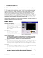
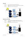
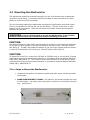
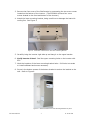
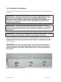
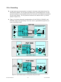
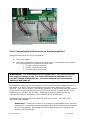
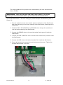
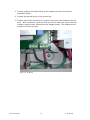
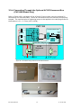
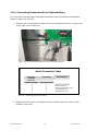
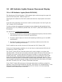
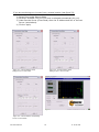
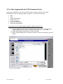
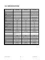
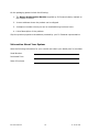
PVP1100, PVP1800, PVP2800
Installation and Operation Manual
PV Powered
Delivering Tomorrow’s Solar Technology . . . Today
PV Powered LLC
11-18-28-704
StarInverter
PVP1100, PVP1800 and PVP2800
Table of Contents
IMPORTANT SAFETY INSTRUCTIONS
2
1.0 INTRODUCTION
3
2.0 INSTALLATION
5
2.1 SELECTING A LOCATION FOR THE STARINVERTER
2.2 MOUNTING THE STARINVERTER
5
6
6
8
9
10
11
13
15
16
2.2.A STEPS TO MOUNT THE STARINVERTER
2.2.B ATTACHING THE OPTIONAL AC DC DISCONNECT BOX
2.3 ELECTRICAL CONNECTION
2.3.A
2.3.B
2.3.C
2.3.D
2.3.E
GROUNDING
CONNECTING THE STARINVERTER TO THE ELECTRICAL GRID
CONNECTING DC WIRES/PV PANELS
CONNECTING THROUGH THE OPTIONAL AC DC DISCONNECT BOX
CONNECTING COMMUNICATIONS
3.0 OPERATION
17
3.1 START UP PROCEDURES FOR THE STARINVERTER
3.2 LED INDICATOR LIGHTS/VACUUM FLUORESCENT DISPLAY
17
18
18
3.2.A LED INDICATOR LIGHTS (MODEL PVP1100)
3.2.B LED INDICATOR LIGHTS/VACUUM FLUORESCENT DISPLAY (MODELS PVP1800 AND
PVP2800)
3.3.A DATA LOGGING WITH THE PVP COMMAND CENTER
19
21
23
4.0 TROUBLESHOOTING
24
5.0 SPECIFICATIONS
26
6.0 LIMITED WARRANTY
27
3.3 PVP COMMAND CENTER
PV Powered LLC
1
11-18-28-704
IMPORTANT SAFETY INSTRUCTIONS
This product has been engineered and manufactured to ensure your personal
safety. Improper use may result in potential electrical shock or burns. Please
read and follow all instructions for installation, use and servicing of this product.
SAVE THESE INSTRUCTIONS – This manual contains important
instructions for the StarInverter model numbers PVP1100, PVP1800 and
PVP2800 that must be followed during installation and maintenance of the
StarInverter.
CAUTION:
♦
All electrical installations should be done in accordance with local electrical codes
and the National Electrical Code (NEC), ANSI/NFPA 70.
♦
Before connecting the StarInverter to the electrical utility grid, approval must be
granted by your utility company. Only qualified electricians should make the
connection.
♦
When exposed to light, PV-arrays create electrical energy that could cause a
hazardous condition. To avoid this, completely cover the surface of all PV-arrays
with opaque (dark) material before wiring them.
♦
The StarInverter contains no user-serviceable parts. Refer servicing to qualified
service personnel.
♦
Do not touch the heat sink located at the top of the StarInverter. Temperatures
can exceed 158 degrees (70° C).
Please read all safety warnings and instructions before
beginning the installation or operation of the
StarInverter.
SAVE THESE INSTRUCTIONS
PV Powered LLC
2
11-18-28-704
1.0 INTRODUCTION
The PV Powered StarInverter is a utility interactive inverter for photovoltaic (PV) systems.
The StarInverter is tied to an electrical source provided by the local utility company (i.e.
on-grid), as well as to the photovoltaic system. The StarInverter contains everything
needed to convert the DC voltage generated by the solar arrays into the AC voltage
required to power a house. Because the inverter is tied to a local utility source, if a
house’s electrical needs exceed the power generated by the solar arrays, the house
automatically taps into its local power supply for that additional electricity. Likewise, if a
house does not utilize all the power generated by the solar panels, the inverter actually
reverses the flow of electricity (i.e. electricity is fed back into the grid). Think of it as
accumulating credits of electricity with the utility for future use.
The information contained within this manual will provide all the information necessary for
successful installation and use of the StarInverter.
Product Features
Command Center Software
Revolutionary software developed by
PV Powered establishes a new industry
standard for ease of use. Monitor the
status and efficiency of energy
generated by the PV system on screen
and in real time.
Easy Installation
The custom designed mounting
brackets and easy-to-follow
instructions make installation simple
and quick.
Figure 1: PVP Command Center
Simple, Innovative Design
Everything needed to power up the StarInverter is contained within the inverter
box, including AC and DC connections and circuits. Low part count keeps costs
down and simplifies the installation and troubleshooting processes.
Safety Features
The StarInverter is designed for safety. Control power comes from the utility grid,
ensuring that power can never be generated during a utility grid failure. The
output stage transformer guarantees isolation of the utility grid and PV modules.
Expandability
The StarInverter is designed with growth in mind, from residential to commercial
use. Most PV system configurations can be accommodated.
System Flexibility
There are three connection options available with the StarInverter. These options
vary depending on your model. See Figures 2 and 3. Refer to your local utility
provider for specific connection requirements per regulations.
PV Powered LLC
3
11-18-28-704
PVP1100
Option 1
Option 2
Option 3
Use the optional PV Powered AC DC Disconnect.
Use the optional PV Powered AC DC Disconnect with a utility grade
meter.
Use a second party AC and DC Disconnect.
Utility Grid
Connection Option #1
PVP1100
Solar Panels
Solar Panel
Solar Panel
Solar Panel
AC/DC
Disconnect
AC Load Center
Connection Option #2
PVP1100
Solar Panels
Solar Panel
Solar Panel
Solar Panel
AC/DC
Disconnect
Connection Option #3
Solar Panels
Solar Panel
Solar Panel
Solar Panel
DC
Disconnect
PVP1100
AC
Disconnect
Figure 2: StarInverter PVP1100 Connection Options
PVP1800 and PVP2800
Option 1
Option 2
Option 3
Use the DC/GFI Circuit Breakers located inside the inverter.
Use the DC/GFI Circuit Breakers inside the inverter with a utility
grade meter.
Use a second party AC and DC Disconnect.
Utility Grid
Connection Option #1
Solar Panels
Solar Panel
Solar Panel
Solar Panel
PVP1800/2800
AC Load Center
Connection Option #2
Solar Panels
Solar Panel
Solar Panel
Solar Panel
PVP1800/2800
Connection Option #3
Solar Panels
Solar Panel
Solar Panel
Solar Panel
DC
Disconnect
PVP1800/2800
AC
Disconnect
Figure 3: StarInverter PVP1800 & PVP2800 Connection Options
PV Powered LLC
4
11-18-28-704
2.0 INSTALLATION
2.1 Selecting a Location for the StarInverter
In choosing a location for the StarInverter, consideration should be given to the following
criteria:
♦
The heat sink temperatures can exceed 158 degrees (70° C). The StarInverter
must be installed so that the top of the unit is not expected to be contacted by
persons.
♦
The StarInverter is suitable for installation both indoors and outdoors and the
enclosure has been given a NEMA 3R rating.
♦
When the StarInverter is installed outdoors, it should be shielded from rain and
direct sunlight, if possible.
♦
The StarInverter is designed to handle the temperature extremes of most
climates. The operating and non-operating ambient temperature range is from
-25° C to 40° C.
♦
The following clearances are recommended for proper placement of the
StarInverter:
• A minimum 36″ clearance between the bottom of the inverter box and
the ground.
• A minimum 12″ clearance above the inverter box for ventilation.
• A minimum 8” clearance around the side of the inverter box so that all
Warning and Caution labels are clearly visible and able to be easily
read.
• Visibility of the operating LED’s and display located at the top front of
the inverter box should also be considered.
♦
If the StarInverter is to be installed in an enclosed cabinet or closet, external
ventilation must be provided to allow for sufficient heat dissipation.
♦
At all times, air circulation around the inverter box must be sufficient.
PV Powered LLC
5
11-18-28-704
2.2 Mounting the StarInverter
The StarInverter should be mounted vertically to a flat, solid surface such as wallboard,
concrete or wood siding. The inverter should be located in close proximity to the solar
panels to minimize the DC wire length.
The two mounting brackets provided make mounting the StarInverter quick and simple.
There is one bracket for the top and one for the bottom. The two screw holes in each
bracket are 16 inches apart. Once the wall studs are located, anchoring the brackets
becomes an easy task.
WARNING: Prior to drilling holes to mount the StarInverter in the location
selected, ensure there are no electrical wires or plumbing in the area.
CAUTION:
The National Electrical Code (NEC) requires that the inverter be connected to a dedicated
circuit with no other outlets or devices connected to the same circuit. See NEC Section
690-64(b)(1). The NEC also places limitations on the size of the inverter and the manner
in which it is connected to the utility grid. See NEC Section 690-64(b)(2).
CAUTION:
To reduce the risk of fire, connect the PVP1800 or PVP2800 only to a circuit with 20 amps
maximum branch-circuit overcurrent protection in accordance with the National Electrical
Code (NEC), ANSI/NFPA 70. The PVP1100 must be connected to a circuit with 15 amps
maximum branch-circuit overcurrent protection in accordance with the National Electrical
Codde (NEC), ANSI/NFPA 70.
2.2.a Steps to Mount the StarInverter
1. Locate the wall studs in the desired location and mark upper mounting bracket
screw holes.
2. MAKE SURE BRACKET IS LEVEL. Drill holes for the screws through the holes
on the bracket. Use heavy-duty molly bolts or anchors if mounting into drywall
only. See Figure 4.
Figure 4: Upper Mounting Bracket
PV Powered LLC
6
11-18-28-704
3. Remove the front cover of the StarInverter by unscrewing the two cover screws
located on the bottom of the inverter. (The PVP2800 will have four cover
screws located on the front and bottom of the inverter.)
4. Attach the lower mounting bracket, being careful not to damage the heat sink
cooling fins. See Figure 5.
Figure 5: Underside of StarInverter and Lower Mounting Bracket
5. Carefully bring the inverter right side up and hang it on the upper bracket.
6. Verify inverter is level. Seal the upper mounting holes on the inverter with
RTV.
7. Mark the locations of the lower mounting bracket holes. Drill holes into studs
or install wallboard anchors as necessary.
8. Screw in the bottom screws of the bottom bracket to anchor the bracket to the
wall. Refer to Figure 6.
Figure 6: Mounted StarInverter with Mounting Brackets in place.
PV Powered LLC
7
11-18-28-704
If installing the PVP1100 with the optional AC DC Disconnect Box, see step 2.2.b. If
installing the PVP1100 without the AC DC Disconnect Box or if installing the PVP1800 or
PVP2800, please proceed to section 2.3 Electrical Connection.
PLEASE NOTE: Leave the inverter cover off to allow for electrical
connection in section 2.3.
2.2.b Attaching the OPTIONAL AC DC Disconnect Box*
*NOTE: Certain utility companies require this equipment per regulations.
you are unsure of these regulations, contact the utility provider. If the
Disconnect Box is not required, proceed to section 2.3.
If
1. Attach the optional StarInverter AC DC Disconnect Box as depicted in Figures 7
through 9. Holes are threaded for four 10-32 screws at the top of the AC DC
Disconnect Box. Place the screws through the holes in the bottom of the
PVP1100 and into the top of the Disconnect Box.
2. Tighten the four screws to a torque value between 2.0 and 2.5 Nm.
Figure 7: AC DC Disconnect Box
Figure 8: Location of screw holes for AC DC
Disconnect Box
Figure 9: Installed AC DC Disconnect Box
PV Powered LLC
8
11-18-28-704
2.3 Electrical Connection
Do not proceed with the electrical connection of the StarInverter until it has been properly
mounted.
WARNING:
Electrical connections must be done in accordance with local
electrical codes and the National Electrical Code (NEC), ANSI/NFPA 70. Use 10
AWG, minimum 90° (194°F), copper wire for all PVP1800 and PVP2800
connections. Use 14 AWG, minimum 90° (194°F), copper wire for all PVP1100
connections. Voltage drop as well as other considerations may dictate that
larger wire sizes be used.
WARNING:
Make sure the main 120/208/240 volt breaker in the main
utility breaker box is switched OFF before wiring the StarInverter. This breaker
should be switched ON only after all wiring has been completed as set forth in
this manual.
WARNING:
Follow the order listed below in wiring the StarInverter. Failure
to do so may result in hazardous voltages or disconnection of contacts.
Terminal connections for the StarInverter are located inside the inverter on the circuit
board at the bottom of the box. Solid wires up to 8 AWG (6mm²) and flexible wires up to
10 AWG (4mm²) are accepted by the AC terminals. Wires up to 6 AWG are accepted by
the DC terminals.
CAUTION:
The input and output circuits are isolated from the enclosure.
System grounding, when required by Sections 690-41, 690-42, and 690-43 of
the National Electric Code (NEC), ANSI/NFPA 70-1999, is the responsibility of
the installer.
Figure 10: Communications, AC and DC ports.
PV Powered LLC
9
11-18-28-704
2.3.a Grounding
♦
♦
A single point ground connection is located in the lower right hand side of the
StarInverter cabinet. The PV panel grounding wire is terminated there. The AC
ground connection is terminated next to the Line and Line 2/Neutral connections
on the circuit board. The PV ground is bolted to the cabinet with a ¼-20 bolt.
(Refer to Figure 12.)
Figure 11 includes schematic representations of the PVP1100, PVP1800, and
PVP2800 single point grounding. The front cover is grounded through the two
cover mounting screws.
+
PVP1100
Control pcb
Power Distribution PCB
PV
DC input
90-180 VDC
120 VAC
60Hz
-
L
Line
Filter
15 A SB
N
GND
DC
Power
Supply
PV GND
To dedicated
AC circuit
System Block Diagram
PVP 1800
Control pcb
15A
+
120 VAC
60Hz
1A
PV
DC input
120-360 VDC
Power Distribution PCB
Line
Filter
-
20 A SB
DC
Power
Supply
PV GND
L1
N
GND
GND
System Block Diagram
PVP 2800
+
Power Distribution PCB
15A
208/240 VAC
60Hz
1A
-
Line
Filter
PV
DC input
240:200-450 VDC
208:180-450 VDC
Control pcb
15 A SB
DC
Power
Supply
PV GND
L1
L2
GND
GND
System Block Diagram
Figure 11: System Block Diagram showing single point ground point
PV Powered LLC
10
11-18-28-704
Figure 12: AC and PV Grounding
2.3.b Connecting the StarInverter to the Electrical Grid
Inside the StarInverter are two circuit boards:
♦
♦
The Control Board
The Power Distribution Board with a D-sub socket or an optional terminal block
for communications to a personal computer and:
• The AC connection terminal
• The DC connection terminal
• The Internal AC grid fuse(s)
WARNING:
For continued protection against risk of fire, replace only with
same type and ratings of fuse. For models PVP1800 and PVP2800 use only
Littelfuse 326020 20 AMP 250V AC. For model PVP1100 use only Littelfuse
326015 15 AMP 250V AC.
PV Powered provides overcurrent protection on the Power Distribution Board with two 20
AMP fuses for models PVP1800 and PVP2800 and with one 15 AMP fuse for model
PVP1100. (See warning above). Overcurrent protection is also provided with the optional
AC DC Disconnect Box available with the PVP1100 and with the included DC/GFI circuit
breakers on the PVP1800 and PVP2800. Additional overcurrent protection for the
inverter’s AC output is provided by circuit breakers at the breaker panel.
The StarInverter is connected to the electrical grid using 3 wires - the LINE, LINE
2/NEUTRAL and GROUND.
Please Note: To avoid an increase in AC voltage to unacceptable values while the
StarInverter is connected, the grid impedance value at the connection point should
be as low as possible. By keeping the grid impedance value low, higher system
efficiency will be achieved.
PV Powered LLC
11
11-18-28-704
The total impedance of the grid plus the interconnecting AC wires should be less
than 1.25 Ohm.
WARNING:
Make sure the main 120/208/240 V breaker at the circuit
breaker panel is switched off before you connect the AC terminal block.
To wire the StarInverter to the main utility grid, follow the steps outlined below (refer to
Figure 13):
1. Run the conduit from the main breaker panel to the bottom of the StarInverter
and insert the fitting in the center opening of the StarInverter, fastening with a
locking nut.
2. Feed the LINE, LINE 2/NEUTRAL and GROUND wires through the conduit and
into the center opening of the StarInverter.
3. Connect the GROUND wire to the terminal marked ‘earth ground’ inside the
StarInverter.
4. Connect the LINE 2/NEUTRAL wire to the terminal marked ‘line 2/neutral’ inside
the StarInverter.
5. Connect the LINE wire to the terminal marked ‘line’ inside the StarInverter.
6. Ensure all connections are wired correctly and properly torqued. Tighten the
terminal block screws to 0.5 Nm.
Figure 13: AC wiring for the line, line 2/neutral and ground wires.
PV Powered LLC
12
11-18-28-704
2.3.c Connecting DC Wires/PV Panels
WARNING:
Before proceeding with the DC wiring, completely cover the
surface of all PV-arrays with dark material to avoid the production of electrical
current.
WARNING:
Make sure the polarity and the PV panel voltage between the +
and the – cable connectors of the PV panels are correct. Then connect the
panels to the DC terminal block on the power distribution board.
The PV panel open circuit voltage should be at or below the listed voltages in Figure 14
under all circumstances. Each DC input to the DC terminal block must be less than the
voltages listed in Figure 14.
StarInverter
Model
PV Panel Open Circuit
Voltage
DC Input to DC
Terminal Block
PVP1100
180VDC
180VDC
PVP1800
360VDC
360VDC
PVP2800
450VDC
450VDC
Figure 14: PV open circuit voltages.
To wire the DC inputs from the PV panels to the StarInverter (refer Figure 15):
Note: Each DC input connection must carry the same input voltage. The StarInverter
allows up to three connections for both the + and the – pole.
1. Calculate the maximum open circuit (no load) for each series panel connection.
FOR ALL TEMPERATURE CONDITIONS, THE OPEN CIRCUIT VOLTAGE
FOR EACH SERIES CONNECTION MUST TOTAL LESS THAN THE OPEN
CIRCUIT VOLTAGE INDICATED IN FIGURE 14 FOR THE
CORRESPONDING STARINVERTER MODEL. Review your panel’s data sheet
for operating temperature ranges.
2. Keep track of the array positive and negative leads and mark them clearly.
3. Route the PV array leads through the far right opening in the StarInverter.
4. Connect each series positive DC lead to the positive terminals of the power
distribution board.
PV Powered LLC
13
11-18-28-704
5. Connect negative DC leads directly to the negative terminal on the power
distribution board.
6. Connect the ground wire(s) to the ground lug.
7. Confirm that the DC disconnect is turned off and remove the material from the
array. With a voltmeter, check the PV array positive leads and confirm that the
voltage is positive when referenced to the negative leads. The reading should
match your series Voc total.
Figure 15: DC Wiring
PV Powered LLC
14
11-18-28-704
2.3.d Connecting Through the Optional AC DC Disconnect Box
(PVP1100 Model Only)
Refer to Figure 16 for a diagram of the AC and DC wiring when using the optional PV
Powered AC DC Disconnect Box. Ensure all connections are wired correctly and properly
torqued. The nominal value of tightening torque to be applied to the clamping screws for
the breakers is 2.0 – 2.5 Nm (18-22 LB-IN).
PVP 1100
+
Control pcb
Power Distribution PCB
PV
DC input
90-180 VDC
120 VAC
60Hz
Line
Filter
-
15 A SB
L
N
GND
DC
Power
Supply
PV GND
System Block Diagram
AC DC
Disconnect
15A
PV Positive
1A
15 A DC Breaker
&GFI
Negative Ground
15A
GND
N
L
15 A
AC Breaker
To dedicated
AC circuit
Figure 16: AC and DC wiring with the AC DC Disconnect Box
Figure 17: Views of the AC DC Disconnect Box
PV Powered LLC
15
11-18-28-704
2.3.e Connecting Communications (Optional Step)
To connect the communications and load the software follow the steps outlined below
(Refer to Figures 18 and 19):
1. Hardwire the communications cable to the communication terminal, or plug in the
D-sub cable to the serial port.
Figure 18: Communications located on the Power Distribution Board
Serial Connection Table
5 Pin Screw
Terminal
Connector
Serial Cable
1
2
3
4
5
7
2
4
3
5
Serial Function
Request to Send (RTS)
Receive Data (Rx)
Data Terminal Ready (DTR)
Transmit Data (Tx)
Signal Ground (SG)
Figure 19: Hardwiring the serial connection
2. Replace the front cover of the StarInverter and tighten the two or four screws
located on the cover.
PV Powered LLC
16
11-18-28-704
3.0 OPERATION
3.1 Start Up Procedures for the StarInverter
WARNING:
Before turning on the StarInverter ensure that the front panel
is closed properly.
WARNING:
The heat sink can reach temperatures in excess of 158º (70ºC).
Care must be taken to not touch the heat sink when in use. Nothing should be
placed on top of the heat sink.
Starting up the StarInverter requires the following steps in the order indicated below:
1. Turn the AC breaker ON.
2. Verify that a red LED light is illuminated.
3. Verify that communication is established with the PVP Command Center
(software on PC). This is an optional step.
4. Remove the dark cover from the PV panels.
5. Check the polarity to make sure the + and – are wired correctly and confirm
that the PV panel open circuit voltage is at or below the level specified in Figure
14.
6. Turn the DC breaker ON.
7. IT IS RECOMMENDED THAT YOU ATTACH A PADLOCK AT THIS TIME TO
PREVENT UNAUTHORIZED ACCESS OR DAMAGE TO THE INVERTER.
8. After 5 minutes, the StarInverter will start to produce power into the AC grid if
all necessary operating conditions are met.
PV Powered LLC
17
11-18-28-704
3.2 LED Indicator Lights/Vacuum Fluorescent Display
3.2.a LED Indicator Lights (Model PVP1100)
The StarInverter PVP1100 displays 7 LED indicator lights visible through the upper left
corner of the front panel. Refer to Figure 20.
These lights will indicate the PVP1100’s status and real-time output power into the AC
Grid.
If the PVP1100’s operating environment is safe to produce power into the AC grid, the
“OK” (Green) LED is illuminated.
If at any moment the operating environment moves outside the safe operating limits,
governed by UL 1741, IEEE 519, and NEC 690, the “FAULT” (Red) LED indicator will be
illuminated.
The StarInverter is continuously monitoring:
1. The AC grid connection to ensure the AC voltage and frequency levels are within
safe operating limits (per UL and NEC specifications).
2. The DC PV panel input(s) to ensure safe operating conditions (per UL and NEC
specifications).
3. The PVP1100 itself to ensure only safe operating conditions exist within the
PVP1100’s operating environment.
If all 3 conditions are met the inverter will illuminate the “OK” (Green) LED.
If any one of the operating conditions is not met there is a fault and the PVP1100 will
illuminate the “FAULT” (Red) LED.
The “FAULT” (Red) LED will illuminate when the PV panel voltage is not within safe
operating limits. This will occur at sunset, when the inverter will turn off for the night. It
may also occur when clouds reduce the amount of sunlight, or when the panels are
covered with snow. Anytime the level of sunlight is too low to produce 90 volts of DC
input (the low end of the PVP1100’s operating range) the inverter will turn off. This
ensures only safe and clean (low distortion) power is being generated. When the panels
are once again exposed to enough sunlight, the PVP1100’s auto-start feature will begin,
and after 5 minutes, the “OK “ (Green) LED should illuminate.
If the “FAULT” (Red) LED continues to illuminate when there is sufficient sunlight for
operation, verify all wiring connections are solid. See Section 4.0 Troubleshooting. If the
PVP1100 Command Center is communicating with the inverter, the exact operating
conditions can be determined in real-time.
PV Powered LLC
18
11-18-28-704
• • • • • • •
t
ul
Fa
K
0w
0w
O
90
70
0w
0w
0w
50
30
10
PVP1100
Utility Interactive Photovoltaic Inverter
Listed 20RP
PV Powered LLC
patent pending
www.pvpowered.com
Figure 20: LED Indicator Lights
3.2.b LED Indicator Lights/Vacuum Fluorescent Display (Models
PVP1800 and PVP2800)
LED INDICATOR LIGHTS
The StarInverter PVP1800 and PVP2800 displays 2 LED indicator lights visible through the
upper left corner of the front panel. These lights will indicate the StarInverter’s status.
If the StarInverter’s operating environment is safe to produce power into the AC grid, the
“OK” (Green) LED is illuminated.
If at any moment the operating environment moves outside the safe operating limits,
governed by UL 1741, IEEE 519, and NEC 690, the “STAND BY” (Red) LED indicator will
be illuminated.
The StarInverter is continuously monitoring:
4. The AC grid connection to ensure the AC voltage and frequency levels are within
safe operating limits (per UL and NEC specifications).
5. The DC PV panel input(s) to ensure safe operating conditions (per UL and NEC
specifications).
6. The StarInverter itself to ensure only safe operating conditions exist within the
operating environment.
If all 3 conditions are met the inverter will illuminate the “OK” (Green) LED.
PV Powered LLC
19
11-18-28-704
If any one of the operating conditions is not met there is a fault and the StarInverter will
illuminate the “STAND BY” (Red) LED.
The “STAND BY” (Red) LED will illuminate when the PV panel voltage is not within safe
operating limits. This will occur at sunset, when the inverter will turn off for the night. It
may also occur when clouds reduce the amount of sunlight, or when the panels are
covered with snow. Anytime the level of sunlight is too low to produce 120 volts for the
PVP1800 or 180 volts for the PVP2800-208 (200 volts for the PVP2800-240) of DC input
(the low end of the StarInverter’s operating range) the inverter will turn off. This ensures
only safe and clean (low distortion) power is being generated. When the panels are once
again exposed to enough sunlight, the StarInverter’s auto-start feature will begin, and
after 5 minutes, the “OK “ (Green) LED should illuminate.
If the “STAND BY” (Red) LED continues to illuminate when there is sufficient sunlight for
operation, verify all wiring connections are solid. See Section 4.0 Troubleshooting. If the
StarInverter Command Center is communicating with the inverter, the exact operating
conditions can be determined in real-time.
VACUUM FLOURESCENT DISPLAY
The vacuum fluorescent display will indicate the StarInverter status and real-time power
output into the AC Grid. This display will provide the following information:
•
•
•
•
AC power produced in real-time
PV input in real-time
Total Output as kW-hr
Greenhouse gases saved in lbs
If a fault has occurred, the display will also provide a fault code that corresponds to a set
of defined faults. Please refer to Section 4.0 Troubleshooting.
PV Powered LLC
20
11-18-28-704
3.3 PVP Command Center
PV Powered has designed a revolutionary software program, the PVP Command Center.
The Command Center will track the status and efficiency of energy generated by the PV
panels and process real-time data generated by the StarInverter.
With the PVP Command Center, multiple inverters can be monitored both locally and
remotely with each inverter being identified by model and serial number. Once the
Command Center is locked onto an inverter, the display window will indicate the array
voltage (PV DC In), the total watts being outputted by the StarInverter (Power Out), and
the heat sink temperature. The Inverter Tracker will graph both the PV DC In (volts) and
Power Out (watts) in hourly increments. The Command Center will also provide
information with regards to system status. If a fault has occurred, the Command Center
will provide a fault code and message to aid in troubleshooting. Refer to Figure 24.
The PVP Command Center requires Windows 98 or higher operating system and a .NET
Framework.
To install the Command Center, follow the steps outlined below:
1. Insert the PVP Command Center CD into the CD-Rom drive or download the file
provided by your distributor.
2. If your computer does not include a .NET Framework, first install the dotnetfx.exe
program by clicking on the icon.
3. Install the PVP Command Center by clicking on the StarInverter Setup icon and
following the instructions on your screen.
4. Retain the software for future use. In order to view the operating status of the
StarInverter remotely, each user must have the Command Center installed.
Once the software is installed, click on the StarInverter icon on your desktop. This will
bring up the main window.
Click on File>New Inverter to bring up the Communication Setup Dialog Window.
If you will be monitoring your inverter locally (see figure 21):
1) Select None under Remote Mode.
2) Select an available COM port.
3) Click on Apply.
If you or others will be monitoring your inverter remotely (see figure 22):
1) Select Server under Remote Mode.
2) Select an available COM port (this may be selected automatically for you).
3) Your IP Address and Port under Local Server (Server Mode) should
automatically be displayed.
4) Note the IP Address.
5) Click on Apply.
PV Powered LLC
21
11-18-28-704
If you are monitoring your inverter from a remote location (see figure 23):
1) Select Client under Remote Mode.
2) Select an available Com port (this may be selected automatically for you).
3) Under Remote Server (Client Mode) enter the IP Address and Port of the host
Server (noted above).
4) Click on Apply.
Figure 21: Communication Setup
Dialog screen in Local mode.
Figure 22: Communication Setup
Dialog screen in Server mode.
.
Figure 24: PVP Command Center Main Screen
Figure 23: Communication Setup Dialog
screen in Client mode.
PV Powered LLC
22
11-18-28-704
3.3.a Data Logging with the PVP Command Center
Information obtained by the PVP Command Center is easily exported to an Excel
spreadsheet where the following data is logged in one-minute increments:
•
•
•
•
•
•
•
Date
Time
Utility RMS Voltage
PV RMS Current
PV DC In Voltage
Power Out (AC Watts)
Heat Sink Temperature
To activate the Excel data logging capability (Refer to Figure 25):
1) From the Main Screen of the Command Center click on Setup>Toggle Data
Logging Off/On to bring up the “Save Inverter Data As . . . “ window.
2) Name data logging file and save in desired location.
3) Open the data logging file to display the specific inverter information outlined
above.
Figure 25: Data Logging
PV Powered LLC
23
11-18-28-704
4.0 TROUBLESHOOTING
If the StarInverter’s “STAND BY” LED remains red for a prolonged period (longer than the
5 minute timer required by code), and all of the operating parameters are within
specification (see system specifications), the AC breaker or AC disconnect should be
turned to the OFF position for 1 minute and then returned to the ON position. If the DC
and AC voltage levels are within specification, the red “STAND BY” LED will not be
illuminated. The green “OK” LED will be illuminated and the inverter will produce power
after 5 minutes. If the red “STAND BY” light remains illuminated, double-check all
connections and voltage levels. If the red “STAND BY” light is still illuminated, contact
your authorized dealer/distributor for product support.
In addition to the above fault indicators, the PVP Command Center software will indicate
system status. If a fault has occurred, a fault message as well as the corresponding code
will be displayed.
The vacuum fluorescent display (models PVP1800 and PVP2800) will provide the following
codes when a fault has occurred:
First Code:
PDPA FAULT
VOLTAGE FAULT
GROUND FAULT
LOW POWER FAULT
0x8000
0x1000
0x0400
0x0200
power module generated fault
Code 3 will contain further information
CPU LOAD FAULT
OVERCURRENT FAULT
PRECHARGE FAULT
HEATSINK TEMP FAULT
AMBIENT TEMP FAULT
0x0100
0x0040
0x0020
0x0004
0x0001
Second Code:
0x0000
will always remain zero
0x0400
0x0200
0x0100
0x0080
0x0020
0x0010
0x0002
0x0001
AC voltage sensing missing per UL
array power too low for max power
tracking
software overload
Third Code: (Voltage Faults)
PLL FAULT
AC OVERVOLTAGE FAULT
AC UNDERVOLTAGE FAULT
AC FREQUENCY FAULT
DC UNDERVOLTAGE FAULT
DC OVERVOLTAGE FAULT
P15 FAULT
PS FAULT
array voltage too low
+15V supply out of specifications
+5V supply out of specifications
As indicated above, there are three 16-bit codes assigned to describe faults, one of which
will always remain zero. More than one fault can be represented at a time. This will be
indicated by a fault with a code equal to the sum of the individual faults.
PV Powered LLC
24
11-18-28-704
For example:
EX 1: Fault Code 1000 0000 0480
The first code indicates this is a voltage fault of some kind.
The 4 in code three indicates a PLL fault.
The 8 in code three indicates the AC frequency was out of bounds.
EX 2: Fault Code 8004 0000 0000
The 8 in the first code indicates a power module fault.
The 4 in the first code indicates a heatsink over temperature fault.
WARNING:
These servicing instructions are for use by qualified personnel
only. To reduce the risk of electric shock, do not perform any servicing other
than that specified in the operating instructions unless you are qualified.
PV Powered LLC
25
11-18-28-704
5.0 SPECIFICATIONS
Specifications
Maximum System Voltage
Operating DC Voltage
Range
Maximum DC Operating
Current
Maximum Array Short
Circuit Current (DC)
Operating AC Voltage
Range
Operating Frequency
Range
Nominal AC Output
Voltage
Normal Output Frequency
Maximum Continuous
Output AC Current
Maximum Output Fault
Current (AC)
Output Overcurrent
Protection
Peak Output Power
Peak Efficiency at @ 40°C
Ambient Temperature
Enclosure
Dimensions (WxDxH)
Weight
Cooling
Relative Humidity
Ambient Temperature
Range
Environmental Rating
Listings
PV Powered LLC
PVP1100
PVP1800
PVP2800
180VDC
360VDC
450VDC
90-180VDC
120-360VDC
208: 180VDC-390VDC
240: 200VDC-390VDC
14A
15A
15A
15A
15A
15A
106V-132V
106V-132V
208: 183V-229V
240: 211V-264V
59.3Hz-60.5Hz
59.3Hz-60.5Hz
59.3Hz-60.5Hz
120V
120V
208V or 240V
60Hz
60Hz
60Hz
11.5A
15A
14A
15A
15A
15A
15A
20A
20A
1100W
1800W
2800W
95%
95%
97.6%
Aluminum-NEMA 3R to UL
50 Standards
13.1” x 6.5” x 19.75”
(with optional AC DC
Disconnect-13.1” x 6.5” x
26.75”)
Aluminum-NEMA 3R to UL
50 Standards
Aluminum-NEMA 3R to UL
50 Standards
13.1” x 6.5” x 19.75”
15” x 7.5” x 21.75”
38lbs
46lbs
74lbs
Natural Convection
Natural Convection
Natural Convection
0% to 100% Condensing
0% to 100% Condensing
0% to 100% Condensing
-25°C to +40°C
-25°C to +40°C
-25°C to +40°C
Conformal Coating per UL
Standards
UL 1741, IEEE 519, IEEE
929, NEC 690
Conformal Coating per UL
Standards
UL 1741, IEEE 519, IEEE
929, NEC 690
Conformal Coating per UL
Standards
UL 1741, IEEE 519, IEEE
929, NEC 690
26
11-18-28-704
6.0 LIMITED WARRANTY
PV Powered, LLC provides a limited warranty that covers defects of your StarInverter
caused by material or manufacturing faults. The warranty period is for 10 years and
begins on the date of purchase by the original end user.
This limited warranty is made only to the original purchaser of the StarInverter, and is not
transferable to any subsequent owner.
PV Powered will, at its option, repair or replace the defective component(s) free of charge,
provided that you notify PV Powered of the defect during the warranty period and have a
dated proof of purchase. PV Powered reserves the right to inspect the faulty
component(s) and determine if the defect is due to material or manufacturing flaws. PV
Powered also reserves the right to charge for service time expended if the defect is not
due to material or manufacturing flaws or is not for some other reason subject to this
limited warranty.
PV Powered does not warrant its products from any and all defects or damage caused by:
•
•
•
•
•
•
•
Normal wear and tear
Shipping or transportation damages
Improper installation
Exposure to unsuitable environmental conditions, including but not limited to
damage due to lightning strikes
Unauthorized or abnormal use or operation
Negligence or accidents
Material or workmanship not provided by PV Powered or its authorized service
centers
This warranty also does not cover costs related to the removal, installation, or
troubleshooting of your electrical systems.
PV Powered will, at its option, use new and/or reconditioned parts in performing warranty
repair and in building replacement products. PV Powered reserves the right to use parts
or products of original or improved design in the repair or replacement. If PV Powered
repairs or replaces a product, its warranty continues for the remaining portion of the
original warranty period or 90 days from the date of the return shipment to the customer,
whichever period expires later. All replaced products and all parts removed from repaired
products become the property of PV Powered.
PV Powered covers both parts and labor necessary to repair the product, and return
shipment to the customer via a PV Powered selected non-expedited surface freight carrier
within the United States and Canada.
EXCEPT FOR THIS EXPRESS LIMITED WARRANTY, PV POWERED EXPRESSLY
EXCLUDES ALL WARRANTIES WITH RESPECT TO THE STARINVERTER, EXPRESS
AND IMPLIED, INCLUDING BUT NOT LIMITED TO THE WARRANTY OF
MERCHANTABILITY, THE WARRANTY OF FITNESS FOR PARTICULAR PURPOSE,
AND ANY WARRANTIES THAT MAY HAVE ARISEN FROM COURSE OF DEALING OR
USAGE OF TRADE.
TO THE MAXIMUM EXTENT PERMITTED BY LAW, PV POWERED’S AGGREGATE
MONETARY LIABILITY TO THE CUSTOMER FOR ANY REASON AND FOR ANY AND
PV Powered LLC
27
11-18-28-704
ALL CAUSES OF ACTION, WHETHER IN CONTRACT, TORT OR OTHERWISE, WILL
NOT EXCEED THE AMOUNT PAID TO PV POWERED FOR THE STARINVERTER. PV
POWERED WILL NOT BE LIABLE TO YOU UNDER ANY CAUSE OF ACTION,
WHETHER IN CONTRACT, TORT OR OTHERWISE, FOR ANY INDIRECT, SPECIAL,
INCIDENTAL, CONSEQUENTIAL, OR PUNITIVE DAMAGES, EVEN IF PV POWERED
HAS BEEN ADVISED OF THE POSSIBILITY OF SUCH DAMAGES. THE PRICE FOR
THE STARINVERTER AND PV POWERED’S OBLIGATIONS UNDER THIS EXPRESS
LIMITED WARRANTY ARE CONSIDERATION FOR LIMITING PV POWERED’S
LIABILITY.
IF THIS PRODUCT IS A CONSUMER PRODUCT, FEDERAL LAW DOES NOT ALLOW
AN EXCLUSION OF IMPLIED WARRANTIES. TO THE EXTENT YOU ARE ENTITLED
TO IMPLIED WARRANTIES UNDER FEDERAL LAW, TO THE EXTENT PERMITTED BY
APPLICABLE LAW THEY ARE LIMITED TO THE DURATION OF THIS LIMITED
WARRANTY. SOME STATES AND PROVINCES DO NOT ALLOW LIMITATIONS OR
EXCLUSIONS ON IMPLIED WARRANTIES OR ON THE DURATION OF AN IMPLIED
WARRANTY OR ON THE LIMITATION OR EXCLUSION OF INCIDENTAL OR
CONSEQUENTIAL DAMAGES, SO THE ABOVE LIMITATION(S) OR EXCLUSION(S)
MAY NOT APPLY TO YOU. THIS LIMITED WARRANTY GIVES YOU SPECIFIC
LEGAL RIGHTS. YOU MAY HAVE OTHER RIGHTS WHICH MAY VARY FROM STATE
TO STATE OR PROVINCE TO PROVINCE. IN THE EVENT OF A DISPUTE BETWEEN
PV POWERED AND THE CONSUMER COVERED UNDER THIS WARRANTY, THE
CONSUMER AGREES TO RESOLVE ANY SUCH DISPUTE USING BINDING
ARBITRATION.
IN THE EVENT OF A DISPUTE BETWEEN PV POWERED AND ANY PURCHASER
COVERED UNDER THIS WARRANTY, TO THE MAXIMUM EXTENT ALLOWED BY
LAW, THE PURCHASER AGREES TO RESOLVE ANY AND ALL SUCH DISPUTES
USING BINDING ARBITRATION IN ACCORDANCE WITH THE RULES AND
PROCEDURES OF THE AMERICAN ARBITRATION ASSOCIATION. THE PRICE FOR
THE STARINVERTER AND PV POWERED’S OBLIGATIONS UNDER THIS EXPRESS
LIMITED WARRANTY ARE CONSIDERATION FOR THIS BINDING ARBITRATION
PROVISION.
If your product requires troubleshooting or warranty service, contact your installer or
dealer. If you are unable to contact your dealer, or the dealer is unable to provide
service, contact PV Powered directly at: [email protected]
Return Procedure
Before returning the product directly to PV Powered, you must first obtain a Return
Authorization Number from PV Powered. The product must also be shipped prepaid.
When you contact a PV Powered representative, please have the following information
ready:
1. The serial number of the product
2. The reason for the return
3. A copy of your dated proof of purchase
When you return the product to PV Powered, PV Powered advises that the original
packaging or equivalent be used and that the product is shipped fully insured. PV
Powered is not responsible for damage to the product due to improper packaging.
PV Powered LLC
28
11-18-28-704
On the packaging please include the following:
1. The Return Authorization Number supplied by PV Powered clearly marked on
the outside of the box.
2. A return address where the product can be shipped.
3. A telephone number where you can be reached during business hours.
4. A brief description of the problem.
Ship the product prepaid to the address provided by your PV Powered representative.
Information About Your System
Note the following information for your records and retain your dated proof of purchase:
Serial Number
Purchased From
Date of Purchase
PV Powered LLC
29
11-18-28-704
PV Powered LLC
30
11-18-28-704
Notes:
PV Powered LLC
31
11-18-28-704
PV Powered LLC
32
11-18-28-704
PV Powered
Delivering Tomorrow’s Solar Technology . . . Today
PV Powered, LLC
160 SW Scalehouse Loop, #208
Bend, OR 97702
Phone 541-312-3832 • Fax 541-383-2348
www.pvpowered.com