1
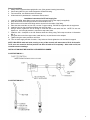
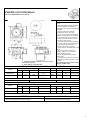
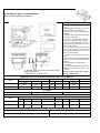
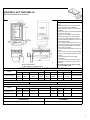
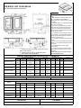
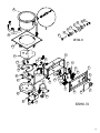
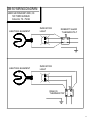
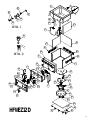
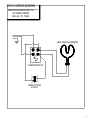
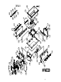
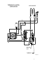
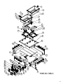
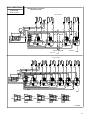
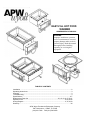
EASY-FILL HOT FOOD
WARMER
OWNERS/SERVICE MANUAL
WARNING:
Improper installation, operation,
service or maintenance can cause
property damage and/or result in
personal injury. Read this manual
thoroughly before installing
operating, or servicing this
equipment.
TABLE OF CONTENTS
Installation .............................................................................................................................2
Operating Instructions ............................................................................................................3
Cleaning .................................................................................................................................3
Troubleshooting......................................................................................................................3
Specifications ..................................................................................................................... 4-7
Replacement Parts List ........................................................................8,9,12,13,16,17,20,21
Exploded View.......................................................................................................10,14,18,22
Wiring Diagram .....................................................................................................11,15,19,23
Warranty...............................................................................................................................24
APW Wyott Foodservice Equipment Company
729 Third Avenue Dallas, TX 75226
(214) 421-7366 FAX (214) 565-0976
General Installation
1. Always clean equipment thoroughly before use. (See general cleaning instructions.)
2. Check rating label for your model designation & electrical rating.
3. For best results, use stainless steel countertops.
4. All dimensions in parenthesis in centimeters unless noted.
1.
2.
3.
4.
5.
6.
7.
8.
9.
10.
Installation instructions for EZ well supply line
Install P/N 54508, brass fitting in each end of the solenoid using Teflon tape (not supplied).
Wrap the threads of the fitting as shown in the illustration, NO. 1.
Remove the nut from the brass fitting and the sleeve from the inside of the fitting.
Place the sleeve and the nut, nut first, over the ¼” copper tubing, P/N 54578, supplied with the equipment.
Install the line into the solenoid and tighten the nut finger tight.
Using a wrench, tighten the nut far enough to crush the sleeve and attach the line. NOTE: Do not over
tighten nut. Just enough pressure is required to stop water leaks.
Install the 3/8 x ¼ adapter to the 3/8 stainless steel tube fitting using Teflon tape as shown in illustration
NO. 2.
Using the other end of the copper tube, install the line, nut, and sleeve to the adapter.
Tighten using the same procedure as before.
Turn on water supply and look for leaks. If any leaks are found, tighten the nuts until leak is stopped.
NOTE: With EZ-fill multi-well units, turning on any of the controls will start water to fill all of the wells.
To fill, turn one control to the first position and allow all wells to fill completely. After wells are full, set
controls to desired settings.
INSTALLATION MUST BE DONE BY AUTHORIZED PLUMMER.
ILLUSTRATION NO. 1.
ILLUSTRATION NO. 2.
2
General Operation Instructions
1. All foodservice equipment should be operated by trained personnel.
2. Do not allow your customers to come in contact with any surface labeled “CAUTION HOT.”
3. Do not cook, warm or hold food directly in liner pans (well pans). Always use steam table pans / insets, etc.
Steam table pan depth should not exceed 6”.
4. Never hold food below 150º F (66º C).
Wet set-up and operation procedures (Units with drains)
1. Turn thermostat control to "10" setting or if equipped with infinite controls to “7” or “HI”. Preheat for
approximately 30 minutes. Pans will fill, to correct level, with water to white probe.
2. Place covered inset with preheated product into well.
3. Readjust control after another 30 minutes of operation to the “6” setting depending on the amount and/or
thickness of product.
4. Keep inset / steamtable pan(s) covered to maintain ideal serving temperature.
5. Water is automatically kept at correct level.
NOTE: Turning on any control will activate autofill.
General Cleaning Instructions
1. NEVER clean any electrical unit by immersing it in water. Turn off before surface cleaning.
2. Always clean equipment thoroughly before first use. Clean unit daily. Except where noted on charts: Use
warm, soapy water. Mild cleansers & PLASTIC scouring pads may be used to remove baked-on food &
water scale.
3. Turn off electrical units before cleaning or servicing. All service should be performed by an APW authorized
agency.
GENERAL TROUBLESHOOTING
Always Ask & Check:
1. Is the unit connected to a live power source?
2. Check the circuit breaker.
3. Is power switch on & pilot light glowing?
4. Check rating label. Are you operating unit on proper voltage?
If the above checks out, and you still have problems, call an APW authorized service agency.
3
APW EZFILL HOT FOOD WELLS
PART NO'S BEGINNING WITH WHFW
INSTALLATION
1. Water fill is 3/8 (1.0) tubing connection on left
back of left controls
2. Main drain is 3/4 female NPT.
1. Follow general installation instructions on
page 3.
2. Make applicable Cut-Out per above table.
Note: Unit is designed for installation in
stainless steel tops. Optional wood mounting
kit available.
3. Apply putty tape to the underside
perimeter of the well rim outer edge.
4. Apply a 1/4" (.6) bead of silicone sealant
adjacent to the putty tape on the well flange.
5. Drop well into opening from the top and
push down until entire parameter of rim is
flush with the counter surface.
6. From below the counter surface insert an
8" to 10" (20 to 25 cm) flat tip screwdriver into
the locking ring tab slots and twist in a
clockwise motion to lock well in place.
7. Trim excess putty and sealant from around
well rim.
8. Mount control to front panel using
hardware. Maintain 4" (10.2) clearance
between well and front panel.
9. Check nameplate for proper voltage.
Connect power.
10. Connect overflow tube onhot food well to
suitable tubing to handle 212 F water. Run to
open drain.
Note: Electrically connect units to comply
with local and NEC codes.
GENERAL SPECIFICATIONS (APW EZFILL HOT FOOD WELLS)
OUTSIDE DIMENSIONS
MODEL
SM50EZ WELL
INSIDE DIMENSIONS CUT OUT
CONTROL CUT OUT
A
B
C
E
D
F
G
10.34"
(26.3)
8.38"
(21.3)
6.44"
(16.4)
8.32"
(21.1)
10.875"
(27.6)
5.0"
(12.7)
12.5"
(31.8)
SHIP WT.
13 Lbs. (5.9 Kg)
OPTIONS
Description: Lever Operated Drain Valve
Stock No.: 56360
Drain Manifold: Fabricated to Unit, Required
ELECTRICAL SPECIFICATIONS
Electrical Ratings 500 @ 208V / 660 @ 240V
MODEL
SM50EZ WELL
Volts
Watts
Amps 1-Phase
Max Amps 3-Phase
208/240
500/660
2.4 / 2.75
n/a
NOTE: CUT-OUT SIZES ARE DIFFERENT FROM STANDARD APW HFW'S
OPERATION
1. Follow General Operating Instructions on page 3.
CLEANING
1. Follow General Cleaning Instructions on page 3.
4
APW EZFILL HOT FOOD WELLS
PART NO'S BEGINNING WITH WHFW
INSTALLATION
1. Water fill is 3/8 (1.0) tubing connection on left
back of left controls
2. Main drain is 3/4 female NPT.
1. Follow general installation instructions on
page 3.
2. Make applicable Cut-Out per above table.
Note: Unit is designed for installation in
stainless steel tops. Optional wood mounting
kit available.
3. Apply putty tape to the underside perimeter
of the well rim outer edge.
4. Apply a 1/4" (.6) bead of silicone sealant
adjacent to the putty tape on the well flange.
5. Drop well into opening from the top and
push down until entire parameter of rim is flush
with the counter surface.
6. From below the counter surface insert an 8"
to 10" (20 to 25 cm) flat tip screwdriver into the
locking ring tab slots and twist in a clockwise
motion to lock well in place.
7. Trim excess putty and sealant from around
well rim.
8. Mount control to front panel using hardware.
Maintain 4" (10.2) clearance between well and
front panel.
9. Check nameplate for proper voltage.
Connect power.
10. Connect overflow tube onhot food well to
suitable tubing to handle 212 F water. Run to
open drain.
Note: Electrically connect units to comply
with local and NEC codes.
GENERAL SPECIFICATIONS (APW EZFILL HOT FOOD WELLS)
OUTSIDE DIMENSIONS
MODEL
SHFWEZ-12D WELL
CUT OUT
CONTROL CUT OUT
A
B
C
D
E
F
G
15.21"
(38.6)
12.71"
(32.3)
13.49"
(34.3)
13.75"
(34.9)
11.50"
(29.2)
5.0"
(12.7)
12.5"
(31.8)
SHIP WT.
22 Lbs. (10.6 Kg)
OPTIONS
Description: Lever Operated Drain Valve
Stock No.: 56360
Drain Manifold: Fabricated to Unit, Required
ELECTRICAL SPECIFICATIONS
MODEL
SHFWEZ-12D WELL
Electrical Ratings 500 EA. @ 208V / 660 EA. @ 240V
Volts
Watts
Amps 1-Phase
Max Amps 3-Phase
208/240
500/660
2.4/2.75
n/a
NOTE: CUT-OUT SIZES ARE DIFFERENT FROM STANDARD APW HFW'S
OPERATION
1. Follow General Operating Instructions on page 3.
CLEANING
1. Follow General Cleaning Instructions on page 3.
5
APW EZFILL HOT FOOD WELLS
PART NO'S BEGINNING WITH WHFW
INSTALLATION
1. Water fill is 3/8 (1.0) tubing connection on left
back of left controls
2. Main drain is 3/4 female NPT.
1. Follow general installation instructions on
page 3.
2. Make applicable Cut-Out per above table.
Note: Unit is designed for installation in
stainless steel tops. Optional wood mounting
kit available.
3. Apply putty tape to the underside perimeter
of the well rim outer edge.
4. Apply a 1/4" (.6) bead of silicone sealant
adjacent to the putty tape on the well flange.
5. Drop well into opening from the top and
push down until entire parameter of rim is flush
with the counter surface.
6. From below the counter surface insert an 8"
to 10" (20 to 25 cm) flat tip screwdriver into the
locking ring tab slots and twist in a clockwise
motion to lock well in place.
7. Trim excess putty and sealant from around
well rim.
8. Mount control to front panel using hardware.
Maintain 4" (10.2) clearance between well and
front panel.
9. Check nameplate for proper voltage.
Connect power.
10. Connect overflow tube onhot food well to
suitable tubing to handle 212 F water. Run to
open drain.
Note: Electrically connect units to comply
with local and NEC codes.
GENERAL SPECIFICATIONS (APW EZFILL HOT FOOD WELLS)
OUTSIDE DIMENSIONS
MODEL
SHFWEZ-1 WELL
CUT OUT
CONTROL CUT OUT
A
B
C
H
D
E
F
G
15.38"
(39.1)
23.44"
(59.5)
13.80"
(35.10)
12.85"
(32.6)
14.25"
(36.2)
22.25"
(56.5)
5.0"
(12.7)
12.5"
(31.8)
SHIP WT.
24 Lbs. (10.9 Kg)
OPTIONS
Description: Lever Operated Drain Valve
Stock No.: 56360
Drain Manifold: Fabricated to Unit, Required
ELECTRICAL SPECIFICATIONS
MODEL
SHFWEZ-1 WELL
Electrical Ratings 1200 EA. @ 208V / 1600 EA. @ 240V
Electrical Ratings 1600 EA. @ 208V
Volts
Watts
Amps 1-Phase
Max Amps 3-Phase
Volts
Watts
Amps 1-Phase
Amps 3-Phase
208/240
1200/1600
5.8 / 6.7
n/a
208
1600
7.7
n/a
NOTE: CUT-OUT SIZES ARE DIFFERENT FROM STANDARD APW HFW'S
OPERATION
1. Follow General Operating Instructions on page 3.
CLEANING
1. Follow General Cleaning Instructions on page 3.
6
APW EZFILL HOT FOOD WELLS
PART NO'S BEGINNING WITH WHFW
INSTALLATION
1. Water fill is 3/8 (1.0) tubing connection on left
back of left controls
2. Overflow drain is 1/2" (1.3) OD tube outlet.
3. Main drain is 3/4 female NPT.
1. Follow general installation instructions on
page 3.
2. Make applicable Cut-Out per above table.
Note: Unit is designed for installation in
stainless steel tops. Optional wood mounting
kit available.
3. Apply putty tape to the underside perimeter
of the well rim outer edge.
4. Apply a 1/4" (.6) bead of silicone sealant
adjacent to the putty tape on the well flange.
5. Drop well into opening from the top and
push down until entire parameter of rim is flush
with the counter surface.
6. From below the counter surface insert an 8"
to 10" (20 to 25 cm) flat tip screwdriver into the
locking ring tab slots and twist in a clockwise
motion to lock well in place.
7. Trim excess putty and sealant from around
well rim.
8. Mount control to front panel using hardware.
Maintain 4" (10.2) clearance between well and
front panel.
9. Check nameplate for proper voltage.
Connect power.
10. Connect overflow tube onhot food well to
suitable tubing to handle 212 F water. Run to
open drain.
Note: Electrically connect units to comply
with local and NEC codes.
GENERAL SPECIFICATIONS (APW EZFILL HOT FOOD WELLS)
OUTSIDE DIMENSIONS
MODEL
CUT OUT
CONTROL CUT OUT
SHIP WT.
A
B
C
J Overflow
D
E
F
G
H
SHFWEZ-2D WELL
29.42"
(74.2)
23.44"
(59.5)
27.79"
(70.6)
13.87"
(35.2)
28.5"
(72.4)
22.5"
(57.2)
5.0"
(12.7)
16.50"
(41.9)
n/a
48 Lbs. (21.8 Kg)
SHFWEZ-3D WELL
43.46"
(110.4)
23.44"
(59.5)
41.83"
(106.2)
27.92"
(70.9)
42.5"
(108.0)
22.5"
(57.2)
5.0"
(12.7)
33.50"
(85.1)
12.50"
68 Lbs. (30.8 Kg)
SHFWEZ-4D WELL
57.50"
(146.0)
23.44"
(59.5)
55.87"
(141.9)
27.92"
(70.9)
56.5"
(143.5)
22.5"
(57.2)
5.0"
(12.7)
16.50"
(41.9)
n/a
98 Lbs. (44.4 Kg)
SHFWEZ-5D WELL
71.54"
(181.7)
23.44"
(59.5)
69.92"
(177.6)
41.96"
(106.6)
70.5"
(179.1)
22.5"
(57.2)
5.0"
(12.7)
33.50"
(85.1)
n/a
118 Lbs. (53.5 Kg)
SHFWEZ-6D WELL
85.59"
(217.4)
23.44"
(59.5)
83.96"
(213.2)
41.96"
(106.6)
84.50"
(214.6)
22.5"
(57.2)
5.0"
(12.7)
33.50"
(85.1)
n/a
260 Lbs. (117.9 Kg)
OPTIONS
Description: Lever Operated Drain Valve
Stock No.: 56360
Drain Manifold: Fabricated to Unit, Required
ELECTRICAL SPECIFICATIONS
MODEL
Electrical Ratings 1200 EA. @ 208V / 1600 EA. @ 240V
Electrical Ratings 1600 EA. @ 208V
Volts
Watts
Amps 1-Phase
Max Amps 3-Phase
Volts
Watts
Amps 1-Phase
Amps 3-Phase
SHFWEZ-2D
208/240
2400/3200
12 / 14
10 / 12
208
3200
16
14
SHFWEZ-3D
208/240
3600/4800
18 / 20
10 / 12
208
4800
23
14
SHFWEZ-4D
208/240
4800/6400
24 / 27
16 / 18
208
6400
31
21
SHFWEZ-5D
208/240
6000/8000
29 / 34
20 / 24
208
8000
39
27
SHFWEZ-6D
208/240
7200/9600
35 / 40
20 / 24
208
9600
47
27
NOTE: CUT-OUT SIZES ARE DIFFERENT FROM STANDARD APW HFW'S
OPERATION
1. Follow General Operating Instructions on page 3.
CLEANING
1. Follow General Cleaning Instructions on page 3.
7
REPLACEMENT PARTS CATALOG
SM50EZ
ROUND SOUP WELL DROP-IN WITH EZ LOCK
SM50EZ, P/N EZSM50-7D – 208/240V-500/660W
8
SM50EZ
EZ FILL MULTI WELLS,
ITEM STOCK
NO. NO. DESCRIPTION
ITEM STOCK
NO. NO. DESCRIPTION
1
2
3
4
5
6
7
8
9
10
11
12
27
28
29
30
31
32
33
34
35
36
37
38
39
40
41
42
43
44
45
13
14
15
16
17
18
19
20
21
22
23
24
25
26
54561 CONTROL BOX W/ASSY 12.50 ”
54503 BEZEL CONTROL 12.50 “
56527 THERMOSTAT 36” CAPILLARY
56528 KNOB, BLACK
63012 INDICATOR LIGHT (56530)
54577 ADAPTER, ¼” TUBE TO 3/8 PIPE
54578 TUBING, COPPER, ¼
55343 90 DEGREE CONDUIT CONNECTOR
54511 OCTAL BASE USE WITH 54510
54524 BRACKET, SOLENOID VALVE
54513 WATER SOLENOID VALVE
54510 LIQUID LEVEL CONTROL OCTAL BASE
XXXX LIQUID LEVEL CONTROL OPEN BOARD
54512 HOLD DOWN STRAP USE WITH 54510
30201 TERMINAL BLOCK
54508 BRASS FITTING 1/8 NPT X ¼
COMPRESSION
54572 7 QT. ROUND WELL PAN W/COPPER
TUBE
50817 PLATE, HEAT DIFFUSER
55964 HEATING ELEMENT 208/240V,
500W/660W
55696 BRACKET, ELEMENT HOLDER
55695 BRACKET, ELEMENT HOLDER
89025 10-24 SPEED NUT
55992 BOTTOM COVER
89059 #10 EXTERNAL LOCK WASHER
89061 NUT,HEX 10-24
54544 O-RING FOR PROBE HOLDER
54543 PROBE HOLDER
54546
54549
54545
88971
54548
89063
56542
88961
89054
88993
89073
51016
55342
55340
89120
88889
88977
55333
55402
WASHER ½-20 SS
NUT, HEX 1/2-20
O-RING FOR SCREW
SCREW 8-32 X 1-1/2 SS
SPACER, PROBE HOLDER
NUT, HEX 8-32
PLATE, DIAL-WELLS
10-24 HEX NUT, GREEN-GROUND
6-32 KEPS NUT
10-32 X 3/8 TRUSS HEAD SCREW
#8 X 1/2 SHEET METAL SCREW
COVER, TERMINAL
3/8” CONDUIT
ANTI-SHORT BUSHING
JIFFY CLIP
8 X ½ AB SMS, PHL TRUSS
6-32 X 1.0 SLOTTED PAN HEAD
WOOD MOUNT KIT SM-50-7
EZ LOCK CLIP 4 TAB
HARDWARE NOT SHOWN
56655
54532
54533
54534
54535
54536
DRAIN STRAINER
WIRE SET TWO WELL
WIRE SET THREE WELL
WIRE SET FOUR WELL
WIRE SET FIVE WELL
WIRE SET SIX WELL
9
16
28
31 32
27
B
26
25
29
45
30
DETAIL B
44
1
17
37
10
23
41
13
24
36
35
15 6
20
21
34
11
7
8
2
14
18
19
3
35
5
12
43
9
40
42
22
33
4
39
38
23
24
EZSM50-7D
10
SM-50 WIRING DIAGRAM
AMERICAN PERMANENT WARE, INC.
729 THIRD AVENUE
DALLAS, TX. 75226
HEATING ELEMENT
HEATING ELEMENT
INDICATOR
LIGHT
ROBERT SHAW
THERMOSTAT
H1
L1
H2
L2
INDICATOR
LIGHT
RANCO
THERMOSTAT
H1
H2
L1
L2
11
REPLACEMENT PARTS CATALOG
EZ12D4B
SMALL FRAME INSULATED TOP MOUNT EZ FILL HOT FOOD WELLS
HFWEZ12D, P/N EZ12D4B – 208/240V-500/660W
12
HFWEZ12D
EZ FILL MULTI WELLS,
ITEM STOCK
NO. NO. DESCRIPTION
ITEM STOCK
NO. NO. DESCRIPTION
1
2
3
4
5
6
31
32
33
34
35
36
37
38
39
40
7
8
9
10
11
12
13
14
15
16
17
18
19
20
21
22
23
24
25
26
27
28
29
30
54561 CONTROL BOX W/ASSY 12.50 ”
55342 3/8” CONDUIT
55340 ANTI-SHORT BUSHING
54578 TUBING, COPPER, ¼
88889 8 X ½ AB SMS, PHL TRUSS
54508 BRASS FITTING 1/8 NPT X ¼
COMPRESSION
56406 WRAPPER, ½ SIZE OUTER
54567 ½ SIZE WELL PAN W/COPPER TUBE
54571 WRAPPER OUTER END
30201 TERMINAL BLOCK
56505 KNOB, BLACK
88977 6-32 X 1.0 SLOTTED PAN HEAD
89054 6-32 KEPS NUT
54546 WASHER ½-20 SS
54549 NUT, HEX 1/2-20
54543 PROBE HOLDER
88971 SCREW 8-32 X 1-1/2 SS
54548 SPACER, PROBE HOLDER
89073 #8 X 1/2 SHEET METAL SCREW
88993 10-32 X 3/8 TRUSS HEAD SCREW
89063 NUT, HEX 8-32
54544 O-RING FOR PROBE HOLDER
54545 O-RING FOR SCREW
50817 PLATE, HEAT DIFFUSER
55964 HEATING ELEMENT 208/240V,
500W/660W
55695 BRACKET, ELEMENT HOLDER
55696 BRACKET, ELEMENT HOLDER
55992 BOTTOM COVER
56404 BOTTOM COVER
56655 DRAIN STRAINER
41
42
43
44
45
46
47
48
49
50
51
88961
89025
89059
89061
55343
89120
54511
54524
54513
54510
XXXX
54512
54503
56527
56536
54577
56945
56412
56411
55305
56402
56388
10-24 HEX NUT, GREEN-GROUND
10-24 SPEED NUT
#10 EXTERNAL LOCK WASHER
NUT,HEX 10-24
90 DEGREE CONDUIT CONNECTOR
JIFFY CLIP
OCTAL BASE USE WITH 54510
BRACKET, SOLENOID VALVE
WATER SOLENOID VALVE
LIQUID LEVEL CONTROL OCTAL BASE
LIQUID LEVEL CONTROL OPEN BOARD
HOLD DOWN STRAP USE WITH 54510
BEZEL CONTROL 12.50 “
THERMOSTAT 36” CAPILLARY
INDICATOR LIGHT (56530)
ADAPTER, ¼” TUBE TO 3/8 PIPE
INSULATION 12X9X1/2
INSULATION 12X9X1/2
INSULATION 12X9X1/2
EZ LOCK, 4 TAB
EZ LOCK ½ WARMER
PLATE, HOLE COVER
HARDWARE NOT SHOWN
56542
54532
54533
54534
54535
54536
PLATE, DIAL-WELLS
WIRE SET TWO WELL
WIRE SET THREE WELL
WIRE SET FOUR WELL
WIRE SET FIVE WELL
WIRE SET SIX WELL
13
8
23
21
17
30
C
31
22 16
14
18
15
6
DETAIL C
47
4
D
45
48
47
50
49
48
DETAIL D
9
50
7
19
1
41
38
40
37 12
35
24
20
36
3
34
13
42
39
13 10
5
43
33
25
26
32
2
27
44
28
11
33
34
46
HFWEZ12D
29
19
51
14
HFW-12 WIRING DIAGRAM
AMERICAN PERMANENT WARE, INC.
729 THIRD AVENUE
DALLAS, TX. 75226
HEATING ELEMENT
THERMOSTAT
INDICATOR
LIGHT
15
REPLACEMENT PARTS CATALOG
HFWEZ-1
SMALL FRAME INSULATED TOP MOUNT EZ FILL HOT FOOD WELLS
SHFWEZ-1D, P/N EZ1D2B - 208V-1600W
SHFWEZ-1D, P/N EZ1D4B - 208/240V-1200/1600W
16
HFW-1D
EZ FILL MULTI WELLS,
ITEM STOCK
NO. NO. DESCRIPTION
1
2
3
4
5
6
7
8
9
10
11
12
13
14
15
16
17
18
19
20
21
22
23
24
25
26
27
28
29
30
31
32
33
34
35
36
54551 BASE
54555 COVER, BOTTOM
55308 E-Z LOCK, 6 TAB
55340 ANTI-SHORT BUSHING
54554 WRAPPER, END
54557 BRACKET, WRAPPER END
54556 E-Z LOCK, 2 TAB
56515 INSULATION, 20-3/8X8X1/2
56516 INSULATION, 13X8X1/2
89063 NUT, HEX 8-32
56513 INSULATION, 18X12X1
30201 TERMINAL BLOCK
56505 KNOB, THERMOSTAT
88977 6-32 X 1.0 SLOTTED PAN HEAD
89054 6-32 KEPS NUT
54549 NUT, HEX 1/2-20
54545 O-RING FOR SCREW
89061 10-24 HEX NUT
56521 RIVET, POP
89025 10-24 SPEED NUT
89073 #8 X 1/2 SHEET METAL SCREW
88889 8 X ½ AB SMS, PHL TRUSS
54552 WRAPPER, SIDE
54558 BRACKET, WRAPPER SIDE
55789 SEALANT, PERMAGUM
54564 HOLE COVER
54559 WELL PAN W/ASSY (W/COPPER TUBES
89120 JIFFY CLIP
56039 CAPILLARY COVER FOR T’STATS
56506 REFLECTOR PAN
55441 HEATING ELEMENT 208/240V,
1200W/1600W
54544 O-RING FOR PROBE HOLDER)
54543 PROBE HOLDER
54546 WASHER ½-20 SS
88971 SCREW 8-32 X 1-1/2 SS
54548 SPACER, PROBE HOLDER
ITEM STOCK
NO. NO. DESCRIPTION
37
38
39
40
41
42
43
44
45
46
47
48
49
50
51
52
53
54
55
56
57
56655 DRAIN STRAINER
54561 CONTROL BOX W/ASSY 12.50 “
54511 OCTAL BASE USE WITH 54510
54524 BRACKET, SOLENOID VALVE
54513 WATER SOLENOID VALVE
54510 LIQUID LEVEL CONTROL OCTAL BASE
XXXX LIQUID LEVEL CONTROL OPEN BOARD
54512 HOLD DOWN STRAP USE WITH 54510
54503 BEZEL CONTROL 12.50 “
54521 BEZEL CONTROL 16.50 ”
54529 BEZEL CONTROL 33.50 “
56527 THERMOSTAT 36” CAPILLARY
56536 INDICATOR LIGHT (56530)
55343 90 DEGREE CONDUIT CONNECTOR
88993 10-32 X 3/8 TRUSS HEAD SCREW
55342 3/8” CONDUIT
54553 WRAPPER, CONTROL END
54508 BRASS FITTING 1/8 NPT X ¼
COMPRESSION
54578 TUBING, COPPER, 1/4
89059 #10 EXTERNAL LOCKWASHER
54577 ADAPTER, ¼” TUBE TO 3/8 PIPE
56388 PLATE, HOLE COVER
58 HARDWARE NOT SHOWN
59
60
61
62
63
64
65
88961
56542
54532
54533
54534
54535
54536
10-24 HEX NUT, GREEN-GROUND
DIAL PLATE
WIRE SET TWO WELL
WIRE SET THREE WELL
WIRE SET FOUR WELL
WIRE SET FIVE WELL
WIRE SET SIX WELL
17
DETAIL B
16
37
27
17
32
25
35
10
36
34
33
B
28
18
31
29
3
7
53
21
30
19
5
24
6
20
9
8
1
7
26
11
9
6
3
47
15
54
4
12 45
40
38
52
55
8
23
19
21
48
44
22
2
50
21
41
24
21
19
51
46
13
19
20
23
43
42
39 14
21
49
HFWEZ1D
18
THERMOSTATIC CONTROL
CONFIGURATION
HEATING ELEMENTS
1
2
3
4
PROBE
COMMON
7
7
6
8
5
4
1
5
9
L1
8
3
2
L2
L1
H1
L2
H2
6
10
INDICATOR
LIGHT
THERMOSTAT
PN 67186 REV-11/99
19
REPLACEMENT PARTS CATALOG
HFWEZ-2, HFWEZ-3, HFWEZ-4,
HFWEZ-5, HFWEZ-6
SMALL FRAME INSULATED TOP MOUNT EZ FILL HOT FOOD WELLS
HFWEZ-2D, P/N EZ2D2B - 208V-1600W
HFWEZ-2D, P/N EZ2D4B - 208/240V-1200/1600W
HFWEZ-3D, P/N EZ3D2B - 208V-1600W
HFWEZ-3D, P/N EZ3D4B - 208/240V-1200/1600W
HFWEZ-4D, P/N EZ4D2B - 208V-1600W
HFWEZ-4D, P/N EZ4D4B - 208/240V-1200/1600W
HFWEZ-5D, P/N EZ5D2B - 208V-1600W
HFWEZ-5D, P/N EZ5D4B - 208/240V-1200/1600W
HFWEZ-6D, P/N EZ6D2B - 208V-1600W
HFWEZ-6D, P/N EZ6D4B - 208/240V-1200/1600W
20
HFW-2D THROUGH HFW-6D
EZ FILL MULTI WELLS,
ITEM STOCK
NO. NO. DESCRIPTION
ITEM STOCK
NO. NO. DESCRIPTION
1
2
3
4
5
6
7
8
9
10
11
12
13
14
15
32 54508 BRASS FITTING 1/8 NPT X ¼
COMPRESSION
33 54504 CONTROL BOX W/ASSY 12.50 ”
54522 CONTROL BOX W/ASSY 16.50 “
54529 CONTROL BOX W/ASSY 33.50 “
34 54512 HOLD DOWN STRAP USE WITH 54510
35 54510 LIQUID LEVEL CONTROL OCTAL BASE
XXXX LIQUID LEVEL CONTROL OPEN BOARD
36 88977 6-32 X 1.0 SLOTTED PAN HEAD
37 54511 OCTAL BASE USE WITH 54510
38 54503 BEZEL CONTROL 12.50 “
54521 BEZEL CONTROL 16.50 ”
54529 BEZEL CONTROL 33.50 “
39 88889 8 X ½AB SMS, PHL TRUSS
40 56536 INDICATOR LIGHT (56530)
41 56505 KNOB, THERMOSTAT
42 89054 6-32 KEPS NUT
43 54513 WATER SOLENOID VALVE
44 30201 TERMINAL BLOCK
45 56540 THERMOSTAT 72” CAPILLARY
46 56527 THERMOSTAT 36” CAPILLARY
47 55099 ”¾ CONDUIT 24” LONG
48 55058 90 DEGREE CONDUIT CONNECTOR
49 88993 10-32 X 3/8 TRUSS HEAD SCREW
50 55059 ANTI-SHORT BUSHING
51 87822 WASHER REDUCING 1 X 3/4
52 89184 7/8” HOLE BUSHING
53 57258 2 WELL DRAIN MANIFOLD
57273 3 WELL DRAIN MANIFOLD
57267 4 WELL DRAIN MANIFOLD
57293 5 WELL DRAIN MANIFOLD
57366 6 WELL DRAIN MANIFOLD
16
17
18
19
20
21
22
23
24
25
26
27
28
29
30
31
54575 WELL PAN W/ASSY (W/COPPER TUBES)
55789 SEALANT, PERMAGUM
54518 WELL PAN W/ASSY (W/O TUBES)
56655 DRAIN STRAINER
88971 SCREW 8-32 X 1-1/2 SS
54545 O-RING FOR SCREW
54543 PROBE HOLDER
54544 O-RING FOR PROBE HOLDER
89063 NUT, HEX 8-32
54548 SPACER, PROBE HOLDER
54546 WASHER ½-20 SS
54549 NUT, HEX 1/2-20
57264 WELL BRACE
54577 ADAPTER, ¼” TUBE TO 3/8 PIPE
55441 HEATING ELEMENT 208/240V,
1200W/1600W
54051 HEATING ELEMENT 208V/1600W
89059 #10 EXTERNAL LOCKWASHER
89120 JIFFY CLIP
89061 10-24 HEX NUT
56039 CAPILLARY COVER FOR T’STATS
56506 REFLECTOR PAN
89025 10-24 SPEED NUT
57252 2 WELL TOP PLATE
57260 3 WELL TOP PLATE
57263 4 WELL TOP PLATE
57290 5 WELL TOP PLATE
57363 6 WELL TOP PLATE
89073 #8 X 1/2 SHEET METAL SCREW
55308 E-Z LOCK, 6 TAB
56050 END COVER
56048 CONDUIT BRACE
57254 2 WELL FRONT OR BACK COVER
57262 3 WELL FRONT OR BACK COVER
57266 4 WELL FRONT OR BACK COVER
57292 5 WELL FRONT OR BACK COVER
57365 6 WELL FRONT OR BACK COVER
60150 1” X 7” X 48” INSULATION HIGH TEMP
56388 HOLE COVER
54526 2 WELL BOTTOM COVER
54538 3 WELL BOTTOM COVER
54539 4 WELL BOTTOM COVER
54540 5 WELL BOTTOM COVER
54541 6 WELL BOTTOM COVER
54524 BRACKET, SOLENOID VALVE
HARDWARE NOT SHOWN
88961
54578
56542
54532
54533
54534
54535
54536
10-24 HEX NUT, GREEN-GROUND
TUBING, COPPER
DIAL PLATE
WIRE SET TWO WELL
WIRE SET THREE WELL
WIRE SET FOUR WELL
WIRE SET FIVE WELL
WIRE SET SIX WELL
21
4
3
8
5
2
10
6
7
1
9
13
14
11
15
17
12
16
18
19
20
21
22
24
23
23
24
25
26
30
28
23
31
34
35
36
37
24
23
52
32
27
29
25
42
49
23
51
48
38
39
50
40
41
44 46
33
43 45
47
53
HFWEZ-MULTIWELLS
22
EZ-FILL WIRING DIAGRAM
THERMOSTATIC CONTROL
CONFIGURATION
AMERICAN PERMANENT WARE, INC.
729 THIRD AVENUE
DALLAS, TX. 75226
HEATING ELEMENTS
1
2
13 18
3
4
5
6
7
8
PR OB E
34
CO MM ON
23
22
17
7
6
8
5
16
4
1
14
3
2
L2
23
22
21
20
L1
L1
H1
L1
H1
L1
H1
L1
H1
L2
H2
L2
H2
L2
H2
L2
H2
19
15
26
33
33
27
19
28
INDICATOR
LIGHT S
28
29
29
THERMOSTAT
WIRE NUTS
HEATING ELEMENTS
1
2
13 18
3
4
5
6
7
9
8
10
11
12
P ROBE
C OMMON
17
7
6
8
5
16
4
1
14
3
2
L2
25
24
23
22
21
20
L1
L1
H1
L1
H1
L1
H1
L1
H1
L1
H1
L1
H1
L2
H2
L2
H2
L2
H2
L2
H2
L2
H2
L2
H2
15
19
26
19
27
19
28
19
29
30
19
INDICATOR
LIGHTS
31
THERMOSTAT
24
22
L1
L1
23
24
25
21
L1
23
24
25
HFW-2
20
22
23
25
HFW -3
L1
L1
21
22
24
HFW- 4
23
25
HFW-5
24
HFW- 6
25
31
30
30
L2
L2
30
31
31
29
S INGLE P HAS E
30
L2
31
29
28
30
31
29
SINGLE PHASE
L2
29
28
27
27
SINGLE PHASE
L2
28
26
S INGLE P HAS E
SINGLE PHASE
67172WD
23
Warranty Policy
APW Wyott warrants to the original owner/user that all commercial cooking equipment shall be free of
defects in material and workmanship under normal use and service for a period of one year from the original
date of purchase. Warranty service will be provided on the customer’s premises for APW Wyott equipment.
This warranty includes parts, standard straight time labor charges, approved travel time charges and
approved mileage, and excludes all other charges. This warranty does not cover any cost associated with
installation or calibration, or any damages resulting from accident, alteration, misuse, abuse, negligence,
wrong voltage, flood, fire, acts of God, improper installation, failure to properly maintain or failure to
operate strictly in accordance with instructions and does not apply if the serial number or model number has
been removed or altered. This warranty is valid only when (1) the equipment is purchased and retained for
use within the United States or Canada; (2) the repair of defects is performed by APW Wyott or by an APW
Wyott authorized service agency; and (3) all replacement parts are approved APW Wyott parts. This is the
only warranty made in connection with the sale of the equipment as specified above and all other expressed,
statutory and implied warranties, including without limitation, all implied warranties of merchantability are
expressly denied. In no event shall the user be entitled to recover incidental or consequential damages,
including but not limited to, damages for inconvenience, rental or replacement equipment, loss of profits, or
other commercial loss (all to the extent permitted by law).
WARRANTY PROCEDURE
If warranty service is needed on your APW Wyott equipment, follow these steps:
1. Secure the model and serial number from the rating label on your toaster.
2. Consult the enclosed directory, find the service agency nearest you, and call the number listed or the 24-hour toll free service hot
line, 1-800-733-2203. If there is not a service agency listed for your area, the parts distributor will provide service for your
toaster.
3. To order parts, consult the enclosed directory. The parts distributor is listed at the beginning of each state listing. The parts
distributors have a complete stock of parts for your toaster.
24 Hour Toll Free Service Hot Line
1-800-733-2203
www.APWwyott.com
24