1
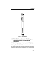
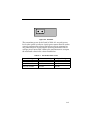
7H02-06 Fast Ethernet
SmartSWITCH™ Interface
Module User’s Guide
9031924
Notice
NOTICE
Cabletron Systems reserves the right to make changes in
specifications and other information contained in this document
without prior notice. The reader should in all cases consult
Cabletron Systems to determine whether any such changes have
been made.
The hardware, firmware, or software described in this manual is
subject to change without notice.
IN NO EVENT SHALL CABLETRON SYSTEMS BE LIABLE FOR
ANY INCIDENTAL, INDIRECT, SPECIAL, OR
CONSEQUENTIAL DAMAGES WHATSOEVER (INCLUDING
BUT NOT LIMITED TO LOST PROFITS) ARISING OUT OF OR
RELATED TO THIS MANUAL OR THE INFORMATION
CONTAINED IN IT, EVEN IF CABLETRON SYSTEMS HAS BEEN
ADVISED OF, KNOWN, OR SHOULD HAVE KNOWN, THE
POSSIBILITY OF SUCH DAMAGES.
© Copyright July 22, 1996 by:
Cabletron Systems, Inc.,
35 Industrial Way
Rochester, NH 03867-0505
All Rights Reserved
Printed in the United States of America
Order Number: 9031924 July 22, 1996
LANVIEW® is a registered trademark of Cabletron Systems, Inc.
Ethernet is a trademark of Xerox Corp.
CompuServe® is a registered trademark of CompuServe, Inc.
i
Notice
FCC NOTICE
This device complies with Part 15 of the FCC rules. Operation is
subject to the following two conditions: (1) this device may not
cause harmful interference, and (2) this device must accept any
interference received, including interference that may cause
undesired operation.
NOTE: This equipment has been tested and found to comply with
the limits for a Class A digital device, pursuant to Part 15 of the
FCC rules. These limits are designed to provide reasonable
protection against harmful interference when the equipment is
operated in a commercial environment. This equipment uses,
generates, and can radiate radio frequency energy and if not
installed in accordance with the operator’s manual, may cause
harmful interference to radio communications. Operation of this
equipment in a residential area is likely to cause interference in
which case the user will be required to correct the interference at his
own expense.
WARNING: Changes or modifications made to this device which
are not expressly approved by the party responsible for compliance
could void the user’s authority to operate the equipment.
DOC NOTICE
This digital apparatus does not exceed the Class A limits for radio
noise emissions from digital apparatus set out in the Radio
Interference Regulations of the Canadian Department of
Communications.
Le présent appareil numérique n’émet pas de bruits
radioélectriques dépassant les limites applicables aux appareils
numériques de la class A prescrites dans le Règlement sur le
ii
Notice
brouillage radioélectrique édicté par le ministère des
Communications du Canada.
VCCI NOTICE
This equipment is in the 1st Class Category (information
equipment to be used in commercial and/or industrial areas) and
conforms to the standards set by the Voluntary Control Council for
Interference by Information Technology Equipment (VCCI) aimed
at preventing radio interference in commercial and/or industrial
areas.
Consequently, when used in a residential area or in an adjacent area
thereto, radio interference may be caused to radios and TV
receivers, etc.
Read the instructions for correct handling.
iii
Notice
EXCLUSION OF WARRANTY
AND DISCLAIMER OF LIABILITY
1. EXCLUSION OF WARRANTY. Except as may be specifically
provided by Cabletron in writing, Cabletron makes no warranty,
expressed or implied, concerning the Program (including Its
documentation and media).
CABLETRON DISCLAIMS ALL WARRANTIES, OTHER THAN
THOSE SUPPLIED TO YOU BY CABLETRON IN WRITING,
EITHER EXPRESS OR IMPLIED, INCLUDING BUT NOT
LIMITED TO IMPLIED WARRANTIES OF MERCHANTABLITY
AND FITNESS FOR A PARTICULAR PURPOSE, WITH RESPECT
TO THE PROGRAM, THE ACCOMPANYING WRITTEN
MATERIALS, AND ANY ACCOMPANYING HARDWARE.
2. NO LIABILITY FOR CONSEQUENTIAL DAMAGES. IN NO
EVENT SHALL CABLETRON OR ITS SUPPLIERS BE LIABLE
FOR ANY DAMAGES WHATSOEVER (INCLUDING, WITHOUT
LIMITATION, DAMAGES FOR LOSS OF BUSINESS, PROFITS,
BUSINESS INTERRUPTION, LOSS OF BUSINESS
INFORMATION, SPECIAL, INCIDENTAL, CONSEQUENTIAL,
OR RELIANCE DAMAGES, OR OTHER LOSS) ARISING OUT OF
THE USE OR INABILITY TO USE THIS CABLETRON PRODUCT,
EVEN IF CABLETRON HAS BEEN ADVISED OF THE
POSSIBILITY OF SUCH DAMAGES. BECAUSE SOME STATES
DO NOT ALLOW THE EXCLUSION OR LIMITATION OF
LIABILITY FOR CONSEQUENTIAL OR INCIDENTAL
DAMAGES, OR ON THE DURATION OR LIMITATION OF
IMPLIED WARRANTEES IN SOME INSTANCES THE ABOVE
LIMITATIONS AND EXCLUSIONS MAY NOT APPLY TO YOU.
iv
CONTENTS
CHAPTER 1 INTRODUCTION
1.1 USING THIS MANUAL .........................................................................1-1
1.2 THE 7H02-06 MODULE..........................................................................1-2
1.2.1 Cable Type and FEPIMs................................................................1-2
1.2.2 7C03 MMAC SmartSWITCH, the 7C04 Workgroup
SmartSWITCH and the 7C04-R Workgroup SmartSWITCH...1-3
1.3 FEATURES ................................................................................................1-4
1.3.1 LANVIEW LEDs ............................................................................1-4
1.3.2 FEPIMs ............................................................................................1-5
1.3.3 Connectivity....................................................................................1-5
1.4 RELATED MANUALS ............................................................................1-6
1.5 GETTING HELP.......................................................................................1-6
CHAPTER 2 NETWORK REQUIREMENTS
2.1 FEPIM Module Specifications ................................................................2-1
2.2 FE-100FX....................................................................................................2-1
2.3 FE-100TX and Fixed RJ45 Ports..............................................................2-2
CHAPTER 3 INSTALLATION
3.1 UNPACKING THE 7H02-06 MODULE................................................3-1
3.2 INSTALLING FEPIMS.............................................................................3-1
3.3 INSTALLING/REMOVING THE 7H02-06 MODULE.......................3-3
3.3.1 Installing the 7H02-06 Module in a 7C03 MMAC
SmartSwitch....................................................................................3-3
3.3.2 Removing the 7H02-06 Module from a 7C03 MMAC
SmartSwitch....................................................................................3-5
3.3.3 Installing the 7H02-06 Module in a 7C04
or 7C04-R Chassis ..........................................................................3-6
3.3.4 Removing the 7H02-06 Module from a 7C04
or 7C04-R Chassis ..........................................................................3-8
CHAPTER 4 TROUBLESHOOTING
CHAPTER 5 TECHNICAL SPECIFICATIONS
5.1 SYSTEM RESOURCES ............................................................................5-1
5.2 STANDARDS............................................................................................5-1
v
Contents
5.3
5.4
5.5
5.6
5.7
5.8
SAFETY......................................................................................................5-1
EMI .............................................................................................................5-1
IMMUNITY...............................................................................................5-2
NETWORK INTERFACES ......................................................................5-2
SERVICE ....................................................................................................5-2
PHYSICAL ................................................................................................5-2
5.8.1 Dimensions .....................................................................................5-2
5.8.2 Weight ..............................................................................................5-2
5.8.3 Environmental ................................................................................5-3
APPENDIX A
A.1 FE-100TX ................................................................................................ A-1
A.2 FE-100FX................................................................................................. A-1
vi
CHAPTER 1
INTRODUCTION
Welcome to Cabletron Systems 7H02-06 Fast Ethernet
SmartSwitch™ Interface Module Installation Guide. This guide is a
simple reference for installing and using the 7H02-06 Module.
Before installing the module, carefully read this manual to gain a
full understanding of its capabilities.
The 7H02-06 Module is a six port Fast Ethernet module that
supports 10/100 operation in both half and full duplex. The 7H0206 Module supports auto negotiation allowing it to automatically
use the fastest link both it and the attached device are capable of.
Connectivity to the ports is provided by 5 RJ45 connectors and one
Fast Ethernet Port Interface Module (FEPIM), allowing either
Category 5 twisted pair or multimode fiber optic cabling. This
module connects to a network and the 7X00 SmartSwitch Control
Module in the 7C03, 7C04 or 7C04-R MMAC SmartSwitch via a
SmartSwitch bus.
1.1 USING THIS MANUAL
Chapter 1, Introduction, discusses the capabilities and special
features of Cabletron Systems 7H02-06 Module. This chapter also
includes a list of related manuals.
Chapter 2, Network Requirements, contains a list of available
FEPIMs and the network requirements that should be considered
before installing the 7H02-06 Module.
Chapter 3, Installation, contains instructions for installing the
7H02-06 in the 7C03 MMAC SmartSwitch, the 7C04 Workgroup
SmartSwitch or the 7C04-R Workgroup SmartSwitch.
Chapter 4, Troubleshooting, contains instructions for using
LANVIEW® (Cabletron Systems built-in diagnostic and status
monitoring system).
Chapter 5, Technical Specifications, provides detailed information
about the physical characteristics of the 7H02-06 Module.
1-1
Introduction
1.2 THE 7H02-06 MODULE
The 7H02-06 Module provides six Fast Ethernet ports via 5 RJ45
connectors and one FEPIM. The 7H02-06 Module can be installed
in:
• The 7C03 MMAC SmartSwitch
• The 7C04 Workgroup SmartSwitch Chassis
• The 7C04-R Workgroup SmartSwitch Redundant Chassis
The 7H02-06 Module has one backplane connection and six front
panel connections. The backplane connection provides power to
the 7H02-06 Module and a channel for communication with the
7X00 SmartSwitch Control Module. The six front panel ports
provide Category 5 Twisted Pair (UTP) and one user configurable
port for UTP or multimode fiber optic connectivity (through the
FEPIM).
1.2.1 Cable Type and FEPIMs
The 7H02-06 module has six front panel connectors that interface to
the 7X00 SmartSwitch through the chassis backplane. 100 Base-TX
connections are provided through 5 RJ45s; one FEPIM provides 100
Base-TX (via RJ45) or 100 Base-FX (via multimode SC).
Note: UTP operates at 10/100 Mbps, while Fiber operates at 100 Mbps.
Both UTP and Fiber are capable of half or full duplex operation.
1-2
Introduction
7H02-06
SP
Figure 1-1. 7H02-06 Module
1.2.2 7C03 MMAC SmartSwitch, the 7C04 Workgroup
SmartSwitch and the 7C04-R Workgroup
SmartSwitch
The 7H02-06 Module is designed to be installed in the 7C03 MMAC
SmartSwitch, the 7C04 Workgroup SmartSwitch or the 7C04-R
Workgroup SmartSwitch.
The modular design of the 7C03 MMAC SmartSwitch allows other
modules that support Ethernet, Fast Ethernet, ATM, FDDI, or Token
1-3
Introduction
Ring to be used with the 7H02-06 Module. These modules provide
the capability to share data without the use of external bridges or
routers.
The 7C03 MMAC SmartSwitch is a unique module that can be
installed in an MMAC Series chassis. The 7C04 Workgroup
SmartSwitch and the 7C04-R Workgroup SmartSwitch are standalone chassis that provide the same functions.
1.3 FEATURES
The 7H02-06 provides Fast Ethernet connectivity via 5 front panel
RJ45 connectors and one FEPIM, and also includes the following
features:
• LANVIEW LEDs
• FEPIMs
• Fixed connectivity ports
1.3.1 LANVIEW LEDs
The 7H02-06 Module incorporates LANVIEW - Cabletron Systems
status monitoring and diagnostic system. Should a problem arise,
such as a power failure, the LANVIEW LEDs help you diagnose the
problem.
The 7H02-06 Module incorporates the following LANVIEW LEDs:
• Transmit (TX) LED
• Receive (RX) LED
For more information about the LANVIEW LEDs and the reset
switch on the 7H02-06 Module, refer to Chapter 4, Troubleshooting.
1-4
Introduction
1.3.2 FEPIMs
The front panel connections are standard Cabletron FEPIMs.
Currently, the 7H02-06 supports the following two FEPIMs:
• FE-100TX (see Figure 1-2). The FE-100TX allows Fast Ethernet
connectivity using Category 5 Twisted Pair (UTP) cabling with
one RJ45 connector.
=
X
10
100
FE-100TX
Figure 1-2. FE-100TX PIM.
• FE-100FX (see Figure 1-3). The FE-100FX allows Fast Ethernet
connectivity using multi-mode fiber optic cabling with SC
connector.
SP FE-100FX
Figure 1-3. FE-100FX PIM.
Refer to Appendix A of this manual for the specifications for these
FEPIMs.
1.3.3 Connectivity
The 7H02-06 Module has one backplane connection and five front
panel RJ45 connections and one FEPIM connection. The backplane
connection provides power to the 7H02-06 Module and a channel
for communication with the 7X00 SmartSwitch Control Module.
The six front panel ports provide Category 5 Twisted Pair (UTP)
and/or multimode fiber optic connectivity.
1-5
Introduction
1.4 RELATED MANUALS
The manuals listed below should be used to supplement the
procedures and other technical data provided in this manual. The
procedures will be referenced, where appropriate, but will not be
repeated.
7X00 SmartSwitch Control Module User’s Guide
7H02-06 Installation Guide
7H02-06 Local Management Appendix
7C03 MMAC SmartSwitch Installation Guide
7C04 Workgroup SmartSwitch Installation Guide
7C04-R Workgroup SmartSwitch Installation Guide
1.5 GETTING HELP
If you need additional support related to the Cabletron Systems
7H02-06 Module, or if you have any questions, comments or
suggestions related to this manual, contact Cabletron Systems
Technical support:
1-6
By phone:
(603) 332-9400
By CompuServe®:
GO CTRON from any! prompt
By Internet mail:
[email protected]
By Fax:
(603) 337-3075
By BBS:
(603) 335-3358
By Mail:
Cabletron Systems, Inc.
P.O. Box 5005
Rochester, NH 03866-5005
CHAPTER 2
NETWORK REQUIREMENTS
Before installing Cabletron Systems 7H02-06 Module, review the
network requirements outlined in this chapter. All requirements
included in this chapter should be met to ensure satisfactory
performance of the 7H02-06 Module. Failure to do so may result in
unsatisfactory network performance.
Appendix A
2.1 FEPIM MODULE SPECIFICATIONS
This module uses 5 RJ45 connectors and one Fast Ethernet Port
Interface Modules (FEPIMs) to provide front panel cable
connections. The FEPIMs are user-installable. See Section
3.2 INSTALLING FEPIMS.
2.2 FE-100FX
The FE-100FX provides a multimode fiber connection, using a SC
type connector. The specifications for this device are listed in
Table 2-1.
Table 2-1. FE-100FX Specifications
Worst
Case
Budget
Typical
Value
Worst
Case
Receive
Sensitivity
-30.5 dBm
-28.0 dBm
—
—
Peak Input
Power
-7.6 dBm
-8.2 dBm
—
—
Parameter
Typical
Budget
2-1
Network Requirements
Transmitter power parameters are listed in Table 2-2.
Table 2-2. Transmitter Power Parameters
Worst
Case
Budget
Parameter
Typical
Value
Worst
Case
Typical
Budget
50/125 µm
fiber
-13.0 dBm
-15.0 dBm
13.0 dB
17.5 dB
62.5/125
µm fiber
-10.0 dBm
-12.0 dBm
16.0 dB
20.5 dB
100/140
µm fiber
-7.0 dBm
-9.0 dBm
19.0 dB
23.5 dB
Error Rate
Better than
10-10
The link distance is up to 2 kilometers on the multimode fiber-optic
cable as specified by ANSI MMF-PMD.
Note: The link distance for Full Duplex is 2km; if Full Duplex is not being
utilized, the link distance is 400 meters.
2.3 FE-100TX AND FIXED RJ45 PORTS
The FE-100TX has an RJ45 connector supporting a Category 5
Unshielded Twisted Pair (UTP) connection. The pinouts for the FE100TX and FE-100FX are listed in Table 2-3.
2-2
Network Requirements
Table 2-3. FEPIM Pinouts
Pin Number
Represents
Pin Number
Represents
1
Transmit+
5
NA
2
Transmit-
6
Receive-
3
Receive+
7
NA
4
NA
8
NA
The link distance is up to 100 meters on unshielded Category 5
twisted pair cable as specified by ANSI TP-PMD.
2-3
Network Requirements
2-4
CHAPTER 3
INSTALLATION
This chapter contains instructions for unpacking and installing the
7H02-06 Module in the 7C03, 7C04, 7C04-R MMAC SmartSwitch.
Also included in the chapter are instructions for the front panel
FEPIMs.
3.1 UNPACKING THE 7H02-06 MODULE
Unpack the 7H02-06 Module by using the following steps:
1. Carefully remove the module from the shipping box. (Save the
box and packing materials in the event the module must be
reshipped.)
2. Remove the module from the plastic bag. Observe all
precautions to prevent damage from Electrostatic Discharge
(ESD).
3. Carefully examine the module and check for damage. If damage
exists, DO NOT install the module; contact Cabletron Systems
Technical Support.
3.2 INSTALLING FEPIMS
The 7H02-06 module is shipped without an FEPIM. To install an
FEPIM, follow the procedure below:
1. Remove the module if it is installed in the 7C03 MMAC
SmartSwitch chassis (follow the procedure in Section 3.3.2.)
Note: The procedure for removing the module depends upon the chassis
(7C03,7C04 or 7C04-R) the module is installed in. See the
applicable removal procedure contained within the following pages.
2. Remove the module faceplate by removing the 3 screws on the
bottom of the module. Carefully remove the module faceplate
exposing the slot for the FEPIM (see Figure 3-1).
3-1
Installation
Ejector Tab
Ejector Tab
Screws
Figure 3-1. Module Bottom View
3. Remove the blank front cover over the FEPIM slot.
4. Install the FEPIM as shown in Figure 3-2. Ensure that the rear
connector is seated firmly before tightening the three mounting
screws.
Note: Carefully push the FEPIM straight down once it is firmly seated
onto the module.
5. Re-install the module faceplate by adding the 3 mounting
screws to the bottom of the module.
3-2
Installation
Figure 3-2. Installing an FEPIM
3.3 INSTALLING/REMOVING THE 7H02-06 MODULE
The 7H02-06 Module is installed in: the 7C03 MMAC SmartSwitch,
the 7C04 Workgroup SmartSwitch or the 7C04-R Workgroup
SmartSwitch by using the following steps and referring to the
appropriate figure.
3.3.1 Installing the 7H02-06 Module in a 7C03 MMAC
SmartSwitch
The 7H02-06 Module cannot be installed in the left most slot of the
7C03 MMAC SmartSwitch. That slot is reserved for the 7X00
SmartSwitch Controller Module.
Note: Before installing the 7H02-06 Module, attach the wrist strap
included with the module (instructions are printed on the packet).
To install the 7H02-06 Module in a 7C03 MMAC SmartSwitch,
follow the listed steps and refer to Figure 3-3.
3-3
Installation
1. Remove the blank panel covering the slot in which the module
will be installed. All other slots in the 7C03 must remain
covered to ensure proper airflow and cooling.
2. Slide the module into the slot. Make sure the printed circuit
board (PCB) is between the card guides, slides in straight, and
engages the backplane connectors properly.
3. Use a slotted screwdriver to tighten the module’s front panel
screws.
TPRMIM-20
MAC ADR
TPRMIM-20
SP
SN
Figure 3-3. Installing the 7H02-06 Module in the
7C03 MMAC SmartSwitch
3-4
Installation
3.3.2 Removing the 7H02-06 Module from a 7C03 MMAC
SmartSwitch
To remove the 7H02-06 Module from a 7C03 MMAC SmartSwitch,
follow the listed steps and refer to Figure 3-4.
Note: Before removing the 7H02-06 Module, attach the wrist strap
included with the module (instructions are printed on the packet).
1. Use a slotted screwdriver to loosen the two screws that secure
the module to the chassis.
2. Locate the two ejector tabs on the module (to the right of the
screws on the top and bottom of the module).
3. Simultaneously press down on the bottom ejector tab and press
up on the top ejector tab until the module ejects from the
backplane.
4. Grasp both ejector tabs and carefully slide the module out of
the chassis.
Screws
Ejector
Tabs
Figure 3-4. Removing the 7H02-06 Module from a 7C03 MMAC SmartSwitch
3-5
Installation
3.3.3 Installing the 7H02-06 Module in a 7C04 or 7C04-R
Chassis
To install the 7H02-06 Module in a 7C04 or 7C04-R Chassis, follow
the listed steps and refer to Figure 3-5 and Figure 3-6, respectively.
Notes: The 7H02-06 Module cannot be installed in the top slot of the
7C04 Chassis. The top slot is reserved for the 7X00 SmartSwitch
Module.
The 7H02-06 Module cannot be installed in the bottom slot in the
7C04-R Chassis. The bottom slot is reserved for the 7X00
SmartSwitch Module.
Before installing the 7H02-06 Module, attach the wrist strap
included with the module (instructions are printed on the packet).
1. Remove the blank panel covering the slot in which the module
will be installed. All other slots in the chassis must remain
covered to ensure proper airflow and cooling.
2. Slide the module into the slot. Make sure the printed circuit
board (PCB) is between the card guides, slides in straight, and
engages the backplane connectors properly.
3. Use a slotted screwdriver to tighten the module’s front panel
screws.
3-6
Installation
1
P
S
P
S
2
POWER IN
POWER OUT
OVERLOAD
FANS
3
4
Figure 3-5. Installing the 7H02-06 Module in the 7C04 Workgroup
SmartSwitch
4
3
2
X X-XXXX
-X
X X-XXXX
-X
1
Figure 3-6. Installing the 7H02-06 Module in the 7C04-R Workgroup
SmartSwitch
3-7
Installation
3.3.4 Removing the 7H02-06 Module from a 7C04 or
7C04-R Chassis
To remove the 7H02-06 Module from a 7C04 or 7C04-R Chassis,
follow the listed steps and refer to Figure 3-7 and Figure 3-8
respectively.
Note: Before removing the 7H02-06 Module, attach the wrist strap
included with the module (instructions are printed on the packet).
1. Use a slotted screwdriver to loosen the two screws that secure
the module to the chassis.
2. Locate the two ejector tabs on the module (below the screws on
the left and right ends of the module).
3. Simultaneously press left on the left ejector tab and press right
on the right ejector tab until the module ejects from the
backplane.
4. Grasp both ejector tabs and carefully slide the module out of
the chassis.
Screws
1
P
S
P
S
2
FANS
3
4
Ejector Tabs
Figure 3-7. Removing the 7H02-06 Module from the 7C04 Workgroup
SmartSwitch
3-8
Installation
4
3
2
XXX -XXX-XXX
XXX -XXX-XXX
1
Screws
Ejector Tabs
Figure 3-8. Removing the 7H02-06 Module from the 7C04-R Workgroup
SmartSwitch.
3-9
Installation
3-10
CHAPTER 4
TROUBLESHOOTING
The 7H02-06 Module uses LANVIEW, Cabletron Systems built-in
visual diagnostic and status monitoring system.
With LANVIEW LEDs the status of each transmit and receive port
on the 7H02-06 Module can be determined, at a glance. This section
discusses the function and purpose of the LEDs on the 7H02-06
Module.
Figure 4-1 shows the LANVIEW LEDs of the 7H02-06 Module.
7H02-06
SP
Transmit
Receive
Figure 4-1. The LANVIEW LEDs
4-1
Troubleshooting
Table 4-1 indicates the state of the receive port.
Table 4-1. Port Receive LEDs
LED Color
State
Green
Link, no activity, port enabled
Green (Flashing)
Link, port disabled
Yellow (Flashing)
Link, activity, port enabled (flashing to
steady-on indicates receive rate).
Red
Fault
Off
No link, port disabled
Table 4-2 indicates the state of the transmit port.
Table 4-2. Port Transmit LEDs
LED Color
4-2
State
Green (Flashing)
Data activity, port enabled (flashing to
steady-on indicates rate).
Yellow (Blinking)
Port in Standby State
Red (Flashing)
Collision (flashing to steady-on indicates
rate).
Red
Fault
Off
No activity, port enabled
CHAPTER 5
TECHNICAL SPECIFICATIONS
This chapter includes the technical specifications for Cabletron
Systems 7H02-06 module. Cabletron Systems reserves the right to
change these specifications at any time without notice.
5.1 SYSTEM RESOURCES
Internal Processor: Intel i960 running at 33 MHz
Read Only Memory: 256K bytes
CPU Memory: 8 MB
Packet Filter Rate: 750,000 packets
Packet Forward Rate: 750,000 packets
Aging Time: 5 minutes
5.2 STANDARDS
IEEE 802.1D
IEEE 802.3i 10BASE-T
5.3 SAFETY
The 7H02-06 module meets the following safety guidelines for
limitations of conducted and radiated emissions:
•
•
•
•
UL1950
CSA C22.2 No.950
EN60950
IEC 950
5.4 EMI
The 7H02-06 Module meets the requirements of:
•
•
FN55022 Class A
FCC Part 15 Class A
5-1
Technical Specifications
•
VCCI Class I
5.5 IMMUNITY
The 7H02-06 Module meets the requirements of EN50082-1
including:
•
•
•
IEC 801-2 ESD
IEC 803-1 radiated immunity
IEC 801-4 EFT/B
5.6 NETWORK INTERFACES
5 RJ45 connectors and 1 FEPIM.
5.7 SERVICE
MTBF
>200,000 hours
MTTR
<0.5 hour
5.8 PHYSICAL
5.8.1 Dimensions
31.1 D x 22.9 H x 3.1 W centimeters
(12.3 D x 9.0 H x 1.2 W inches)
5.8.2 Weight
5-2
Unit:
1.8 kg. (4 lbs.)
Shipping
4.5 kg. (10 lbs.)
Technical Specifications
5.8.3 Environmental
Operating Temperature +5° to +40° C (+41° to +104° F)
Storage Temperature
Relative Humidity
-30° to +80° C (-22° to +160° F)
5 to 95% (non-condensing)
5-3
Technical Specifications
5-4
APPENDIX A
The 7H02-06 module uses Fast Ethernet Interface Modules
(FEPIMs) to provide front panel cable connections. The FEPIMs are
user-installable. See the section ‘Installing an FEPIM’ on page 3-1.
A.1 FE-100TX
The FE-100TX is an RJ45 connector supporting Unshielded Twisted
Pair (UTP) cabling.
The slide switch on the FE-100TX determines the crossover status
of the cable pairs. If the switch is on the X side, the pairs are
internally crossed over. If the switch is on the = side, the pairs are
not internally crossed over. Figure A-1 shows the pinouts for the
FEPIM-100TX in both positions.
Position X
(crossed over)
Position =
(not crossed over)
1. TX+
2. TX3. RX+
4. NC
5. NC
6. RX7. NC
8. NC
=
x
10
100
FE-100TX
166505
1. RX+
2. RX3. TX+
4. NC
5. NC
6. TX7. NC
8. NC
Figure A-1. FE-100TX Pinouts
A.2 FE-100FX
The FE-100FX shown in Figure A-2 supports multimode fiber optic
cabling. The FE-100FX is equipped with an SC style port.
Transmitter power specifications for the FE-100FX are listed in
Table A-1 on the following page.
A-1
SP FE-100FX
Figure A-2. FE-100FX
The transmitter power levels listed in Table A-1 are peak power
levels after optical overshoot. A peak power meter must be used to
correctly compare the values given below to those measured on
any particular port. If power levels are being measured with an
average power meter, add 3 dBm to the measurement to compare
the measured values to the values listed below.
Table A-1. Transmitter Power Levels
Cable Type
Worst Case Budget
Typical Budget
50/125 µm fiber
6.0 dB
9.0 dB
62.5/125 µm fiber
9.0 dB
12.0 dB
100/140 µm fiber
15.0 dB
18.0 dB
A-2