1
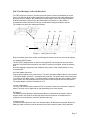
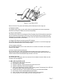
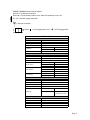
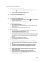
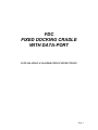
FDC
FIXED DOCKING CRADLE
WITH DATA-PORT
INSTALLATION AND OPERATING INSTRUCTIONS
Page 1
FDC Fixed Docking Cradle with Data Port:
The FDC serves the function of converting a mobile phone to have the capabilities of a fixed
phone. The Ericsson R190 mobile satellite phone when docked onto the cradle will become a
fixed phone unit. In addition, the cradle has an in-built charger, which will charge the docked
R190 and a speaker, which will give the R190 hands free functions. In other words, a
speakerphone feature allows the R190 user to talk without lifting the handset to the ear.
The operating functions are explained as follows:
(b)
(c)
(d)
(e)
(a)
Figure A – Back Panel of Cradle
Refer to the back panel of the cradle, the following connections are shown (from left to right) as:
a) Charging ON/OFF switch
The ON / OFF Charging Switch is used for turning ON/OFF the charging function only when
required. The R190 must be docked on the cradle. If charging is complete, turned the switch to
OFF.
Note that charging will stop when the handset is being used or when making a data or voice
communication.
b) Power Adapter Connector
Plug the power adapter to the power source. The end of the power adapter cable is to be inserted
in the power adapter connector to complete the connection. The power switch must be switched
on in order for the cradle to work. The power switch is located on the face of the cradle to switch
on the cradle. Also, the speakerphone can only function when the power switch is switched on.
The power adapter connector is labeled DC 12 V.
c) Voice / Data switch
The voice call / data call switch allows the FDC to operate in either voice call mode or data call
mode. The switch can be flipped left or right depending on the mode chosen.
d) Data port
The data port socket allows the data interface cable to be attached to the cradle in order to
support email or fax. Email or fax through either Personal Computer or Notebook can be
supported in communications network of satellite mode only.
e) Antenna point
The Antenna Point allows the end of the antenna cable to be attached to the cradle. Rotate the
SMA type male connector round the antenna point until the antenna cable is firmly attached.
Page 2
(g)
(h)
(i)
(j)
(f)
(k)
Figure B – Front Panel of FDC
Refer to the front of the panel; the following are the features (from left to right) as:
f) Telephone handset
The handset, when resting on the cradle, allows the speakerphone to become operational.
Otherwise, by lifting the handset, the user can talk privately.
g) Cavity for docking R190
The cavity on the center is for docking the R190. The base of the R190 should be inserted into
the wire connection at the bottom of the cavity. The R190 should then be pressed down and
clipped firmly in the cradle. (Remember to remove the stick antenna before docking the R190.
The battery should remain on the R190.)
h) Charger LED indicator and power supply LED indicator
An indicator light shows green and flickering to indicate the power is on and the charger light
shows red to indicate that the R190 is being charged.
i) Power supply push-button
On the bottom right hand corner of the cradle, there is a switch to be turned on for the power
supply for the charger.
j) Volume control knob at the side panel
On the right side of the cradle and situated near the base is the volume control knob. For
optimum voice quality on the speakerphone, the knob should be kept at half volume and “ear
volume” button on the R190 should be kept at either 4 or 5 bars.
(k) Handset Connector
On the front side of the panel, there is a connector for the handset connector. Make sure the
connector is firmly plugged in.
CARE AND MAINTENANCE
1)
2)
3)
4)
5)
6)
7)
8)
9)
Keep the FDC clean and free from dust.
Do not paint on the cradle.
Keep the cradle dry. Water and liquids will cause short circuit.
Keep the cradle from direct heat and sunlight.
Never open and attempt to repair the FDC circuits yourself. The warranty for the FDC will
no longer be valid if it has been tampered with.
Position the antenna in a secured place and safe from environmental hazards.
Do not drop or hit the antenna against any hard object.
Never coat the antenna with paint, which will reduce signal reception.
Clean the antenna every few months to prevent accumulation of dirt.
Page 3
Labels / Symbols found at the back panel:
Data Port = A data port connection
Data Call = Flip the switch to either Voice / Data Call according to your use
DC 12V = A power supply connection
= Antenna connection
Where ‘ ‘ = ON charging switch and ‘
‘ = OFF charging switch
Charge Switch
Satellite
Orbital Slot
Orbital Type
Launch Date
Frequency
Network
Dimension (mm)
Weight (g)
Colour
Power Source
Line Interface
Environment
Type
Dimension (mm)
Weight (g)
Impedance
Connector
SPECIFICATION
SYSTEM
Garuda-1
123ºE
Geosynchronous Earth Orbit (GEO)
Feb-00
Transmit
1626.5 – 1660.5 MHz
Receive
1525.0 – 1559.0 MHz
ACeS
HARDWARE
CRADLE
158x22x220
600
Black
AC Power Supply
110 – 240 VAC
Operating Voltage
12 VDC
500 mA (max)
Operating Current
Conector
RJ-11
Voice
2-Wire
Dialing
DTMF
Operating Temp.
0ºC to +60ºC
0ºC to +60ºC
Storage Temp.
ANTENNA
Outdoor
160x160x110
400
50 Ω
N-type Female
Elevation Adjustment 15º to 90º (vertical)
Mounting
Pole Size
Type
Impedance
Length
Connector to Antenna
Connector to Cradle
CABLE
RG-58 or LWR 200 coaxial
50 Ω
10.5 m
N-type male
SMA male
3/4 to 5/4 inch (to be
provided by the user)
Page 4
INSTALLING THE HARDWARE
(1)
Connecting the Antenna Cable to the FDC
a. Connect one end of the antenna cable (SMA type connector) to the connector
marked “
“ on the back panel of the cradle. Refer to Figure A.
b. Turn the connection clockwise and tighten very well.
(2)
Connecting the Telephone Handset to FDC
a. Connect the coiled-cable end of the handset to the front side of the panel as
shown in Figure A.
b. Make sure that the connector is firmly plugged in place.
(3)
Connecting the Power Adapter to FDC
a. Connect the Power Adapter cable connector marked “ DC12V” on the back panel
of the FDC. Refer to Figure A.
b. Make sure that the connector is firmly plugged in place.
(4)
Docking R190 at the Cradle
a. Remove the stick antenna from the R190.
b. Keep the battery on the R190.
c. Insert the base of the R190 into the wire connection at the bottom of the cavity.
Refer to Figure B.
d. Pressed down the R190 and clipped firmly in the cradle.
(5)
Making a Voice Call
a. Turn ON the power of the Cradle by pressing down the Power Supply Push
Button on the front panel. Refer to Figure B.
b. To use the speaker, keep the handset on the Cradle.
c. To use the handset, lift the handset from the Cradle.
d. Dial the destination number as instructed in your SIM card User’s Guide. (NOTE:
For international calls that require “+” before the country code, dialing “+” can be
done by dialing “*” twice in the telephone followed by the desired international
number.)
e. Refer to R190 User’s Manual for its operation.
f. Put the telephone handset back on hook to hang up.
(6)
Receiving a Voice Call
a. Turn ON the power of the Cradle by pressing down the Power Supply Push
Button on the front panel. Refer to Figure B.
b. You will hear a Ringing Tone in your telephone set when there’s an incoming
call.
c. To answer the call by using the speaker, keep the handset on the Cradle.
d. To answer the call by using the handset, lift the handset from the Cradle.
e. Put the telephone handset back on hook to hang up.
(7)
Making a Data Call
a. Connect the data adapter cable into the Data Port at the back panel of the
Cradle. Refer to Figure A.
b. Connect the other end of data adapter cable to the SoftGSM cable.
c. Plug the serial connector of the SoftGSM cable to the computer or laptop.
d. Flip the switch of the ‘voice call/data call’ to ‘data call’.
e. Turn ON the power of the cradle.
Page 5
TROUBLESHOOTING
Problem
Action
The Power Supply Indicator Light Does Not Come 1. Check if the Power Supply Push Button is
On
pressed down.
2. Check if the Power Adapter is connected to the
power supply.
3. Check if the Cradle is connected to the Power
Adapter.
Unable To Register With The Network
1. Check if the Antenna Cable is properly
connected to the Antenna.
2. Check if the Antenna is directed to the satellite.
The Signal Reception Is Weak
Call Always Gets Cut-off
Unable To Receive Calls
Unable To Make Calls
3. Check if the Antenna is free from any
obstructions.
4. Try to register with network manually. Refer to
your R190 User's Manual.
1. Check if the Antenna is directed to the satellite.
2. Check if the Antenna is free from any
obstructions.
3. Try to register with network manually. Refer to
your R190 User's Manual.
1. Charge the R190 battery if the battery has been
totally discharged.
2. Ensure that the signal reception is not weak.
3. Try to register with network manually. Refer to
your R190 User's Manual.
1. Check if the Power Supply Push Button is
pressed down.
2. Check if the ring volume of your telephone is
set to the proper level.
3. Try to register with network manually. Refer to
your R190 User's Manual.
1. Check if R190 phone is already registered with
the network.
2. Check if the SIM card is inserted properly in the
R190.
3. Try to register with network manually. Refer to
your R190 User's Manual.
Notes:
• If the problem persists, try to switch off the cradle unit (using Power on/off switch) and
R190 phone (using on/off switch) and turn them on again.
• If the problem still persists, bring the terminal to your nearest service center.
4/21/2003 www.tditelecom.com
Page 6