1
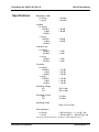
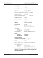
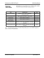
Publication No. 980673-067 Rev. B
More About
Maximum Current
Ratings
1260-43 User Manual
The front panel connector and pins are rated for 2 A per pin, with
all channels conducting full-rated current. The relays are rated at
2 A. This keeps the temperature rise within 10°C.
Definitions:
•
Max current carrying capacity
The maximum current that the relay can conduct if the relay
is not switched while voltage is applied. The maximum
current carrying capacity is affected by the size of the
conducting section of the contact at its smallest area. The
listed values are obtained from several tests in laboratories
under room-temperature conditions (21°C). The contact is
considered to be in free air. The maximum current carrying
for the 1260-43 is 2.5 A.
•
Max operating current
The current the contacts can switch while conducting,
without deteriorating. This depends on working conditions,
such as dissipated heat, cooling provisions, ambient
temperature, insulation material, etc. The maximum
operating current for the 1260-43 is 2 A.
•
Recommended continuous current
The maximum current recommended for indefinitely-long
time periods. The primary concern here is the heat
generated in the relay. This specification can be applied for
normal working conditions. The specification includes a
safety margin. However, there are restrictions in the
application of the given values. The most important
restriction is the cross-sectional area of the connecting wire,
insulation temperature range, and wire bundling. The
recommended continuous current for the 1260-43 is 2 A.
Installation
To install the 1260-43 Switching Module into a VXI mainframe
chassis, engage the printed circuit board into the grooves of the
desired chassis slot. Slide the 1260-43 into the chassis until its
connector mates with the connector on the chassis backplane.
Push firmly to fully seat the connector. Tighten the two retaining
screws at the top and bottom of the 1260-43 plug-in.
A 01T is required in the system in order for the 1260-43 to
operate. An additional VXI Switch card containing a 01T needs to
be installed in the system with the slot location to the left of the
1260-43.
Astronics Test Systems
Installation Instructions 2-11