1
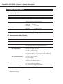
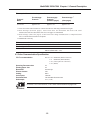
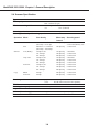
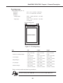
MultiPASS C530/C560 Chapter 2: Technical Reference
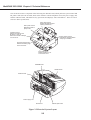
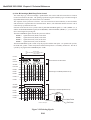
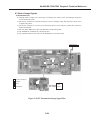
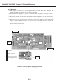
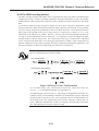
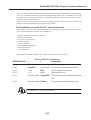
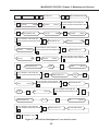
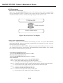
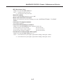
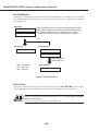
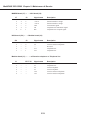
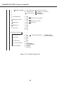
d) Color G3 Reception
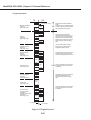
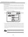
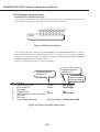
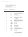
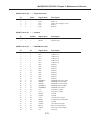
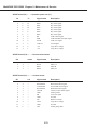
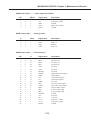
(1) Image signals received by L1, L2, pass through the hybrid circuit in the NCU, and are amplified. The
modem demodulate these images, and writes them to the DRAM.
(2) The JPEG data is converted to Lab data and then converted to RGB data.
(3) The 200 dpi RGB data is converted to 360 dpi CMYK print data.
(4) The system controller IC converts the resolution converted printer data to BJ printer head control
signals, and then sends the signals to the BJ print head, via the MPU & printer controller IC.
Simultaneously, the MPU & printer controler IC sends motor control signals to the carriage motor and
line feed motor, via the driver IC.
Carriage motor
(4)
(4)
(3)
f
(2)
(4)
e
BJ
Print head
d
b
(4)
c
(3)
g
(4)
Paper feed motor
a
MODEM IC
b
DRAM
c
System controller IC
d
SPCNT board
(1)
(1)
a
MPU
e
MPU & printer controller IC
f
Driver IC(Carriage motor)
g
Driver IC(Paper feed motor)
NCU
board
Modem board
Figure 2-23 Color G3 Reception Image Signal Flow
2-32