1
IPmux-16
TDMoIP Gateway
Installation and Operation Manual
Notice
This manual contains information that is proprietary to RAD Data Communications. No part of this
publication may be reproduced in any form whatsoever without prior written approval by RAD Data
Communications.
No representation or warranties for fitness for any purpose other than what is specifically mentioned in
this manual is made either by RAD Data Communications or its agents.
For further information contact RAD Data Communications at the address below or contact your local
distributor.
International Headquarters
RAD Data Communications Ltd.
U.S. Headquarters
RAD Data Communications Inc.
24 Raoul Wallenberg St.
Tel Aviv 69719 Israel
Tel: 972-3-6458181
Fax: 972-3-6498250
E-mail: [email protected]
900 Corporate Drive
Mahwah, NJ 07430 USA
Tel: (201) 529-1100
Toll free: 1-800-444-7234
Fax: (201) 529-5777
E-mail: [email protected]
© 2001 RAD Data Communications
Publication No. 118-200-10/01
Warranty
This RAD product is warranted against defects in material and workmanship for a period of one year
from date of shipment. During the warranty period, RAD will, at its option, either repair or replace
products which prove to be defective. For warranty service or repair, this product must be returned to
a service facility designated by RAD. Buyer shall prepay shipping charges to RAD and RAD shall pay
shipping charges to return the product to Buyer. However, Buyer shall pay all shipping charges, duties
and taxes for products returned to RAD from another country.
Limitation of Warranty
The foregoing warranty shall not apply to defects resulting from improper or inadequate maintenance
by Buyer, Buyer-supplied firmware or interfacing, unauthorized modification or misuse, operation
outside of the environmental specifications for the product, or improper site preparation or
maintenance.
Exclusive Remedies
The remedies provided herein are the Buyer’s sole and exclusive remedies. RAD shall not be liable for
any direct, indirect special, incidental, or consequential damages, whether based on contract, tort, or
any legal theory.
Regulatory Information
FCC-15 User Information
This equipment has been tested and found to comply with the limits of the Class A digital device,
pursuant to Part 15 of the FCC rules. These limits are designed to provide reasonable protection
against harmful interference when the equipment is operated in a commercial environment. This
equipment generates, uses and can radiate radio frequency energy and, if not installed and used in
accordance with the instruction manual, may cause harmful interference to the radio communications.
Operation of this equipment in a residential area is likely to cause harmful interference in which case
the user will be required to correct the interference at his own expense.
Safety Warnings
The exclamation point within a triangle is intended to warn the operator
or service personnel of operation and maintenance factors relating to the
product and its operating environment which could pose a safety hazard.
Always observe standard safety precautions during installation, operation and maintenance of this
product. Only a qualified and authorized service personnel should carry out adjustment, maintenance
or repairs to this instrument. No adjustment, maintenance or repairs should be performed by either the
operator or the user.
Telecommunication Safety
The safety status of each of the ports on IPmux-16 is declared according to EN 41003 and is detailed
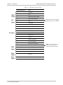
in the table below:
Safety Status
Ports
SELV
LAN, Unbalanced E1
TNV-1
Balanced E1, T1
SELV = Safety Extra-Low Voltage
TNV-1 = Telecommunications Network Voltage within the limits of SELV and subject to overvoltages
Contents
Chapter 1. Introduction
1.1 Overview .......................................................................................................... 1-1
Versions...................................................................................................................1-1
Applications.............................................................................................................1-1
Features...................................................................................................................1-3
1.2 Physical Description .......................................................................................... 1-5
Front Panel ..............................................................................................................1-6
Rear Panel ...............................................................................................................1-6
1.3 Functional Description ...................................................................................... 1-6
Operation Modes ....................................................................................................1-7
Testing.....................................................................................................................1-7
Timing Modes..........................................................................................................1-7
Frame Format ..........................................................................................................1-9
Packet Delay Variation...........................................................................................1-11
PDVT (Jitter) Buffer ................................................................................................1-12
Ethernet Throughput..............................................................................................1-13
Round Trip Delay ..................................................................................................1-14
Throughput Limitations and CAC ...........................................................................1-15
1.4 Technical Specifications .................................................................................. 1-16
E1 Modules ...........................................................................................................1-16
T1 Modules ...........................................................................................................1-16
Ethernet Modules ..................................................................................................1-17
Chapter 2. Installation
2.1 Introduction ...................................................................................................... 2-1
2.2 Site Requirements and Prerequisites.................................................................. 2-1
2.3 Package Contents.............................................................................................. 2-2
Power Cable ............................................................................................................2-2
2.4 Equipment Needed........................................................................................... 2-2
2.5 Installation and Setup........................................................................................ 2-4
Setting Jumpers........................................................................................................2-4
Connecting Interfaces and Cables.............................................................................2-4
Chapter 3. Operation
3.1 Introduction ....................................................................................................... 3-1
3.2 Front Panel Controls, Connectors, and Indicators ............................................... 3-1
3.3 Operating Instructions ........................................................................................ 3-2
Turning IPmux-16 On – Without Control Terminal...................................................3-2
Turning IPmux-16 On – With Control Terminal........................................................3-3
Turning IPmux-16 Off..............................................................................................3-4
3.4 Getting Started ................................................................................................... 3-4
3.5 Menu Operations............................................................................................... 3-5
Navigating ...............................................................................................................3-5
Main Menu..............................................................................................................3-7
IPmux-16 Installation and Operation Manual
i
Table of Contents
3.6 Configuring System Parameters .......................................................................... 3-7
Viewing System Information.....................................................................................3-7
3.7 Configuring IPmux-16 ...................................................................................... 3-10
General Configuration............................................................................................3-11
Time Slots Configuration ........................................................................................3-32
Bundle Connection Configuration ..........................................................................3-34
Setting VLAN and IP Support .................................................................................3-36
Viewing Configuration Summary ............................................................................3-37
Monitoring System Performance ............................................................................3-38
Bundle Connection Status ......................................................................................3-44
Chapter 4. Troubleshooting and Diagnostics
4.1 Error Detection ................................................................................................. 4-1
Front Panel LEDs .....................................................................................................4-1
Working with the Alarm Buffer.................................................................................4-1
4.2 Troubleshooting ................................................................................................ 4-3
4.3 Diagnostic Tests ................................................................................................ 4-4
External Loop ..........................................................................................................4-4
Internal Loop ...........................................................................................................4-4
T1 FDL Support .......................................................................................................4-5
T1 PRM Support ......................................................................................................4-5
Appendix A. Boot Sequence for Downloading Software
Appendix B. SNMP Management
Appendix C. Telnet
Appendix D. TFTP Download Procedures
List of Figures
1-1. Multiplexing Voice and Data over Fast/Giga Ethernet Trunk....................................... 1-1
1-2. IP Based Metropolitan Area Network......................................................................... 1-2
1-3. IPmux-16 3-D View .................................................................................................. 1-5
1-4. IPmux-16 Point-to-Point Application ......................................................................... 1-6
1-5. Grooming of Timeslots from Remote Sites into a Single E1/T1 Port at Central Site..... 1-6
1-6. IPmux-16 in Loopback Timing Mode......................................................................... 1-8
1-7. IPmux-16 in Adaptive Timing Mode .......................................................................... 1-9
1-8. TDMoIP Frame Structure........................................................................................... 1-9
1-9. VLAN Tag Format.................................................................................................... 1-11
1-10. Packet Delay Variation .......................................................................................... 1-12
2-1. Null Cable (CBL-DB-9/DB-9/NULL) Pin Shorts .......................................................... 2-3
2-2. IPmux-16 Front Panel................................................................................................ 2-4
2-3. IPmux-16 Rear Panel................................................................................................. 2-4
ii
IPmux-16 Installation and Operation Manual
Table of Contents
3-1. IPmux-16 Front Panel LEDs ....................................................................................... 3-1
3-2. IPmux-16 Rear Panel Switch...................................................................................... 3-1
3-3. IPmux-16 Terminal Menu Tree.................................................................................. 3-6
3-4. Main Menu ............................................................................................................... 3-7
3-5. System Menu ............................................................................................................ 3-8
3-6. General Information Window.................................................................................... 3-8
3-7. The Event Log Window ............................................................................................. 3-9
3-8. Logfile Events – Sample Menu ................................................................................... 3-9
3-9. Ping Dialog Box....................................................................................................... 3-10
3-10. Configuration Menu .............................................................................................. 3-11
3-11. General Configuration Menu ................................................................................. 3-11
3-12. The Management Configuration Menu ................................................................... 3-12
3-13. The Community Window ...................................................................................... 3-12
3-14. User Port Configuration Menu............................................................................... 3-13
3-15. The Manager List Window..................................................................................... 3-14
3-16. Default Gateway Menu ......................................................................................... 3-15
3-17. The Alarms Trap Mask Window............................................................................. 3-16
3-18. The ASCII Terminal Configuration Menu ............................................................... 3-17
3-19. Time/Date Update Menu ...................................................................................... 3-18
3-20. The Software Download Upload Window ............................................................. 3-18
3-21. Download/Upload Using X-Modem Window ........................................................ 3-19
3-22. Download/Upload Using TFTP Window................................................................ 3-20
3-23. View Transfer Status Window................................................................................ 3-21
3-24. Reset Default Warning .......................................................................................... 3-22
3-25. File System Menu .................................................................................................. 3-22
3-26. Physical Layer Configuration Menu........................................................................ 3-24
3-27. LAN Physical Layer Configuration Menu................................................................ 3-24
3-28. E1/T1 Physical Layer Configuration Menu.............................................................. 3-26
3-29. E1 Physical Layer Configuration Menu................................................................... 3-26
3-30. T1 Physical Layer Configuration Menu.................................................................... 3-29
3-31. Time Slots Configuration Menu ............................................................................. 3-33
3-32. Bundle Connection Configuration ......................................................................... 3-34
3-33. System Configuration Menu .................................................................................. 3-36
3-34. Configuration Summary Screen ............................................................................. 3-37
3-35. Performance Monitoring Menu.............................................................................. 3-38
3-36. E1/T1 Statistics Menu ............................................................................................ 3-39
3-37. LAN Statistics Menu .............................................................................................. 3-43
3-38. IP Channel Status Menu ........................................................................................ 3-45
4-1. External Loop ............................................................................................................ 4-4
4-2. Internal Loop............................................................................................................. 4-5
IPmux-16 Installation and Operation Manual
iii
Table of Contents
List of Tables
1-1.
1-2.
1-3.
1-4.
1-5.
Ethernet Frame Structure......................................................................................... 1-10
UDP Source Port as Destination Voice Port ............................................................. 1-11
Ethernet Throughput – Unframed E1 ....................................................................... 1-13
Ethernet Throughput – Unframed T1....................................................................... 1-14
System Usage for TDM Bytes per Frame .................................................................. 1-15
2-1.
2-2.
2-3.
2-4.
Null Cable Pinout Connections.................................................................................. 2-3
E1/T1 Port Connectors Pinout.................................................................................... 2-5
Ethernet Port Pinout .................................................................................................. 2-5
Alarm Connector Pinout ............................................................................................ 2-6
3-1.
3-2.
3-3.
3-4.
3-5.
IPmux-16 System Indicators and Switches ................................................................. 3-2
IPmux-16 Alarms..................................................................................................... 3-16
E1/T1 Alarms and Statistics ...................................................................................... 3-40
LAN Statistics........................................................................................................... 3-44
IP Channel Status .................................................................................................... 3-45
4-1. Event Types ............................................................................................................... 4-2
4-2. IPmux-16 Troubleshooting Chart............................................................................... 4-3
iv
IPmux-16 Installation and Operation Manual
Chapter 1
Introduction
1.1 Overview
IPmux-16 is a modular TDMoIP gateway. IPmux-16 modules enable up to 16 E1
or T1 circuits to be extended over IP networks. The device converts the data
stream coming from the E1 or T1 ports into configurable-sized IP packets that are
transported over the Ethernet port and vice versa. IPmux-16 offers end-to-end
synchronization for TDM applications and large buffers, to compensate for the
delay variation inserted by the network. The device can be used to extend E1 or
T1 services over high speed IP/Ethernet backbones for both Metropolitan Area
Network and corporate applications. IPmux-16 can be managed locally via an
ASCII terminal or remotely via Telnet or RADview (RAD’s SNMP-based network
management application).
Versions
IPmux-16 with an E1 interface:
4, 8 12 or 16 ports
Balanced line with an RJ-45 connector
Unbalanced line with a mini-coaxial connector
IPmux-16 with a T1 interface:
4, 8 12 or 16 ports
Balanced line with an RJ-45 connector
Applications
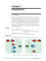
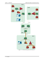
Two typical IPmux-16 applications are shown in Figure 1-1 and Figure 1-2.
PBX
IPmux-16
IPmux-16
100BaseT
PBX
100BaseT
Router
1 Gbps
Gigabit Ethernet
Switch
Gigabit Ethernet
Switch
Workstation
Workstation
Router
Workstation
Figure 1-1. Multiplexing Voice and Data over Fast/Giga Ethernet Trunk
Overview
1-1
IPmux-16 Installation and Operation Manual
Chapter 1 Introduction
Site A
PBX
Site B
Telephone
Switch
NxE1/T1
Links
IPmux-16
PBX
NxE1/T1
Links
PBX
Router
IPmux-4
Ethernet
Switch
Ethernet
Switch
IPmux-16
Telephone
Switch
Workstation
PBX
Workstation
100BaseT
100BaseT
Gigabit
Ethernet
Switch
Gigabit
Ethernet
Switch
Giga Ethernet
Backbone
MAN
Gigabit
Ethernet
Switch
100BaseT
Site C
Ethernet Switch
IPmux-16
Workstation
Router
E1/T1
PBX
NxE1/T1 Links
E1/T1
PBX
Figure 1-2. IP Based Metropolitan Area Network
1-2 Overview
IPmux-16 Installation and Operation Manual
Chapter 1 Introduction
Features
Management
IPmux-16 can be managed via a local terminal, Telnet, or via RADview, RAD’s
Network Management system. IPmux-16 has an RJ-45 port for the local terminal
connection for monitoring and control. Software upload and download and
configuration can be performed via the local terminal or via RADview.
T1
T1 ports and framers comply with ANSI T1.403 standards. The T1 jitter
performance is according to G.824, TR-62411. The T1 framers support
pass-through, SF, ESF and CAS. Integral LTU/CSU can be enabled for line
protection and long haul options. FDL and transmit PRM for T1/ESF are also
supported.
E1
E1 ports comply with G.703 and G.823 standards. E1 framers comply with G.704.
The E1 framers support pass-through, framed, CRC4 MF and CAS MF framing.
Integral LTU/CSU can be enabled for line protection and long haul options.
IP
The data stream coming from the E1 or T1 ports into IP frames is converted and
transferred over the Fast Ethernet port and vice versa.
The TDM bytes are encapsulated in a UDP frame that runs over IP and over
Ethernet.
The number of TDM bytes in an IP frame is configurable for throughput / delay
tradeoff.
A single IP address should be set per device (Host IP). A destination IP address can
be configured for each bundle (see Multibundling, below). IP ToS field support can
be configured for IP Level Priority.
Ethernet
IPmux-16 has a half/full duplex, 10/100 Ethernet port for LAN connectivity.
Each E1/T1 module includes a single, standard 10/100BaseT port with
auto-negotiation support, which provides the uplink to the network. If
auto-negotiation is disabled, IPmux-16 can be configured to any of the following:
•
100BaseT – full duplex
•
100BaseT – half duplex
•
10BaseT – full duplex
•
10BaseT – half duplex.
Half duplex operation in IPmux-16 is not recommended because collisions and
backoffs cause large delay variation and may exceed the delay variation buffer
Overview
1-3
IPmux-16 Installation and Operation Manual
Chapter 1 Introduction
tolerance at the receiving end, causing buffer underflows and errors to occur.
IPmux-16 supports VLAN tagging and priority.
Mode of Operation
IPmux-16 can operate in three different modes:
•
Unframed full E1/T1 over UDP over IP over Ethernet
•
Fractional E1/T1 over UDP over IP over Ethernet
•
Fractional with CAS over UDP over IP over Ethernet.
Multibundling
A bundle is a group of timeslots originating from a specific E1 or T1 channel. Up to
31 bundles per E1 channel and 24 bundles per T1 channel can be defined for
transport over the network. Each bundle can contain 1 to 24/31 timeslots
(T1/E1 respectively).
Two network topologies are supported:
•
Star (point-to-multipoint): Multiple remote locations transport one bundle
each to a central site which is capable of grooming the bundles into its E1 or
T1 channel.
•
Mesh: Any-to-any connectivity is supported at the bundle (DS0) level.
Internal Cross Connect
IPmux-16 allows an internal cross connect of bundles between its E1/T1 ports.
QoS
QoS support:
•
Labeling IP level priority (ToS)
•
VLAN tagging and priority labeling according to IEEE 802.1 p&q
The user can configure the ToS (Type of Service) of the outgoing IP packets. This
allows an en-route layer-3 router or switch, which supports ToS, to give higher
priority to IPmux-16 traffic for delay-sensitive and secure applications. IPmux-16
allows you to configure the WHOLE ToS byte field, since different vendors may
use different bits to tag packets for traffic prioritization. This also enables you to
work according to various RFC definitions (for example RFC 2474, RFC 791). The
user can also configure VLAN priority bits for Level 2 Priority.
Timing
Available timing modes are:
1-4 Overview
•
Loopback
The E1 or T1 Transmit clock is derived from the E1/T1 Receive clock.
•
Adaptive
In this mode, the E1 or T1 TX clock is regenerated using the Adaptive method.
In this method, the fill level of the buffer receiving packets is monitored. If the
IPmux-16 Installation and Operation Manual
Chapter 1 Introduction
buffer begins to overfill, the regenerated clock frequency increases to avoid
overflow. If the buffer begins to empty, the Receive clock decreases to avoid
underflow.
•
Internal Clock
In this mode, the Transmit (TX) clock is received from an internal oscillator.
This mode is useful for testing and diagnostic purposes.
Standards
G.703, G.704, G.706, G.823,
ANSI T1.403,
TR-AT&T62411, G.824, IEEE 802.3, IEEE 802.3D, 802.1 p&q
EMC Class B compliance – EN 55022 Class B
General
IPmux-16 is a 1.5U high easy to install standalone unit.
A rack mount option is available.
IPmux-16 can be ordered with dual redundant power supplies (two AC or two DC
modules).
1.2 Physical Description
IPmux-16 is a 1.5U high, easy-to-install standalone unit. A rack mount option is
available.
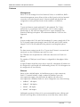
Figure 1-3. IPmux-16 3-D View
Physical Description
1-5
IPmux-16 Installation and Operation Manual
Chapter 1 Introduction
Front Panel
The control port and indicator LEDs are located on the front panel of IPmux-16.
For further details see Chapter 2.
Rear Panel
Fuses, power supplies, the dry contact connector, and interface connectors are
located on the rear panel of IPmux-16. For further details see Chapter 2.
1.3 Functional Description
IPmux-16 modules support E1 or T1 TDM interfaces. The E1 and T1 modules have
either four or eight ports. Each bundle (group of timeslots) can be transmitted to a
predefined destination bundle (see the following figure). IPmux-16 supports ICMP
(ping), and generates ARP in case of unknown next hop MAC addresses, answers
ARP requests, and supports 802.3 Ethernet format.
Configuration and management are provided via the IPmux-16 local terminal,
Telnet application or SNMP such as RADview, RAD’s Network Management
System.
E1/T1 Port 2
IP over
Ethernet
E1/T1 Port 1
E1/T1 Port 2
IPmux-16
IPmux-16
E1/T1 Port 1
IPmux-16
Figure 1-4. IPmux-16 Point-to-Point Application
Sub E1/T1
IPmux-4
IPmux-1
E1/T1 Line 1
E1/T1 Line 2
E1/T1 Line 16
IP over
Ethernet
IPmux-16
IPmux-1
IPmux-16
Sub E1/T1
Figure 1-5. Grooming of Timeslots from Remote Sites into a
Single E1/T1 Port at Central Site
1-6 Functional Description
Sub E1/T1
Sub E1/T1
IPmux-16 Installation and Operation Manual
Chapter 1 Introduction
Bundles composed of several timeslots (E1: 1-31, T1: 1-24) can be defined. Each
bundle can be connected to a different destination bundle anywhere on the
network.
Up to 496 sub-E1 or 384 sub-T1 remote bundles can be attached to one central
IPmux-16. Multibundling enables concentrating many remote sites with few
timeslots to the same TDM channel at the central site. A mesh topology
application, in which the bundles at each site are defined to connect to several
sites, is also supported.
Operation Modes
IPmux-16 operation modes are:
•
Unframed
•
Fractional
•
Fractional with CAS
Unframed
In the transparent mode, the incoming bit stream from each port (regardless of
framing) is converted into IP over Ethernet frames. This option provides clear
channel end-to-end service.
Fractional
In the fractional mode, the incoming bit stream is regarded as a sequence of
nx64 Kbps channel groups (according to framing). Each predefined group of
channels is converted into a structure block. The structure block is packetized into
IP frames and transmitted.
This mode allows transmission of several selected time slots and not the whole
E1/T1 as in transparent mode.
Fractional with CAS
In the fractional-with-CAS mode, the structure block (as described under
Fractional Operation Modes, above) also includes Channel Associated Signaling
(CAS).
Testing
Diagnostic capabilities include E1/T1 local and remote loopback tests for rapid
location of faults. Any of the E1/T1 ports can be looped locally toward the line, or
toward the remote end (see Chapter 4 for more information).
Timing Modes
The E1/T1 Transmit (TX) clock can operate in several timing modes to provide
maximum flexibility for connecting the IPmux-16 E1/T1 interface.
The available timing modes are:
•
Loopback: The E1 or T1 Transmit clock is derived from the E1/T1 Receive
clock.
Functional Description
1-7
IPmux-16 Installation and Operation Manual
Chapter 1 Introduction
•
Adaptive: In this mode, the E1 or T1 Tx clock is regenerated using the
Adaptive method. In this method, the fill level of the buffer receiving packets is
monitored. If the buffer begins to overfill, the regenerated clock frequency
increases to avoid overflow. If the buffer begins to empty, the clock decreases
to avoid underflow.
•
Internal Clock: In this mode, the Transmit (Tx) clock is received from an
internal oscillator. This mode is useful for testing and diagnostic purposes.
Each of the clocks must be configured correctly on both the Receive and Transmit
ends to ensure proper operation and prevent pattern slips.
The following paragraphs describe typical timing schemes and their correct timing
mode settings in order to achieve end-to-end synchronization.
External Network Timing
When an external network is used to synchronize the E1/T1 devices, all the
IPmux-16 units should be configured to work in loopback mode (see the following
illustration). This topology enables any-to-any connectivity; as in the following
illustration, all three IPmux-16s have direct E1/T1 connectivity. In this timing
configuration both mesh and star bundle connection topologies are supported.
Clock from External Distribution Network
E1/T1
E1/T1
E1/T1
E1/T1
E1/T1 Device
IP over
Ethernet
IPmux-16 LBT Mode E1/T1 Device
IPmux-16
E1/T1
LBT Mode
IPmux-16
E1/T1
LBT Mode E1/T1 Device
Figure 1-6. IPmux-16 in Loopback Timing Mode
Single Source Clock Network
When a common clock is not available on all the ends of the network:
•
E1/T1 Device Configuration:
One of the E1/T1 devices connected to the IPmux-16 should work as the
master clock while the others work in loopback timing.
•
IPmux-16 Configuration:
The IPmux-16 E1/T1 ports connected to the master clock E1/T1 device work in
loopback timing, while the far-end IPmux-16s work in Adaptive mode.
1-8 Functional Description
IPmux-16 Installation and Operation Manual
Note
Chapter 1 Introduction
When there are several bundles from different sources at the same E1/T1 port, the
bundle that will be used for adaptive clock regeneration for the port is the first
bundle of every port. For example (E1): Bundle number 1 for port 1, bundle number
32 for port 2, bundle number 63 for port 3, bundle number 94 for port 4, etc.
In this mode the regenerated clock is subject to network Packet Delay Variation and
may not comply with jitter and wander specifications.
Adaptive Mode
E1/T1
Loopback Timing Mode
E1/T1
E1/T1
Master Clock
Source Device
IP over
Ethernet
E1/T1
IPmux-16
Adaptive Mode
IPmux-16
Remote Loopback
Timing Devices
E1/T1
IPmux-16
E1/T1
Figure 1-7. IPmux-16 in Adaptive Timing Mode
Frame Format
The Ethernet frame sent by the IPmux-16 is a UDP datagram which transfers E1/T1
payload bytes over IP over Ethernet (UDP payload + UDP header + IP header +
Ethernet header).
The UDP payload size is equal to TDM bytes per frame (TDM bytes/frame
configuration).
The illustration below specifies the structure of the different headers, special fields,
and the payload in the Ethernet packet.
MAC
IP
UDP
Payload
Figure 1-8. TDMoIP Frame Structure
Functional Description
1-9
IPmux-16 Installation and Operation Manual
Chapter 1 Introduction
Table 1-1. Ethernet Frame Structure
MAC
Layer
LLC
Layer
IP Layer
UDP
Layer
Data
Layer
MAC
Layer
Field length (bytes)
Field
7
Preamble
1
SFD
6
Destination MAC Address
6
Source MAC Address
2
Type
1
Vers/HLEN
1
Service Type
2
Total Length
2
Identification
1
Flags/Fragment Offset (most)
1
Fragment Offset (least)
1
Time to Live
1
Protocol
2
Header Checksum
4
Source IP Address
4
Destination IP Address
2
UDP Source Port
2
UDP Destination Port
2
UDP Message Length
2
UDP Checksum
...
4
1-10 Functional Description
Payload
CRC
IEEE 802.1p&q VLAN Tagging
(additional 4 bytes if enabled)
Note: The UDP source port
field is used to transfer a
destination bundle number.
IPmux-16 Installation and Operation Manual
Chapter 1 Introduction
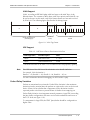
VLAN Support
VLAN, according to IEEE 802.1p&q, adds four bytes to the MAC layer of the
Ethernet frame. The contents of these bytes, MAC layer priority and VLAN ID, can
be set by the user. In this mode, only VLAN format frames are sent and received
by IPmux-16. The following figure describes the VLAN tag format.
81
00
8
802.1D Tag Protocol Type
(802.1QTagType)
6
VID
CFI = 0
user_priority
5
4
1
Priority
8
1
VLAN ID
Figure 1-9. VLAN Tag Format
UDP Support
Table 1-2. UDP Source Port as Destination Voice Port
Field Length (Bits)
Field Description
Value
2 bytes
UDP Source Port*
2 – 497d
2 bytes
UDP Destination Port
2142d
* The MSB of this field can be either 1 or 0 for inband end-to-end proprietary signaling.
Note
The UDP Source Port field is used for destination voice bundle indication.
For example, if the destination is:
Bundle 1 – 02, Bundle 2 – 03, Bundle 3 – 04, Bundle 4 – 05, etc.
For more information about VLAN tagging, see IEEE Std 802.1 p&q.
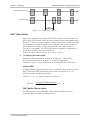
Packet Delay Variation
Packets are transmitted at set intervals. Packet Delay Variation is the maximum
deviation from the nominal time the packets are expected to arrive at the far end
device. IPmux-16 has a buffer that compensates for the deviation from the
expected packet arrival time to prevent IPmux-16 buffers from emptying out.
Packet Delay Variation is an important network parameter. Large PDV (exceeding
the jitter buffer configuration) will cause receive buffer underflows and errors at
the E1/T1 level (see Figure 1-10).
To compensate for large PDV, the PDVT (jitter) buffer should be configured to a
higher value.
Functional Description
1-11
IPmux-16 Installation and Operation Manual
Chapter 1 Introduction
Packets Leaving IPmux-16
t
Packets Arriving
t
PDV
Figure 1-10. Packet Delay Variation
PDVT (Jitter) Buffer
IPmux-16 is equipped with a Packet DVT (Delay Variation Tolerance) buffer. The
PDVT buffer or jitter buffer is filled by the incoming IP packets and emptied out to
fill the E1/T1 stream. The buffer begins to empty out only after it is half full in order
to compensate for packet starvation from the Ethernet side. The time it takes for
half of the buffer to empty out is the maximum DVT time. Delay Variation
Tolerance is configurable. The PDVT (jitter) buffer is designed to compensate for
packet delay variation caused by the network.
It supports a delay variation of up to E1: 32 ms, T1: 24 ms.
➤
To configure jitter buffer depth:
Estimated or Measured PDV introduced by the network + intrinsic PDV
(if it exists) introduced by the module as a result of configuring the
TDM bytes / frame > 48 (see explanation of calculating intrinsic PDV, below).
Intrinsic PDV
If TDM bytes/frame is greater than 48, there is an intrinsic delay variation (intrinsic
PDV). The intrinsic PDV introduced by the module is a function of n>1 in
TDM bytes/frame configuration as follows:
I.PDV (ms) = ((n – 1) x 1000) / (frames per second × n)
Where n =
configured TDM bytes/frame
(n=1 – 8).
48
PDVT Buffer Effect on Delay
The PDVT buffer is on the TDM path. This means that it adds to the total
end-to-end delay (see delay calculation, below).
1-12 Functional Description
IPmux-16 Installation and Operation Manual
Chapter 1 Introduction
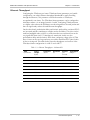
Ethernet Throughput
Configuring the TDM bytes per frame (TDM bytes/frame) parameter, per bundle
configuration, can reduce Ethernet throughput (bandwidth or traffic travelling
through the Ethernet). This parameter controls the number of TDM bytes
encapsulated in one frame. The TDM bytes/frame parameter can be configured to
nX48 bytes where n is an integer between 1 and 8. Configuring TDM bytes/frame
to a higher value reduces the IP/Ethernet overhead segment of the total packet and
thus can significantly reduce the total Ethernet throughput.
On the other hand, packetization delay and intrinsic packet delay variation (PDVT)
are increased and this contributes to a higher end-to-end delay. This effect can be
small and negligible when a full E1 (or many timeslots) are transferred but can be
very significant when few E1/T1 timeslots are transferred. In this case, the
packetization delay and the intrinsic PDV when configuring a large value of TDM
bytes / frame can be very large and may exceed the maximum PDVT (jitter) buffer
on the receiving end. The tables below show the throughput as a function of the
TDM bytes/frame configuration for a full E1 and a full T1.
Table 1-3. Ethernet Throughput – Unframed E1
TDM
bytes/frame
Frame
Length
(bytes)
Overhead
(bytes)
Overhead
(%)
Packets
(per
second)
Throughput
(Mbps)
48
94
46
96
5447
4.1
96
142
46
48
2724
3.1
144
190
46
32
1816
2.76
192
238
46
24
1362
2.6
240
286
46
19
1089
2.5
288
334
46
16
908
2.43
336
382
46
14
778
2.38
384
430
46
12
681
2.34
Functional Description
1-13
IPmux-16 Installation and Operation Manual
Chapter 1 Introduction
Table 1-4. Ethernet Throughput – Unframed T1
➤
TDM
bytes/frame
Frame
length
(bytes)
Over head
(bytes)
Over head
(%)
Packets
(per
second)
Throughput
(Mbps)
48
94
46
96
4107
3.08
96
142
46
48
2054
2.32
144
190
46
32
1369
2.07
192
238
46
24
1027
1.95
240
286
46
19
821
1.87
288
334
46
16
685
1.82
336
382
46
14
587
1.78
384
430
46
12
513
1.76
To calculate Ethernet throughput and intrinsic PDV as a function of
TDM bytes/frame:
Ethernet load (bps) = [(frame overhead (bytes) + TDM bytes/frame) × 8] × frames/second
Frame overhead = Ethernet overhead + IP overhead = 46 bytes
Frame/second =
unframed:
framed:
5447/n for a full E1
4107/n for a full T1
8000Xk / (46.875 x n)
Where k = number of assigned timeslots
Where n =
TDM bytes/frame
48
Round Trip Delay
The voice path round-trip delay, which is a function of all connections and
network parameters, is calculated for E1/T1 as follows:
RTDelay(µs) = 2 x (
48 × n
x 125 (µs) + PDVT buffer (µs) +500 (µs))+ Network round trip delay
NTS
Where n =
TDM bytes/frame
48
Where NTS = number of timeslots assigned
in unframed E1 interface = 32
T1 interface = 24
1-14 Functional Description
IPmux-16 Installation and Operation Manual
Chapter 1 Introduction
End-to-End Alarm Generation
An end-to-end alarm generation mechanism exists in the IPmux-16 to facilitate the
following alarms:
Unframed
AIS will be transmitted toward the near-end PBX in event of:
• Far-end LOS, AIS
• PDVT underflow/overflow.
Framed
Timeslot / CAS configurable alarm pattern will be transmitted
toward the near-end PBX in event of:
• Far-end LOS, LOF, AIS
• PDVT underflow/overflow.
Throughput Limitations and CAC
Ethernet port throughput of IPmux-16 is limited to a number (pps) that is smaller
than the number (pps) that should be transmitted when all 16 E1/T1 channels are
active with 48 bytes per frame. To prevent configurations that will exceed this
limit, a CAC mechanism exists and will prevent adding connections as soon as the
limit is exceeded. The mechanism also monitors and displays current system
performance optimization (percentage of budget in use).
Table 1-5. System Usage for TDM Bytes per Frame
TDM Bytes/Frame
System Resources Consumption per Timeslot
48
0.39%
96
0.2145%
144
0.1521%
192
0.1209%
240
0.1014%
288
0.0897%
336
0.0858%
384
0.078%
Functional Description
1-15
IPmux-16 Installation and Operation Manual
Chapter 1 Introduction
1.4 Technical Specifications
E1 Modules
E1 Port
E1
Framing
Ports
Up to 16
Compliance
ITU-T Rec. G.703, G.706, G.732, G.823
Connector
Balanced: RJ-45 8 pin
Unbalanced: TBNC 75Ω (an external adapter cable from
TBNC to BNC is required)
Data Rate
2.048 Mbps
Line Code
HDB3
Line Impedance
Balanced: 120Ω; Unbalanced: 75Ω
Signal Levels
Receive: 0 to –27 dB with LTU
0 to –10 dB without LTU
Transmit Balanced: ±3V ±10%
Transmit Unbalanced: ±2.37V ±10%
Jitter Performance
ITU-T G.823 standard
External Adapter
Cable
TBNC to BNC required for unbalanced interfaces
Compliance
G.704, G.706
Framing
Passthrough, CRC4 MF, CAS MF
Signaling
CAS, CCS (transparent)
Ports
Up to 16
Compliance
ANSI T1.403, ITU-T Rec. G.703
Connector
RJ-45, 8 pin
Data Rate
1.544 Mbps
Line Code
B8ZS, B7ZS, AMI
Line Impedance
Balanced: 100Ω
Signal Levels
Receive: 0 to –27 dB
Transmit: 0 dB, –7.5 dB, –15 dB, –22.5 with CSU
±2.7V ± 10%, adjustable, measured in range
0 to 655 feet without CSU
Jitter Performance
AT&T TR-62411, G.824 standards
T1 Modules
T1 Port
1-16 Technical Specifications
IPmux-16 Installation and Operation Manual
T1
Framing
Chapter 1 Introduction
Compliance
ANSI T1.403
Framing
Passthrough, SF, ESF
Signaling
CAS (bit robbing), CCS (transparent)
Local
Terminal Mode
and
Control Baud Rate
Interface Connector
RS-232 over RJ-45 (adapter cable to DB-15 supplied)
Dry
Contact
Alarm
Connector
DB-9
Contacts
30V 2A
Compliance
IEEE 802.3, 802.3u, Ethernet, 802.1 p&q
Connector
RJ-45, 8 pin
Ports
1
Data Rate
10 Mbps or 100 Mbps, full or half duplex
Range
Up to 100m over UTP Category 5 cables
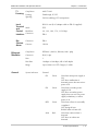
System Indicators
General:
Ethernet
Modules
General
DTE
9.6, 19.2, 38.4, 57.6, 115.2 kbps
DB-9
PS1
Green
ON when main power supply is
OK
OFF when malfunction is
detected, power does not exist or
power is off.
PS2
Green
ON when secondary power
supply is OK
OFF when secondary power
supply does not exist (no power
supply redundancy) or when
power is off
RDY
Green
ON when self-test is successfully
completed
OFF during self-test
BLINKS when self-test fails
ALM
Red:
ON when a Minor alarm is
detected
OFF when no alarms are
detected
Technical Specifications
1-17
IPmux-16 Installation and Operation Manual
Chapter 1 Introduction
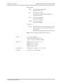
Ethernet Port:
LINK
OFF when line is not active
ON when line is OK
ACT
OFF when no activity
ON when a frame is being transmitted or
received on the line
FDX
OFF when half duplex
ON when full duplex
100M
OFF when 10 MHz
ON when 100 MHz
E1/T1 Port:
SYNC
ON when the port is synchronized (no alarm)
OFF when signal loss, LOF or AIS is detected
(local alarm)
BLINKS when RDI is detected (remote alarm)
Note: All LEDs are green and ON after power-up.
Power
1 or 2 power supplies
40W, 100 to 240 VAC, 50/60 Hz
–36 to –72 VDC (–48 VDC nominal)
Physical
Height 6.6 cm / 2.55 in (1.5U)
Width 43.2 cm / 19 in
Depth 35 cm / 13.78 in
Weight 4.0 kg / 8.8 lb
Environment
Temperature: 0 to 45°C / 32 to 110°F
Humidity
Up to 90%, non-condensing
1-18 Technical Specifications
Chapter 2
Installation
2.1 Introduction
IPmux-16 is delivered completely assembled for bench-top installation. The only
mechanical installation procedure that may be necessary is optional installation in
a 19-inch rack.
After installing the unit, configure the IPmux-16 using an ASCII terminal connected
to the IPmux-16 control port. The IPmux-16 configuration procedures are
described in Chapter 3 of this manual.
If problems are encountered, refer to Chapter 4 for test and diagnostics
instructions.
Warning
No internal settings, adjustment, maintenance and repairs may be performed
by either the operator or the user; such activities may be performed only by
skilled service personnel who are aware of the hazards involved.
Always observe standard safety precautions during installation, operation, and
maintenance of this product.
2.2 Site Requirements and Prerequisites
AC-powered IPmux-16 units should be installed within 1.5m (5 feet) of an
easily-accessible grounded AC outlet capable of furnishing the required supply
voltage, in the range of 100 to 240 VAC, 16A maximum.
DC-powered IPmux-16 units require a –48 VDC power source (positive pole
grounded).
Caution The DC power source must be isolated from the mains supply by double or
reinforced insulation.
Allow at least 90 cm (36 in) of frontal clearance for operator access. Allow at least
10 cm (4 in) clearance at the rear of the unit for cable connections. Make sure that
the ventilation holes are not blocked.
Site Requirements and Prerequisites
2-1
IPmux-16 Installation and Operation Manual
Chapter 2 Installation
The ambient operating temperature of IPmux-16 is 0o to 50o C
(32o F to 122o F), at a relative humidity of up to 90%, non-condensing.
2.3 Package Contents
The IPmux-16 package contains the following items:
•
IPmux-16 unit
•
Power cord
•
CBL-DB9/DB9/NULL cross-cable that connects the IPmux-16 control port and
an ASCII terminal (DTE) for local management.
•
RM-11 kit containing hardware for mounting IPmux-16 in a 19-inch rack
(optionally supplied).
Power Cable
IPmux-16 comes equipped with the power cord connected to PS1. If the unit is
equipped with a redundant power supply, IPmux-16 is equipped with an
additional power cord.
2.4 Equipment Needed
•
Hand Tools and Kits
IPmux-16 needs no special tools for installation. A screwdriver is necessary
when mounting IPmux-16 in a 19-inch rack.
•
Control Cable
IPmux-16 is provided with one null cable.
The null cable (CBL-DB9/DB9/NULL) is used to connect IPmux-16 (DTE) to a
terminal (DTE). Terminals are usually equipped with a male connector DB-9 or
DB-25; therefore the null cable should have a female connector.
A straight cable can be defined to connect IPmux-16 (DTE) to a modem (DCE).
2-2 Equipment Needed
IPmux-16 Installation and Operation Manual
Chapter 2 Installation
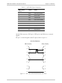
Table 2-1. Null Cable Pinout Connections
DB-9 Female
Pin No.
Signal
Name
1
DCD
Data Carrier Detect
2
RXD
Receive data
3
TXD
Transmit data
4
DTR
Data Terminal Ready
5
GND
Ground
6
DSR
Data Set Ready
7
RTS
Request To Send
8
CTS
Clear To Send
9
RI
Ring Indicator
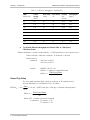
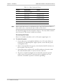
On both DB9 connectors, DCD (pin 1), DTR (pin 4) and DSR (6) are connected
together.
RTS (pin 7) is shorted together with CTS (pin 8). Refer to Figure 2-1.
CBL-DB-9/DB9/NULL
DB-9 (Female)
DB-9 (Female)
1
1
2
2
3
3
4
4
5
5
6
6
7
7
8
8
9
9
Figure 2-1. Null Cable (CBL-DB-9/DB-9/NULL) Pin Shorts
Equipment Needed
2-3
IPmux-16 Installation and Operation Manual
Chapter 2 Installation
2.5 Installation and Setup
Setting Jumpers
IPmux-16 internal jumpers and switches do not need to be configured by the user
and therefore removing the product cover is not required.
Connecting Interfaces and Cables
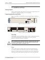
Figure 2-2 and Figure 2-3 illustrate the rear and front panel options available for
IPmux-16.
Figure 2-2. IPmux-16 Front Panel
PS2
POWER
O
O
I
POWER
I
PS1
~100-240VAC
3A T 125V
~100-240VAC
3A T 125V
ALARMS
EXT. CLK
Figure 2-3. IPmux-16 Rear Panel
Grounding
Interrupting the protective grounding conductor (inside or outside the instrument)
or disconnecting the protective earth terminal can make this instrument
dangerous. Intentional interruption is prohibited.
Before switching ON this instrument and before connecting any other cable,
the protective earth terminals of this instrument must be connected to the
protective ground conductor of the power cord.
Warning
Fuses
Make sure that only fuses with the required rated current and specified type,
2 A T 250V as marked on the IPmux-16 rear panel, are used for replacement.
Whenever it is likely that the protection offered by fuses has been impaired, the
instrument must be made inoperative and be secured to prevent any operation.
2-4 Installation and Setup
IPmux-16 Installation and Operation Manual
Chapter 2 Installation
Location of Connectors
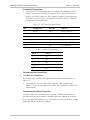
Connect the E1/T1 and Ethernet ports according to the appropriate pinout.
Interface connections are made from the IPmux-16 front panel from each
module, as shown in Figure 2-3. The connectors required for each interface
are listed in Section 2.4. E1/T1 port pinouts are listed in Table 2-2, Ethernet
port pinouts are listed Table 2-3.
•
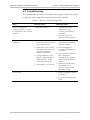
Table 2-2. E1/T1 Port Connectors Pinout
Pin
Designation
Direction
Function
1
RD (R)
Input
Receive data (ring)
2
RD (T)
Input
Receive data (tip)
3,6
–
–
FGND
4
TD (R)
Output
Transmit data (ring)
5
TD (T)
Output
Transmit data (tip)
7,8
–
N/A
Not connected
Table 2-3. Ethernet Port Pinout
Pin #
Pinout
1
Tx+
2
Tx–
3
Rx+
4, 5, 7, 8
–
6
Rx–
Connecting the Control Port
➤
To connect the Control Port:
The Control port is located on the right side of the IPmux-16 front panel (see
Figure 2-3).
•
Connect the RS-232/V.24, DB-9 DTE connector cable, supplied with
IPmux-16, to the IPmux and then to the DTE. The control port is DTE for an
ASCII terminal.
Connecting the Alarm Connector
An Alarms connector is located on the rear panel. A DB-9 female connector
provides alarm relay dry-contacts to external supervisory equipment (for future
use). This feature allows IPmux-16 to send alarms on its dry contact port. A single
output pin indicates an IPmux-16 alarm.
Installation and Setup
2-5
IPmux-16 Installation and Operation Manual
Chapter 2 Installation
Table 2-4. Alarm Connector Pinout
Note
Pin No.
Signal Name
Status
1, 2, 6, 7
Discrete line input
3
Minor alarm
Normally closed
4
Major alarm
Normally closed
5
Major alarm
Common contact
8
GND
9
Minor alarm
Normally closed
When a major alarm occurs, a relay between pins 4 and 5 will be closed. When a
minor alarm occurs, a relay between pins 3 and 9 will be closed.
The alarms that trigger the relay are listed in Chapter 3. The relay will be activated
only if the specific Alarm trap is enabled (not masked).
Connecting the Power
IPmux-16 is available with either an AC or a DC power supply (Figure 2-2).
➤
To connect the power:
1. Connect the power cord, supplied with IPmux-16, to PS1 on the IPmux-16
front panel. If a redundant power supply is present, connect the ther power
cord supplied to PS2.
2. Before connecting IPmux-16 to power, check that the ON/OFF switch(es) on
the rear panel is (are) set to OFF.
3. Connect the power cord first to PS1 (and PS2) and then to the mains outlet.
The outlet should be within 1.5 meters (five feet) of the unit.
4. The power cord must be plugged into an outlet with a protective ground
(earth) contact. The protective action must not be negated by use of an
extension cord without a protective conductor (grounding).
2-6 Installation and Setup
Chapter 3
Operation
3.1 Introduction
This chapter gives a detailed description of the front panel controls and indicators
and their functions, explains power-on and power-off procedures, and provides
instructions for using a terminal connected to the IPmux-16 Control Port.
3.2 Front Panel Controls, Connectors, and Indicators
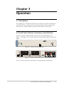
Interface modules installed in IPmux-16 have their own LED indicators (see
Figure 3-1 and Figure 3-2). The unit's LEDs are located on the right side of the front
panel.
Figure 3-1. IPmux-16 Front Panel LEDs
O
O
~100-240VAC
EXT. CLK
PS2
POWER
I
POWER
I
PS1
3A T 125V
~100-240VAC
3A T 125V
ALARMS
Figure 3-2. IPmux-16 Rear Panel Switch
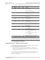
Table 3-1 lists the functions of the IPmux-16 system indicators and switches.
Front Panel Controls, Connectors, and Indicators
3-1
IPmux-16 Installation and Operation Manual
Chapter 3 Operation
Table 3-1. IPmux-16 System Indicators and Switches
No
Module
Name
Type
Function
1
System
RDY
LED
On: Device OK
OFF: Self-test in progress
Blinking: Malfunction detected
2
System
PS1/PS2
LED
On: Unit powered
Off: Unit not powered
3
System
ALM
LED
Red: Alarm
Off: No alarm
4
Ethernet
LINK
LED
Off: Link not active
On: Line OK
5
Ethernet
ACT
LED
Off: No activity
On: Frame being transferred on line
6
Ethernet
100M
LED
Off: 10 MHz
On: 100 MHz
7
Ethernet
FDX
LED
Off: Half duplex
On: Full duplex
8
E1
SYNC
LED
On: Port synchronized (no alarm)
Off: Unframed - Signal loss or AIS
detected
Framed - Signal loss, loss of frame or
AIS detected
Blinking: RDI detected (remote alarm)
9
Rear panel
PS1/PS2
Switch
Turns IPmux-16 power on and off
3.3 Operating Instructions
Turning IPmux-16 On – Without Control Terminal
IPmux-16 power switches are located on the back panel, as shown in Figure 3-2.
➤
To power up IPmux-16 without a terminal:
•
Switch the PS1 power supply switch, located on the rear panel, to ON.
IPmux-16 can be optionally equipped with a second power supply (PS2). If
present, switch PS2 to ON.
After power-up, check the unit LED indicators, located on the right side of the
front panel, and the module indicators for proper operation (see Figure 3-1,
Figure 3-2, and Table 3-1).
3-2 Operating Instructions
IPmux-16 Installation and Operation Manual
Chapter 3 Operation
Turning IPmux-16 On – With Control Terminal
➤
Note
To power up IPmux-16 with a control terminal:
If you want to download software, refer to Appendix A, which describes the boot
procedure for software download.
1. Verify that all IPmux-16 cables and connectors are properly connected.
2. Connect IPmux-16 to a PC equipped with an ASCII terminal-emulation
application (for example, Windows 95 Hyper Terminal or Procomm), with the
null cable supplied with the unit (CBL-DB9/DB-9/NULL).
3. Turn on the control-terminal PC.
Set the default port parameters to 19,200 baud, 8 bits/character, 1 stop bit, No
Parity.
Set the terminal emulator to ANSI VT100 emulation (for optimal view of
system menus).
4. Switch ON the PS1 power supply switch, located on the front panel. IPmux-16
can be optionally equipped with a second power supply (PS2). If present,
switch PS2 ON.
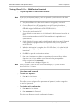
5. When the initialization is complete, the RDY LED (Figure 3-1) on the left side
of the front panel lights. If problems are encountered, refer to Chapter 4 for
instructions.
6. Press ESC to open the configuration software.
7. Enter your User Name according to your assigned system privileges (either
Supervisor (su) or User and then your Password when prompted (the
factory-set password is xxxxxxxxxx).
The Main Menu is displayed (Figure 3-4).
Note
If the password is invalid in three consecutive attempts, the system becomes
inaccessible for 15 minutes.
User Name and Password
➤
To enter as a superuser:
1. Enter su for User Name.
2. Enter xxxxxxxxxx for Password.
This allows you to configure all the parameters of Ipmux-16, and to change the
su and user passwords.
➤
To view the unit’s comfiguration:
1. Enter user for User Name.
2. Enter xxxxxxxxxx for Password.
This does not allow you to make configuration changes.
Operating Instructions
3-3
IPmux-16 Installation and Operation Manual
Chapter 3 Operation
➤
To set all passwords to the default value (xxxxxxxxxx):
1. Enter su for User Name.
2. Delete the unit’s configuration through the Configuration screens.
Note
➤
Deleting the unit’s configuration using <Cntl+A> and choosing 4 in the Boot
Menu does not set the passwords to the default value.
If a user forgets his password:
•
Consult Technical Support at RAD for further assistance (send email to
[email protected]).
Turning IPmux-16 Off
➤
To power off the unit:
1. If you are using a terminal connection, press escape until you return to the
main menu and press 4. Exit.
2. Switch PS1 (and PS2 if connected) to OFF.
3.4 Getting Started
After installation, there are no special operating procedures for IPmux-16. Once it
is powered up, the unit operates automatically. Proper operation is indicated by
the front-panel LED indicators (Figure 3-1 and Figure 3-2). The unit operational
status can be monitored constantly.
If required, the IPmux-16 can be reconfigured. Both the IPmux-16 configuration
and monitoring operations are performed locally from an ASCII terminal, Telnet or
NMS connected to the Control Port. Detailed configuration procedures are given
later in this chapter. The following functions are supported:
•
View system information
•
Modify configuration and mode of operation, including setting system default
values
•
View statistics and status
•
Perform diagnostics.
IPmux-16 configuration and system monitoring, including troubleshooting
procedures, can also be performed from a remote site using a Telnet application or
RADview (RAD’s HP OpenView based SNMP).
Note
3-4 Getting Started
Telnet and the local terminal cannot work simultaneously.
IPmux-16 Installation and Operation Manual
Chapter 3 Operation
3.5 Menu Operations
Navigating
Navigate the IPmux-16 terminal menus to set and view configuration parameters.
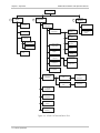
Figure 3-3 maps the IPmux-16 terminal menus. Use this tree as a reference aid
while performing configuration and control functions.
Menu Operations
3-5
IPmux-16 Installation and Operation Manual
Chapter 3 Operation
Main Menu
1
System
2
1. General
Information
Configuration
3
Performance
Monitoring
1. General
1. Statistics
Configuration
1. Management
1. Authentication/
Configuration
2. Reset
Community
2. IP Channel
Status
2. Host
Configuration
3. Event Log
3. Manager
1. Read Logfile
Configuration
2. ASCII Terminal
Configuration
2. Clear Logfile
4. Default
Gateway
3. Time/Date
Update
4. Ping
5. Alarms Traps
MASK
4. Software
1. Configuration
Using XMODEM
Download
5. Set Default
2. Configuration
Using TFTP
Parameters
6. File System
2. Physical Layer
1. Ethernet
Configuration
Card
3. E1/T1
Card
3. Time Slot
Configuration
4. Channel IP
Configuration
5. VLAN & IP
Support
6. Configuration
Summary
Figure 3-3. IPmux-16 Terminal Menu Tree
3-6 Menu Operations
1. LAN Physical
Layer
Configuration
1. Physical Layer
Configuration
IPmux-16 Installation and Operation Manual
Chapter 3 Operation
Main Menu
Figure 3-4 shows the IPmux-16 Main Menu. Access all system configuration and
control functions via this menu.
At any point and from any screen, you can press ESC repeatedly, backing up until
you reach the main menu.
Only from this menu can you exit the program. In order to prevent unauthorized
access, it is recommended that when you finish a session, you return to the Main
Menu and type 4 to exit the program. A password is then required for reentry.
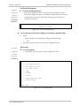
MAIN MENU
1.System
2.Configuration
3.Performance Monitoring
4.Exit
Select item from the menu:
>
>
>
_
Figure 3-4. Main Menu
The Main Menu options are:
1. System
View and modify system parameters
2. Configuration
Define device configuration
3. Performance Monitoring
Monitor device performance
4. Exit
Exit the control software
3.6 Configuring System Parameters
Viewing System Information
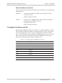
➤
To access the System menu:
•
Main Menu
↓
1. System
Type 1 (System) in the Main Menu.
From the System menu you can view and configure the following options:
1. General Information
View IPmux-16 general information
2. Reset
Reset IPmux-16
3. Event Log
View a list of IPmux-16 events
4. Ping
Ping other network devices
Configuring System Parameters
3-7
IPmux-16 Installation and Operation Manual
Chapter 3 Operation
SYSTEM
1.General Information
3.Reset
>
4.Event Log
5.Ping
ESC.
Exit
Select item from the menu.
Figure 3-5. System Menu
Main Menu
↓
1. System
↓
1. General
Information
General Information
➤
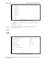
To display IPmux-16 general information:
• Type 3 (Event Log) in the System Menu.
• Type 1 (General Information) in the System Menu. This displays
information including software and hardware versions and module
descriptions. A typical General Information window for an IPmux-16 is
shown in the following figure.
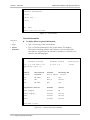
GENERAL INFORMATION
Software Versions
Hardware Version
Boot: 1.0 1-28-2001 17:16
0.2-C/1.1-A
Inventory No.
133735
Application: beta 1.0
Modules
Description
Version
Inventory No.
Network
ETHERNET
HW:4.0 SW:M.2
User
NO CARD
N/A
N/A
User
4E1
HW:2.0
184645
User
NO CARD
N/A
N/A
Peripherals devices
Present
Status
Power supply1
Present
OK
Power supply2
Present
Failed
Fan1
Present
Failed
Fan2
Present
Failed
226833
Press ESC to exit.
Figure 3-6. General Information Window
3-8 Configuring System Parameters
IPmux-16 Installation and Operation Manual
Main Menu
↓
1. System Menu
↓
3. Event Log
Chapter 3 Operation
Event Log
➤
To view the IPmux-16 event log:
• Type 3 (Event Log) in the System Menu.
EVENT LOG
1. Read logfile
2. Clear logfile
ESC. To Exit
Select item from the menu:
Figure 3-7. The Event Log Window
− Type 1 to read the logfile.
− Type 2 to clear the logfile.
For a complete list of events, refer to Table 3-2.
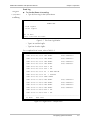
LOGFILE EVENTS
2001-01-29 09:31:51 LOS START
Slot3 Channel4
2001-01-29 09:31:51 LOS START
Slot3 Channel3
2001-01-29 09:31:51 LOS START
Slot3 Channel2
2001-01-29 09:31:51 LOS START
Slot3 Channel1
2001-01-29 09:31:51 Fan 2
OK
2001-01-29 09:31:51 Fan 1
OK
2001-01-29 09:31:51 PS
2
NOT ACTIVE
2001-01-29 09:31:51 PS
1
ACTIVE
2001-01-29 09:31:51 COLD START
2001-01-28 17:48:49 LOS START
Slot3 Channel4
2001-01-28 17:48:49 LOS START
Slot3 Channel3
2001-01-28 17:48:49 LOS START
Slot3 Channel2
2001-01-28 17:48:49 LOS START
Slot3 Channel1
2001-01-28 17:48:49 Fan 2
OK
2001-01-28 17:48:49 Fan 1
OK
--------------------------------------------------------------N. Next
ESC. Exit
Figure 3-8. Logfile Events – Sample Menu
Configuring System Parameters
3-9
IPmux-16 Installation and Operation Manual
Chapter 3 Operation
Ping
Main Menu
↓
1. System
↓
4. Ping
This option enables the user to ping other network devices for diagnostic
purposes.
➤ To ping:
• Type 4 (Ping) in the System Menu.
Enter the destination IP address.
• Press the <Spacebar> to set the number of ping repetitions.
• Press <Enter> to apply the settings.
PING
Enter Destination IP And Press Enter.
Destination IP: 111.123.112.215
Use Space Bar To Choose Ping Repetitions.
Ping Repetitions: 1
Ping Result: Host 192.115.70.13 Request Timed Out.
Press Esc. to Exit, Or Any Other Key To Refresh Screen
Figure 3-9. Ping Dialog Box
3.7 Configuring IPmux-16
➤
To access the Configuration menu:
•
Type 2 (Configuration) in the Main Menu.
Main Menu
↓
2. Configuration
From the Configuration menu you can view and configure the following options:
1. General Configuration
Configure Host IP, Default Gateway,
Management Configuration, ASCII
Terminal Configuration, Time/Date
update, Default parameters, and
download software updates
2. Physical Layer Configuration
Configure E1/T1 and Eth physical layer
configuration
3. Time Slots Configuration
Configure bundles and assign timeslots
4. Bundle Connection Configuration
Configure connection parameters
3-10 Configuring IPmux-16
IPmux-16 Installation and Operation Manual
Chapter 3 Operation
5. VLAN & IP Support
Configure IP ToS and VLAN tagging
6. Configuration Summary
View summary information of all existing
bundle connections.
CONFIGURATION
1. General Configuration
2. Physical Layer Configuration
3. Time Slots Configuration
4. Bundle Connection Configuration
5. VLAN & IP Support
6. Configuration Summary
ESC. Exit
Select item from the menu:
_
Figure 3-10. Configuration Menu
General Configuration
Main Menu
↓
2. Configuration
↓
1. General
Configuration
➤
To display the General Configuration Menu.
• Type 1 (General Configuration) in the Configuration Menu, above.
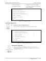
GENERAL CONFIGURATION
1. Management Configuration
>
2. ASCII Terminal Configuration
>
3. Time/Date Update
>
4. Download/Upload
>
5. Set Default Parameters
6. File System
>
ESC. Exit
Select item from the menu.
Figure 3-11. General Configuration Menu
Management Configuration
Main menu
↓
2. Configuration
↓
1. General Configuration
↓
1. Management
Configuration
Enter 1 from the General Configuration menu to access IPmux-16
management parameters; the Management Configuration menu will then
be displayed (Figure 3-12).
Configuring IPmux-16
3-11
IPmux-16 Installation and Operation Manual
Chapter 3 Operation
MANAGEMENT CONFIGURATION
1. Authentication/Community
>
2. Host Configuration
>
3. Manager List
>
4. Default Gateway
>
5. Alarms Traps Mask
>
Select item from the menu:
_
Figure 3-12. The Management Configuration Menu
The Management Configuration menu options are:
•
Authentication/Community
•
Host configuration
•
Manager list
•
Default Gateway
•
Alarm traps MASK.
Authentication/Community
Main menu
↓
2. Configuration
↓
1. General Configuration
↓
3. Management
Configuration
↓
1. Authentication/
Community
Enter 1 from the Management Configuration menu; the Community
window will then be displayed (Figure 3-13).
The Authentication/Community parameters are used when the IPmux-16
inband management capability is used. The parameters define the
community names used by SNMP to write, read or accept traps from
IPmux-16. The default value for all three operations is public.
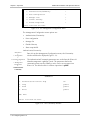
COMMUNITY
1.
Authentication Failure Trap
On
2.
Trap
public
3.
Read
public
4.
Write
public
ESC. Exit
Select item from the menu:
_
Figure 3-13. The Community Window
3-12 Configuring IPmux-16
IPmux-16 Installation and Operation Manual
➤
Chapter 3 Operation
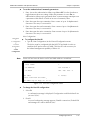
To set the Authentication/Community parameters:
1. Enter 1 to set the authentication-failure trap: On or Off. Use the Spacebar to
toggle between these two settings. When this parameter is set to On, an
authentication-failure trap is generated when a system manager attempts to set
a parameter within IPmux-16 with an incorrect community value.
2. Enter 2 to name the trap community: Enter a name of up to 10 alphanumeric
characters. The entry is case-sensitive.
3. Enter 3 to name the read community: Enter a name of up to 10 alphanumeric
characters. The entry is case-sensitive.
4. Enter 4 to name the write community: Enter a name of up to 10 alphanumeric
characters. The entry is case-sensitive.
Main Menu
↓
2. Configuration
↓
1. General
Configuration
↓
2. Host
Configuration
Note
Host Configuration
➤
To configure the Host IP:
• Type 2 ( Host Configuration) in the General Configuration menu.
The device must be configured with the HOST IP and Mask in order to
combine the IP packet (source IP Add). This Host IP is also necessary for
the inband management capability of IPmux-16.
Frames will not leave the device until IP and Mask addresses are defined.
HOST CONFIGURATION
1. Host Index
1
2. IP Address
192.168.100.1
3. IP Mask
255. 255. 255. 0
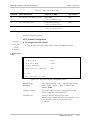
ESC. Exit
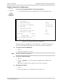
D. Delete
Select item from the menu:_
Use <ESC> key or keys <1> to <3>
Figure 3-14. User Port Configuration Menu
➤
To change the Host ID configuration:
1. Select D.
A confirmation message is displayed “Configuration would be deleted! Are
you sure? (Y/N)”.
2. Press Y.
A second confirmation message appears “Bundle connections, Default GW
and Managers IP's will be deleted (Y/N)”.
Configuring IPmux-16
3-13
IPmux-16 Installation and Operation Manual
Chapter 3 Operation
3. Press Y.
The Host IP is deleted.
4. Configure the new Host IP.
Note
Deletion of Host ID automatically deletes the following parameters:
Host IP, Default Gateway, all Managers connected to the host, and all Bundle
Connections.
Manager List
Main menu
↓
2. Configuration
↓
1. General Configuration
↓
3. Management
Configuration
↓
3. Manager List
Enter 3 from the Management Configuration menu; the Manager List
window will then be displayed (Figure 3-15).
MANAGER LIST
1. Manager IP Address
192.114.35.1
2. Host Index
1
3. Alarm Trap
Off
4. System Trap
On
ESC.
Exit S.
Save
After Save: ESC.
Exit D.
Select item from the menu:
P. Ping
N.
N.
Next
Next
_
Figure 3-15. The Manager List Window
The Manager List window parameters are used when IPmux-16 inband
management capability is used. The parameters define the parameters for up to
eight managers. These parameters are:
•
Manager IP address
•
Host index
•
Alarm Trap
•
System Trap.
In addition, the Manager List window parameters configure the traps to be
received by a manager. The default value for all traps is Off.
3-14 Configuring IPmux-16
IPmux-16 Installation and Operation Manual
➤
Chapter 3 Operation
To set the manager list parameters:
1. Enter 1 to set the manager IP address: range of 0.0.0.0. to 255.255.255.255.
2. Enter 3 to set the alarm trap: On or Off. Use the Spacebar to toggle between
these two settings. When set to On, the alarm trap informs the manager of the
occurrence of any alarm enabled in the Alarms Trap Mask screen. It informs
the manager of both entry and exit from an alarm state. When OFF, no alarm
trap will be sent regardless of the Mask defined in the Alarm Trap Mask screen.
3. Enter 4 to set the system trap: On or Off. Use the Spacebar to toggle between
these two settings. When set to On, the system trap informs the manager
whenever there is a change in the system power-supply status, heat alarm.
4. To ping the manager, press P.
5. To access additional manager-list parameters, press N to go to the next
manager-list window.
Main menu
↓
2. Configuration
↓
1. General
Configuration
↓
3. Management
Configuration
↓
4. Default
Gateway
Default Gateway
Default gateway defines the gateway to which management frames will be sent
(when the manager is not in the host subnet). When a next hop is not defined in
the connection parameters, the default gateway is used.
➤ To configure the default gateway
1. Type 4 (Default Gateway) in the Management Configuration menu.
DEFAULT GATEWAY
1. Gateway IP
0.0.0.0
ESC. Exit
Select item from the menu.
Figure 3-16. Default Gateway Menu
2. Type 1 and then type in the IP address of the default gateway.
Configuring IPmux-16
3-15
IPmux-16 Installation and Operation Manual
Chapter 3 Operation
Alarms Trap Mask
Main menu
↓
2. Configuration
↓
1. General Configuration
↓
3. Management
Configuration
↓
5. Alarms Trap Mask
Enter 5 from the Management Configuration menu; the Alarms Trap Mask
window will then be displayed (Figure 3-15).
Alarms Trap Mask
1.
Alarm ID (refer to Manual)
1
2.
Trap Status
Active
ESC. Exit
S. save
ACTIVE ALARM TRAPS:
1, 2, 6, 8
Figure 3-17. The Alarms Trap Mask Window
Each of the IPmux-16 alarms can activate a trap toward the NMS. It is possible to
enable/disable the trap operation for each one of the alarms, using the Alarm Trap
Mask screen.
➤
To define the Alarms Traps Mask:
•
Type 3 (Alarms Trap Mask) in the Management Configuration Window.
The Alarms Traps Mask window is displayed.
➤
To activate/deactivate a trap generation for an alarm
•
➤
Type 1 and enter the alarm ID (see Table 3-1). The relevant range is 1-40.
To change the trap status:
•
Type 2 (Trap status) and press <Spacebar> to toggle between ACTIVE
(generate a trap) and MASKED (no alarms sent). The default for all traps is
MASKED.
Table 3-2. IPmux-16 Alarms
Alarm ID
Alarm Description
Trap Sent to NMS
Dry Contact
1
Loss of Signal (LOS Physical Layer)
Alarm LOS
1.3.6.1.4.1.164.6.1.3.0.7
Major
2
Loss of Frame (LOF Physical Layer)
Alarm LOF
1.3.6.1.4.1.164.6.1.3.0.8
Major
6
Alarm Indication Signal Received (AIS
Line Physical Layer)
Alarm AIS
1.3.6.1.4.1.164.6.1.3.0.10
Major
8
Remote Defect Indication Received
(RDI Line Physical Layer)
Alarm RDI
1.3.6.1.4.1.164.6.1.3.0.11
Major
3-16 Configuring IPmux-16
IPmux-16 Installation and Operation Manual
Chapter 3 Operation
Table 3-2. IPmux-16 Alarms (Cont.)
Alarm ID
Alarm Description
Trap Sent to NMS
Dry Contact
21
Far End Block Error (FEBE Line Layer)
Alarm FEBE
1.3.6.1.4.1.164.6.1.3.0.12
Major
26
Local Connectivity Fail
Local Conn Status Trap
1.3.6.1.4.1.164.6.1.3.0.13
Minor
27
Remote Connectivity Fail
Remote Conn Status Trap
1.3.6.1.4.1.164.6.1.3.0.14
Minor
All other Alarms are unused.
Main Menu
↓
2. Configuration
↓
1. General
Configuration
↓
2. ASCII Terminal
Config.
ASCII Terminal Configuration
➤ To configure the ASCII terminal
• Type 2 (ASCII Terminal Config.) in the General Configuration menu.
ASCII Terminal Configuration
1. Display Mode
Color
2. Baud Rate [bps]
19200
3. Change Password
4. Hard flow ctrl (RTS/CTS)
Off
ESC. Exit
Select item from the menu:_
Figure 3-18. The ASCII Terminal Configuration Menu
Display Mode:
Baud Rate
Color / MonoChrome 3 color / MonoChrome 2 color
9600 / 19200 / 38400 / 57600 – in units of bps
Default: 19200
Change Password
Choose this option to enter a menu that allows the
user to change the current password
Hard flow ctrl
Set the 15 minute timeout to On or Off
When On the terminal will exit to the password screen
if no characters were sent by the terminal for
15 minutes.
Configuring IPmux-16
3-17
IPmux-16 Installation and Operation Manual
Chapter 3 Operation
Main Menu
↓
2. Configuration
↓
1. General
Configuration
↓
3. Time/Date
Update
Time/Date Update
Type 3 (Time/Date Update) in the General Configuration menu to update the
time and date.
TIME/DATE UPDATE
1. Set Time (hh:mm:ss)
16:09:12
2. Set Date (yyyy-mm-dd)
2001-07-02
ESC. Exit
Select item from the menu:_
Figure 3-19. Time/Date Update Menu
Main Menu
↓
2. Configuration
↓
1. General
Configuration
↓
4. Software
Download/Upload
➤
Set Time
Time setting in the device.
Range: (00:00:00 – 23:59:59)
Set Date
Date setting in the device.
Range: (1970/01/01 – 2099/01/01)
Software Download/Upload
You can download/upload upgrades to IPmux-16 via the terminal. The software
download/upload option can be used to download/upload three types of code:
Boot code, Application code and LAN code; the software download/upload
operation does not change the IPmux-16 configuration code.
To perform Software Download/Upload:
•
Type 4 (Software Download) in the General Configuration menu.
The Software Download Upload menu is displayed.
SOFTWARE DOWNLOAD/UPLOAD
1. Download/Upload using XMODEM
>
2. Download/Upload using TFTP
>
ESC. Exit
Select item from the menu.
Figure 3-20. The Software Download Upload Window
3-18 Configuring IPmux-16
IPmux-16 Installation and Operation Manual
➤
Chapter 3 Operation
To download/upload the code/configuration:
1. Type 1 in the Software Download/Upload menu to download/upload using
XMODEM.
2. Type 2 to download/upload via TFTP.
X-Modem
Main Menu
↓
2. Configuration
↓
1. General Configuration
↓
4. Software
Download/Upload
↓
1. Download/Upload
Xmodem
Enter 1 from the Software Download/Upload window to download or
upload a file by X-modem. The Download/Upload Using X-Modem
window is displayed.
Download/Upload Using XMODEM
File
application code
ESC. Exit
D. Download U. Upload
Figure 3-21. Download/Upload Using X-Modem Window
➤
To download or upload a file by X-Modem, do the following:
1.
Enter 1 from the Download/Upload Using X-Modem window and enter
in the file name to be downloaded or uploaded. The file options are
listed. Remember that only configuration files can be uploaded. If you
choose any other file, the U. Upload option is not displayed.
2.
Enter D to download a software or configuration file or U to upload a
configuration file (the upload option is for configuration only), as
desired. You will be asked for confirmation. Upon confirmation, the
download or upload procedure begins.
Configuring IPmux-16
3-19
IPmux-16 Installation and Operation Manual
Chapter 3 Operation
TFTP
Main Menu
↓
2. Configuration
↓
1. General Configuration
↓
4. Software
Download/Upload
↓
2. Download/Upload
TFTP
Enter 2 from the Software Download window to download or upload a file
by TFTP; the TFTP window is displayed.
DOWNLOAD\UPLOAD Using TFTP
1. File name
“3V00.cmp”
2. Command
3. Server IP
IP address
4. Retry timeout
15
5. Total timeout
60
6. User File Name
XXXXXXXXX.YYY
7. View transfer status
¾
ESC. Exit
S. Save & Start action
Figure 3-22. Download/Upload Using TFTP Window
➤
To download or upload a file by TFTP, do the following:
1.
Enter 1 from the Download/Upload using TFTP window then type the
file name to be downloaded or uploaded.
2.
Enter 2 and type the command to be executed on the file.
− SW download
− config download
− config upload
− LAN code download
Note
Boot code download is not possible using TFTP.
3-20 Configuring IPmux-16
3.
Enter 3 and type the IP address of the server from which the file is
loaded.
4.
Enter 4 and type in the desired retry timeout period (in seconds).
5.
Enter 5 and type in the desired total timeout period (in seconds), which
is the maximum time allowed for attempted transmission.
IPmux-16 Installation and Operation Manual
Chapter 3 Operation
6.
Enter S to save the parameters and start the transmission process. If all
parameters are correct, you will be asked for confirmation. Transmission
begins only after confirmation.
7.
Enter 6 to enter a User file name.
8.
Enter 7 to view the transfer status in real-time; the View Transfer Status
window is displayed.
VIEW TRANSFER STATUS
Status
Transferring Data
Error
No Error
ESC. Exit
Figure 3-23. View Transfer Status Window
The View Transfer Status window is updated every second. The screen is read-only
with these possible options:
•
Status indication possibilities are:
− No Operation
− Connecting
− Transferring Data
− Ended on Time Out
− Ended OK
− Error.
•
Error message possibilities are:
− Unavailable (no host IP)
− No Error
− File Not Found
− Illegal TFTP Operation
− Unknown Transfer ID
− Illegal PDU Size
− Illegal File Mode
− No Empty Connection
− No Empty UDP Port
− Server Overflow.
After confirmation, the TFTP session will begin.
Configuring IPmux-16
3-21
IPmux-16 Installation and Operation Manual
Chapter 3 Operation
Main Menu
↓
2. Configuration
↓
1. General
Configuration
↓
5. Set Default
Parameters
Set Default Parameters
➤
To set the default parameters:
• Type 5 (Set Default Parameters) in the General Configuration menu.
This will reconfigure the device according to default parameters. Before
overwriting the system, the following warning appears asking you to
confirm your selection.
Configuration will be overwritten and system will RESET.
Continue ? (Y/N)
Figure 3-24. Reset Default Warning
➤
To overwrite the system and reconfigure it according to default settings:
•
Type Y.
IPmux-16 will be reconfigured according to default settings.
OR
•
Main Menu
↓
1. Configuration
↓
2. General
Configuration
↓
6. File System
Type N to exit and return to the General Configuration menu.
File System
➤ To set File options:
• Type 6 (File System) in the General Configuration menu.
File System
1. Dir (System Files)
2. Dir (History Files)
3. Dir (User Files)
4. Copy
5. Rename
6. Delete
7. Print Code-File Info
8. Format Flash
ESC. Exit
Figure 3-25. File System Menu
3-22 Configuring IPmux-16
IPmux-16 Installation and Operation Manual
Chapter 3 Operation
➤ Select the items from the File System to obtain the display of the following
information:
1. Dir (System Files) – Shows the system files. The system files have specific
designation in accordance to their contents and functions as follows:
M
B
C
1
CDB
2
CFG
T
LOG
COD
•
M, B and T are for Main, Backup and Temporary respectively
•
C for CPU
•
1, 2 for C1, C2 for CPU1 (located in the main board) and CPU2 (in the LAN
module)
•
CDB, CFG, LOG, COD for:
− CDB - Configuration Data Base (MIB information)
− CFG - Configuration files
− LOG - Log (alarms and events) files
− COD - Code files
2. Dir (History) – Not applicable
3. Dir (User files) – Displays user files. User files are private user files (not System
or History files)
4. Copy – To copy the file content (can be used also to backup a file)
5. Rename – Rename a file name
6. Delete – Delete a file
7. Print Code – Provides code file information such as target, version and date
8. Format Flash – Format file system. This selection erases all files and initiates the
file system. A warning appears asking for the user’s permission before
beginning the process.
Configuring IPmux-16
3-23
IPmux-16 Installation and Operation Manual
Chapter 3 Operation
Main Menu
↓
2. Configuration
↓
2. Physical Layer
Configuration
Physical Layer Configuration
➤ To configure the IPmux-16 physical layer:
• Type 2 (Physical Layer Configuration) in the Configuration menu.
PHYSICAL LAYER CONFIGURATION
1. Slot #1 – ETHERNET
>
2. Slot #2 - NO CARD
3. Slot #3 – 4E1/T1
>
4. Slot #4 – 8E1/T1
>
ESC. Exit
Figure 3-26. Physical Layer Configuration Menu
Main Menu
↓
2. Configuration
↓
2. Physical Layer
Configuration
↓
1. LAN Physical
Layer
Configuration
LAN Configuration
➤ To view and configure LAN port type:
• Type 1 to access your Ethernet card (LAN Physical Layer Configuration) in
the Physical Layer Configuration menu.
LAN PHYSICAL LAYER CONFIGURATION
1. Auto Negotiation
Enable
2. Max Capability advertised
100baseT Full Duplex
3. Default type
100baseT Full Duplex
ESC. Exit
Select item from the menu.
Figure 3-27. LAN Physical Layer Configuration Menu
➤
To enable or disable the auto-negotiation mode:
•
Type 1.
Use the spacebar on your keyboard to toggle between Enable and Disable.
(Autonegotiation mode is according to RFC 2239.)
3-24 Configuring IPmux-16
IPmux-16 Installation and Operation Manual
Note
➤
If Auto Negotiation is set to Enable and there is some incompatibility in the
Auto Negotiation process, Ipmux-16 automatically changes to half-duplex mode. To
overcome this situation, set Auto Negotiation to Disable and set Default type to the
desired mode.
To define the maximum capabilities of the module for the auto-negotiation
process (can be lower then the actual capabilities):
•
➤
Chapter 3 Operation
Type 2.
Use the <Spacebar> on your keyboard to toggle between the parameters:
10BaseT Half Duplex, 10BaseT Full Duplex, 100BaseT Half Duplex,
100BaseT Full Duplex.
To set the default parameters:
1. Type 3.
2. Use the <Spacebar> on your keyboard to toggle between the module mode
(half/full duplex) and Rate (10mbps/100Mbps).
Note
Main Menu
↓
2. Configuration
↓
2. Physical Layer
Configuration
↓
3 or 4. E1/T1
Physical Layer
Configuration
This parameter is valid only when the auto-negotiation mode is disabled
(RFC 2239).
E1/T1 Configuration
➤ To configure the E1/T1 interfaces:
• Type 3 or 4 (according to slot containing E1/T1 module) (E1/T1
Configuration) in the Physical Layer Configuration menu.
Configuring IPmux-16
3-25
IPmux-16 Installation and Operation Manual
Chapter 3 Operation
E1/T1 PHYSICAL LAYER CONFIGURATION
1. Channel #1
>
2. Channel #2
>
3. Channel #3
>
4. Channel #4
>
5. Channel #5
>
6. Channel #6
>
7. Channel #7
>
8. Channel #8
>
ESC. Exit
Current Slot is
3
Figure 3-28. E1/T1 Physical Layer Configuration Menu
Once you choose a channel number, the E1 or T1 Physical Layer Configuration
menu appears.
Main Menu
↓
2. Configuration
↓
2. Physical Layer
Configuration
↓
3 or 4. E1/T1
Physical Layer
Configuration
E1 Physical Layer Configuration
Type 1 (Physical Layer Configuration) in the E1/T1 Configuration menu to
configure the E1 physical layer.
PHYSICAL LAYER CONFIGURATION
1. Transmit Clock Source
Adaptive
2. Loopback State
Disable
3. Rx. Sensitivity
-10dB
4. Line Type
CRC4 enable
5. Idle Code
7E
6. Signaling Mode
CAS enable
7. Cond. Data pattern
FF
8. Cond. CAS (ABCD)pattern
01
ESC. Exit
Current Slot/Channel is 3/1
Figure 3-29. E1 Physical Layer Configuration Menu
3-26 Configuring IPmux-16
IPmux-16 Installation and Operation Manual
Note
➤
When “unframed” mode is selected, the Idle Code, Signaling Mode, Cond Data
Pattern and Cond CAS Pattern fields are not present.
When CAS Disabled is selected, the Cond CAS Pattern field is not present.
To change the source of the transmit clock:
•
➤
Chapter 3 Operation
Type 1 and press the <Spacebar> on your keyboard to toggle between
Adaptive/Loopback/Internal/External.
Adaptive:
Adaptive clock regeneration
Loopback:
The E1 recovered receive clock is used as the transmit clock.
Internal:
A local clock source is used.
Default value: Adaptive
To change the Loopback State setting:
Refer to Chapter 4 for detailed instructions on loopback tests.
➤
To change the RX Sensitivity setting:
•
Type 3 and press the <Spacebar> on your keyboard to toggle between
–10 dB / –32 dB. This setting determines the maximum attenuation of the
receive signal that can be compensated for by the interface receive path.
Default value: E1: -10 dB
➤
To change the Line Type setting:
•
Type 4 and press the <Spacebar> on your keyboard to toggle between CRC4
Enable / CRC4 Disable / UNFRAMED. This setting determines the framing
mode and operation mode for each configuration.
− Unframed: Framer will be configured to pass through mode and the
operation mode will be set to Unframed (see Chapter 1, section 1.3).
− CRC4 Enable: Framer will be configured to CRC4 MF mode. Operation
mode will be set by Signaling Mode field #6 to either Fractional or
Fractional with CAS (see Chapter 1, section 1.3).
− CRC4 Disable: CRC4 MF mode is disabled. Operation mode will be set by
Signaling Mode field #6 to either Fractional or Fractional with CAS (see
Chapter 1, section 1.3).
Default value: CRC4 enabled
Note
➤
Changing the Line Type setting will delete all connections.
To determine the idle code inserted into unused time slots by IPmux-16-E1 at
the transmit path towards E1 equipment:
•
Type 5 (Idle code) and enter a new value.
(This field will not appear if “unframed” is selected in the Line Type field.)
Range: 00-FF
Default value: 7E
Configuring IPmux-16
3-27
IPmux-16 Installation and Operation Manual
Chapter 3 Operation
➤
To determine the Signaling mode ( CAS enable / CAS disable ):
•
➤
To determine the byte code applied to time slots when fault conditions occur:
•
➤
Type 6 (Signaling mode).
If enabled, the E1 framer is set to CAS MF mode and the operation mode to
fractional with CAS mode. If disabled, CAS MF will not be set in the E1 framer
and the operation mode will be configured to fractional mode.
(This field will not appear if “unframed” is selected in the Line Type field.)
Default value: CAS Enable
Type 7 (Cond. data pattern) and enter a new value.
Conditioning pattern can be applied to time slots toward the IP path when loss
of signal, loss of frame or AIS detected at the E1 line. Conditioning pattern can
also be applied to time slots toward the E1 line when packet receive buffer
overrun or under-run occurs. In Unframed mode, conditioning state will result
in AIS transmission. This will be applied when a LOS is detected at E1 line, or
when packet receive buffer overrun or under run occurs. (This field will not
appear if “unframed” is selected in the Channel Type field.)
Range: 00-FF
Default Value: FF
To determine the 4 bit code applied to ABCD bits when fault conditions occur:
•
Type 8 (Cond CAS (ABCD) pattern).
The ABCD conditioning pattern can be applied toward the IP path when loss
of signal, loss of frame, or AIS is detected at the E1 line. Conditioning pattern
can also be applied toward the E1 line when packet receive buffer overrun or
underrun occur.
(This field will not appear if “unframed” is selected in the Channel Type field.)
Range: 1 - F
Default Value: 1
3-28 Configuring IPmux-16
IPmux-16 Installation and Operation Manual
Chapter 3 Operation
T1 Physical Layer Configuration
T1 PHYSICAL LAYER CONFIGURATION
1. Transmit Clock Source
Adaptive
2. Loopback State
Disable
3. Channel Type
T1-ESF
4. Channel Code
B8ZS
5. Channel Mode
DSU
6. Channel Length/Tx Gain
0-133
7. Restore Time
1 second
8. Idle Code
7E
9. Signaling Mode
CAS enable
A. Cond. Data pattern
7F
B. Cond. CAS (AB/ABCD) pattern
01
C. Cond. CAS first 2.5sec pattern(FF=NULL)
FF
ESC. Exit
Current port is the USER PORT
Select item from the menu.
Figure 3-30. T1 Physical Layer Configuration Menu
Note
➤
When “unframed” mode is selected, the Restore Time, Idle Code, Signaling Mode,
Cond Data Pattern, Cond CAS (AB/ABCD) Pattern and Cond. CAS first 2.5sec
pattern (FF=NULL) fields are not present.
When CAS Disabled is selected, the Cond CAS Pattern and Cond. CAS first 2.5sec
pattern (FF=NULL) fields are not present.
To change the source of the transmit clock:
•
Type 1 and press the spacebar on your keyboard to toggle between
Adaptive/Loopback/Internal/External
Adaptive:
Adaptive clock regeneration
Loopback:
T1 recovered receive clock used as the transmit clock
Internal:
Local clock source used
Default value: Adaptive
Configuring IPmux-16
3-29
IPmux-16 Installation and Operation Manual
Chapter 3 Operation
➤
To change the Loopback State setting:
•
Type 2 and press the spacebar on your keyboard to toggle between:
Internal / External / Disable.
− Internal: Data received from the IP network side will be looped back to the
network transmit line. An unframed all ‘1’ code (AIS) will be transmitted in
the T1 Tx path toward the PBX. Incoming data from the PBX will be
ignored.
− External: Data received from the PBX at the receive T1 line will be looped
back to the T1 Tx path (toward the same PBX), and will continue its way to
the IP network. Data coming from the IP network will be ignored.
− Disable: No loopback. Regular operation.
Default value: Disable
➤
To change the Channel Type setting:
•
Type 3 and press the spacebar on your keyboard to toggle between
T1-D4, T1-ESF, Unframed. This setting determines the framing mode and
operation mode for each configuration.
− T1-D4: Framer will be configured to T1-D4 mode. Operation mode will be
set by Signaling mode field #6 to either Fractional or Fractional with CAS
(see Chapter 1, section 1.3).
− T1-ESF: Framer will be configured to T1-ESF mode. Operation mode will
be set by signaling mode field #6 to either Fractional or Fractional with
CAS (see Chapter 1, section 1.3).
− Unframed: Framer will be configured to pass through mode and the
operation mode will be set to Unframed (see Chapter 1, section 1.3).
Default value: T1-ESF
Note
➤
Changing the Channel Type setting will delete all connections.
To change the Channel Code setting:
•
➤
Type 4 and press the spacebar on your keyboard to toggle between
B7ZS , B8ZS, AMI
Default value: B8ZS
To change the Channel Mode setting:
•
Type 5 and press the spacebar on your keyboard to toggle between
DSU and CSU
Default value: DSU
3-30 Configuring IPmux-16
IPmux-16 Installation and Operation Manual
➤
Chapter 3 Operation
To change the Channel Length / TX Gain setting:
When DSU is selected:
•
Type 6 and press the spacebar on your keyboard to toggle between
0–133, 134–266, 267–399, 400–533, 534–655
Default value: 0–133
When CSU is selected:
•
➤
Type 6 and press the spacebar on your keyboard to toggle between
0 dB, –7.5 dB, –15 dB, –22.5 dB.
Default value: 0 dB
To change the Restore Time setting:
This setting chooses the T1 red alarm recovery time.
•
➤
To determine the idle code inserted into unused time slots by IPmux-16-T1 at
the transmit path towards T1 equipment:
•
➤
Type 8 (Idle code) and enter a new value.
(This field will not appear if “unframed” is selected in the Line Type field.)
Range: 00–FF
Default value: 7E
To determine the Signaling mode (CAS enable / CAS disable):
•
➤
Type 7 and press the spacebar on your keyboard to toggle between
1 second and 10 seconds
Default value: 1 second
Type 9 (Signaling mode).
If enabled, the T1 framer is set to CAS mode and the operation mode to
Fractional with CAS mode. If disabled, CAS mode will not be set in the T1
framer and the operation mode will be configured to Fractional mode.
(This field will not appear if “unframed” is selected in the Line Type field.)
Default value: CAS Enable
To determine the byte code applied to time slots when fault conditions occur:
•
Type A (Cond. data pattern) and enter a new value.
Conditioning pattern can be applied to time slots toward the IP path when loss
of signal, loss of frame or AIS detected at the T1 line. Conditioning pattern can
also be applied to time slots toward the T1 line when packet receive buffer
overrun or under-run occurs. In Unframed mode, conditioning state will result
in AIS transmission. This will be applied when a LOS is detected at T1 line, or
when packet receive buffer overrun or under run occurs.
(This field will not appear if “unframed” is selected in the Channel Type field.)
Range: 00–FF
Default value: 7F
Configuring IPmux-16
3-31
IPmux-16 Installation and Operation Manual
Chapter 3 Operation
➤
To determine the 2 or 4 bit code applied to AB(D4) or ABCD (ESF) bits when
fault conditions occur:
•
➤
Type B (Cond CAS (ABCD) pattern).
The ABCD conditioning pattern can be applied toward the IP path when loss
of signal, loss of frame or AIS detected at the T1 line. Conditioning pattern can
also be applied toward the T1 line when packet receive buffer overrun or
under run occur.
(This field will not appear if “unframed” is selected in the Channel Type field.)
Range: 1–F
Default value: 1
To determine the 2 or 4 bit code applied (during the first 2.5 seconds) to
AB(D4) or ABCD (ESF) bits (relevant in CAS mode only) when fault conditions
occur:
•
Type C (Cond. CAS first 2.5 sec pattern). This code will be inserted in the first
2.5 seconds and then the code specified in ‘Cond. CAS (ABCD) pattern’ will
be applied. ABCD conditioning pattern can be applied toward the IP path
when loss of signal, loss of frame or AIS detected at the T1 line. A conditioning
pattern can also be applied toward the T1 line when packet receive buffer
overrun or underrun occur. When configuring FF to this function, this
parameter will be ignored and the CAS pattern that will be applied in the first
2.5 seconds will be the same as defined in ‘ Cond. CAS (ABCD) pattern’.
This field will not appear if “unframed” is selected in the Line Type field or if
CAS Disable is selected.
Range: 0–F (ESF), 0–3(D4), FF
Default value: FF
Time Slots Configuration
Main Menu
↓
2. Configuration
↓
3. Time Slots
Configuration
➤ To configure the time slots:
• Type 3 (Time Slots Configuration) in the Configuration menu.
This configuration defines the bundles you want to send. Up to 31/24
bundles can be sent for each E1/T1 (see Chapter 1, Functional Description
for further details.
3-32 Configuring IPmux-16
IPmux-16 Installation and Operation Manual
Chapter 3 Operation
Time Slots Configuration
1. Slot/Channel
3/1
2. Bundle Number
1
3. Time slot number
1-1
4. Time slot Current Status
SET
ESC. Exit
ACTIVE TIME SLOTS IN THIS BUNDLE:
FREE TIME SLOTS: 1,2,3,4,5,6,7,8,9,10,11,12,13,14,15,
17,18,19,20,21,22,23,24,25,26,27,28,29,30,31
Select item from the menu.
Figure 3-31. Time Slots Configuration Menu
➤
To configure IPmux-16 bundles:
1. Type 1 to select the slot and channel to be configured.
2. Type 2 to select the bundle to be configured.
3. Type 3 to select the timeslot to be assigned to the previously chosen bundle.
4. To set timeslot(s) change the desired timeslot status to "set" and type S to save
the change. IPmux-16 will associate the new timeslot with the chosen bundle.
5. To free a time slot from the bundle, change the desired timeslot status to "free"
and type S to save the change. IPmux-16 will free the time slot from the
current bundle.
Note
You cannot change the bundle timeslot(s) if the channel is active. (First disable the
channel via "Bundle Connection Configuration.")
In Bundle Connection Configuration: Deactivate the connection first.
In T1 configuration: Valid timeslots are 1–24.
In E1 configuration: Timeslot 0 is always invalid and timeslot 16 is not valid for
Fractional with CAS.
A list of assigned timeslots (active timeslots in this bundle) and free timeslots on this
link is shown at the bottom of the menu screen.
If the selected channel is configured to work in Unframed mode (physical), it will be
attached to bundle number XXX and Bundle Number and Time
Slot Number will not be available on the menu and the
following message will appear:
!!This port is in unframed mode!!
Configuring IPmux-16
3-33
IPmux-16 Installation and Operation Manual
Chapter 3 Operation
Bundle Connection Configuration
Main Menu
↓
2. Configuration
↓
3. Bundle
Connection
Configuration
➤ To view and configure Bundle Connection parameters:
• Type 3 (Bundle Connection Configuration) in the Configuration menu.
BUNDLE CONNECTION CONFIGURATION
1. DS0 Bundle ID
1
2. Connection Status
Enable
3. Destination IP Address
10.10.10.10
4. Next Hop
192.168.238.1
5. Destination Bundle
1
6. Jitter Buffer (x10 usec)
300
7. TDM bytes in frame
48
ESC. Exit
D. Delete
SYSTEM USAGE:
6.25
N. Next
%
Select item from the menu.
Use <ESC>-key or keys <1> to <7>
Figure 3-32. Bundle Connection Configuration
Parameters must be configured for each connection. To configure all parameters,
first select the bundle ID and then proceed with the parameter configuration.
➤
To set the source DS0 Bundle ID:
1. Type 1.
2. Type in the bundle ID: 1 to 496.
Note
➤
The bundle should be defined first.
To set the Connection Status:
1. Type 2.
2. Use the <Spacebar> on your keyboard to toggle between Enable and
Disable.
When set to Disable, frames will not be sent on this connection.
➤
Destination IP Address
1. Type 3.
2. Enter the IP address of the destination device (IPmux-16).
3-34 Configuring IPmux-16
IPmux-16 Installation and Operation Manual
Chapter 3 Operation
Internal Cross Connect Settings
Internal cross connect allows you to cross connect two bundles from the same
IPmux, internally. For internal cross connect settings, define the bundles and in the
Bundle Connection Configuration menu, set the Destination IP Address as the host
IP address. Once a cross connection has been opened, an opposite bundle will be
opened automatically with the opposite source and destination bundle. In a
cross connected bundle that was opened, no other parameters (such as jitter,
TDM, etc.) can be changed. You must delete and recreate new parameters.
Deleting a cross connected bundle will automatically delete the connection
opposite it. For example: to cross connect X with Y, you need only connect X to Y,
the connection of Y to X will be automatic. To delete the connection between X
and Y, it is enough to delete the connection from Y to X, and the connection from
X to Y will be deleted automatically.
➤
To define a Next Hop:
The ‘next hop’ parameter should be used when the Destination IP address is not in
the device subnet.
In such cases the Ethernet frame will be sent to the ‘next hop’ IP.
The default value of the next hop field is the default gateway.
1. Type 4.
2. Enter the IP address.
Default value: 0.0.0.0 (not configured)
Note
➤
The next hop IP must be in the device subnet.
To define a destination bundle at the remote IPmux-16:
1. Type 5.
2. Enter the desired bundle number in the destination IPmux-16.
➤
To define the Jitter Buffer:
1. Type 6.
2. Enter the desired depth of the jitter buffer:
The device holds an elastic buffer per link whose size is configurable in units of
10 microseconds (µs).
T1: 37 to 2400 (370µs – 24 ms)
E1: 37 to 3200 (370µs – 32 ms)
Note
Although PDVT input handles 10 microsecond steps, the physical resolution is 125
microseconds; input value is rounded up to the next 125µs value.
Default values: 300 for all interfaces (3 msec).
➤
To set the number of TDM bytes to be sent in an IP frame:
•
Type 7 (TDM Bytes in Frame) in the Bundle Connection Configuration menu.
Use the <Spacebar> on your keyboard to toggle between the following values
(single payload - eight payloads): 48, 96, 144, 192, 240, 288, 336, 384.
Default payload: single payload (48). See Chapter 1 for further information on
TDM bytes per frame.
Configuring IPmux-16
3-35
IPmux-16 Installation and Operation Manual
Chapter 3 Operation
System Usage
The number of open TDM timeslots being passed over the Ethernet (and the TDM
bytes per frame configuration) are calculated for purposes of monitoring system
performance capabilities. Any open bundle uses up system resources (until 100%).
Once the system usage reaches 100%, no new bundles can be opened. Deleting
or disabling open bundles will reduce system usage and will enable new bundles
to be opened (see Chapter 1, Throughput Limitations and CAC, for more
information). Because cross-connected bundles are passed internally, they do not
affect system usage.
Setting VLAN and IP Support
VLAN & IP SUPPORT
VLAN ID (2) and
VLAN Priority (3) are
configurable only if
VLAN Tagging (1) is
set to Yes.
1. VLAN Tagging
Yes
2. VLAN ID
3000
3. VLAN Priority
2
4. IP ToS
200
ESC. Exit
Select item from the menu.
Figure 3-33. System Configuration Menu
Main Menu
↓
2. Configuration
↓
5. VLAN & IP
Support
↓
1. VLAN Tagging
➤
VLAN Tagging
For an explanation of VLAN tagging see Chapter 1.
➤ To set VLAN Tagging:
• Type 1 (VLAN Tagging) in the VLAN & IP Support menu.
• Use the <Spacebar> on your keyboard to toggle between Yes and No.
If you choose Yes, set options 4 and 5 on the System Configuration Menu.
To set the VLAN ID:
•
➤
Type 2 and enter the desired value (0-4095).
Default value: 0.
To set the VLAN Priority:
•
Type 3 and enter the desired value (0-7).
Default value: 0.
3-36 Configuring IPmux-16
IPmux-16 Installation and Operation Manual
Main Menu
↓
2. Configuration
↓
2. System
Configuration
↓
1. IP ToS
Chapter 3 Operation
IP ToS
➤ To set the IP ToS (Type of Service):
• Type 4 (IP ToS) in the VLAN & IP Support menu.
Your setting will set the IP ToS field in the IP frames transmitted by the
device.
• Enter the IP ToS (Type of Service) to be assigned to this channel, 0-255.
Default configuration: 0
ToS configuration configures the WHOLE byte.
IPmux-16 allows you to configure the WHOLE ToS byte field, since different
vendors may use different bits to tag packets for traffic prioritization. The user can
also configure VLAN priority bits for Level 2 Priority.
ToS assignment applies to all TDM packets leaving IPmux-16.
Viewing Configuration Summary
Main Menu
↓
2. Configuration
↓
6. Configuration
Summary
➤ To view Configuration Summary:
• Type 2 (Configuration) in the Main menu.
• Type 6 (Configuration Summary) in the Configuration menu.
The Configuration Summary screen allows you to view summary information of all
existing bundle connections (Figure 3-34).
CONFIGURATION SUMMARY
Bund
Dst
Dst IP/Next Hop
TDM/Jitter Assigned TS
Usage
+----+-----+-----------------+------+---------------+----+
1
| 1
| 192.168.100.2
| 48
| 1, 2, 3,4, 5, |
|
|
|
|
| 1.95
|
| 0
| 300
| CAS + CRC
|
.0
.0
.0
%
+----+-----+-----------------+------+---------------+-----+
2
| 2
| 192.168.100.3
| 48
| 10,11,12
|
|
|
|
| 13,14,15
| 2.34
|
| 0
| 300
| CAS + CRC
|
.0
.0
.0
%
+----+-----+-----------------+------+---------------+-----+
Press ESC to exit.
Figure 3-34. Configuration Summary Screen
Configuring IPmux-16
3-37
IPmux-16 Installation and Operation Manual
Chapter 3 Operation
Note
The Usage column describes the System Usage per bundle. The total of all bundle
usages is the System Usage displayed in the Bundle Connection Configuration
screen (Figure 3-32). When a cross-connect between two bundles is configured, the
Bundle Usage Percentage is 0. Although a positive value is displayed in the
Configuration Summary screen, this value is not being taken into account in the
calculation of the total System Usage.
Monitoring System Performance
Main Menu
↓
3. Performance
Monitoring
➤ To view performance statistics:
• Type 3 (Performance Monitoring) in the Main menu.
From the Performance Monitoring menu you can:
•
View Physical Port Statistics
•
View Bundle Connection Status
PERFORMANCE MONITORING
1. Physical Port Statistics
2. Bundle Connection Status
ESC. Exit
Select item from the menu.
Figure 3-35. Performance Monitoring Menu
Main Menu
↓
3. Performance
Monitoring
↓
1. Physical Port
Statistics
E1/T1 Statistics
➤ To view E1/T1 or Ethernet statistics:
• Type 1 (Physical Port Statistics) in the Performance Monitoring menu.
After accessing this menu, Press 1 to choose and select the slot/channel statistics
that you wish to view. Choosing 3/X or 4/X will display E1 channel statistics.
Choosing 1/1 will display Ethernet card statistics.
3-38 Configuring IPmux-16
IPmux-16 Installation and Operation Manual
Chapter 3 Operation
PHYSICAL PORT STATISTICS
8 E1
over UTP
LOS:
|
55
LOF (Red):
|
0
|
LCV:
|
0
|
RAI (Yellow):
|
0
AIS:
|
0
FEBE:
|
0
|
BES:
|
0
DM:
|
0
ES:
|
10
SES:
|
0
UAS:
|
56
|
LOMF:
|
0
|
Status:
|
O.K
----------------------------------------------------------Time Since:
21
sec
-----------Valid Intervals
3----
Choose E1/T1 channel or Ethernet port:
1. Slot/Channel
ESC. Exit
3/1
P. Prev Inv
2. Interval Num
0
N. Next Inv
Figure 3-36. E1/T1 Statistics Menu
The following statistics are valid (and visible) for ESF and E1-CRC4 modes only:
BES, DM.
LOMF – for E1 CAS mode only.
The following parameters are saved in the event log: LOS, LOF, Rcv.Yellow alarm,
Rcv. AIS and FEBE.
Compliance to standards:
E1: G.703, G.704, G.804, G.706, G.732, G.823
T1: ANSI T1.403, AT&T TR62411, G.703, G.704, G.804
Configuring IPmux-16
3-39
IPmux-16 Installation and Operation Manual
Chapter 3 Operation
Table 3-3. E1/T1 Alarms and Statistics
Alarm
Failure
Comments
LOS
Loss of Signal
Sync LED Off.
LOF
LCV
Loss of Frame
Line Code
Violation
Rcv RAI
(Yellow
Alarm)
Remote
Alarm
Indication
AIS
Alarm
Indication
Signal–
Received
from User
3-40 Configuring IPmux-16
•
For T1: A second during which 192 contiguous pulse positions have no
pulse of either positive or negative polarity (signal is more than 30 dB
below nominal amplitude.
•
For E1: A second during which 255 contiguous pulse positions have no
pulse of either positive or negative polarity.
Sync LED off.
•
For E1/T1: A second during which an OOF (see below) error persists for
2.5 seconds and no AIS error (see below) is detected.
•
Line Code Violation
For T1: A second during which BPV (Bipolar Violation) or EXZ errors have
occurred.
•
For E1: A second during which two consecutive BPVs of the same
polarity are received.
•
BPV is the occurrence of a pulse with the same polarity as the previous
pulse.
•
EXZ is the occurrence of a zero string greater than 15 for AMI or 7 for
B8ZS.
•
Complies with ITU-TI.431, 0.161, G.775 and G.821 standards.
The Sync LED flashes.
•
For E1/T1, a second during which an RAI pattern is received from the far
end when the far-end framer enters a RED state (Loss of Frame).
The Sync LED is off.
•
For T1: A second during which an unframed “all 1” signal is received for
3 milliseconds.
•
For E1: A second during which a string of 512 bits contains fewer than
three zero (0) bits.
IPmux-16 Installation and Operation Manual
Chapter 3 Operation
Table 3-3. Alarms and Statistics (Cont.)
Alarm
Failure
Comments
Valid Modes
FEBE
Far End Block Error
The number of seconds in which
the FEBE indication is received
from the remote E1 device.
E1 CRC4 mode
BES
Bursty Errored Seconds (Errored
Second type B)
The number of seconds with
from two to 319 CRC error
events with no AIS nor SEF
(Framing Bit Errors) error
detection.
T1-ESF or
E1-CRC4 modes
Not applicable if Line Type is set
to Unframed
DM
Degraded Minutes
A Degraded Minute is calculated
by collecting all of the available
seconds, subtracting any SESs
and sorting the result in 60
second groups.
T1-ESF or
E1-CRC4 modes
A Degraded Minute is a 60
second group in which the
cumulative errors during the
60-second interval exceed
1x10⁻⁶.
ES
Errored Second: If any error
occurs during one second.
Any second containing the
following error events:
CRC
SEF (OOF)
AIS (T1 only).
If SES is also active (see below)
ES runs for 10 seconds and then
stops (T1 only).
Configuring IPmux-16
3-41
IPmux-16 Installation and Operation Manual
Chapter 3 Operation
Table 3-3. Alarms and Statistics (Cont.)
Alarm
Failure
Comments
SES
Severely Errored Seconds.
Any second containing the
following errored events is
counted as severely errored
seconds:
Valid in X only
For E1/T1:
If 320 or more CRC error events
One or more SEF (OOF) events
One or more AIS events
occurred (for T1 only).
UAS
Unavailable Seconds:
Activated when there are 10
consecutive SES occurrences
and
Deactivated as a result of 10
consecutive seconds without
SES.
LOMF
Loss Of Framing sequence in
Time Slot 16
The E1/T1 Physical Layer Menu allows you to monitor the following
Time Since: The elapsed time since the beginning of the current interval
(interval 0). Displayed only when the current interval is monitored.
Valid Intervals: The number of 15 minute intervals stored in the system since
power up.
Slot/Channel: Select the E1/T1 module and channel on which you want to view
statistics
Interval Number: The number of the interval to be displayed.
Interval number 0 (zero) is the current interval.
The current interval display is continuously updated.
The elapsed time since the beginning of the interval is displayed.
Prev Inv: Displays the previous interval.
From the first interval (current interval = 0) Prev is not visible
Next Inv: Displays the next interval.
The number of valid intervals is displayed.
From the last valid interval Next is not visible.
3-42 Configuring IPmux-16
IPmux-16 Installation and Operation Manual
Main Menu
↓
3. Performance
Monitoring
↓
1. LAN Statistics
Chapter 3 Operation
LAN Statistics
Type 1 (Physical Layer Statistics) in the Performance Monitoring menu to view
LAN statistics.
LAN statistics are not collected in intervals.
PHYSICAL PORT STATISTICS
ETHERNET over UTP
Mac Address
00-20-D2-16-2A-9A
Mode
half duplex
Rate(Mbps)
10
Status
Not connected
Frames received from the user
Correct frames:
0
Correct Octets:
0
Alignment Err:
0
FCS Errors:
0
Frames transmitted to the user
Correct frames:
0
Correct Octets:
0
Sngl Collision:
0
Mlty Collision:
0
Deferred transm:
0
Late Collision:
0
Carrier Sence:
0
-------------------------------------------------------------1. Slot/Channel
1/1
ESC. Exit
Figure 3-37. LAN Statistics Menu
Configuring IPmux-16
3-43
IPmux-16 Installation and Operation Manual
Chapter 3 Operation
Table 3-4. LAN Statistics
Statistics
Parameters
Description
MAC Address
Hard-Coded
Port local MAC address
Mode
Half duplex or Full duplex
Port mode is set by either the default mode or via auto
negotiation results
Rate
10Mbps or 100Mbps
Port rate is set by either the default mode or via auto
negotiation results
Status
Unconnected or Connected
Unconnected: Link loss
Connected: Normal operation
Frames received from the user
Correct frames
The total number of correct frames received
Correct Octets
The total number of correct octets received
Alignment Errors
A counter of frames received that are not an integral number
of octets in length (RFC 1643).
FCS Error
A counter of frames received that do not pass the FCS check
(RFC 1643).
Frames transmitted to the network
Correct Frames
The total number of frames successfully transmitted
Correct Octets
The total number of octets successfully transmitted
Single Collision
Valid only in half duplex mode
(RFC 1643)
A counter of successfully transmitted frames for which
transmission is inhibited by exactly one collision.
Multiple Collision
Valid only in half duplex mode
(RFC 1643)
A counter of successfully transmitted frames for which
transmission is inhibited by more than one collision.
Deferred
Transmission
Valid only in half duplex mode
(RFC 1643)
A counter of frames for which the first transmission attempt
is delayed because the medium is busy.
Late Collision
Valid only in half duplex mode
(RFC 1643)
The number of times that a collision is detected on a
particular interface later than 512 bit-times into the
transmission of a packet.
Carrier Sense Error
Valid only in half duplex mode
(RFC 1643)
The number of times that the carrier sense condition was
lost or never asserted when attempting to transmit a frame.
Slot/Channel: Select the LAN module and channel on which you want to view
statistics
Bundle Connection Status
Main Menu
Type 2 (Bundle Connection Status) in the Performance Monitoring menu to view
↓
3. Performance
Connectivity Status, Sequence Errors, Jitter Buffer Underflows and Overflows and
Monitoring
Next Hop Mac Address.
↓
2. Bundle
➤ To view Connection status:
Connection Status
1. Select a bundle by typing 1 and then the bundle number.
2. Press <Enter>.
To reset counters type R.
To view the next open connection type F.
3-44 Configuring IPmux-16
IPmux-16 Installation and Operation Manual
Chapter 3 Operation
BUNDLE CONNECTION STATUS
Next Hop Mac Address
❘
00.07.be.ff.1d.02
Connectivity Status:
❘
Disabled
Sequence Errors:
❘
Empty
Jitter Buffer Underflows:
❘
Empty
Jitter Buffer Overflows:
❘
Empty
--------------------------------------------------------------1. Bundle Number
1
ESC. Exit
Figure 3-38. IP Channel Status Menu
Bundle Number: Select the bundle number whose connection you want to
monitor.
Table 3-5. IP Channel Status
Field
Description
Next Hop Mac
Address
In this screen Next Hop Mac Address displayed is in fact the resulting Mac
Address of the ARP process for the destination IP address.
N/A:
Indicates that a cross connection was made and this field is irrelevant.
FFFFFFFF:
Connectivity Status
Disabled:
Indicates an unreachable bundle.
Channel is disabled.
OK:
Indicates that Ethernet frames are received on the local and
remote IPmux-16.
OK-LOOP:
Indicates that a cross connection has been successfully made.
Remote Fail:
Ethernet frames are not received by the remote IPmux-16.
Local Fail:
Ethernet frames are not received by the local IPmux-16.
Disabled:
Connection is disabled.
Sequence Errors
The number of times a frame was dropped because frames were received from
the network with SN field not equal to the last SN + 1. This indicates a packet
loss or a certain level of packet misordering.
Jitter Buffer
Underflows
The number of times frames were dropped because the receive buffer was in an
underflow state. The buffer enters underflow state when:
• Recurring or numerous sequence errors occur
• Underflow takes place due to PDV expiration
• An overflow condition occurs.
Jitter Buffer Overflows
Note
Number of times that frames were dropped because the receive buffer exceeded
the maximum allowed depth.
For internal cross-connected bundles, the Next Hop MAC Address will be set to
N/A, and the Connectivity Status will be OK – Loop to the cross-connected bundle.
Configuring IPmux-16
3-45
Chapter 3 Operation
3-46 Configuring IPmux-16
IPmux-16 Installation and Operation Manual
Chapter 4
Troubleshooting and
Diagnostics
4.1 Error Detection
Front Panel LEDs
The operating status of the module is indicated by the LED indicators on the front
panel. The LED indicators are described in Chapter 3 of this manual.
Working with the Alarm Buffer
IPmux-16 maintains an Event Log File that stores up to 2000 events. All events are
time-stamped. The user can view the contents of the Event Log File via an ASCII
terminal or a Network Management Station. The user can also clear the contents
of the Log File.
Table 4-1 alphabetically presents the event types which appear on the Event Log
File, as well as the actions required to correct the event (alarm) indication.
To correct the reported problem, perform corrective actions in the given order
until the problem is corrected. If the problem cannot be fixed by carrying out the
listed actions, IPmux-16 MUST be checked by the authorized technical support
personnel.
Error Detection
4-1
IPmux-16 Installation and Operation Manual
Chapter 4 Troubleshooting and Diagnostics
Table 4-1. Event Types
Event
Description
Corrective Action
COLD_START
The IPmux-16 has been powered
up
None
PS1_ACTIVE OR
PS2_ACTIVE
One of the IPmux-16 power supply
units is powered on
None
PS1_NOT_ACTIVE OR
PS2_NOT_ACTIVE
One of the IPmux-16 power supply
units is powered off
Check the external mains supply
FATAL ERR
The IPmux-16 has encountered an
internal fatal error
The IPmux-16 requires servicing
SYS USER RESET
The IPmux-16 had been reset by
the user
None
LOS START
The IPmux-16 has a LOS (loss of
signal) state on one of its E1/T1
channels
1. Check the port cable connection
2. Check input signal
LOS END
The LOS state detected has ended
LOF START
The IPmux-16 has a LOF (Loss of
frame synchronization) state on one
of its E1/T1 channels
1. Check port cable connection
LOF END
The LOF state detected has ended
None
LINE AIS START
The IPmux-16 has AIS (alarm
indicator signal) state on one of its
E1/T1 channels
Check for a fault at the SDH network,
on the receive direction
LINE AIS END
The line AIS state detected has
ended
None
LINE RDI START
The IPmux-16 has LINE RDI
(remote defect indicator) state on
one of its E1/T1 channels
Check for an E1/T1 connectivity fault on
the transmit side
LINE RDI END
The LINE RDI state detected has
ended
None
LINE FEBE START
(SDH module only)
The IPmux-16 has LINE FEBE state
on one of its E1/T1 channels
Check for errors in the E1/T1
connection on the transmit direction
LINE FEBE END
The LINE FEBE state detected has
ended
None
Remote Fail Start
Ethernet frames are not received by
the remote IPmux-16 on the
specified connection
Check Eth/IP path
Remote Fail End
The remote fail state has ended
None
Local Fail Start
Ethernet frames are not received by
the local IPmux-16 on the specified
connection
Check Eth/IP path
Local Fail End
The local fail state has ended
None
4-2 Error Detection
2. Check input signal
IPmux-16 Installation and Operation Manual
Chapter 4 Troubleshooting and Diagnostics
4.2 Troubleshooting
The following table presents the event types as they appear on the Event Log File
and lists the actions required to correct the event (alarm) indication.
Table 4-2. IPmux-16 Troubleshooting Chart
Fault
Probable Cause
Remedial Action
The E1/T1 equipment
connected to IPmux-16 is not
synchronized (E1/T1 level) with
IPmux-16
Configuration problems
1. Check IPmux-16 port
configuration and, if
necessary, other IPmux-16
parameters.
2. Check E1/T1 physical
connection (use loopbacks).
Slips and errors in E1/T1
equipment
• Ethernet port in switch and
IPmux-16 are not in the same
rate or duplex mode
1. Check E1/T1 physical
connection (use loopbacks)
and E1/T1 statistics.
• Ethernet port is set to work in
half duplex mode (may cause
extreme PDV because of
collisions and backoffs)
2. Check timing settings
according to explanation in
this manual.
• Timing configuration is not
properly set (periodic buffer
under/overflows – bundle
connection status menu)
• Network PDV or Lost Frames
Echo in voice
3. Check switch and IPmux-16
port configuration
(negotiation, rate, duplex
mode) and check Ethernet
statistics.
4. Check PDV introduced by
the network, and, if
necessary, increase PDVT
jitter buffer setting.
1. Check network delay and try
to decrease it.
2. Try to decrease PDVT (jitter)
buffer.
Troubleshooting
4-3
IPmux-16 Installation and Operation Manual
Chapter 4 Troubleshooting and Diagnostics
4.3 Diagnostic Tests
Main Menu
↓
2. Configuration
↓
3. E1/T1
Configuration
↓
1. Physical Layer
Configuration
Maintenance capabilities include external and internal loopbacks.
➤
To run a loopback test:
• From the main menu press 2 (Configuration), 3 (E1/T1 Configuration) and
then 1 (Physical Layer Configuration).
• Type 2 and press the spacebar on your keyboard to toggle between:
Internal / External / Disable.
− Internal: Data received from the IP network side will be looped back to
the network transmit line. An unframed all ‘1’ code (AIS) will be
transmitted in the E1/T1 Tx path toward the PBX. Incoming data from
the PBX will be ignored.
− External: Data received from the PBX at the receive E1/T1 line will be
looped back to the E1/T1 Tx path (toward the same PBX), and will
continue its way to the IP network. Data coming from the IP network will
be ignored.
− Disable: No loopback. Regular operation.
Default value: Disable
External Loop
IPmux-16 can be set to an external loop to test the connection between the E1/T1
port and the PBX (refer to Chapter 3).
In this mode, data coming from the PBX is both looped back to the PBX and
transmitted forward to the IP network.
This mode can also be entered by a T1 FDL line loopback command.
PBX
IPmux-16
External Loop
Figure 4-1. External Loop
Internal Loop
The E1/T1 module can be set to an internal loop to test the connection between
the E1/T1 port and the IP network (refer to Chapter 3).
In this mode (E1/T1 only), data coming from the IP network is both looped back to
the IP network and an AIS pattern is transmitted forward to the PBX connected to
the E1/T1 port.
4-4 Diagnostic Tests
IPmux-16 Installation and Operation Manual
Chapter 4 Troubleshooting and Diagnostics
AIS
PBX
IPmux-16
Internal Loop
Figure 4-2. Internal Loop
T1 FDL Support
The following FDL commands are supported:
•
Line Loopback (LLB): external loop
•
Line Loopback Release: normal state
T1 PRM Support
The T1 module supports PRM message transmission according to the ANSI T1.403
protocol. Messages are transmitted every second.
Diagnostic Tests
4-5
Chapter 4 Troubleshooting and Diagnostics
4-6 Diagnostic Tests
IPmux-16 Installation and Operation Manual
Appendix A
Boot Sequence for
Downloading Software
A.1 General
This chapter provides a description of the IPmux-16 boot procedure via an ASCII
terminal for downloading software.
The IPmux-16 software is stored in the flash memory in two sections, in the boot
sector and in the file system. The boot sector holds a boot program that calls up
the rest of the program from the file system.
The file system can hold two compressed copies of the IPmux-16 code. One copy
is called the operating file, and the other is called the backup file. The operating
file is the default-executable IPmux-16 code. The backup file is used whenever the
operating file is absent or corrupted.
A.2 Booting IPmux-16
General
IPmux-16 boots up automatically. After powering up, no user intervention is
required, except when the user wants to access the file system to modify or update
the software or the IPmux-16 configuration.
Boot Sequence
The following is a description of the boot sequence. If the system is working
normally, the entire process is completed within two minutes. Refer to Figure B-1.
Booting IPmux-16
A-1
Appendix A Boot Sequence for Downloading Software
BOOT Program V 2.0
IPmux-16 Installation and Operation Manual
7-29-98 08:37
Flash : size 400000h, FileSys sectors 64
BOOT Program is running !!!
Checking File System.........-> exists.
Backup file EXIST
Operating file EXIST
Press Cntl-A within 3 seconds to get File-System Menu!!!
FileName: IPMUX16.bin
#c1cod #IPmux-16 m68360 code: V 1.0 10-21-99 08:02
got start addr : a60000
Decompression-process.......
Decompression Ended !!!
Jumping to Application, addr = a60008
Figure A-1 Boot Screen
1.
The boot program searches for the operating file in the file system.
If the file exists, a message appears on the screen and the program
continues.
If the file does not exist, the boot program searches for the backup file,
renames the file to Operating file (a message appears on the screen)
and continues.
If there is no backup file, you must download a file via the out-of-band
interface (XMODEM protocol). The received file is saved as the
operating file in the file system.
A-2 Booting IPmux-16
2.
Files in the file system are compressed and automatically decompressed
into the RAM memory before execution begins. A message appears on
the screen.
3.
After decompression, the IPmux-16 software starts to execute and the
user can begin working.
IPmux-16 Installation and Operation Manual
Appendix A Boot Sequence for Downloading Software
Accessing the File System
The file system menu is an option that allows the user to perform basic file transfer
operations. These operations are all optional.
If an operating file exists in the file system, there is a three-second delay. To access
the file system, press Cntl+A within this delay interval; the File System menu is
displayed. (If you do not press Cntl+A within three seconds, booting will continue
normally.)
IPMUX-16 BOOT MENU
----------------------The IPMUX-16 FileSystem can store two versions for each application file.
One is called Operating file and the Second is called Backup file.
0. Exit
1. Swap main CPU application File: Operating<->Backup
2. Download NEW Operating file (any application file)
(existing Operating file will be saved as Backup)
3. Delete main CPU Operating file
(existing Backup file will be saved as Operating)
4. Delete All Configuration files (CDB+CFG)
5. Delete CDB file
6. Delete CFG file
9. Format File System
(Delete all files, Software and Configuration files)
Type in one of the above option numbers (or <ESC> to exit) :
Figure A-2 File System Menu
From the File System menu, you can:
•
Exchange the operating and backup files.
•
Download a new operating file; the previous operating file is saved as the
backup file.
Booting IPmux-16
A-3
Appendix A Boot Sequence for Downloading Software
IPmux-16 Installation and Operation Manual
•
Delete the operating file; the backup file becomes the operating file.
•
Delete the configuration file.
•
Delete all the software and configuration files.
If you choose to exchange or delete a file, a prompt asking for confirmation is
displayed.
A-4 Booting IPmux-16
Appendix B
SNMP Management
Appendix B provides specific information for IPmux-16 management by SNMP
(Simple Network Management Protocol).
The SNMP management functions of IPmux-16 are provided by an internal SNMP
agent. The SNMP management communication uses UDP (User Datagram
Protocol), which is a connectionless-mode transport protocol, part of the IP
(Internet Protocol) protocol suite.
This appendix covers the information related to the SNMP environment.
B.1 SNMP Environment
SNMP Principles
The SNMP management protocol is an asynchronous command-response polling
protocol. All management traffic is initiated by the SNMP-based networkmanagement station, which addresses the managed entities in its management
domain. Only the addressed managed entity answers the polling of the
management station (except for trap messages).
The managed entities include a function called an SNMP agent, which is
responsible for interpretation and handling of the management station requests to
the managed entity, and the generation of properly formatted responses to the
management station.
SNMP Operations
The SNMP protocol includes four types of operations:
•
getRequest: Command for retrieving specific management information from
the managed entity. The managed entity responds with a getResponse
message.
SNMP Environment
B-1
Appendix B SNMP Management
IPmux-16 Installation and Operation Manual
•
getNextRequest: Command for retrieving sequentially specific management
information from the managed entity. The managed entity responds with a
getResponse message.
•
setRequest: Command for manipulating specific management information
within the managed entity. The managed entity responds with a getResponse
message.
•
trap: Management message carrying unsolicited information on extraordinary
events, which are events that occurred not in response to a management
operation reported by the managed entity.
Management Information Base (MIB)
The MIB includes a collection of managed objects. A managed object is defined as
a parameter that can be managed, such as a performance statistics value. The MIB
includes the definitions of relevant managed objects. Various MIBs can be defined
for various management purposes or types of equipment.
An object definition includes the range of values (also called instances) and the
following access rights:
•
Read-only: Instances of that object can be read, but cannot be set.
•
Read-write: Instances of that object can be read or set.
•
Write-only: Instances of that object can be set, but cannot be read.
•
Not accessible: Instances of that object cannot be read, or set.
MIB Structure
The MIB has an inverted tree-like structure, with each definition of a managed
object forming one leaf, located at the end of a branch of that tree.
Each leaf in the MIB is reached by a unique path. Thus, by numbering the
branching points starting with the top, each leaf can be uniquely defined by a
sequence of numbers.
The formal description of the managed objects and the MIB structure is provided
in a special standardized format, called ASN.1 (Abstract Syntax Notation 1). Since
the general collection of MIBs can also be organized in a similar structure, under
IAB (Internet Activities Board) supervision, any parameter included in a MIB that is
recognized by the IAB is uniquely defined.
To provide the flexibility necessary in a global structure, MIBs are classified in
various classes (branches). One is the experimental branch and another the group
of private (enterprise-specific) branch.
Under the private enterprise-specific branch of MIBs, each enterprise
(manufacturer) can be assigned a number, which is its enterprise number. The
assigned number designates the top of an enterprise-specific sub-tree of nonstandard MIBs. Within this context, RAD has been assigned the enterprise number
164. Therefore, enterprise MIBs published by RAD can be found under
1.3.6.1.4.1.164.
B-2
SNMP Environment
IPmux-16 Installation and Operation Manual
Appendix B SNMP Management
MIBs of general interest are published by the IAB in the form of a Request for
Comment (RFC) document. In addition, MIBs are also often assigned informal
names that reflect their primary purpose. Enterprise-specific MIBs are published
and distributed by their originator, who is responsible for their contents.
MIBs Supported by the IPmux-16 SNMP Agent
The interpretation of the relevant MIBs is a function of the SNMP agent of each
managed entity. The general MIBs supported by the IPmux-16 SNMP agent are:
•
rfc1213.mib (except the interfaces view which is supported via RFC 2233)
•
ianaiftype.mib (defines the ifType)
•
rfc2233.mib (IF-MIB)
•
rfc1493.mib
•
rfc2665.mib
•
rfc1907.mib
•
rfc2493.mib
•
ces.mib
•
rfc2495.mib (except Far End objects and RW configuration objects which are
different for each configuration) - replaces RFC 1406; which is now obsolete.
•
rfc2494.mib
•
rfc2239.mib
•
IP-MUX RAD private mib
The IPmux-16 object id is iso
(1).org(3).dod(6).internet(1).private(4).enterprises(1).rad(164).radGen(6).syste
ms(1).radAce(3).radIPmux16(81)
Enterprise-specific MIBs supported by RAD equipment, including IPmux-16, are
available in ASN.1 format from the RAD Technical Support Department.
Management Domains Under SNMP
In principle, SNMP allows each management station that recognizes the MIBs
supported by a device to perform all the management operations available on that
device. However, this is not desirable in actual practice, it is necessary to provide a
means to delimit management domains.
SNMP Environment
B-3
Appendix B SNMP Management
IPmux-16 Installation and Operation Manual
SNMP Communities
SNMP delimits management domains by defining communities. Each community
is identified by a name, which is an alphanumeric string of up to 255 characters
defined by the user.
The IPmux-16 SNMP agent defines strings of up to 10 characters (case sensitive,
numeric and alphabetical).
Any SNMP entity (both managed entities and management stations) is assigned a
community name by its user. In parallel, the user defines a list of the communities
for each SNMP entity that are authorized to communicate with the entity, and the
access rights associated with each community (this is the SNMP community name
table of the entity).
In general, SNMP agents support two types of access rights:
Read-Only: The SNMP agent accepts and processes only SNMP getRequest and
getNextRequest commands from management stations which have a Read-Only
community name.
Read-Write: The SNMP agent accepts and processes all the SNMP commands
received from a management station with a Read-Write community name.
Authentication
In accordance with SNMP protocol, the SNMP community of the originating entity
is sent in each message.
When an SNMP message is received by the addressed entity, it first checks the
originator's community. Messages with community names not included in the
SNMP community names table of the recipient are discarded. SNMP agents of
managed entities usually report this event by means of an authentication failure
trap.
The SNMP agents of managed entities evaluate messages originated by
communities appearing in the agent's SNMP community names table in
accordance with the access rights, as previously explained. Thus, a setRequest for
a MIB object with read-write access rights will nevertheless be rejected if it comes
from a management station whose community has read-only rights with respect to
that particular agent.
Network Management Stations
The IPmux-16 SNMP agent stores the IP address of the Network Management
Station (NMS) that is intended to manage it.
B-4
SNMP Environment
Appendix C
Telnet
C.1 General
Telnet, which stands for Telecommunications Network, is a protocol that gives you
the ability to connect to a remote machine, by giving commands and instructions
interactively to that machine, thus creating an interactive connection. In such a
case, the local system becomes transparent to the user, simulating a direct
connection to the remote computer. The commands typed by the user are
transmitted directly to the remote machine and the response from the remote
machine is displayed on the user’s monitor screen. It is possible to manage the
IPmux-16 inband via remote ASCII Terminal using the Telnet IP protocol.
C.2 Using Telnet to Manage the IPmux-16
Starting a Telnet Session
IPmux-16 is normally controlled by an ASCII terminal emulation application
running on an OS. To control the IPmux-16 using Telnet, you must first open a
Telnet application on a local PC.
See Figure E-1 for an example of a Telnet logon dialog box. The Telnet application
present on the user’s computer may vary in appearance, but will have similar
fields.
➤
To open a Telnet application:
1. In the Host Name field, type the IP number of the IPmux-16.
2. In the Port field, choose the Telnet option.
3. In the TermType field, choose the ANSI option.
4. Click Connect.
5. When prompted, type a valid username and password. The Telnet session will
now be active.
Using Telnet to Manage the IPmux-16
C-1
IPmux-16 Installation and Operation Manual
Appendix C Telnet
Figure C-1. Telnet Logon Dialog
Telnet Operation
Telnet and ASCII terminal cannot be active at the same time.
If a terminal is active, a Telnet session cannot be established.
➤
To establish a Telnet session:
1. Exit the terminal by selecting Exit in the Main menu.
If the auto-disconnect is ON, the terminal will be disconnected automatically
after 15 minutes if no characters were sent (see the ASCII terminal
Configuration Menu – Chapter 3).
Terminal management has priority over Telnet, if a Telnet session is active and
a user logs on to the terminal, the Telnet session will be disconnected and the
terminal will be the active form of management.
Parameters set to default values via Telnet will not erase the host and default
gateway parameters, to prevent a loss of connectivity.
When configured to default values from the terminal, host and default gateway
parameters will be erased.
System Security
A user name and password is required to log on and initiate a Telnet session.
•
Note
The Terminal session exits to the password screen and the Telnet session
disconnects after 15 to 30 minutes of inactivity.
The inactivity time-out feature may be deactivated via the ASCII Terminal
Configuration window.
Main Menu ⇒ Configuration ⇒ General Configuration ⇒ ASCII Terminal
Configurations, menu line 4: 15 Minute Timeout)
C-2
Using Telnet to Manage the IPmux-16
Appendix D
TFTP Download Procedures
D.1 Inband TFTP Download Procedure
General
New IPmux-16 software version can be downloaded to the IPmux-16 using TFTP.
There are three procedures possible:
•
Users who access IPmux-16 using Telnet can perform software download and
configuration upload/download using the configuration screens. For details,
see TFTP in Chapter 3.
•
Users who have access to the RADview Network Management. For more
details refer to RADview-HPOV Network Management System for IP
Applications.
•
Users who access a MIB browser. The TFTP downloading procedure is
illustrated in Figure D-1.
IPdata
IP
Network
IPdata
IPmux-16
IP 192.168.113.5
Figure D-1. TFTP Downloading Procedure
NMS Server
IP 192.168.113.2
The IPmux-16 manager station must be equipped with a TFTP server and
the new software.
Warning
➤
The procedures in this chapter should be performed only by a UNIX expert.
To start download:
1. Set the appropriate IPmux-16 MIB parameter. The IPmux-16 then sends
requests to the TFTP server (where the new software resides) and receives
packets of data.
2. If there is no TFTP server available to the main manager, assign a station where
there is a TFTP server installed. This server becomes a secondary manager. In
this case, the main manager only initiates the download process (by setting the
MIB parameter), which is then performed between the IPmux-16 and the
TFTP server.
Inband TFTP Download Procedure
D-1
Appendix D TFTP Download Procedures
IPmux-16 Installation and Operation Manual
Preliminary Procedure
➤
Before performing TFTP download:
1. Ping the IPmux-16 from the station running the TFTP server to ensure that the
IPmux-16 has communication with the machine.
2. Log in as SUPERUSER (su).
3. Edit the file named inetd.conf found at the /etc directory, as follows:
− Search for the line starting with a # sign followed by tftp, for example, #
tftp and delete the # sign.
− At the end of that line, there is -S <directory name>.
In <directory name> specify only the path to the file that is to be
downloaded to the IPmux-16; for example, /export/home/demo/tftp).
4. Save modified file inetd.conf and INIT the Unix machine; for example, in
Solaris type init 0 (not the same for SunOS or IRIX or HP-Unix).
5. After the Station reboots, type ovw & to open HPOV.
6. Open the MIB Browser under MISC Æ SNMP MIB BROWSER.
7. Type iso.org.dod.internet.private.enterprises.rad.radGen.
agnt.filetranster; The Browse MIB window showing the Agent IP and Server
IP addresses is displayed.
The fields in are:
•
fileServerIP: Specify the IP address of the TFTP server where the software file
resides.
•
fileName: Specify the file name containing the new software version,
including any path to the file. This name must be under the root directory
where the TFTP server was initiated. The name can be up to 12 characters in
length; for example, anteappl.cmp.
•
fileTransCmd: Set this parameter to sw download (Entry Number 1) to start
software download.
•
tftpRetryTimeOut: Specify the desired time interval, in seconds, between
retries (default = 15).
•
tftpTotalOut: Specify the retry duration, in seconds (default = 60).
•
Set the MIB Instance field to 0 (zero).
Downloading should take between 60 to 120 seconds.
D-2
Inband TFTP Download Procedure
IPmux-16 Installation and Operation Manual
Appendix D TFTP Download Procedures
Figure D-2. Agent and Server IP Addresses
Checking the Download
➤
To check the download:
1. Log on the MIB Browser again, as follows: iso.org.dod.internet.
mgmt.mib-2.system.sysDescr; the MIB Browser window showing the system
description is displayed (see Figure D-3).
2. Press the Start Query button.
3. Scroll right to check that the application version you have just loaded is the
correct one.
Inband TFTP Download Procedure
D-3
Appendix D TFTP Download Procedures
IPmux-16 Installation and Operation Manual
Figure D-3. System Description
D-4
Inband TFTP Download Procedure
DC Power Supply Connection – CBL-DC-3WL/F
Note: Ignore this supplement if the unit is AC-powered.
DC-powered units are equipped with a 3-pin D-type DC power input connector, located on the unit rear
panel. Supplied with such a unit, is the CBL-DC-3WL/F DC connector cable for attaching to your power
supply source.
Connect the power supply cable according to the voltage polarity and assembly instructions provided
below.
Connecting the DC Plug
Refer to Figure 1 for assistance.
1. Connect the power supply cable to the
unit by inserting the cable plug into the
unit’s D-type DC connector, until it
snaps into place.
2. Tighten the screw pins on the two sides
of the DC connector.
3. Connect the power supply wire leads to
the power source (48V or 24V)
according to power source regulations.
See Figure 2 for proper wire voltage
polarity.
Warning:
Figure 1
Reversing the wire voltage polarity can cause
serious damage to the unit!
Brown
Positive Pole
Blue
Green/Yellow
Chassis Ground Negative Pole
Figure 2