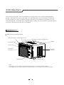
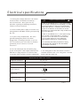
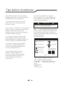
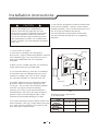
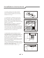
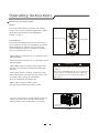
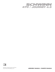
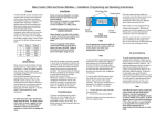
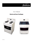
1
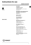
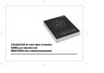
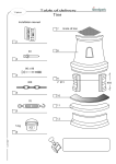
User’s Manual
5,000 BTU Room Air Conditioner
Model: SCA052MWB1
20060323
Table of C ontents
P age
Introduction
2
P arts Identification
2
E lectrical S pecifications
4
T ips B efore Ins tallation
5
Ins tallation Ins tructions
6
Operating Ins tructions
9
C are and Maintenance
13
T roubleshooting G uide
14
Introduc tion
T hank you for choos ing this room air conditioner to cool your home. T his US E AND C AR E MANUAL
provides information neces s ary for the proper care and maintenance of your new room air conditioner.
If properly maintained, your air conditioner will give you many years of trouble free operation. T o avoid
ins tallation difficulties , read ins tructions completely before s tarting. T his manual contains information for the
ins tallation and operation of your room air conditioner.
P art Identific ation
Mec hanic al c ontrol model
Interior Air Outlet
Horizontal Air V ane
V ertical Air V ane
F res h Air Lever (for 8K model only)
C abinet
Air F ilter(Ins ide)
F ront P anel
Interior Air
Inlet G rille
E xterior
Air Inlet
P ower C ord
C ontrol K nob
Note:
T he figures in this manual are bas ed on the external view of a s tandard model.
C ons equently, the s hape may differ from that of the air c onditioner you have s elec ted.
2
E lec tric al s pec ific ations
1. All wiring mus t comply with local and national
electrical codes and mus t be ins talled by a
licens ed electrician. Once you have any
ques tions regarding the following ins tructions ,
contact a licens ed electrician.
E lec tric S hoc k Hazard
If the air conditioner has a s erial plate rating
of 115 volts and up to and including 7.5 amps
the unit maybe on a fus e or circuit breaker
with other devices . However, the maximum
amps of all devices on that fus e or circuit
breaker can not exceed the amps of the fus e
of circuit breaker.
2. C heck available power s upply and res olve any
wiring problems B E F OR E ins talling and operating
this unit.
If the air conditioner has a s erial plate rating
of 115 volts and greater than 7.5 amps it
mus t have its own fus e or circuit breaker,
and no other device or unit s hould be
operated on the fus e or circuit breaker.
3. F or your s afety and protection, this unit is
grounded through the power cord when
plugged into a matching wall outlet. If you are
not s ure whether your wall outlet is properly
grounded, pleas e c ons ult a lic ens ed
elec tric ian.
4. T he wall outlet(3-pin) mus t match the plug
(3-pin) on the power cord s upplied with the unit.
DO NOT us e plug adapters or extens ion cords .
S ee (T able 1) for receptacle and fus e information.
T o avoid the pos s ibility of pers onal injury,
dis connect the power to the unit before
ins talling or s ervicing.
5. T he rating plate on the unit contains electrical
and other technical data. T he rating plate is located
on the right s ide of the unit.
R E C E P T A CL E A ND F US E T Y P E S
C OOLING C AP ACIT Y
!
5K
R ATE D V OLT S
6K
8K
125
AMP S
15
W ALL OUT LE T
F US E S IZE
15
T ime Delay F us e
(or circuit breaker)
P lug type
T able 1
3
T ips before ins tallation
Y our R oom Air C onditioner unit is des igned to
be highly efficient and s ave energy. F ollow thes e
recommendations for greater efficiency.
Y our R oom Air C onditioner was des igned
for eas y ins tallation in a s ingle or double-hung
window. NOT E : T his unit is NOT des igned for
vertical (s lider type) windows .
1. S elect thermos tat s etting that s uits your
comfort needs and leave the thermos tat at
that chos en s etting.
!
C A UT ION
!
T o avoid ins tallation/operating diffic ulties ,
read the ins truc tions thoroughly.
2. T he air filter is very efficient in removing airborne
particles . K eep the air filter clean. T ypically, filter
s hould be cleaned once a month. More
frequent cleaning may be neces s ary depending
on outdoor and indoor air quality.
NOT E :
S ave the s hipping carton and packing
materials for future s torage or trans port of the unit.
P leas e check the contents of the hardware kit
agains t the corres ponding model check lis t, prior to
ins tallation of the unit.
S ee lis ts below.(F ig.1)
3. Us e drapes , curtains , or s hades to keep
direct s unlight from heating your room, but
DO NOT obs truct the air conditioner. Allow air to
circulate around the unit without obs tructions .
Ins tallation Hardware
4. S tart your air conditioner before outdoor
air becomes hot and uncomfortable. T his
avoids an initial period of dis comfort while
the unit is cooling off the room.
3/4"S crews (12)
S eal(1)
2/5"S crews (8)
F oam(1)
T op C hannel(1)
factory ins talled
S ide C urtain R H(1)
S ide C urtain LH(1)
L B racket(2)
5. When outdoor temperature is cool
enough, us e HIG H or L OW F A N
only. T his circulates indoor air, providing
s ome cooling comfort, and utilizes les s
electricity than when operating on a
cooling s etting.
S ide B racket(2)
F ig.1
NOT E : S urplus s c rew(s ) for s pare us e.
Tools Needed for Window Ins tallation
S crew drivers : B oth P hilips and flat head
P ower drill:
1/8 inch diameter drill bit
P encil
Meas uring tape
S cis s ors
C arpenters level
4
Ins tallation ins truc tions
!
C A UT ION
!
B ecaus e the compres s or is located on the
controls s ide of the unit (right s ide), this s ide
will be heavier and more awkward to manipulate.
Inadequate s upport on control s ide of the unit
can res ult in pers onal injury and damage to your
unit and property. T herefore, it is recommended
to have s omeone as s is t you during the ins tallation
of this unit.
1. S elec t the B es t L oc ation
A. Your room air conditioner was des igned to
fit eas ily into a s ingle or double hung window. However,
s ince window des igns vary, it may be neces s ary to
make s ome modifications for s afe and proper
ins tallation.
F. Your unit was des igned to evaporate condens ation
under normal conditions . However, under extreme
humidity conditions , exces s condens ation may caus e
the bas e pan to overflow to the outs ide.
T he unit s hould be ins talled where condens ation
run-off cannot drip on pedes trians or neighboring
properties .
Awning
20"
Min.
12" Min.
B . Make s ure the window and frame are s tructurally
s ound and free from dry and rotted wood.
C . F or maximum efficiency, ins tall the air conditioner
on s ide of the hous e or building which favors more
s hade than s unlight. If the unit is in direct s unlight,
it is advis able to provide an awning over the unit.
D. P rovide s ufficient clearance around the cabinet
to allow for ample air circulation through the unit.
S ee (F ig.2). T he rear of the unit s hould be outdoors
and not in a garage nor ins ide of a building.
K eep unit as far away as pos s ible from obs tacles
and obs tructions and at leas t 30" above the floor or
ground. C urtains and other objects within a room
s hould be prevented from blocking the air flow.
E . B e certain the proper electrical outlet is within reach
of the ins tallation. Us e only a s ingle outlet circuit rated
at 15 amps . All wiring s hould be in accordance with
local and national electrical codes .
.
5
20"
Min.
F ence,
wall, or
other
obs tacle.
30" Min.
S ide
obs truction
G round
F ig.2
Window opening requirements
(s ee table below)
Model
S ize
C abinet s ize
(W*H*D)
Min. Window
opening
Max. Window
opening
5K -6K
8K
17.7" *12.4" *15.7" 18.5" *13.7" *17.7"
21"
22"
35"
36"
Ins tallation ins truc tions
Window ins tallation s tep
14 '' Min
1. If your air conditioner cabinet 18'' wide, it will fit
window openings 21'' to 32'' in wide. Minimum
opening height is 14'' from bottom of s as h to s ill
(F ig. 1).
21'' to 32''
F ig. 1
2. Ins ert the guide panels into the guides of the air
conditioner. F as ten the curtains to the unit with s crews
(F ig. 2).
2/5 '' S crews
F ig. 2
3. C ut the adhes ive-backed s eal s trip the window width.
R emove the backing from the s eal s trip and attach
the s eal s trip to the unders ide of the bottom window.
(F ig. 3)
S eal
F ig. 3
4. Meas ure the ins ide window s ill width and find
the center line as s hown in F ig. 4.
C enter Line
F ig. 4
6
Ins tallation ins truc tions
Inner S ill
O uter S ill
5. Ins tall the L brackets on the outer s ill with the
s hort s ide of the bracket agains t the back of the
inner s ill. Ins tall one L bracket 7.5 to each s ide
of center line. S ee F ig. 5.
C enter Line
3/4'' S crew
3/4'' S crew
B racket
S hort S ide
6. C arefully lift the air conditioner and s lide it into
the open window. Make s ure the bottom guide of
the air conditioner drops into the notches of the L
brackets . When the air conditioner drops into the L
brackets , the air conditioner will be centered in window
opening as s how in F ig. 6.
While s teadying the air conditioner, carefully bring
the window s as h down behind the top channel
of the air conditioner, as s hown in F ig. 7.
F irs t, fix both s ides onto the window s ill with two 3/4
s crews and one 2/5 s crew ( which is uns crewed from
each s ide of the unit). T hen fix top channel to widow
s as h with one 3/4 s crew and fix s ide curtain frames
with four 3/4 s crews as s hown in F ig.6.
7. 5
7. 5
F ig. 5
F oam
3/4
3/4
s crew
3/4
s crew
s crew
3/4
2/5
3/4
Tim e r
Fa n
Mo d e
s crew
s crew
3/4
s crew 3/4 s crew
s crew
Airc o nd itio ne r
F ig. 6
7. If s torm window pres ents interference, fas ten a
2'' wide wood s trip to the inner window s ill acros s
the full width of the s ill. T he wood s trip s hould be thick
enough to rais e the height of the window s ill s o that
the unit can be ins talled without interference from the
s torm window frame, as s how in F ig. 8.
Top of wood s trip s hould be approximately 3/4'' higher
than the s torm window frame to help condens ation to
drain properly to the outs ide.
Ins tall a s econd wood s trip (approximately 6'' long by
1 1/2 ''wide and s ame thicknes s as firs t s trip) in the center
of the outer s ill flus h agains t the back of the inner s ill.
S crew the L brackets into this s trip.
T his will rais e the L bracket as s hown in F ig. 8.
S eal
About 5
L B racket
F ig.7
3/4''C learance
S torm window
frame
Inner s ill
F ig.8
7
Operating Ins truc tions
Mec hanic al c ontrol model
MODE
T he mode knob controls fan s peeds and cooling
s peeds . To s et des ired cooling temperature, s imply
rotate the mode knob dial to the appropriate
s etting. S ee F ig. 9.
T hermos tat knob
Mode knob
T HE R MOS T AT
T he thermos tat automatically controls the cooling
cycle (compres s or) of the air conditioner to maintain
room temperature. However, the fan motor will
continue to operate after the compres s or (cooling
cycle) is completed. S ee F ig.9.
F ig.9
L OW F A N will circulate the air at a minimum s peed
without cooling.
HIG H F A N will circulate the air at a maximum s peed
without cooling.
!
L OW C OOL provides cooling, automatically with
minimum air circulation. R ecommended for nighttime us e.
C A UT ION
!
When us ing F AN control, turn s lowly allowing unit
to adjus t.
HIG H C OOL provides cooling, automatically with
quick cooling or for extremely hot days . Once room
is cooled, reduce s etting to L OW C OOL .
When us ing T HE R MOS T AT , be s ure to allow three
minutes before changing temperature. Adjus ting
too quickly may caus e an overload res ulting in a
blown fus e.
OF F will completely s hut-off the unit.
NOT E : After s etting the mode, allow 3
minutes before s witching to another mode.
F res h A ir V entilation is us ually kept in the clos ed
pos ition. Us e only when clearing s moke and/or
odors from the room. P ull to open. (S ee F ig.10).
F res h Air
V ent Lever
F ig.10
8
C are and Maintenanc e
When s ervicing the air conditioner, be s ure to
turn the mode s witch to the "OF F " pos ition and
dis connect the power cord from the electrical outlet.
1. DO NOT us e gas oline, benzine, thinner or
other chemicals on the air conditioner as thes e
s ubs tances may caus e damage to the paint finis h
and deformation of plas tic parts .
!
C A UT ION
!
DO NOT forget to ins tall the air filter. If the air
conditioner is left to operate without the air filter,
dus t is not removed from the room and may
caus e your air conditioner to fail.
When the air filter inlet grill and cabinet are dirty,
wipe with lukewarm water (below 104 F ).Us e of
mild detergent is recommended.
2. Never attempt to pour water directly in front
of the unit as this will caus e deterioration of
the electrical ins ulation.
C leaning the A ir F ilter
C leaning of A ir F ilter
If the air filter becomes clogged with dus t, air-flow
is obs tructed and reduces efficiency. T he air filter
s hould be cleaned once a month. More frequent
cleaning may be neces s ary depending on outdoor
and indoor air quality.
1. R emove dus t clogged in the filter by
tapping it or vacuum clean it.
2. Was h the filter well with lukewarm water below
40 C (104 F ) while rubbing lightly. To get better
res ults , was h it with s oapy water or a neutral
cleaning agent.
A ir F ilter R emoval
3. R ins e the filter well us ing clean water then
dry completely.
T he air filter on the above models is located
behind the air intake front grill.
E nd-of-S eas on C are
To remove the air filter, gras p the filter handle(tab)
located on the up (center) s ide of the air inlet grille
and s lide the air filter to the up.
1. Operate the fan alone for half a day to dry out
the ins ide of the unit.
To reins tall the air filter, revers e the above
procedure.
3. C lean filter.
2. T urn off power and remove plug from wall s ocket.
4. S tore in a dry location.
9
T roubles hooting G uide
F requently, a problem is minor and a s ervice call may not be neces s ary, us e this troubles hooting guide for a
pos s ible s olution.
P R OB L E M
Air conditioner will
not operate
P O S S IB L E C A US E
No power to the unit.
S UG G E S T E D S O L UT IO N
C heck connection of power cord to
power s ource.
C heck fus e or circuit breaker.
S et MODE knob to pos ition other
than "OF F ".
Inefficient or no cooling
Dirty air filter.
C lean or replace air filter.
Inappropriate capacity
for application.
C heck with dealer to determine proper unit
capacity for application.
B locked air flow.
R emove obs truction from grill or
outdoor louvers .
P ower interruption, s ettings
change too quickly, or
compres s or overload tripped.
Let fan run to res tart compres s or
(in approximately 10 minutes ).
Nois y unit
Loos e parts .
Inadequate s upport.
T ighten loos e parts .
P rovide additional s upport to unit.
Odors
F ormation of mold, mildew, or
algae on wet s urfaces .
R emove drain plug and drain bas e pan.
R eplace drain plug.
C lean unit thoroughly.
W ater dripping outs ide
C ondens ation run-off is normal
during hot and humid weather
Add flexible tubing to redirect water flow.
W ater dripping ins ide
Unit
. is not properly angled to
allow water to drain outs ide.
Unit mus t be ins talled on an angle for proper
condens ation run-off. C heck the unit and
make adjus tments .
Ice or fros t build-up
Low outs ide temperature.
When outdoor temperature is approximately
65 F or below, fros t may form when unit is in
cooling mode. S witch unit to F AN (only)
operation until fros t melts .
Unit air filter is dirty.
R emove and clean filter.
NOT E :
If circuit breaker is tripped repeatedly, or fus e is blown more than once, contact a licens ed technician.
10
© 2006 Sunbeam Products, Inc. doing business as Jarden Consumer Solutions.
All rights reserved. Sunbeam® is a registered trademark of Sunbeam Products,
Inc. used under license. Distributed by Petters Consumer Brands, LLC. 4400 Baker
Road, Minnetonka, MN 55343.
For service, support and warranty information, visit www.sunbeammajorappliances.com or in the US call 1-866-866-6283.