1
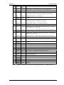
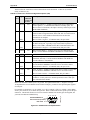
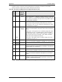
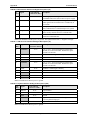
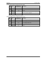
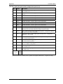
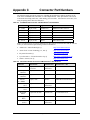
CoreModule™ 800 PCI-104 Single Board Computer QuickStart Guide P/N 5001756A Revision A Notice Page NOTICE No part of this document may be reproduced, transmitted, transcribed, stored in a retrieval system, or translated into any language or computer language, in any form or by any means, electronic, mechanical, magnetic, optical, chemical, manual, or otherwise, without the prior written permission of Ampro Computers, Incorporated. DISCLAIMER Ampro Computers, Incorporated makes no representations or warranties with respect to the contents of this manual or of the associated Ampro products, and specifically disclaims any implied warranties of merchantability or fitness for any particular purpose. Ampro shall under no circumstances be liable for incidental or consequential damages or related expenses resulting from the use of this product, even if it has been notified of the possibility of such damages. Ampro reserves the right to revise this publication from time to time without obligation to notify any person of such revisions. If errors are found, please contact Ampro at the address listed below on the Notice page of this document. TRADEMARKS Ampro and the Ampro logo are registered trademarks, and CoreModule, Little Board, LittleBoard, MightyBoard, MightySystem, MiniModule, ReadyBoard, ReadyBox, ReadyPanel, and ReadySystem are trademarks of Ampro Computers, Inc. All other marks are the property of their respective companies. REVISION HISTORY Revision Reason for Change Date A, A Initial Release Sept/06 Ampro Computers, Incorporated 5215 Hellyer Avenue San Jose, CA 95138-1007 Tel. 408 360-0200 Fax 408 360-0222 www.ampro.com © Copyright 2006, Ampro Computers, Incorporated Audience Assumptions This guide is for the person who designs computer related equipment, including but not limited to hardware and software design and implementation of the same. Ampro Computers, Inc. assumes you are qualified in designing and implementing your hardware designs and its related software into your prototype computer equipment. ii QuickStart Guide CoreModule 800 Contents Chapter 1 Setting Up the CoreModule 800.................................................................................... 1 Using this Guide ................................................................................................................................. 1 Requirements................................................................................................................................. 1 What’s in the Box ........................................................................................................................... 1 Setup Steps........................................................................................................................................ 2 Preparation..................................................................................................................................... 2 Setting Up the Workspace ............................................................................................................. 2 Connecting Cables to the CoreModule 800................................................................................... 3 Connecting Peripherals.................................................................................................................. 7 Connecting Boot Devices............................................................................................................... 7 Connecting the Power Supply........................................................................................................ 8 Applying Power to the CoreModule 800 ........................................................................................ 8 Chapter 2 Installing CoreModule 800 Options ........................................................................... 13 Memory Installation .......................................................................................................................... 13 Tools Required............................................................................................................................. 13 Installation Guidelines.................................................................................................................. 13 Removing the SODIMM ............................................................................................................... 13 Installing the SODIMM ................................................................................................................. 15 Installing Software, Drivers, and Utilities.......................................................................................... 18 Appendix A Technical Support ....................................................................................................... 21 Appendix B I/O Interface Board....................................................................................................... 23 Overview ....................................................................................................................................... 23 I/O Interface Board Layout........................................................................................................... 23 I/O Interface Board Connectors ................................................................................................... 24 Appendix C Connector Part Numbers ............................................................................................ 35 List of Figures Figure 1-1. Figure 1-2. Figure 1-3. Figure 1-4. Figure 1-5. Figure 1-6. Figure 1-7. Figure 1-8. Figure 2-1. Figure 2-2. Figure 2-3. Figure 2-4. Figure B-1. CoreModule 800 Connector Locations ........................................................................... 3 Connector and Pin-1 Locations ...................................................................................... 3 Connecting the IDE and Utility Cables ........................................................................... 4 Connecting Video, Ethernet and Power Cables/Adapter ............................................... 4 Connecting Utility Cables to the I/O Interface Board...................................................... 5 Complete CoreModule 800 Cable Assembly.................................................................. 6 I/O Interface Board Connections .................................................................................... 6 CoreModule 800 Jumper Locations.............................................................................. 11 CoreModule 800 SODIMM Location (Bottom view) ..................................................... 14 Removing SODIMM from Socket ................................................................................. 15 Inserting SODIMM into Socket ..................................................................................... 16 Pressing down on SODIMM ......................................................................................... 17 I/O Interface Board Connectors (Top view).................................................................. 23 List of Tables Table 1-1. CoreModule 800 Jumper Settings ................................................................................. 10 Table 1-2. Power Adapter Cable Wiring ......................................................................................... 11 CoreModule 800 QuickStart Guide iii Contents Table A-1. Technical Support Contact Information..........................................................................21 Table B-1. I/O Interface Board Jumper (JP1) Settings....................................................................23 Table B-2. Utility 1a Interface Pin/Signal Descriptions (J4).............................................................24 Table B-3. Utility 2a Interface Pin/Signal Descriptions (J5).............................................................26 Table B-4. Serial Port 1 Interface Pin/Signal Descriptions (J7).......................................................28 Table B-5. Serial Port 2 (COM2) Interface Pin/Signal Descriptions (J7A) ......................................29 Table B-6. Misc External Interface Pin/Signal Descriptions (J6) .....................................................30 Table B-7. USB Port 0 & 1 Interface Pin/Signal Descriptions (J8) ..................................................30 Table B-8. Keyboard Interface Pin/Signal Descriptions (J9A).........................................................30 Table B-9. Mouse Interface Pin/Signal Descriptions (J9B) .............................................................31 Table B-10. SMBus Interface Pin/Signal Descriptions (J10) ...........................................................31 Table B-11. Floppy Drive Interface Pin/Signal Descriptions (J11) ..................................................32 Table B-12. Parallel Port (LPT) Interface Pin/Signal Descriptions (J12) .........................................33 Table C-1. CoreModule 800 Connector and Manufacturer’s Part Numbers ...................................35 Table C-2. I/O Inteface Board Connector and Manufacturer’s Part Numbers.................................35 iv QuickStart Guide CoreModule 800 Chapter 1 Setting Up the CoreModule 800 Using this Guide This guide provides the most efficient way to set up your CoreModule™ 800 SBC (single board computer). The instructions provided in this guide include: • Removing the CoreModule 800 from the shipping container and inventorying the accessories • Connecting cables to the CoreModule 800 SBC • Connecting the I/O Board, Cable Adapter Board, peripherals, boot devices, and power supply to the CoreModule • Powering up the CoreModule 800 SBC Information not provided in this QuickStart Guide includes: • CoreModule 800 Specifications • Environmental requirements • CoreModule 800 connector/pin numbers and definitions • Supplied software use and programming considerations Requirements The following peripherals and boot devices are not provided in the QuickStart Kit, but are needed to make full use of the CoreModule 800. • Peripherals (Customer provided): ♦ PS/2 Keyboard ♦ PS/2 Mouse ♦ CRT (VGA) Monitor • Power Supply (Customer provided): ♦ AT or +5V lab power supply – Typically, an AT power supply is required to provide power to the CoreModule 800 and its associated peripherals. • Boot Devices (one or more - Customer provided): ♦ Floppy Disk drive ♦ CD-ROM ♦ IDE hard disk drive • Optional Devices/Connections (Customer provided): ♦ LVDS Flat Panel ♦ Ethernet connection (Ampro provided (RJ-45) board with magnetics) ♦ USB devices What’s in the Box Refer to the QuickStart Kit Contents Sheet for a list of the items in the shipping container. CoreModule 800 QuickStart Guide 1 Chapter 1 Setting Up the CoreModule 800 Setup Steps It is important to follow the setup steps in this section in the exact order listed here, but skip any steps that do not apply to your situation. References are provided to chapters within this guide or other Ampro guides, for more information about installation and use of this CoreModule 800. Preparation • Locate the QuickStart Kit Contents Sheet 1) Open shipping box • Unpack the contents of the shipping box • Verify the contents of the shipping box against the QuickStart Contents Sheet included with your CoreModule 800 shipping box. 2) Verify Contents • If anything is missing or damaged, call your sales representative or Tech Support. 3) Support Documentation (CoreModule 800 Documentation and Support Software CD-ROM ) CoreModule 800 QuickStart Guide This document describes how to setup, install, and power up the CoreModule 800 found in the QuickStart Kit and is provided on the CoreModule 800 Documentation and Support Software (Doc & SW) CD-ROM as a PDF file. CoreModule 800 Reference Manual This document describes the CoreModule 800 and provides detailed reference information for your CoreModule 800 and is located on the CoreModule 800 Documentation and Support Software (Doc & SW) CD-ROM as a PDF file. Setting Up the Workspace CAUTION To prevent damage to the CoreModule 800 SBC, do not handle the board until you have followed good Electrostatic Discharge precautions. Always touch a grounded, unpainted metal surface before touching the CoreModule 800 SBC or any of the components on the board. Always use an anti-static wrist strap connected to a grounding mat, which has staticdissipating characteristics and attached to earth ground. 4) Select workbench location • The workbench location should have a non-conductive, static-free mat (or the equivalent) to place the CoreModule 800, I/O Interface Board, and I/O Cable Adapter Board on for setup and operation (including the connection of the power supply, peripherals, and support devices). 5) Connect an ESD strap to your body • Connect an ESD strap between your body (wrist or ankle) and ground on the static-free mat. 6) Unpack CoreModule 800 If you do not have your own ESD strap, an ESD kit is provided in the QuickStart Kit with an anti-static wrist strap. • Remove the CoreModule 800 from its protective plastic case and place it on a non-conductive, static-free work surface. • Remove the I/O Interface Board (I/O Board) and the I/O Cable Adapter Board (I/O Adapter) from the respective protective container (usually in the cable bag) and place each one on a non-conductive, static-free work surface. 2 QuickStart Guide CoreModule 800 Chapter 1 Setting Up the CoreModule 800 Connecting Cables to the CoreModule 800 CoreModule 800 Utility 2 (J5) Daughter Power Board Utility 1 (J4) CM800QkS_03a Connect the cables provided with the CoreModule 800 QuickStart Kit to the respective connectors on the CoreModule 800 SBC. Skip any cable(s) that do not apply to your situation. Video (J1) IDE (J6) Ethernet (J3) Power In (J7) Figure 1-1. CoreModule 800 Connector Locations Utility 1 (J4) Utility 2 (J5) J4 J5 D9 D10 JP3 D17 JP4 Video (J1) U1 U2 J1 J9 Ethernet (J3) U9 U11 J3 U26 Q1 J8 Q6 Daughter Power Board U5 U13 U12 Q2 Q3 J6 J7 Power In (J7) JP1 IDE (J6) JP2 CM800QkS_01a Q4 Figure 1-2. Connector and Pin-1 Locations NOTE CoreModule 800 Pin-1 is shown as a black pin (square or circle) in all connectors and jumpers in all illustrations. A small arrow head may also indicate pin-1. QuickStart Guide 3 Chapter 1 Setting Up the CoreModule 800 Skip any steps that do not apply to your situation. • Connect Utility 1 cable to J4 on the CoreModule 800 as shown in Figure 1-3. 1) Connect Utility 1 & 2 Cables • Connect Utility 2 cable to J5 on the CoreModule 800 as shown in Figure 1-3. Utility 1 and 2 cables are identical and can be interchanged. • Connect the IDE cable to J6 on the CoreModule 800 as shown in Figure 1-3. 2) Connect IDE cable Connect to I/O Board (J5) Connect to I/O Board (J4) Utility 2 Cable & Connectors Utility 1 Cable & Connectors J5 J4 CM800QkS_04a IDE Device Cable and Connectors (J6) 44-pin Connector CM800QkS_05a Figure 1-3. Connecting the IDE and Utility Cables Video Cable & Connectors (J1) Standard power connector for hard disk drives (HDD) found on AT or ATX power supplies. Ethernet RJ45 Adapter (J3) Power Adapter Cable & Connectors (J7) Figure 1-4. Connecting Video, Ethernet and Power Cables/Adapter 4 QuickStart Guide CoreModule 800 Chapter 1 Setting Up the CoreModule 800 3) Connect the Video Cable • Connect the Video cable to the Video connector (J1) on the CoreModule 800 as shown in Figure 1-4. Pin-1 4) Connect Power Adapter Cable • Connect the Power Adapter Cable to the Power In connector (J7) on the CoreModule 800 as shown in Figure 1-4. See Table 1-2 for Power Adapter Cable wiring and pin connections. 5) Connect the Ethernet Adapter board • Connect the Ethernet adapter board provided in the QuickStart Kit to the Ethernet connector (J3) on the CoreModule 800 as shown in Figure 1-4. Refer to the CoreModule 800 I/O Interface Design Library on the CoreModule 800 Doc & SW CD-ROM for more information. • Connect free end of Utility 1 Cable on the CoreModule 800 to J4 on the I/O Board as shown in Figures 1-5 and 1-6. 6) Connect Utility Cables 1 & 2 to the I/O Board • Connect free end of Utility 2 Cable on the CoreModule 800 to J5 on the I/O Board as shown in Figures 1-5 and 1-6. 7) Connect Floppy Drive Cable • Connect a standard 34-pin Floppy drive cable to the Floppy drive port (J11) on the I/O Board. The floppy drive interface (J11) is shared with the Parallel (LPT1) interface (J12), so you can only use one of these connectors at a time on the I/O Board. I/O Interface Board (I/O Board) Utility 1a (J4) Connect Utility 1 cable between J4 (Utility 1) on CoreModule 800 and J4 (Utility 1a) on the I/O Board. Floppy Disk Drive (FDD) Interface (J11) Connect Utility 2 cable between J5 (Utility 2) on CoreModule 800 and J5 (Utility 2a) on the I/O Board. CM800QkS_06a Utility 2a (J5) Figure 1-5. Connecting Utility Cables to the I/O Interface Board CoreModule 800 QuickStart Guide 5 Chapter 1 Setting Up the CoreModule 800 I/O Interface Board (I/O Board) Utility 1a Connector (J4) Utility 1 Cable connected between J4 on I/O Board and J4 on CoreModule 800 Utility 2a Connector (J5) Floppy Disk Drive (FDD) Cable & Connectors (J11) Utility 2 Cable connected between J5 on I/O Board and J5 on CoreModule 800 Utility 2 Connector (J5) Utility 1 Connector (J4) Video Cable & Connectors (J1) IDE Cable & Connectors (J6) (Second IDE connector not shown for simplicity.) Ethernet (RJ45) Adapter Board (J3) CM800QkS_07a CoreModule 800 Power In Cable & Connectors (J7) Figure 1-6. Complete CoreModule 800 Cable Assembly Power Button Switch (SW1) Serial Ports 1 & 2 (J7A/B) PS/2 Keyboard/Mouse (J9A/B) Reset Switch (SW2) USB Ports 0 & 1 (J8A/B) Serial TX/TTL Jumper (JP1) SMBus (J10) Parallel (LPT1) Port (J12) Utility 1a (J4) Utility 2a (J5) I/O Interface Board (I/O Board) CM800QkS_06b Floppy Disk Drive (FDD) Interface (J11) Figure 1-7. I/O Interface Board Connections 6 QuickStart Guide CoreModule 800 Chapter 1 Setting Up the CoreModule 800 Connecting Peripherals 8) Connect peripheral I/O devices to the I/O Board. This includes the keyboard, mouse, and CRT. Skip any devices that are not applicable to your situation. • Connect the keyboard to the keyboard connector (J9A) on the I/O Board (lower connection). Or, Connect a USB keyboard to one of the USB ports on the I/O Board. • Connect the mouse to the PS/2 connector (J9B) on the I/O Board. Or, Connect a USB mouse to one of the USB ports on the I/O Board. • Connect the CRT (VGA) monitor cable to the standard 15-pin Video connector from J1 on the CoreModule 800. Connecting Boot Devices 9) Connect OS boot device (s) • There are four device options for connecting an (OS) boot device to the CoreModule 800: a. Connect a floppy disk drive (FDD) to the floppy drive cable on the floppy port connector (J11) on the I/O Board. See Step 7. Or, Connect a USB floppy drive to one of the USB ports on the I/O Board. b. Connect an IDE hard disk drive (HDD) to one of the free connectors on the IDE cable from J6 on the CoreModule 800. • Ampro does not recommend using a preinstalled OS on a hard disk drive to boot and load the operating system. See Note with Step 21. Or, Connect a USB hard disk drive to one of the USB ports on the I/O Board. c. Connect a CD-ROM drive to the available connector on the IDE cable from J6 on the CoreModule 800. Or, Connect a USB CD-ROM drive to one of the USB ports on the I/O Board (USB0 is lower connector). Ethernet Connection NOTE CoreModule 800 d. Connect an Ethernet cable to Ethernet port (J3) for the PXE server, if you are using the LAN Boot feature. Refer to Steps 17, 18, 19d, 19e, 19f and the LAN Boot Note at the end of this chapter. For the most current Hardware and BIOS Information, refer to the CoreModule 800 Hardware Release Notes provided as hard copy in the shipping container. QuickStart Guide 7 Chapter 1 Setting Up the CoreModule 800 Connecting the Power Supply 12) Connect the Power Supply • Connect the AT power supply to the power adapter cable connected to J7 on the CoreModule 800. The available connector mates with the standard power connectors used for hard disk drives on AT or ATX power supplies. 13) Connect all support devices to the power supply • Ensure all of the support devices you have plugged into the connectors (except the CRT (VGA) from the CoreModule 800 have good power connections to the AT power supply. 14) Check/Set jumper settings • Check or set the jumpers on the CoreModule 800 and the I/O Board. Refer to Table 1-1 and Figure 1-8 for CoreModule 800 jumper settings. Refer to Table B-1 and Figure B-1 for the I/O Board settings. Applying Power to the CoreModule 800 15) Check/Set the Power Supply Input Voltage • If the power supply uses auto-ranging operation at 50/60 Hz, skip this step. • Check the input voltage switch on the power supply located on the rear of the supply just below the power connector. The input voltage switch typically has two positions: 115 or 230 volts – 115 volts is typically the default position. 16) Power up the CoreModule 800 a. Plug the CRT monitor’s power cord into an AC outlet and turn on the monitor. b. Plug the AT power supply’s power cord into the AC outlet. 17) Verify the CoreModule 800 powers-up satisfactorily c. Turn the AT power supply’s power switch to On before continuing. • Verify the CoreModule 800 passes POST successfully • If a bootable device, the LAN Boot image, or the desired operating system is not loaded on one of the boot devices (floppy drive or CDROM) prior to power up, you will see an error message Reboot and Select proper Boot device, or Insert Boot Media in selected Boot device and press a key near the end of the boot process. The boot process stops until you intervene, by selecting from: ♦ Reboot the system and go to Step 18 (Enter BIOS Setup), or a. Turn off the power switch on the power supply. b. Connect a bootable device to the CoreModule 800, reapply power to the system, which reboots the system, and then skip to Step 18 or 20. NOTE 8 Ampro does not recommend using a hard disk drive with a preinstalled OS from another model computer to boot the CoreModule 800. This has proven to cause problems or provide unreliable operation. Use a bootable device (floppy or CD-ROM) to load the desired OS onto the hard drive and then the drivers, while attached to the Core Module 800. See Step 20. QuickStart Guide CoreModule 800 Chapter 1 Setting Up the CoreModule 800 18) Enter BIOS Setup • Press the <Del> key early in the boot process to enter BIOS Setup. • Use BIOS Setup during the initial boot to set the desired options (time and date, alter the boot order for the floppy drive, CD-ROM, hard disk drive, or select Network: (LAN Boot), etc.). • Refer to Step 19 to alter the boot sequence, while in BIOS Setup. 19) Alter Boot Order, only if needed. • If you need to alter the boot sequence to select a bootable device, use the sub-steps listed here and refer to the Hardware Release Notes. The sub-steps listed here show you how to change the Boot Sequence while in the BIOS Setup Utility. a) Select the Boot menu and scroll down to Boot Device Priority as shown in the figure to the right. BIOS Set Main Advanced PCIPnP Boot Boot Settings Boot Settings Configuration Boot Device Priority b) Press <Enter> on Boot Device Priority and a menu similar to the one shown to the right appears. This example assumes 1st Boot Device is a 3 ½" floppy drive, 2nd Boot Device is an IDE HDD, 3rd Boot Device is an IDE CD-ROM, and the 4th Boot Device is Network (Ethernet - LAN Boot). c) Scroll to 1st Boot Device and press <Enter> key. The Options list appears with all of the connected devices listed in the menu similar to the one shown to the right. d) To move the CD-ROM up in the Boot Order. NOTE You can also use the F11 key early in the Boot process to access the BBS (BIOS Boot Specification) popup menu to change the boot order. Follow the instructions on screen. e) Check settings, Save Changes and Exit (This step reboots the system). BIOS Set Main Advanced PCIPnP Boot Boot Device Priority 1st Boot Device 2nd Boot Device 3rd Boot Device 4th Boot Device [1st Floppy Drive [HDD: Mfg, Model [CD/DVD: Mfg, Model [Network: IBA FE Slo ] ] ] ] Options 1st Floppy Drive HDD: Mfg, Model CD/DVD: Mfg, Model Network: IBA FE Slot 0100 v4118 Disabled • Scroll down to CD/DVD: Mfg, Model and press the <Enter> key. The CD-ROM swaps place with the 1st Floppy Drive, putting the CD-ROM, or any device you select, including Network, in the 1st Boot Device position, while putting the 1st Floppy Drive in the 3rd Boot Device position. • If you select Disabled, the 1st Floppy Drive moves to the 4th position (last), labeled Disabled, while all other devices move up in the Boot order. • For more information, refer to the BIOS Chapter in the CoreModule 800 Reference Manual. • Check the other settings in the BIOS before exiting BIOS Setup to save changes. • If you are using the LAN Boot feature, refer to the step f. CoreModule 800 QuickStart Guide 9 Chapter 1 Setting Up the CoreModule 800 f) For LAN Boot, go to PXE Boot Agent BIOS Setup after rebooting • Enter PXE BIOS by pressing Ctrl + S, when you see the following prompt appear on screen: Initializing Intel (R) Boot Agent FE v4.x.xx PXE v2.0 Build 084 (WfM 2.0) Press Ctrl + S to enter the setup Menu.. • Make the necessary changes in the PXE BIOS Setup before saving changes. Refer to Appendix C of the CoreModule 800 Reference Manual for more information. 20) Install the desired Operating System (OS) • Use the LAN Boot feature to load the boot (OS) image onto the hard disk drive, or other media. (See Note below) Or • Locate the desired Operating System (OS) diskette(s) or CD-ROM and follow the manufacturer’s instructions for installing the OS and the necessary drivers. For Windows Operating Systems, most of the necessary drivers are found on the manufacturer’s installation CD-ROM. For non-Windows Operating Systems, some or all of the necessary drivers may be found on the manufacturer’s diskette(s) or CD-ROM. • If you require drivers that are not available on the OS manufacturer’s diskette(s) or CD-ROM, refer to Installing Software, Drivers, and Utilities in Chapter 2 and the software subdirectory on the CoreModule 800 Doc & SW CD-ROM for the files and instructions. NOTE The CoreModule 800 ships from the factory configured only for CRT support. Ampro provides LCD/TFT support for flat panels with specific resolutions. Refer to the CoreModule 800 Reference Manual, the Release Notes, and Virtual Technician at http://ampro.custhelp.com for instructions and additional information when customizing the BIOS to a particular flat panel. NOTE LAN Boot Feature – The LAN Boot process puts the Ethernet connection at the top of the boot order, but it requires more than just selecting the correct BIOS Setup options. You will also need a PXE server with its tools and utilities, which Ampro does not provide. For the PXE BIOS settings and more information refer to Appendix C of the CoreModule 800 Reference Manual. See Figures 1-1, 1-2, and 1-8 for the CoreModule 800 jumper locations. For the I/O Board jumper settings refer to Table B-1 and Figures 1-7 and B-1 for the I/O Board jumper location. Table 1-1. CoreModule 800 Jumper Settings Jumper # Installed Removed/Enabled JP1 – CMOS Normal/Clear Clear (1-2) Normal (Removed) Default JP2 – Serial 2 RS-485 Termination Enable Termination (1-2) Disable Termination (Removed) Default JP3 – Serial 1 RS-485 Termination Enable Termination (1-2) Disable Termination (Removed) Default JP4 – LVDS Flat Panel Voltage Select Enable +3.3V (pins 1-2) (Default) Enable +5V (pins 2-3) Notes: Jumpers (or shunts) use 2 mm spacing. A jumper that is removed may be placed on one of the jumper pins for safe keeping. 10 QuickStart Guide CoreModule 800 Chapter 1 Setting Up the CoreModule 800 J4 Flat Panel Voltage Select (JP4) J5 D9 D10 JP3 D17 JP4 U1 Serial 1 RS-485 Termination (JP3) U2 J1 J9 U9 U11 J3 U26 Q1 J8 Q6 U5 U13 U12 Q2 Q3 J6 J7 JP1 CMOS Normal/ Clear (JP1) JP2 Serial 2 RS-485 Termination (JP2) CM800QkS_01b Q4 Figure 1-8. CoreModule 800 Jumper Locations The power adapter cable is connected between the Power In connector (J7) and the power supply connector. See Steps 5 and 12. Table 1-2. Power Adapter Cable Wiring Wire Color Four Pin # To Ten Pin # Signal Yellow P-1 To P-4 +12V Black P-2 To P-1 GND Black P-3 To P-7 GND Black P-3 To P-9 GND Red P-4 To P-2 +5V Red P-4 To P-8 +5V Red P-4 To P-10 +5V P-3 Key – – – Note: The shaded area denotes power or ground. CoreModule 800 QuickStart Guide 11 Chapter 1 12 Setting Up the CoreModule 800 QuickStart Guide CoreModule 800 Chapter 2 Installing CoreModule 800 Options The procedures in the first part of this chapter describe how to install or remove the CoreModule 800 SBC (Single Board Computer) options onto or from the board, including the SODIMM card. Brief instructions for loading supported Operating Systems and accessing the CoreModule 800 Doc & SW (Documentation and Software) CD-ROM are also provided at the end of this chapter. Memory Installation The CoreModule 800 uses a single SODIMM socket available on the underside of the board. The CoreModule 800 supports PC 2700 DDR 333 (333 Mbps, 166 MHz) or PC 2100 DDR 266 (266 Mbps, 133 MHz), +2.5V, 200-pin, DDR RAM SODIMM. Ampro recommends using PC 2700 DDR 333 (333 Mbps, 166 MHz, 6 ns), +2.5V, 200-pin, DDR RAM SODIMM for maximum performance. The CoreModule will operate acceptably with a PC 2100 DDR 266 (266 Mbps, 133 MHz, 7.5 ns) SODIMM. NOTE Tools Required Use an anti-static service kit (or the equivalent) to remove or install the SODIMM. An anti-static service kit should include a static-dissipating work surface, a chassis clip lead, and a wrist or ankle strap. Installation Guidelines • When handling a SODIMM, observe anti-static discharge precautions to avoid damage. • The CoreModule 800 uses PC 2700 DDR 333 (166 MHz) or PC 2100 DDR 266 (133 MHz), RAM SODIMMs, which are electrically different from SDR (Single Stroke) SODIMMs. • The following DDR SODIMMs sizes are available from Ampro: 128 MB, 256 MB, 512 MB, or 1 GB. • The CoreModule 800 supports up to 1 GB of memory in the SODIMM socket. Removing the SODIMM Use this procedure to remove the SODIMM from the SODIMM socket on the CoreModule 800. 1. Prepare the CoreModule 800 for SODIMM removal: ♦ If the CoreModule 800 is already prepared for SODIMM removal, with the power turned off, and the power cord disconnected, skip to Step 4. ♦ If the CoreModule 800 is operating, power down the system and continue with next step. CAUTION To prevent damage to the CoreModule 800 and the SODIMM, ensure the power switch on the AT or ATX power supply is turned off and the power cord has been removed from the AC power source. The typical ATX power supply will continue to provide standby current to the board until the power cord is disconnected. 2. Disconnect the ATX or AT power supply’s power cord from the AC power source. CoreModule 800 QuickStart Guide 13 Chapter 2 Installing CoreModule 800 Options To prevent damage to the CoreModule 800 or the SODIMM, do not touch the either one until you have discharged yourself and have followed good Electrostatic Discharge principals. The CoreModule 800 and the SODIMM are sensitive to static electricity and can be easily damaged by improper handling. Do the following when handling either one: CAUTION Use an anti-static wrist/ankle strap and a grounding mat connected to ground. Before you touch the CoreModule 800 or SODIMM, touch a grounded, unpainted metal surface to discharge any static electricity. 3. Disconnect any cables that would prevent you from turning the CoreModule 800 over exposing the bottom of the board. 4. Turn the CoreModule 800 over to access the bottom of the board and lay it on a flat anti-static surface. See Figures 2-1 and 2-2. CM800QkS_08a 5. Locate the SODIMM socket (J22) on the bottom of the CoreModule 800. See Figure 2-1. U4 D3 D2 Y3 D1 Q14 Q15 U16 U18 U15 U25 D7 F1 U22 Q7 Q5 L9 DDR SODIMM U21 Y2 U6 J13 U10 DDR SODIMM Socket (J13) Retaining Latches (2) Figure 2-1. CoreModule 800 SODIMM Location (Bottom view) 6. Open both retaining latches to release the SODIMM from the socket. See Figure 2-1. The SODIMM will spring up to a 45° angle to the board once you open both retaining latches. If the SODIMM does not spring up to a 45° angle, then the retaining latches have not released the SODIMM from the socket. See Figure 2-2. 7. Using the card edges, lift the SODIMM completely away from the socket. See Figure 2-2. 8. Place the SODIMM on an anti-static surface or in an anti-static bag. NOTE 14 If you remove the SODIMM and restore power without a SODIMM installed, you will not see a display and your system will not work properly. QuickStart Guide CoreModule 800 Chapter 2 Installing CoreModule 800 Options DDR SODIMM DDR SODIMM Socket (J13) CM800QkS_09a 45° Angle Figure 2-2. Removing SODIMM from Socket Installing the SODIMM If you want to install a different size SODIMM or replace the existing SODIMM, refer to the following procedure. 1. Prepare the CoreModule 800 for SODIMM installation: ♦ If the CoreModule 800 is already prepared for SODIMM installation, with the power turned off, the power cord disconnected, and an empty SODIMM socket, skip to Step 4. ♦ If the CoreModule 800 is operating, power down the system and continue with next step. CAUTION To prevent damage to the CoreModule 800 and the SODIMM, ensure the power switch on the power supply is turned off and the power cord has been removed from the power source. The typical ATX power supply will continue to provide standby current to the board until the power cord is disconnected. 2. Disconnect the ATX or AT power supply’s power cord from the AC power source. CAUTION To prevent damage to the CoreModule 800 or the SODIMM, do not touch the either one until you have discharged yourself and have followed good Electrostatic Discharge principals. The CoreModule 800 and the SODIMM are sensitive to static electricity and can be easily damaged by improper handling. Do the following when handling either one: Use an anti-static wrist/ankle strap and a grounding mat connected to ground. Leave the SODIMM in the anti-static bag until you are ready to install it. Before you touch the CoreModule 800 or SODIMM, touch a grounded, unpainted metal surface to discharge any static electricity. 3. Disconnect any cables that would prevent you from turning the CoreModule 800 over exposing the bottom of the board. CoreModule 800 QuickStart Guide 15 Chapter 2 Installing CoreModule 800 Options 4. Turn the CoreModule 800 over to access the bottom of the board and lay it on a flat anti-static surface. See Figures 2-1 and 2-3. 5. Remove the existing SODIMM from the SODIMM socket before continuing. Refer to the Step 4 in the proceeding procedure, Removing the SODIMM, and follow the remaining steps in that procedure before continuing with the next step in this procedure. 6. Remove the SODIMM from the anti-static surface or the protective bag, handling the SODIMM by the edges. Ampro recommends using PC 2700 DDR 333 (333 Mbps, 166 MHz, 6 ns), +2.5V, 200-pin, DDR RAM SODIMM for maximum performance. The PC 2100 DDR 266 (266 MBps, 133 MHz) SODIMM will operate acceptably. NOTE 7. Ensure there is nothing in the SODIMM socket that would prevent the installation. 8. Insert the SODIMM into the socket at 45° angle to the bottom of the CoreModule 800 with the components facing up. See Figure 2-3. The SODIMM card edge and socket are keyed to install into the socket in only one orientation. DDR SODIMM Retaining Latches (2) CM800QkS_10a 45° Angle Key(Hidden) Alignment Notch Figure 2-3. Inserting SODIMM into Socket 9. Press the edges of the SODIMM down between the latches, until the latches snap into place. See Figure 2-4. The latches should open to accept the SODIMM without any resistance. If you encounter any resistance, you may not have inserted the SODIMM far enough into the socket. 16 QuickStart Guide CoreModule 800 Chapter 2 Installing CoreModule 800 Options Press down on SODIMM at both corners until you hear a snap. CM800QkS_11a DDR SODIMM Figure 2-4. Pressing down on SODIMM 10. If the retaining latches do not close completely on the SODIMM, remove it and repeat Steps 7 to 9. 11. Turn the CoreModule 800 back over onto the bottom of the board, placing it on the work surface. 12. Reconnect any cables you disconnected earlier and verify all other connections to the CoreModule 800 are still connected. 13. Reconnect the ATX or AT power supply’s power cord to the AC power source. 14. Restore power to the CoreModule 800 and observe the boot screen for new memory recognition. If the system does not boot or there is a problem recognizing the new memory, the new SODIMM could be defective or the SODIMM was not properly installed or recognized. CoreModule 800 QuickStart Guide 17 Chapter 2 Installing CoreModule 800 Options Installing Software, Drivers, and Utilities To install the operating system and respective software drivers, refer to the following procedure. 1. Install the desired operating system (OS) and related drivers from the source files (LAN Boot) or from the manufacturer’s diskette(s) or CD-ROM. If you are using the LAN Boot feature to load the boot (OS) image, skip the remaining Steps that do not apply. ♦ Follow the manufacturer’s instructions to install the desired OS and respective drivers. ♦ For Windows Operating Systems, some of the necessary drivers may be found on the manufacturer’s installation diskette or CD-ROM. If more software drivers are needed, refer to the CoreModule 800 Doc & SW CD-ROM. ♦ For other Operating Systems, some or all of the necessary drivers may be found on the manufacturer’s installation diskette(s) or CD-ROM. If not, refer to the CoreModule 800 Doc & SW CD-ROM. 2. Run the CoreModule 800 Doc & SW CD-ROM to access the documentation, various utilities, and OS drivers not on the manufacturer’s diskette(s) or CD-ROM. The CoreModule 800 Doc & SW CD-ROM will operate on any Windows PC, allowing you to view, download, or print the contents of the CD-ROM. This includes the: ♦ CoreModule 800 QuickStart Guide ♦ CoreModule 800 Reference Manual ♦ CoreModule 800 Software Release Notes ♦ Software drivers ♦ Various utilities and code examples NOTE You must have an Internet browser to view the main menu and make selections (examples: Microsoft Internet Explorer 4.x, or greater, Netscape Navigator version 4.x, or greater, or the equivalent on a PC). Software download links are provided for Adobe Acrobat Reader version 4.x or greater to view the manuals and documents. An Internet connection is required for the Adobe Acrobat link or access to the Ampro web site. The CoreModule 800 Doc & SW CD-ROM should auto-start, but if it does not, go to the root level of the CD-ROM and locate the index.htm by: a. Selecting Run from the Start menu in any Windows PC. b. Browsing the contents of the CD-ROM until you find the index.htm at the root level. c. Select this file and press OK to start the CD-ROM. The CD-ROM starts and opens the main menu of the CD-ROM. 3. Select from the directories as shown below: 18 ♦ CoreModule 800 Documentation (CoreModule 800 Reference Manual, QuickStart Guide, Software Release Notes) ♦ CoreModule 800 Software (Supported operating system (OS) Board Support Packages (BSPs), drivers, and code examples) ♦ CoreModule 800 SBC Interface Design Library (includes the PCB layout, schematic, and BOM/AVL for I/O Interface board, and Ethernet Interface board). QuickStart Guide CoreModule 800 Chapter 2 Installing CoreModule 800 Options There are directories and subdirectories under these topics that should provide you with the needed manuals, utilities, and tools not explained earlier. 4. Install any special OS drivers not found on the manufacturer’s diskette(s) or CD-ROM. Refer to the directories and subdirectories on the CoreModule 800 Doc & SW CD-ROM for instructions when installing the drivers for the desired OS. If the desired drivers can not be found, contact Ampro through the Virtual Technician on the web site with a request for the driver(s). Refer to the Appendix A, Technical Support for more information. 5. Install any utilities or other development tools you may need from the CoreModule 800 Doc & SW CD-ROM. Refer to the directories on the CoreModule 800 Doc & SW CD-ROM for instructions on installing and using the utilities or development tools for the desired OS. CoreModule 800 QuickStart Guide 19 Chapter 2 20 Installing CoreModule 800 Options QuickStart Guide CoreModule 800 Appendix A Technical Support Ampro Computers, Inc. provides a number of methods for contacting Technical Support listed below in Table A-1. Requests for support through the Virtual Technician are given the highest priority, and usually will be addressed within one working day. • Ampro Virtual Technician – This is a comprehensive support center designed to meet all your technical needs. This service is free and available 24 hours a day through the Ampro web site at http://ampro.custhelp.com. This includes a searchable database of Frequently Asked Questions, which will help you with the common information requested by most customers. This is a good source of information to look at first for your technical solutions. However, you must register online if you wish to use the "Ask a Question" feature. • Personal Assistance – You may also request personal assistance by creating a Virtual Technical account and then going to the "Ask a Question" feature. Requests can be submitted 24 hours a day, 7 days a week. You will receive immediate confirmation that your request has been entered. Once you have submitted your request, you must log in to go to the "My Stuff" area where you can check status, update your request, and access other features. • Embedded Design Resource Center – This service is also free and available 24 hours a day at the Ampro web site at http://www.ampro.com. However, you must be registered before you can login to access this service. The Embedded Design Resource Center was created as a resource for embedded system developers to share Ampro's knowledge, insight, and expertise gained from years of experience. This page contains links to White Papers, Specifications, and additional technical information. Table A-1. Technical Support Contact Information Method Contact Information Virtual Technician http://ampro.custhelp.com Web Site http://www.ampro.com Standard Mail Ampro Computers, Incorporated 5215 Hellyer Avenue San Jose, CA 95138-1007, USA CoreModule 800 QuickStart Guide 21 Appendix A 22 Technical Support QuickStart Guide CoreModule 800 Appendix B I/O Interface Board Overview The I/O Interface Board (I/O Board) provides the I/O device connections and interface to the CoreModule 800 in the Utility connectors (J4, J5) on the I/O Interface Board. The I/O Interface Board (I/O Board) provides the I/O connections for the keyboard, mouse, floppy/parallel port, serial ports (2) and USB ports (2). The I/O Board also provides the Infrared (IR) transceiver for IrDA connections, a battery socket with Lithium battery, PC "Beep" speaker, a reset switch and power on switch. I/O Interface Board Layout Serial 1 & 2 (J7A/B) SMBus (J10) (Serial 1 Lower) Misc (J6) Reset Switch (SW2) Power Button Switch (SW1) Reset PwrBtn Hard Disk Drive Activity LED (D1) J10 J6 D3 D1 U3 SW2 JP1 U2 SW1 J7 J4 Power On LED (D3) Bat1 J9 Keyboard (Lower) & Mouse (J9A/B) F1 Utility 1a (J4) Serial 2 TX/TTL Jumper (JP1) Infrared (IrDA) Transceiver (U2) LS1 U4 U1 D2 J5 J12 FDD Utility 2a (J5) J8 USB 0 (Lower) & USB 1 (J8A/B) J11 Fuse (F1) PC “Beep” Speaker (LS1) Battery Socket (Bat1) Floppy Disk Drive (J11) CM800QkS_12a Thermal Monitor (U3) Figure B-1. I/O Interface Board Connectors (Top view) NOTE If you need more information concerning the I/O Board than is provided in this Appendix, refer to the I/O Interface Design Library on the CoreModule 800 Doc & SW CD-ROM for a schematic, BOM, and AVL. Table B-1. I/O Interface Board Jumper (JP1) Settings Jumper # Installed Removed/Enabled JP1 – Serial 2 TX/TTL Jumper (onboard) Normal (Default) TX signal (pins 1-2) to Serial Port 2 (J4-3) TTL signal (pins 2-3) to Serial Port 2 (J4-3) NOTE CoreModule 800 Pin-1 is shown as a black pin (square or circle) in all connectors and jumpers in all illustrations. A small diamond may also indicate pin-1. QuickStart Guide 23 Appendix B I/O Interface Board I/O Interface Board Connectors Table B-2 lists the interface between Utility 1a (J4) and the other connectors/devices on the I/O Board. Table B-2. Utility 1a Interface Pin/Signal Descriptions (J4) J4 Signal Pin # Pin # On- Description board 1 J7-1 Data Carrier Detect 0 – Indicates external serial device is detecting a carrier signal (i.e., a communication channel is currently open). In direct connect environments, this is be driven by DTR0 as part of the DTR0/DSR0 handshake. DCD0* (Serial 1/ COM1) 2 DSR0* J7-6 Data Set Ready 0 – Indicates external serial device is powered, initialized, and ready. Used as hardware handshake with DTR0 for overall readiness to communicate. 3 RXD0 J7-2 Receive Data 0 Input – This receive data line is typically held at a logic 1 (mark) when no data is being transmitted, and is held “Off” for a brief interval after an “On” to “Off” transition on the RTS0 line to allow the transmission to complete. RX04 RTS0* Receive Data 0 Negative – If in RS-485 mode, this pin is RX0-. J7-7 TX0+ 5 TXD0 Transmit Data 1 Positive – If in RS-485 mode, this pin is TX0+. J7-3 TX06 CTS0* Transmit Data 0 Output – This line is typically held to a logic 1 when no data is being sent. A logic 0 (On) must be present on RTS0, CTS0, DSR0, and DTR0 before data can be transmitted on this line. Transmit Data 0 Negative – If in RS-485 mode, this pin is TX0-. J7-8 RX0+ Clear To Send 0 – Indicates external serial device is ready to receive data. Used as hardware handshake with RTS0 for low level flow control. Receive Data 0 Positive – If in RS-485 mode, this pin is RX0+. 7 DTR0* J7-4 Data Terminal Ready 0 – Indicates port is powered, initialized, and ready. Used as hardware handshake with DSR0 for overall readiness. 8 RI0* J7-9 Ring Indicator 0 – Indicates external serial device is detecting a ring condition. Used by software to initiate operations to answer and open the communications channel. 9 GND J7-5 Digital Ground 10 PS_ON SW1-3/ -4 Power Supply On – 11 DCD1* J7-10 Data Carrier Detect 1 – Indicates external serial device is detecting a carrier signal (i.e., a communication channel is currently open). In direct connect environments, this input is driven by DTR1 as part of the DTR1/DSR1 handshake. (Serial 2/ COM2) 24 Request To Send 0 – Indicates serial port is ready to transmit data. Used as hardware handshake with CTS0 for low level flow control. 12 DSR1* J7-15 Data Set Ready 1 – Indicates external serial device is powered, initialized, and ready. Used as hardware handshake with DTR1 for overall readiness. 13 RXD1 J7-11 Receive Data 1 Input – This line is typically held at a logic 1 (mark) when no data is being transmitted, and is held “Off” for a brief interval after an “On” to “Off” transition on the RTS1 line to allow the transmission to complete. QuickStart Guide CoreModule 800 Appendix B I/O Interface Board J4 Signal Pin # Pin # On- Description board 14 RTS1* J7-16 Request To Send 1 – Indicates serial port is ready to transmit data. Used as hardware handshake with CTS1 for low level flow control. 15 TXD1 (through JP1) J7-12 Transmit Data 1 Output – This line is typically held to a logic 1 when no data is being sent. A logic 0 (On) must be present on RTS1, CTS1, DSR1, and DTR1 before transmitting data on this line. 16 CTS1* J7-17 Clear To Send 1 – Indicates external serial device is ready to receive data. Used as hardware handshake with RTS1 for low level flow control. 17 DTR1* J7-13 Data Terminal Ready 1 – Indicates port is powered, initialized, and ready. Used as hardware handshake with DSR1 for overall readiness to communicate. 18 RI1* J7-18 Ring Indicator 1 – Indicates external serial device is detecting a ring condition. Used by software to initiate operations to answer and open the communications channel. 19 GND J7-14 Digital Ground 20 S1_TXD JP1-3 Serial Port 2 Transmit TTL – Places TTL TX signals on pin 3 of the Serial Port 2 (J4) when jumper (JP1) on I/O Board is set to pins 2-3. 21 USBOC0 J4-21 USB 0 Over Current – The Power Distribution Switch (U1) monitors power and disables port if this input is low. 22 USB Pwr J4-22 USB Port 0 power (+5V +/-5%) 23 USBP0- J4-23 Universal Serial Bus Port 0 Data Negative 24 USBP0+ J4-24 Universal Serial Bus Port 0 Data Positive 25 GND J4-25 USB Ground 26 USBOC1 J4-26 USB 1 Over Current – The Power Distribution Switch (U1) monitors power and disables port if this input is low. 27 USB Pwr J4-27 USB Port 0 power (+5V +/-5%) 28 USBP1- J4-28 Universal Serial Bus Port 1 Data Negative 29 USBP1+ J4-29 Universal Serial Bus Port 1 Data Positive 30 GND J4-30 USB Ground 31 MSDT J4-31 Mouse Data 32 MSCK J4-32 Mouse Clock 33 GND J4-33 Ground 34 MSPwr J4-34 Mouse Power (+5V +/-5%) 35 HDDAct D1-1 IDE Hard Disk Drive Activity – IDE activity signal to HDD Activity LED (D1). 36 ExtSMI* J6-2 External SMI – Provides external SMI signal to the CoreModule 800. 37 ThermDP U3-3 Thermal Data Positive – Thermal data positive received from CPU. 38 BatLow* J6-3 Battery Low – 39 ThermDN U3-4 Thermal Data Negative – Thermal data negative received from CPU. 40 NC Not Connected (External –5V input) J4-40 Notes: The shaded area denotes power or ground. The signals marked with * = Negative true logic. NC = Not Connected at CoreModule 800. CoreModule 800 QuickStart Guide 25 Appendix B I/O Interface Board Table B-3 lists the interface between Utility 2a (J5) and the other connectors/devices on the I/O Board. Table B-3. Utility 2a Interface Pin/Signal Descriptions (J5) J5 Signal Pin # 1 Description STB* J12-1 Parallel Strobe* – Output used to strobe data into the printer. I/O pin in ECP/EPP mode. NC J11-14 Not connected (DS0 – Drive Select 0) AFD* J12-2 Parallel Auto Feed – This is a Request signal sent to the printer to automatically feed one line after each line is printed. DEN0 J11-2 Floppy Drive Density Select Bit 0 – This signal indicates a low (250/300 kbps) or high (500 kbps) data rate has been selected. PD0 J12-3 Parallel Data 0 – These signals (0 to 7) provide the parallel port data to the printer. INDEX* J11-8 Floppy Index – Sense detects the head is positioned over the beginning of a track ERR* J12-4 Parallel Error – This is a Status output signal from the printer. A Low State indicates an error condition on the printer. HDSel* J11-32 Floppy Head Select – Selects FDD side for Read/Write operations (0 = side 1, 1 = side 0) PD1 J12-5 Parallel Data 1 – Refer to PD0, pin 3, for more information. TRK0 J11-26 Floppy Track 0 – Sensor detects the head is positioned over track 0. PInit* J12-6 Parallel Initialize – This signal used to Initialize printer. Output in standard mode, I/O in ECP/EPP mode. DIR* J11-18 Floppy Direction – Direction of floppy head movement (0 = inward motion, 1 = outward motion). PD2 J12-7 Parallel Data 2 – Refer to PD0, pin 3, for more information. WrtPrt* J11-28 Floppy Write Protect – Senses the diskette is write protected. SLIn* J12-8 Parallel Select In – This signal used to select the printer. I/O pin in ECP/EPP mode. STEP* J11-20 Floppy Step – Low pulse for each track-to-track movement of the head. PD3 J12-9 Parallel Data 3 – Refer to PD0, pin 3, for more information. RData* J11-30 Floppy Read Data – Raw serial bit stream from the drive for read operations. SMB_ Alert U3-11 SMBus Alert – This pin receives signals from thermal monitor (U3). J10-3 SMBus Alert – This pin sends/receives to/from external devices. PD4 J12-11 Parallel Data 4 – Refer to PD0, pin 3, for more information. DskChg* J11-34 Floppy Disk Change – Senses the drive door is open or the diskette has been changed since the last drive selection. 12 GND GND Ground 13 PD5 J12-13 Parallel Data 5 – Refer to PD0, pin 3, for more information. 14 GND GND Ground 15 PD6 J12-15 Parallel Data 6 – Refer to PD0, pin 3, for more information. NC J11-10 Not Connected (MTR0 – Motor Control 0) GND GND Ground 2 3 4 5 6 7 8 9 10 11 16 26 OnBoard Pin # QuickStart Guide CoreModule 800 Appendix B I/O Interface Board J5 Signal Pin # OnBoard Pin # Description 17 PD7 J12--17 18 GND GND Ground 19 ACK* J12-19 Parallel Acknowledge – Status output signal from the printer. A Low State indicates it data received and is ready to accept new data. DS1 J11-12 Floppy Drive Select 1 – Selects drive 1. 20 GND GND Ground 21 BSY J12-21 Parallel Busy – Status output signal from the printer. A High State indicates the printer is not ready to accept data. MTR1* J11-16 Floppy Motor Control 1 – Selects motor on drive 1. 22 GND GND Ground 23 PE J12-23 Parallel Paper End – Status output signal from the printer. A High State indicates it is out of paper. WData* J11-22 Floppy Write Data – Encoded data sent to drive for write operations. 24 GND GND Ground 25 Slct J12-25 Parallel Select – Status output signal from the printer. A High State indicates it is powered on. Wgate* J11-24 Floppy Write Gate – Enables drive current flow in the write head. 26 IRFIRM J6-5 Infrared Function Mode Select – To external device from J6-5. 27 PM_Sus Clk J6-4 Power Management Suspend Clock – 28 GND GND Ground 29 IRTX U2-7 IR Transmit Data – To infrared transceiver TX pin (U2, HSDL-3200) 30 IRRX U2-6 IR Receive Data – To infrared transceiver TX pin (U2, HSDL-3200) 31 SPKR+ LS1-1 Speaker + Drive – To positive terminal on Beep Speaker (LS1) 32 GND GND Ground 33 RstSW SW2-3/4 Reset Switch – Puts ground on this pin when pressed. 34 PwrBtn SW1-3/4 Power On Switch – Puts ground on this pin when pressed. 35 KBDT J9-A1 Keyboard Data signal 36 KBCK J9-A6 Keyboard Clock signal 37 GND GND Digital Ground 38 VCC VCC +5V +/-5% 39 BATV+ 40 GND BAT1-1 GND Parallel Data 7 – Refer to PD0, pin 3, for more information. Battery + Voltage – To + terminal on Battery socket (BAT1). Ground Notes: The shaded area denotes power or ground. The signals marked with * = Negative true logic. CoreModule 800 QuickStart Guide 27 Appendix B I/O Interface Board Table B-4 lists the connections on the I/O Board between the Serial Port 1 connector (J7) and the Utility 1Connector (J1). Table B-4. Serial Port 1 Interface Pin/Signal Descriptions (J7B) J7 Signal Pin # From Description Onboard Connector & Pin # 1 DCD1* J4-1 Data Carrier Detect 1 – Indicates external serial device is detecting a carrier signal (i.e., a communication channel is currently open). In direct connect environments, this input is driven by DTR1 as part of the DTR1/DSR1 handshake. 2 RXD1 J4-3 Receive Data 1 Input – This line is typically held at a logic 1 (mark) when no data is being transmitted, and is held “Off” for a brief interval after an “On” to “Off” transition on the RTS1 line to allow the transmission to complete. RX13 TXD1 Receive Data 1 Negative – If in RS485 mode, this pin is RX1-. J4-5 TX1- Transmit Data 1 Output – This line is typically held to a logic 1 when no data is being sent. Typically, a logic 0 (On) must be present on RTS1, CTS1, DSR1, and DTR1 before data is transmitted on this line. Transmit Data 1 Negative – If in RS485 mode, this pin is TX1-. 4 DTR1* J4-7 Data Terminal Ready 1 – Indicates port is powered, initialized, and ready. Used as hardware handshake with DSR1 for overall readiness. 5 GND J4-9 Ground 6 DSR1* J4-2 Data Set Ready 1 – Indicates external serial device is powered, initialized, and ready. Used as hardware handshake with DTR1 for overall readiness to communicate. 7 RTS1* J4-4 Request To Send 1 – Indicates serial port is ready to transmit data. Used as hardware handshake with CTS1 for low level flow control. TX1+ 8 CTS1* Transmit Data 1 Positive – If in RS485 mode, this pin is TX1+. J4-6 RX1+ 9 RI1* Clear To Send 1 – Indicates external serial device is ready to receive data. Used as hardware handshake with RTS1 for low level flow control. Receive Data 1 Positive – If in RS485 mode, this pin is RX1+. J4-8 Ring Indicator 1 – Indicates external serial device is detecting a ring condition. Used by software to initiate operations to answer and open the communications channel. Notes: The shaded area denotes power or ground. The signals marked with * = Negative true logic. To implement the two-wire RS485 mode on either serial port, you must tie the equivalent pins together for each port. 1 2 3 4 5 Standard DB9 Serial Port Connector (Female) Rear View 6 7 8 9 CM800QkS_13a For example; on Serial Port 1, tie pin 2 (RX1-) to 3 (TX1-) and pin 7 (TX1+) to 8 (RX1+) at the (DB9) Serial 1 port connector (J7) as shown in Figure B-2. Refer to either table for the specific pins on the port connectors. The RS-422 mode uses a four-wire interface and does not need any pins tied together, but you must select RS-485 in BIOS Setup. Figure B-2. RS-485 Serial Port Implementation 28 QuickStart Guide CoreModule 800 Appendix B I/O Interface Board Table B-5 lists the connections on the I/O Board between Serial Port 2 connector (J7A) and the Utility 1a interface connector (J4) or other connections on the board. Table B-5. Serial Port 2 (COM2) Interface Pin/Signal Descriptions (J7A) J7A Pin # Signal From Onboard Connector & Pin # 1 DCD2* J4-11 Data Carrier Detect 2 – Indicates external serial device is detecting a carrier signal (i.e., a communication channel is currently open). In direct connect environments, this input is driven by DTR2 as part of the DTR2/DSR2 handshake. 2 RXD2 J4-13 Receive Data 2 Input – This line is typically held at a logic 1 (mark) when no data is being transmitted, and is held “Off” for a brief interval after an “On” to “Off” transition on the RTS2 line to allow the transmission to complete. 3 TXD2 JP1-2 (J4-15, or J4-20) Serial Transmit Data 2 Output – The signal on this line comes from J4-15 or J4-20 thorough the only jumper (JP1) on the I/O Interface Board. (DB9) Description TXD2 signal – This signal (J4-15) is available if jumper JP1 on the I/O Board is set to pins 1-2 (default setting). This line (TXD2) is typically held to a logic 1 when no data is being sent. Typically, a logic 0 (On) must be present on RTS1, CTS1, DSR1, and DTR1 before data can be transmitted on this line. TTL signal – This signal (J4-20) is available if jumper JP1 on the I/O Board is set to pins 2-3. TTL 4 DTR2* J4-17 Data Terminal Ready 2 – Indicates port is powered, initialized, and ready. Used as hardware handshake with DSR2 for overall readiness. 5 GND J4-19 Ground 6 DSR2* J4-12 Data Set Ready 2 – Indicates external serial device is powered, initialized, and ready. Used as hardware handshake with DTR2 for overall readiness to communicate. 7 RTS2* J4-14 Request To Send 2 – Indicates serial port is ready to transmit data. Used as hardware handshake with CTS2 for low level flow control. 8 CTS2* J4-16 Clear To Send 2 – Indicates external serial device is ready to receive data. Used as hardware handshake with RTS2 for low level flow control. 9 RI2* J4-18 Ring Indicator 2 – Indicates external serial device is detecting a ring condition. Used by software to initiate operations to answer and open the communications channel. Notes: The shaded area denotes power or ground. The signals marked with * = Negative true logic. CoreModule 800 QuickStart Guide 29 Appendix B I/O Interface Board Table B-6. Miscellaneous Interface Pin/Signal Descriptions (J6) J6 Signal Pin # From Onboard Description Connector & Pin # 1 PS_ON J4-10 Power Supply On – This signal from the I/O hub on CoreModule 800 can be used to turn on a power supply. 2 EXTSMI* J4-36 External SMI – External System Management Interrupt (SMI) signal from an external source is fed directly to the I/O Hub. 3 BATLOW* J4-38 Battery Low – This signal from an external device or battery indicates there is insufficient power to system. 4 PM_SUSCLK J5-27 Suspend Clock – This output signal from the I/O Hub can be used by external devices as a refresh clock. 5 FIRMODE J5-26 IR Mode Select – Terminated with 10k ohm resistor to ground on CoreModule 800. Notes: The shaded area denotes power or ground. The signals marked with * = Negative true logic. Table B-7. USB Port 0 & 1 Interface Pin/Signal Descriptions (J8) J8 Signal Pin # From Onboard Description Connector & Pin # 1 USBPWR0 U1-8 +5V (+/-5%) – Power through Power Distribution Switch (U1) with current limit. Disables this pin if current exceeds limit. 2 USB0- J4-23 USB Port 0 Data Negative Polarity 3 USB0+ J4-24 USB Port 0 Data Positive Polarity 4 USB GND NA 5 USBPWR1 U1-5 +5V (+/-5%) – Power through Power Distribution Switch (U1) with current limit. Disables this pin if current exceeds limit. 6 USB1- J4-28 USB Port 1 Data Negative Polarity 7 USB1+ J4-29 USB Port 1 Data Positive Polarity 8 USB GND NA Ground 9, 10 SHLD GND NA Shield Ground 11, 12 SHLD GND NA Shield Ground Ground Note: The shaded area denotes power or ground. Table B-8. Keyboard Interface Pin/Signal Descriptions (J9A) J9A Signal Pin # From Onboard Connector & Pin # Description 1 KBDAT J5-35 Keyboard Data 2, 4 NC NA Not connected 3 GND J5-37 Ground 5 KBVCC J5-38 Keyboard Power (+5V +/-5%) – Through shared Fuse (F1) to keyboard voltage pin. 6 KBCLK J5-36 Keyboard Clock Note: The shaded area denotes power or ground. 30 QuickStart Guide CoreModule 800 Appendix B I/O Interface Board Table B-9. Mouse Interface Pin/Signal Descriptions (J9B) J9B Signal Pin # From Onboard Connector & Pin # Description J4-31 Mouse Data 1 MSDAT 2, 4 NC 3 GND J5-37 Ground 5 KBVCC J5-38 Mouse Power (+5V +/-5%) – Provided through shared Fuse (F1) to mouse voltage pin. 6 MSCLK J4-32 Mouse Clock NA Not connected Note: The shaded area denotes power or ground. Table B-10. SMBus Interface Pin/Signal Descriptions (J10) J10 Signal Pin # From Onboard Description Connector & Pin # 1 SMB_Clk J5-22 System Management Bus Clock 2 SMB_Data J5-16 System Management Bus Data 3 SMB_Alert J5-10 System Management Bus Alert 4 VCC J5-38 +5 volts +/-5% 5 GND NA Ground Note: The shaded area denotes power or ground. CoreModule 800 QuickStart Guide 31 Appendix B I/O Interface Board Table B-11. Floppy Drive Interface Pin/Signal Descriptions (J11) Pin # Signal Description 2 DRVEN0 Drive Density Select 0 – This signal indicates a low (250/300 kbps) or high (500 kbps) data rate has been selected. 4 NC Not connected 6 NC Not connected 8 INDEX Index – Detects the drive head is positioned over the track 0. 10 NC Not connected (MTR0 - Motor Control 0) 12 DS1 Drive Select 1 – Selects drive 1. 14 NC Not connected (DS0 - Drive Select 0) 16 MTR1 Motor Control 1 – Selects drive motor 1. 18 DIR Direction – Direction of head movement (0 = inward motion, 1 = outward motion). 20 STEP Step – Low pulse for each track-to-track movement of the head. 22 WDATA Write Data – Encoded data to the drive for write operations. 24 WGATE Write Gate – Signal to the drive to enable current flow in the write head. 26 TRK0 Track 0 – Sense detects the head is positioned over track 0. 28 WRTPRT Write Protect – Senses the diskette is write protected. 30 RDATA Read Data – Raw serial bit stream from the drive for read operations. 32 HDSEL Head Select – Selects the side for Read/Write operations (0 = side 1, 1 = side 0) 34 DSKCHG Disk Change – Senses the drive door is open or the diskette has been changed since the last drive selection. 1, 3, 5, 7, 9, GND Ground (All odd pins are grounded) 11, 13, 15, 17, 19, 21, 23, 25, 27, 29, 31, 33 Notes: The shaded area denotes power or ground. The signals marked with * indicate signal inversion. 32 QuickStart Guide CoreModule 800 Appendix B I/O Interface Board Table B-12. Parallel Port (LPT) Interface Pin/Signal Descriptions (J12) Pin # Signal Description 1 Strobe* Strobe* – This is an output signal used to strobe data into the printer. I/O pin in ECP/EPP mode. 2 PD0 Parallel Port Data 0 – These signals <0 to 7> provide the parallel port data signals 3 PD1 Parallel Port Data 1 – Refer to pin-2 for more information. 4 PD2 Parallel Port Data 2 – Refer to pin-2 for more information. 5 6 PD3 Parallel Port Data 3 – Refer to pin-2 for more information. PD4 Parallel Port Data 4 – Refer to pin-2 for more information. 7 PD5 Parallel Port Data 5 – Refer to pin-2 for more information. 8 PD6 Parallel Port Data 6 – Refer to pin-2 for more information. 9 PD7 Parallel Port Data 7 – Refer to pin-2 for more information. 10 ACK* Acknowledge – This is a status output signal from the printer. A Low State indicates it has received the data and is ready to accept new data. 11 BUSY Busy – This is a Status output signal from the printer. A High State indicates the printer is not ready to accept data. 12 PE Paper End – This is a status output signal from the printer. A High State indicates it is out of paper. 13 SLCT Select – This is a status output signal from the printer. A High State indicates it is selected and powered on. 14 ALF* Auto Feed – This is a request signal into the printer to automatically feed one line after each line is printed. 15 ERR* 16 INIT* 17 SLCTIN* Error – This is a status output signal from the printer. A Low State indicates an error condition on the printer. Initialize – This signal used to Initialize printer. Output in standard mode, I/O in ECP/EPP mode. Select In – This output signal is used to select the printer. I/O pin in ECP/EPP mode. 18, 19, 20, 21, 22, 23, 24, 35 GND Ground Notes: The shaded area denotes power or ground. The signals marked with * = Negative true logic. CoreModule 800 QuickStart Guide 33 Appendix B I/O Interface Board Miscellaneous Components Table B-13 list the helpful components on the I/O Interface Board. Table B-13. Miscellaneous Components Component Description Battery Battery Socket (BAT1) – Supports external Lithium (3.0V) battery for the Real Time Clock on CoreModule 800. Fuse (F1) Auto-reset, 1.5 Amp shared fuse for keyboard and mouse. LED (D1) Green Hard Disk Drive Activity LED (D1) – Indicates activity on the IDE connector (J6) located on the CoreModule 800. • Steady Green = No IDE devices connected. • Flashing Green = IDE device activity • Steady Off = IDE device connected, but no activity. LED (D3) Yellow Power On LED (D3) – Indicates power state of the CoreModule 800. • Steady Yellow = Power On • Steady Off = Power Off 34 Switch (SW1) Power Button Switch – Provides external Power on signal (ground) through the interface to CoreModule 800 on pin J5-34. Switch (SW2) Reset Switch – Provides external reset signal (ground) to CoreModule 800 on pin J5-33. QuickStart Guide CoreModule 800 Appendix C Connector Part Numbers The following tables provide the connectors, including the manufacturers and part numbers for the used on the CoreModule 800, I/O Board, or Cable Adapter Board. These part numbers can be used to determine the mating connectors, when making your own cables. All connectors use 0.100" (2.54 mm) pin spacing unless otherwise indicated. Table C-1. CoreModule 800 Connector and Manufacturer’s Part Numbers Connector Pin Number Mfg Manufacturer’s PN J1 – Video 44-pin, 2 mm ADAM Tech 2BHR-44-VUB-0.138-HT J3 – Ethernet 20-pin, 1.27 mm Samtec FTSH-110-04-LM-DH J4 – Utility 1 40-pin, 1.27 mm Samtec FTSH-1-20-01-LM-DV-K J5 – Utility 2 40-pin, 1.27 mm Samtec FTSH-1-20-01-LM-DV-K J6 – IDE 44-pin, 2 mm ADAM Tech 2PH2-44-SGB-0.138/.370-HT J7 – Power 10-pin, 0.150" Samtec ASP-16939-17-M Note: The following list provides the Manufacturer abbreviations used in this table and the web sites where you can locate the required mating connector information. • Adam Tech = Adam Technologies @ http://www.adam-tech.com • Astron Tech = Astron Technology Co., Ltd. @ http://www.astron.com.tw • Keystone Electronics @ http://www.keyelco.com • Tyco Electronics = TYCO Electronics Corp @ http://www.tycoelectronics.com • Samtec = Samtec, Inc. @ http://www.samtec.com Table C-2. I/O Interface Board Connector and Manufacturer’s Part Numbers Connector Pin Number Manufacturer Manufacturer’s PN BT1 – Battery 2-pin, 20 mm Lithium Coin Cell Keystone Electronics 1061 J4 – Utility 1a Interface 40-pin, 1.27 mm Samtec FTSH-1-20-01-LM-DV-K J5 – Utility 2a Interface 40-pin, 1.27 mm Samtec FTSH-1-20-01-LM-DV-K J6 – Miscell 5-pin, 0.100" Samtec HMTSW-105-08-LM-S-300 J7 – Serial Ports 1&2 9-pins each in stack Tyco Electronics 1734279-3 J8 – USB Ports 0&1 4-pins each in stack ADAM Tech USB-A-D-RA-RC J9 – Keyboard/ Mouse 6-pins each in stack Astron Tech 13-2302-66S3-5T-R J11 – Floppy Disk Drive 34-pin, 0.100" ADAM Tech BHR-34-VUA-HT J12 – Parallel Port (LPT1) 25-pin Tyco Electronics 5747846-4 J10 – SMBus CoreModule 800 QuickStart Guide 35 Appendix C 36 Connector Part Numbers QuickStart Guide CoreModule 800