1
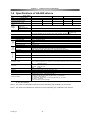
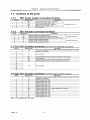
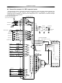
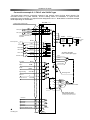
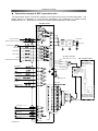
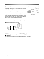
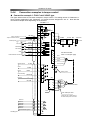
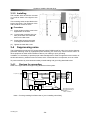
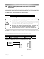
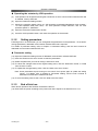
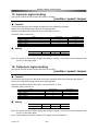
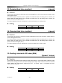
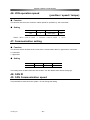
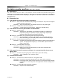
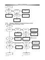
Chapter 2 I/O ports
2-2-4
Connection examples in the position control
◆ Connection example 1-1: FHA-C mini 24VAC type
The figure below shows a connection example in the position control for [open collector] signals. The
command format is “2 pulse method,” and the setting values of “Parameter 11: Input function
assignment” and “Parameter 12: Output function assignment” are “0.” Note that the connection example
varies depending on the actuator.
+5V power supply & external resistance
HA-680-*-***
R1, R2 are user’s responsibility.
Signal current should be 16mA.
CN2
+5V
FWD pulse
2.2k
+24V 18
FWD+
14
FWD-
15
REV+
16
REV-
17
REV pulse
2.2k
235
TB2
235
CP+
CP-
COM(0V)
MP+
External power
DC24V
0V
Servo-ON
FWD inhibit
REV inhibit
Alarm clear
IN-COM
12
S-ON
7
FWD-IH
8
REV-IH
9
CP
Line filter
AC/DC
Power
supply
MP-
3.3k
DC24V
NFB Transformer
L/F
3.3k
3.3k
TB1
3.3k
ALM-CLR
10
DEV-CLR
11
VM
R
3.3k
Deviation clear
IN-POS
1
AC Servo Actuator
FHA-**Cmini (24V type)
GND
U
Red
V
White
W
Black
M
Green/yellow
ALARM
2
Ready
READY
3
Speed limiting
SPD-LMT-M
4
Phase-Z
Z
5
Output common
OUT-COM
6
Ground always
CN1
+5V
0V
SD
SD
Shell
11
Red
88
Black
Yellow
55
E
Incremental encoder
Blue
7
Shield
Use shield pair cable
Clamp the end of shield surely to
the cable-clamp of the connector.
Phase-A+
21
Phase-APhase-B+
22
23
Phase-BPhase-Z+
24
25
Phase-Z-
26
13
Encoder Monitor ground
26LS31
- 26 -
HA-680_V04
Shell
Shield
AC
Power input