1
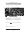
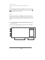
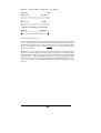
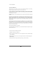
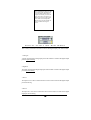
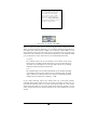
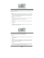
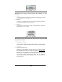
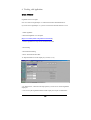
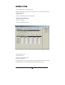
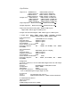
CONTENTS 1. OVERVIEW------------------------------------------------------------- 3 FEATURES---------------------------------------------------------------- 3 2. HARDWARE INSTALLATION-----------------------------------------------WHAT'S IN THE BOX------------------------------------------------------MINIMUM SYSTEM REQUIREMENTS--------------------------------------------RECOMMENDED SYSTEM REQUIREMENTS----------------------------------------PRECAUTIONS------------------------------------------------------------PCI CARD INSTALLATION--------------------------------------------------OPTIONAL MIDITERMINAL 2120---------------------------------------------- 5 5 5 5 6 7 8 3. EXTERNAL CONNECTIONS------------------------------------------------- 9 BASIC CONNECTIONS------------------------------------------------------- 9 CABLES & ADAPTERS-------------------------------------------------------10 2-PIN HEADER LAYOUT-----------------------------------------------------12 4. DRIVER INSTALLATION--------------------------------------------------15 WINDOWS 2000------------------------------------------------------------16 WINDOWS 88SE------------------------------------------------------------19 5. WT2496 CONTROL PANEL REFERENCE---------------------------------------22 PULL-DOWN MENU BAR------------------------------------------------------22 INPUT/OUTPUT REFERENCE LEVELS-------------------------------------------23 ANALOG OUTPUT MIX MONITORING--------------------------------------------25 DIGITAL OUTPUT MIX MONITORING-------------------------------------------26 OUTPUT MIX MODE---------------------------------------------------------27 CLOCK SOURCE------------------------------------------------------------27 DIGITAL INPUT-----------------------------------------------------------28 SB-LINK OUT-------------------------------------------------------------28 IEC 958 TYPE------------------------------------------------------------29 SAMPLING RATE-----------------------------------------------------------30 REALTIME SAMPLE RATE CONVERTER------------------------------------------30 6. WORKING WITH APPLICATIONS--------------------------------------------31 GIGA STUDIO-------------------------------------------------------------31 CAKEWALK SONAR----------------------------------------------------------33 CUBASE------------------------------------------------------------------36 REASON------------------------------------------------------------------37 LOGIC-------------------------------------------------------------------38 7. SPECIFICATIONS-------------------------------------------------------39 Allfeaturesandspecificationssubjecttochangewithoutnotice. 2 1.Overview Thank you for choosing the Waveterminal 2496. You have made the best choice in audio interface cards, as you will find out shortly. The Waveterminal 2496 (WT2496) is a professional 24-bit PCI digital audio card for the IBM PC and compatibles. The WT2496 can be used with your digital audio recording software to record and/or playback 2 analog and/or 2 digital audio sources simultaneously (full duplex) with exceptional audio quality. On the surface, the WT2496 may appear to be a simple 24-bit/96kHz sample rate upgrade of the original Waveterminal. However, there are major internal modifications and a multitude of new features that are unique to the WT2496. Through laborious research and development, we believe we have created the most reliable and versatile 24-bit 96kHz audio interface currently available anywhere in the world. Furthermore, inclusion of ASIO 2.0, GSI/F (GigaStudio), and WDM drivers allow the WT2496 to interface seamlessly with popular audio software. Best of all, take a listen and you will immediately notice the difference in the sound quality. After all that’s what it boils down to, isn’t it? Digital or analog, not all audio interface cards are made the same. If you are a professional or in need of a professional audio interface, you have made a sound investment in the Waveterminal 2496. FEATURES 24-bit/96kHz Sample Rate Analog-to-Digital and Digital-to-Analog Converters. Highest quality AD/DA converters in the WT2496 provide unmatched sound quality with exceptionally low noise. 2-In/2-Out Balanced or Unbalanced Analog Audio Inputs and Outputs. The WT2496 provides 1/4” TRS phone jacks for use with either professional +4dBu nominal level audio equipment or –10dBV nominal level consumer audio equipment. In either case, you can use unbalanced connectors as well. For the cleanest possible audio signal paths, you’ll never need to adjust levels. Unlike some audio cards that deliberately boost their output levels to give you a false sense of audio quality, the WT2496 gives you a true indication of your levels. What you hear is what you get. Nothing’s added or taken away unless you intend to do so. If you need to adjust levels, digital level adjustment is provided for analog inputs and outputs. 4 Channel Recording and Playback You can record analog and digital sources simultaneously and play them back simultaneously as well. 24-bit 96kHz S/PDIF Coaxial Digital In & Out Unlike some audio cards that claim 24-bit 96kHz capability, the WT2496 offers a true 24-bit 96kHz S/PDIF digital input and output. There’s no additional conversion process for a signal already recorded in a 24-bit 96kHz format. 3 32-bit Internal Resolution With ASIO 2.0, GSI/F, and WDM driver-supported software, you can transfer digital audio data at a maximum 32-bit internal resolution. It allows for a much greater dynamic range when you are working with digital audio. IEC958 Type I/II Selector With the recent adaptation of IEC958 as the standard in professional digital audio, the WT2496 is currently one of the few audio interfaces that supports the IEC958 Type I AES/EBU format. CD-ROM Digital Audio Input Port The WT2496 provides an on-board 2-pin port that can be used to connect directly with CDROMs that have digital audio output pins. This allows you to transfer CD digital audio directly to your PC with ease, and you can play back your CD audio with the WT2496’s 24bit 96kHz DA converter. SoundBlaster Live Value ! Digital Connector (SB-Link) SoundBlaster is probably the most widely used Windows compatible soundcard standard. If you own a SoundBlaster Live Value! Soundcard, you now can send its outputs directly to the WT2496 and use the higher quality AD/DA converters on the WT2496. In addition, the WT2496 can convert the fixed 48kHz sample rate of the SoundBlaster Live Value! to a 44.1kHz CD-audio sample rate. Internal Word Clock Connector If you are working in professional digital audio, Word Clock is not just an additional feature, but a necessity. The WT2496 contains an on-board Word Clock input and output port which you can use to synchronize all your digital audio equipment. It provides both the normal fs, as well as the Super Clock 256fs format. Multiple Sample Rate Support The WT2496 supports all denominations of 44.1kHz or 48kHz standard sample rates from 8kHz to 96kHz (8kHz, 11.025kHz, 12kHz, 16kHz, 22.05kHz, 24kHz, 32kHz, 44.1kHz, 48kHz, 64kHz, 88.2kHz, and 96kHz). The WT2496 can be used in a variety of applications ranging from multimedia and audio production to DVD production. Real-time Hardware Sample Rate Conversion Regardless of the type of sample rates, the WT2496 automatically converts the incoming digital audio signal to the sample rate of your choice in real-time. Uses 32 Bit PCI Slot for PCI Bus-mastering Support Already appreciated by many users of the Waveterminal for its PCI bus mastering quality, the WT2496 uses as little as only 4% of system resources. Other audio/sound cards can use up to more than 30% of system resources, which ties up the computer’s CPU. The WT2496 operates independently from the CPU, which allows you to use more software plug-in effects without placing a heavy burden on the CPU. 4 2. Hardware Installation To install all components of the WT2496 properly, you should install the PCI card first and make all audio and header pin connections before you install the WT2496 Driver and the Control Panel. If you follow the instructions in this section in the sequence that it is written, you will have properly installed all components. After the WT2496 has been installed, you may need to reinstall a part or all of your digital audio recording applications. WHAT’S IN THE BOX The WT2496 is shipped with the following contents: 1. WT2496 PCI card 2. Driver CD 3. This manual 4. 2-pin header connector cable MINIMUM SYSTEM REQUIREMENTS Because the WT2496’s dependence on the CPU is very low, you can use the WT2496 on virtually any Pentium-based system. Your first consideration should be the system requirements of the software you will be using. If your digital audio application's system requirements are met, then the WT2496 will run without any problems. 1. Intel Pentium II CPU 2. 64MB of RAM 3. One available PCI slot 4. Microsoft Windows 98 SE/ME/2000/XP Operating System 5. Ultra DMA 33 hard disk drives RECOMMENDED SYSTEM REQUIREMENTS Your digital audio application’s system requirements should be checked first, as the WT2496’s dependence on the system resources is very low. As a general rule, however, digital audio applications perform better with faster clock speed and more RAM. 1. Intel Pentium III 600MHz CPU or higher 2. More than 256MB of Ram 3. One available PCI Slot 5 4. Microsoft Windows 98SE/ME/2000/XP Operating System 5. UDMA 66/100 7200 rpm hard disk drive A B O U T T H E M I D I T E R M I N A L 2 1 2 0 ( O P T I O N A L ) The MIDI Terminal 2120 is a 2 In, 2 Out MIDI Interface from ESI. The MIDI Terminal 2120 is ONLY designed to be used with the ESI Waveterminal 2496. You can use it easily with a simple installation. The MIDI Terminal 2120 is an easy installation device and does not require any power supply, IRQ setting, or driver to install. The MIDITerminal 2120 driver is already included in the driver of the WT2496. Therefore, by the installation of the driver for the Waveterminal 2496, you can use the MIDI Terminal 2120 right away. The MIDI Terminal 2120 can be used under Windows 98SE/ME/2000 with the Waveterminal 2496. Particularly, it will work under Windows 2000 to provide the most stable MIDI work Environment. Warning! The components in your PC and on the WT2496 board are sensitive to electrostatic discharge. Follow these precautions to avoid damage caused by static electricity. PRECAUTIONS 1. Leave the WT2496 board in its anti-static wrapping until you are properly grounded. 2. Turn off your computer’s main power switch, and unplug the power cord. 3. Remove the cover to expose the internal parts of your computer. You should follow your computer’s manual on how you can do this safely. 4. To be grounded, touch the PC’s metal chassis with both hands. 5. Only handle the WT2496 by its edges and metal bracket. Do not touch the components of the board even after you have been grounded. To avoid further static electricity hazards, you should avoid wearing static clothing and follow the above procedures every time you have to install or de-install the WT2496 board. 6 W T 2 4 9 6 C A R D I N S T A L L A T I O N Waveterminal 2496 Before you begin using the WT2496 card, it is very important that you disable Advanced Power Management. If you do not disable this option, you may experience dropouts or clicks when recording and playing with the WT2496 card. To install the WT2496 card in your computer: 1. Turn off your computer. Leave it plugged in so that is grounded. 2. Open the computer case. Remove the screw and the rear slot cover of an available PCI expansion slot in your computer. 3. Discharge any static electricity that may be on your clothes or body by touching a grounded metal surface such as the power supply case inside the computer. 4. Remove the card from its anti-static bag. 5. Push the card firmly but gently into the PCI slot until the card’s connector clicks into place. Make sure the audio connectors at the rear of the card go through the rear slot of the computer. 6. Attach the rear bracket of the card to the computer, using the screw from the rear slot cover. 7 Optional MIDI Terminal 2120 MIDI Interface To install the MIDI Terminal 2120 card in your computer: 1. Turn off the computer power and remove the cover. 2. You require one empty slot close to the Waveterminal 2496. 3. Connect the MIDI Terminal 2120 connection cable to the WT2496 connector. The cable can be connected only one way. 4. Place the MIDI Terminal 2120 into the empty slot. Be careful not to touch other cards to avoid any damage to the cards. 5. Check to see if the MIDI Terminal 2120 is in place firmly. 6. Locate the MIDI cable connector at the back of the computer. 7. Connect all 4 MIDI connector plugs that are provided. 8. Connect the MIDI cables to the MIDI plugs (MIDI cables are not included in the package). Parts of this manual are continually being updated. Please read the README.TXT file included in the driver diskette for the latest update, information and be sure to check our web site http://www.egosys.net occasionally for the most recent update information. 8 3.ExternalConnections The WT2496 has many features that can enhance your audio production environment. If you are serious about your digital audio, you may want to take time to read through this section carefully. While you may not need all of these features, and simply opt to plug in the cables to get started right away, you should at least be aware of the WT2496’s capabilities – in case you need them later on. BASIC CONNECTIONS Shown below is just one of many possible connection schemes for the WT2496. In a typical audio production studio or workstation, where you have both digital and analog devices, this setup treats your PC as a stereo master recorder. In this case, monitoring of the WT2496 will be similar to “through-the-tape” monitoring, where you monitor your input and output sources from the tape recorder’s point. If you plan to use the WT2496 in a digital mastering environment, you may choose to connect the analog outputs of the WT2496 directly to your power amplifier’s inputs instead of sending it through the console/mixer. 9 CABLES & ADAPTERS To make use of the WT2496’s balanced analog inputs and outputs, you should have the appropriate XLR to 1/4” TRS (tip-ring-sleeve) cables. 1. Balanced Connections The wiring method for balanced connections with XLR connectors to balanced TRS (1/4" phone) connectors using a shielded twisted pair cable (2 wire + shield) are as follows: 2. Unbalanced Connections with a Twisted Pair Cable The wiring method for unbalanced connections with XLR connectors to phone connectors (tip and sleeve only) using a shielded twisted pair cable (2 wire + shield) is as follows: 10 The wiring method for unbalanced connections with XLR connectors to unbalanced RCA/Phono phone connectors using a coaxial cable (1 wire + shield) is as follows: The wiring method for unbalanced connections with XLR connectors to unbalanced 1/4” phone connectors (tip and sleeve only) using coaxial cable (1 wire + shield) is as follows: : The wiring method for unbalanced connections with XLR connectors to unbalanced RCA/Phono phone connectors using a shielded twisted pair cable (2 wire + shield) is as follows: 11 2-PIN HEADER LAYOUT The on-board header pins provide more I/O ports to make the WT2496 the centerpiece of your audio production. If you plan on using any of the header pins, you should make the connections before you install the WT2496 driver. Please read through this section carefully if you intend to use any of the functions described below. When you connect devices to the 2-pin header connectors on the Waveterminal 2496 card, remember that the left one is pin number 1. This one is for the signal and the right one is pin #2 for ground purposes. The 2-pin header connectors are in two colors. It doesn’t matter which color goes with which pin, but make sure to match the signal pin to the signal pin of the other device. 1. WCLK IN This is the word clock input header to connect a word clock output from another digital device to the WT2496. You can use this word clock to synchronize all your digital audio on the WT2496. To do so, select Word Clock as the Clock Source in the WT2496 Control Panel. 2. WCLK OUT This is the word clock output of the WT2496. The selection you make in the Clock Source of the WT2496 Control Panel is routed to this output. 12 3. SYNC IN/SYNC OUT These pins are used for synchronizing the WT 2496 with other ESI products. 4. S/B IN Connect a digital audio output header pin on the SoundBlaster Live Value soundcard to S/B IN to get the SoundBlaster’s digital audio output directly into the WT2496. Choose SB LINK IN as the Digital In selection in the WT2496 Control Panel to receive and monitor the SoundBlaster digital output signal on the WT2496. 5. S/B OUT Connect the digital audio input on the SoundBlaster Live Value soundcard to S/B OUT to send the WT2496’s digital output to the SoundBlaster directly. In the WT2496 Control Panel SB-LINK OUT, you can decide what you send to the SoundBlaster’s digital audio input – CDROM digital audio, coaxial digital audio input source, or the digital audio mix output of the WT2496. The SB Link feature was specifically designed for SoundBlaster Live Value users who can not use the digital bracket option. The Provided pin map on the SB card is only for the SB Live Value Cards. Directions for connecting the SoundBlaster Live Value to the Waveterminal 2496 12-pin Header Block on the Right Edge of SB Live Value J 10 1 3 5 7 9 11 13 2 4 6 8 10 12 SPDIF_EXT *WT2496’s number (1,2) Indicates signal (1) and ground(2). SBLiveValue WT2496 Front ch out. S/B_DIN 1 ----------------------------------------------------1 2 ----------------------------------------------------2 or Rear ch out S/B_DIN 12 -------------------------------------------------- 1 10 -------------------------------------------------- 2 *using the front channel is recommended. Digital In S/B_DOUT 6 --------------------------------------------------- 1 5 ---------------------------2 6. CD-ROM Digital Audio Input If your CD-ROM is equipped with a 2-pin digital audio output (usually named “D” for signal and “G” for ground), you can bypass all DAC circuitry of the CD-ROM and import the CD digital audio signal directly to the WT2496 via this connector. To use the CD-ROM’s digital audio as your digital input source, select CD-ROM as the Digital Input selection on the WT2496 Control Panel. When you connect CD-ROM to monitor an audio CD through the Waveterminal 2496, make sure to match the signal pin to the corresponding signal pin. For example, the left pin of the 2-pin header connector is a signal pin, so connect it to the letter “D” from the CD-ROM digital output port. Some CD-ROM models simply do not support the digital out port for CD audio. If you cannot hear any sound from the CD-Rom after making the proper settings, you may need to ask to the CD-ROM manufacturer if the Digital Output port is in fact activated. 14 4.DriverInstallation About the E-WDM Driver: WDM (Windows Driver Model) is the new driver model from Microsoft. It was initially designed to simplify and unify existing drivers for the Windows OS. Using this WDM, EGO SYS has succeeded in developing a one-driver model for MME, DirectSound, ASIO, GIGA WIRE and GSIF in multi-streaming /client mode under Windows 2000/ME/98SE environments. E-WDM technology is the true digital audio driver solution for future Windows Operating Systems. EGO SYS has concentrated energies on developing this new multi-purpose driver for new Windows Operating Systems, such as Windows ME, 2000, and even XP. Unlike non-WDM Windows 2000 compatible drivers, this newly-developed driver using E-WDM technology from EGO SYS will function as digital audio drivers like MME, DirectSound, ASIO, GIGA WIRE and GSIF. Until EGO SYS succeeded in developing the E-WDM driver, other so-claimed Windows 2000 compatible drivers were not the perfect solution for the new OS format. When a new OS is released, 3rd party developers have to develop a new driver following a new standard and format. However, no one ever succeeded in achieving new digital audio drivers for WDM, especially in multi-channel Mode. This makes the E-WDM driver very unique. As its name implies, the E-WDM driver provides enhanced functions compared to regular WDM compatible drivers. - One driver solution for multiple driver formats - Compatible with Nemesys’s GSIF driver - Multiple Applications (different drivers) can be assigned to the same (or different) output ports – Multi-client - Multiple Applications (same driver) can be assigned to the same (or different) output ports – Multi-Streaming - Enhanced performance for digital audio data processing –yields lower latency. 15 1. Windows 2000 1. Turn your computer’s main power on. Windows will automatically detect that a new card has been installed and “Welcome to the found New Hardware Wizard” will appear. 2. When the Wizard prompts you to “Search for a suitable driver for your device (Recommended),” select it and click “Next.” 16 3. Insert the WT2496 E-WDM Driver floppy disk into your computer’s floppy disk drive A. Or insert the WT2496 E-WDM Driver CD into your computer’s CDROM 4. Follow the on-screen instructions to finish the installation of the Waveterminal 2496 driver. When the Wizard prompts you to restart your computer, select YES and remove the Waveterminal 2496 Driver Diskette from the floppy disk drive. 17 5. After rebooting the computer, your Waveterminal 2496 Audio Card is now ready to use. 18 2. Windows 98SE 1.Turn your computer’s main power on. Windows will automatically detect that a new card has been installed and “Add New Hardware Wizard” will appear. 2.When the Wizard prompts you to “Search for the best driver for your device (Recommended),” select it and click “Next.” 19 5. Insert the Waveterminal 2496 Driver floppy disk into your computer’s floppy disk drive A. Or insert the Waveterminal 2496 Driver CD into your computer’s CD-ROM. 6. Follow the on-screen instructions to finish the installation of the Waveterminal 2496 driver. When the Wizard prompts you to restart your computer, select YES and remove the Waveterminal 2496 Driver floppy disk from the disk drive. 20 6. After rebooting the computer, your Waveterminal 2496 Card is now ready to use. Please read the README.TXT file included in the driver diskette for the latest driver update information, and be sure to check our web site http://www.egosys.net occasionally for the most recent driver update information 21 5. WT2496 ControlPanel Reference If you have properly installed both the hardware and the software driver for the WT2496, your system will display a ‘WT’ icon on your desktop system menu bar. Click it once and it will display the Waveterminal 2496 Control Panel as below. While reading through this section, it may help to actually sit down in front of your PC and experiment. In some shipping versions of the Waveterminal2496, the screen may not look exactly as below. Please check our web site (http://www.egosys.net) for the most recent software updates. PULL-DOWN FILE - -Exit 22 MENU BAR This will terminate the Waveterminal 2496 Control Panel Applet but it will not actually shut down the Control Panel. You can launch the Control Panel again by clicking on the Waveterminal 2496 icon in your system tray. CONFIG -Mouse Wheel The Config–Mouse Wheel will control the mouse wheel adjustment. When you use the mouse wheel to adjust the volume level, the adjustment step is set to 0.5dB. You can configure the adjustment steps to your preference. Step 1 : When you move the mouse wheel one step, the fader will move by 0.5dB. Step 2 : When you move the mouse wheel one step, the fader will move by 1dB. Step 4 : When you move the mouse wheel one step, the fader will move by 2dB. Step 8 : When you move the mouse wheel one step, the fader will move by 4dB. -Latency This will determine the latency of the Waveterminal 2496. Before running other applications, you should decide the latency, and then launch the applications. * With lower latency, a quicker response time is achieved. * With higher latency (a larger sample size), more stability is acquired. You should check your computer system environment and choose the proper latency. * We recommend you to set the latency in the Control Panel: 64 or 128 samples - for 1 track of real-time keyboard inputs. 256 or 512 samples - for recording or mixdown projects. -Factory Default This returns all Waveterminal 2496 configurations to their default settings. -Always On Top This will set the Waveterminal 2496 Control Panel to always display over the active windows. . 23 INPUT/OUTPUT REFERENCE LEVELS WT2496 connectors can accept normal unbalanced 1/4” phone jacks as well, but you must select UNBAL for proper use. Generally speaking, balanced line normally refers to the +4dBu nominal level, while the unbalanced line normally refers to the –10dBV nominal level. Although rare, there can be an unbalanced +4dBu line or a balanced –10dBV line. 1. Level Faders Click and drag to change the input and output levels. For best results, you should select either +4dBu or –10dBV according to your system configurations. Check the manuals of the audio equipment you want to connect to the WT2496’s inputs. It should be either a +4dBu or –10dBV device. The numbers on the bottom show the relative levels in dB. When you select balanced operation, the preset levels are 0dB for both inputs and outputs. When you select unbalanced operation, the level will show 6 for inputs and 0 for outputs. 2. +4dBu Sets the nominal input and output levels to +4dBu for professional audio applications. 24 3. –10dBV Sets the nominal input and output levels to –10dBV for consumer audio applications. 4. BAL Select if you are using balanced lines. Balanced lines usually have 3 connectors, such as XLR connectors or 1/4” TRS (tip-ring-sleeve) phone jacks. 5. UNBAL Select if you are using unbalanced lines. Unbalanced lines usually have only 2 connectors, such as RCA type jacks and the normal 1/4” phone jacks. 6. Gang Mode This links the L-R faders for stereo operation. Un-select the Gang Mode if you need to control the left and right levels independently. ANALOG OUTPUT MIX MONITORING This is where you select the source that is routed to the Analog Output jacks of the WT2496. You can select just one or all four simultaneously. 1. Analog In A signal connected to the Analog Input ports of the WT2496 is routed to the Analog Output ports for input monitoring. 2. Digital In A signal connected to the Digital Input port of the WT2496 is routed to the Analog Output ports for input monitoring. 3. Wave 1 The output of a wave device routed to the Waveterminal 2496 is routed to the Analog Output ports for monitoring. 4. Wave 2 The output of a wave device routed to the Waveterminal 2496(D) is routed to the Analog Output ports for monitoring. 25 Just remember that when you add two audio signals together, there is about 3dB overall increase in signal level. When you select all four, there can be as much as 12 dB increase in the overall output level. Refer to the Output Mix Mode section for more details on how to handle mixed signal levels. DIGITAL OUTPUT MIX MONITORING This is where you select the source that is routed to the Digital Output jacks of the WT2496. 1. Analog In A signal connected to the Analog Input ports of the WT2496 is routed to the Digital Output ports for input monitoring. 2. Digital In The signal connected to the Digital Input port of the WT2496 is routed to the Digital Output port for input monitoring. 3. Wave 1 The output of a wave device routed to the Waveterminal 2496 is routed to the Digital Output port for monitoring. 4. Wave 2 The output of a wave device routed to the Waveterminal 2496(D) is routed to the Digital Output port for monitoring. 26 Just remember that when you add two audio signals together, there is an overall increase in the signal level. When you select all four, there can be as much as 12 dB increase in overall output level. Refer to the Output Mix Mode section for more details on how to handle mixed signal levels. OUTPUT MIX MODE When more than one output source is selected to be played back simultaneously in the Analog or Digital Output Mix Monitoring, you are actually combining the data of two or more digital audio signals together, resulting in an overall gain of about 6dB/bit for each signal combined. This can cause the output circuit to overload and create a noticeable click or distortion as the combined level can exceed the 0 dB peak level. The output Mix Mode gives you the choice as to how such excessive levels are handled by the WT2496. 1. Dynamic The combined signal levels are not adjusted by the WT2946. In this mode clipping signals are audible, but left untouched. If you want to adjust the levels, you can do so by adjusting the levels from the audio software or by manually reducing the output level faders of the WT2496. 2. Soft The combined signal levels are reduced automatically by the WT2496, depending on the number of signal sources combined. For two combined signals, the output signal is reduced by –6 dB. When three or four signals are combined (played back simultaneously), the output level is reduced by –12 dB. If your output monitoring sources don’t contain peak level (0 dB peak) programs, combining them probably would not cause any clipping or distortion. In such cases, you may opt for the Dynamic mode, as it will allow you to add the signals for a much “hotter” output. On the other hand, if your sources already contain peak level programs, you may need to select the Soft mode or manually adjust the levels of each output source you have selected. 27 CLOCK SOURCE Clock source is the time reference that determines precisely where each digital audio sample begins and ends. When you set a wrong clock source you will notice either drop-outs or you will not get any audio output. 1. Internal Selects the WT2496’s on-board clock source as the reference. This is the default mode for recording analog audio through the WT2496. Use this mode if you are running two or more digital audio or MIDI software applications simultaneously without any external synchronization. 2. Digital In Selects the digital audio input’s data as the clock source. Use this mode if you are recording digital audio through the WT2496’s digital input. 4. Word Clock Selects the clock source connected to the WT2496’s on-board header pin as the reference clock. 5. WT-Link Selects the clock source of the other EGO SYS products connected to the SYNC IN header pin as the reference clock. DIGITAL INPUT Select the input connector type for your digital audio input. 1. Coaxial In Selects the digital input port (RCA type S/PDIF format) on the WT2496 as the digital input source. 2. CD-ROM Selects the CD In 2-pin header connector on the WT2496 as the digital input source. You must have the CD-ROM digital audio output connected to the 2-pin header connector on the WT2496 card. 3. SB-Link In Selects the SB/D-In 2-pin header on the WT2496’s PCI board as the digital input source. You must have the SoundBlaster Live Value card’s digital audio output connected to the 2-pin header connector on the WT2496 card. 28 SB-LINK OUT This determines what’s being sent from the WT2496 to the SoundBlaster Live Value soundcard. 1. Coaxial In A source connected to the WT2496’s Coaxial (RCA jack) digital input is routed to the SoundBlaster Live Value soundcard. 2. CD-ROM A signal from a CD-ROM connected to the WT2496’s internal 2-pin header is routed to the SoundBlaster Live Value soundcard. 3. Digital Out The output signal on the WT2496’s Coaxial (RCA) digital output is routed to the SoundBlaster Live Value soundcard. IEC 958 TYPE The IEC 958 Type selector determines the type of data format to be used on the digital output jack of the WT2496. 1. Consumer (IEC 958 Type II) Generally known as S/PDIF (Sony Phillips Digital Interface), select this mode if you are sending the digital audio output from the WT2496 to an S/PDIF equipped audio device. 2. Professional (IEC 958 Type I) Generally known as AES/EBU, select this mode if you are sending the digital audio output from the WT2496 to an AES/EBU audio device. Important Notice: Since the adaptation of IEC958 no longer distinguishes between S/PDIF and AES/EBU, some older AES/EBU audio equipment require a higher signal level than the WT2496’s digital output levels (which conform to IEC 958 standards). If you experience problems transferring digital audio from the WT2496 to AES/EBU equipment, you may need a signal converter such as EGO SYS’s Dr. D to boost the level. 29 SAMPLING RATE Sample rate determines the samples per second that is used to convert analog audio to digital audio. As most of you may know, sample rate for CD-DA is 44.1kHz and professional digital audio masters are usually recorded at 48kHz sample rate. WT2496(and all other audio cards with 96kHz sample rate capability for the matter), maybe used to sample analog audio at 96kHz, but at some point in time it must be convicted down to 44.1kHz for it to be used in a viable consumer format, such as CD-DA. It’s important to keep in mind that 24bit 96kHz sample rate offers you the highest digital audio quality currently available – so long as it is kept in that format. Once you convert(dither) the data down to a lower sample rate format, you will experience some losses in dynamic range and/or frequency response. However, analog audio recorded with higher sample rate and bit resolution will sound cleaner and retain more accurate frequency response when they are dithered down to lower bit rate or converted to lower sample rate. When choosing an unconventional sample rate, make sure your digital audio software can support that format. For example, if you select 96kHz on WT2496 control panel, yet your software can only support 48kHz, it will either play the sound at half the normal speed or not playback at all. In either case, it just ends up taking up more hard disk space without any benefit to sound quality. REALTIME SAMPLE RATE CONVERTER The WT2496 can function as a real-time sample rate converter. This is the WT2496’s unique function that you cannot find on any other digital audio interface. You can change the incoming digital signal to a different sample rate by choosing Internal word clock, click the ON button to enable the function and select a desired sample rate. The maximum conversion ratio is 3:1, so if your input signal’s sample rate is 32kHz, you can convert it down to 11kHz (32/3) or convert it up to 96kHz (32 x 3). Real Time Sample Rate Converting functions only for an incoming digital signal. Connect the digital source to the Coaxial Input port and turn on the SRC. Choose the desired sampling rate. Now the sampling rate of the signal you receive from the digital output port is converted. However, you cannot change the sampling rate of .wav files that play back through the application. If you try to convert it, it only sounds like sampling up (faster speed than normal) or sampling down (slower than normal). 30 6. Working withApplications GIGA STUDIO GigaStudio 160 V.2.2 or higher Note: You cannot use GigaSampler v1.6 with the Waveterminal 2496 EWDM driver. If you want to use GigaSampler v1.6, you have to use the Waveterminal 2496 driver V.2.4. 1. Install GigaStudio. 2. Download GigaStudio v2.2 and update. [http://www.nemesysmusic.com/products/versions.html] 3. Launch GigaStudio and set up the Waveterminal 2496 GSIF. -Choose Setting -Choose Hardware/Routing -Choose ‘Waveterminal 2496 GSIF’ -In ‘Outputs Enabled’ choose the output port you want ( 1,2 3,4 ). 4. In ‘Midi In Ports,’ Choose the midi input port that you want to use with the GigaStudio output port. 5. You can set up the GigaStudio Instrument audio output port in ‘Input’ of ‘DSP Station.’ 31 * Caution 1 You can use the multi client function in GigaStudio. Using the EWDM drivers with GigaStudio v2.2 can support the use of GigaStudio with another audio application without choosing a different output port. You can use the same output port for two different audio applications. For example, the outputs of Cakewalk and GigaStudio can both go to the Waveterminal 2496 Outputs. * Caution 2 In the above case you have to be cautious with the output levels of each audio application. Two different outputs routed to the same output may cause noise due to clipping. You should lower the output level in comparison to using only one audio application at a time. * Caution 3 GigaStudio functions more properly when working at a low latency. Go to the Config Menu in the WT2496 Control Panel. Set the latency to 64 or 128 samples. Higher latency has the possibility of generating noise. . 32 CAKEWALK SONAR 1. Select 44.kHz from the "Control Desk" panel. 2. When running Sonar for the first time, it may display an error message if the bit rate was selected as 16 by default. Simply ignore it. 3. Go to the Option Menu and open "Audio Dialog." 4. Select the "Driver Profiles" tab. - Turn off the Access driver in mono. - Stream -> 16-bit data Select "32-bit PCM left-justified." 5. Select the "Drivers" tab. - Select In/Out Drivers. 6. Select the "Input Monitoring" tab. - Select the required driver. We recommend you to use input monitoring of the Waveterminal 2496 instead of input monitoring in Sonar. It’s more accurate than using input monitoring of Sonar. 33 7. Select the "General" tab. - Choose "Audio Driver Bit Depth = 24." - Sample rate = 44100 NOTE: If you want to choose another sample rate, the Control Desk should be selected first, otherwise an error message will appear. 8. Press the "Wave Profile" button. 9. Exit Sonar to store your new configuration. 10. Start Sonar again. 11. To perform Live Monitoring at 1.5 ms with Sonar, Exit Sonar to change the latency. Set "Latency" = 64 samples from the ‘Control Desk,’ then start Sonar again. Set "Buffers in playback" = 2. Set "Buffer size" slider to the left end (fast). Press "Wave Profiler." 12. Please don't select “Share Drivers With Other Programs." 34 35 CUBASE ASIO Setup Cubase VST 32 5.0 Goto Menu ‘Options’ => ‘Audio Setup’ => ‘System’ – ‘Audio System Setup’ ‘Audio I/O’->’ASIO Device’->choose ‘ASIO 2.0-Wami Rack 24’ You have to set up the latency of the ASIO driver from the Waveterminal 2496 ‘Control Desk’ instead of the Cubase Audio system setup. This is different with the v.2.4 drivers. 36 REASON 1. Select 44.1 from the "Control Desk" panel. 2. Start Reason. 3. Go to Edit -> Preferences. 4. Select "Page": Audio. 5. Select the ASIO driver from "Audio Card Driver." 6. If you see the error message - "ASIO is in use..." then please change the sample rate in the Control Desk to either 44.1kHz or 48kHz. Then try again from step 4. 37 LOGIC 1. Select 44.1 from the "Control Desk" panel. 2. Start Logic. 3. Go to "Audio"->"Audio Hardware & drivers." 4. Select the "Audio Driver 2" tab. 5. Check the "ASIO" box and select the ASIO 2.0 Waveterminal 2496 Driver from "Driver." 6. Check the "Software monitoring" box. 7. Close the Audio Window. 8. Go to "Options"->'Settings"->"Synchronization Settings." 9. Select the "MIDI" tab. 10. Select a port from "Transmit MIDI Clock." To avoid "Audio, Midi sync error..." or "CPU overload error...", please do not check "All ports" from "Transmit MIDI Clock." 11. Please make inactive any software synth that is not required for your current project. Otherwise, it will result in a heavy CPU overload by executing the same audio dma engine. This can also cause ASIO to generate clicks and pops. 38 7.Specifications 1. Input Level +4dBuBalanced: +4dBuNominal,+24du max. +4dBu Unbalanced: +4dBu Nominal, +18dBu max. -10dBV Balanced: -10dBV Nominal, +9.5dBV max. -10dBV Unbalanced: -10dBV Nominal, +3.5dBV max. 2. Output Level +4dBu Balanced: +4dBu Nominal, +22.5dBu max. +4dBu Unbalanced: +4dBu Nominal, +16.5dBu max. -10dBV Balanced: -10dBV Nominal, +8.5dBV max. -10dBV Unbalanced: -10dBV Nominal, +2.5dBV max. 3. Input Impedance: Balanced mode 40KΩ, Unbalanced mode 20KΩ 4. Output Impedance: Balanced mode 200Ω, Unbalanced mode 100Ω 5. Input Gain/Attenuation Analog: 0dB ~ 18dB in 0.5dB step sizes Digital 72dB ~ 0dB, in approx. 0.5dB step sizes 6. Output Gain/Attenuation Digital: 72dB ~ 0dB, in approx. 0.5dB step sizes 7. Sample Rates: 8KHz, 16KHz, 32KHz, 64KHz, 11.025KHz, 22.05KHz, 44.1KHz, 88.2KHz,12KHz, 24KHz, 48KHz, 96KHz 8. A/D Specifications: 1) Type 24-Bit 96kHz, 64x Over sampling 2) Dynamic Range 100dB A-weighted 3) Signal-to-Noise Ratio 100dB A-weighted 4) S/(N+D) Ratio 90dB 5) Inter channel Gain Mismatch 0.2dB 6) Frequency Response 1Hz ~ 20KHz (FS=44.1KHz) 1Hz~ 40KHz (FS=96KHz) 9. D/A Specifications: 1) Type: 24Bit 96kHz, 128x Over sampling 2) Dynamic Range: 110dB A-weighted 3) Signal-to-Noise Ratio: 110dB A-weighted 4) S/(N+D) Ratio: 94dB 5) Inter channel Gain Mismatch: 0.2dB 6) Frequency Response: 1Hz ~ 20KHz (FS=44.1KHz) 1Hz ~ 40KHz (FS=96KHz) 10. Digital I/O 1) Type RCA connector, 1 in/1 out 24-Bit 96kHz Digital Audio I/O with Sample Rate Converter 2) Format: IEC60958,AES 3, S/PDIF,EIAJ CP1201 3) Sample Rate: 8KHz ~ 96KHz 4) Resolution: 24 Bits 5) Sample Rate Converter: 128dB Dynamic Range 1:3 & 3:1 Maximum input to output sample rate ratio 11. Analog I/O 1) Type: 2) Format: 1/4” TRS Phone jack, 2 in/2 out +4dBu nominal, balanced or –10dBV nominal, unbalanced 12. Additional Header Pin I/O 1) Word clock in/out 2) Sync in/out 3) CD-ROM digital audio in/out (S/PDIF) 39