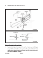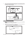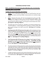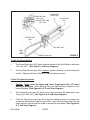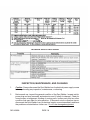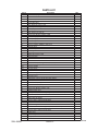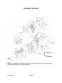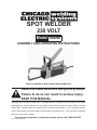
1
spot welder
230 volt
Model 45690
assembly and Operating Instructions
Visit our website at: http://www.harborfreight.com
Read this material before using this product.
Failure to do so can result in serious injury.
Save this manual.
Copyright© 2001 by Harbor Freight Tools®. All rights reserved. No portion of this manual or any artwork
contained herein may be reproduced in any shape or form without the express written consent of Harbor
Freight Tools. Diagrams within this manual may not be drawn proportionally. Due to continuing improvements, actual product may differ slightly from the product described herein. Tools required for assembly
and service may not be included.
For technical questions or replacement parts, please call 1-800-444-3353.
Revised Manual 02b, 09l
SPECIFICATIONS TABLE
ITEM
DESCRIPTION
Electrical Input Requirements
230 Volt
Rated Output
1.5 KVA @ 50% Duty Cycle
Output Amps
5,500 +/- 10%
Material Capacity
1/8” Thick, Mild Steet
Tong Length
6”
Overall Dimensions
13” x 6” x 4.5”
Net Weight
23.5 Lbs.
SAVE THIS MANUAL
You will need this manual for the safety warnings and precautions, assembly,
operating, inspection, maintenance, and cleaning procedures, parts list and assembly
diagram. Keep your invoice with this manual. Write the invoice number on the inside
of the front cover. Keep this manual and invoice in a safe and dry place for future
reference.
GENERAL SAFETY WARNINGS AND PRECAUTIONS
1.
KEEP WORK AREA CLEAN AND DRY. Cluttered, damp or wet work areas invite
injuries.
2.
KEEP CHILDREN AWAY FROM WORK AREA. Do not allow children to handle this
product.
3.
STORE IDLE EQUIPMENT. When not in use, tools and equipment should be stored
in a dry location to inhibit rust. Always lock up tools and equipment and keep out of
reach of children.
4.
DO NOT USE THIS PRODUCT IF UNDER THE INFLUENCE OF ALCOHOL OR
DRUGS. Read warning labels on prescriptions to determine if your judgment or
reflexes are impaired while taking drugs. If there is any doubt, do not attempt to use
this product.
5.
USE EYE, HEARING, BREATHING, AND HAND PROTECTION. Wear an ANSI
approved welding helmet/goggles with shaded lens, hearing protectors, breathing
respirator, and welding gloves when using this product. ANSI approved welding
helmet/goggles with shaded lens, hearing protectors, breathing respirators,and
welding gloves are available from Harbor Freight Tools.
6.
DRESS SAFELY. Sparks and hot metal can injure. Always wear body protection.
Non-skid footwear or safety shoes should be used when working with this product.
Do not wear loose clothing or jewelry as they can become caught in moving parts.
Wear a protective hair covering to prevent long hair from becoming caught in moving
parts. If wearing a long-sleeve shirt, roll sleeves up above elbows.
7.
INDUSTRIAL APPLICATIONS MUST FOLLOW OSHA REQUIREMENTS.
SKU 45690
PAGE 2
Rev 02b, 03h, 09l
8.
DO NOT OVERREACH. Keep proper footing and balance at all times to prevent
tripping, falling, back injury, etcetera.
9.
STAY ALERT. Watch what you are doing at all times. Use common sense. Do not
use this product when you are tired or distracted from the job at hand.
10. CHECK FOR DAMAGED PARTS. Before using this product, carefully check that it
will operate properly and perform its intended function. Check for damaged parts
and any other conditions that may affect the operation of this product. Replace or
repair damaged or worn parts immediately.
11. REPLACEMENT PARTS AND ACCESSORIES. When servicing, use only identical
replacement parts. Only use accessories intended for use with this product. Approved
accessories are available from Harbor Freight Tools.
12. MAINTAIN THIS PRODUCT WITH CARE. Keep this tool clean and dry.
13. MAINTENANCE: For your safety, service and maintenance should be performed
regularly by a qualified technician.
14. USE THE RIGHT PRODUCT FOR THE RIGHT JOB. There are certain applications for
which this product was designed. Do not use small equipment, tools or attachments
to do the work of larger industrial equipment, tools or attachments. Do not use this
product for a purpose for which it was not intended.
SPECIFIC PRODUCT WARNINGS AND PRECAUTIONS
1.
GROUND THIS PRODUCT. The required electrical Power Cord Plug for this
product is a grounded, 230 Volt, 3-Prong Plug (not included). It is recommended
that only a qualified technician connect a Power Cord Plug to the Power Cord. Never
remove the grounding prong or modify the Plug in any way. Do not use adapter
plugs with this product. When in use, make sure this product is always plugged into
a grounded, 230 Volt, 3-hole electrical receptacle with an appropriate breaker switch
inline.
2.
MAKE SURE THE CONTROL SWITCH (part #25) IS IN THE “OFF” POSITION
BEFORE PLUGGING IN THE POWER CORD. (See Figure D, and Assy.
Diagram.)
3.
DO NOT ABUSE THE POWER CORD. Do not use the Cord to pull the 3-Prong Plug
from a power outlet. Keep Cord away from heat, oil, sharp edges, and moving parts.
Replace damaged Cord immediately. Route the Power Cord safely. Protect it from
being damaged by other equipment in the shop. Do not route the Cord where it can
be walked on or tripped over.
MAINTAIN A SAFE WORK ENVIRONMENT. Do not use this product in or near
damp or wet areas. Do not expose this product to rain. Keep work area well lit.
Make sure there is adequate surrounding work space. Use this product in a well
ventilated area. (Read Material Safety Data Sheets/MSDS for metals, coatings, and
cleaners.) Do not operate this product in the presence of flammable liquids, gases,
or dust. To avoid accidental electric shock, do not let your body come in contact with
grounded surfaces such as pipes, radiators, ranges and refrigerators. Always keep
a fire extinguisher nearby.
Rev 02b
SKU 45690
PAGE 3
4.
5.
DO NOT FORCE THE EQUIPMENT. This Spot Welder will do the work better and
safer at the speed and capacity for which it was designed.
6.
AVOID UNINTENTIONAL STARTING. Make sure you are prepared to begin work
before turning the Control Switch (part #25) “ON”.
7.
Caution: Never touch the Upper and Lower Tongs (parts #46, #47) when welding a
workpiece. Allow the Tong Tips (part #48) and the workpiece to cool before handling.
(See Figures A, B, E, and Assy. Diagram.)
8.
MAKE SURE THE WORKPIECE IS SECURED AT ALL TIMES DURING OPERATION.
Use a vise, clamps, etcetera (not provided).
9.
OVERUSE CAN CAUSE OVERHEATING. After continuous use, allow the Spot
Welder adequate time to cool before the next use.
10. BEFORE TRYING NEW OR COMPLICATED TECHNIQUES, STUDY THE
PROCEDURE, AND PRACTICE WITH SCRAP METAL.
11. ALWAYS DISCONNECT THE SPOT WELDER FROM ITS ELECTRICAL
SUPPLY SOURCE BEFORE ASSEMLING, PERFORMING ANY SERVICES OR
MAINTENANCE always disconnect the electrical cord before leaving the work area,
moving the tool from one location to another, handing the tool to another person,
changing Tong Tips (part #48), cleaning the unit, etcetera.
12. WARNING: This product, when used for welding and similar applications, produces
chemicals known to the State of California to cause cancer and birth defects (or other
reproductive harm). (California Health & Safety Code 25249.5 et seq.)
13. Warning: Operation of equipment in close proximity to a heart pacemaker could
cause interference or failure of the pacemaker.
SKU 45690
PAGE 4
REV 04e
UNPACKING
When unpacking, check to make sure all parts shown on the Parts List (page 12) are included. If any parts are missing or broken, please call Harbor Freight Tools at the number
shown on the cover of this manual as soon as possible.
ASSEMBLY INSTRUCTIONS
NOTE: For additional references to the parts listed below, refer to the Assembly
Diagram on page 13 of this manual.
To Attach The Upper And Lower Tongs:
1.
Caution: Prior to attaching the Upper and Lower Tongs (parts #46, #47), make
sure the Spot Welder is disconnected from its electrical power source.
2.
NOTE: Make sure the Upper and Lower Tongs (parts #46, #47) are clean and not
corroded before installing. If necessary, clean the Tongs with steel wool.
3.
To attach the Lower Tong (part #47) to the Spot Welder, loosen the four Cap
Screws (part #3) located at the bottom/front of the tool. (See Figure A, and Assy.
Diagram.)
4.
Slide the Lower Tong (part #47) between the Tong Insulator (part #33) and Lower
Tong Clamp (part #35), and position the Lower Tong so that the Tong Tip (part #48)
faces up.
5.
NOTE: Check to make sure the Lower Tong (part #47) will align with the Upper
Tong (part #46) when fully assembled. (See Figure B, and Assy. Diagram.)
6.
Re-tighten the four Cap Screws (part #3).
7.
To attach the Upper Tong (part #46) to the Spot Welder, loosen the four Cap Screws
(parts #3, #11) located at the top/front of the tool. (See Figure A, and Assy.
Diagram.)
8.
Slide the Upper Tong (part #46) between the Tong Tip Holder (part #12) and Upper
Tong Clamp (part #13), and position the Upper Tong so that the Tong Tip (part #48)
faces down.
9.
NOTE: Check to make sure the Upper Tong (part #46) will align with the Lower
Tong (part #47) when fully assembled. (See Figure B, and Assy. Diagram)
SKU 45690
PAGE 5
10.
Re-tighten the four Cap Screws (parts #3, #11).
OPERATING
LEVER
(#5)
CAP
SCREW
(#3)
TOP TONG
HOLDER (#12)
BOTTOM TONG
CLAMP (#35)
UPPER
TONG
(#46)
HEX JAM NUT (#10)
HEX JAM NUT (#10)
TONGTIP
(#48)
HEX NUT (#20)
TOP TONG
TONG
CLAMP (#13)
INSULATOR
(#33)
LOWER
TONG
(#47)
CAP
SCREW
(#34)
FIGURE A
TONG ALIGNMENT
UPPER TONG (#46)
TONG TIPS (#48)
UPPER TONG (#46)
TONG TIPS (#48)
LOWER TONG (#47)
LOWER TONG (#47)
FIGURE B
To Attach The Handle To The Spot Welder:
1.
To attach the Wooden Handle (part #17) to the Spot Welder, insert the Bolt (part
#19) through the following parts in this order: through a Handle Bracket (part #18),
through the Wooden Handle, and through the remaining Handle Bracket. Then,
secure the parts together, using the Lock Washer (part #49) and Hex Nut (part #20).
(See Figure C, and Assy. Diagram.)
SKU 45690
PAGE 6
2.
Next, Attach the complete Handle Assembly (parts #17, #18, #19, #20) to the Front
Housing (part #28) of the Spot Welder, using the four Hex Head Screws (part #16).
(See Figure D, and Assy. Diagram.)
WASHER
HEX
NUT
(#20)
HANDLE (#17)
BOLT (#19)
HANDLE BRACKET
(#18)
FIGURE C
POWER SWITCH (#25)
(#25)
HEX SCREW (#16)
FIGURE D
To Attach Tong Tips To The Spot Welder:
1.
Caution: Prior to attaching the Tong Tips (parts #48), make sure the Spot Welder
is disconnected from its electrical power source.
2.
To attach the Tong Tips (part #48) to the Upper and Lower Tongs (parts #46, #47),
screw the Tips onto the Tongs as shown in Figure E.
UPPER TONG (#46)
LOWER TONG (#47)
TONG TIP (#48)
FIGURE E
SKU 45690
PAGE 7
OPERATING INSTRUCTIONS
NOTE: For additional references to the parts listed below, refer to the Assembly
Diagram on page 13 of this manual.
To Adjust The Tong And Operating Lever Pressure:
1.
Caution: Prior to adjusting the Tongs (parts #46, #47) and Operating Lever (part
#5) pressure, make sure the Spot Welder is disconnected from its electrical supply
source.
2.
NOTE: Excessive Tong (parts #46, #47) can damage the Tong Tips (part #48).
Do not use the Tongs as a clamp or vice to hold the workpieces together. If the
workpieces to be welded do not make good contact at the point of the intended
weld, clamp the workpieces together to provide good contact between the surfaces.
(See Figures A, and Assy. Diagram.)
3.
The Tongs (parts #46, #47) pressure is adjustable, and should be checked and/or
set before operation. Correct Tong pressure is necessary to create a proper weld
and to prevent damage to the Tong Tips (part #48). (See Figures A, F, and Assy.
Diagram.)
4.
If the Tongs (parts #46, #47) pressure is too weak, and the workpieces are loose
when the Tongs close severe arcing will occur between the workpieces and no weld
can be made. To increase the Tong pressure, loosen the front Hex Jam Nut (part
#10). The more the front Hex Jam Nut is loosened, the greater the pressure on the
Tong Tips (part #48) when the Operating Lever (part #5) is closed. Next, turn the
rear Hex Jam Nut toward the Top Tong Clamp (part #13) to lock the desired pressure
in position. (See Figures A, F, and Assy. Diagram.)
5.
If the Tongs (parts #46, #47) pressure is too strong, the weld nugget will dimple,
and material will splash out around the nugget area. To decrease the Tong
pressure, loosen the rear Hex Jam Nut (part #10) and turn the front Hex Jam Nut
(part #10) toward the Top Tong Clamp (part #13) to lock the desired pressure in
position. (See Figures A, F, and Assy. Diagram.)
6.
The farther down the Cap Screw (part #3) is turned, the farther down the Operating
Lever (part #5) will close. Adjusting the Cap Screw will determine if the Tongs (parts
#46, #47) lock on the material, or just pull up tight. Adjust the Cap Screw to allow
the Operating Lever to be raised easily after the weld has been completed. (See
Figures A, F, and Assy. Diagram.)
7.
To adjust the pressure required to push down the Operating Lever (part #5), turn the
Hex Nut (part #20) located on each side of the Front Housing (part #28) clockwise
or counterclockwise. (See Figures A, F, and Assy. Diagram.)
SKU 45690
PAGE 8
REAR HEX JAM
NUT (#10)
FRONT HEXT JAM
NUT (#10)
OPERATING
LEVER (#5)
CAP SCREW
(#3)
UPPER TONG
(#46)
HEX NUT (#20)
TONG
TIP
(#48)
LOWER TONG (#47)
FIGURE F
To Use The Power Switch:
1.
The Power Switch (part #25) allows electrical current to the Spot Welder to be turned
“ON” and “OFF”. (See Figure D, and Assy. Diagram.)
2.
Turn the Power Switch (part #25) sideways in either direction to start the electrical
current. Release the Power Switch to stop the electrical current.
To Use The Operating Lever:
1.
Caution: Never touch the Upper and Lower Tongs (parts #46, #47) when
welding a workpiece. Allow the Tong Tips (part #48) and the workpiece to cool
before handling. (See Figures A, B, E, and Assy. Diagram.)
2.
The Operating Lever (part #5) allows you to open and close the Upper and Lower
Tongs (parts #46, #47). (See Figures A, F, and Assy. Diagram.)
3.
Close the Operating Lever (part #5) during the welding process to compress the
workpieces between the Tong Tips (part #48). Open the Operating Lever after the
spark appears and each weld is made to release the workpieces. (See Figures B,
A, F, and Assy. Diagram.)
SKU 45690
PAGE 9
RECOMMENDED PRACTICES
FOR SPOT WELDING LOW-CARBON STEEL
TROUBLE SHOOTING GUIDE
INSPECTION, MAINTENANCE, AND CLEANING
1.
Caution: Always disconnect the Spot Welder from its electrical power supply source
before performing any inspection, maintenance, or cleaning.
2.
Before each use, inspect the general condition of the Spot Welder. Inspect switch,
power plug and cord assembly, and extension cord (if used) for damage. Check for
loose screws, misalignment, binding of moving parts, broken parts and any other
condition that may affect its safe operation. If abnormal noise or vibration occurs,
disconnect the Spot Welder from its electrical supply source immediately and have
the problem corrected before further use. Do not use damaged equipment.
SKU 45690
PAGE 10
3.
Do not use solvents to wipe off the Spot Welder, as damage may result. If necessary,
wipe with a damp cloth. You may use a mild detergent.
4.
Once clean, lubricate all moving parts with a light oil.
5.
When storing, keep the Spot Welder in a box or covered with a cloth cover.
PLEASE READ THE FOLLOWING CAREFULLY
THE MANUFACTURER AND/OR DISTRIBUTOR HAS PROVIDED THE PARTS DIAGRAM
IN THIS MANUAL AS A REFERENCE TOOL ONLY. NEITHER THE MANUFACTURER NOR
DISTRIBUTOR MAKES ANY REPRESENTATION OR WARRANTY OF ANY KIND TO THE
BUYER THAT HE OR SHE IS QUALIFIED TO MAKE ANY REPAIRS TO THE PRODUCT
OR THAT HE OR SHE IS QUALIFIED TO REPLACE ANY PARTS OF THE PRODUCT. IN
FACT, THE MANUFACTURER AND/OR DISTRIBUTOR EXPRESSLY STATES THAT ALL
REPAIRS AND PARTS REPLACEMENTS SHOULD BE UNDERTAKEN BY CERTIFIED
AND LICENSED TECHNICIANS AND NOT BY THE BUYER. THE BUYER ASSUMES
ALL RISK AND LIABILITY ARISING OUT OF HIS OR HER REPAIRS TO THE ORIGINAL
PRODUCT OR REPLACEMENT PARTS THERETO, OR ARISING OUT OF HIS OR HER
INSTALLATION OF REPLACEMENT PARTS THERETO.
SKU 45690
PAGE 11
PARTS LIST
Part #
1
2
3
4
5
6
7
8
9
10
11
12
13
14
15
16
17
18
19
20
21
22
23
24
25
25A
25B
25C
25D
26
27
28
29
30
31
32
33
34
35
36
37
38
39
40
41
43
44
45
46
47
48
49
Description
Handle, Carrying
Nut
Screw Cap Stl Sch .250-20 x 1.250
Wiring Harness, Switch
Lever, Operating
Pin, Spring CS .312 x 1.750
Link, Tgl Connecting
Pin, Spring CS .312 x 1.250
Bolt, Pressure Adjustment
Nut, Stl Hex Jam .437-20
Screw, Cap Stl Sch .250-20 x 1.500
Holder, Tong Top
Clamp, Tong Top
Braid, Tong Set of Four
Clamp, Connecting Top Tong Braid
Screw, .250-20 x 1.000 Soc. Hex Head
Handle, Wood
Bracket, Mtg Handle
Bolt, Crg Stl .250-20 x 4.500
Nut, Al Hex .375-24
Stud, Stl .375-24 x 3.750
Guard, Spatter
Screw 10-32 x .625 Hex Head Slt Stl
Insulation, Switch
Power Switch (consisting of A, B, C, D below):
Contact, Assembly Switch
Contact, Switch
Toggle, Switch
Base
Insulator, Plug Sec Scr
Pin, Spring .375-3.00
Housing, Front
Nameplate (order by model and serial number)
Screw, Drive U 2 x 3/16”
Retainer, Clamp Tong
Insulation, Bottom Clamp
Insulator, Tong
Screw, Cap Stl Sch .250-20 x .750
Clamp, Bottom Tong
Clamp, Threaded Connecting Tong Braid (included w/Part #5)
Transformer, Power Main
Label, Warning General Precautionary
Splice, Butt 16-14 Wire
Screw, 10-32 x .250 Hex Head Slt Stl
Cover
Nut, Stl Slflkg Hex Mscr 10-32
Cable, Power 10 Ft. 16 Gauge 1/C (Models w/out Timer)
Tubing, Gl Acrylic No. 7 x 2.500
Screw, 10-32 x .500 Hex Head Slt Stl
Upper Tong
Lower Tong
Tong Tip
Lock Washer
SKU 45690
PAGE 12
Qty.
1
1
7
1
1
1
2
1
1
2
2
1
1
1
1
8
1
2
1
3
1
1
4
1
1
1
1
1
1
2
1
1
1
4
1
1
1
4
1
1
1
1
1
1
1
4
1
3
2
1
1
2
1
REV 03d
ASSEMBLY DIAGRAM
NOTE: Some parts are listed and shown for illustration purposes only, and are not
available individually as replacement parts.
SKU 45690
PAGE 13
Limited 1 Year / 90 day warranty
Harbor Freight Tools Co. makes every effort to assure that its products meet high
quality and durability standards, and warrants to the original purchaser that for a period
of ninety days from date of purchase that the torch, liner, wire feed mechanism (if applicable), welding clamps, electrode holders, cables and accessories packed with the welder
are free of defects in materials and workmanship. This Limited 90 Day/1 Year Warranty
shall not apply to consumable parts such as tips, welding wire, and gas nozzles. Harbor
Freight Tools also warrants to the original purchaser, for a period of one year from date of
purchase, that the transformer and rectifier are free from defects in materials and workmanship (90 days if used by a professional contractor or if used as rental equipment). This
warranty does not apply to damage due directly or indirectly to misuse, abuse, negligence
or accidents, repairs or alterations outside our facilities, normal wear and tear, or to lack
of maintenance. We shall in no event be liable for death, injuries to persons or property,
or for incidental, contingent, special or consequential damages arising from the use of our
product. Some states do not allow the exclusion or limitation of incidental or consequential
damages, so the above limitation of exclusion may not apply to you. This warranty is
expressly in lieu of all other warranties, express or implied, including the warranties of merchantability and fitness.
To take advantage of this warranty, the product or part must be returned to us with
transportation charges prepaid. Proof of purchase date and an explanation of the complaint must accompany the merchandise. If our inspection verifies the defect, we will either
repair or replace the product at our election or we may elect to refund the purchase price
if we cannot readily and quickly provide you with a replacement. We will return repaired
products at our expense, but if we determine there is no defect, or that the defect resulted
from causes not within the scope of our warranty, then you must bear the cost of returning
the product.
This warranty gives you specific legal rights and you may also have other rights
which vary from state to state.
3491 Mission Oaks Blvd. • PO Box 6009 • Camarillo, CA 93011 • (800) 444-3353
SKU 45690
PAGE 14