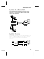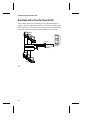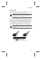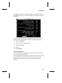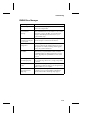
1
User’s Guide Fast Ethernet Network Interface Cards R R Adaptec, Inc. 691 South Milpitas Boulevard Milpitas, CA 95035 © 1998, Adaptec, Inc. All rights reserved. Adaptec and the Adaptec logo are trademarks of Adaptec, Inc. which may be registered in some jurisdictions. Printed in Singapore STOCK NO.: 511472-00, Rev. B BKB 3/98 Fast Ethernet Network Interface Cards User’s Guide R Copyright © 1998 Adaptec, Inc. All rights reserved. No part of this publication may be reproduced, stored in a retrieval system, or transmitted in any form or by any means, electronic, mechanical, photocopying, recording or otherwise, without the prior written consent of Adaptec, Inc., 691 South Milpitas Blvd., Milpitas, CA 95035. Trademarks ™ Adaptec, the Adaptec logo, ANA, and Duralink Failover are trademarks of Adaptec, Inc. which may be registered in some jurisdictions. Windows NT is a trademark, and Windows and Windows 95 are registered trademarks of Microsoft Corporation in the U.S. and other countries used under license. All other trademarks are owned by their respective owners. Changes The material in this document is for information only and is subject to change without notice. While reasonable efforts have been made in the preparation of this document to assure its accuracy, Adaptec, Inc. assumes no liability resulting from errors or omissions in this document, or from the use of the information contained herein. Adaptec reserves the right to make changes in the product design without reservation and without notification to its users. Adaptec Technical Support and Services If you have questions about installing or using your Adaptec product, check this user’s guide first—you will find answers to most of your questions here. If you need further assistance, please contact us. We offer the following support and information services: Electronic Support Technical information, including product literature, answers to commonly asked questions, information on software upgrades and other topics is available electronically through the following: ■ Adaptec World Wide Web (WWW) site at http://www.adaptec.com. ■ File Transfer Protocol (FTP) server at ftp.adaptec.com. ■ CompuServe Adaptec Forum at GO ADAPTEC. ■ Adaptec USA Bulletin Board Service (BBS) at 408-945-7727; supports up to 28,800 bps (bits per second), 8 data bits, 1 stop bit, no parity. No product literature is available on the Adaptec BBS. ■ Interactive Fax System at 408-957-7150; available 24 hours a day, 7 days a week. ii Technical and Product Support ■ For technical support and information about many of Adaptec’s electronic support services, call 800-959-7274 or 408-945-2550, 24 hours a day, 7 days a week. ■ To use the Adaptec Interactive Support System, call 800-959-7274 or 408-945-2550, 24 hours a day, 7 days a week. The system prompts you with questions regarding your problem and then provides step-by-step troubleshooting instructions. ■ To speak with a product support representative, call 408-934-7274, M–F, 6:00 A.M. to 5:00 P.M., Pacific Time. After hours, on weekends, and on holidays, product support is also available for a fee at 800-416-8066. Sales and Ordering Information ■ For sales information, call 800-959-7274 or 408-945-2550, M–F, 6:00 A.M. to 5:00 P.M., Pacific Time. ■ To order Adaptec software and SCSI cables, call 800-442-7274 or 408-957-7274, M-F, 6:00 A.M. to 5:00 P.M., Pacific Time. ■ To request additional documentation for Adaptec products, call 800-934-2766 or 510-732-3829, M–F, 6:00 A.M. to 5:00 P.M., Pacific Time. Class A Device Certification Statements Federal Communications Commission Radio Frequency Interference Statement WARNING: Changes or modifications to this unit not expressly approved by the party responsible for compliance could void the user’s authority to operate the equipment. This equipment has been tested and found to comply with the limits for a Class A digital device, pursuant to Part 15 of the FCC rules. These limits are designed to provide reasonable protection against harmful interference when the equipment is operated in a commercial environment. This equipment generates, uses, and can radiate radio frequency energy, and if not installed and used in accordance with the instruction manual, may cause harmful interference to radio communications. Operation of this equipment in a residential area is likely to cause harmful interference in which case the user will be required to correct the interference at his or her own expense. This device complies with part 15 of the FCC rules. Operation is subject to the following two conditions: (1) this device may not cause harmful interference and (2) this device must accept any interference received, including interference that may cause undesired operation. Canadian Compliance Statement This Class A digital apparatus meets all requirements of the Canadian Interference-Causing Equipment Regulations. Cet appareil numérique de la classe A respecte toutes les exigences du Règlement sur le matérial brouilleur du Canada. European Compliance Statement WARNING: This is a Class A product. In domestic environments this product may cause radio interference in which case the user may be required to take adequate measures. iii Class B Device Certification Statements Federal Communications Commission Radio Frequency Interference Statement WARNING: Changes or modifications to this unit not expressly approved by the party responsible for compliance could void the user’s authority to operate the equipment. This equipment has been tested and found to comply with the limits for a Class B digital device, pursuant to Part 15 of the FCC rules. These limits are designed to provide reasonable protection against harmful interference in a residential installation. This equipment generates, uses, and can radiate radio frequency energy, and if not installed and used in accordance with the instruction manual, may cause harmful interference to radio communications. However, there is no guarantee that interference will not occur in a particular installation. However, if this equipment does cause interference to radio or television equipment reception, which can be determined by turning the equipment off and on, the user is encouraged to try to correct the interference by one or more of the following measures: ■ Reorient or relocate the receiving antenna. ■ Increase the separation between equipment and receiver. ■ Connect the equipment to an outlet on a circuit different from that to which the receiver is connected. ■ Consult the dealer or an experienced radio/television technician for help. ■ Use a shielded and properly grounded I/O cable and power cable to ensure compliance of this unit to the specified limits of the rules. This device complies with part 15 of the FCC rules. Operation is subject to the following two conditions: (1) this device may not cause harmful interference and (2) this device must accept any interference received, including interference that may cause undesired operation. Adaptec, Inc. ANA-6911A/TX ANA-6911A/TXC ANA-6901 ANA-6901/C ANA-6944A/TX Tested To Comply With FCC Standards FOR HOME OR OFFICE USE Canadian Compliance Statement This Class B digital apparatus meets all requirements of the Canadian Interference-Causing Equipment Regulations. Cet appareil numérique de la classe B respecte toutes les exigences du Règlement sur le matérial brouilleur du Canada iv European Compliance Statement WARNING: This is a Class B product. In domestic environments this product may cause radio interference in which case the user may be required to take adequate measures. Safety Standards These products meet the following national and international regulations: ■ UL 1950 Standard for Safety of Information Processing and Business Equipment ■ IEC 950 Safety of Information Technology Equipment in Electrical Business Equipment CAN/CSA-C22.2 # 950 Safety of Information Technology Equipment including Electrical Business Equipment To ensure safe operating conditions, it is recommended that these products be installed in UL Listed computers. ■ v ▼ ▼ ▼ ▼ 1 Contents Getting Started Fast Ethernet 1-2 Duralink Failover 1-2 Supported Platforms and NICs 1-2 Adaptec NICs 1-3 System Requirements 1-5 Conventions and Advisories 1-5 PART 1: Installing NIC’s 2 Installing Your NIC Installing the NIC 2-1 Connecting to Your Network Cable 2-2 Connecting the Cable 2-2 LED Activity Indicators 2-2 Configuring the PCI NIC 2-3 PART 2: Installing LAN Drivers 3 Installing LAN Network Drivers Drivers 3-2 Full Duplex Support 3-3 vii Fast Ethernet Network Interface Cards 4 NetWare NetWare 4.1x 4-1 Removing Previously Configured Drivers 4-2 Adding NIC Drivers 4-2 Configuring the Ports 4-3 Configuring Protocols 4-4 Netware 3.12 4-5 Removing Previously Configured Drivers 4-5 Adding NIC Drivers 4-6 Configuring Ports 4-6 5 Windows Windows NT 4.0 5-1 Removing Previously Configured Drivers 5-1 Adding NIC Drivers 5-2 Configuring Ports 5-3 Configuring Protocols 5-3 Windows 95 5-4 Removing Previously Installed Drivers 5-4 Go to the system directory and remove any driver and supporting files related to EMPCI. 5-4 Adding NIC Drivers 5-4 Configuring Ports 5-5 Configuring Protocols 5-5 6 UNIX SCO OpenServer 5.0 6-1 Adding NIC Drivers 6-1 Configuring Ports 6-2 Configuring Protocols 6-2 viii Contents SCO UnixWare 6-3 Removing Previously Configured Drivers 6-3 Adding NIC Drivers 6-3 Configuring Ports 6-4 Configuring Protocols 6-4 Reconfiguring Ports and Protocols 6-5 7 IBM OS/2 IBM OS/2 Warp Versions 7-1 Adding NIC Drivers 7-1 Configuring Ports 7-2 Configuring Protocols 7-2 PART 3: Installing Duralink Failover Drivers 8 Network Configuration Examples Single Hub or Switch on an Ethernet Segment 8-2 Dual Hubs 8-2 Dual Hubs with an Ethernet Switch 8-3 Dual Hubs with Routers 8-3 Dual Hubs with a Four-Port Quartet NIC 8-4 9 Installing Duralink Drivers for Windows NT Installation Overview 9-1 Removing Existing Adaptec Ethernet NICs 9-2 Adding NIC Drivers 9-3 Configuring Ports 9-5 Configuring Failover Pairs 9-6 Configuring Protocols 9-8 Monitoring Failover Pairs 9-8 Changing NIC Configuration 9-9 ix Fast Ethernet Network Interface Cards 10 Installing Duralink Drivers for NetWare Installation Overview 10-1 Removing Previously Configured Drivers 10-2 Fresh NetWare Installation 10-2 Initial Installation and Configuration of Duralink Failover 10-3 Installing the Failover Software using fosetup 10-3 Configuring Ports 10-4 Setting Failover Pairs 10-5 Configuring Protocols 10-7 Viewing Configuration 10-9 Saving Configuration Changes 10-9 Viewing System Status Using fostatus.nlm 10-10 Network Client Setup 10-12 Reconfiguring Using foconfig.nlm 10-12 Managing NICs by SNMP 10-13 Installing and Uninstalling Software 10-13 A Cables and LEDs Connection Types A-2 Cable Requirements A-3 Twisted Pair Cable Types A-4 Straight-through Cable A-4 Crossover Cable A-5 Pinout and Color Requirements A-6 Diagnostic LEDs A-8 x Contents B Troubleshooting Running EMDIAG B-2 Using EMDIAG for PCI NICs B-2 EMDIAG PCI Main Menu B-2 Troubleshooting B-9 Isolating Faulty Hardware B-9 Frequently Asked Questions B-10 EMDIAG Error Messages B-11 C Identifying Ports Installing 2 Network Cards C-2 Installing 3 Network Cards C-5 Index xi ▼ ▼ ▼ ▼ 1 Getting Started This document contains information about installing and configuring the Adaptec PCI Ethernet and Fast Ethernet network interface cards (NIC’s). The following describes the sections in this document: Part 1, Installing NIC’s, describes how to install your Adaptec NIC. Part 2, Installing LAN Drivers, describes how to install and configure LAN drivers on various operating systems. Part 3, Installing Duralink Failover Drivers, describes how Duralink Failover works and adds value to your network. It gives instructions for installing Duralink Failover drivers for Windows NT-based servers and NetWare-based servers. 1-1 Fast Ethernet Network Interface Cards Fast Ethernet Fast Ethernet is a networking standard defined by the Institute of Electrical and Electronic Engineers (IEEE) in their IEEE 802.3u Specification. Fast Ethernet runs at 100 Mbps or at 200 Mbps in Full Duplex mode. Fast Ethernet uses the same Carrier Sense Multiple Access with Collision Detection (CSMA/CD) architecture used on 10BASE-T and 10BASE-2 10 Mbps network specifications, which allows for easy integration with existing networks. Duralink Failover Duralink™ Failover provides protection from system failures on Fast Ethernet servers running mission-critical applications. During a port failure, Duralink Failover keeps the connection to the server established by moving all traffic on the affected segment to a standby Network Interface Card (NIC) or port. When a failure is detected on the primary port, that port is disabled and a secondary port takes over to carry the load, and keeps the network running without interruption. This Failover operation occurs when any of the following conditions exist: ■ There is a link loss ■ A watchdog timer expires ■ An abnormal hardware interrupt occurs ■ Abnormal Send/Receive counters, such as too many collisions or errors, occur on the segment Supported Platforms and NICs Duralink Failover is supported for Windows NT™ and Novell Netware-based servers. Duralink Failover is compatible with Adaptec ANA™-6911A single port NIC, ANA-6922A dual port NIC, and ANA-6944A quad port NIC. 1-2 Getting Started Adaptec NICs The Adaptec PCI Ethernet and Fast Ethernet NICs currently includes the following products: ■ 10/100 AutoSensing NICs - support autosensing between 10 and 100 Mbps line speeds. The NICs support universal cable connectivity with RJ-45 and BNC connectors. They support Duralink Failover protection. Single RJ-45 Port ANA-6911A ■ Duo NICs - offers two high-performance Ethernet/Fast Ethernet ports on a single NIC. Each port runs at independent speeds for maximum flexibility. The NICs support Full Duplex to deliver speeds up to 400 Mbps cumulative throughput. They support Duralink Failover protection. Port 1 Port 2 ANA-6922 1-3 Fast Ethernet Network Interface Cards ■ Quartet NICs - provide four separate Fast Ethernet ports on a single NIC. Each port runs at independent speeds for maximum flexibility. The NICs support Full Duplex on UTP for up to 800 Mbps throughput on one NIC. They support Duralink Failover protection. Port 1 Port 2 Port 3 Port 4 ANA-6944A ■ Fiber Optic NICs - support Multimode Fiber (MMF) and cabling distances from 400 meters to 2 kilometers. They are available with SC (push on) or ST (twist on) connectors. The NICs support Full Duplex for speeds of up to 200 Mbps cumulative throughput. Fiber ST Port ANA-6910 1-4 Getting Started System Requirements The minimum system requirements for using the Adaptec NIC and for running the EMDIAG Diagnostics utility are as follows: System Component Requirements PCI NIC Available bus mastering PCI slot; most recent PCI system BIOS recommended Quartet & Duo NICs with Windows NT System BIOS supporting PCI-to-PCI bridge chip EMDIAG program MS-DOS 3.3 or later Conventions and Advisories This document includes the following typographic conventions. Bold Used for keystrokes (press the Enter key) and for options you are directed to select from a menu or list (select Configuration Status from the main menu). Helvetica Used for operator entry that you must type exactly as shown (a:\emdiag) and for messages that appear on the screen (Performing Automatic Media Detection). Helvetica Italics Used as a place holder for text you must determine and type (drive = boot drive letter) and for program and file names that appear in body text (the readme.txt file). 1-5 Fast Ethernet Network Interface Cards This document includes three kinds of advisories. Note: Notes are reminders, tips, or suggestions that might simplify the procedures included in this document. ! Caution: Cautions alert you to actions that might cause damage to your system or your data. WARNING: Warnings alert you to actions that might cause injury to you or someone else. Always use care when handling any electrical equipment. To avoid injury to people or damage to equipment and data, be sure to follow the cautions and warnings in this document. Adaptec does not claim to have included in this document every condition or situation that might require a caution or warning notice. Be sure to consult the documentation for your computer and any connected equipment when you are installing the equipment or changing its configuration. WARNING: Always use caution when handling electrical equipment! ❒ 1-6 ▼ ▼ ▼ ▼ Part 1 Installing NIC’s ▼ ▼ ▼ ▼ 2 Installing Your NIC This chapter describes how to install and configure your Adaptec NIC in your computer. The following procedures are covered: ■ Installing the NIC on page 2-1 ■ Connecting to Your Network Cable on page 2-2 ■ Configuring the PCI NIC on page 2-3 Installing the NIC WARNING: Before you start, turn OFF power to the PC and disconnect the power cord. Then ground yourself by touching an unpainted surface of the PC case. 1 Remove the cover from your computer, following the manufacturer’s instructions. 2 Carefully lift the NIC out of its antistatic container. Determine the model by looking at the model name on the NIC. Check the NIC for any visible signs of damage which may have occurred during shipment. If you find a problem, immediately notify your network supplier and the shipping service which delivered your NIC. 3 Locate an unused PCI expansion slot. Unscrew the bracket screw and remove the expansion slot bracket that covers the card-slot opening. 2-1 Fast Ethernet Network Interface Cards Note: PCI slots and NICs come in two varieties, 3.3-volt and the more common 5 volt. All Adaptec PCI NICs support 5-volt slots. Some models also support 3.3-volt slots. To improve performance with the multiport NICs, install these NICs in PCI Bus 0. 4 Insert the NIC into the expansion slot, pressing down firmly until the bus contacts are seated in the slot. Secure the NIC in the expansion slot with the screw removed in Step 3. 5 Replace the computer’s cover back on the computer. 6 Reconnect all devices and cables. Connecting to Your Network Cable Connecting the Cable Cable requirements for Adaptec NICs vary according to network speed, cabling standard, and the connector to be used. See Appendix A, Cables and LEDs for detailed information on cabling. After making sure you have appropriate cabling, connect the cable to the NIC connector. (For multiport NICs, connect a cable for each port.) Note: If you load a Quartet or Duo NIC and a port does not have a cable attached, you may receive a startup message on your server. This is normal and does not affect performance. LED Activity Indicators Diagnostic Light Emitting Diodes (LEDs) provide information about link status and network activity. For detailed information on the LED display for your NIC see Appendix A, Cables and LEDs. 2-2 Installing Your NIC Configuring the PCI NIC Your computer’s BIOS may determine available NIC resources and configure the Adaptec PCI NICs automatically. However, depending on your system, you may need to configure the PCI BIOS. To do this, enter your computer BIOS Setup and select Advanced Settings from the Main Menu. Make sure the following settings are made (your BIOS may not match the following options exactly): Option Setting PCI Slot Enabled Enable all PCI slots in your system. Bus Mastering Enable PCI bus mastering for the slot(s) to be used by the NICs. PCI INTA Assign an ISA interrupt (10, 11, 12, etc.) to PCI Interrupt Vector A. PCI INT Vector Assign PCI Interrupt Vector A to the PCI slot(s). PCI Bus Latency Set to a value between 40 and 80. Note: Quartet and Duo NICs use the DEC PCI-to-PCI bridge chip. If your system’s BIOS does not support the PCI-to-PCI bridge chip these NICs will not be configured properly. Contact your computer manufacturer to obtain a new BIOS version that supports the PCI-to-PCI bridge chip. ❒ 2-3 ▼ ▼ ▼ ▼ Part 2 Installing LAN Drivers ▼ ▼ ▼ ▼ 3 Installing LAN Network Drivers The following chapters describe how to install network drivers and enable Full Duplex support for the following network operating systems: ■ NetWare 4.1x ■ NetWare 3.12 ■ Windows NT 4.0 ■ Windows 95 ■ SCO UnixWare ■ SCO OpenServer ■ IBM OS/2 Warp Versions Instructions for other operating systems are available in the readme.txt files of their respective drivers. 3-1 Fast Ethernet Network Interface Cards Drivers The LAN drivers available on the included diskettes are as follows: Diskette 1 Diskette 2 NetWare Server Windows NT for Intel NetWare Client32 Windows 95 SCO Unixware NDIS DOS SCO Openserver DOS ODI OS2 NDIS Windows NT for Alpha Diagnostics Additional drivers are available directly from Adaptec or your operating system vendor. See the readme.txt file for details. Note: Always use the latest driver version available for your NIC. Drivers are updated regularly on Adaptec’s World Wide Web, FTP, BBS, and CompuServe forum sites to provide enhanced performance and new features. See Technical and Product Support on page iii. 3-2 Installing LAN Network Drivers Full Duplex Support To implement Full Duplex on your network, you need both a NIC and a switch that supports Full Duplex. Full Duplex support allows a NIC to send and receive data at the same time, doubling available bandwidth. Note: Full Duplex can also be enabled point-to-point with a crossover cable instead of a switch. Installation instructions in the following chapters describe how to enable Full Duplex. Additional information can be found in the readme.txt file. Adaptec PCI 10 Mbps NICs support Full Duplex on twisted-pair cabling; Adaptec PCI TX NICs support Full Duplex at both 10 Mbps and 100 Mbps; Adaptec PCI T4 NICs support Full Duplex at 10 Mbps only. Note: BNC connections do not support Full Duplex. ❒ 3-3 ▼ ▼ ▼ ▼ 4 NetWare This chapter describes how to install LAN drivers for NetWare. The Novell NetWare driver, \nwserver\empci.lan is used with NetWare 4.1x servers, NetWare 3.12 and NetWare 4 SFT III. Note: An Adaptec LAN adapter cannot be used as the MSL NIC in an SFT-III environment. NetWare 4.1x This section describes how to install the LAN drivers for NetWare 4.1x. To install the Duralink Failover drivers refer to Chapter 10, Installing Duralink Drivers for NetWare. NetWare 4.10 requires two patches to enable the ODI 3.3 support. These can be found at http://support.novell.com. Download the server patch 410pt7.exe and the ODI 3.3 NLMs from the LAN driver patch landr9.exe. ODI 3.3 patches are not required for NetWare 4.11. INETCFG.NLM is the recommended utility to properly install and configure the NetWare driver. 4-1 Fast Ethernet Network Interface Cards Removing Previously Configured Drivers To ensure that no conflicts exist between previously installed drivers and the NetWare driver, delete all previously installed Adaptec drivers. This is done by following the procedures below: 1 At the server prompt, type load inetcfg and press Enter to display the Internetworking Configuration (INETCFG) window. 2 3 Select Boards and press Enter. A list of network NICs appears. 4 5 6 7 Press ESC. Delete all existing Adaptec EMPCI boards by selecting each and pressing DEL. Select Manage Configurations. Select Edit Autoexec.ncf. Highlight and delete any commands containing the strings: EMPCI fover.ncf failover.ncf loadbal.ncf ! 8 Caution: Be sure to remove only these commands. Errors may result in problems with other programs or system components! Press Esc and save the changes. Adding NIC Drivers 1 2 From the INETCFG main menu, select Boards and press Enter. 3 Press Ins again and insert Diskette 1 containing the Netware driver. 4 Specify the correct path to the new empci.lan file (for example, a:\nwserver\empci.lan). 4-2 Press Ins to add a new driver. A list of available LAN drivers appears. NetWare Configuring the Ports 1 2 Select the new empci from the updated list of NICs. Type in a name for the newly added NIC. Note: When choosing a name for the NIC, you should include a reference to the index number assigned to that NIC (See Step 3 below). This will help you identify the NIC when configuring it. See Appendix C, Identifying Ports for tips on identifying NICs. 3 Specify the index number in the next field (1 is the default for the first board; set the next board at 2, and so forth). Note: Each port must be assigned a unique index number. 4 Specify the connection type. Autodetect Default is recommended. For an explanation of options see Connection Types on page A-2. 5 6 Press Esc and save the configuration. For each additional port, press Ins at the Boards screen and repeat Steps 1 - 5. 4-3 Fast Ethernet Network Interface Cards Configuring Protocols 1 From the INETCFG main menu, select Protocols. Enable the appropriate protocols for your network. 2 3 Press Esc to exit, saving your protocol configuration. 4 Select your configuration settings. Consult your network administrator or NetWare documentation for details. 5 Repeat Steps 3 and 4 to bind multiple frame types or protocols to one port if needed. From the INETCFG main menu, select Bindings. Highlight the NIC to bind and press Ins. Note: It is not necessary to bind multiple frame types and protocols for each port. 6 Press Esc and save your configuration as you exit. Press Esc again to exit the INETCFG utility. 7 At the server console type down and then type restart system to start the new configuration. 8 When finished booting, type config at the console prompt to confirm your configuration settings. 4-4 NetWare Netware 3.12 This section describes how to install the LAN drivers for NetWare 3.12. The Novell NetWare driver, \nwserver\empci.lan is used with NetWare 3.12 servers. The driver must be installed manually. NetWare 3.12 requires one patch to enable ODI 3.3 support. Download the landr9.exe patch from http://support.novell.com. Removing Previously Configured Drivers Before adding new NICs, commands referencing previously installed Adaptec NICs and drivers must be removed from the autoexec.ncf file. 1 At the system command line prompt type load edit sys:\system\autoexec.ncf. 2 Remove any commands containing the following strings: EMPCI failover.ncf fover.ncf loadbal.ncf ! 3 Caution: Be sure to remove only these commands. Errors may result in problems with other programs or system components! Press Esc to save and return to the command line prompt. 4-5 Fast Ethernet Network Interface Cards Adding NIC Drivers To add NIC drivers you must copy the Adaptec driver from a client to the Server’s system directory. To do this 1 2 Insert Diskette 1 in the server’s drive A. 3 4 Type bind ipx empci and enter a network number. 5 6 Insert Diskette 1 in the client’s floppy drive. Type load a:\nwserver\empci and select a port index number. (see Appendix C, Identifying Ports). Connect a client to the server’s NIC and log on from the client as a supervisor. Copy the file empci.lan from the directory a:nwserver on the driver diskette of the client to the sys:system directory of the NetWare server. Configuring Ports To configure the new NICs you must edit the autoexec.ncf file manually. Consult your system administrator and NetWare documentation for further information. 1 At the system command line prompt type load edit syst:\system\autoexec.ncf. 2 Add the appropriate load and bind commands. Following are two sample configurations. The exact configuration will vary depending on your needs. ■ This configuration binds the IPX protocol to two seperate ports. Since no frame type is specified, the default Ethernet_802.3 will automatically be assigned for both. This is the simplest configuration. LOAD EMPCI NAME=S1 INDEX=6 BIND IPX S1 net=a22 LOAD EMPCI NAME=S2 INDEX=7 BIND IPX S2 net=a33 Note: A unique index number must be assigned to each port. 4-6 NetWare ■ This configuration binds multiple frames and protocols to the same port. LOAD EMPCI NAME=S1 FRAME=Ethernet_802.2 INDEX=6 BIND IPX S1 net=a22 LOAD EMPCI NAME=S2 FRAME=Ethernet_802.2 INDEX=6 LOAD TCPIP BIND IP S2 address=100.100.100.100 mask=FF.FF.FF.0 LOAD EMPCI NAME=S3 FRAME=Ethernet_II INDEX=6 BIND IPX S3 net=b24 LOAD EMPCI NAME=S4 FRAME=Ethernet_SNAP INDEX=6 BIND IPX S4 net=a34 Note: In order to establish which port a protocol is assigned to, you must assign a different name to each frame set. The index number must remain the same for each port regardless of how many frame types or protocols are assigned to it. 3 4 Press Esc to save and return to the command line prompts. Reboot for the new configurations to take effect. ❒ 4-7 ▼ ▼ ▼ ▼ 5 Windows This chapter describes how to install LAN drivers for Window NT and Windows 95. For additional information on installing LAN drivers for Windows’ environments refer to the readme.txt file. If you are using an Alpha Server please refer to the NT for Alpha readme.txt file. Windows NT 4.0 This section describes how to install LAN drivers for Windows NT. To install Duralink Failover drivers refer to Chapter 9, Installing Duralink Drivers for Windows NT. The Windows NT 4.0 driver is in the \winnt\i386 directory. Note: These instructions are for Windows NT 4.0 only. To install drivers for Windows 3.51, see the readme.txt file. Removing Previously Configured Drivers If there are no previously installed Adaptec NICs go to Adding NIC Drivers on page 5-2. Otherwise follow these steps: 1 2 3 4 5 Boot your system with Windows NT 4.0 Double-click the My Computer icon. Double-click the Control Panel icon. Double-click the Network icon. Click the Adapters tab in the Network Setup dialog box. 5-1 Fast Ethernet Network Interface Cards 6 To remove any currently installed Adaptec NIC drivers, highlight the driver, click Remove, then click OK. Repeat until all Adaptec NIC drivers are removed. 7 8 Click Close to close the Network dialog box. Click Yes to restart your computer. Note: When you restart Windows NT, a message may indicate that at least one service failed to start. This message will not appear after you add the new drivers in the following steps. Click OK. Adding NIC Drivers 1 2 3 4 Double-click the My Computer icon. Double-click the Control Panel icon. Double-click the Network icon. In the Network Setup dialog box select the Adapters tab. Note: Do not allow Network setup to autodetect the network NIC. 5 6 7 Click Add. 8 From the Select OEM Option dialog box select Adaptec PCI Ethernet Adapter. Click OK. Click Have Disk. At the prompt Insert disk with software provided by the software or hardware manufacturer, insert Diskette 2. Enter the path to the directory where the Windows NT driver and OEMSETUP file are located. Click OK. The driver configuration window is now displayed. 5-2 Windows Configuring Ports 1 From the Driver Configuration dialog box, select the appropriate connection type for your network. Autodetect Default Connection is the recommended choice. For an explanation of possible options see Connection Types on page A-2. Click OK. 2 The Driver Configuration dialog box will display again for each NIC installed. Repeat Step 1 for each of these NICs. Note: For multiport NICs, the Driver Configuration dialog box will display again for each port. Each NIC can be identified by its unique PCI Bus/PCI Slot number. 3 If SNMP has not been set up on this computer you will receive the following Setup message: Install the NT SNMP service and use configure option to configure Server related MIBs. Click OK. Configuring Protocols 1 2 3 In the Network Setup dialog box click the Bindings tab. 4 5 Click OK. In the show bindings drop-down box, highlight all protocols. Highlight the protocols you wish to bind and click Enable. Disable all other protocols. Click Finish in the Network Settings dialog box and reboot your system for the settings to take effect. 5-3 Fast Ethernet Network Interface Cards Windows 95 This section describes how to install LAN drivers for Windows 95. The Windows 95 driver is on Diskette 2 in the \win95 directory. Removing Previously Installed Drivers If you are replacing or upgrading an existing NIC you need to remove the previously installed NICs. This will prevent any driver conflicts. If you are adding a NIC go to Adding NIC Drivers. 1 2 Go to the Control Panel and double-click the Network icon. Remove the driver(s) from the list of installed components by highlighting the driver(s) and selecting Remove. Go to the system directory and remove any driver and supporting files related to EMPCI. Adding NIC Drivers To add NIC drivers 1 In the Network dialog box, select Add, and highlight Adapter as the network component type. Click Add to go to Select Network Adapter window. 2 3 Click Have Disk. Put the diskette in drive A and specify a:\win95 as the path to the driver. You will be prompted to select the model of your Adaptec NIC. 4 Select the appropriate model and click OK. You will return to the Control Panel’s network dialog box. 5 5-4 Make sure that at least one network client and one protocol are installed, in addition to the Adaptec adapter driver now listed under Control Panel/Network. See Configuring Protocols on page 5-5 Windows Configuring Ports To configure NICs 1 In the Network dialog box, highlight the NIC in the list of installed drivers and select Properties. 2 From the Properties dialog box, select Advanced, then choose the appropriate connection type. For an explanation of options see Connection Types on page A-2. Configuring Protocols 1 From the Properties dialog box, highlight Protocols and click Add. 2 3 4 Highlight Protocol and click Add again. 5 Select the type of protocol you wish to bind and click OK. After you have made all changes, click OK in the Network dialog box. Windows 95 will prompt you to restart your system. Click Yes. ❒ 5-5 ▼ ▼ ▼ ▼ 6 UNIX This chapter describes the installation of Unix drivers. The drivers are located on Diskette 1. SCO OpenServer 5.0 This section describes how to install LAN drivers for SCO OpenServer 5.0. Adding NIC Drivers 1 Power OFF your system and install the adapter in a PCI bus mastering slot. 2 Boot the system with SCO OpenServer 5.0 and login as the root user. 3 4 5 6 7 8 Double-click the Software Manager Icon on the desktop. 9 From the menu, select Software and then Install New. Press Continue. Insert Driver Diskette 1 in drive A and click Continue. Select Full installation. After scrolling through the readme, click OK to complete the installation. Exit the Software Manager by clicking Host and then Exit. 6-1 Fast Ethernet Network Interface Cards Configuring Ports 1 Enter the System Administration Folder and double-click the Networks folder. 2 3 4 Double-click the Network Configuration Manager icon. 5 Select the serial media type and click OK. Autosense is the recommended choice. For an explanation of possible options for media type see Connection Types on page A-2. From the Hardware menu, select Add new LAN Adapter. Select Adaptec ANA-69xx Fast Ethernet Controller and click Continue. Note: If you are using a BNC connector you must select it. Autosense will not detect it. 6 Click OK again and continue with Configuring Protocols. Configuring Protocols Note: The Adaptec SCO OpenServer driver has not been tested with IPX/SPX, NetBeui or SCI OpenServer 5.0.4. To ensure maximum efficiency use the TCP/IP protocol. 1 In the Add Protocol window, highlight SCO TCP/IP and click ADD. 2 3 Enter the protocol configurations and click OK. 4 When all ports have been configured, click Exit from the Hardware menu. 5 Follow the online prompts for re-linking the kernel. For multiple NICs or multiple ports on a multi-port NIC go to Step 3 in Configuring Ports and configure the ports and protocols for each port. After the kernel is re-linked the system returns to the Network screen. 6 6-2 Reboot the system. UNIX SCO UnixWare This section describes how to install LAN drivers for UnixWare. The driver for this operating system is located on Diskette 1 in the /UNIXWARE directory. The SCO UnixWare driver supports up to four ports for the same type of NIC. It does not support a mixture of NICs at the same time. Note: All commands in Unix are case sensitive. Be sure to type all commands exactly as shown. Removing Previously Configured Drivers Before adding the Adaptec NIC you must first remove any previous driver package, then reinstall it for the new NIC. 1 As the root user, remove the package by typing pkgrm EMPCI. Follow the online prompts to remove the package. 2 Shut down the system, replace the NIC and reboot. Adding NIC Drivers 1 After booting up with UnixWare, press contrl/alt/sys rq and then P to go to the system command line prompt. 2 3 Login as the root user. Insert Diskette 1 in drive A. To copy the compressed driver file from the floppy drive to the local hard disk, type doscp a:/unixware/EMPCI.Z /tmp/EMPCI.Z 4 To uncompress the file type uncompress /tmp/EMPCI 6-3 Fast Ethernet Network Interface Cards Configuring Ports 1 At the system command line type pkgadd -d /tmp/EMPCI 2 After uncompressing the files the following message appears: The following packages are available: 1 EMPCI Type 1 to select EMPCI Note: Only one choice (1 EMPCI) is given here regardless of how many NICs are installed. 3 Now a list of Adaptec NICs is displayed. Select the NIC you wish to configure and press Enter. Note: For a multiport NIC there will be multiple device listings. Each port must be configured. 4 Select the connection type and press Enter. For an explanation of possible options see Connection Types on page A-2. 5 If prompted, select Half Duplex or Full Duplex and press Enter. 6 The system will now automatically detect the next port. Repeat Steps 4 - 5 for each port. Configuring Protocols 1 At the system command line prompt type /etc/confnet.d/configure -i 2 3 4 5 6-4 Select the NIC to configure and press Enter. Follow the online prompts to configure the protocols. Repeat Step 1 - 3 for each port. Reboot the system. UNIX Reconfiguring Ports and Protocols Follow these steps to reconfigure existing NICs. 1 At the command line prompt type empcikwd 2 Select Display to reconfigure the connection type or select Set to reconfigure the protocols. 3 4 Follow the online prompts to make the configuration changes. Relink and reboot the system. ❒ 6-5 ▼ ▼ ▼ ▼ 7 IBM OS/2 IBM OS/2 Warp Versions This section describes how to install LAN drivers for IBM OS/2 Warp versions. The driver for these operating systems is on Diskette 1 in the \ndis.os2 directory. Adding NIC Drivers 1 2 Install the Adaptec NIC and reboot the system. 3 4 Select Install. 5 6 7 After the OS/2 driver is copied from the diskette, select OK. 8 In the LAPS dialog box, under the Network Adapters window, highlight Adaptec 69xx Ethernet PCI Adapter Family and click Add. Repeat this for each port on a multi-port NIC or for multiple NICs. On your desktop, double-click the MPTS (Multi-Protocol Transport Services) icon or type mpts at the system command line prompt. Select Install Additional Network Drivers, and specify a:\ndis.os2 as the source. Select OK. Select Configure. Select LAN Adapters and Protocols (LAPS) and then click Configure. 7-1 Fast Ethernet Network Interface Cards Configuring Ports 1 To change the NIC configuration settings highlight the NIC to configure and click Edit. Note: There are three ways to gain information for each parameter: - select Range to see valid choices - press F1 to see parameters and default settings - select Help for additional details 2 Select the Tranciever type. For an explanation of possible options see Connection Types on page A-2 or press F1. 3 4 Specify Full or Half Duplex Specify the Index number. Note: Each port must be assigned a unique index number. 5 6 Make any other necessary changes and click OK. Repeat Steps 1 - 5 for each port. Configuring Protocols 1 Under Protocols, highlight the desired network protocol(s) and click Add. Note: The NetBios protocol is required for LAN Server and OS/2 Peer connections. If you selected IBM NetWare Requester Support from the Protocols box, you need to make the following configuration changes: – In the Current Configuration box, highlight IBM NetWare Requester and select Edit. – Change the Token-Ring Support Option to NO. 7-2 IBM OS/2 – Enable one or more of the listed Ethernet frame types by specifying YES in the appropriate boxes. (If you are not sure which frame type(s) are used on your NetWare network, enable all of them). – Change the Network NIC Address to the Ethernet address of your Adaptec NIC. This address must be different for each port. You can run emdiag.exe from your Adaptec driver diskette at an OS/2 command line prompt, and select Configuration Status, to display your NIC's Ethernet address. 2 Repeat Step 1 for each port or for binding multiple protocols to one port. 3 4 5 6 In the LAPS dialog box, select Close. 7 If using the TCP/IP protocol go to the command line prompt and type tcpcfg. Progress through the online prompts. 8 Shut down OS/2 and reboot for your network driver and protocol(s) to take effect. In the Multi-Protocol Transport Services dialog box, select Exit. Select Update CONFIG.SYS and then select Exit. If using Warp Connect or LAN Server software you must reestablish the dependency path between the NetBios protocol and the IBM software each time the NetBios protocol is reconfigured. To do this, run the Install program and progress through all of the online prompts. ❒ 7-3 ▼ ▼ ▼ ▼ Part 3 Installing Duralink Failover Drivers ▼ ▼ ▼ ▼ 8 Network Configuration Examples This chapter describes some typical network configurations using Duralink Failover. The primary and backup Adaptec NICs or ports reside in the server. Duralink Failover operates on these NICs to provide redundancy on the server. 8-1 Fast Ethernet Network Interface Cards Single Hub or Switch on an Ethernet Segment This configuration uses two NICs connected to a hub or switch on an Ethernet segment. With this configuration, Duralink Failover provides failover capability if one of the NICs fail. Ethernet Switch or Ethernet Hub Primary Server Clients Secondary Dual Hubs In this example, each NIC is connected to a separate hub to provide redundancy. If the hub port being used by the primary NIC fails, then the secondary NIC becomes active and all network traffic is immediately directed through it. Clients Ethernet Hub Primary Server Ethernet Hub Secondary Clients 8-2 Network Configuration Examples Dual Hubs with an Ethernet Switch This example shows how Duralink Failover provides network redundancy to a switched network. Ethernet switches provide network traffic segmentation. Clients Ethernet Hub Ethernet Switch Primary Server Ethernet Hub Secondary Clients Dual Hubs with Routers The following example shows how to set up Duralink Failover in a network configuration using routers. Routers provide WAN and LAN connectivity and allow physical network protocol redundancy. Router Ethernet Hub Primary Uplink Router Server Ethernet Hub Secondary 8-3 Fast Ethernet Network Interface Cards Dual Hubs with a Four-Port Quartet NIC This example shows port redundancy, using Duralink Failover, within a single four-port Quartet NIC. As shown in the illustration below, ports 1 and 3 are used as the primary ports to each Ethernet hub. Ports 2 and 4 are secondary ports connected to each hub. Clients Primary Ethernet Hub Port1 Port2 Server Port3 Port4 Ethernet Hub Clients ❒ 8-4 Secondary ▼ ▼ ▼ ▼ 9 Installing Duralink Drivers for Windows NT This chapter describes how to install Duralink Failover for Windows NT 4.0. Installation Overview The following procedures are covered in this chapter: ■ Removing Existing Adaptec Ethernet NICs on page 9-2 ■ Adding NIC Drivers on page 9-3 ■ Configuring Failover Pairs on page 9-6 Installation, configuration, and optional parameters for the software are updated regularly. The readme subdirectory contains supplemental installation instructions, as well as other up-to-date information pertaining to the software, and should be read prior to installing Duralink Failover. 9-1 Fast Ethernet Network Interface Cards To install the software: 1 2 3 4 Boot your system with Windows NT 4.0. Double-click the My Computer icon. Double-click the Control Panel icon. Double-click the Network icon. Note: If no drivers are currently installed for Adaptec PCI NICs, skip to Adding NIC Drivers on page 9-3. Removing Existing Adaptec Ethernet NICs In order to install the Adaptec Duralink Failover drivers, you must remove the Adaptec LAN drivers. To do so, follow these steps: 1 9-2 Click the Adapters tab in the Network dialog box. Installing Duralink Drivers for Windows NT 2 To remove any currently installed Adaptec NICs highlight the name, click Remove, then click OK. Repeat until all Adaptec NIC drivers are removed. 3 4 Click Close to close the Network dialog box. Click Yes to restart your computer. Note: When you restart Windows NT, a message may indicate that at least one service failed to start. This message will not appear after you add the new Duralink drivers in the following steps. Click OK. Adding NIC Drivers 1 2 3 4 Double-click the My Computer icon. Double-click the Control Panel icon. Double-click the Network icon. Click the Adapters tab in the Network dialog box. Note: Do not allow Network Setup to autodetect the installed NICs. 5 6 7 Click Add. Click Have Disk. At the prompt Insert disk with software provided by the software or hardware manufacturer, insert the Duralink Failover diskette in your floppy drive. Enter the path to the directory where the driver and oemsetup file are located (a:\winnt\i386 or b:\winnt\i386). Click OK. 9-3 Fast Ethernet Network Interface Cards 8 From the Select OEM Option list box, select Adaptec PCI Ethernet Adapter, and click OK. The program loads the Duralink Failover configuration utility for Windows NT. 9-4 Installing Duralink Drivers for Windows NT Configuring Ports Note: The following screen appears when first installing Adaptec NICs. 1 From the Adaptec New Hardware Found dialog box, select the port to configure from the New Adaptec Ports Available list box. 2 Choose the appropriate connection type for your network. Autodetect Default Connection is the recommended choice. For an explanation of possible options see Connection Types on page A-2. Note: The BNC connector is not supported by Duralink Failover. 3 4 Click OK. Repeat Steps 1 - 3 for each port. 9-5 Fast Ethernet Network Interface Cards Configuring Failover Pairs The following steps show how to group failover pairs. All available ports are listed in the Available Adaptec Ports list box. 1 Assign a port to the Primary Ports list box by clicking on a port in the Available Adaptec Ports list box to highlight the selection. Note: The driver numbering schemes for the ports (EMPCI1, EMPCI2, etc.) shown in the Configuration screen are not associated with the physical PCI slot numbers on the motherboard. 2 When a port has been highlighted, click on the top Add button. The port moves to the Primary Ports drop-down box. 3 Assign a Backup port to the Primary Port by selecting a port from the Available Adaptec Ports list box and clicking on the bottom Add button. To remove a failover pair, select the port in the Primary Ports drop-down box, and click Remove. 4 When you have completed setup of all failover pairs, click OK. 9-6 Installing Duralink Drivers for Windows NT 5 If SNMP has not been set up on your computer you will receive the following Setup Message: 6 7 Click OK. The Network dialog box displays the ports and their associated pairs. Pair names are shown in <brackets> to the right of the port name. In the following example, <Failover1> indicates that port 1 is the primary port of the pair named Failover. 9-7 Fast Ethernet Network Interface Cards Configuring Protocols If you plan to use TCP/IP, obtain your IP address and subnet information prior to installation. You may have a DHCP server that will provide the IP information automatically. If you are not sure if you have a DHCP server or what IP address to use, contact your network administrator. 1 2 3 In the Network Setup dialog box click the Bindings tab. In the show bindings drop-down box, highlight all protocols. Highlight the protocols you wish to bind and click Enable. Disable all other protocols. Note: Use reliable transport protocols like TCP/IP and IPX for reliable data transmission between the server and the clients. If you use NetBeui, make sure it is last in the protocol stack list. 4 5 Click OK. Click Finish in the Network Settings dialog box and reboot your system for the settings to take effect. Monitoring Failover Pairs There are two ways to monitor the status of Failover Pairs: ■ SNMP Manager—when failover occurs SNMP traps are sent to network management stations and error logs are updated through the operating system event log. To enable SNMP agents, compile the following MIB file on the SNMP management station: DURALINK.MIB ■ 9-8 Event Viewer Dialog Box—the local event viewer dialog box will log failover problems. Installing Duralink Drivers for Windows NT Changing NIC Configuration If you need to change the NIC configuration in your NT server or workstation (to delete, add, or move a NIC), follow these steps ■ Remove previously configured Adaptec NICs (see Removing Existing Adaptec Ethernet NICs on page 9-2. ■ Power down the system and then change the hardware. ■ Reinstall all NICs (see Adding NIC Drivers on page 9-3). ❒ 9-9 ▼ ▼ ▼ ▼ 10 Installing Duralink Drivers for NetWare This chapter describes how to install the Duralink Failover utility on a server running NetWare 4.1x/3.1x. Instructions in this section cover both initial installation from the fosetup.nlm file contained on the Duralink Installation Diskette, as well as instructions on changing the configuration using the foconfig.nlm utility (residing on the server after installation). Use foconfig or fosetup to install or configure Duralink Failover. Otherwise, fostatus may not show the proper configuration. Installation Overview The following procedures are covered in this chapter ■ Removing Previously Configured Drivers on page 10-2 ■ Initial Installation and Configuration of Duralink Failover on page 10-3 ■ Viewing System Status Using fostatus.nlm on page 10-10 ■ Network Client Setup on page 10-12 ■ Reconfiguring Using foconfig.nlm on page 10-12 Installation, configuration, and optional parameters for the Duralink Failover utility are updated regularly. The readme subdirectory contains supplemental installation instructions, as well as information about optional keywords. 10-1 Fast Ethernet Network Interface Cards Removing Previously Configured Drivers If you have installed Duralink or Adaptec Ethernet drivers prior to this installation, complete this section. This is to ensure that no conflicts exist between previously installed drivers and Duralink Failover. Do not install Duralink Failover 3.0 over 2.0. 1 Remove all load and bind commands related to EMPCI, failover.ncf, fover.ncf or loadbal.ncf from the autoexec.ncf. ! Caution: Be sure to remove only these commands. Errors may result in problems with other programs or system components! 2 3 4 At the server prompt, type load inetcfg and press Enter. 5 Press ESC to exit inetcfg. Select Boards and press Enter. Delete all existing EMPCI boards by selecting each and pressing DEL. Fresh NetWare Installation If you are loading NetWare on a new server, do not add a LAN/Ethernet adapter when prompted in the NetWare setup procedures. When prompted to add a LAN adapter, select No and continue with the NetWare installation. Then proceed to the following section. 10-2 Installing Duralink Drivers for NetWare Initial Installation and Configuration of Duralink Failover Configuration for Duralink Failover is done through a Setup program that is contained on the NetWare Duralink Installation Diskette. This program will install the necessary files required for running the program through NetWare onto your hard drive. The Setup program allows you to ■ Configure ports ■ Configure Failover Pairs—assigning names, deleting and adding ports to groups for load balancing ■ Configure protocols for stand-alone ports or groups ■ Update files Installing the Failover Software using fosetup At the prompt, type load a:\nwserver\fosetup. A message indicating the number of ports is displayed. Press Esc to enter the setup module. Netware Loadable Module Duralink Failover Setup V2.1 Main Menu Configure Ports Set Failover Pairs Configure Protocols View Configuration Install Software Uninstall Software Use arrow keys to move, <Enter> to Select, <ESC> to Exit. © Copyright 1998, Adaptec Inc. < F1> Help < F10> Abort Setup F Keys F1— provides on-line help for each screen. F10— allows you to abort any changes you have made from within the program and exit the utility. 10-3 Fast Ethernet Network Interface Cards Configuring Ports 1 Select the Configure Ports option from the Main Menu. Main Menu Configure Ports Set Failover Pairs Configure Protocols View Configuration Install Software Uninstall Software The program automatically adds or removes ports when new hardware is added or removed. After removing a NIC, you must reinstall and configure the driver for all ports. This is because the port index number relationship to the physical port location will have changed. Connection Type Status Empci1 Autodetect (default) Enabled Empci2 Autodetect (default) Enabled No. Port Name 1 2 Note: The driver numbering schemes for the ports (EMPCI1, EMPCI2, etc.) are not associated with the physical PCI slot numbers on the motherboard. It is recommended that you check physical connections against the port information displayed on the screen. See Appendix C, Identifying Ports for more information. 2 10-4 To set the connection type, select each port individually and press Enter. Installing Duralink Drivers for NetWare 3 Select the appropriate connection type for your network. Autodetect (default) is the recommended choice. For an explanation of possible options see Connection Types on page A-2. Note: The Thin (BNC) connector is not supported for Duralink Failover. Netware Loadable Module Duralink Failover Setup V2.1 Type of Connection No. Port Name 1 Empci1 2 Empci2 Autodetect (default) Connection Type 10 Mbps UTP/Half Duplex 10 Mbps UTP/Full Duplex Autodetect (default) 100 Mbps UTP/Half Duplex Autodetect (default) 100 Mbps UTP/Full Duplex Thin Use arrow keys to move, <Enter> to Select, <ESC> to go back to the previous menu. © Copyright 1998, Adaptec Inc. < F1> Help < F10> Abort Setup You can set configuration parameters but leave the settings Disabled for use at a later time by pressing Tab while the port is selected. 4 Press Esc when you have completed port configuration. Setting Failover Pairs 1 Select Set Failover Pairs from the Main Menu and press Enter. Main Menu Configure Ports Set Failover Pairs Configure Protocols View Configuration Install Software Uninstall Software 10-5 Fast Ethernet Network Interface Cards 2 Add a Failover Pair by pressing Ins. The program automatically assigns a default pair name. If previous pairs have been assigned, the new one is placed last in the list. The default naming convention is as follows: the first pair is assigned to Pair1, the next to Pair2, then Pair3, and so on. Netware Loadable Module Duralink Failover Setup V2.1 Failover Pair Name Pair1 List of Existing Pairs 1 Pair1 Set Failover Pairs Add/Remove Ports Set Failover Pair Name Display Existing Ports <INS> to Add, <DEL> to Remove, <ENTER> to Configure, <ESC> to go back to the previous menu. © Copyright 1998, Adaptec Inc. 3 < F1> Help < F10> Abort Setup Set Failover Pair Name— To assign a unique name to the group, select Set Failover Pair Name from the Failover Configuration menu and press Enter. Type the group name and press Enter. The new name appears at the upper right portion of the screen. 4 Add/Remove Ports— Add ports to a Failover Pair by selecting the Add/Remove Ports option from the Failover Pair Configuration menu and pressing Enter. You can add only two ports to a failover pair. If the Failover Pair is new, the Existing Ports dialog box will show No Ports Present. To add ports to a pair, press INS. Select ports from the Available Port(s) dialog and press Enter. As ports are selected, they will appear in the Existing Ports dialog box. The first port selected is the primary port for the pair. To set one of the selected ports as the primary port, select it from the Existing Ports dialog box, and press Enter. When all ports have been selected, press Esc to complete the change. 10-6 Installing Duralink Drivers for NetWare 5 Display Existing Ports— Select this option to view the ports associated with the pair. 6 7 Press Esc to complete the current pair. To create more groups, follow Steps 2 through 4 for each new pair. Note: Any ports not assigned to a failover pair will be used as standalone ports. Configuring Protocols These procedures allow you to configure the IP or IPX protocols for Failover Pairs and standalone ports. 1 Select Configure Protocols from the Main Menu. Main Menu Configure Ports Set Failover Pairs Configure Protocols View Configuration Install Software Uninstall Software A list of standalone ports and Failover Pairs are displayed. Standalone ports include a P reference and Failover Pairs include an F reference as shown in the figure below. List of Ports / Failover Pairs Stand-alone Ports 1 2 3 4 5 6 P P P P F F Empci1 Empci5 Empci8 Empci10 Pair1 Pair2 Failover Pairs 10-7 Fast Ethernet Network Interface Cards 2 3 Select a Failover Pair or standalone port and press Enter. Select the protocol to assign to the current pair or port and press Enter. (IPX and IP are the only protocols supported at this time) A list of frame types is displayed. Note: The IPX protocol supports all four frame types and multiple frame types simultaneously. IP supports either Ethernet_II or Ethernet_SNAP, but never both at the same time. 4 If configuring IPX, set a unique IPX Network Number for each frame type and press Enter. 5 If configuring IP, set a unique IP address number and IP subnet mask from the IP parameters menu. Press Enter to complete the changes. 6 Perform Steps 2 - 5 for each pair or port you want to configure. Disabling IP or IPX Protocols IP or IPX protocols can be disabled by deleting the IPX network numbers or the IP address for each frame type. Note: You must delete all frame types for IPX if more than one was used. 10-8 Installing Duralink Drivers for NetWare Viewing Configuration Selecting View Configuration from the Main Menu displays all ports and Failover Pairs and their current protocol status. Netware Loadable Module Duralink Failover Setup V2.1 Interfaces Protocol Empci1 [D] IPX Frame E_802.2 Empci5 No Protocol Configured Pair1 Empci3 (Primary) Empci6 No Protocol Configured NetNumber IP Address 101 1.1.1.1 <ESC> to go back to the previous menu. © Copyright 1998, Adaptec Inc. < F1> Help < F10> Abort Setup Saving Configuration Changes 1 Press Esc from the Main Menu to exit the configuration screen and save changes. 2 From the Save Configuration menu, select Save and Quit. Click Yes at the prompt Copy files now? This saves the current configuration in the sys:\etc\fover.ncf file and quits the program. Related commands will be modified in the autoexec.ncf. 3 Reboot to save the configuration. After rebooting the system will start with the fostatus module. Fostatus must appear before logging on clients and before using the server console. 4 If you do not want to save changes, select Quit without Saving. This will quit without saving the changes to the fover.ncf file. 5 If you want to return to the Main Menu, select Return to Previous Menu. Note: Never edit the sys:\etc\fover.ncf file directly. Always use the foconfig utility. See Reconfiguring Using foconfig.nlm on page 10-12. 10-9 Fast Ethernet Network Interface Cards Note: To reconfigure the NICs, use the foconfig utility installed during this process. The fosetup diskette can be put away. See Reconfiguring Using foconfig.nlm on page 10-12 As the present driver uses 32 receive buffers for each port, you may need to increase the number of receive buffers. To do this, type load edit c:\nwserver\startup.ncf and insert the following commands at the end of the file: SET MINIMUM PACKET RECEIVE BUFFERS = 512 SET MAXIMUM PACKET RECEIVE BUFFERS = 1024 Viewing System Status Using fostatus.nlm Type load fostatus at the server prompt to load the Failover status module. Note: This module automatically appears on initial bootup after the Failover software has been installed. Netware Loadable Module Duralink Failover Status Failover Pairs/Ports NIC Receive Kbps Status ANA-6911A 10234 5020 Empci8 ANA-6944A 0 0 DOWN Empci10 ANA-6922 0 0 IDLE ANA-6922 ANA-6944A 0 8305 0 5500 STANDBY ACTIVE ANA-6922 ANA-6944A 5798 0 1002 0 ACTIVE STANDBY Pair1 Empci6 Empci9 Pair2 Empci2 Empci4 < F1> Help © Copyright 1998, Adaptec Inc. 10-10 Transmit Kbps Empci5 <F8> Refresh Interval ACTIVE <ESC> to Exit. Server Name --> [NAME] Installing Duralink Drivers for NetWare Note: This requires that the Failover software be loaded or an error will occur. If you have not rebooted since you installed the software, reboot and the above screen will appear automatically. This module can be used to identify the physical ports by determining the status when unplugging network connections. Refer to Appendix C, Identifying Ports for further information. A Status screen is provided, showing the following information: ■ NIC model number. ■ Kilobits per second (Kbps) transmitted per port. ■ Receive Kbps per port. ■ The present status of all ports and Failover Pairs. – Active: This port is currently used for data transfer, and is connected with data being sent and/or received. – Idle: This port is currently used for data transfer, and is connected with no data being sent or received. – Standby: This port currently not used for data transfer, and is connected with no data being sent or received. – Down: Port is not connected, or the link is down. – --NA--: Indicates a BNC connection. The BNC connector is not supported by Duralink Failover. F Keys F1— provides on-line help for each screen. F8— Changes the refresh interval. Refresh interval is a userselectable refresh cycle in seconds (default is 5 seconds). This is the interval by which the utility will refresh the status. 10-11 Fast Ethernet Network Interface Cards Network Client Setup When connecting DOS or VLM clients to a server with Duralink Failover, insert the following lines into the net.cfg file for each client protocol ipx ipx retry count 255 For Netware Client32 support for Windows 95 and NT, type 255 under the IPX retry count in the “IPX 32-bit Protocol for the Novell IntranetWare Clients” in the Network Control Panel. Reconfiguring Using foconfig.nlm After initial installation of the Duralink Failover software for NetWare, you can reconfigure ports and pairs through the foconfig program. Note: In version 2.0 of Duralink Failover the command for entering the configuration program was forcnfg. At the prompt, type load foconfig to load the configuration module. Follow the procedures for configuring ports and Failover Pairs from fosetup described earlier in this chapter. Netware Loadable Module Duralink Failover Config Main Menu Configure Ports Set Failover Pairs Configure Protocols View Configuration Use arrow keys to move, <Enter> to Select, <ESC> to Exit. © Copyright 1998, Adaptec Inc. 10-12 < F1> Help < F10> Abort Setup Installing Duralink Drivers for NetWare Managing NICs by SNMP The DURALINK.MIB file must be compiled on the SNMP Management station to manage Failover NICs. This file is located on the Duralink Failover diskette in the \snmpmibs directory. Installing and Uninstalling Software This selection is available in the fosetup utility not in the foconfig utility. It copies program and configuration related files to the server. A dialog box will appear to warn you of any files that risk being overwritten. To update files, select Install Software from the Main Menu and press Enter. Press Yes at the message “Copy Files?” If you want to uninstall the Duralink Failover software from your server, select Uninstall Software, and press Enter. The program will clear the Failover files from your Server. ❒ 10-13 ▼ ▼ ▼ ▼ A Cables and LEDs This section is not intended to be an exhaustive explanation of connecting Ethernet networks but will provide some useful information on cabling suitable for Adaptec NICs. The following table outlines the three cable specifications of IEEE 802.3u: 100BASE-T4, 100BASE-TX, and 100BASE-FX. 100BASE-T4 100BASE-TX 100BASE-FX Cable supported CAT 3,4,5 UTP CAT 5 UTP 62.5/125 multimode fiber Number of cable pairs 4 2 1 Node-to-repeater cabling distance 100 meters 100 meters 137 meters Node-to-switch to full duplex 100 meters 100 meters 2000 meters A-1 Fast Ethernet Network Interface Cards Connection Types Here are some of the possible connection type options given when configuring NICs. The options vary depending on which operating system the NIC is being configured on. ■ Autodetect Default (Recommended) Detects the cable type, optimal line speed, and duplexity for the specific Adaptec PCI NIC model in use. This is the default and recommended connection type. ■ 10 Mbps UTP/Half Duplex/ UTP_Link_Off Forces the connection to 10 Mbps in Half Duplex mode. ■ 100 Mbps/Half Duplex Forces the connection to 100 Mbps in Half Duplex mode. ■ 10 Mbps UTP/Full Duplex/ UTP_FDE Forces the connection to 10 Mbps in Full Duplex mode. ■ 100 Mbps/Full Duplex Forces the connection to 100 Mbps in Full Duplex mode. Note: Full Duplex requires connection to a switch or other device supporting Full Duplex. ■ THIN Use this when connecting to the BNC port of a Combo NIC. This is a 10 Mbps Half Duplex only connection. A-2 Cables and LEDs Cable Requirements Cable requirements for Adaptec NICs vary according to network speed, cabling standard, and the connector to be used. The table below identifies appropriate cabling, based on these variables. The table applies to both Half Duplex and Full Duplex (for selected models) environments. Connector 10 Mbps T4 Adapters RJ-45 CAT 3,4,5 UTP CAT 3,4,5 UTP 1 - 81 TX Adapters RJ-45 CAT 3,4,5 UTP CAT 5 UTP 1,2,3, 6 FX Adapters ST N/A 62.5/125 micron multimode fiber N/A SC N/A 62.5/125 micron multimode fiber N/A Ultimate Combo 1 100 Mbps Cable Pins Used NIC RJ-45 CAT 3,4,5 UTP CAT 3,4,5 UTP (in T4 mode) 1 - 81 RJ-45 CAT 3,4,5 UTP CAT 5 UTP (in TX mode) 1,2,3,6 BNC N/A RG-58 Coax N/A All NICs in 10 Mbps mode and TX adapters in both 10 Mbps and 100 Mbps mode use pins 1,2,3 and 6 of the RJ-45 connector to transfer data. However, all pins must be connected. T4 adapters use all pins to transfer data. See Pinout and Color Requirements on page A-6, for pinout information. A-3 Fast Ethernet Network Interface Cards Twisted Pair Cable Types Straight-through Cable The majority of twisted-pair environments utilize twisted-pair cables that are wired straight-through. This means that each pin of the modular plug connector is wired to the same pin on the opposite end of the cable (i.e., pin 1 is wired to pin 1). Straight-through cables connect workstations and servers to repeaters and switches. Cables for 100BASE-TX use two pairs (pins 1, 2, 3, and 6). Cables for 100BASE-T4 use four pairs (pins 1 through 8). 1 23 4 5 6 7 8 1 23 4 5 6 7 8 Pins used for T4 and TX Additional pins used for T4 only A-4 Cables and LEDs Crossover Cable If you do not wish to use a repeater or switch to connect servers and workstations together, you can use a crossover cable. Note: When using crossover cables, we recommend you override line speed autosensing by selecting either 10 Mbps or 100 Mbps in your driver configuration. A crossover cable connects the transmit, or TX, pins on one end of the cable to the receive, or RX, pins on the other end of the cable. Crossover cables connect workstations and servers directly, without the use of a repeater or switch. You will generally need to make your own crossover cables, or custom order them from your supplier. Cables for 10BASE-T and 100BASE-TX use two pairs (pins 1, 2, 3, and 6). Cables for 100BASE-T4 use four pairs (pins 1 through 8). Note: All pins must be connected even if they are not used to transfer data. . 1 23 4 5 6 7 8 1 23 4 5 6 7 8 Pins used for T4 and TX Additional pins used for T4 only A-5 Fast Ethernet Network Interface Cards A simple network can be made by connecting a Quartet server directly to four workstations via crossover cables. Pinout and Color Requirements The following tables provide cable pinout and color information. Straight-through Cable - 10BASE-T, 100BASE-TX, or 100BASE-T4 A-6 Pin Colors - Both Ends 1 Orange White 2 Orange 3 Green White 4 Blue 5 Blue White 6 Green 7 Brown White 8 Brown Cables and LEDs Crossover Cable - 10BASE-T, 100BASE-TX, 100BASE-T4 Pinout End One End Two Pin 1 Pin 3 Pin 2 Pin 6 Pin 3 Pin 1 Pin 4 Pin 7 Pin 5 Pin 8 Pin 6 Pin 2 Pin 7 Pin 4 Pin 8 Pin 5 Color Pin End One End Two 1 Orange White Green White 2 Orange Green 3 Green White Orange White 4 Blue Brown White 5 Blue White Brown 6 Green Orange 7 Brown White Blue 8 Brown Blue White A-7 Fast Ethernet Network Interface Cards Diagnostic LEDs Diagnostic Light Emitting Diodes (LEDs) provide information about link status and network activity. See the table below for details on each LED function. ls, p1 ls, p2 na, p1 na, p2 na ls na ls na, p3 na na A-8 ANA-6911A/TX ls,p1 ls ls SC Fiber Optic ls, p3 na, p4 ls, p4 Quartet Combo Speed100 na ST Fiber Optic na, p2 ls Ultimate Combo Speed100 ls, p1 Speed100 ls, p2 ANA-6922/TX Cables and LEDs Link Status (L.S.) LED lights when the adapter’s driver is loaded, and indicates that an electronic link exists between the adapter and repeater or switch. Speed Ports Color 10 Mbps RJ-45 Green, with the exception of the Quartet and the Ultimate Combo—where it is yellow. 100 Mbps RJ-45 Green. The LED blinks on T4 adapters. Network Activity (N.A.) LED lights up to signal the presence of incoming or outgoing traffic. Speed Ports Color 10 Mbps RJ-45, BNC, AUI Yellow 100 Mbps RJ-45, BNC, AUI Yellow Speed100 (ANA-6911A/TX and 6922/TX) The Speed100 LED is green. When ON, it indicates 100 Mbps, when OFF, it indicates 10 Mbps. ❒ A-9 ▼ ▼ ▼ ▼ B Troubleshooting Note: Consult the \readme\emdiag.txt file for the latest information and instructions. Some procedures or information may have changed or may not have been available when this user’s guide was printed. This chapter explains how to use the Adaptec EMDIAG program, and how to troubleshoot problems that you may be having with your NIC. If your NIC is not functioning properly, first make sure that it was set up according to instructions in this document. 1 Verify that your NIC is installed properly and configured correctly (see Chapter 2, Installing Your NIC). 2 Verify that your network is properly cabled and the NIC is properly connected (see Connecting to Your Network Cable on page 2-2 and Appendix A, Cables and LEDs). 3 Verify that the NIC's network driver is installed correctly (see Part 2, Installing LAN Drivers or Part 3, Installing Duralink Failover Drivers). 4 Verify that you are using the latest BIOS for your computer, and the latest driver for your NIC. If the NIC still does not work, run the NIC’s diagnostic tests. B-1 Fast Ethernet Network Interface Cards Running EMDIAG Your Adaptec NIC is supplied with a comprehensive diagnostics program called emdiag.exe. EMDIAG resides in the root directory of the Adaptec diskette. To run EMDIAG 1 Boot up to MS-DOS version 3.3 or later. Press the F5 key to bypass the autoexec.bat and config.sys files. You should run EMDIAG with no network drivers loaded. 2 Type A:\EMDIAG and press Enter to start EMDIAG. Using EMDIAG for PCI NICs EMDIAG for PCI NICs includes a number of startup options. These startup options allow you to specify a particular Adaptec NIC if you have more than one Adaptec NIC installed in your computer, and to override EMDIAG's default configuration settings. The optional startup parameters for EMDIAG are /t: [value] Determines the number of times (in thousands) the transmitter test is run, when local or remote diagnostics is initiated. /v: [10 or 100] Overrides cable speed AutoSensing and sets the signalling speed to be used by EMDIAG to either 10 Mbps or 100 Mbps. /x: [thin or utp] Overrides connector AutoSensing and sets the connector to be tested by EMDIAG. EMDIAG PCI Main Menu There are six menu options on the EMDIAG PCI Main Menu: B-2 ■ Configuration Status ■ Diagnostics ■ PCI Device Information ■ Readme Viewer ■ Technical Support Information ■ Exit Troubleshooting The menu options permit you to view the configuration and device information, run diagnostics, access technical support and readme files, and leave the EMDIAG program. When you quit EMDIAG, you can access the cogent.log or adaptec.log in your directory. This ASCII text file contains BIOS configuration information generated by EMDIAG. This information can be used by Technical Support to help diagnose problems. Configuration Status When you select the Configuration Status option on the Main Menu, the Current Configuration screen appears. The Current Configuration screen shows the resources in use by the NIC. Use this option to determine if your NIC is recognized by the system. Note: If Configuration Status reports that no Adaptec NIC is found, your NIC is not yet ready for use. Make sure that your PCI BIOS is assigning resources to the PCI slot of the NIC and that the NIC is in a bus mastering slot. B-3 Fast Ethernet Network Interface Cards Diagnostics When you select Diagnostics on the Main Menu, The Test Options menu appears. You may select to run Local Diagnostics, Remote Diagnostics, or Setup Echo Server. These test options are described below: ■ Local Diagnostics tests whether your NIC’s components, including the transceiver and Ethernet controller, are working properly. To test your NIC locally, run the diagnostics on an Adaptec NIC installed in a computer connected to a network or terminated cable. ■ Remote Diagnostics tests how accurately your Adaptec NIC sends packets to and receives packets from an echo server. To test your NIC with a test workstation and an echo server, make sure that both the workstation and echo server are on a private network and each contain an Adaptec NIC. To achieve valid results, use an NIC in the echo server which is known to function correctly. ■ Setup Echo Server sets up the workstation to act as an echo station for another Adaptec workstation running the Remote Diagnostics option. Make sure that the workstation in use as the echo server is known to work properly. Running Local Diagnostics If you select Local Diagnostics from the Test Options menu, the screen displays a list of tests to be run. The tests are: Controller Integrity, Time Domain Reflectometer, Loopback, and Transmitter. B-4 Troubleshooting Press Tab to select the Start button and then press Enter to begin the local diagnostics tests. As each test finishes, the completion status is displayed. If any of theses tests fail, then a problem exists, possibly with the network cable or the connection. To check the cable connection 1 2 3 4 5 Exit from EMDIAG. Remove the cable from the NIC. Reattach the cable. Reboot. Run EMDIAG. Running Remote Diagnostics Before running Remote Diagnostics, you must first set up an echo server on another Adaptec NIC. After selecting Remote Diagnostics from the Test Options menu, the screen displays a list of tests it will run. The tests are: Remote Loopback, Transmitter Section Statistics, and Receiver Section Statistics. B-5 Fast Ethernet Network Interface Cards Press Tab key to select Start to begin the Remote Diagnostic tests. As each test finishes, the completion status is displayed. Setting up the Echo Server A workstation using the Setup Echo Server option from the Test Options menu works in conjunction with another workstation running the Remote Diagnostics option. The workstation waits to receive any echo packets being sent by a remote workstation running the Remote Diagnostics option and using any Adaptec LAN NIC. The echo server workstation waits to receive echo packets from the remote workstation. The Echo Server screen reports the number of packets reflected. PCI Device Information The PCI Device Information option on the Main Menu provides information about all PCI devices installed in the computer, including Adaptec LAN NICs. The information displayed includes B-6 Troubleshooting slot (or device) number, vendor ID, interrupt (IRQ), I/O address, and description. Quartet and Duo Device Information If a Quartet or Duo NIC is installed, the PCI Device Information option helps you determine if your system’s BIOS supports the PCIto-PCI bridge chip, and allows you to view devices on a PCI bus that resides on the other side of a PCI-to-PCI bridge chip. PCI-to-PCI bridge Chip Support If you are planning to use your Quartet or Duo NIC with Windows NT you must first determine if your system’s BIOS sppports the PCI-to-PCI bridge chip. At EMDIAG’s Main Menu, select PCI Device Information. B-7 Fast Ethernet Network Interface Cards A screen similar to the following appears: If your system’s BIOS does not support the PCI-to-PCI bridge chip, an error message will appear. Contact your computer manufacturer to obtain a new BIOS version that supports the PCI-to-PCI bridge chip. Viewing PCI Bus Devices To view devices on a PCI bus that reside on the other side of a PCIto-PCI bridge chip, select the Next Bus option in the PCI Device Information window. You can also view all Fast Ethernet ports on the Quartet and Duo NICs. Note: PCI buses are numbered sequentially, starting with '0' for the first logical PCI bus. Some motherboards have more than one PCI bus; the NICs and ports will be numbered depending on the bus they are on, and their position in the bus. The current bus number is displayed in the PCI Device Information windows title bar. B-8 Troubleshooting Readme Viewer This EMDIAG PCI Main Menu option allows you to view the readme.txt file online. The file is located on the Adaptec diskette. Technical Support Information This EMDIAG PCI Main Menu option displays contact information for Adaptec Technical Support. Exit Select this EMDIAG PCI Main Menu option to quit EMDIAG. Troubleshooting If your NIC fails the diagnostic tests, verify again that you have properly installed, configured, and cabled your NIC. Make sure that your cable, terminators, and connectors are functioning properly, or install the NIC in a different slot and run the Diagnostic program again. See Technical and Product Support on page iii if the solutions in this chapter do not help. Isolating Faulty Hardware If the problem persists, try the following: ■ Replace the NIC with the same type of Adaptec NIC which is known to work. If the new NIC functions properly, the problem is related to the original NIC. ■ Install the NIC in another functioning computer and run the tests again. If the NIC works in this machine, the problem is related to one of three areas: – The computer is faulty – There is a hardware conflict – There are problems with the cables or connectors B-9 Fast Ethernet Network Interface Cards Frequently Asked Questions Use the following table to help answer common questions. Symptom Solution EMDIAG reports that the PCI NIC is not found. Make sure an interrupt is being allocated in the BIOS configuration. Make sure that you are using the latest BIOS available for your computer. NetWare workstation cannot connect to server. Make sure workstation and server are using the same frame type. The Adaptec network NIC does not work with a PCI SCSI NIC installed. Try moving the Adaptec network NIC to the lowest numbered PCI slot. Network performance is extremely slow. If you are using a TX NIC for 100 Mbps, be sure to use CAT 5 UTP. Is your NIC configured for Full Duplex? If so, make sure the switch is configured for Full Duplex. Link status light does not light when connected to the cable. Make sure the NIC’s network driver is loaded. System hangs upon boot up. Determine if the problem is a memory conflict by booting again with no memory manager present. If the system now boots up, you may need to upgrade EMM386 (PCI systems). EMDIAG reports that not all test packets are transmitted properly. You are probably connected to an active network cable and are simply encountering collisions on the cable. If so, losing some packets is normal. EMDIAG reports that the PCI BIOS does not support PCI-to-PCI bridge chip. Make sure you are using the latest BIOS for your PCI computer. You may use the NetWare and NDIS 2.0 drivers even without PCI-to-PCI bridge chip support. B-10 Troubleshooting EMDIAG Error Messages Error Message Problem Bad or corrupt Ethernet ID. EMDIAG is unable to properly read the Ethernet node ID from the Adaptec NIC. EMDIAG could not find a free hardware interrupt. No valid interrupt has been assigned to the Adaptec NIC, and EMDIAG has not been able to locate a valid interrupt to assign to the NIC. To resolve this issue, assign a valid interrupt to that PCI slot via your system’s BIOS setup. EMDIAG could not find an Adaptec PCI adapter in your system. Make sure that you have installed your adapter, and that the adapter is well-seated in the PCI slot. Invalid BIOS configuration. This message indicates that the system BIOS is not properly configuring the Adaptec NIC. In most cases, this problem is solved by obtaining a BIOS upgrade from your system manufacturer. Invalid IRQ retured from BIOS. Your system assigned an invalid IRQ to your Adaptec NIC. Check your systems BIOS to make sure that a valid IRQ is being provided to the PCI slot. You may need to upgrade your system BIOS to a more recent version. Not all test packets are transmitted properly. You may be connected to an active network cable and are encountering collisions. If so, losing some packets is normal. PCI adapter is not found. Make sure an interrupt is being allocated in the BIOS configuration. Make sure that you are using the latest BIOS available for your computer. PCI BIOS does not support PCI-to-PCI bridge chip. Make sure you are using the latest BIOS for your PCI computer. You may use the NetWare and NDIS 2.0 drivers without PCI-to-PCI bridge chip support. B-11 Fast Ethernet Network Interface Cards Error Message Problem The Adaptec board is not in the bus mastering slot. The Adaptec NIC is installed in a slave slot, or a bus mastering slot for which bus mastering has not been enabled. Move the adapter to another slot, or enable bus mastering in the slot via your system’s BIOS setup. Your system’s BIOS does not directly support PCI bridges. EMDIAG has configured the system for you. Please note the resources it has assigned. You may need these values when configuring the network driver. For Quartet adapters only. This message indicates that the system BIOS is not capable of configuring a multiport adapter. Thus, EMDIAG will configure the adapter for diagnostics purposes, and the NetWare driver will configure the adapter for NetWare environments. For Windows NT, a BIOS upgrade for the system will need to be obtained that will be able to configure a multiport adapter. ❒ B-12 ▼ ▼ ▼ ▼ C Identifying Ports When you’re installing Adaptec network cards, it’s a good idea to document where each port physically resides in the server, especially when two or more identical network cards exist. This is important because ports are identified by generic port names, such as EMPCI1, EMPCI2, EMPCI3, etc. Port names are assigned to ports in the order that the system scans these ports at boot time. Consequently, whenever you physically rearrange, add, or remove the network cards, the port names change as well. Read this appendix for help in mapping the port names to the physical ports in the server. C-1 Fast Ethernet Network Interface Cards Installing 2 Network Cards This scenario illustrates two possible setups for two ANA-6944 quad port network cards. General Rules: ■ The system scans network cards one at a time. ■ The system always scans a network card from top to bottom. Therefore, the top port is always first. ■ The system always scans the ports on a network card in consecutive order before proceeding to the next network card. Network cardA Network cardB scanned first scanned last scanned first on the second card scanned last on the second card The system scans network cards either from left to right, or from right to left. If network cards are scanned from left to right, then the ports will be assigned as the following: Network cardA C-2 Network cardB 1 5 2 6 3 7 4 8 Identifying Ports Network CardA port name assignments: Scanned Port Port Name first port EMPCI1 second port EMPCI2 third port EMPCI3 fourth port EMPCI4 Network CardB port name assignments: Scanned Port Port Name first port EMPCI5 second port EMPCI6 third port EMPCI7 fourth port EMPCI8 If NICs are scanned from right to left, ports will be assigned as the following: Network cardA Network cardB 5 1 6 2 7 3 8 4 C-3 Fast Ethernet Network Interface Cards Network CardA port name assignments: Network CardA Port Name first port EMPCI5 second port EMPCI6 third port EMPCI7 fourth port EMPCI8 Network CardB port name assignments: C-4 Network CardB Port Name first port EMPCI1 second port EMPCI2 third port EMPCI3 fourth port EMPCI4 Identifying Ports Installing 3 Network Cards This scenario illustrates four possible setups for three network cards: two ANA-6911 single port network cards, one ANA-6922 dual port network card. If network cards are scanned from left to right, then the ports will be assigned as the following: Network cardA Network cardB Network cardC 2 4 1 3 Network CardA port name assignments: Scanned Port Port Name first port EMPCI1 Network CardB port name assignments: Scanned Port Port Name first port EMPCI2 second port EMPCI3 Network CardC port name assignments: Scanned Port Port Name first port EMPCI4 C-5 Fast Ethernet Network Interface Cards If network cards are scanned from right to left, then the ports will be assigned as the following: Network cardB Network cardA 4 2 3 Network CardA port name assignments: Scanned Port Port Name first port EMPCI4 Network CardB port name assignments: Scanned Port Port Name first port EMPCI2 second port EMPCI3 Network CardC port name assignments: C-6 Scanned Port Port Name first port EMPCI1 Network cardC 1 Identifying Ports If network cards are scanned in this order: Network CardC, Network CardA, and Network CardB, then the ports will be assigned as the following: Network cardB Network cardA 2 3 Network cardC 1 4 Network CardA port name assignments: Scanned Port Port Name first port EMPCI2 Network CardB port name assignments: Scanned Port Port Name first port EMPCI3 second port EMPCI4 Network CardC port name assignments: Scanned Port Port Name first port EMPCI1 C-7 Fast Ethernet Network Interface Cards If network cards are scanned in this order: Network CardA, Network CardC, and Network CardB, then the ports will be assigned as the following: Network cardA Network cardB Network cardC 3 2 1 4 Network CardA port name assignments: Scanned Port Port Name first port EMPCI1 Network CardB port name assignments: Scanned Port Port Name first port EMPCI3 second port EMPCI4 Network CardC port name assignments: ❒ C-8 Scanned Port Port Name first port EMPCI2 ▼ ▼ ▼ ▼ 10/100 AutoSensing NICs 1-3 100BASE-FX A-1 100BASE-T4 A-1 100BASE-TX A-1 B Bios Setup 2-3 C Cables Connecting 2-2 Pinout and Color Requirements A-6 Requirements A-3 Twisted Pair Crossover A-5 Straight-through A-4 Configuration Status B-3 Configuring Failover Pairs NetWare 10-5 Windows NT 9-6 Configuring NICs 2-3 Configuring Ports Duralink NetWare 10-4 Duralink Windows NT 9-5 IBM OS/2 7-2 NetWare 3.12 4-6 NetWare 4.1x 4-3 SCO OpenServer 6-2 SCO UnixWare 6-4 Windows 95 5-5 Windows NT 5-3 Index Configuring Protocols Duralink NetWare 10-7 IBM OS/2 7-2 NetWare 4.1x 4-4 SCO OpenServer 6-2 Windows 95 5-5 Windows NT 5-3 Connection Types A-2 D Diagnostic LEDs 2-2 Details A-8 Diagnostics Configuration Status B-3 Local Diagnostics B-4 Remote Diagnostics B-5 Running EMDIAG B-2 Setting up the Echo Server B-6 Troubleshooting B-1–?? Using EMDIAG ??–B-9 Disabling Protocols NetWare 10-8 Duo NICs 1-3 Duralink Configuration NetWare 10-3 Duralink Driver Installation NetWare 10-1 Windows NT 9-1 Duralink Failover Overview 1-2 Duralink GUI Windows NT 9-5 Index-1 Fast Ethernet Network Interface Cards Duralink Software Installation NetWare 10-1 Windows NT 9-1 Windows 95 5-4 Windows NT 5-1 LAN Drivers 3-2 E LEDs EMDIAG see Diagnostics Event Viewer Dialog Box 9-8 Load and Bind Commands 4-6 F Monitoring Failover Pairs F keys NetWare Configuration Utility 10-3 Failover Pair Names Assigning 10-6 Fast Ethernet 1-5 Fiber Optic NICs 1-4 fosetup 10-3 fostatus 10-10 Frequently Asked Questions B-10 Full Duplex 3-3 I see Diagnostic LEDs M Windows NT 9-8 N NetWare Duralink Software Installation 10-1 Netware 3.12 Driver Installation 4-5 NetWare 4.1x Driver Installation 4-1 Network Configuration Description 8-1 IBM OS/2 Driver Installation 7-1 Identifying Ports C-1 IEEE 1-2 Installation 2-1 Connecting Cables 2-2 NICs, installing 2-1 Dual Hubs 8-2 Dual Hubs with Four Port NIC 8-4 Dual Hubs with Routers 8-3 Dual Hubs with Switch 8-3 Single Hub 8-2 Network Interface Card (NIC) 1-2 L LAN Driver Installation IBM OS/2 7-1 NetWare 4-1 Netware 3.12 4-5 NetWare 4.1x 4-1 SCO OpenServer 6-1 SCO UnixWare 6-3 Index-2 NICs Configuration 2-3 Installation 2-3 Types 1-1 O OEMSETUP file 9-3 Index P W PCI Ethernet Adapter 9-4 PCI NICs see NICs Windows 95 LAN Driver Installation 5-4 Windows NT Configuring Failover Pairs 9-6 Duralink Driver Iinstallation 9-1 LAN Driver Installation 5-1 Q Quartet NICs 1-3 R ❒ Removing Drivers NetWare 3.12 4-5 NetWare 4.1x 4-2 SCO UnixWare 6-3 Windows 95 5-4 Windows NT 5-1 S Saving Configuration Changes 10-9 SCO OpenServer 6-1 SCO UnixWare 6-3 SNMP Manager Windows NT 9-8 SNMP service 9-7 Supported Platforms 1-2 System Requirements 1-5 T TCP/IP Address Setting in Duralink NetWare 10-7 Troubleshooting Frequently Asked Questions B-10 Isolating Faulty Hardware B-9 Typographic Conventions 1-5 V View Configuration 10-9 Index-3