1
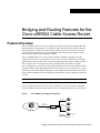
Bridging and Routing Features for the
Cisco uBR924 Cable Access Router
Feature Overview
The Cisco uBR924 cable access router is a fully-functional Cisco IOS router and standards-based
bidirectional cable modem that gives a residential or small office/home office (SOHO) subscriber
high-speed Internet or Intranet access and packet telephone services via a shared two-way cable
system and IP backbone network. The Cisco uBR924 is based on the current Data-Over-Cable
Service Interface Specifications (DOCSIS) standards.
The Cisco uBR924 cable access router connects computers, telephone equipment, and other
customer premises devices at a subscriber site to the service provider’s Hybrid/Fiber Coax (HFC)
and IP backbone network. Subscribers can access the Internet at speeds of up to 10 Mbps as well as
make telephone calls—all using the same cable system that delivers broadcast TV signals.
The Cisco uBR924 is a compact device that supports the direct connection of up to four PCs and has
the familiar features and programming interface of other routers in Cisco’s extensive line of smalland medium-sized business product offerings. The Cisco uBR924 provides packet data transport and
network address translation for TCP/IP applications between home or office computers and the cable
headend.
Note This document describes the features available in Cisco IOS Release 12.0(5)T.
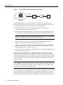
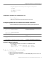
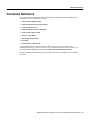
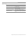
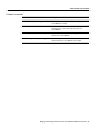
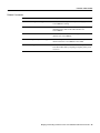
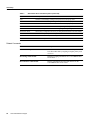
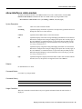
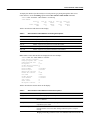
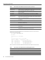
You can configure the cable access router to act as a bridge or as a router. See Figure 1 and Figure 2.
For more detailed descriptions of these options, see the “Configuration Options” section on page 3.
Figure 1
Cisco uBR924 in a Bridging Configuration
PC
Ethernet
CATV
coaxial cable
Cisco uBR7200 series
CMTS
Cisco uBR900 series
cable access router
PC
Ethernet
PC
Ethernet
HFC network
13305
PC or hub
Ethernet
Bridging and Routing Features for the Cisco uBR924 Cable Access Router 1
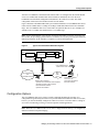
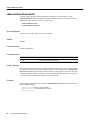
Feature Overview
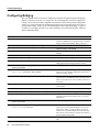
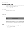
Cisco uBR924 in a Routing Configuration with a Hub
CATV
coaxial cable
Cable
Modem
Ethernet
Cisco uBR7246
CMTS
Ethernet
LAN
HUB
13306
Figure 2
HFC network
The Cisco uBR924 cable access router is referred to as a subscriber unit. The subscriber unit
functions as an interface between the subscriber’s customer premises equipment (CPE) devices at
the small office/home office and the cable operator’s network (the headend).
The Cisco uBR924 cable access router provides the following ports and connectors:
•
•
A single F-connector interface to the cable network.
Four RJ-45 (10BaseT Ethernet) hub ports to connect up to four computers directly to the cable
access router when configured for either routing mode or DOCSIS-compliant bridging mode.
Note When in routing mode, one of the four Ethernet ports can be connected to an Ethernet hub,
which then can connect additional computers or devices at the site.
•
Two RJ-11 ports to connect two or more telephones to the cable system and IP backbone to
support Voice over IP (VoIP) digitized voice transmission via H.323v2.
•
One RJ-11 port to connect to a standard, analog telephone line (optional) to provide a backup
Plain Old Telephone Service (POTS) connection to the Public Switched Telephone Network
(PSTN) should the cable access router lose power.
•
One RJ-45 console port to connect to an ASCII terminal or PC when locally troubleshooting or
reconfiguring the cable access router.
When supporting basic Internet access, the cable interface requires no configuration or setup
procedures other than to connect the Cisco uBR924 to the cable system. The unit is configured
automatically using a configuration file generated by the cable service provider and delivered via the
Cisco universal broadband router installed at the cable headend. The headend router provides a path
from the cable access router to the Dynamic Host Configuration Protocol (DHCP) server for PC
address assignment.
Note To support VoIP applications, a Cisco IOS image that supports voice must be downloaded to
the Cisco uBR924 in addition to the configuration file that is automatically downloaded at power-up.
For information on downloading IOS images to the Cisco uBR924, see the Cisco uBR924 Cable
Access Router Installation and Configuration Guide.
The PCs connected to the Cisco uBR924 cable access router must be configured for Internet Protocol
(IP). Using DHCP, the universal broadband router assigns an IP subnet address to the cable access
router each time it connects to the network. The IP addresses of the cable access router and the
individual PCs attached to it enable the universal broadband router to route data to and from the PCs.
2
Cisco IOS Release 12.0(5)T
Configuration Options
After the Cisco uBR924 is installed and the connected PCs are configured for IP, and after DHCP
services are enabled and communication to the headend is established, the Cisco universal
broadband router downloads configuration information to the cable access router. The initial
configuration connection to the headend can take several minutes.
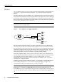
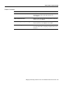
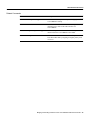
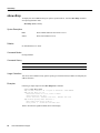
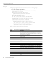
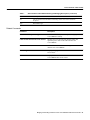
Figure 3 illustrates a broadband data cable system. Data transmitted to a Cisco uBR924 cable access
router from the CMTS shares a 27 Mbps or 26 Mbps, 6 MHz data channel in the 88 to 860 MHz
range. The Cisco uBR924 cable access router shares an upstream data rate of up to 10 Mbps on a
200 kHz-wide to 3.2 MHz-wide channel in the 5 to 42 MHz range.
Note End-to-end throughput varies based on the design and loading of network components, the
mix of traffic, the processing speed and interface of the host server(s), the processing speed and local
Ethernet performance of the subscriber’s computer, as well as other parameters.
Figure 3
Typical Cisco Broadband Data Cable System
WAN
Switch/router
CMTS
rack equipment
Combiner
Tx
Fiber
Rx
Servers
Internal backbone
and
worldwide internet
HFC
cable
plant
Cable System Headend
Upstream and downstream data interfaces
Operation support system interface
Downstream RF interface
Upstream RF interface
18197
Cisco uBR900 series
cable access router
Residence or SOHO
subscriber site:
subscriber RF interface
Ethernet interface
Configuration Options
The Cisco uBR924 cable access router is usually configured automatically at startup via a
configuration file generated by the cable service provider and downloaded to the cable access router;
however, you can also manually configure the cable access router to function either as a bridge or
as a router. The following sections give brief descriptions of both applications.
Note When the Cisco uBR924 cable access router is shipped from the factory, it is configured by
default for DOCSIS-compliant bridging.
Bridging and Routing Features for the Cisco uBR924 Cable Access Router 3
Feature Overview
Bridging
The Cisco uBR924 cable access router complies with the DOCSIS standards for interoperable cable
access routers; it supports full transparent bridging as well as DOCSIS-compliant transparent
bridging.
In bridging applications, the Cisco uBR924 acts as a transparent bridge for up to four PCs plugged
directly into the four Ethernet ports on the rear panel of the unit. The cable access router is connected
to the Internet via the coaxial cable. All four Ethernet ports are treated as one Ethernet interface by
the Cisco IOS software. The IP addresses for the PCs and the coaxial cable interface are typically in
the same subnet, although this is not a requirement.
Note If the attached PCs and the coaxial cable interface are in different IP subnets, the cable
interface must have a secondary address.
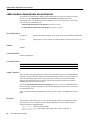
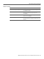
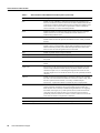
Figure 4
Cisco uBR924 in a Bridging Configuration
PC
Ethernet
CATV
coaxial cable
Cisco uBR7200 series
CMTS
Cisco uBR900 series
cable access router
PC
Ethernet
PC
Ethernet
HFC network
13305
PC or hub
Ethernet
DOCSIS-compliant transparent bridging is the default configuration of the Cisco uBR924 cable
access router. If your cable service provider is using a DHCP server, all you need to do is connect
the cables and power on the cable access router; your service provider’s configuration program will
automatically configure both the coaxial cable interface and the bridging functionality. You do not
need to set up IP addresses for the attached PCs or enter any Command Line Interface (CLI)
configuration commands. This type of operation is called plug-and-play bridging.
In DOCSIS-compliant bridging mode, the cable access router is able to locate a downstream and
upstream channel; find TOD, TFTP, and DHCP server(s); obtain an IP address; download a DOCSIS
configuration file; and obtain DHCP parameters to work in a bridging mode. For a better
understanding of the processes involved, refer to the online Cisco uBR924 Cable Access Router
Installation and Configuration Guide.
In addition to the plug-and-play method of operation, you can configure a bridging application on
the Cisco uBR924 using the CLI. See the sections “Configuring Bridging” on page 16 and
“Customizing the Cable Access Router Interface” on page 19 for details.
Note The ability of the cable access router to learn CPE MAC addresses in the DOCSIS-compliant
bridging mode is controlled by the MAC CPE option in the DOCSIS configuration file. The
Cisco uBR924 cable access router defaults to learning only one CPE MAC address unless this option
is set to 4. The maximum number of CPE MAC addresses that can be supported in bridging mode is
15.
4
Cisco IOS Release 12.0(5)T
Routing
Routing
The Cisco uBR924 cable access router can also be configured to act as a router to preserve IP address
space and limit broadcasts that can impact the performance of the network. A typical use would be
if you are connecting the cable access router to an internal Ethernet hub that is connected to an
existing PC network. You can also connect the cable access router directly to as many as four PCs
via the Ethernet ports on the rear panel.
The cable access router is automatically configured to use the IP address of the Cisco headend cable
router as the cable access router’s default IP gateway.
Cisco uBR924 in a Routing Configuration with a Hub
CATV
coaxial cable
Cisco uBR7246
CMTS
Cable
Modem
Ethernet
Ethernet
LAN
HUB
13306
Figure 5
HFC network
You can configure the Cisco uBR924 cable access router to function as a router by using one of the
following methods:
•
By using TFTP to download a configuration file from the headend router to the cable access
router that automatically configures it for routing.
•
By connecting an ASCII terminal or PC to the console port on the back of the cable access router
and using the CLI. See the sections “Configuring a Host Name and Password” on page 12 and
“Customizing the Cable Access Router Interface” on page 19 for details
Benefits
The Cisco uBR924 cable access router provides the following benefits for data-over-cable
applications:
•
Allows telecommuters and small office/home office customers to leverage the high-bandwidth,
low-cost, IP-based data and voice services offered by cable operators
•
Enables the cost-effective deployment of advanced routing capabilities to the small office or
home office site
•
Prioritizes voice traffic ahead of data traffic, ensuring quality of service (QoS) over a shared cable
infrastructure
•
Leverages Cisco’s industry-standard routing hardware and Cisco IOS software to deliver
advanced networking services and applications such as virtual private networks (VPNs), support
for multi-protocol networks, firewall security, and the ability to cost-effectively deploy local area
networks (LANs)
Bridging and Routing Features for the Cisco uBR924 Cable Access Router 5
Restrictions
Restrictions
When using the Cisco uBR924 cable access router, keep the following restrictions and limitations in
mind:
•
The Cisco uBR924 cable access router is able to implement multiples classes of service (CoS)
on the cable interface; however, separate CoS streams are only available when the cable access
router is connected to a headend that supports multiple classes of service per cable access router.
In addition, the configuration file downloaded to the cable access router must specify the use of
multiple classes of service.
•
If the Cisco uBR924 cable access router is connected to a DOCSIS 1.0 headend that does not
support multiple CoS per cable access router, voice and data will be mixed, and voice traffic will
be transmitted on a best effort basis. This may cause poorer voice quality and lower data
throughput when calls are being made from the cable access router’s telephone ports. Voice
quality is also affected when transmitting or downloading large files, as well as by other
significant network traffic.
Note The Cisco uBR924 cable access router is typically configured at the headend. Most subscriber
sites do not permit local configuration. Remote configuration is either disabled or routinely reset to
settings in the provisioning or billing systems.
Caution Before attempting to reconfigure a Cisco uBR924 cable access router at a subscriber site, contact
your network management, provisioning manager, or billing system administrator to ensure remote
configuration is allowed. If remote configuration is disabled, settings you make and save at the local site will
not remain in effect after the cable access router is powered off and back on. Instead, settings will return to
the previous configuration.
Related Features and Technologies
The Cisco uBR924 cable access router is intended to be used in conjunction with a Cisco uBR7246
or a Cisco uBR7223 universal broadband router located at the cable operator’s headend facility.
Other compatible headend devices may also be used with the Cisco uBR924.
Related Documents
For related information on the Cisco uBR924 cable access router, refer to the following documents:
•
•
•
•
•
•
•
•
•
•
6
Cisco uBR924 Cable Access Router Quick Start Guide
Cisco uBR924 Cable Access Router Installation and Configuration Guide
Regulatory Compliance and Safety Info. for the Cisco uBR924 Cable Access Router
Cisco uBR7246 Installation and Configuration Guide
Cisco uBR7223 Installation and Configuration Guide
Cisco uBR7200 Series Configuration Notes
Cisco Network Registrar for the uBR7200 Series
Regulatory and Safety Compliance for the Cisco uBR7246
Regulatory and Safety Compliance for the Cisco uBR7223
Cisco uBR7200 Series Universal Broadband Router Features
Cisco IOS Release 12.0(5)T
Supported Platforms
Supported Platforms
The Cisco uBR924 cable access router is a standalone device; it works in conjunction with the
Cisco uBR7246 and the Cisco uBR7223 universal broadband routers.
Prerequisites
In order to use the Cisco uBR924 cable access router for data-over-cable applications, the following
tasks must be completed:
•
All required CMTS routers, servers (DHCP, TFTP and TOD), network management systems,
and/or other configuration or billing systems to be used in your network must be installed,
configured, and operational. If you are using a Cisco uBR7246 or uBR7223 universal broadband
router at the cable headend, refer to the Cisco uBR7246 Installation and Configuration Guide or
the Cisco uBR7223 Installation and Configuration Guide for detailed information.
•
Based on the quality and capacity of your cable plant, your system administrator or network
planner must define your network’s IP address allocation plan; spectrum management plan
outlining the recommended operating parameters to optimize performance; channel plan
identifying the channels available to assign to specific Cisco uBR924 cable access routers; and
dial plan based on the supported VoIP protocol.
•
The CMTS system administrator or appropriate personnel must specify the policy parameters for
the Cisco uBR924 and all computers and other customer premises devices to be supported at
subscriber sites. Refer to Cisco’s Network Registrar (CNR) product documentation.
•
The CMTS system administrator or appropriate personnel must define and push DHCP and
Cisco uBR924 configuration files to the appropriate servers such that each router, when
initialized, can transmit a DHCP request, receive its IP address, obtain its TFTP and TOD server
addresses, and download its configuration file or updated Cisco IOS image.
Note The MAC address ensures that each router downloads only the file(s) intended for it.
•
The Cisco uBR924 cable access router must be physically installed and cabled as follows:
— To the headend via CATV coaxial cable. (High-quality, shielded RF coaxial cable with at
least 80% braid is recommended.)
— To at least one PC via the straight-through yellow Ethernet cable supplied with the cable
access router. Refer to the Cisco uBR924 Cable Access Router Quick Start Guide for detailed
information.
Note When the Cisco uBR924 is connected to an Ethernet hub, a crossover cable must be used.
Category 5 UTP (10BaseT Ethernet) cable with RJ-45 connectors is recommended.
Note For subscriber sites that support multiple telephones or fax devices on a telephone line, all
wiring associated with the telephone line extension must be in place. Inside wiring must be in
compliance with the country of operation to prevent degradation of service.
Bridging and Routing Features for the Cisco uBR924 Cable Access Router 7
Supported MIBs and RFCs
•
The CMTS system administrator must ensure appropriate databases are updated to activate and
support the new subscriber account in the provisioning, billing and/or network management
systems in place for your network once each router is registered with the CMTS.
•
•
The PC(s) connected to the Cisco uBR924 cable access router must be configured for IP.
Cisco IOS Release 11.3(4)NA or later must be running on the Cisco uBR924 cable access router.
When the cable access router is up and running, you can display the IOS release number by
entering the show version command from user EXEC mode.
Note If the Cisco uBR7246 universal broadband router at the cable headend is using MC16 modem
cards, Cisco IOS Release 11.3(7)NA or later must be running on the Cisco uBR924 cable access
router.
In order to use the Cisco uBR924 cable access router for VoIP-over-cable applications, the following
additional conditions must be met:
•
In order to run VoIP Fax, the uBR924 cable access router must be configured for voice and you
must be using Cisco IOS Release 12.0(5)T or higher.
Supported MIBs and RFCs
The Cisco uBR924 cable access router supports the following:
•
Cisco Standard MIBs:
— Cisco Product MIB
— Cisco Chassis MIB
— Cisco Syslog MIB
— Cisco Flash MIB
— Bridge MIB
— IF MIB
— MIB-II
•
Cisco VoIP MIBs:
— Cisco Voice IF MIB
— Cisco Voice Dial-Control MIB
— Cisco Voice Analog IF MIB
— Cisco Dial-Control MIB
•
Radio Frequency Interface Specification—Developed by the Multimedia Cable Network System
(MCNS) consortium. It defines the radio-frequency interface specification for high-speed
data-over-cable systems.
•
CiscoWorks—Network management program for planning, troubleshooting, and monitoring
Cisco internetworks. CiscoWorks uses Simple Network Management Protocol (SNMP) to
monitor all SNMP devices.
— For more information about CiscoWorks on CCO, follow this path:
Products & Ordering: Cisco Products: Network Management: CiscoWorks
8
Cisco IOS Release 12.0(5)T
List of Terms and Acronyms
— For more information about CiscoWorks on the Documentation CD-ROM, follow this path:
Cisco Product Documentation: Network Management: CiscoWorks
•
Radio Frequency Interface (RFI) MIB—Specific to Data-Over-Cable Service Interface
Specification (DOCSIS) cable implementations. The RIF MIB provides an interface that permits
management of the Cisco uBR924 cable access router over the cable or Ethernet interface. Using
SNMP management applications, this MIB allows access to statistics such as MAC, driver
configuration, and counters.
•
Cable Device MIB—Records statistics related to the configuration and status of the
Cisco uBR924 cable access router. Statistics include an events log and device status. The Cable
Device MIB is very similar to the RFI MIB in that both allow access to statistics; they are
different in that the Cable Device MIB reports statistics on the cable access router, while the RFI
MIB reports statistics on the radio frequency transmissions over the cable television line.
For descriptions of supported MIBs and how to use MIBs, see Cisco’s MIB web site on CCO at
http://www.cisco.com/public/sw-center/netmgmt/cmtk/mibs.shtml.
List of Terms and Acronyms
broadband—Transmission system that combines multiple independent signals onto one cable. In
the cable industry, broadband refers to the frequency-division multiplexing of many signals in a wide
bandwidth of RF frequencies using a hybrid fiber-coaxial (HFC) network.
CATV—Originally stood for Community Antenna Television. Now refers to any coaxial or fiber
cable-based system that provides television services.
cable modem (CM)—A modulator-demodulator device that is placed at subscriber locations to
convey data communications on a cable television system. The Cisco uBR924 cable access router is
also a cable modem.
Cable Modem Termination System (CMTS)—A termination system located at the cable
television system headend or distribution hub which provides complementary functionality to the
cable modems, enabling data connectivity to a wide-are network.
cable router—A modular chassis-based router optimized for data-over-CATV hybrid fiber-coaxial
(HFC) applications.
carrier—A signal on which another, lower-frequency signal is modulated in order to transport the
lower-frequency signal to another location.
Carrier-to-Noise—C/N (also CNR). The difference in amplitude between the desired RF carrier
and the noise in a portion of the spectrum.
channel—A specific frequency allocation and bandwidth. Downstream channels used for television
are 6 MHz wide in the United States; 8 MHz wide in Europe.
CM—cable modem.
CMTS—Cable Modem Termination System.
coaxial cable—The principal physical media over which CATV systems are built.
CPE—Customer Premises Equipment
dB—Decibel. A measure of the relative strength of two signals.
dBm—Decibels with respect to one milliwatt. A unit of RF signal strength used in satellite work and
other communications applications.
Bridging and Routing Features for the Cisco uBR924 Cable Access Router 9
List of Terms and Acronyms
dBmV—Decibels with respect to one millivolt in a 75-ohm system. The unit of RF power used in
CATV work in North America.
DHCP—Dynamic Host Configuration Protocol. This protocol provides a mechanism for allocating
IP addresses dynamically so that addresses can be reused when hosts no longer need them.
DOCSIS—Data Over Cable Service Interface Specification. Defines technical specifications for
equipment at both subscriber locations and cable operators’ headends.
downstream—The set of frequencies used to send data from a headend to a subscriber.
FDM—Frequency Division Multiplexing. A data transmission method in which a number of
transmitters share a transmission medium, each occupying a different frequency.
FEC—Forward Error Correction. In data transmission, a process by which additional data is added
that is derived from the payload by an assigned algorithm. It allows the receiver to determine if
certain classes of errors have occurred in transmission and, in some cases, allows other classes of
errors to be corrected.
headend—Central distribution point for a CATV system. Video signals are received here from
satellite (either co-located or remote), frequency converted to the appropriate channels, combined
with locally originated signals, and rebroadcast onto the HFC plant. For a CATV data system, the
headend is the typical place to create a link between the HFC system and any external data networks.
HFC—Hybrid fiber-coaxial (cable network). Older CATV systems were provisioned using only
coaxial cable. Modern systems use fiber transport from the headend to an optical node located in the
neighborhood to reduce system noise. Coaxial cable runs from the node to the subscriber. The fiber
plant is generally a star configuration with all optical node fibers terminating at a headend. The
coaxial cable part of the system is generally a trunk-and-branch configuration.
host—Any end-user computer system that connects to a network. In this document, the term host
refers to the computer system connected to the LAN interface of the cable access router.
ingress noise—Over-the-air signals that are inadvertently coupled into the nominally closed coaxial
cable distribution system. Ingress noise is difficult to track down and intermittent in nature.
MAC layer—Media Access Control sublayer. Controls access by the cable access router to the
CMTS and to the upstream data slots.
MCNS—Multimedia Cable Network System Partners Ltd. A consortium of cable companies
providing service to the majority of homes in the United States and Canada. This consortium has
decided to drive a standard with the goal of having interoperable cable access routers.
MSO—Multiple System Operator. A cable service provider that operates in more than one
geographic area, thus having multiple headend facilities.
narrowband—A single RF frequency.
NTSC—National Television Systems Committee. A United States TV technical standard, named
after the organization that created the standard in 1941. Specifies a 6 MHz-wide modulated signal.
PAL—Phase Alternating Line. The TV system used in most of Europe, in which the color carrier
phase definition changes in alternate scan lines. Utilizes an 8 MHz-wide modulated signal.
QAM—Quadrature Amplitude Modulation. A method of modulating digital signals onto a
radio-frequency carrier signal in which the value of a symbol consisting of multiple bits is
represented by amplitude and phase states of the carrier. QAM is a modulation scheme mostly used
in the downstream direction (64-QAM, 256-QAM). 16-QAM is expected to be usable in the
upstream direction. Numbers indicate number of code points per symbol. The QAM rate or the
number of points in the QAM constellation can be computed by 2 raised to the power of <number
of bits/symbol>. For example, 16-QAM has 4 bits per symbol, 64-QAM has 6 bits per symbol, and
256-QAM has 8 bits per symbol.
10
Cisco IOS Release 12.0(5)T
Configuration Tasks
QPSK—Quadrature Phase-Shift Keying. A digital modulation method in which there are 2 data bits
represented with each baud symbol.
ranging—The process of acquiring the correct timing offset such that the transmissions of a cable
access router are aligned with the correct mini-slot boundary.
RF—Radio frequency. The portion of the electromagnetic frequency spectrum from 5 MHz to
approximately 860 MHz.
SECAM—TV system used in France and elsewhere, utilizing an 8 MHz-wide modulated signal.
SID (Service ID)—A number that defines (at the MAC sublayer) a particular mapping between a
cable access router (CM) and the CMTS. The SID is used for the purpose of upstream bandwidth
allocation and class-of-service management.
Signal-to-Noise—S/N (also SNR). The difference in amplitude between a baseband signal and the
noise in a portion of the spectrum.
spectrum reuse—CATV’s most fundamental concept. Historically, the over-the-air spectrum has
been assigned to many purposes other than that of carrying TV signals. This has resulted in an
inadequate supply of spectrum to serve the needs of viewers. Cable can reuse spectrum that is sealed
in its aluminum tubes.
subscriber unit (SU)—An alternate term for cable access router. See cable access router.
upstream—The set of frequencies used to send data from a subscriber to the headend.
Configuration Tasks
The Cisco uBR924 cable access router typically is configured automatically on power-up using a
configuration file generated by the cable service provider and delivered via the Cisco uBR7246 or
the Cisco uBR7223 universal broadband router installed at the cable headend. All of the
configuration tasks listed below are optional.
•
•
•
•
•
•
Configuring a Host Name and Password on page 12
Configuring Ethernet and Cable Access Router Interfaces on page 13
Configuring Routing on page 14
Configuring Bridging on page 16
Reestablishing DOCSIS-Compliant Bridging on page 18
Customizing the Cable Access Router Interface on page 19
Caution Before attempting to reconfigure a Cisco uBR924 cable access router at a subscriber site, contact
your network management, provisioning manager, or billing system administrator to ensure remote
configuration is allowed. If remote configuration is disabled, settings you make and save at the local site will
not remain in effect after the cable access router is powered off and back on. Instead, settings will return to
the previous configuration.
Note Console sessions and TTY sessions are supported by the cable access router.
Bridging and Routing Features for the Cisco uBR924 Cable Access Router 11
Configuring a Host Name and Password
Configuring a Host Name and Password
One of the first configuration tasks you might want to perform is to configure a host name and set an
encrypted password. Configuring a host name allows you to distinguish multiple Cisco uBR924
cable access routers from each other. Setting an encrypted password allows you to prevent
unauthorized configuration changes.
Note Passwords are case sensitive.
To configure a host name and an encrypted password for a Cisco uBR924 cable access router,
perform the following tasks, starting in global configuration mode:
Step
Command
Purpose
1
uBR924(config)# hostname cisco
cisco(config)#
Change the name of the uBR924 to a meaningful name.
Substitute your host name for cisco.
2
cisco(config)# enable secret guessme
Enter an enable secret password. This password provides
access to enable (privileged EXEC) mode.
After configuring a password, when you enter enable at
the EXEC prompt, you must enter the enable secret
password to gain access to configuration mode. Substitute
your enable secret password for guessme.
3
cisco(config)# line console 0
cisco(config-line)# exec-timeout 0 0
cisco(config-line)# exit
cisco(config)#
Enter line configuration mode to configure the console
port.
Prevent the EXEC facility from timing out if you do not
type any information on the console screen for an
extended period.
Exit back to global configuration mode.
Verifying the Host Name and Password
To verify that you configured the correct host name and password, enter the show running-config
command from global configuration mode:
cisco(config)# show running-config
Using 1888 out of 126968 bytes
!
version XX.X
.
.
!
hostname cisco
!
enable secret 5 $1$60L4$X2JYOwoDc0.kqa1loO/w8/
•
12
Check the host name and encrypted password displayed near the top of the command output.
Cisco IOS Release 12.0(5)T
Configuration, Verification, and Troubleshooting Tips
•
Exit global configuration mode and attempt to reenter it using the new enable password:
cisco# exit
cisco con0 is now available
Press RETURN to get started.
cisco> enable
Password: guessme
cisco#
Configuration, Verification, and Troubleshooting Tips
If you are having trouble:
•
•
Make sure Caps Lock is off.
Make sure you entered the correct passwords. Passwords are case sensitive.
Configuring Ethernet and Cable Access Router Interfaces
To assign an IP address to the Ethernet or cable access router interface so that it can be recognized
as a device on the Ethernet LAN, perform the following tasks, starting in global configuration mode:
Step
Command
Purpose
1
uBR924(config)# interface ethernet 0
Enter interface configuration mode for the Ethernet and/or
the cable access router interface.
or
uBR924(config)# interface modem-cable0
uBR924(config-if)#
2
uBR924(config-if)# ip address 172.16.1.1 255.255.255.0
Assign the appropriate IP address and subnet mask to the
interface.
3
uBR924(config-if)# Ctrl-Z
uBR924#
Return to privileged EXEC mode.
%SYS-5-CONFIG_I: Configured from console by console
This message is normal and does not indicate an error.
Verifying IP Address Configuration
To verify that you have assigned the correct IP address, enter the show arp command:
uBR924# show arp
Protocol Address
Internet 172.16.1.1
Internet 4.0.0.28
Age (min)
-
Hardware Addr
0009.0613.6030
00e0.1ed7.524d
Type
ARPA
ARPA
Interface
cable-modem0
Ethernet0
Configuration, Verification, and Troubleshooting Tips
If you are having trouble:
•
•
Make sure you are using the correct IP address.
Make sure the cable interface is not shut down. Use the show running-config command to check the cable
interface status.
Bridging and Routing Features for the Cisco uBR924 Cable Access Router 13
Configuring Routing
Configuring Routing
DOCSIS-compliant transparent bridging is the factory default configuration of the Cisco uBR924
cable access router. To change the configuration of your cable access router from bridging to routing
using the CLI, perform the following tasks, starting in global configuration mode:
Step
Command
Purpose
1
uBR924(config)#interface cable-modem0
Enter interface configuration mode for the cable access
router interface.
2
uBR924(config-if)#no cable-modem compliant bridge
Turn off DOCSIS-compliant bridging.
uBR924(config-if)#no bridge-group 59
Remove the default bridge group assignment from the
cable interface.
uBR924(config-if)#end
Return to global configuration mode.
uBR924(config)#ip routing
Enable IP routing for the cable access router.
uBR924(config)#ip subnet-zero
Enable the use of subnet zero for interface addresses and
routing updates.
uBR924(config)#ip route <IP address of CMTS> <subnet
mask of CMTS>
Create a static route to the CMTS to make sure that Time
of Day (TOD) packets are properly routed out of the cable
access router.
4
uBR924(config)#router rip
Enter router configuration mode and enable Routing
Information Protocol (RIP) on the cable access router.
5
uBR924(config-router)#network network-number
Specify the network connected to the cable access router
on which the RIP process will operate. If the cable access
router is attached to more than one network, enter each IP
address in a separate command.
6
uBR924(config-router)#end
Exit router configuration mode.
Return to interface configuration mode for the cable
access router interface.
3
uBR924(config)#interface cable-modem0
7
uBR924(config-if)#ip rip receive v 2
Specify that only RIP Version 2 packets will be received
on the coaxial cable interface.
8
uBR924(config-if)#ip rip send v 2
Specify that only RIP Version 2 packets will be sent on
the coaxial cable interface.
9
uBR924(config-if)#end
Exit interface configuration mode for the cable access
router interface and enter interface configuration mode for
the Ethernet0 interface.
uBR924(config)#interface ethernet0
10
uBR924(config-if)#no bridge-group 59
Remove the default bridge group assignment from the
Ethernet0 interface.
11
uBR924(config-if)#ip rip receive v 2
Specify that only RIP Version 2 packets will be received
on this Ethernet interface.
12
uBR924(config-if)#ip rip send v 2
Specify that only RIP Version 2 packets will be sent on
this Ethernet interface.
13
uBR924(config-if)#Ctrl-z
Return to privileged EXEC mode.
Save the configuration to nonvolatile RAM so that it
won’t be lost in the event of a reset, power cycle, or power
outage.
uBR924#copy running-config startup-config
Building configuration...
14
Cisco IOS Release 12.0(5)T
Verifying Routing
Verifying Routing
To verify that bridging is not configured, routing is enabled, and that Routing Information Protocol
is configured on the interfaces, enter the show startup-config command:
uBR924# show startup-config
Building configuration...
Current configuration:
!
version 12.0
no service pad
no service password-encryption
service udp-small-servers
service tcp-small-servers
!
hostname uBR924
!
!
clock timezone - 4
ip subnet-zero
!
!
!
voice-port 0
!
voice-port 1
!
!
interface Ethernet0
ip address 10.1.0.33 255.255.0.0
no ip directed-broadcast
ip rip send version 2
ip rip receive version 2
no keepalive
!
interface cable-modem0
ip address 172.16.1.42 255.255.0.0
no ip directed-broadcast
ip rip send version 2
ip rip receive version 2
no keepalive
cable-modem downstream saved channel 699000000 39
no cable-modem compliant bridge
!
router rip
network 4.0.0.0
network 172.16.0.0
!
ip classless
no ip http server
!
line con 0
transport input none
line vty 0 4
!
end
Bridging and Routing Features for the Cisco uBR924 Cable Access Router 15
Configuring Bridging
Configuring Bridging
The Cisco uBR924 cable access router is configured for DOCSIS-compliant transparent bridging by
default. If it becomes necessary to reconfigure the unit for bridging after it has been configured for
routing, you can erase the routing configuration and return the unit to factory default configuration
settings, or you can reconfigure the unit manually using the CLI. To return the cable access router to
factory default settings, see the section “Reestablishing DOCSIS-Compliant Bridging” on page 18
for details. To reconfigure the cable access router manually, perform the following tasks, starting in
global configuration mode:
Step
Command
Purpose
1
uBR924(config)#no service pad
Disable packet assembler/disassembler commands;
prevent the uBR924 from accepting incoming or outgoing
Packet Assembler/Disassembler (PAD) connections.
2
uBR924(config)#no service password-encryption
Disable password encryption.
3
uBR924(config)#no ip routing
Disable IP routing on the uBR924.
4
uBR924(config)#interface Ethernet0
Enter interface configuration mode for the Ethernet0
interface.
5
uBR924(config-if)#no ip address
Disable the IP address on the Ethernet0 interface.
6
uBR924(config-if)#no ip route-cache
Disable high-speed switching caches for IP routing.
7
uBR924(config-if)#bridge-group bridge-group
Assign the Ethernet0 interface to a bridge group. The
bridge group must be an integer between 1 and 63.
8
uBR924(config-if)#bridge-group bridge-group
spanning-disabled
Disable spanning tree on the Ethernet interface.
9
uBR924(config-if)#end
Exit interface configuration mode for the Ethernet0
interface and enter interface configuration mode for the
cable access router interface.
uBR924(config)#interface cable-modem0
10
uBR924(config-if)#no ip address
Disable the IP address of the coaxial cable interface, if
one has been set. The uBR7246 cable router assigns an IP
address to the cable access router each time it connects to
the network.
11
uBR924(config-if)#no ip route-cache
Disable high-speed switching caches for IP routing on the
cable interface.
12
uBR924(config-if)#no keepalive
Disable keepalives on the cable interface.
13
uBR924(config-if)#cable-modem compliant bridge
Enable DOCSIS-compliant bridging.
14
uBR924(config-if)#bridge-group bridge-group
Assign the cable access router interface to a bridge group.
The bridge group must be an integer from 1 to 63. (The
default is 59.)
15
uBR924(config-if)#bridge-group bridge-group
spanning-disabled
Disable spanning tree on the cable interface.
16
uBR924(config-if)#end
Exit interface configuration mode.
uBR924(config)#ip classless
(Optional) At times, the uBR924 might receive packets
destined for a subnet of a network that has no network
default route. This global configuration mode command
allows the Cisco IOS software to forward such packets to
the best network route possible.
17
uBR924(config)#line console 0
Enter line configuration mode to configure the console
port.
16
Cisco IOS Release 12.0(5)T
Verifying Bridging
Step
Command
Purpose
18
uBR924(config-line)#line vty 0 4
Identify the last line in a contiguous group of virtual
terminals you want to configure.
19
uBR924(config-line)#Ctrl-z
Return to privileged EXEC mode.
Save the configuration to nonvolatile RAM so that it
won’t be lost in the event of a reset, power cycle, or power
outage.
uBR924#copy running-config startup-config
Building configuration...
When the cable interface comes up, the IP address and downstream channel are configured
automatically.
Note To configure multiple PCs, repeat Steps 4 through 7 above for each additional PC. You can
connect a maximum of three PCs to the Cisco uBR924 cable access router in a bridging application.
Verifying Bridging
To verify that routing has been disabled on all interfaces and that bridging has been reenabled, enter the show
startup-config command from privileged EXEC mode:
uBR924# show startup-config
Building configuration...
Current configuration:
!
version 12.0
service config
no service pad
service timestamps debug uptime
service timestamps log uptime
no service password-encryption
!
hostname uBR924
!
clock timezone - 4
ip subnet-zero
no ip routing
!
!
voice-port 0
!
!
voice-port 1
!
!
interface Ethernet0
no ip address
no ip directed-broadcast
no ip route-cache
bridge-group 59
bridge-group 59 spanning-disabled
!
Bridging and Routing Features for the Cisco uBR924 Cable Access Router 17
Reestablishing DOCSIS-Compliant Bridging
interface cable-modem0
no ip address
no ip directed-broadcast
no ip route-cache
no keepalive
cable-modem downstream saved channel 699000000 36
bridge-group 59
bridge-group 59 spanning-disabled
!
ip classless
!
line con 0
line vty 0 4
login
!
end
Reestablishing DOCSIS-Compliant Bridging
To erase the current non-default cable access router configuration and return the unit to its factory
default DOCSIS-compliant bridging configuration, perform the following task from privileged
EXEC mode:
Step
Command
Purpose
1
uBR924#erase startup config
Erase the current configuration (assuming the current
running configuration has been saved to NVRAM).
After entering this command, perform a warm reset of the Cisco uBR924 cable access router by
pressing and holding down the Reset button for less than 10 seconds. For information on the location
and operation of the Reset button, refer to the “Physical Description” section in the chapter
“Installing the Cisco uBR924 Cable Access Router” in the Cisco uBR924 Cable Access Router
Installation and Configuration Guide.
Verifying DOCSIS-Compliant Bridging
To verify that the cable access router is configured for DOCSIS-compliant bridging, enter the show
startup-config command from privileged EXEC mode. The configuration should look like this:
uBR924# show startup-config
Building configuration...
Current configuration:
!
version 12.0
service config
no service pad
service timestamps debug uptime
service timestamps log uptime
no service password-encryption
!
hostname uBR924
!
clock timezone - 4
ip subnet-zero
no ip routing
!
!
!
18
Cisco IOS Release 12.0(5)T
Customizing the Cable Access Router Interface
voice-port 0
!
!
voice-port 1
!
!
interface Ethernet0
no ip address
no ip directed-broadcast
no ip route-cache
bridge-group 59
bridge-group 59 spanning-disabled
!
interface cable-modem0
no ip address
no ip directed-broadcast
no ip route-cache
no keepalive
cable-modem downstream saved channel 699000000 36
bridge-group 59
bridge-group 59 spanning-disabled
!
ip classless
no ip http server
!
line con 0
transport input none
line vty 0 4
login
!
end
Customizing the Cable Access Router Interface
Different geographical regions and different cable plants use different frequency bands. The
Cisco uBR924 cable access router uses a built-in default frequency scanning feature to address this
issue. After the cable access router finds a successful downstream frequency channel, it saves the
channel and power setting to NVRAM. The cable access router recalls this value the next time it
needs to synchronize its frequency or register with the cable service provider’s CMTS.
However, you can customize the cable access router’s interface configuration if you need to deviate
from the default setting that ships with the unit. For example, you might need to specify a different
compliant mode, modify the saved downstream channel setting and upstream power value, or enable
a faster downstream search algorithm.
Note Most cable network scenarios will not require you to use these commands.
To customize the cable access router interface, perform the following tasks, starting in global
configuration mode:
Step
Command
Purpose
1
uBR924(config)#interface cable-modem 0
Specify cable access router interface 0.
2
uBR924(config-if)#cable-modem compliant bridge
Enable DOCSIS-compliant bridging.
Bridging and Routing Features for the Cisco uBR924 Cable Access Router 19
Configuration Examples
Step
Command
Purpose
3
uBR924(config-if)#cable-modem downstream saved channel
ds-frequency us-power
Modify the saved downstream channel setting and
upstream power value. If you do this, you must specify an
exact downstream frequency and a power value.1
4
uBR924(config-if)#cable-modem fast-search
Enable a faster downstream search algorithm.
1Use the no cable-modem downstream saved channel ds-frequency us-power command to remove a saved frequency and power setting from NVRAM.
Configuration Examples
This section provides the following configuration examples:
•
•
•
•
•
Basic Internet Access Bridging Configuration on page 20
Basic Internet Access Routing Configuration on page 21
Multicast-Enabled Routing Configuration on page 22
VoIP Bridging Configuration Using H.323v2 on page 23
VoIP Routing Configuration Using H.323v2 on page 24
Basic Internet Access Bridging Configuration
The following Cisco uBR924 cable access router configuration supports a typical residential
Internet-access, data only subscriber:
Current configuration:
!
version 12.0
service config
no service pad
service timestamps debug uptime
service timestamps log uptime
no service password-encryption
!
hostname uBR924
!
clock timezone - 4
ip subnet-zero
no ip routing
!
!
voice-port 0
!
!
voice-port 1
!
!
interface Ethernet0
ip address 172.16.1.40 255.255.0.0
no ip directed-broadcast
no ip route-cache
bridge-group 59
bridge-group 59 spanning-disabled
!
20
Cisco IOS Release 12.0(5)T
Basic Internet Access Routing Configuration
interface cable-modem0
ip address 172.16.1.40 255.255.0.0
no ip directed-broadcast
no ip route-cache
cable-modem downstream saved channel 699000000 36
bridge-group 59
bridge-group 59 spanning-disabled
!
ip classless
no ip http server
!
line con 0
transport input none
line vty 0 4
login
!
end
Basic Internet Access Routing Configuration
The Cisco uBR924 cable access router can be configured to act as a router to preserve IP address
space and limit broadcasts that can impact the performance of the network. A sample configuration
file follows.
Note To configure the Cisco uBR924 to act as a router, the no cable-modem compliant bridge
command must be used. In addition, the bridge group 59 command must be removed from the
Ethernet and cable-modem interfaces.
Current configuration:
!
version 12.0
service config
no service pad
service timestamps debug uptime
service timestamps log uptime
no service password-encryption
!
hostname uBR924
!
!
clock timezone - 4
ip subnet-zero
!
!
!
voice-port 0
!
voice-port 1
!
!
interface Ethernet0
ip address 10.1.0.33 255.255.0.0
no ip directed-broadcast
!
Bridging and Routing Features for the Cisco uBR924 Cable Access Router 21
Configuration Examples
interface cable-modem0
ip address 172.16.1.42 255.255.0.0
no ip directed-broadcast
cable-modem downstream saved channel 699000000 39
no cable-modem compliant bridge
!
router rip
network 4.0.0.0
network 172.16.0.0
!
ip classless
no ip http server
!
line con 0
transport input none
line vty 0 4
!
end
Multicast-Enabled Routing Configuration
The following configuration is for a Cisco uBR924 that uses PIM sparse-dense mode and belongs to
a specific multicast group. Other multicast routing protocols such as PIM sparse-mode or PIM
dense-mode can be used.
Current configuration:
!
! Last configuration change at 23:16:44 - Thu Mar 18 1999
!
version 12.0
service config
no service pad
service timestamps debug uptime
service timestamps log uptime
no service password-encryption
!
hostname uBR924
!
!
clock timezone - 4
ip subnet-zero
!
!
ip multicast-routing
ip dvmrp route-limit 20000
!
!
voice-port 0
!
voice-port 1
!
!
interface Ethernet0
ip address 24.1.0.1 255.255.0.0
no ip directed-broadcast
ip pim sparse-dense-mode
no ip route-cache
no ip mroute-cache
!
22
Cisco IOS Release 12.0(5)T
VoIP Bridging Configuration Using H.323v2
interface cable-modem0
ip address 10.1.0.25 255.255.0.0
no ip directed-broadcast
ip pim sparse-dense-mode
no ip route-cache
no ip mroute-cache
cable-modem downstream saved channel 477000000 56
no cable-modem compliant bridge
!
!
router rip
version 2
network 24.0.0.0
network 10.0.0.0
!
!
ip classless
no ip http server
!
!
line con 0
transport input none
line vty 0 4
!
end
VoIP Bridging Configuration Using H.323v2
In this example, the Cisco uBR924 is configured for bridging, with an H.323v2 dial peer to another
Cisco uBR924 attached to the same downstream interface on the headend CMTS.
Current configuration:
!
! Last configuration change at 21:54:41 - Thu Apr 29 1999
! NVRAM config last updated at 21:56:20 - Thu Apr 29 1999
!
version 12.0
no service pad
service timestamps debug uptime
service timestamps log uptime
no service password-encryption
!
hostname 2007
!
!
clock timezone - 3
ip subnet-zero
no ip routing
!
!
voice-port 0
input gain -3
!
voice-port 1
input gain -3
!
dial-peer voice 1 pots
destination-pattern 6501
port 0
!
Bridging and Routing Features for the Cisco uBR924 Cable Access Router 23
Configuration Examples
dial-peer voice 2 pots
destination-pattern 6502
port 1
!
dial-peer voice 62 voip
destination-pattern 620.
session target ipv4:10.1.71.62
!
!
interface Ethernet0
ip address 10.1.71.65 255.255.255.0
no ip directed-broadcast
no ip route-cache
bridge-group 59
bridge-group 59 spanning-disabled
!
interface cable-modem0
description DHCP Reserved Address 10.1.71.65
ip address 10.1.71.65 255.255.255.0
no ip directed-broadcast
no ip route-cache
cable-modem downstream saved channel 537000000 27
bridge-group 59
bridge-group 59 spanning-disabled
!
ip classless
no ip http server
!
!
line con 0
exec-timeout 0 0
transport input none
line vty 0 4
login
!
!
end
VoIP Routing Configuration Using H.323v2
In this example, the Cisco uBR924 is configured for IP routing, with an H.323v2 dial peer to another
Cisco uBR924 attached to the same downstream interface on the headend CMTS.
Current configuration:
!
! No configuration change since last restart
!
version 12.0
no service pad
service timestamps debug uptime
service timestamps log uptime
no service password-encryption
!
hostname 2007
!
!
class-map class-default
match any
!
!
clock timezone - 3
ip subnet-zero
!
!
24
Cisco IOS Release 12.0(5)T
VoIP Routing Configuration Using H.323v2
voice-port 0
!
voice-port 1
!
dial-peer voice 1 pots
destination-pattern 6101
port 0
!
dial-peer voice 2 pots
destination-pattern 6102
port 1
!
dial-peer voice 101 voip
destination-pattern 620*
codec g711alaw
session target ipv4:10.1.71.62
!
!
interface Ethernet0
ip address 24.1.61.1 255.255.255.0
no ip directed-broadcast
no ip mroute-cache
!
interface cable-modem0
ip address 10.1.71.61 255.255.255.0
no ip directed-broadcast
no ip mroute-cache
cable-modem downstream saved channel 537000000 27
no cable-modem compliant bridge
!
router rip
version 2
network 10.0.0.0
network 24.0.0.0
no auto-summary <<==== Not necessary
!
no ip classless
ip route 0.0.0.0 0.0.0.0 10.1.71.1
no ip http server
!
!
line con 0
exec-timeout 0 0
transport input none
line vty 0 4
login
!
!
end
Bridging and Routing Features for the Cisco uBR924 Cable Access Router 25
Configuration Examples
NAT/PAT Configuration
Current configuration:
!
! No configuration change since last restart
!
version 12.0
no service pad
service timestamps debug uptime
service timestamps log uptime
no service password-encryption
!
hostname uBR924
!
!
ip nat inside source list 1 interface cable-modem0 overload
clock timezone - -4
!
!
interface Ethernet0
ip address 10.1.1.1 255.255.255.0
ip nat inside
!
interface cable-modem0
ip address 24.3.90.20 255.255.255.0
ip nat outside
no keepalive
cable-modem downstream saved channel 627000000 54
no cable-modem compliant bridge
!
ip default-gateway 24.3.90.2
ip classless
ip route 0.0.0.0 0.0.0.0 24.3.90.2
access-list 1 permit any
!
line con 0
line vty 0 4
login
!
end
26
Cisco IOS Release 12.0(5)T
Command Reference
Command Reference
This section describes the following cable-modem interface commands for the Cisco uBR924 cable
access router for Cisco IOS Release 12.0(5)T:
•
•
•
•
•
•
•
•
•
cable-modem compliant bridge
cable-modem downstream saved channel
cable-modem fast-search
cable-modem upstream preamble qpsk
cable-modem voip best-effort
interface cable-modem
show bridge cable-modem
show dhcp
show interfaces cable-modem
All commands relating to VoIP applications are documented in the Cisco IOS Release 12.0
command references, or in Voice over IP for the Cisco AS5300, which can be accessed online or on
the Documentation CDROM by going to New Features in Cisco IOS Release 12.0(3)T.
All other commands used with this feature are documented in the Cisco IOS Release 12.0 command
references.
Bridging and Routing Features for the Cisco uBR924 Cable Access Router 27
cable-modem compliant bridge
cable-modem compliant bridge
To enable DOCSIS-compliant transparent bridging for a cable access router interface at startup, use
the cable-modem compliant command from interface configuration mode. Use the no form of this
command to disable DOCSIS-compliant bridging for the interface.
cable-modem compliant bridge
no cable-modem compliant bridge
Syntax Description
This command has no arguments or keywords.
Defaults
Enabled
Command Modes
Interface configuration
Command History
Release
Modification
11.3 NA
This command was first introduced.
Usage Guidelines
It is normally not necessary to enter this command in data-over-cable bridging applications because
DOCSIS-compliant bridging is enabled by default. If you wish to do full transparent bridging rather
than DOCSIS-compliant bridging, use the no form of the command, then configure full transparent
bridging using CLI commands. See the “Configuring Bridging” section on page 16 for instructions.
Examples
The following example shows how to enter the cable-modem compliant bridge command for a
cable access router interface, starting from global configuration mode:
uBR924(config)# interface cable-modem 0
uBR924(config-if)# cable-modem compliant bridge
uBR924(config-if)#
28
Cisco IOS Release 12.0(5)T
cable-modem compliant bridge
Related Commands
Command
Description
cable-modem downstream saved channel
Modifies the saved downstream channel setting and
upstream power value on the cable interface of a
Cisco uBR924.
cable-modem fast-search
Enables a faster downstream search algorithm on the cable
interface of a Cisco uBR924.
cable-modem upstream preamble qpsk
Enables the QPSK modulation scheme in the upstream
direction from the Cisco uBR924 to the CMTS.
cable-modem voip best-effort
Allows voice traffic to be transmitted on the upstream via
best effort rather than by assigning it a higher priority class
of service.
Bridging and Routing Features for the Cisco uBR924 Cable Access Router 29
cable-modem downstream saved channel
cable-modem downstream saved channel
To modify the saved downstream channel setting and upstream power value on a cable access router
interface, enter the cable-modem downstream saved channel command from interface
configuration mode. Use the no form of this command to remove the saved settings, which will be
resaved at the next initialization cycle.
cable-modem downstream saved channel ds-frequency us-power
no cable-modem downstream saved channel ds-frequency us-power
Syntax Description
ds-frequency
Downstream channel frequency in Hz, which can be from 91000000 to 860000000.
us-power
Upstream power level in decibels per millivolt (dBmV), which can be from 8 to 61.
Defaults
Enabled
Command Modes
Interface configuration
Command History
Release
Modification
11.3 NA
This command was first introduced.
Usage Guidelines
This command is auto-generated by the operation of the cable MAC layer process. The DOCSIS RFI
specification requires that cable modems remember the downstream frequency and upstream power
of the last successfully ranged session. These parameters are called up as the first downstream
frequency and upstream power to use the next time the cable modem is booted. This operation
dramatically speeds up the channel search.
Use the no cable-modem downstream saved channel ds-frequency us-power command to remove
the saved frequency and power setting from the running configuration, which will be resaved at the
next initialization cycle.
Cisco recommends that this command NOT be used by end users of the Cisco uBR924 cable access
router.
Examples
The following example shows how to remove the downstream frequency of 91000000 Hz and the
upstream power level of 33 dBmV from the running configuration of a cable-modem interface,
starting from global configuration mode.
uBR924(config)# interface cable-modem 0
uBR924(config-if)# no cable-modem downstream saved channel 91000000 33
uBR924(config-if)#
30
Cisco IOS Release 12.0(5)T
cable-modem downstream saved channel
Related Commands
Command
Description
cable-modem compliant bridge
Enables DOCSIS-compliant transparent bridging on the
Cisco uBR924 at startup.
cable-modem fast-search
Enables a faster downstream search algorithm on the cable
interface of a Cisco uBR924.
cable-modem upstream preamble qpsk
Enables the QPSK modulation scheme in the upstream
direction from the Cisco uBR924 to the CMTS.
cable-modem voip best-effort
Allows voice traffic to be transmitted on the upstream via
best effort rather than by assigning it a higher priority class
of service.
Bridging and Routing Features for the Cisco uBR924 Cable Access Router 31
cable-modem fast-search
cable-modem fast-search
To enable a faster downstream search algorithm on a cable access router interface, use the
cable-modem fast-search command from interface configuration mode. Use the no form of this
command to disable the downstream fast-search feature.
cable-modem fast-search
no cable-modem fast-search
Syntax Description
There are no keywords or arguments for this command.
Defaults
Disabled
Command Modes
Interface configuration
Command History
Release
Modification
11.3 NA
This command was first introduced.
Usage Guidelines
This feature speeds up the frequency search performed by the cable access router. Normally it takes
the cable access router about 30 to 50 seconds to sample 30 to 50 frequencies. The cable-modem
fast-search command can reduce this search time. However, there might be some cases where this
fast-search algorithm might not perform as well as the default algorithm. Trial and error is the only
way to discover how well this feature works for your environment.
Examples
The following example shows how to enter the cable-modem fast-search command, starting from
global configuration mode:
uBR924(config)# interface cable-modem 0
uBR924(config-if)# cable-modem fast-search
uBR924(config-if)#
32
Cisco IOS Release 12.0(5)T
cable-modem fast-search
Related Commands
Command
Description
cable-modem compliant bridge
Enables DOCSIS-compliant transparent bridging on the
Cisco uBR924 at startup.
cable-modem downstream saved channel
Modifies the saved downstream channel setting and
upstream power value on the cable interface of a
Cisco uBR924.
cable-modem upstream preamble qpsk
Enables the QPSK modulation scheme in the upstream
direction from the Cisco uBR924 to the CMTS.
cable-modem voip best-effort
Allows voice traffic to be transmitted on the upstream via
best effort rather than by assigning it a higher priority class
of service.
Bridging and Routing Features for the Cisco uBR924 Cable Access Router 33
cable-modem upstream preamble qpsk
cable-modem upstream preamble qpsk
To enable the QPSK modulation scheme in the upstream direction from the cable access router
interface to the headend, enter the cable-modem upstream preamble qpsk command from
interface configuration mode. Use the no form of this command to disable upstream modulation for
the interface.
cable-modem upstream preamble qpsk
no cable-modem upstream preamble qpsk
Syntax Description
This command has no arguments or keywords.
Defaults
Enabled
Command Modes
Interface configuration
Command History
Release
Modification
11.3 NA
This command was first introduced.
Usage Guidelines
Examples
The following example shows how to enter the cable-modem upstream preamble qpsk command
for a cable access router interface, starting from global configuration mode:
uBR924(config)# interface cable-modem 0
uBR924(config-if)# cable-modem upstream preamble qpsk
uBR924(config-if)#
34
Cisco IOS Release 12.0(5)T
cable-modem upstream preamble qpsk
Related Commands
Command
Description
cable-modem compliant bridge
Enables DOCSIS-compliant transparent bridging on the
Cisco uBR924 at startup.
cable-modem downstream saved channel
Modifies the saved downstream channel setting and
upstream power value on the cable interface of a
Cisco uBR924.
cable-modem fast-search
Enables a faster downstream search algorithm on the cable
interface of a Cisco uBR924.
cable-modem voip best-effort
Allows voice traffic to be transmitted on the upstream via
best effort rather than by assigning it a higher priority class
of service.
Bridging and Routing Features for the Cisco uBR924 Cable Access Router 35
cable-modem voip best-effort
cable-modem voip best-effort
To allow voice calls to be sent upstream over the cable interface via best effort, use the cable-modem
voip best-effort command from interface configuration mode. To disable best-effort voice calls, use
the no form of this command.
cable-modem voip best-effort
no cable-modem voip best-effort
Syntax Description
This command has no arguments or keywords.
Defaults
Enabled.
Command Modes
Interface configuration
Command History
Release
Modification
12.0(5)T
This command was first introduced.
Usage Guidelines
This command allows you to configure the voice traffic on a Cisco uBR924 to allow only calls
having a high priority service identifier (SID) to be connected.
If the dynamic configuration of high priority queues for voice traffic fails, or if the far end cannot
support the multiple SIDs and multiple classes of service required by high priority traffic, the flag
set by this command will be checked. If enabled (the default setting), the call will be allowed to go
through. If disabled, the call will fail.
Examples
The following example shows how to disable best-effort voice calls on a Cisco uBR924 cable
interface, starting from global configuration mode:
uBR924(config)# interface cable-modem 0
uBR924(config-if)# no cable-modem voip best-effort
uBR924(config-if)#
36
Cisco IOS Release 12.0(5)T
cable-modem voip best-effort
Related Commands
Command
Description
cable-modem compliant bridge
Enables DOCSIS-compliant transparent bridging on the
Cisco uBR924 at startup.
cable-modem downstream saved channel
Modifies the saved downstream channel setting and
upstream power value on the cable interface of a
Cisco uBR924.
cable-modem fast-search
Enables a faster downstream search algorithm on the cable
interface of a Cisco uBR924.
cable-modem upstream preamble qpsk
Enables the QPSK modulation scheme in the upstream
direction from the Cisco uBR924 to the CMTS.
Bridging and Routing Features for the Cisco uBR924 Cable Access Router 37
interface cable-modem
interface cable-modem
To specify the cable interface on a Cisco uBR924 cable access router, enter the interface
cable-modem command from global configuration mode.
interface cable-modem number
Syntax Description
number
The interface number of the cable interface on the rear panel of the cable access
router.
Defaults
Disabled
Command Modes
Global configuration
Command History
Release
Modification
11.3 NA
This command was first introduced.
Usage Guidelines
When this command is entered, the Cisco uBR924 cable access router switches from global
configuration mode to interface configuration mode.
Examples
The following example brings up cable access router interface 0 and displays the available
cable-modem interface configuration commands:
uBR924(config)# interface cable-modem 0
uBR924(config-if)# cable-modem ?
compliant
Enter compliant modes for interface
downstream
Downstream channel characteristics
fast-search Enable/disable the DS fast search
upstream
upstream channel characteristics
voip
Options for Voice over IP traffic over the cable interface
uBR924(config-if)#
38
Cisco IOS Release 12.0(5)T
interface cable-modem
Related Commands
Command
Description
cable-modem compliant bridge
Enables DOCSIS-compliant transparent bridging on the
Cisco uBR924 at startup.
cable-modem downstream saved channel
Modifies the saved downstream channel setting and
upstream power value on the cable interface of a
Cisco uBR924.
cable-modem fast-search
Enables a faster downstream search algorithm on the cable
interface of a Cisco uBR924.
cable-modem upstream preamble qpsk
Enables the QPSK modulation scheme in the upstream
direction from the Cisco uBR924 to the CMTS.
cable-modem voip best-effort
Allows voice traffic to be transmitted on the upstream via
best effort rather than by assigning it a higher priority class
of service.
Bridging and Routing Features for the Cisco uBR924 Cable Access Router 39
show bridge cable-modem
show bridge cable-modem
To display bridging information for a Cisco uBR924 cable access router, enter the show bridge
cable-modem command from privileged EXEC mode.
show bridge cable-modem number
Syntax Description
number
The interface number of the cable interface on the rear panel of the Cisco uBR924.
Defaults
No default behavior or values.
Command Modes
Privileged EXEC
Command History
Release
Modification
11.3 NA
This command was first introduced.
Examples
Following is a sample output for this command:
uBR924# show bridge cable-modem 0
Total of 300 station blocks, 298 free
Codes: P - permanent, S - self
Bridge Group 59:
Table 1 describes the significant fields shown in the display.
Table 1
40
Show Bridge Cable-Modem Field Descriptions
Field
Description
Total of 300 station blocks
Total number of forwarding database elements in the system. The memory to hold
bridge entries is allocated in blocks of memory sufficient to hold 300 individual
entries. When the number of free entries falls below 25, another block of memory
sufficient to hold another 300 entries is allocated. Thus, the total number of
forwarding elements in the system is expanded dynamically, as needed, limited by
the amount of free memory in the router.
Bridge Group
The number of the bridge group to which this interface is assigned.
Cisco IOS Release 12.0(5)T
show bridge cable-modem
Related Commands
Command
Description
show dhcp
Displays the current DHCP settings on point-to-point
interfaces.
show interfaces cable-modem
Displays information about the cable interface on the
Cisco uBR924 cable access router.
Bridging and Routing Features for the Cisco uBR924 Cable Access Router 41
show dhcp
show dhcp
To display the current DHCP settings on point-to-point interfaces, enter the show dhcp command
from privileged EXEC mode.
show dhcp {lease | server}
Syntax Description
lease
Shows DHCP addresses leased from a server.
server
Shows known DHCP servers.
Defaults
No default behavior or values.
Command Modes
Privileged EXEC
Command History
Release
Modification
11.3 NA
This command was first introduced.
Usage Guidelines
You can use this command on any point-to-point type of interface that uses DHCP for temporary IP
address allocation.
Examples
Following is sample output for the show dhcp lease command:
uBR924# show dhcp lease
Temp IP addr: 188.188.1.40 for peer on Interface: cable-modem0
Temp sub net mask: 0.0.0.0
DHCP Lease server: 4.0.0.32, state: 3 Bound
DHCP transaction id: 2431
Lease: 3600 secs, Renewal: 1800 secs, Rebind: 3150 secs
Temp default-gateway addr: 188.188.1.1
Next timer fires after: 00:58:01
Retry count: 0
Client-ID: 0010.7b43.aa01
Table 2 describes the significant fields shown in the display.
42
Cisco IOS Release 12.0(5)T
show dhcp
Table 2
Show DHCP Lease Field Descriptions
Field
Description
Temp IP addr
IP address leased from the DHCP server for the cable access router interface.
Temp subnet mask
Temporary subnet mask assigned to the cable access router interface.
DHCP Lease server
IP address of the DHCP server that assigned an IP address to this client.
state
Current state of this client (the cable access router interface). Possible states are Bound,
Renew, or Rebinding. For descriptions of these states, see RFC 2131.
DHCP transaction id
Unique number established by the Cisco uBR924 before the first request message is
sent to the DHCP server. The same transaction id is used as long as the lease keeps
getting renewed and is valid. If a new “discover” message is sent, a new transaction id is
used.
Lease
Time (in seconds) for which the leased IP address is valid; the duration of the lease.
Renewal
Time interval (in seconds) from address assignment until the client transitions to the
renewing state. When the renewal (T1) time expires, the client sends a unicast
dhcprequest message to the server to extends its lease. The default value of this timer is
0.5 times the duration of the lease.
Rebind
Time interval (in seconds) from address assignment until the client transitions to the
rebinding state and sends a broadcast dhcprequest message to any DHCP server to
extends its lease. The default value of this timer (T2) is 0.875 times the duration of the
lease.
Temp default-gateway addr
IP address of the router closest to this client on the network.
Next timer fires after
Time in hours, minutes, and seconds until the next timer expires.
Retry count
Number of times the client has sent any message to the DHCP server -- most likely a
request message to extend its lease. When the lease is renewed, the Retry count is reset
to 0.
Client-ID
MAC address (with optional media type code) that uniquely identifies the client on the
subnet for binding lookups.
Following is sample output for the show dhcp server command:
uBR924# show dhcp server
DHCP server: ANY (255.255.255.255)
Leases:
1
Offers:
1
Requests: 2
Acks: 1
Declines: 0
Releases: 0
Bad: 0
TFTP Server Name: SOHOSERVER
TIME0: 1.2.0.250, TIME1: 0.0.0.0
Subnet: 255.255.255.0
Naks: 0
Table 3 describes the significant fields shown in the display.
Table 3
Show DHCP Server Field Descriptions
Field
Description
DHCP server
MAC address used by the DHCP server.
Leases
Number of current leased IP addresses.
Offers
Number of offers for an IP address sent to a proxy-client from the server.
Requests
Number of requests for an IP address to the server.
Bridging and Routing Features for the Cisco uBR924 Cable Access Router 43
show dhcp
Table 3
Show DHCP Server Field Descriptions (continued)
Field
Description
Acks
Number of ‘acknowledge’ messages sent by the server to the proxy-client.
Naks
Number of ‘not acknowledge’ messages sent by the server to the proxy-client.
Declines
Number of offers from the server that have been declined by the proxy-client.
Releases
Number of times IP addresses have been relinquished gracefully by the client.
Bad
Number of bad packets received due to wrong length, wrong field type, or other causes.
TFTP Server Name
Name (if any) configured for the server providing TFTP downloads to the cable modem.
TIME0
IP address of the primary Time of Day (TOD) server.
TIME1
IP address of the secondary Time of Day (TOD) server.
Subnet
Subnet containing the DHCP server.
Related Commands
44
Command
Description
cable-modem voip best-effort
Allows voice traffic to be transmitted on the upstream via
best effort rather than by assigning it a higher priority class
of service.
show bridge cable-modem
Ddisplays bridging information for a Cisco uBR924 cable
access router.
show interfaces cable-modem
Displays information about the cable interface on the
Cisco uBR924 cable access router.
Cisco IOS Release 12.0(5)T
show interfaces cable-modem
show interfaces cable-modem
To display information about the Cisco uBR924 cable access router’s cable interface, enter the show
interfaces cable-modem command from either user EXEC mode or privileged EXEC mode.
show interfaces cable-modem number [accounting | counters | crb | irb | type]
Syntax Description
number
Cable access router interface number.
accounting
(Optional) Displays the number of packets of each protocol type that has been sent
through the cable access router interface.
counters
(Optional) Shows MIB counters on the cable interface.
crb
(Optional) Displays concurrent routing and bridging information for each interface
that has been configured for routing or bridging. This option does not really apply to
the Cisco uBR924; it is included because it is part of the subsystem that provides
DOCSIS-compliant bridging. For more information, refer to the Bridging and IBM
Networking Command Reference.
irb
(Optional) Displays integrated routing and bridging information for each interface
that has been configured for routing or bridging. This option does not really apply to
the Cisco uBR924; it is included because it is part of the subsystem that provides
DOCSIS-compliant bridging. For more information, refer to the Bridging and IBM
Networking Command Reference.
type
(Optional) Designed to display information about virtual LANs associated with the
interface; however, this option is not supported on the Cisco uBR924.
Defaults
No default behavior or values.
Command Modes
User EXEC or privileged EXEC
Command History
Release
Modification
11.3 NA
This command was first introduced.
Usage Guidelines
When this command is entered without a keyword, general information about the cable interface is
displayed.
Bridging and Routing Features for the Cisco uBR924 Cable Access Router 45
show interfaces cable-modem
Examples
Traffic passing through the cable access router interface is shown in the following example:
uBR924# show interfaces cable-modem 0
cable-modem0 is up, line protocol is up
Hardware is BCM3300, address is 0050.7366.2439 (bia 0050.7366.2439)
Internet address is 5.2.0.11/16
MTU 1500 bytes, BW 27000 Kbit, DLY 1000 usec,
reliability 255/255, txload 1/255, rxload 1/255
Encapsulation DOCSIS, loopback not set
Keepalive set (10 sec)
ARP type:ARPA, ARP Timeout 04:00:00
Last input 00:00:00, output 00:00:00, output hang never
Last clearing of "show interface" counters 00:08:40
Queueing strategy:fifo
Output queue 40/40, 52787 drops; input queue 0/75, 0 drops
5 minute input rate 2000 bits/sec, 2 packets/sec
5 minute output rate 94000 bits/sec, 154 packets/sec
1074 packets input, 418472 bytes, 0 no buffer
Received 19 broadcasts, 0 runts, 0 giants, 0 throttles
0 input errors, 0 CRC, 0 frame, 0 overrun, 0 ignored, 0 abort
78771 packets output, 6326786 bytes, 0 underruns
0 output errors, 0 collisions, 0 interface resets
0 output buffer failures, 0 output buffers swapped out
Table 4 describes the significant fields shown in the display.
Table 4
46
Show Interfaces Cable-Modem Field Descriptions
Field
Description
cable-modem0 is up
Indicates that the interface is currently active. “Disabled” indicates the interface
has received more than 5000 errors in one keepalive interval (10 seconds by
default if keepalive is set); “administratively down” indicates the interface has
been taken down by an administrator.
line protocol is up
Indicates that the software processes that handle the line protocol believe the
interface is usable.
Hardware
Hardware type and MAC address.
Internet address
Internet address followed by the shorthand notation for the subnet mask.
MTU
Maximum Transmission Unit (equivalent of the maximum packet size) for the
interface.
BW
Bandwidth of the interface in kilobits per second.
DLY
Delay of the interface in microseconds.
reliability
Reliability of the interface, expressed as a fraction of 255, calculated as an
exponential average over a 5-minute period. (255/255 equals 100% reliability.)
tx load/rx load
Load on the interface caused by transmitting and receiving, expressed as a
fraction of 255, calculated as an exponential average over a 5 minute period.
Encapsulation/loopback/keepalive
Encapsulation method assigned to the interface.
loopback
Indicates whether or not loopback is set.
keepalive
Indicates whether or not keepalives are set.
ARP type
Type of Address Resolution Protocol configured for the interface.
ARP Timeout
Number of hours, minutes, and seconds an ARP cache entry will stay in the
cache.
Cisco IOS Release 12.0(5)T
show interfaces cable-modem
Table 4
Show Interfaces Cable-Modem Field Descriptions (continued)
Field
Description
Last input/output
Number of hours, minutes, and seconds since the last packet was successfully
received/transmitted by the interface.
output hang
Number of hours, minutes, and seconds since the interface was last reset because
of a transmission that took too long. When the number of hours in any of the
“Last..” fields exceeds 24, the number of days and hours is displayed. If the field
overflows, asterisks are printed.
Last clearing of “show interface”
counters
Time at which the counters that measure cumulative statistics (such as number of
bytes transmitted and received) shown in this report were last reset to zero. Note
that variables that might affect routing (for example, load and reliability) are not
cleared when the counters are cleared.
*** indicates the elapsed time is too large to be displayed.
0:00:00 indicates the counters were cleared more than 231 milliseconds (and less
than 232 milliseconds) ago.
Queueing strategy
Type of queueing strategy in effect on the interface.
Output queue/drops
Number of packets in the output queue followed by the size of the queue and the
number of packets dropped due to a full queue.
input queue/drops
Number of packets in the input queue followed by the size of the queue and the
number of packets dropped due to a full queue.
5 minute input rate
5 minute output rate
Average number of bits and packets received and transmitted per second in the
last 5 minutes. If the interface is not in promiscuous mode, it senses network
traffic it sends and receives (rather than all network traffic).
The 5-minute input and output rates should be used only as an approximation of
traffic per second during a given 5-minute period. These rates are exponentially
weighted averages with a time constant of 5 minutes. A period of four time
constants must pass before the average will be within two percent of the
instantaneous rate of a uniform stream of traffic over that period.
packets input
Total number of error-free packets received by the system.
bytes input
Total number of bytes, including data and MAC encapsulation, in the error-free
packets received by the system.
no buffer
Number of received packets discarded because there was no buffer space in the
main system. Compare with ignored count. Broadcast storms on Ethernet
networks and bursts of noise on serial lines are often responsible for no input
buffer events.
Received broadcasts
Total number of broadcast or multicast packets received by the interface.
runts
Number of packets discarded because they were smaller than the medium’s
minimum packet size. For example, any Ethernet packet less than 64 bytes is
considered a runt.
giants
Number of packets discarded because they were larger than the medium’s
maximum packet size. For example, any Ethernet packet larger than 1518 bytes
is considered a giant.
throttles
Number of times the receiver on the port was disabled, possibly due to buffer or
processor overload.
input errors
Includes runts, giants, no buffer, CRC, frame, overrun, and ignored counts. Other
input-related errors can also cause the input errors count to be increased, and
some datagrams may have more than one error; therefore, this sum may not
balance with the sum of enumerated input error counts.
Bridging and Routing Features for the Cisco uBR924 Cable Access Router 47
show interfaces cable-modem
Table 4
48
Show Interfaces Cable-Modem Field Descriptions (continued)
Field
Description
CRC
Number of cyclic redundancy checksums generated by the originating LAN
station or far-end device that do not match the checksum calculated from the data
received. On a LAN, this usually indicates noise or transmission problems on the
LAN interface or the LAN bus itself. A high number of CRCs is usually the
result of collisions or a station transmitting bad data.
frame
Number of packets received incorrectly, having a CRC error and a noninteger
number of octets. On a LAN, this is usually the result of collisions or a
malfunctioning Ethernet device.
overrun
Number of times the receiver hardware was unable to hand received data to a
hardware buffer because the input rate exceeded the receiver’s ability to handle
the data.
ignored
Number of received packets ignored by the interface because the interface
hardware ran low on internal buffers. These buffers are different from the system
buffers mentioned previously in the buffer description. Broadcast storms and
bursts of noise can cause the ignored count to be increased.
abort
Number of packets whose receipt was aborted.
packets output
Total number of messages transmitted by the system.
bytes
Total number of bytes, including data and MAC encapsulation, transmitted by
the system.
underruns
Number of times the transmitter has been running faster than the router can
handle.
output errors
Sum of all errors that prevented the final transmission of datagrams out of the
interface being examined. Note that this may not balance with the sum of the
enumerated output errors, as some datagrams might have more than one error,
and others might have errors that do not fall into any of the specifically tabulated
categories.
collisions
Number of messages retransmitted due to an Ethernet collision. This is usually
the result of an overextended LAN (Ethernet or transceiver cable too long, more
than two repeaters between stations, or too many cascaded multiport
transceivers). A packet that collides is counted only once in output packets.
interface resets
Number of times an interface has been completely reset. This can happen if
packets queued for transmission were not sent within several seconds. On a
serial line, this can be caused by a malfunctioning modem that is not supplying
the transmit clock signal, or by a cable problem. If the system notices that the
carrier detect line of a serial interface is up, but the line protocol is down, it
periodically resets the interface in an effort to restart it. Interface resets can also
occur when an interface is looped back or shut down.
output buffer failures
Number of times the output buffer has failed.
output buffers swapped out
Number of times the output buffer has been swapped out.
Cisco IOS Release 12.0(5)T
show interfaces cable-modem
To display the number of packets and bytes of each protocol type passing through the cable access
router interface, use the accounting option with the show interface cable-modem command:
uBR924# show interface cable-modem 0 accounting
cable-modem0
Protocol
Pkts In
Chars In
IP
545
185502
Trans. Bridge
3878
964995
ARP
73
3066
Pkts Out
159
12597
86
Chars Out
90240
1611142
4128
Table 5 describes the fields shown in this display.
Table 5
Show Interfaces Cable-Modem Accounting Descriptions
Field
Description
Protocol
List of protocols operating on the cable-modem interface.
Pkts In
Number of packets of each protocol received on the interface.
Chars In
Number of bytes of each protocol received on the interface.
Pkts Out
Number of packets of each protocol transmitted on the interface.
Chars Out
Number of bytes of cach protocol transmitted on the interface.
MIB counters on the cable interface are displayed in the next example:
uBR924# show int cable-modem 0 counters
Cable specific counters:
Ranging requests sent : 50982
Downstream FIFO full
: 0
Re-requests
: 7277
DS MAC Message Overruns: 0
DS Data Overruns
: 0
Received MAPs
: 254339485
Received Syncs
: 53059555
Message CRC failures
: 0
Header CRC failures
: 1394
Data PDUs
: 5853
DS MAC messages
: 307861745
Valid Headers
: 307869065
Sync losses
: 0
Pulse losses
: 1
BW request failures
: 6
Table 6 describes the counters shown in this display.
Table 6
Show Interfaces Cable-Modem Counters Descriptions
Field
Description
Ranging requests sent
Number of ranging requests sent by the Cisco uBR924 to the CMTS.
Downstream FIFO full
Number of times the downstream input first-in first-out (FIFO) buffer became full on
the Cisco uBR924.
Re-requests
Number of times a bandwidth request generated by the Cisco uBR924 was not
responded to by the CMTS.
DS MAC Message Overruns
Number of times the Cisco uBR924’s DMA controller had a downstream MAC
message and there were no free MAC message buffer descriptors to accept the
message.
Bridging and Routing Features for the Cisco uBR924 Cable Access Router 49
show interfaces cable-modem
Table 6
Show Interfaces Cable-Modem Counters Descriptions (continued)
Field
Description
DS Data Overruns
Number of times the Cisco uBR924’s DMA controller had downstream data and there
were no free data PDU buffer descriptors to accept the data.
Received MAPs
Number of times a MAP message passed all filtering requirements and was received
by the Cisco uBR924.
Received Syncs
Number of times a timestamp message was received by the Cisco uBR924.
Message CRC failures
Number of times a MAC message failed a cyclic redundancy (CRC) check.
Header CRC failures
Number of times a MAC header failed its 16-bit CRC check. The MAC header CRC
is a 16-bit Header Check Sequence (HCS) field that ensures the integrity of the MAC
header even in a collision environment.
Data PDUs
Total number of data PDUs (protocol data units) of all types received by the
Cisco uBR924.
DS MAC messages
Number of MAC messages received by the Cisco uBR924.
Valid Headers
Number of valid headers received by the Cisco uBR924, including PDU headers,
MAC headers, and headers only.
Sync losses
Number of times the Cisco uBR924 lost timebase sync with the CMTS.
Pulse losses
Number of times the Cisco uBR924 did not receive expected timestamp messages
from the CMTS.
BW request failures
Number of times the Cisco uBR924 sent the maximum number of re-requests for
bandwidth allocation and the request was still not granted.
Information about routing and bridging protocols and filtering on the cable access router interface is
displayed in the following example:
uBR924# show int cable-modem 0 crb
cable-modem0
Bridged protocols on cable-modem0:
ip
Software MAC address filter on cable-modem0
Hash Len
Address
Matches Act
Type
0x00: 0 ffff.ffff.ffff
3877 RCV Physical broadcast
0x2A: 0 0900.2b01.0001
0 RCV DEC spanning tree
0x7A: 0 0010.7b43.aa01
573 RCV Interface MAC address
0xC2: 0 0180.c200.0000
0 RCV IEEE spanning tree
0xC2: 1 0180.c200.0000
0 RCV IBM spanning tree
Table 7 describes the software MAC address filter information for the cable access router interface.
Table 7
50
Show Interfaces Cable-Modem Routing and Bridging Descriptions
Field
Description
Hash
Hash key/relative position in the keyed list for this MAC address filter.
Len
Length of this entry to the beginning element of this hash chain.
Address
Canonical (Ethernet ordered) MAC address of this filter.
Matches
Number of received packets that match this MAC address.
Cisco IOS Release 12.0(5)T
show interfaces cable-modem
Table 7
Show Interfaces Cable-Modem Routing and Bridging Descriptions (continued)
Field
Description
Act
Action to be taken when this address is looked up; choices are to receive or discard
the packet.
Type
MAC address type.
Related Commands
Command
Description
cable-modem compliant bridge
Enables DOCSIS-compliant transparent bridging on the
Cisco uBR924 at startup.
cable-modem downstream saved channel
Modifies the saved downstream channel setting and
upstream power value on the cable interface of a
Cisco uBR924.
cable-modem fast-search
Enables a faster downstream search algorithm on the cable
interface of a Cisco uBR924.
show bridge cable-modem
Displays bridging information for a Cisco uBR924 cable
access router.
show interfaces cable-modem
Displays information about the cable interface on the
Cisco uBR924 cable access router.
Bridging and Routing Features for the Cisco uBR924 Cable Access Router 51
Debug Commands
Debug Commands
All cable-modem debug commands used with the uBR924 cable access router are documented in
Troubleshooting Tips for the Cisco uBR924 Cable Access Router, which can be accessed online or
on the Documentation CDROM by going to New Features in Cisco IOS Release 12.0(5)T.
Note Hidden debug commands for the Cisco uBR924 cable access router are not documented.
All commands relating to VoIP applications are documented in the Debug Command Reference for
Cisco IOS Release 12.0, which can be accessed online or on the Documentation CDROM by going
to Cisco IOS Release 12.0 and selecting Supporting Documents.
52
Cisco IOS Release 12.0(5)T