1
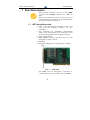
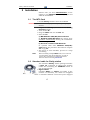
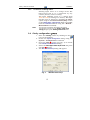
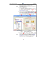
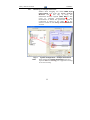
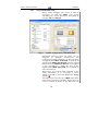
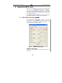
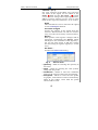
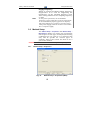
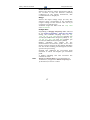
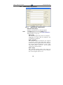
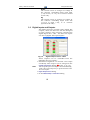
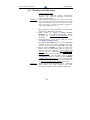
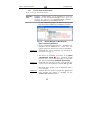
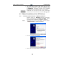
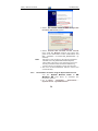
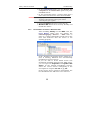
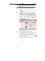
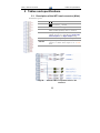
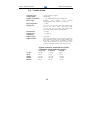
Clarity
Clarity Hardware
INT9 A/D converter
INT9 A/D converter
ENG
Code/Rev.: M105/25B – 11 July 2007
Phone: +420 - 251 013 400
Fax: +420 - 251 013 401
[email protected]
www.dataapex.com
© DataApex Ltd. 2007
Podohradská 1
155 00 Prague 5
The Czech Republic
Sections of the manual connected only to the Clarity Full version are
marked with the
icon and grey stripe to the right of the text.
®
Clarity®, DataApex® and
are trademarks of DataApex Ltd.
®
TM
Microsoft and Windows are trademarks of Microsoft Corporation
DataApex reserves the right to make changes to manuals without prior notice.
Updated manuals can be downloaded from www.dataapex.com
Clarity - INT9 A/D converter
Table of Contents
1 Brief Description............................................................4
1.1 INT9 Acquisition card ...........................................4
1.2 Hardware and software requirements....................5
2 Installation ....................................................................6
2.1 The INT9 Card ......................................................6
2.2 Standard cable for Clarity station .........................6
2.3 Connection with Chromatograph ..........................7
2.3.1 Connecting signal cables:............................8
2.3.2 Connection of starting cables: .....................9
2.4 Clarity configuration
...............................9
2.4.1 Measuring on multiple Instruments .......... 11
2.4.2 Using multiple INT9 cards......................... 12
3 Using the INT9 card ..................................................... 14
3.1
3.2
INT9 A/D Card Setup
............................ 14
Method Setup ..................................................... 16
3.2.1 Method Setup - Acquisition ....................... 16
3.2.2 Method Setup - Measurement ................... 18
3.3 Digital Inputs and Outputs ................................. 19
4 Troubleshooting........................................................... 20
4.1 Locate your problem: .......................................... 20
4.2 Problems with INT9 driver .................................. 21
4.2.1 How to check the INT9 driver: ................... 22
4.3 Manual Installation of the INT9 drivers ............... 23
4.3.1 Instalation and reinstalation in
Windows XP/Vista .................................... 23
4.3.2 Reinstallation of drivers using the
System Restore Point ................................ 24
4.3.3 Reinstallation of drivers in Windows
2000......................................................... 25
4.4 Data Acquisition – non-functional....................... 29
4.5 Data Acquisition - Simulated .............................. 30
5 Tables and specifications ............................................. 32
5.1 Description of the INT9 card connector
(Male) ................................................................. 32
5.2 Parameters of digital Inputs and Outputs............ 33
5.3 INT9 - CE Conformity Declaration....................... 34
5.4 Technical Data ................................................... 35
3
Clarity - INT9 A/D converter
Brief Description
1 Brief Description
This manual describes the use of the INT9
converter with Clarity software ver. 2.5 and
later.
INT9 is an internal 24-bit A/D converter card
that measures the voltages of chromatographic
and electrochemical detectors.
1.1
INT9 Acquisition card
• Up to 4 dataacquisition channels on one card
(one and two channel versions are also
available).
• The channels are completely independent
sigma delta integrating A/D converters, used
for processing positive and negative voltages.
• Four digital inputs.
• Eight digital outputs. The first four are also
designed as relay contacts.
• PCI Slot.
• Excellent reliability and temperature stability.
Fig. 1.
INT9 Card
The INT9 card of integration converters is
a modernized successor of the PCI card INT7.
4
Clarity - INT9 A/D converter
Brief Description
A/D Converter types in general
Prior to collecting and processing the chromatographic signal by a computer, the analog
signal of the detector must first be converted to
digital form using an analog/digital (A/D)
converter.
In principle, there are three types of A/D
converters – sampling, integrating and ΔΣ
(Delta-Sigma - with continuous integration).
The INT9 card uses Delta-Sigma integration.
Advantages of the INT9 A/D converter
• No loss of input signal during integration.
There are no time delays during which the
converter fails to integrate the input signal.
• No continuous servicing of the input analog
switches, which would otherwise cause errors
(offset, noise).
• Substantially smaller amounts of data entering
the computer due to individual data items
already representing partial integrals.
1.2
Hardware and software requirements
The INT9 A/D Converter for PCI slot can be
used with Clarity software on PC’s using the
following operating systems: MS Windows
2000/XP/Vista.
The PC must have one free PCI slot for your
INT9 card.
Caution!
Full size PCI 2.0, 32 bit PCI slot is required. Low
profile or PCI Express slots cannot be used.
Hardware and Software Compatibility:
Software \ Windows
Vista
XP
2000
NT
98/Me
Clarity *
Yes
Yes
Yes
No
No
Clarity Lite *
Yes
Yes
Yes
No
No
CSW32
No
No
No
No
No
* From Clarity version 2.4.4.122
5
Clarity - INT9 A/D converter
Installation
2 Installation
Ensure that you have Administrator access
rights to your Windows OS before you proceed
with the installation.
2.1
The INT9 Card
• Install Clarity software from the CDROM.
Caution!
Install the Clarity software before inputting any
devices.
• Plug in the HW Key (described in the Getting
Started manual)
• Turn off the PC
• Plug the INT9 card into the PCI slot
• Start the PC
a) MS Windows 2000/XP/Vista and later
In Windows 2000/XP/Vista the drivers were
installed automatically during the installation
of the Clarity software.
b) Previous versions of MS Windows
In systems other than Windows 2000/XP/
Vista follow the procedure described in chapter
4.3 on pg. 23.
• The driver is now installed, proceed to setup
and wiring.
Note:
2.2
When installing multiple INT9 cards, a PC restart is
recommended, after the installation, in order to
prevent the reassignment of INT9 acquisition
channels between Clarity Instruments.
Standard cable for Clarity station
The standard Clarity station package includes
a cable set composed of signal and starting
cables for connecting the CLARITY station to
the chromatograph.
• Signal cables
Labelled “DET1” to “DET4” (according to the
number of channels), the cables are supplied
as standard without connectors [bare stripped
6
Clarity - INT9 A/D converter
Installation
and tinned endings – red (+), white (-) and
shielding (analogue ground)].
• Starting (marker) cables
Labelled “IN1” to “IN4” (correlating to channel
number) and tipped with CINCH connector
(female).
The following cables can be connected to this
CINCH connector:
• A cable terminated with free leads [red (+),
shielding
(digital
ground)]
for
direct
connection to the chromatograph.
• A cable terminated with a button for cases
where a starting contact is not available and
it is necessary to perform a manual start.
Both types of cable are supplied for each
starting cable.
• Digital output cables
Relay contacts labelled "OUT1R" to "OUT4R"
(according to the number of channels),
terminated with free leads. These are used for
synchronizing autosamplers without an AS
Control module in the Active Sequence or for
controlling other devices.
At the converter end the cable is always
terminated with a D-SUB 37-pin connector
(female).
2.3
Connection with Chromatograph
Connect the cables according to one of the
following diagrams in Fig. 2. Use the
symmetrical connection only when you are
sure that the chromatograph/detector is
equipped with a symmetrical output – it is
necessary to read through the instructions for
the corresponding chromatograph.
All current DataApex A/D Converters INT7,
INT9, U-PAD, U-PAD2 and Net-PAD use the same
standard INT7 Connector.
Note:
A description of the INT7 connector can be found in
chapter 5.1 on pg. 32.
7
Clarity - INT9 A/D converter
Installation
Digital output (Relay)
Starting cable
Red
Shielding
Signal cable
Red
White
START (REMOTE, …)
1V (100mV, Hi, +, …)
0
(COM, AGND, …)
Shielding
NONSYMMETRICAL CONNECTION
Digital output (Relay)
Starting cable
Red
Shielding
Red
Signal cable
White
Shielding
SYMMETRICAL CONNECTION
Fig. 2.
2.3.1
START (REMOTE, …)
+
(+1V, Hi, …)
-
(-1V, Lo, …)
COM (0, GND)
Connecting Clarity to chromatograph
Connecting signal cables:
Signal inputs of the A/D converters are
symmetrical: + (red), - (white) and analogue
ground (copper braiding).
Caution!
Shielding must be connected. It serves not only as
the shielding but also as the analogue earth
against which the measurement takes place. In
the case of asymmetrical output of a detector (only
two connectors) the shielding must be connected
to the white lead! No lead of the signal cable may
remain unconnected.
Try to connect to the detector output of the
chromatograph with the largest possible signal
level, usually indicated as INTEGRATOR
(signal approx. 1V). The level of the signal on
the output marked RECORDER is usually only
approx. 10mV.
For easier alterations of the wiring, we supply a
SV8 Terminal board with screw contacts for
INT7, INT9, U-PAD, U-PAD2 and Net-PAD
A/D converters.
Note:
This SV8 Terminal Board is not suitable for
applications with small signals or with high
electromagnetic interference. This is because the SV8
Terminal Board uses leads and screw contacts that
are not shielded.
8
Clarity - INT9 A/D converter
2.3.2
Installation
Connection of starting cables:
Starting input reacts to a change of the TTL
logical level (5V) or to a connection by any
contact (button, contact of relay).
The input implicitly reacts to a change from
HIGH to LOW (or closing of a contact). The input
function may be altered by changing the Down
option to Up in the External Start/Stop section
of the Method Setup - Measurement dialog (accessible
from the Instrument window using the - Method Measurement command).
Note:
2.4
For schemes and hints describing the typical
autosampler wirings see the Device setup and
wiring chapter of the Getting Started Manual.
Clarity configuration
1. Start the Clarity station by clicking on the
icon on the desktop.
2. Invoke the System Configuration dialog using the
System – Configuration command.
3. Press the Add
button (see Fig. 4) to invoke
the Available Control Modules dialog.
4. Select the DataApex INT9 A/D Card and press
the Add
button.
5. The INT9 A/D Card Setup dialog will appear.
Fig. 3.
INT9 A/D Card Setup
9
Clarity - INT9 A/D converter
Installation
6. Enter the detector names in Name fields for
individual channels, set signal units.
Note:
A detailed description of this dialog can be found in
chapter 3.1 on pg. 14.
7. Press the OK button.
The DataApex INT9 A/D Card will appear in
the Setup Control Modules list
of the
System Configuration dialog.
8. Drag and drop the DataApex INT9 A/D Card
icon from the Setup Control Modules list
on the left side of the System Configuration dialog
to the desired Instrument
tab on the right
side
(or use the
button
to do so).
Fig. 4.
System Configuration
9. Set the Start input and Ready output
numbers
for your acquisition card according
to the wires being used for synchronization.
Note:
The configuration dialog of the INT9 card (INT9 A/D
Card Setup) can be displayed any time by doubleclicking on its icon or using the Setup button.
10
Clarity - INT9 A/D converter
2.4.1
Installation
Measuring on multiple Instruments
Rather than dragging the entire INT9 A/D
Card Driver icon from the Setup Control
Modules list
(see Fig. 5), drag the
individual detector signals (TCD, FID in this
case)
to
separate
Instruments .
The
Instrument to which the particular signal is
connected is listed to the right
of the
detector name in the Setup Control Modules
section.
Fig. 5.
Note:
System Configuration – multiple Instruments
Each independent Clarity Instrument must have
separate Start and Ready pins configured according
to the actual wiring.
11
Clarity - INT9 A/D converter
2.4.2
Installation
Using multiple INT9 cards
When using multiple A/D cards, it will be
necessary to add the INT9 card again,
repeating the entire procedure described in
chapter 2.4 from Step 3.
Fig. 6.
System Configuration – two INT9 cards
Individual detectors from all cards can be
assigned
to
multiple
instruments
and
combined together arbitrarily. In this example,
all signals from INT7 A/D Card, as well as all
signals from INT9 A/D Card 2 and one signal
(Pressure) from INT9 A/D Card 1 are assigned
to the instrument 1, while the rest of the
signals from INT9 A/D Card 1 is assigned to
the Instrument 2.
While there are several cards assigned to the
same instrument, it is necessary to select
which card will be used for Start and Ready
signals .
All added A/D converters (e.g. INT9) must have
their drivers properly installed. There must be
correct number of items in the Windows OS
12
Clarity - INT9 A/D converter
Installation
Device Manager, otherwise you will not be
able to add it in the System Configuration dialog
and configure its detectors to Clarity
Instruments.
Fig. 7.
Note:
Device Manager – two INT9 cards
A maximum of four INT9 cards can be configured
and used in Clarity simultaneously.
13
Clarity - INT9 A/D converter
Using the INT9 card
3 Using the INT9 card
There are generally two places for setting the
parameters of INT9 A/D Converter in Clarity.
• The INT9 A/D Card Setup dialog for setting the
parameters that are set with respect to the type
of connected signal.
• The Method Setup – Acquisition tab for setting the
parameters related to the type of analysis.
3.1
INT9 A/D Card Setup
The INT9 A/D Card Setup dialog sets the
parameters of the INT9 converter and since it
depends on the type of connected detector, it is
not going to be changed often.
Fig. 8.
INT9 A/D Card Setup
Number of Channels
Indicates the number of channels detected on
the card.
14
Clarity - INT9 A/D converter
Using the INT9 card
Channel 1 (to 4)
For each channel of the INT9 A/D Converter
the name of the signal can be edited in the
Name
field and the Set Units...
button
can be used to change other signal parametres.
Effects of these changes can be seen in other
fields of the respective Channel 1 (to 4) section.
Name
This field will be used to describe the signal
in the Chromatogram window.
Inversion of Signal
Inverts the polarity of the signal from the
detector. This function can also be used for
easy correction of inversely connected wires.
Bipolar
Both positive and negative voltages will be
measured. Unchecking the Bipolar option
will improve the resolution of the signal by 1
bit. On the other hand, it will also restrict
the measuring of negative signals (i.e. below
zero).
Set Units...
Invokes the Detector Units dialog.
Fig. 9.
Detector Units
• Quantity – Field for entering the quantity of
the units.
• Units – Field for entering the unit symbol,
along with the prefix.
• Coefficient – Allows to enter the coefficient
between the selected units and mV (default).
• Autoprefix – Allows to enter the unit prefix.
In graphs, units will be scaled automatically,
while in the tables, units with the prefix
entered will be used.
15
Clarity - INT9 A/D converter
Using the INT9 card
Supply Frequency
Allows to change the Mains Supply Frequency
Suppression. It is used for suppresing the
interference on the specified frequency level.
This setting influences the sampling frequency
as well.
Note:
3.2
In most parts of Americas, the 60 Hz Mains
frequency is usual, while the rest of the world tends
to use 50 Hz Mains frequency (pre-set as default).
The 50 Hz frequency is common in countries using
230V power supply, while the 60 Hz is connected to
the 117V power supply.
Method Setup
The Method Setup – Acquisition and Method Setup –
Measurement dialogs are where the parameters
that depend on the type of analysis (measuring
conditions) are set and so it is expected that
they will be specific for various types of
analysis. This is the reason for them to be a
part of the method.
Caution!
3.2.1
Parameters cannot be changed during analysis.
Method Setup - Acquisition
Fig. 10.
Method Setup - Acquisition (INT9)
16
Clarity - INT9 A/D converter
Using the INT9 card
Select Detector
Selects the detector whose parameters will be
set. If there is only one detector (channel)
configured on the Clarity Instrument, this
control will not be displayed.
Range
Selects the input voltage range (in mV). The
selected range corresponds to the maximum
output voltage of the detector that the A/D
converter can still process.
Available ranges for INT9 card are 156, 1250
and 12 123 mV.
Sample Rate
Depending on Supply Frequency filter selected
in the System Configuration - INT9 A/D Card Setup
dialog, the available sampling rates are 6.3,
12.5, 25, 50, 100, 200 and 400 samples per
second (for 50Hz mains frequency filter) or 7.5,
15, 30, 60, 120, 240 and 480 samples per
second (for 60Hz mains frequency filter).
Higher
sampling
rate
allows
for
the
measurement of narrower peaks, but it also
means a larger amount of data which will affect
the size of the resulting chromatogram and the
speed of its processing.
Sample rate sufficient for successful peak
detection is about 20 samples per narrowest
peak.
A higher sampling rate also increases the
amount of noise.
Note:
Range and Sample Rate are set individually for
each detector, as opposed to Mains Frequency set
for the INT9 A/D card as a whole.
17
Clarity - INT9 A/D converter
3.2.2
Using the INT9 card
Method Setup - Measurement
Fig. 11.
Method Setup - Measurement
External Start/Stop
Enables control from an external signal.
Note:
The Input used for an external Start from a
chromatograph can be set in the System Configuration
dialog (see Fig. 4 on pg. 10).
Start Only
The external signal only starts an analysis.
Triggering the input will not influence the
acquisition in progress.
Start - Restart
The external signal terminates the analysis
in progress and at the same time starts a
new one. The first signal starts the analysis;
the second signal terminates it and at the
same time starts a new one - the so-called
continuous measurement.
Start - Stop
The external signal starts and stops an
analysis. The first signal starts the analysis;
the second signal stops it, etc.
18
Clarity - INT9 A/D converter
Using the INT9 card
Down
The station reacts to changes in voltage in
the relevant controlling input from high
(> 3V) to low (< 0.7 V), or to contacts closed
in the relay.
Up
The station reacts to changes in voltage in
the relevant controlling input from low
(< 0.7 V) to high (> 3V), or to contacts
opened in the relay.
3.3
Digital Inputs and Outputs
The INT9 converter contains eight digital TTL
outputs, where the first four are also designed
as relay contacts. The converter contains four
digital inputs IN1 - IN4. The first two inputs
are also equipped with optocouplers.
Fig. 12.
Digital Output Control – INT9
These outputs can be controlled from the
following places in Clarity:
• Standard assignment of external start Input
and Ready OUT Output can be changed in the
System Configuration dialog (
in Fig. 4, pg. 10).
Note:
The assigned input and output is then automatically
used in the Active Sequence for synchronization with
the autosampler.
• Digital Output Control dialog.
• In the Method Setup – Event Table dialog.
19
Clarity - INT9 A/D converter
Troubleshooting
4 Troubleshooting
If you will not find your answers here, use the
www.dataapex.com website where the Support
menu will navigate you to frequently asked
questions (FAQ), Clarity email conference
archive or contact to DataApex helpdesk.
4.1
Locate your problem:
When troubles occur, the fastest way to find a
solution for it is to search for it in the following
index via the Dialog (window), in which the
problem occured, Error Messages that apear
or according to utilized Hardware. The name of
the window/dialog is visible in its header.
Names of individual Clarity Instruments
appear in the header instead of the common
term “Instrument”.
Dialog
-
Clarity
Data Acquisition
Instrument
Method Setup
Sequence
Single Analysis
System Configuration
30
30
29
29
29
29
21, 29, 30
Error Messages
-
Board malfunction
Cannot create detector
Cannot find driver file ...
Cannot find first board
Cannot find second board
Disabled (in the status line)
Error Occurred During Setup
Simulated (in Data Acquisition)
Note:
21
21
21
21
21
29
21
30
To find solutions for error messages not listed above,
check the Clarity Getting Started Guide or visit our
web pages (www.dataapex.com).
20
Clarity - INT9 A/D converter
4.2
Troubleshooting
Problems with INT9 driver
• “Board malfunction”
If the error message "Board malfunction"
appears, the card is probably incorrectly
inserted or damaged.
Solution: Check whether the INT9 A/D card is correctly
set in the ISA slot. The card should be tucked
fully and should not move in the slot. If this
does not help, contact technical support to
replace the damaged card.
•
•
•
•
•
Solution:
Most problems with INT9 driver are generally
indicated by following symptoms:
INT9 cannot be added to Setup Control
Modules in the System Configuration dialog,
showing the "Cannot create detector" error
message.
Double-clicking on the device will not invoke
the INT9 A/D Card Setup dialog.
The Data Acquisition icon in the Instrument
window is not active (this problem may also
have another cause. See section 4.4 on pg. 29).
When starting Clarity or trying to add more
INT9 cards to configuration then is present in
the PC, the error message “Cannot find first
board” appears. Alternatively, “Cannot find
second board” error message may appear.
While trying to add the INT9 card in System
Configuration dialog or while starting Clarity,
"Cannot find driver file ..." error message with
path to the INT9 drivers in the system followed
by "Error Occurred During Setup" appeared.
When one of these problems occur, check the
INT9 driver (see next chapter) and then
procced according to the suggested solutions.
21
Clarity - INT9 A/D converter
4.2.1
Troubleshooting
How to check the INT9 driver:
How to check the INT9 driver:
Windows
2000/XP/
Vista
In the Start menu (lower left corner of the screen), select
Settings – Control Panel, and the System icon; under the
Hardware tab click the Device Manager button and in the
resulting list look for the Chromatography Devices DataApex Acquisition Device Model 9.xx item.
In the following image, all drivers (except for
the driver for U-PAD2) are installed correctly.
Fig. 13.
Device Manager in Windows XP
Error status of the driver:
• If the “Chromatography Device – DataApex Acquisition device, Model 9.xx” - item does not
appear, then the driver has not been installed.
Solution: Reinstall the driver manually as described in
section 4.3 on pg. 23.
• The driver is installed, but there is a yellow
(or a question mark)
exclamation mark
over its icon, or it is not behaving as expected.
The driver is probably installed incorrectly.
Solution: Uninstall the incorrect driver and install the
correct one as described in section 4.3, pg. 23.
• The item does appear, but is displayed with a
cross symbol.
Solution: Double-click the item to invoke the General tab
and activate the driver by clicking on the
Enable this device button.
22
Clarity - INT9 A/D converter
Troubleshooting
• The item does appear and there are no error
symbols around it. A driver for a different type
of Windows operating system was possibly
installed thereby replacing the correct driver.
Solution: Uninstall the incorrect driver and install the
correct one as described in section 4.3, pg. 23.
4.3
4.3.1
Manual Installation of the INT9 drivers
Instalation and reinstalation in Windows XP/Vista
During start-up, Windows should automati–
cally recognize the new Plug and Play device
and start the hardware installation wizard.
Note:
If this does not occur, use the Start - Control Panel
– Add Hardware to invoke installation.
• Choose the Next possibility.
• Select: No, not this time and hit Next.
23
Clarity - INT9 A/D converter
Troubleshooting
• Select the Install from a list or specific
location (Advanced) option.
• Select Include this location in the search;
here click the Browse button and select the
path to the main folder of the workstation and
INT subfolder (C:\CLARITY\HW_DRIVERS\INT9 by
default).
Note:
The driver is also located on the Clarity installation
CD ROM in the HW_DRIVERS\INT9\XXX subfolder,
where XXX is the type of your operating system. NT
stands for Windows NT, while 2000 subdirectory
contains drivers for Windows 2000, XP and Vista.
• The rest of the installation will be carried out
automatically.
4.3.2
Reinstallation of drivers using the System Restore Point
Use the System Restore Point in MS
Windows XP (and later) to uninstal the
incorrect drivers.
• Go to Start - Programs – Accessories –
System Tools – System Restore.
24
Clarity - INT9 A/D converter
Troubleshooting
• In the System Restore dialog use the Restore my
computer to an earlier time option and press
the Next button.
• In the next dialog select a restore point from a
time before the incorrect driver was installed.
Caution!
Any soft- or hardware that was installed after the
moment of the selected restore point will be
removed from your system.
• Reinstall Clarity and then restart the PC.
• Windows XP should now correctly identify and
install the drivers.
4.3.3
Reinstallation of drivers in Windows 2000
After installing Clarity and the INT9 card, the
Device Manager either does not display the
Chromatography Devices – INT9 item or
there is a yellow exclamation mark next to the
item that indicates that the device is not
working properly.
If the "DataApex Acquisition device, Model 9.xx"
item is missing, Windows has automatically
installed an incorrect driver.
If you are able to locate which device was
mistakenly installed instead of the INT9 driver,
you can open its Properties and Update this
driver. In the manual installation process,
select the correct drivers analogically to the
description in chapter 4.3.3.2 on pg. 26.
If the correct driver cannot be determined, the
last installed driver will have to be removed.
25
Clarity - INT9 A/D converter
Caution!
Troubleshooting
This procedure can only be used safely if no other
hardware has been installed since the installation
of the card.
4.3.3.1
Deleting incorrect *.inf files in the system
Note:
Be sure to have the Clarity software installed
already.
• In Windows
folder .
Note:
Explorer
open
the
C:\WINNT\INF
You may have to allow for the hidden system files to
be displayed. In the menu select Tools – Folder
Options -> View tab then set the Hidden Files and
Folders option to Show Hidden Files and Folders.
• Sort the files according to Modified column
and locate the last modified *.PNF file .
• Also locate the corresponding *.INF file
and
delete both of them.
• Continue to install the correct driver manually
without restarting the PC.
4.3.3.2
Installing the correct driver manually
The following procedure can be applied under
any circumstances; this is why the most
universal option is described step by step.
• Invoke the Start – Control Panel –
Add/Remove Hardware
• In the first dialog press the Next button.
26
Clarity - INT9 A/D converter
Troubleshooting
• Select Add/Troubleshoot a device and press
the Next button.
• In the Devices list select Add a new device
and press the Next button.
27
Clarity - INT9 A/D converter
Troubleshooting
• Select No, I want to select the hardware
from a list and press the Next button.
• In the Hardware types list select the Other
devices option and press the Next button.
• Click the Browse button to navigate to the
driver located in the (C:\CLARITY\HW_DRIVERS\INT9)
Clarity directory. Then press the Next button.
28
Clarity - INT9 A/D converter
Troubleshooting
• In the Models list select the DataApex
Acquisition device, Model 9.00 and press the
Next button.
• In the remaining dialogs press the Next
button.
• Restart the PC.
• Re-check the driver in the Device Manager as
desribed in chapter 4.3.3.
4.4
A gray
Data Acquisition – non-functional
icon, label “Disabled”, and Data Acquisition command not functional
Other manifestations of this error are also:
Method Setup - Acquisition tab missing, Method –
Acquisition command non-functional, Run,
Stop, Abort commands non-functional in the
windows Single Analysis and Sequence).
Possible causes are:
a) Detector not allocated to instrument:
Solution:
Open the System Configuration dialog from the
main Clarity window using the System Configuration command and check the tab of
the corresponding instrument - Instrument x. If it
has no allocated detectors, add them.
In the left-hand list Setup Control Modules
select the correct detector that is connected to
the A/D card you are using and link it to the
corresponding instrument on the right.
29
Clarity - INT9 A/D converter
Troubleshooting
If your A/D card is not in the left-hand Setup
Control Modules list, add it using the Add
button and repeat the previous step.
Note:
More information on configuration of the INT9 card is
in chapter 2.4 - Clarity configuration on pg. 9.
b) You have a licence purchased for collections from a smaller
number of instruments:
Solution:
Open the System Configuration dialog from the
main Clarity window using the System Configuration command and check the tab of
the corresponding instrument – Instrument x.
Blue symbol of the curve in the tab header
indicates an Instrument not usable for
measuring.
Check your serial number S/N (for example)
using the Help - About command from the
main Clarity window.
c) You are using Clarity Offline or a DEMO version, which does
not enable the measurement of chromatograms.
Solution:
4.5
Check whether there is a blue line with the title
OFFLINE displayed in the main Clarity window
under the symbols of the instruments, or the
title DEMO in the window header.
Data Acquisition - Simulated
The label “Simulated” is displayed in the Data Acquisition window
Solution:
The corresponding instrument only displays
the simulated curve (from the file CHANNX.DTA),
or is allocated as what is known as a DEMO
driver.
Open the System Configuration dialog from the
main Clarity window using the System Configuration command and check the tab of
the corresponding instrument - Instrument x.
From the list of equipment allocated to the
instrument, remove the Detector x from DEMO
driver field and draw the correct detector of the
A/D card you are using from the list on the
left.
30
Clarity - INT9 A/D converter
Troubleshooting
If you only have Demo detectors in the lefthand Setup Control Modules list and your
A/D card is missing, open the Available Control
Modules dialog and, using the Add button, add
it to the configuration of the station. Then
repeat the previous step.
31
Clarity - INT9 A/D converter
Tables and specifications
5 Tables and specifications
5.1
Description of the INT9 card connector (Male)
Connector pins:
1H
+ Input of the 1st channel
1L
- Input of the 1st channel
AGND1
Ground of the 1st channel
IN1
Digital input (of the 1st channel). Used as an
External Start (marker) of the 1st channel
OUT1
1st Digital output
Digital outputs are controlled by Event Table,
Active Sequence and Digital Output dialog.
DGND
Ground of the digital inputs and outputs.
OUT1S1,
OUT1S2
Digital outputs - 1st relay contact.
Contact is closed when output is at a LOW
level.
Fig. 14.
Standard INT7-compatible cable for two
detectors
32
Clarity - INT9 A/D converter
5.2
Tables and specifications
Parameters of digital Inputs and Outputs
The card contains eight digital TTL outputs
(OUT1-OUT8) with a maximum permissible
current of 20 mA at both levels. The first four
outputs are also designed as relay contacts
(OUT1S1/OUT1S2- OUT4S1/OUT4S2).
The maximum permissible current is 100 mA,
the maximum-switched voltage is 100 V and
the contact resistance is 150 mΩ. The relay is
onstate (closed) when there is a LOW level of a
relevant digital output.
The card contains 4 digital inputs IN1 to IN4.
To suppress contact bouncing the digital
inputs are equipped with monostable toggles
that prolong any change affecting the input to
at least 200 ms (to ensure that the station is
able to detect it).
A pulse with duration of at least 1 ms is
necessary in order to excite the toggles.
33
Clarity - INT9 A/D converter
5.3
Tables and specifications
INT9 - CE Conformity Declaration
34
Clarity - INT9 A/D converter
5.4
Tables and specifications
Technical Data
Converter type:
24-bit ΔΣ (delta – sigma)
Analog inputs:
differential
Number of channels:
1, 2 or 4 fully independent and isolated
Input range:
Unipolar
and
bipolar,
each
channel
independentely 156, 1 250 or 12 123 mV
Input impedance:
> 1 MΩ
Sample rate:
6.3, 12.5, 25, 50, 100, 200, 400 samples per
second for 50Hz mains frequency filter
7.5, 15, 30, 60, 120, 240, 480 samples per
second for 60Hz mains frequency filter
Non-linearity:
< 0.003 %
Temperature
dependence
< 10 ppm/°C
Digital inputs:
4 TTL (5V)
Digital outputs:
8 TTL (5V, maximum current load per output 20
mA, maximum total current load 100mA), the
first four control relays (switching contacts
rating: max. switching current 0.5 ADC, max.
contact resistance 150mΩ, max. voltage 100V)
Typical noise free resolution for various
acquisition speeds and input ranges:
12 123 mV
1 250 mV
156 mV
6.3 Hz
21.5 bit
21.5 bit
20 bit
25 Hz
21 bit
21 bit
20 bit
100 Hz
19.5 bit
19.5 bit
19.5bit
200 Hz
16.5 bit
16.5 bit
16.5 bit
400 Hz
16 bit
16 bit
16 bit
35