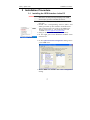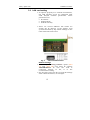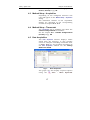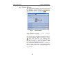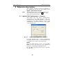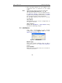
1
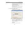
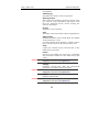
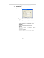
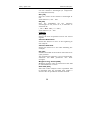
Clarity Controls
Clarity
Controls
Agilent
1100
Agilent 1100
LC
ENG
Code/Rev.: M060/24D – 19. October 2007
Phone: +420 - 251 013 400
Fax: +420 - 251 013 401
[email protected]
www.dataapex.com
© DataApex Ltd. 2007
Podohradská 1
155 00 Prague 5
The Czech Republic
are trademarks of DataApex Ltd.
Clarity®, DataApex® and
Microsoft® and WindowsTM are trademarks of Microsoft Corporation
DataApex reserves the right to make changes to manuals without prior notice.
Updated manuals can be downloaded from www.dataapex.com.
Clarity - Agilent 1100
Table of Contents
1 Agilent 1100 Control Module..........................................5
2 Requierements...............................................................6
3 Installation Procedure ....................................................7
3.1 Installing the GPIB interface in the PC ..................7
3.2 LAN card setting ...................................................9
3.3 Clarity configuration........................................... 11
3.3.1 Assign the control to Clarity
Instrument ............................................... 14
3.4 First start of Clarity after configuration ............... 14
4 Using the Control Module ............................................ 16
4.1 Method Setup – AS Control ................................. 16
4.2 Method Setup – LC Control ................................. 16
4.3 Method Setup - Acquisition................................. 17
4.4 Method Setup - Thermostat ................................ 17
4.5 Data Acquisition................................................. 17
4.6 Device Monitor ................................................... 19
5 Reference description................................................... 20
5.1 Agilent 1100 Configuration – Common ................ 20
5.2 Add Module ........................................................ 21
5.3 Autosampler AS (G1313) and TAS (G1329).......... 22
5.3.1 Agilent 1100 Configuration –(T)AS ............. 22
5.3.2 Method Setup – AS Control - Injection ....... 22
5.3.3 Method Setup - AS Control - Program........ 24
5.3.4 Hardware Configuration - AS .................... 26
5.4 DAD (G1315) ...................................................... 27
5.4.1 Agilent 1100 Configuration - DAD ............. 27
5.4.2 Method Setup – Acquisition - Signal .......... 28
5.4.3 Method Setup – Acquisition –DAD ............. 30
5.4.4 Method Setup – Acquisition - Outputs ....... 31
5.4.5 Method Setup – Acquisition –Time
Table ........................................................ 32
5.4.6 Hardware Configuration - Main ................. 33
5.4.7 Hardware Configuration - Info................... 34
5.5 FLD (G1321)....................................................... 34
5.5.1 Agilent 1100 Configuration - FLD .............. 34
5.5.2 Method Setup – Acquisition - FLD
Parameters ............................................... 35
3
Clarity - Agilent 1100
Table of Contents
5.5.3
Method Setup – Acquisition Flashlamp ................................................ 38
5.5.4 Method Setup – Acquisition - Outputs ....... 39
5.5.5 Method Setup – Acquisition - Time
Table ........................................................ 40
5.5.6 Hardware Configuration - Main ................. 41
5.5.7 Hardware Configuration - Info................... 41
5.6 MWD (G1365)..................................................... 42
5.6.1 Agilent 1100 Configuration - MWD ............ 42
5.6.2 Method Setup – Acquisition - Signal .......... 43
5.6.3 Method Setup – Acquisition - MWD ........... 45
5.6.4 Method Setup – Acquisition - Outputs ....... 46
5.6.5 Method Setup – Acquisition – Time
Table ........................................................ 47
5.7 VWD (G1314) ..................................................... 48
5.7.1 Agilent 1100 Configuration - VWD............. 48
5.7.2 Method Setup – Acquisition - Signal .......... 49
5.7.3 Method Setup – Acquisition - VWD............ 51
5.7.4 Method Setup – Acquisition - Outputs ....... 52
5.7.5 Method Setup – Acquisition – Time
Table ........................................................ 53
5.8 LC Pump (G1310, G1311, G1312)....................... 53
5.8.1 Options..................................................... 57
5.9 Column Compartment (G1316) ........................... 58
5.9.1 Agilent 1100 Configuration –AS................. 58
5.9.2 Method Setup – Thermostat –
Temperature ............................................. 58
5.9.3 Method Setup - Thermostat – Time
Events ...................................................... 60
6 Connections ................................................................ 61
6.1 Wiring ................................................................ 61
6.2 Description of connectors: .................................. 61
6.2.1 LAN interface ............................................ 61
6.2.2 GP-IB communication ............................... 62
6.3 Recommended GPIB addresses: .......................... 62
7 Troubleshooting........................................................... 63
Commdrv.log utility ..................................................... 65
4
Clarity - Agilent 1100
Agilent 1100 Control Module
1 Agilent 1100 Control Module
•
•
•
•
The Agilent 1100 driver can control Agilent
1100 series and 1200 series (in 1100
emulation mode) HPLC systems with:
DAD, MWD, VWD, FLD and RID detectors
Quarternary, Binary and Isocratic Pumps
Column compartments
Autosamplers (standard and thermostated)
Fig. 1.
Agilent 1100
The direct control can be performed via
• 82357A USB/GPIB Interface
• 82350A PCI/GPIB Interface
• LAN
Note:
The 82355 and 82431 ISA/GPIB Interfaces are
not supported
Data Acquisition can be performed via
• GPIB – Clarity Digital Data Acquisition
• LAN – Clarity Digital Data Acquisition
• ANALOG – analog signal to A/D converter (e.g.
INT7 or U-PAD).
5
Clarity - Agilent 1100
Requierements
2 Requierements
• Clarity Installation CD ROM with LC Control
module (p/n A24).
• AS control module (p/n A26) when the
autosampler is used.
• PDA Extension (p/n A29) when the DAD or
FLD detector is used.
• Cross LAN cable (p/n SK08) and the LAN card
in the PC for the newer Agilent 1100 and all
Agilent 1200 systems. For older Agilent 1100
systems, GPIB interface may be necessary.
This consists of:
• either 82357A PCI/GPIB interface card
(IAG11), GPIB cable (p/n GPIB) and free PCI
slot in the PC.
• or 82350A USB/GPIB interface card and
free USB port in the PC.
Caution!
Note:
Check your Agilent 1100 for available communication options. In older systems, the LAN communication interface was optional and HP-IB
standard. In recent new systems and in the 1200
series modules the HP-IB port is no more present.
Cables are not part of Clarity Control Module. It is
strongly recommended to order required cables
together with the Control Module.
6
Clarity - Agilent 1100
Installation Procedure
3 Installation Procedure
3.1 Installing the GPIB interface in the PC
Caution!
If you are using the 82357A USB/GPIB Interface,
then leave out the first step and plug in the GPIB
device after you have installed the drivers.
• Insert the 82350A PCI/GPIB Interface in the
PCI slot.
• Install the corresponding drivers (SICL and
VISA) provided by the interface manufacturer.
Note:
The communication was tested on the GPIB driver
library version M01.01. The IO libraries are also
available on www.agilent.com/find/iolib.
• (Plug in the 82357A USB/GPIB Interface).
• In the right part of the Windows taskbar click
the IO icon.
• In the Agilent IO Libraries Configuration dialog select
your GPIB card.
• Press Edit to invoke the Card Configuration
dialog.
7
Clarity - Agilent 1100
Installation Procedure
Fig. 2.
87350 PCI GPIB Card Configuration
• Set the SICL Interface Name.
The BUS Address must be different from the
address of any of the other components in the
Agilent 1100 configuration – recommended
values are 21 or 30 (21 is offered as default).
Note:
Should the setting be compatible with the
Chemstation the SICL Interface Name must be
"HP82341")
Write down the SICL Interface Name and BUS
Address fields it will be necessary to set these
values later also to the Clarity Agilent 1100
Configuration dialog.
• Connect the Agilent 1100 to the PC by GPIB
interface.
Caution!
It is recommended to connect the GPIB cable
between the PC and the Agilent 1100 component
with the largest amount of communication. This is
usually the DAD detector. If it is not present in the
set then any other detector (MVD, WVD, FLD, etc.)
• Turn the power on (both PC and Agilent 1100).
• Review the GPIB settings.
8
Clarity - Agilent 1100
Installation Procedure
3.2 LAN card setting
• To operate properly in a network environment,
the LAN Interface must be configured with
valid TCP/IP network parameters. These
parameters are:
• IP address
• Subnet Mask
• Default Gateway
• There are several different Init modes for
setting the IP address of the Agilent 1100
system selectable by dip switch settings on the
LAN communication board.
Fig. 3.
LAN card DIP Switches
Default settings
• The factory set “Using Default” option (SW5
ON and SW6 ON) uses fixed IP address
192.168.254.11. In case the 1100 is
connected
directly
to
PC,
it
is
the
recommended setting.
• For the LAN card in the PC use TCP/IP settings
with a fixed IP address, for example:
9
Clarity - Agilent 1100
Installation Procedure
IP address: 192.168.254.12
Subnet mask: 255.255.255.0
Note:
(the last IP address section should be different from
the 1100 IP address)
• When connected to a network, the address
above should be assigned to the 1100 system
(contact your LAN administrator).
Stored Settings
• When this address could not be used due to
network constraints, it can be changed from
the default settings by following procedure:
• Use the Run command from the Windows
Start menu. Run the CMD.EXE with following
commands:
telnet 192.168.254.11 (default or stored
adress)
IP 192.168.254.12 (desired IP address)
Quit
• After this switch off the Agilent 1100 and
change the dip switch settings on the LAN card
to “Using Stored” (SW5 ON and SW6 OFF).
Note:
The stored address can be also changed using the
Handheld Controller (G1323A/B)
Bootp Settings
The Chemstation usualy uses the bootp
server to assign an IP adress to the Agilent
1100 instruments. The DIP switches on the
LAN card are SW5 OFF and SW6 ON or OFF in
such case. Set the appropriate IP address
according to the bootp manager settings in
Clarity Agilent 1100 configuration too.
10
Clarity - Agilent 1100
Installation Procedure
Note:
Detailed description of the possible LAN interface
card settings can be found in the Agilent G1369A
LAN Interface User Manual (Agilent P/N G136990000).
3.3 Clarity configuration
• Invoke the System Configuration dialog accessible
from the Clarity window using the System –
Configuration command.
• Press the Add button to invoke the Available
Control Modules dialog.
• Select the Agilent 1100 Wizard and press the
Add button.
• The Agilent 1100 Configuration dialog will appear.
If you have LAN skip to LAN communication
section.
GPIB communication
• Set the GPIB Board name c
Note:
(Use the SICL Name set for the board in the Agilent
IO Libraries configuration IO Config window).
• Set the Address d according to the BUS
Address of the Agilent 1100 component that is
physically connected with the PC.
It is recommended to connect the component
with largest amount of communication, which
is usually DAD detector.
11
Clarity - Agilent 1100
Installation Procedure
Note:
Caution!
Default factory settings are listed in chapter 6.3 Recommended GPIB addresses: on pg. 62
The interface address set for the GPIB interface in
Agilent IO Libraries configuration IO Config window
should be different from those used for the
connected Agilent 1100 components.
Skip to the Common procedure…
LAN communication
• Set the IP Address of the Agilent 1100 system
• Set the Port address used (9100 by default).
Note:
The Port address in the Agilent 1100 system can be
changed using the Handheld Controller (G1323A/B)
12
Clarity - Agilent 1100
Installation Procedure
Common procedure for both GPIB and LAN
• Use the Auto Detect e button.
Clarity will determine the Agilent 1100
configuration automatically. Tabs of individual
of
the
Agilent
1100
components f
configuration will appear.
• Go to the individual tabs and set the desired
parameters for each component (e.g. names of
detectors, etc.)
Skip directly to the 3.3.1 - Assign the
control to Clarity Instrument.
Manual Configuration
Note:
Manual configuration can be performed if the
automatic configuration did not detect all components
correctly or if you want to customize the configuration
settings.
• Use the Add button to invoke the Add Module
dialog and add the modules manually.
• Select the desired module from the Module
Type listbox and set the Serial Number.
• Click OK. A corresponding tab will appear in
the Agilent 1100 Configuration dialog.
Note:
Repeat the above three steps to add all desired
components.
• Go to the individual tabs and set the desired
parameters for each component (e.g. names of
detectors, etc.)
• Press the OK button.
13
Clarity - Agilent 1100
Installation Procedure
3.3.1 Assign the control to Clarity Instrument
• Switch to the desired Clarity Instrument x c
tab in the right part of the System Configuration
dialog.
• Drag and drop the Agilent 1100 from the
Setup Control Modules d in the left to the
instrument on the right (or use the -->
button e in the centre).
Fig. 4.
Caution!
Caution!
System Configuration
Even if signals from DAD and FLD detectors can
be acquired simultaneously (up to maximum of
four) on one instrument, only one spectral detector
can be configured.
The spectral detector can be configured only if
there is at least one detector signal from the same
device configured on the Clarity Instrument (see
the example f).
3.4 First start of Clarity after configuration
At the first start Clarity may display a warning
message that the stored Agilent 1100
14
Clarity - Agilent 1100
Installation Procedure
instrument method stored in Clarity does not
match with the method in the device.
Fig. 5.
Cannot read method message box
This message is normal, when the method is
first time used with new or modified
configuration of the controlled instruments.
The message requesting confirmation of
sending changed method to Agilent 1100
instrument will appear (under default settings).
Fig. 6.
Changed method dialog
• Click the No button.
If you have some methods already stored in the
Agilent 1100 device, it is possible to download
them to Clarity.
• Open the respective tabs of the Method Setup
dialog: AS Control, Acquisition, Thermostat and
download the methods using the From
..(device name).. button.
Note:
It is currently not possible to download the LC
method from the device to Clarity.
15
Clarity - Agilent 1100
Using the Control Module
4 Using the Control Module
Depending on the selected component
appropriate new tabs will appear in the Method
Setup dialog. These are used for setting the
corresponding parts of the Agilent 1100
instrument (device) method.
The Method Setup tabs contain:
The From … button (e.g. From AS, From DAD,
etc.) that loads the instrument method from
the corresponding device to the template
method that is currently opened in the
Instrument window.
The To … button (e.g. To AS, To DAD, etc.) that
sends the sampler part of the template method
opened in the Instrument window (and displayed
in the individual tabs of Method Setup dialog)
from Clarity to the corresponding device.
The … Status opens the Hardware Configuration
dialog listing the available hardware features of
current configuration and enabling manual
control of selected functions.
4.1 Method Setup – AS Control
The Method Setup – AS Control dialog sets the
parameters of the sampler method.
Detailed description of the AS Control dialog can
be found in chapter 5.3 - Autosampler AS
(G1313) and TAS (G1329) on pg. 22.
4.2 Method Setup – LC Control
Depending on the configured LC Pumps the
Method Setup – LC Control tab will appear in the
Method Setup
dialog. This tab sets the
parameters of the LC pumps method (gradient).
Following pumps are available for Agilent 1100:
Isocratic (G1310) Binary (G1311) Quaternary
(G1312).
16
Clarity - Agilent 1100
Using the Control Module
See the chapter 5.8 - LC Pump (G1310,
G1311, G1312) on pg. 53.
4.3 Method Setup - Acquisition
Depending on the configured detectors new
tabs will appear in the Method Setup – Acquisition
dialog.
The individual variants of the Acquisition
dialogs are described in the corresponding
sections of chapters 5.4 - 5.7.
4.4 Method Setup - Thermostat
The Thermostat tab is available only when the
Column Compartment is installed.
See the chapter 5.9 - Column Compartment
(G1316) on pg. 58
4.5 Data Acquisition
The Data Acquisiton window displays online
signal from the detectors. It also provides
access to analysis controlling commands such
as Start, Stop etc. For detailed description of
the Data Acquisition window see the Clarity
Reference Guide.
Fig. 7.
Data Acquisiton
The graph can also display acquired spectra
using the
View – Show Spectrum
17
Clarity - Agilent 1100
Using the Control Module
command
(active
acquisition).
Fig. 8.
only
during
running
Customize
Show Spectrum
It is also possible to add
icon to the toolbar for fast setting of the
spectral mode (as well as
Set Zero and
Reset Zero).
To do this use the View – Customize
command. The Show Spectrum icon can be
found on the Customize - Commands dialog in the
Analysis set of commands.
18
Clarity - Agilent 1100
Using the Control Module
4.6 Device Monitor
The pump status window can be invoked using
the Monitor – Device Monitor command from
Device
the Instrument window or using the
Monitor icon from the Instrument window.
Fig. 9.
Device Monitor
This window provides
readings from the pumps.
actual
condition
The pump can be stopped from this dialog by
using the Control - Stop command or by the
icon. This will stop the running data
acquisition, as well as the pump flow. The flow
will be resumed by using the Apply or OK
buttons in the Method Setup dialog.
The individual solvent flow can be displayed
either in flow units or as a percentage of total
flow by checking the View - Component flow in
% command.
19
Clarity - Agilent 1100
Reference description
5 Reference description
This chapter provides detailed description of
the individual controls for each dialog of the
Agilent 1100 Control module.
Note:
This detailed description is easily accessible in the
online help system; just press the F1 button while
being in the respective dialog.
5.1 Agilent 1100 Configuration – Common
This dialog sets the basic communication
parameters of the GPIB interface. After the
communication with the interface is properly
established the Auto Detect button will
automatically detect and connect all Agilent
1100 components.
Fig. 10.
Agilent 1100 Configuration – Common
It is also possible add or remove components
manually. However this is recommended only
in specific cases and for advanced users.
Board
Sets the GPIB interface name. Use the SICL
Name set for the board in the Agilent IO
Libraries configuration IO Config window.
See the 3.2 on pg. 9 to learn how to correctly
set this field.
20
Clarity - Agilent 1100
Reference description
Address
• Sets the BUS Address for the Agilent 1100
component that is connected to the GPIB
cable.
Note:
Default factory settings are listed in chapter 6.3 Recommended GPIB addresses: on pg. 62
The interface address set for the GPIB interface
in Agilent IO Libraries configuration IO Config
window should be different from those used for
the connected Agilent 1100 components.
See the 3.2 on pg. 9 to learn how to correctly
set this field.
Auto Detect
Automatically detects current configuration of
the Agilent 1100 set.
Add / Remove
Invokes the Add Module / Remove Module dialog
described in following chapter.
5.2 Add Module
Adds tabs corresponding to the specific
configuration of the Agilent 1100 set to the
Agilent 1100 Configuration dialog.
Fig. 11.
Add Module
Module Type
Select the desired module type to add a
corresponding tab to the Agilent 1100 Configuration
dialog.
Serial Number
States the serial number that can be found on
a label on the device.
21
Clarity - Agilent 1100
Reference description
5.3 Autosampler AS (G1313) and TAS (G1329)
5.3.1 Agilent 1100 Configuration –(T)AS
Fig. 12.
Agilent 1100 Configuration - TAS
Type
Type of Agilent 1100 component indicated by
name and code number.
Serial Number
Serial number must correspond to the serial
number imprinted on a label on the device.
5.3.2 Method Setup – AS Control - Injection
The Injection tab specifies the basic autosampler
settings.
Standard Injection
Injection will be performed without wash or
program.
Injection with Needle Wash
Before each injection the needle will be washed
in the vial specified in the Wash Vial field.
Wash Vial
Sets the number of the vial to be used for
needle washing in the Injection with Needle
Wash mode.
22
Clarity - Agilent 1100
Reference description
Injection Program
Applies injection program specified in the
Program tab.
Fig. 13.
Method Setup – AS Control – Injection
Click Edit to switch to the Program tab.
From AS will load injection program with the
specified Prog.ID from the autosampler.
Run Time [min]
Run time of the analysis. Data acquisition will
be finished after the specified time unless a
shorter time is specified in another module.
Post Time [min]
The system will stay in running state for the
specified time after the analysis is finished
Draw Speed [µl/min]
Sets speed for drawing sample in micro litres
per second. This parameter determines how
fast the metering device moves to draw up
sample.
23
Clarity - Agilent 1100
Reference description
Eject Speed [µl/min]
Sets speed for ejecting sample in micro litres
per second. This parameter determines how
fast the metering device moves to eject sample.
Draw Position Offset [mm]
Needle draw/eject position offset.
Defines the offset of the needle from the default
draw position in a vial.
0 means default draw position, negative values
move needle closer to the bottom of the vial.
5.3.3 Method Setup - AS Control - Program
The Program tab is used to display and modify
injection program of the autosampler.
Fig. 14.
Method Setup – AS Control – Program
Working with the Injection program is simple:
Compose the command in the line above the
table. Use the Insert button to add it to the
table and the Change and Delete buttons to
modify the program table
Instruction
Displays a list of available operations.
24
Clarity - Agilent 1100
Reference description
See the Agilent 1100 User manual for detailed
description.
Amount [µl]
Specifies the volume used in operation
Speed [µl/min]
Sets speed for drawing/ejecting in micro litres
per second. This parameter determines how
fast the metering device moves during the
selected operation.
Source
Displays a list of options
Vial
Specifies used vial number (where appropriate)
Offset [mm]
Defines the offset of the needle from the default
draw position in a vial.
0 means default draw position, negative values
move needle closer to the bottom of the vial.
View
Copies the content of the selected line to the
fields above the table.
Insert
Inserts a line bellow the active line containing
the instruction defined in the fields above the
table.
Caution!
The button is active only when the Injection
Program is selected on the Injection tab.
Change
Replaces current line with the instruction
specified in the fields above the table.
Caution!
The button is active only when the Injection
Program is selected on the Injection tab.
Delete
Deletes selected line.
Caution!
The button is active only when the Injection
Program is selected on the Injection tab.
25
Clarity - Agilent 1100
Reference description
5.3.4 Hardware Configuration - AS
This dialog is invoked by pressing the AS
Status button in the Method Setup - AS Control
dialog.
Fig. 15.
Hardware Configuration
In the top section the Type of Sampler,
Connection and Tray Configuration are
displayed.
Syringe Volume
Selects the volume of the syringe in µl.
Seat Capillary
Selects the volume of the seat capillary in µl.
Following items are displayed only for the
thermostated sampler (TAS)
Thermostat
Displays the actual status, the button allows
for manual switching it ON/OFF
Switch thermostat on at Startup
The thermostat will be set ON during the
initialization.
Not Ready until Temperature Reached
The autosampler will be "Not Ready" until the
set temperature +/-2 C is reached.
26
Clarity - Agilent 1100
Reference description
Temperature
Setting of the desired temperature.
5.4 DAD (G1315)
5.4.1 Agilent 1100 Configuration - DAD
Fig. 16.
Agilent 1100 Configuration - DAD
Type
Type of Agilent 1100 component indicated by
name and code number.
Serial Number
Serial number must correspond to the serial
number imprinted on a label on the device.
Channels
Number of independent data channels.
Signal n
Sets the
(detectors).
names
of
individual
signals
Inversion of Signal
Inverts the polarity of the respective signal.
27
Clarity - Agilent 1100
Reference description
5.4.2 Method Setup – Acquisition - Signal
Fig. 17.
Method Setup – Acquisition - Signal
Detector 1
External Start/Stop
Enables control through the use of an external
event.
Note:
The digital detectors distinguish Start and Stop
events so it is not necessary to specify the (StartStart, Start-Restart, etc. options like with the A/D
converters.
Range [mV]
Sets the signal range of the detector.
Sample [nm]
Sets the centre of the wavelength of the
detector.
Bw [nm]
Sets the bandwidth for the (sample) wavelength
in nm.
Valid Values: 2 .. 400
28
Clarity - Agilent 1100
Reference description
Use reference (unlabeled checkbox)
Use the reference wavelength (to compensate
for lamp fluctuations)
Ref. [nm]
Sets the center of the reference wavelength in
nm.
Valid Values: 0, 190 .. 950
Bw [nm]
Sets the bandwidth for the reference
wavelength in nm; must be 0, if reference is
switched off
( 190 <= Ref. - Bw / 2 <= 950 )
Valid Values: 0,2 .. 400
Common
Rate [Hz]
Selects the data acquisition rate for the stored
signals.
Autozero Before Run
Resets the detector to zero at the beginning of
the analysis
Autozero After Run
Resets the detector to zero after finishing the
analysis.
Slit [nm]
Defines the width of the built-in microslit in its
open-position.
The instrument performs a zero automatically,
whenever the Slit parameter has been
changed.
Margin for neg. absorb [mAU]
Maximal negative value of absorbance that will
be still taken into account.
Run Time [min]
Run time of the analysis. Data acquisition will
be finished after the specified time unless a
shorter time is specified in another module.
29
Clarity - Agilent 1100
Reference description
Post Time [min]
The system will stay in running state for the
specified time after the analysis is finished
5.4.3 Method Setup – Acquisition –DAD
Fig. 18.
Method Setup – Acquisition - DAD
Spectrum
Store
Spectral data will be acquired and stored in the
chromatogram.
Every 2nd Spectrum
Leaves out every second spectrum to reduce
the data throughput.
Range [mV]
Sets the signal range for spectra.
From xxx To xx Step xxx
Sets the wavelength range and stepwidth for
spectra. The stepwidth defines the distance [in
nm] between two adjacent data points.
Valid Values:
30
Clarity - Agilent 1100
Reference description
From - 190 .. 950: lower wavelength limit
[nm]
To
- 190 .. 950: upper wavelength limit
[nm]
Step - 1 .. 100: stepwidth [nm]
Lamps
Set state after send method
Checkboxes UV Lamp – Vis Lamp will set the
respective lamp ON after sending the method
in case it is OFF.
Check state before run
Configure, if UV light source (UV Lamp) or
visible light source (Vis Lamp)is required
Determines whether a method requires the
selected lamp or not. The module becomes NOT
READY state if the respective lamp is switched
off
5.4.4 Method Setup – Acquisition - Outputs
Fig. 19.
Method Setup – Acquisition - Signal
31
Clarity - Agilent 1100
Reference description
Analog Output x
Zero Offset [%]
Sets the zero offset voltage for Analog Output
1 (2) to a percentage of the full scale voltage.
Attenuation [mAU]
Selects analog output attenuation
The DAD offers two analog outputs: signal A at
analog output 1 and signal B at analog output
2.
The attenuation can be changed in power of 2
steps between 2000 mAU and 0.98 mAU.
Range [V]
Sets the output signal Range to 1 V or 0.1 V.
Table
The Output relays on detector are optional
feature of certain Agilent 1100 configuration.
If it is present in your configuration, then the
table will enable to set the timetable of events
to trigger these outputs.
5.4.5 Method Setup – Acquisition –Time Table
Fig. 20.
Method Setup – Acquisition - Signal
32
Clarity - Agilent 1100
Reference description
Time [min.]
Sets a time for the desired change. Zero time is
not permitted value.
Prep.
Autozero will be performed when checked
Signal Change
Select the signal (1-4) to set a new wavelength
Sample [nm]
Set the sample wavelength
Bw [nm]
Set the Sample bandwidth
Use ref.
Reference
checked
wavelength
will
be
used
when
Ref. [nm]
Set the reference wavelength
Bw [nm]
Set the Reference bandwidth
5.4.6 Hardware Configuration - Main
Fig. 21.
Hardware Configuration - Main
UV – Deuterium lamp
Deuterium lamp configuration determines
whether the Deuterium lamp will be switched
on during Agilent 1100 startup or not. The
33
Clarity - Agilent 1100
Reference description
button enables to turn the lamp ON or OFF
manually.
VIS – Tungsten lamp
Tungsten lamp configuration determines
whether the Tungsten lamp will be switched on
during Agilent 1100 startup or not. The button
enables to turn the lamp ON or OFF manually.
5.4.7 Hardware Configuration - Info
Displays the configuration of the DAD detector.
Fig. 22.
Hardware Configuration - Info
5.5 FLD (G1321)
5.5.1 Agilent 1100 Configuration - FLD
Fig. 23.
Agilent 1100 Configuration - FLD
34
Clarity - Agilent 1100
Reference description
Type
Type of Agilent 1100 component indicated by
name and code number.
Serial Number
Serial number must correspond to the serial
number imprinted on a label on the device.
Channels
Number of independent data channels.
Signal n
Sets the
(detectors).
names
of
individual
signals
Inversion of Signal
Inverts the polarity of the respective signal.
5.5.2 Method Setup – Acquisition - FLD Parameters
Sets the basic parameters of the FLD detector.
Fig. 24.
Method Setup – Acquisition - FLD Parameters
Acquisition Mode
Selects among Fluorescence, Phosphorescens
or Chemoluminiscence acquisition modes.
35
Clarity - Agilent 1100
Reference description
Phosphorescence
Sets the parameters of the Phosphorescence
acquisition mode.
Delay [µs]
Determines the time
Start_of_Integration.
between
flash
Gate [µs]
Determines the time between
Integration and End of Integration.
Caution!
and
Start
of
If flash frequency is 370 Hz (the Economy Mode
on the Flashlamp tab is checked) and Delay +
Gate fields sum is greater than 4.5 msec then the
flash frequency will automatically be reduced to
74 Hz!
External Start/Stop
Enables control through the use of an external
event.
Note:
The digital detectors distinguish Start and Stop
events so it is not necessary to specify the (StartStart, Start-Restart, etc. options like with the A/D
converters.
Base WaveLength
Sets the base wavelength of the Excitation and
Emission for the selected detector.
Excitation (Detector1)
Sets excitation base wavelength for detector
(channel) - 1, 2, 3 or 4.
Possible options are Zero Order or specifying
a wavelength value (default is 460 nm)
Emission
Sets Emission base wavelength of the selected
detector (channel) - 1, 2, 3 or 4.
Possible options are Zero Order or specifying a
wavelength value (default is 460 nm)
PMT-Gain
Sets the sensitiveness
photomultiplier.
36
(PMT-gain)
of
the
Clarity - Agilent 1100
Reference description
Rate [Hz]
Sets the data output rate of the detector to the
workstation.
The data rate cannot be changed during RUN
mode of the detector.
Multi-wavelength Mode
Defines the Multi-Wavelength-Mode of
detector.
Note:
the
Clarity Control module does not enable to switch the
Multi-wavelength Mode OFF.
Switching between different multi-wavelength
modes lasts from 20 up to 50 seconds, the
module becomes NOT READY in-between.
Excitation - multi excitation wavelength and
excitation spectrum. Emission will be constant
– EX1-4/EM1.
Emission - multi emission wavelength and
emission spectrum. Excitation will be constant
– EX1/EM1-4.
Spectra Acquisition
Set
parameters
for
acquisition
of
excitation/emission spectra (depending on the
setting of the Multi-wavelength Mode).
If the On checkbox is not checked the spectra
will not be acquired.
If it is On, the From, To and Step fields can be
filled in to specify the spectrum to be acquired.
Note:
A Spectral Detector must be configured on the
Clarity Instrument (see pg. 14 example f),
otherwise this section will be disabled.
37
Clarity - Agilent 1100
Reference description
5.5.3 Method Setup – Acquisition - Flashlamp
Fig. 25.
Method Setup – Acquisition - Flashlamp
Check Flash Lamp
Determines whether a method requires the
flashlamp or not.
The module will get in NOT READY state if the
flashlamp is switched off while this parameter
is checked.
Lamp On
Sets the flashlamp off or on in different modes.
Always – Lamp will be always on.
Only During Analysis – Lamp will be ON
only during analysis
Caution!
The Lamp must be switched ON after the detector
is switched on if the Only During Analysis option
is active.
38
Clarity - Agilent 1100
Reference description
Economy Mode
Sets the Flashlamp Economy mode.
Multi wavelength mode
standard mode
flash frequency: 74.074 Hz
flash energy: high
economy mode
flash frequency: 74.074 Hz
flash energy: low
Lamp Energy Reference
Defines whether the lamp energy signal is used
as reference for the fluorescence signal or not.
The lamp energy signal is measured with
reference diode.
5.5.4 Method Setup – Acquisition - Outputs
Fig. 26.
Method Setup – Acquisition - Outputs
Analog Output x
Zero Offset [%]
Sets the zero offset voltage for Analog Output
1 (2) to a percentage of the full scale voltage.
39
Clarity - Agilent 1100
Reference description
Attenuation [mAU]
Selects analog output attenuation
The FLD offers two analog outputs: signal A at
analog output 1 and signal B at analog output
2.
The attenuation can be changed in power of 2
between 1600LU and 0.2LU.
Range [V]
Sets the output signal Range to 1 V or to 0,1V
Table
The Output relays on detector are optional
feature of certain Agilent 1100 configuration.
If it is present in your configuration, then the
table will enable to set the timetable of events
to trigger these outputs.
5.5.5 Method Setup – Acquisition - Time Table
Fig. 27.
Method Setup – Acquisition - Time Table
40
Clarity - Agilent 1100
Reference description
Time
Sets a time for the desired change. Zero time is
not permitted value.
Emission/Excitation
Sets the Emission/Excitation wavelength
(according to the multiwavelength mode
selected
Ex. n/Em. n
Sets the respective wavelengths according to
the multiwavelength mode selected.
PMT Gain
Sets the PMT Gain
5.5.6 Hardware Configuration - Main
Fig. 28.
Hardware Configuration - Main
Flash lamp
Determines whether the flash lamp will be
automatically switched on during Agilent 1100
startup or not. The button enables to set the
lamp ON or OFF manually.
5.5.7 Hardware Configuration - Info
Displays the configuration of the FLD detector.
41
Clarity - Agilent 1100
Reference description
Fig. 29.
Hardware Configuration - Info
5.6 MWD (G1365)
5.6.1 Agilent 1100 Configuration - MWD
Fig. 30.
Agilent 1100 Configuration - MWD
Type
Type of Agilent 1100 component indicated by
name and code number.
Serial Number
Serial number must correspond to the serial
number imprinted on a label on the device.
Channels
Number of independent data channels.
Signal n
Sets the
(detectors).
42
names
of
individual
signals
Clarity - Agilent 1100
Reference description
Inversion of Signal
Inverts the polarity of the respective signal.
5.6.2 Method Setup – Acquisition - Signal
Fig. 31.
Method Setup – Acquisition - Signal
Detector 1
External Start/Stop
Enables control through the use of an external
event.
Note:
The digital detectors distinguish Start and Stop
events so it is not necessary to specify the (StartStart, Start-Restart, etc. options like with the A/D
converters.
Range [mV]
Sets the signal range of the detector.
Sample [nm]
Sets the centre of the wavelength of the
detector.
Bw [nm]
Sets the bandwidth for the (sample) wavelength
in nm.
43
Clarity - Agilent 1100
Reference description
Valid Values: 2 .. 400
Use reference (unlabeled checkbox)
Use the reference wavelength (to compensate
for lamp fluctuations)
Ref. [nm]
Sets the center of the reference wavelength in
nm.
Valid Values: 0, 190 .. 950
Bw [nm]
Sets the bandwidth for the reference
wavelength in nm; must be 0, if reference is
switched off
( 190 <= Ref. - Bw / 2 <= 950 )
Valid Values: 0,2 .. 400
Common
Rate [Hz]
Selects the data acquisition rate for the stored
signals.
Autozero Before Run
Resets the detector to zero at the beginning of
the analysis.
Autozero After Run
Resets the detector to zero after finishing the
analysis.
Slit [nm]
Defines the width of the built-in microslit in its
open-position.
The instrument performs a zero automatically,
whenever the Slit parameter has been
changed.
Margin for neg. absorb [mAU]
Maximal negative value of absorbance that will
be still taken into account.
Run Time [min]
Run time of the analysis. Data acquisition will
be finished after the specified time unless a
shorter time is specified in another module.
44
Clarity - Agilent 1100
Reference description
Post Time [min]
The system will stay in running state for the
specified time after the analysis is finished
5.6.3 Method Setup – Acquisition - MWD
Fig. 32.
Method Setup – Acquisition - MWD
Lamps
Set state after send method
Checkboxes UV Lamp – Vis Lamp will set the
respective lamp ON after sending the method
in case it is OFF.
Check state before run
Configure, if UV light source (UV Lamp) or
visible light source (Vis Lamp)is required
Determines whether a method requires the
selected lamp or not. The module becomes NOT
READY state if the respective lamp is switched
off
45
Clarity - Agilent 1100
Reference description
5.6.4 Method Setup – Acquisition - Outputs
Fig. 33.
Method Setup – Acquisition - Outputs
Analog Output x
Zero Offset [%]
Sets the zero offset voltage for Analog Output
1 (2) to a percentage of the full-scale voltage.
Attenuation [mAU]
Selects analog output attenuation
The DAD offers two analog outputs: signal A at
analog output 1 and signal B at analog output
2.
The attenuation can be changed in power of 2
steps between 2000 mAU and 0.98 mAU.
Range [V]
Sets the output signal Range to 1 V or 0.1 V.
Table
The Output relays on detector are optional
feature of certain Agilent 1100 configuration.
If it is present in your configuration, then the
table will enable to set the timetable of events
to trigger these outputs.
46
Clarity - Agilent 1100
Reference description
5.6.5 Method Setup – Acquisition – Time Table
Fig. 34.
Method Setup – Acquisition – Time Table
Time [min.]
Sets a time for the desired change. Zero time is
not permitted value.
Prep.
Autozero will be performed when checked
Signal Change
Select the signal (1-4) to set a new wavelength
Sample [nm]
Set the sample wavelength
Bw [nm]
Set the Sample bandwidth
Use ref.
Reference
checked
wavelength
47
will
be
used
when
Clarity - Agilent 1100
Reference description
Ref. [nm]
Set the reference wavelength
Bw [nm]
Set the Reference bandwidth
5.7 VWD (G1314)
5.7.1 Agilent 1100 Configuration - VWD
Fig. 35.
Agilent 1100 Configuration - VWD
Type
Type of Agilent 1100 component indicated by
name and code number.
Serial Number
Serial number must correspond to the serial
number imprinted on a label on the device.
Channels
Number of independent data channels.
Signal n
Sets the
(detectors).
names
of
individual
signals
Inversion of Signal
Inverts the polarity of the respective signal.
48
Clarity - Agilent 1100
Reference description
5.7.2 Method Setup – Acquisition - Signal
Fig. 36.
Method Setup – Acquisition - Signal
Detector 1
External Start/Stop
Enables control through the use of an external
event.
Note:
The digital detectors distinguish Start and Stop
events so it is not necessary to specify the (StartStart, Start-Restart, etc. options like with the A/D
converters.
Range [mV]
Sets the signal range of the detector.
Sample [nm]
Sets the signal wavelength of the detector.
Polarity
Sets the polarity of data handling for the
detector. For positive polarity (+) the detector
output positive data if detecting higher
absorbance compared to the value during
balance. With negative polarity (-) the detector
output positive data if detecting lower
49
Clarity - Agilent 1100
Reference description
absorbance compared to the value during
balance.
Common
Rate [Hz]
Selects the data acquisition rate for the stored
signals.
Autozero Before Run
Resets the detector to zero at the beginning of
the analysis
Autozero After Run
Resets the detector to zero after finishing the
analysis.
Margin for neg. absorb. [mAU]
Maximal negative value of absorbance that will
be still taken into account.
Run Time [min]
Run time of the analysis. Data acquisition will
be finished after the specified time unless a
shorter time is specified in another module.
Post Time [min]
The system will stay in running state for the
specified time after the analysis is finished
50
Clarity - Agilent 1100
Reference description
5.7.3 Method Setup – Acquisition - VWD
Fig. 37.
Method Setup – Acquisition - VWD
Lamps
Set state after send method
Checkboxes UV Lamp – Vis Lamp will set the
respective lamp ON after sending the method
in case it is OFF.
Check state before run
Configure, if UV light source (UV Lamp) or
visible light source (Vis Lamp)is required
Determines whether a method requires the
selected lamp or not. The module becomes NOT
READY state if the respective lamp is switched
off
51
Clarity - Agilent 1100
Reference description
5.7.4 Method Setup – Acquisition - Outputs
Fig. 38.
Method Setup – Acquisition - Outputs
Time [min.]
Sets a time for the desired change. Zero time is
not permitted value.
Cont. no. 1 - 4
Sets the desired state of the Output to be set at
the specified time.
52
Clarity - Agilent 1100
Reference description
5.7.5 Method Setup – Acquisition – Time Table
Fig. 39.
Method Setup – Acquisition – Time Table
Time [min.]
Sets a time for the desired change. Zero time is
not permitted value.
Prep.
Autozero will be performed when checked
Signal Change
Select the signal (1-4) to set a new wavelength
Sample [nm]
Set the sample wavelength
5.8 LC Pump (G1310, G1311, G1312)
Setting of the LC pumps. Following pumps are
available: Isocratic (G1310) Binary (G1311)
Quaternary (G1312).
See the chapter 4.4 - Method Setup Thermostat on pg. 17.
53
Clarity - Agilent 1100
Reference description
The Method Setup – LC Control dialog sets the
parameters of the LC pumps method (gradient).
Fig. 40.
Caution!
Caution!
Method Setup – LC Control
When pump is configured on the system, the data
acquisition time is governed by the last entry in
the Gradient Table. Even when running
isocraticaly, you must define at least two lines,
the last with the desired analysis time.
When stopping pump from the LC Monitor, the
pump may go to Error state (Status LED on the
pump is in red). The sending of method using the
Send Method button from the Single Analysis
dialog or OK or Apply button from the Method
Setup dialog will clear this state.
Graph
The graph depicts the percentage of
components as a function of time together with
the overall flowrate. Data are taken over from
the Gradient Table. Changes effected in this
table are immediately reflected in the graph.
Assignment of colors to individual components
is shown in the header. The assignment is
fixed and individual components are displayed
in the graph from bottom to top.
54
Clarity - Agilent 1100
Reference description
The flowrate is displayed in black.
The graph has two vertical axes: the axis on
the left refers to the mixing ratio, that on the
right to the overall flowrate.
Gradient Table
A table for setting the composition of the
mobile phase and the overall flowrate as a
function of time. Operation is analogous to that
of spreadsheets (Excel, Quatro Pro, ...). Upon
clicking a cell by the left mouse button that cell
is highlighted by dots and ready to receive
values. A cell that fails to highlight is not
available for editing.
Time [min.]
The entered value represents the time at which
the ratio of flowrates and the overall flowrate
correspond to the values entered in the
corresponding row. (These values vary
continuously from one time to the next in a
manner ensuring that the conditions specified
in the next row are satisfied).
XXX1 (..4) [%]
Represents the percentage of a component. The
designation XXX1-4 is in fact replaced by the
name of the component (items Solvent 1 - 4 in
the Gradient Options Dialog box). Should you
enter a component value such that the sum of
all values exceeds 100 %, the percentage in the
last column is automatically adjusted; if the
percentage of the last compound is already
zero, the value of the currently entered
component is adjusted instead. The flowrate of
a compound is calculated by multiplying the
overall flowrate (indicated in the Flow column)
by the corresponding percentage divided by
100.
Flow [ml/min]
Indicates the overall flowrate through the
column. The entered value applies to the time
specified in the corresponding row.
55
Clarity - Agilent 1100
Reference description
Caution!
If the flowrate set for the given pump in the
Gradient Table (calculated from percentage and
total flow) will exceed the maximum flowrate for
the set pump head, the change will not be
accepted and may invoke a communication error.
Parameters
Standby Flow
Indicates the overall flowrate through the
column in the STANDBY state reached after the
last row of the table has been performed and
the Time to Standby has passed. The time
period during which the flowrate is so
maintained is defined by item Standby Time.
(The ratio of individual components in the
respective STANDBY and IDLE states is given
by the first row of the Table (the Initial row).
Time to Standby [min]
Indicates the time during which the flowrate
varies continuously between the last values
entered in the table and the value defined by
Standby Flow. This time is included in the
analysis time (the CONTROL state).
Standby Time [min]
The time during which the flowrate is
maintained at Standby Flow. This time is
included in the analysis time ( CONTROL state).
Idle State
An item specifying the overall flowrate through
the column outside the instrument method.
The following states are possible:
Pump Off
The flowrates of all components are zero.
Initial
The flowrate is defined by the first row of
the gradient table (the Initial row).
Standby
The flowrate is the same as in the STANDBY
mode and, accordingly, corresponds to the
value entered in Standby Flow.
56
Clarity - Agilent 1100
Reference description
The IDLE state enters into effect each time an
instrument is opened, at the end or after
abortion of an analysis by the Abort command,
and is maintained also when the Clarity
program is shut down.
The mixing ratio of individual components in
both the IDLE and STANDBY states is given by
the first row of the Gradient Table (the Initial
row).
5.8.1 Options
By invoking the Options button in the Method
Setup – LC Control dialog, the Gradient Options
dialog will appear.
Fig. 41.
Gradient Options
In this dialog, the Flow Rate and Pressure
units can be selected, the pressure limits set
and Solvents can be enabled and named.
Caution!
Do not disable the solvents for binary or
quaternary pumps, even if you are running
isocratically. Only the data for enabled solvents
are sent to the pump and if the pump remembers
non zero percentage for not used solvent from
previous method, it will not accept the new values
since the total would exceed 100%.
57
Clarity - Agilent 1100
Reference description
5.9 Column Compartment (G1316)
5.9.1 Agilent 1100 Configuration –AS
Fig. 42.
Agilent 1100 Configuration - COLCOMP
Type
Type of Agilent 1100 component indicated by
name and code number.
Serial Number
Serial number must correspond to the serial
number imprinted on a label on the device.
Column switching valve
Select if the column switching valve is present
in the configuration
5.9.2 Method Setup – Thermostat – Temperature
The Temperature tab specifies the left and right
temperature settings.
Temperature (left)
Not Controlled x specific temperature
Enable Analysis
With Any Temp, Temp. is in Range, +/Sets the temperature control mode. When a
temperature range is set, the module will be
Ready only after the temperature reaches the
preset limits.
58
Clarity - Agilent 1100
Reference description
Fig. 43.
Method Setup – Thermostat – Temperature
Flow Compensation
Auto x Off x specific flow
Column switching valve
Sets the column to be used in the current
method.
Note:
The column can be switched during the analysis
using the timed event (see pg. 59).
Run Time [min]
Run time of the analysis. Data acquisition will
be finished after the specified time unless a
shorter time is specified in another module.
Post Time [min]
The system will stay in running state for the
specified time after the analysis is finished
59
Clarity - Agilent 1100
Reference description
5.9.3 Method Setup - Thermostat – Time Events
The Time Events tab is used to display and
modify a table with time program of
temperatures.
Fig. 44.
Method Setup – Thermostat – Time Events
Time [min.]
Sets time when at least one of the
temperatures in the table should be changed.
Left Temp.
Switches the Left temperature control Off or
On.
Temp. [°C]
Sets the right temperature value.
Right Temp.
Switches the Right temperature control Off or
On.
Temp. [°C]
Sets the left temperature value.
Column
Switches the column selection valve position.
60
Clarity - Agilent 1100
Connections
6 Connections
6.1 Wiring
In case of complete system with autosampler,
pump
and
detector
only
the
HP-IB
communication line is needed.
When using a system without autosampler or
single modules (detectors, pumps) only, they
need to be started using the Remote external
event contact connector.
The connector is 9 pin Sub D Receptacle
(Canon female) on the backside of the module,
marked Remote. Use the Pin 1 to Pin 3 (Start)
contacts to connect the injector. The pins 1 to
8 may be used to Stop the run alternatively.
Caution!
Next to it is another connector of the same type
marked RS232.
6.2 Description of connectors:
6.2.1 LAN interface
The LAN interface board is installed usualy in
only one component of the Agilent 1100
system. On others a cover plate is in its place.
Caution!
Be careful that you connect the LAN cable to the
LAN Interface and NOT to one of the CAN
connections. The CAN bus uses 12-Volt signals,
and a misconnection to the CAN bus may destroy
network equipment on the other end of the cable.
61
Clarity - Agilent 1100
Connections
6.2.2 GP-IB communication
The HP-IB connector is a standard on the
Agilent 1100 series modules.
Fig. 45.
Back side of Agilent 1100 components
General-purpose remote cable pin layout and colours:
Pin
HP 1100
Signal Name
1
White
Digital ground
Active (TTL)
2
Brown
Prepare run
Low
3
Gray
Start
Low
4
Blue
Shut down
Low
5
Pink
Not connected
6
Yellow
Power on
7
Red
Ready
High
8
Green
Stop
Low
9
Black
Start request
Low
High
6.3 Recommended GPIB addresses:
Default Addresses:
Autosampler
28
Autosampler
28
Pump
22
RID
29
FLD
23
VWD
24
Autosampler (HP 1050)
18
Agilent 8453
25
Pump (HP 1050)
16
DAD/MWD
26
VWD (HP 1050)
10
Column Compartment
27
DAD (HP 1050)
17
For GP-IB board is recommended to use the
Address 21 (default) or 30.
62
Clarity - Agilent 1100
Troubleshooting
7 Troubleshooting
Problem 1 - Communication problem
The communication cable must be connected
to
the
module
with
most
extensive
communication. When DAD detector is
present, it should be used for communication.
Otherwise first other detectors and only last
the other modules should be used.
Problem 2 - Communication problem
Communication problems may be caused by
GP-IB Address conflict on the GP-IB bus. Each
Module including the GP-IB board must have
unique address. The Addressees can be
changed for the individual modules by the
DIPswitch settings on their backside.
Default settings are listed in 6.3 Recommended GPIB addresses: on pg. 62.
Problem 3 – Aborting Activity
•
•
•
•
•
Occasionally some Agilent 1100 module may
get to the “ABORTING ACTIVITY" state (referred
in the status line of the Method Setup - control
tabs). The red diode is indicating Error status
on the module. Usually it is necessary to:
Close Clarity Software
Switch off all the Agilent 1100 modules
Wait for few seconds
Switch on the Agilent 1100 modules
Start Clarity after the modules have been
initialized.
Problem 4 – Not Connected
Occasionally some or all Agilent 1100
modules may get to the “NOT CONNECTED"
state (referred in the status line of the Method
Setup - xxControl tabs). This may be caused by
some error in the communication.
Usually it is necessary to:
63
Clarity - Agilent 1100
Troubleshooting
•
•
•
•
•
Close the Clarity Software
Switch off all the Agilent 1100 modules
Wait for few seconds
Switch on the Agilent 1100 modules
Start Clarity after the modules have been
initialized.
Problem 5 - Not ready problem
When autosampler is not injecting, some
module may be "NOT READY". (Yellow diode is
lighted on this module).
Check that the required lamps in detectors and
the thermostat has been turned ON.
When the autosampler detects even temporary
NOT READY state of some module, it will wait
for 1 minute and then it will retry the injection.
Problem 6 - Analysis stop problem
When LC pump is configured on the system,
the Analysis time is governed by the length of
the gradient defined by the last line in the
gradient table.
The table should always contain at least two
lines, even when running isocratically.
When only one line is set and the Run time is
not specified in other modules, the Agilent
1100 may be in RUNNIG STATE (green diodes
on) even after the analysis time in Clarity has
elapsed. The system can be in such case
stopped by the Stop command/icon from the
LC Monitor window. The initial conditions will be
resumed after using the Resume Initial
conditions command or sending the method.
Problem 7 – Agilent 1100 Module Error
Occasionally some Agilent 1100 module may
get to the “ERROR" state (referred in the status
line of the Method Setup - xxControl tabs). The red
diode is indicating Error status on the module.
A message box describing the error may appear
in Clarity.
64
Clarity - Agilent 1100
Troubleshooting
Most common causes will be missing vial in the
autosampler, exceeded pressure limits on the
pump, or leak detected by the solvent sensors
on some module.
First it is necessary to remedy the cause, after
sending the method from Clarity the operation
can be usually resumed.
Otherwise it may be necessary to restart the
system.
Problem 8 - Clarity stays in the Waiting state
after Agilent 1100 stopped the analysis
When the analysis is stopped from the device
equipped with autosampler (unkown reason of
the stop) Clarity waits two minutes and then
tries to re-run the sequence, this is repeated
five times and then the analysis is stopped in
Clarity.
Commdrv.log utility
When the cause could not be discovered easily,
the recording of communication between
Clarity and the 1100 modules can significantly
help the DataApex support to discover the
cause.
It is possible to record the communication
between Clarity and the Agilent 1100 system.
The recording can be enabled by amending the
file COMMDRV.INI in the Clarity installation
directory. The file can be edited in any text
editor (e.g. Notepad).
[COM1]
Echo=Off
textmode=on
filename=CommDrv1.log
reset=off
65
Clarity - Agilent 1100
Troubleshooting
For GP-IB communication replace the port
specification ([COM1]) by the GP-IB board SICL
name and address, as used in the Agilent 1100
Configuration (for example [GPIB0,26])
For LAN comunication replace the port
specification ([COM1]) by the device IP address
and Port as used in the Agilent 1100
configuration
(for
example
[192.168.254.11:9100]).
Note:
Separate entries can be specified for each Com port
or device.
Folloving parameters should be set also:
Echo
On - communication will be recorded.
Off
(default)
will
not
record
communication.
any
Textmode
Filename
The file where the communication record
should be stored. If the path is not specified,
the file will be stored in the same folder like the
COMMDRV.INI file.
The created log file can be viewed in any text
editor.
Reset
On - will erase the log each time the station is
restarted. In case the record is needed, it must
be renamed, copied or moved before the Clarity
is started again.
Off - the log will not be reset, it can increase
substantially after some time)
The typical example settings may be
for GP-IB
[GPIB0,26]
Echo=On
66
Clarity - Agilent 1100
Troubleshooting
textmode=on
filename=CommDrv_1100.log
reset=on
or for LAN communication
[192.168.254.11:9100]
Echo=On
textmode=on
filename=CommDrv_1100.log
reset=on
Note:
This record is very helpful for troubleshooting the
communication between Clarity and the device.
67