1
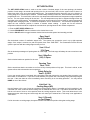
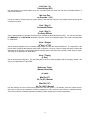
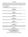
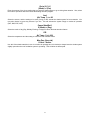
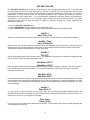
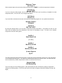
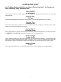
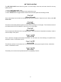
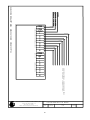
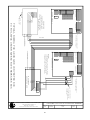
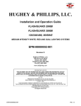
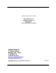
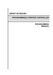
MICRO GROW
GREENHOUSE SYSTEMS, INC
26111 YNEZ RD., SUITE C-4, TEMECULA, CA 92591 PHONE (909)-296-3340 FAX (909)-296-3350
Revision 1.2, 12-17-01
Procom Greenhouse
Control System
INSTALLATION PROCEDURES
GROWMASTER SERIES OF CONTROLLERS
PANEL MOUNTING
Mount the control panel in an accessible location. Make sure that the location is free of vibration and in close
proximity to the devices being controlled. Always consider voltage drop of electrical current when locating the
control panel. Securely mount the panel.
SWITCHING CONTACTORS AND RELAYS
The control panel will operate the greenhouse equipment via load contactors and load relays. ALL RELAYS
AND LOAD CONTACTORS USED MUST HAVE A SURGE SUPPRESSOR INSTALLED ACROSS THE
COIL OF THE RELAY OR LOAD CONTACTOR. These surge suppressors are readily available from Micro
Grow Greenhouse Systems, Inc. All load contactors and relays are also readily available from Micro Grow
Greenhouse Systems, Inc. To decide which to use, follow this guide:
LOAD CONTACTORS: Exhaust fans, pad pumps, horizontal air flow fans, heating pumps, fan jets, large
heaters, crop lighting, and all other larger electrical loads over 1/6 H.P.
LOAD RELAYS: Signal switching such as the small control lines for gas fired heaters, control lines for vent
and shade system controls, small loads such as motorized shutters, other loads up to 1/6 H.P.
CUSTOM CONTACTOR AND RELAY PANEL AVAILABLE A custom built load contactor and load relay
panel is available from Micro Grow Greenhouse Systems, Inc. This panel will contain all of the required
switching apparatus for your project, as well as a correctly sized machine tool transformer. Contact Micro
Grow Greenhouse Systems, Inc. for pricing and availability.
TRANSFORMERS
A 24 VAC transformer will power the control panel. It is important to use a MACHINE TOOL type. A Machine
Tool Transformer is a heavy-duty variety that will allow for high inrush currents that are associated with the use
of load contactors and relays. Micro Grow Greenhouse Systems, Inc. stocks these types of transformers.
Use no smaller than a 50 VA Machine Tool Transformer. For a system that has more than three load
contactors connected, use a 100 VA Machine Tool Transformer.
ELECTRICAL CIRCUITS
The electrical circuit that feeds the machine tool transformer must have no other loads connected to it. This
will prevent damaging surges from other related electrical devices. Follow all local and national codes in the
connection of all of the greenhouse equipment. Always allow for voltage drop conditions. Always consider
that the greenhouse is a wet environment. Always follow the code rulings for disconnect switches and
overcurrent devices on greenhouse equipment. USE A QUALIFIED AND LICENSED ELECTRICIAN AT ALL
TIMES.
1
WIRING METHODS
Always use stranded wire when connecting cables or conductors to the actual circuit board of the control
panel. This will allow flexibility. Use no smaller than #18 gauge stranded wire for all outputs. Use no smaller
than the recommended wire size of stranded cable for inputs, generally #22 gauge.
SENSOR CONDUCTORS: Route sensor conductors separately from control conductors. This is very
important so as to reduce electrical interference. Never route sensor conductors in conduits used for other
voltages. This is in violation of the electrical code and will cause dangerous interference to the control system.
Always locate the actual sensor in the center of the range that is being controlled for accurate readings. Do
not allow the sensor to come in contact with any greenhouse structure member such as a post that would give
off any radiated heat and cause a false temperature reading. Do not locate the sensor where a particular
piece of equipment would cause false readings, such as a heater blowing directly on the sensor. Mount all
wind/rain sensor is a clear area, free of any wind obstructions.
CONTROL CONDUCTORS: Route all control conductors separately from sensor conductors. This is very
important so as to reduce electrical interference. Control conductors maybe routed in conduits that contain
other power system wiring only if the insulation material on the conductors is the same as the power system
wiring. Consult the national electrical code or local codes if in doubt about the insulation ratings of the wire in
use. Remember; always use a qualified and licensed electrician.
VENT SYSTEMS, SHADE SYSTEMS, ROLL UP CURTAINS
When connecting a vent system, shade system, or roll up curtain ventilation system to the control panel, you
must use a separate control box designed for that particular vent or shade system. These are readily
available from Micro Grow Greenhouse Systems, Inc. Generally these separate control boxes feature
overcurrent protection for the particular motor on the vent or shade system, provisions for direct limit switch
connections, and a manual means of operating the vent or shade system independent of the main control
system. These separate control boxes will connect the main control system either directly through the outputs
of the control system, or they will require control relays for interconnection to the main control system. Consult
the individual instructions that come with the vent or shade controls for detailed information.
SYSTEM TESTING
It is always important to completely and fully test the electrical system by energizing circuits and verifying
equipment operations before automatically operating the equipment from the control panel. This would
include setting all of the vent and shade limit switches at the individual control panels.
2
GROWMASTER PROCOM
OPERATING INSTRUCTIONS
PROCOM SERIES
The PROCOM Series is a completely programmable greenhouse computer system. Any output may be
assigned to any input or function. The PROCOM is set up by Micro Grow Greenhouse Systems, Inc. and preprogrammed for the individual requirements of the control system in use.
PROGRAMMING LIGHTS
RUN - Indicates that the system is in the running mode.
SET PROGRAM-All temperatures, humidity levels, and other information are set here.
SET REPORTS-This will enable the REPORT feature of the Growmaster.
SET CALIBRATION-This will put the Growmaster in the calibration mode.
SET SYSTEM-Set the clock, set the day, midday, evening, and night criteria here. Set system identifications.
SET COOLING-Set the criteria for all of the maintained cooling outputs here.
SET HEATING-Set the criteria for all of the maintained heating outputs here.
SET VENTILATION-Set the criteria for all of the staged ventilation outputs here.
SET SHADING-Set the criteria for all of the shading outputs here.
SET FOGGING-Set the criteria for all of the fogging outputs here.
SET HEAT VALVES-Set the criteria for all of the modulating heat valves here.
SET DEHUMIDIFY-Set the dehumidify functions here.
SET CROP LIGHTS-Set the criteria for all crop lighting outputs here.
SET CO2-Set the CO2 criteria here.
SET ALARMS-Set the alarm choices here.
SET OTHER-Other functions, consult Micro Grow.
3
PROGRAMMING SWITCHES
There are three main programming switches located on the Growmaster front panel. These are:
RUN-SET SWITCH
RUN-Puts the control in the RUN mode.
SET-Puts the control in the SET mode in order to set all functions as outlined on the programming lights.
PRIOR-NEXT SWITCH
PRIOR-Advances to the prior item in the menu.
NEXT-Advances to the next item in the menu.
VALUE UP-VALUE DOWN SWITCH
VALUE UP-Increases the value in the display.
VALUE DOWN-Decreases the value in the display.
(The VALUE switch is also used to toggle between
selected item choices available)
TO SET THE PROGRAMS
The SET PROGRAM mode allows the grower to set all of the temperatures, humidity levels, shading solar levels,
and other settings. In this mode the normal day to day settings will be entered. No details such as time delays,
differentials, etc. are entered here. Refer to the individual SET modes for the individual criteria settings.
The screen will display the first selected item to set the program on. The screen will also indicate by flashing
whether the setting will apply to DAY, MIDDAY, EVENING, or NIGHT.
1.
2.
3.
4.
5.
Enter the SET PROGRAM mode.
Use the PRIOR-NEXT switch to advance to the desired item to set.
Use the VALUE switch to increase or decrease the desired value.
Use the PRIOR-NEXT switch to advance to the next desired item to set.
Return to the RUN mode.
Cooling 1 DAY
(80) 80 80 80
Set the desired value for the flashing segment. Set for DAY, MID (Midday), EVE (Evening) and NGT (Night). You
may disable the MID AND EVE settings in the SET SYSTEM mode if desired.
As you continue to toggle through the display in the SET PROGRAM mode, all pre-programmed features will
come up for similar settings. Set all of these in the same manner as above. You may then return to the run mode,
or if no switches are used after a short timed period, the Procom will automatically return to the run mode.
The items that can be set in the SET PROGRAM mode:
1.
2.
3.
4.
5.
6.
7.
Cooling and heating temperatures.
Ventilation temperatures.
Fog temperature and humidity.
Hot water zone temperatures,
Shade system light intensity.
Dehumidify humidity levels.
CO2 levels.
4
RUN REPORTS
The RUN REPORTS mode allows the grower to run selected reports on the sensor history.
1. Enter the RUN REPORTS mode.
2. Use the PRIOR-NEXT switch to advance to the desired report.
3. Continue to use the PRIOR-NEXT switch to advance and view reports.
Display Report
(Inside)
Select the desired report for display.
CALIBRATE
The CALIBRATE mode is used in order to calibrate all of the sensor readings. It is also used to calibrate the vent
and shade positions in the event that they have been moved manually and do not match the GROWMASTER
display as to the percentage opening. Calibration always should be done with a good thermostat or humidity
indicator, and when conditions have been calm for a period of time. Late afternoon or early morning is best,
without solar influence.
1. Enter the CALIBRATE mode.
2. Use the PRIOR-NEXT switch to advance to the desired item to calibrate.
3. Use the VALUE switch to increase or decrease the display reading.
Calibrate:
Air Temp 1 80o F
Set the desired value. The calibration procedure should be done with a reliable thermometer, out of direct solar
influence when calibrating temperatures. Use a wet and dry bulb to calculate humidity.
You may also calibrate any ventilation or shade position in this mode. Advance to the desired vent or shade
position in the CALIBRATE mode, and enter the actual position of the vent or shade system. The Procom will then
move the vent or shade to the correct position.
Calibrate:
Vent 1 50%
5
GROWMASTER PROCOM SET UP
SET SYSTEM
The SET SYSTEM mode is used to set the system clock and date, manually view the system's sunrise and sunset
times, adjust the system photocell, and to set the custom identification that will appear on the display during the
run mode. Also, this mode is used to determine the times of day, either by sunrise, sunset, clock, or a
combination of means, by which the four separate settings will apply. The four settings are listed as DAY,
MIDDAY, EVENING, and NIGHT. In addition, the input and output configurations that have been pre-programmed
into the PROCOM series control can be reviewed here. The air circulation functions may be defined in this mode.
Finally, the remote ID code for use with the GROWLINK PC communications program is set here.
1. Enter the SET SYSTEM mode.
2. Use the PRIOR-NEXT switch to advance to the desired item to set.
3. Use the VALUE switch to increase or decrease the display reading. Also use this switch to toggle between
desired choices that the system has internally provided.
Set Clk (12:00) PM
Mon 01/ 02/ 94
Set the correct time and date.
Sunrise 7:00 AM
Sunset 8:00 PM
These are the current values that the control is sensing for sunrise and sunset. There is no need to change these
values; the control will update automatically.
Light Sensor
(Med) Sensitivity
Select the desired sensitivity for the photocell. The photocell will detect sunlight and use this information to put the
control in the evening or night modes. You may also elect to have the Procom enter the evening or night modes
before or after sunset. Also, the Procom can enter the day modes before or after sunrise.
Custom System ID
(OFF)
By changing this to PROGRAM, you may enter a custom ID that will appear on the screen when the system is
running. This may include the name of the range, or other information. If PROGRAM is selected, then use the
VALUE switch to select the desired alphanumeric information, and the PRIOR/NEXT switch to advance to the next
digit. A blank space, punctuation marks, and numerals may also be selected if desired.
DAY Mode
(At Sunrise)
Select how the four modes of operation, DAY, MID, EVE, NGT will be affected. You may choose a switching
action AT SUNRISE, PRE-SUNRISE (Sunset for EVE and NGT) or TIMED. You may also choose NOT IN USE to
disable EVE and MID if desired.
Review I/O
Assignments? (N)
Use this selection to review the assigned inputs and outputs for your system. You may not change them here,
only review them. To change the assignments, please contact Micro Grow for a specific code to enter into your
system to enable you to change the configuration.
6
Remote ID Code:
(0)
Not applicable if not using the GROWLINK program. Set the ID code here for the Growlink remote PC program
available from Micro Grow Greenhouse Systems Inc. Every ID code must be different for each Procom.
Link Air 1
To Output (1)
Select the output that the Air Circulation output will be linked to. You may select any stage of operation; even a
vent or shade position may be selected. If a vent or shade output is selected, the Procom will ask for a position for
that device to energize or de-energize the air circulation output. You may also link the air circulation to one or two
particular sensors.
Air 1 On if
Output is (ON)
OR
(IF VENT OR SHADE POSITION IS SELECTED)
Air 1 On if
Output is (<=) (CL)
Select when to turn on the Air Circulation output, or, if the output is a vent or other staged device, set the position
of operation desired to energize the air circulation output.
Link Air 1 To
(1) Sensor
Enter the selected sensor here to link the air circulation stage to. If no sensor is desired, select “No Sensors” from
the menu. If “No Sensors” is selected, the air circulation will only look at the previously selected output link. If a
sensor however is selected, enter the next screen information as:
Turn On Air if
(Sensor Selection) >=(70)
7
SET COOLING
The SET COOLING mode will be used to set the desired cooling stage temperature separations and differentials.
The internal time delays that will prevent rapid cycling are also set here. Also, this mode is used to determine if
any of the cooling stages will be activated during the dehumidify functions of the system. You may choose either
the immediate dehumidify function, or the delayed dehumidify function. You may adjust the cooling temperatures
throughout the day based on the intensity of the solar level. You also can link any cooling selection to another
output in order to completely or partially disable that set of cooling when the other output, including a vent or a
shade system, is active. The temperature ramping time can be entered here. This is the amount of time required
to change the temperature from one mode to the next.
1. Enter the SET COOLING mode.
2. Use the PRIOR-NEXT switch to advance to the desired item to set.
3. Use the VALUE switch to toggle between desired choices that the system has internally provided.
Cooling 1 Stages
(2o Sep.) 2o Dif.
Set the desired separation of the cooling stages here, and also the desired differential. The separation is the total
number of degrees that separate each stage of operation. Once an output or a stage has been activated, the
differential is the amount of temperature change required that will cancel the operation of that stage or output.
Cooling 1 Timing
(2 Sec.)
Set the desired time delay here. The time delay will be active on both energizing and de-energizing stages.
Cooling 1 Stg (1)
On Immed Dehum
Cooling 1 Stg (1)
On Delay Dehum
Set the desired stages of operation here that will be activated by the dehumidify functions. You may choose either
the IMMEDIATE or the DELAYED dehumidify functions for a particular stage.
Cooling 1
Solar Adjust? (N)
(IF YES)
Cooling 1
Min Sol (0) K-LUX
Cooling 1
Min Sol (100) K-LUX
(Lower) Setpoint
By 0°F
8
The Solar Adjustment feature allows the grower to adjust the cooling temperature setpoint up or down depending on how
intense the solar level is. The solar level is monitore4d by the K-Lux sensor if used. The solar level can also be monitored by
a PAR or Pyranometer sensor if connected to the Procom.
Setpoint Ramp
(30) Minutes/Deg
This is the ramp time of the heating system. Enter the desired time that it will take the system to implement a
change in the heating setting. The Procom will use this time when changing modes (Day, Midday, Evening, and
Night).
Link Cooling 1
To (Output Selection)
(IF LINKED)
Cooling 1 (Max) 0
If Output (Selection) ON
You may use this setting to link a cooling selection to any particular output. This also includes vents or shade
systems. When this feature is used, the cooling stage(s) will either turn off completely (0 selection), or turn off
partially (maximum stage selection) when a particular output, shade, or vent is active.
9
SET HEATING
The SET HEATING mode will be used to set the desired Heating stage temperature separations and differentials.
The internal time delays that will prevent rapid cycling are also set here. Also, this mode is used to determine if
any of the Heating stages will be activated during the dehumidify functions of the system. You may choose either
the immediate dehumidify function, or the delayed dehumidify function. You may adjust the Heating temperatures
throughout the day based on the intensity of the solar level. You also can link any Heating selection to another
output in order to completely or partially disable that set of Heating when the other output, including a vent or a
shade system, is active. The temperature ramping time can be entered here. This is the amount of time required
to change the temperature from one mode to the next.
1. Enter the SET HEATING mode.
2. Use the PRIOR-NEXT switch to advance to the desired item to set.
3. Use the VALUE switch to toggle between desired choices that the system has internally provided.
Heating 1 Stages
(2o Sep.) 2o Dif.
Set the desired separation of the Heating stages here, and also the desired differential. The separation is the total
number of degrees that separate each stage of operation. Once an output or a stage has been activated, the
differential is the amount of temperature change required that will cancel the operation of that stage or output.
Heating 1 Timing
(2 Sec.)
Set the desired time delay here. The time delay will be active on both energizing and de-energizing stages.
Heating 1 Stg (1)
On Immed Dehum
Heating 1 Stg (1)
On Delay Dehum
Set the desired stages of operation here that will be activated by the dehumidify functions. You may choose either
the IMMEDIATE or the DELAYED dehumidify functions for a particular stage.
Heating 1
Solar Adjust? (N)
(IF YES)
Heating 1
Min Sol (0) K-LUX
Heating 1
Min Sol (100) K-LUX
(Lower) Setpoint
By 0°F
10
The Solar Adjustment feature allows the grower to adjust the cooling temperature setpoint up or down depending on how
intense the solar level is. The solar level is monitore4d by the K-Lux sensor if used. The solar level can also be monitored by
a PAR or Pyranometer sensor if connected to the Procom.
Setpoint Ramp
(30) Minutes/Deg
This is the ramp time of the heating system. Enter the desired time that it will take the system to implement a
change in the heating setting. The Procom will use this time when changing modes (Day, Midday, Evening, and
Night).
Link Heating 1
To (Output Selection)
(IF LINKED)
Heating 1 (Max) 0
If Output (Selection) ON
You may use this setting to link a Heating selection to any particular output. This also includes vents or shade
systems. When this feature is used, the Heating stage(s) will either turn off completely (0 selection), or turn off
partially (maximum stage selection) when a particular output, shade, or vent is active.
11
SET VENTILATION
The SET VENTILATION mode is used to set the number of desired stages of the vent openings, the desired
position of each stage, the actual total opening time for the vent itself, and to let the system know if there is a
safety time delay in the vent control panel being used. The programming also allows the vent to be linked to a
cooling stage or to override input if desired. The dehumidify functions of the vent, both immediate and timed, are
programmed here. This mode also is where the vent temperature differentials and temperature stage separations
are set. The vent system timing will be set here. The vent temperature may also be adjusted throughout the day
according to the solar intensity. An adjustable ramp time can be entered in order to allow for gradual temperature
changes when changing modes. A reference temperature can be entered here. The reference temperature will
adjust the vent maximum position in relation to another sensor reading. A typical use for the reference
temperature selection would be to adjust the vent maximum opening based on the outdoor temperature.
1. Enter the SET VENTILATION mode.
2. Use the PRIOR-NEXT switch to advance to the desired item to set.
3. Use the VALUE switch to toggle between desired choices that the system has internally provided.
Open Vent 1
In (4) Positions
Set the desired number of ventilation stages here. The system can operate the vent in up to eight separate
stages. If the output is connect to a pad vent system, then enter “PAD VENT”. The Growmaster Procom will now
open the pad vent with the cooling stages as they turn on.
Vent 1 Pos 1
10% Open
Set the desired percentages of opening here for each stage. The final stage will always be set to maximum vent
position.
Vent 1 Max Pos
(100) % Open
Set the desired maximum position for the vent.
Opening Time
Vent 1 3:00
Set the actual time that the vent takes to run from its fully closed position to fully open. This time is critical, as the
system will use this to determine correct openings.
Safety Delay for
Vent 1 (5) SEC
If your vent control system is equipped with a time delay relay that protects the vent against false reversals, enter
the number of seconds here. If you are in doubt whether your system has a time delay, simply manually energize
the vent. If the vent starts to move immediately, there most likely is no time delay protection. You may choose
NONE as one of the choices.
Link Vent 1 to
Cooling Stage (NO)
Use this feature to link a set of vents to a particular cooling stage if desired. A possible use for this would be in the
event that roof vents, as well as active cooling such as exhaust fans are in use. This feature will allow the user to
link the roof vents to close to a low position when the cooling stages are active. This would allow the air to be
drawn across the entire range and not through the roof vents by the exhaust fans. This setup is not applicable to
“PAD VENT”.
Vent 1 (Closed)
on Cool Stage 1
If a link is made to a cooling stage, the system will then ask what vent position during that cooling stage.
12
Link Vent 1 to
Override Inp (NO)
Use this setting if any override inputs are in use. Override inputs can come from the use of a Weather Station, or
other external device.
Mx Vent Pos
on Override 1 (CL)
If a link is made to override input, the system will then ask what the maximum vent position should be during that
override input period.
Vent 1 Stg (1)
On Immed Dehum
Vent 1 Stg (1)
On Delay Dehum
Set the desired stages of operation here that will be activated by the dehumidify functions. You may choose either
the IMMEDIATE or the DELAYED dehumidify functions, or both, for a particular stage. This setup is not applicable
to “PAD VENT”.
Vent 1 Stages
o
o
(2 Sep.) 2 Dif.
Set the desired separation of the ventilation stages here, and also the desired differential. The separation is the
total number of degrees that separate each stage of operation. Once an output or a stage has been activated the
differential is the amount of temperature change required that the will cancel the operation of that stage or output.
This setup is not applicable to “PAD VENT”.
Vent 1 Timing
(2 Sec.)
Set the desired time delay here. The time delay will be active on both energizing and de-energizing stages. This
setup is not applicable to “PAD VENT”.
Reference Temp:
(Sensor Selection)
(IF USED)
o
Min Ref (0 )
Go To (0%) Normal
o
Max Ref (70 )
Go To (100%) Normal
Use this selection to enter a reference temperature for the vent system. For example, select the outdoor sensor,
then enter a minimum and maximum reference temperature, and a minimum and maximum ventilation position.
The Procom will then constantly adjust the ventilation position based on the outdoor temperature.
13
SET SHADING
The SET SHADING mode will determine the total number of shade opening stages, the system timing for the
shade system, the solar level differential, and a maximum closed position for the shade system. The actual total
opening time for the shade system itself is entered here, and information as to a safety delay that may be present
in the actual shade control panel being used is also entered here. The heat retention feature of the shade system
can be programmed in this mode. You may also program the shade system to automatically back off if a roof vent
is active to allow increased airflow.
1. Enter the SET SHADING mode.
2. Use the PRIOR-NEXT switch to advance to the desired item to set.
3. Use the VALUE switch to toggle between desired choices that the system has internally provided.
Close Shade 1
in (4) Positions
Set the desired number of stages here for the shade system. If you are only using one output (fully cover) to close
your shade system in only one position, you may select “1 Pos, 1 output”.
Shade 1
Delay (5 Min.)
This will be the time delay that the system must see in order to move the shade system covered or uncovered.
This will be the amount of time that the solar level must maintain in order to cause movement.
Shade 1
Diff. (40) K-LUX
This is the differential of the shading system. This is the amount of solar light that is necessary to start opening
the shade system back up when the solar level decreases.
Shade 1
Max (100%) Closed
Use this setting if it is desired not to have the shade system close to 100% at any time. Use this if the shade
materials do not allow air passage and it is desired to always leave the shade system slightly open.
Shade 1
Close Time 3:00
Enter the actual time that it takes the shade system to go from a fully open position, to a fully closed position. This
is critical as the computer will use this time to determine the shade position.
Shade 1
Safety Delay (5) Sec
If your shade control system is equipped with a time delay relay that protects the vent against false reversals, enter
the number of seconds here. If you are in doubt whether your system has a time delay, simply manually energize
the shade system. If the shade system starts to move immediately, there most likely is no time delay protection.
You may choose NONE as one of the choices.
Shade 1
Heat Ret 1 (Disabled)
The shade system operation offers a heat retention feature. It is possible to use the shade system as an energy
curtain. If you choose to ENABLE this, you may then select the following choices:
1. Activate the Heat Retention Feature by a mode
of operation (EVE, NGT, etc.)
2. Activate the Heat Retention Feature if a sensor
is below or above a particular setting.
You may cancel the heat retention feature based also on the above criteria.
(There are two separate heat retention programs for the shade system)
14
Go to (0) % if
(Mode) = (Eve)
Enter the percent of the close position that you want the shade system to go to during heat retention. Also, select
the mode of operation desired to initiate the heating retention program.
And
(Air Temp 1) >= 80
Select the sensor, and the setting to be used (if any) to also activate the shade system for heat retention. You
may also choose to ignore any sensors if you like. This will activate the system simply on modes of operation
(DAY, MID, EVE, NGT)
Cancel HeatRet 1
If (Mode) = (Day)
Select the mode of day (Day, Midday, Evening, or Night) to cancel the heat retention feature.
OR
Air Temp 1 (<=) (60)
Select the temperature and the setting to cancel the heat retention mode.
Max Pos (Uncov’d)
If Vent 1 Active
Use this if the shade materials in use do not allow air passage and it is desired to always leave the shade system
slightly open when the roof ventilation system is operating. This will allow an airflow path.
15
SET FOGGING
The SET FOGGING mode is used to set the temperature and humidity differentials and the system timing for the
fogging output. The grower can also select if the fogging system should be maintained on or pulsed in this mode.
1. Enter the SET FOGGING mode.
2. Use the PRIOR-NEXT switch to advance to the desired item to set.
3. Use the VALUE switch to toggle between desired choices that the system has internally provided.
Fog 1 Diff.
o
(2) Temp 2% RH
Set the desired differentials for the temperature and the humidity settings for the fogging stage. The differential is
the amount of temperature decrease or humidity increase that the sensor must see before turning off the fogging
stage.
Fog 1 Timing
(2 Sec.)
Set the desired time delay here. The time delay will be active on both energizing and de-energizing stages.
Fog 1
(Maintained)
Fogging output may be commanded in two way, maintained or pulse. Maintained will turn on the output till the
humidity increases into the controlling band. Pulsed will allow the grower to enter the run and wait time to more
slowly increase the humidity level.
(IF PULSED SELECTED)
Fog 1 On
(2 Sec.)
Select the desired running time for the fogging system.
Fog 1 Off
(2 Sec.)
Select the desired waiting time for the fogging system.
16
SET HEAT VALVES
The SET HEAT VALVES mode is used to set the criteria for any modulating heat valves in use. In the event that
hot water valves are in use, the total opening time is set here. In addition, the run and wait times for the valves,
the hot water differential, and the minimum and maximum hot water temperatures are entered here. If a reference
temperature is being used to control the hot water temperature, the minimum and maximum reference
temperatures are also entered here. If a zone temperature activates the hot water system, the differential is
entered here. If a zone pump is in use, the system timing for that zone pump is also entered here. If a pulsed
opening hot water system is used the number of stages, the positions, opening time, delays, separation and
differentials is set here.
1. Enter the SET HEAT VALVES mode.
2. Use the PRIOR-NEXT switch to advance to the desired item to set.
3. Use the VALUE switch to toggle between desired choices that the system has internally provided.
Hot Wtr 1
Open Time (1:00)
Set the time for the valve to travel from fully open to fully closed. You will need to time the valve for operation.
Hot Wtr 1 Time
Run (10) Wait (30)
Set the desired run and wait times for the hot water valve. The PROCOM will use these times to pulse the valve by
applying the run time and then waiting for the duration of the programmed wait time before pulsing it open again.
These times will apply to either opening or closing of the valve.
Hot Wtr 1
o
Dif. (2) F
Set the desired differential of the hot water valves. The differential is the amount of temperature change that the
sensor must see before operating the hot water valve.
o
Min Water (100) F
o
Max Water (180) F
Enter the minimum and maximum water temperatures that you want the system to maintain. The control will then
try to maintain these “target” temperatures. If no reference temperature is being used, only enter a minimum
temperature setting here.
o
Min Refer (40) F
o
Max Refer (60) F
If a reference temperature is being used, enter the minimum and maximum reference temperature here. The heat
valve program can use a reference temperature such as a zone air temperature, or outdoor temperature to control
the heat valve. The PROCOM will automatically calculate the temperature differences and proportion the heat
valve accordingly.
Hot Wtr 1
o
Zone Dif (4) F
If a zone pump is being used with your hot water valve, set the desired temperature differential here. The
differential is the amount of temperature rise that the zone sensor must see before turning off the zone pump. If a
zone pump is not is use, you may ignore this setting.
Zone Pump
Timing (2) Sec.
If a zone pump is being used set the desired time delay here. The time delay will be active on both energizing and
de-energizing the zone pump.
17
Reference Temp:
(Air Temp 1)
Set the desired input to be used as the reference temperature or NONE if no reference temperature is desired.
If CO2 Active
o
Min Wtr 120 F
If you are using the CO2 program, the hot water valve may be driven open by entering a separate hot water
temperature here. If CO2 is not in use, disregard this feature.
Activate on
Dehum? (Y)
If you would like to activate the hot water valve when the dehumidify program is in use, please enter that here.
Standby Feature?
(Enabled)
Activate if
o
Wtr Tmp <=80 F
By using the standby feature, you may enter a minimum hot water temperature. If this feature is active, the hot
water valve will always keep this temperature even when not attempting to heat. This will be the “standby”
temperature of the hot water system.
Hot Wtr 1
Solar Adjust? (N)
(IF YES)
Hot Wtr 1
Min Sol (0) K-LUX
Hot Wtr 1
Min Sol (100) K-LUX
(Lower) Setpoint
By 0°F
The Solar Adjustment feature allows the grower to adjust the cooling temperature setpoint up or down depending
on how intense the solar level is. The solar level is monitore4d by the K-Lux sensor if used. The solar level can
also be monitored by a PAR or Pyranometer sensor if connected to the Procom.
Setpoint Ramp
(30) Minutes/Deg
This is the ramp time of the heating system. Enter the desired time that it will take the system to implement a
change in the heating setting. The Procom will use this time when changing modes (Day, Midday, Evening, and
Night).
18
PULSED HEATING VALVES
Use The Below Settings Only if You are Using a “Pulsed Heat Valve” The Pulsed Heat
Valve is Different Than a “Hot Water Valve”
Open Heating 2
In (4) Positions
Set the desired number of heating stages here. The system can operate the proportional valve in up to eight
separate stages.
Heating 2 Pos 1
10% Open
Set the desired percentages of opening here for each stage. The final stage will always be set to 100%.
Opening Time
Heating 2 3:00
Set the actual time that the valve takes to run from its fully closed position to fully open. This time is critical, as the
system will use this to determine correct openings.
Heating 2 Stg (1)
On Immed Dehum
Set the desired stages of operation here that will be activated by the dehumidify functions. You may choose either
the IMMEDIATE or the DELAYED dehumidify functions, or both for a particular stage.
Heating 2 Stages
(2o Sep.) 2o Dif.
Set the desired separation of the heat valve stages here, and also the desired differential. The separation is the
total number of degrees that separate each stage of operation. Once an output or a stage has been activated the
differential is the amount of temperature change required that will cancel the operation of that stage or output.
Heating 2 Timing
(2 Sec.)
Set the desired time delay here. The time delay will be active on both energizing and de-energizing stages.
19
SET DEHUMIDIFY
The SET DEHUMIDIFY mode is used to enable or to disable the dehumidify functions of the control. The run time
of the immediate and the delayed dehumidify functions are set here. The repeat time of the dehumidify feature is
set here. The dehumidify differential, and the maximum heat loss and gain for the dehumidify mode are also
entered here.
1. Enter the SET DEHUMIDIFY mode.
2. Use the PRIOR-NEXT switch to advance to the desired item to set.
3. Use the VALUE switch to toggle between desired choices that the system has internally provided.
Dehum 1
(Disabled)
You may select how to disable the dehumidify feature. Dehumidify may be disabled upon an override input. The
dehumidify feature can be disabled all together if desired.
Dehum 1 Imm
Run time (10) Min
Enter the time to allow Immediate Dehumidify to run.
Dehum 1 Dly
Run Time (10) Min
Enter the time to allow Delay Dehumidify to run.
If Dehum Fails
Rpeat in (2:00) H
Enter the time to repeat the dehumidify if unable to lower the humidity. If you would like the Procom to constantly
stay in the dehumidify mode if the humidity level is high, without an interruption, enter “Stay in Dly Mode”.
Dehum 1 Dif.
(2)% RH
Set the desired differential for dehumidify. The differential is the amount of humidity decrease that the sensor
must see before disabling dehumidify.
Disable Dehum if
o
below HtSP by (5)
Set the maximum heat loss below the normal heating set point temperature. This will disable any cooling stages
activated during dehumidify. This prevents too much heat loss in the range during dehumidify.
Disable Dehum if
o
above HtSP by (5)
Set the maximum heat gain above the normal heating set point temperature. This will disable any heating stages
activated during dehumidify. This prevents too much heat gain in the range during dehumidify.
20
SET CROP LIGHTING
The SET CROP LIGHT mode allows the grower to set time delays, solar levels, and other criteria for the crop
lighting outputs.
1. Enter the SET CROP LIGHT mode.
2. Use the PRIOR-NEXT switch to advance to the desired item to set.
3. Use the VALUE switch to toggle between desired choices that the system has internally provided.
Crop Lgt 1
(ON at All Levels)
Set the desired light level at which the crop lighting output should energized. If light level is not a factor, select ON
at All Levels.
Crop Lgt 1
Delay (5 Min.)
This will be the time delay that the system must see in order to energize or de-energize. This will be the amount of
time that the solar level must maintain in order to turn on or off the lights.
Crop Lgt 1
Diff. (3) KLUX
This is the light level differential of the crop lighting system. This is the amount of light that is necessary in order to
cause a change in the system.
Crop 1 1st ON
(At) 6:00 PM
This is when the crop light will be initially be activated. You can select one of the following: at a specified time,
after/before sunset, or after/before sunrise.
Crop 1 1st OFF
(At) 6:00 PM
This will be the off time. You can select one of the following: after running a pre-set period of time, after/before
sunset, or after/before sunrise.
Crop 1 2nd ON
(Not in Use)
This allows you to set the second operational time for crop lighting, if desired.
21
SET CO
2
2
2
2
All the desired CO settings will be made in the SET CO mode. Linking of CO to a Ventilation or Cooling output,
setting of differentials, and time delays.
2
1. Enter the SET CO mode.
2. Use the PRIOR-NEXT switch to advance to the desired item to set.
3. Use the VALUE switch to toggle between desired choices that the system has internally provided, or to increase
or decrease the desired display setting.
Link CO2 1 to:
(Desired Output)
2
If there is ventilation outputs or cooling stages on the Growmaster Procom, CO can be linked to them to reduce
2
the setpoint levels of C0 called for gradually.
(IF LINKED)
Reduce PPM (25%)
If Vent 1 >= 26%
Enter the percentage to reduce the ppm of CO2 setpoint, and the desired stage or vent position. The Growmaster
Procom has two setpoint reduction stages for CO2. If CO2 is linked to a ventilation output, then you will be able to
enter the vent percentage open to start the reduced setpoints. If CO2 is linked to a cooling output(s), then you will
be able to enter the cooling stage to start the reduced setpoints.
Reduce PPM 50%
If Vent 1 >= (50%)
Enter the percentage and stage for the second adjustment desired.
Cancel CO2 1
If Vent 1 >= (75)%
Enter the ventilation position or desired stage to cancel the CO2 program. The Growmaster Procom will restart the
CO2 program once the ventilation position or cooling stage has been lowered or turned off.
CO2 1 Diff
(50) PPM
This is the PPM of CO2 differential of the CO2 system. This is the change in the PPM of CO2 that is necessary to
cause a change in the system.
CO2 1 Delay
(30 Sec.)
2
This will be the time delay that the system must see to energize or de-energize the CO output.
22
SET ALARM
All of the desired alarm settings will be made in the SET ALARM mode. Set the high and low alarm settings for
the individual sensors.
1. Enter the SET ALARM mode.
2. Use the PRIOR-NEXT switch to advance to the desired item to set.
3. Use the VALUE switch to toggle between desired choices that the system has internally provided, or to increase
or decrease the desired display setting.
Air Temp 1 Alarm
Enabled? (Yes)
Air Temp 1 Alarm
LO: (0) HI: 120
Enter the set points to activate the alarm output. Only temperatures and humidifies will have an alarm feature.
TO CLEAR AN ACTIVE ALARM:
1.
2.
3.
Remedy the alarm condition.
Enter the SET ALARM mode.
Return to the RUN mode.
23
OUTPUT #1
OUTPUT #2
OUTPUT #3
OUTPUT #4
OUTPUT #5
OUTPUT #6
OUTPUT #7
OUTPUT #8
OUTPUT #9
OUTPUT #10
OUTPUT #11
OUTPUT #12
24 VAC POW ER INPUT
24 VAC POW ER INPUT
FUSED 24 VAC
ALARM
SENSOR
RS 485
1
2
3
4
DIGITAL IN PUTS
SENSOR INPUT TERM IN AL STRIP
POW ER IN PUT AND
CONTROL OUTPUT STRIP
1
2
3
4
5
6
7
8
9
10
11
12
COM
AC IN
FUSED AC
1
2
3
4
TRANSFORM ER NOTE:
USE A M ACHINE TOOL VARIETY ONLY.
100 VA IS RECOM M ENDED.IF A SM ALLER
SIZED TRANSFORM ER IS USED,ADJUST
THE FUSE PROTECTION ACCORDINGLY.
(see fuse note)
FUSE NOTE:
IM PORTANT:DO NOT EXCEED 4 AM PS
FOR THE FUSE RATING W HEN USING
A 100 VA TRANSFORM ERD OR 2 AM PS
W HEN USING A 50 VA TRANSFORM ER.
USE A SLOW BLOW VARIETY.
OUTPUT NOTE:
THE CONTROL OUTPUTS ARE RATED AT
1 AM P EACH M AXIM UM .DO NOT EXCEED
THIS OR DAM AGE M AY RESULT.DO
NOT EXCEED 1 AM P FOR ANY SINGLE
OUPUT OR 4 AM PS TOTAL FOR ALL.
(2 AM PS TOTAL IF A 50 VA
TRANSFORM ER IS IN USE)
24
ALL CONNECTED 24 VAC LOAD RELAYS
AND CONTACTORS M UST HAVE A SURGE
PROTECTION DEVICE INSTALLED ACROSS
THE COILS. SURGE SUPPRESSION
DEVICES ARE AVAILABLE UPON REQUEST.
24 VAC
M ACH IN E TOOL
TRAN SFORM ER
24 VAC COM M ON
FOR ALL LOAD S
POW ER FAILURE
ALARM OUTPUT
ALL CORRECT LOAD CONTACTORS AND CONTROL RELAYS
ARE AVAILABLE FROM M ICROGROW GREENHOUSE SYSTEM S.
100VA M ACHINE TOOL TRANSFORM ERS ARE AVIALABLE FROM
M ICRO GROW GREENHOUSE SYSTEM S. SEE YOUR DISTRIBUTOR
OR CALL M ICRO GROW FOR REQUIRED CONNECTION DEVICES
AND ACCESSORIES.
GROW M ASTER PROCOM OUTPUTS
Drawn by
PRO C O M O UTPUTS
Date
Distributor
O rderID
GH
11/27/01
N/A
N/A
26111 Ynez Road,Suite C -4
Tem ecula,C A 92591
Phone 909.296.3340 Fax 909.296.3350
Project
M IC RO G RO W G REENHO USE SYSTEM S,INC .
COM
AC
1
1
2
2
3
3
4
4
FUSE
COM
COM
+5VDC
1
2
3
4
5
6
7
8
FUSED 24 VAC
24 VAC COM
OUTPUT #13
OUTPUT #14
OUTPUT #15
OUTPUT #16
OUTPUT #17
OUTPUT #18
CONTROL OUTPUT STRIPS
1
2
3
4
5
6
CONTROL OUTPUT STRIPS
1
2
3
4
5
6
RIBBON
CABLE
OUTPUT NOTE:
THE CONTROL OUTPUTS ARE RATED AT 1 AM P EACH
M AXIM UM .DO NOT EXECEED THIS OR DAM AGE M AY
RESULT.DO NOT EXCEED 1 AM P FOR ANY SINGLE
OUTPUT OR 4 AM PS TOTAL FOR ALL OUTPUTS.(2
AM PS TOTAL IF A 50 VA TRANSFORM ER IS IN USE)
25
ALL CON NECTED 24 VAC LOAD RELAYS
AN D CON TACTORS M UST HAVE A SURGE
PROTECTION D EVICE IN STALLED ACROSS
TH E COILS. SURGE SUPPRESSION
D EVICES ARE AVAILABLE UPON REQUEST.
FUSED 24 VAC
24 VAC COM
OUTPUT #19
OUTPUT #20
OUTPUT #21
OUTPUT #22
OUTPUT #23
OUTPUT #24
ALL CORRECT LOAD CON TACTORS AN D CON TROL RELAYS ARE AVAILABLE FROM M ICRO GROW GREEN H OUSE SYSTEM S.
100VA M ACH IN E TOOL TRAN SFORM ERS ARE AVAILABLE FROM M ICRO GROW GREEN H OUSE SYSTEM S.SEE YOUR
D ISTRIBUTOR OR CALL M ICRO GROW FOR REQUIRED CON N ECTION D EVICES AN D ACCESSORIES.
GROW M ASTER PROCOM EXPANSION M ODULE OUTPUTS
Drawn by
PRO C O M EXPANSIO N M O DULE O UTPUTS
Date
Distributor
O rderID
GH
11/27/01
N/A
N/A
26111 Ynez Road,Suite C-4
Tem ecula,C A 92591
Phone 909.296.3340 Fax 909.296.3350
Project
M IC RO G RO W G REENHO USE SYSTEM S,INC .
+5VDC
SENSOR COMMON
SENSOR COMMON
1
2
3
4
5
6
SEN SOR IN PUT TERM IN AL STRIP
7
8
GROW M ASTER PROCOM IN PUTS
COM
COM
+5VDC
1
2
3
4
5
6
7
8
SEN SOR
M IC RO G RO W G REENHO USE SYSTEM S,INC .
26111 Ynez Road,Suite C -4
Tem ecula,C A 92591
Phone 909.296.3340 Fax 909.296.3350
SEE IN D IVID UAL SEN SOR D RAW IN GS
FOR D ETAILED CON N ECTION S.
D IGITAL IN PUTS
COM
AC
1
1
2
2
3
3
4
4
Project
G RO W M ASTER PRO C O M INPUTS
Drawn by
Date
Distributor
O rderID
GH
11/27/01
N/A
N/A
26
VIO
RAIN H EATER
W IN D D IRECTION
GRY
FUSED 24 VAC
BLU
W HT
+5 VD C
OUTD OOR TEM P.
RED
YEL
W IN D SPEED
BLK
RAIN
GRN
W IN D SPEED
RAIN
N ORTH
W IN D D IRECTION
BLUE
OVERRID E 1
OVERRID E 2
OVERRID E 3
24 VAC COM M ON
SECURELY M OUN T TH E OUTD OOR
SEN SOR AT TH E H IGH EST UN OBSTRUCTED
POIN T ON TH E GREEN H OUSE.
GREEN
ORANGE
BLACK
GRAY
YELLOW
RED
W H ITE
D IGITAL OVERRID E
IN PUT STRIP
SENSOR INPUTS
TERM INAL STRIP
D IGITAL OVERRID E
IN PUT STRIP
D ATA
IN PUT STRIP
4
3
2
1
PROCOM /GROW COM
N OTE:
D ATA CABLE TO
OTH ER PROCOM S
& PC LOCATION .
TYPICAL ALL
PROCOM S AN D
W EATH ER STATION
27
KLUX
SEN SOR COM M ON
OBSERVE N ORTH POSITION IN G !
SEN SOR AC
RAIN
W IN D DIRECTION
W IN D SPEED
SOLAR KLUX
OUTDOOR TEM PERATURE
+5 VDC
SEN SOR COM M ON
SENSOR INPUTS
TERM INAL STRIP
D ATA
IN PUT STRIP
4
3
2
1
COM
AC
1
1
2
2
3
3
4
4
ALL W IRE CON N ECTION S ARE TO
BE M AD E AT TERM IN AL STRIPS
W ITH IN TH E CON TROLS. D O N OT
SPLICE W IRES.
Project
W EATHERM ASTER TO PRO C O M /G RO W C O M
M IC RO G RO W G REENHO USE SYSTEM S,INC .
OUTD OOR
TEM P.
TO W EATH ERM ASTER
SEN SOR IN PUTS
IN SID E W EATH ERM ASTER
10 CON D .
SH LD
RAIN H EATER
VIOLET
H EATER COM M ON
BROW N
W IN D 1
W IN D 2
W IN D 3
W IN D 4
RAIN
SOLAR
TEM PERATURE
1
2
3
4
1
2
3
4
5
6
7
8
9
10
11
12
COM
AC IN
FUSE AC
COM
COM
ORG
1 2 3 4 5 6 7 8 9 10
SOLAR KLUX
TYPICAL W EATH ERM ASTER
CON N ECTION TO PROCOM /GROW COM
1
2
3
4
1
2
3
4
5
6
7
8
9
10
11
12
COM
AC IN
FUSE AC
COM
COM
Drawn by
Date
Distributor
O rderID
GH
11/01/01
N/A
N/A
26111 Ynez Road,Suite C -4
Tem ecula,C A 92591
Phone 909.296.3340 Fax 909.296.3350
COM
AC
1
1
2
2
3
3
4
4
W EATH ERM ASTER
FUSE
+5 VDC
1
2
3
4
5
6
7
8
FUSE
+5 VDC
1
2
3
4
5
6
7
8
BRN
H EATER COM M ON
SEN SOR IN PUTS
OUTPUT
OUTPUT
OUTPUT
OUTPUT
OUTPUT
OUTPUT
OUTPUT
OUTPUT
OUTPUT
OUTPUT
OUTPUT
OUTPUT
#1
#2
#3
#4
#5
#6
#7
#8
#9
#10
#11
#12
4
3
2
1
D IGITAL OVERRID E
INPUT TERM IN AL STRIP
GREEN
W H ITE
BLACK
RED
OUTPUT
OUTPUT
OUTPUT
OUTPUT
OUTPUT
OUTPUT
OUTPUT
OUTPUT
OUTPUT
OUTPUT
OUTPUT
OUTPUT
SEN SOR IN PUTS
1
2
3
4
5
6
7
8
9
10
11
12
COM
AC IN
FUSED AC
1
2
3
4
#1
#2
#3
#4
#5
#6
#7
#8
#9
#10
#11
#12
4
3
2
1
GROW M ASTER 2
GREEN
W H ITE
BLACK
RED
D IGITAL OVERRID E
INPUT TERM IN AL STRIP
2 - 220 OHM RESISTORS TO BE
IN STALLED ON TH E FIN AL
GROW M ASTER IN LIN E ONLY.
28
1
2
3
4
5
6
7
8
9
10
11
12
GROW M ASTER 1
N/A
COM
AC
COM M UNICATION CABLE IS 22 AW G,
TW ISTED 2 PAIR IND IVIDUALLY
SHIELD ED D ATA CABLE.
O rderID
N/A
1
1
2
2
3
3
4
4
D ATA LIN E
GROW LIN K
CON VERTOR BOX
(LOCATED AT PC TERM INAL,
INCLUD ED W ITH GROW LINK
SOFTW ARE PACKAGE)
Distributor
11/28/01
COM
COM
+5 VDC
RED
BLACK
W H ITE
GREEN
SH IELD
W H ITE
GREEN
RED
BLACK
Date
GH
1
2
3
4
5
6
7
8
FUSE
COM
AC IN
FUSED AC
1
2
3
4
120 VAC POW ER
25 PIN D-SUB
PLUG TO PC
Drawn by
G RO W LINK C O NV.BO X TO M ULTIG RO W M ASTERS
26111 Ynez Road,Suite C -4
Tem ecula,C A 92591
Phone 909.296.3340 Fax 909.296.3350
Project
M IC RO G RO W G REENHO USE SYSTEM S,INC .
FUSE
COM
AC
1
1
2
2
3
3
4
4
LOG GND
TO+
TOFO+
FO-
TYPICAL W IRIN G FOR GROW LIN K
CON VERTOR BOX TO M ULTIPLE GROW M ASTERS
D ATA LIN E
COM
COM
+5 VDC
1
2
3
4
5
6
7
8
OUTPUT
OUTPUT
OUTPUT
OUTPUT
OUTPUT
OUTPUT
OUTPUT
OUTPUT
OUTPUT
OUTPUT
OUTPUT
OUTPUT
SEN SOR IN PUTS
1
2
3
4
5
6
7
8
9
10
11
12
COM
AC IN
FU SED AC
1
2
3
4
#1
#2
#3
#4
#5
#6
#7
#8
#9
#10
#11
#12
4
3
2
1
D IGITAL OVERRID E
IN PUT ST RIP
GROW M ASTER 1
GROW LIN K
CON VERTOR BOX
*** ALL SH IELD S TOGETH ER, BUT
D O N OT LAN D ON BOARD .
GREEN
W H ITE
BLACK
RED
OUTPUT
OUTPUT
OUTPUT
OUTPUT
OUTPUT
OUTPUT
OUTPUT
OUTPUT
OUTPUT
OUTPUT
OUTPUT
OUTPUT
SEN SOR IN PUTS
1
2
3
4
5
6
7
8
9
10
11
12
COM
AC IN
FU SED AC
1
2
3
4
#1
#2
#3
#4
#5
#6
#7
#8
#9
#10
#11
#12
D IGITAL OVERRID E
IN PUT ST RIP
4
3
2
1
N/A
*** ALL SH IELD S TOGETH ER, BUT
D O N OT LAN D ON BOARD .
GREEN
W H ITE
BLACK
RED
2 - 220 OHM RESISTORS
TO BE IN STALLED ON
TH E FIN AL GROW M ASTER
IN LIN E ONLY.
O rderID
N/A
1
1
2
2
3
3
4
4
GROW M ASTER 2
N OTE:
Distributor
11/28/01
COM
AC
COM M UN ICATION CABLE IS 22 AW G, TW ISTED
2 PAIR IN D IVID UALLY SH IELD ED D ATA CABLE.
BE SURE TO M AKE ALL CON N ECTION S AT
TERM IN AL BLOCKS & SPLICE ALL SH IELD S.
RED
BLACK
W H ITE
GREEN
M ULTIDROP
REPEATER BOX
Date
GH
COM
COM
+5 VD C
120 VAC POW ER
FOFO+
FH FH +
TH TH +
TOTO+
COM
1
1
2
2
3
3
4
4
(LOCATED AT PC TERM IN AL,
IN CLUD ED W ITH GROW LIN K
SOFTW ARE PACKAGE)
SH IELD
W H ITE
GREEN
RED
BLACK
120 VAC POW ER
29
FUSE
1
2
3
4
5
6
7
8
FUSE
1
2
3
4
5
6
7
8
25 PIN D -SUB
PLUG TO PC
Draw n by
G RO W LINK C O NV.BO X TO M ULTIG M 'S W /REPEATER
26111 Ynez Road,Suite C -4
Tem ecula,C A 92591
Phone 909.296.3340 Fax 909.296.3350
Project
M IC RO G RO W G REENHO USE SYSTEM S,INC .
COM
AC
TYPICAL W IRIN G FOR GROW LIN K CON VERTER BOX
TO M ULTIPLE GROW M ASTERS W ITH REPEATER BOX
D ATA LIN E
COM
COM
+5 VD C
FOFO+
TOTO+
LOG GN D
SEN SOR COM M ON
TEM PERATURE
BLACK
RED
AIR TEM PERATURE OR
OUTD OOR TEM PERATURE
SEN SOR
TO SENSOR
TERM IN AL
STRIP
GREEN
RED
W HITE
BLACK
TO SENSOR
TERM INAL
STRIP
W H ITE
BLACK
KLUX SEN SOR
KLUX SEN SOR
RED
SEN SOR COM M ON
+5VD C
24 VAC COM M ON
24 VAC POW ER
SENSOR COM M ON
+5 VDC
AIR TEM PERATURE
HUM IDITY
W HITE
BLUE
GREEN
RED
ORANGE OR BROW N
BLACK
ASPIRATED AIR TEM PERATURE
AN D H UM ID ITY SEN SOR
FROM
TRAN SFORM ER
ROUTE TO
SEN SOR IN PUT
TERM INALS
LOCATE SENSOR IN THE CENTER OF THE
CONTROLLED AREA,AT BEN CH OR CROP LEVEL,
AW AY FROM D IRECT CONTACT W ITH
GREEN HOUSE M ETAL POSTS AND M EM BERS.
30
LOCATE SENSOR IN THE CENTER OF THE
CONTROLLED AREA,AT BEN CH OR CROP LEVEL,
AW AY FROM D IRECT CONTACT W ITH
GREEN HOUSE M ETAL POSTS AND M EM BERS.
SENSOR COM M ON
+5 VDC
AIR TEM PERATURE
H UM ID ITY
N ON -ASPIRATED AIR
TEM PERATURE & H UM ID ITY
SEN SOR
TO SENSOR
TERM INAL
STRIP
LOCATE SENSOR IN THE CENTER OF THE
CONTROLLED AREA,AT BEN CH OR CROP LEVEL,
AW AY FROM D IRECT CONTACT W ITH
GREEN HOUSE M ETAL POSTS AND M EM BERS.
PROCOM SEN SORS
Drawn by
PRO C O M TEM PS & HUM IDITY & KLUX SENSO RS
Date
Distributor
O rderID
GH
11/29/01
N/A
N/A
26111 Ynez Road,Suite C -4
Tem ecula,C A 92591
Phone 909.296.3340 Fax 909.296.3350
Project
M IC RO G RO W G REENHO USE SYSTEM S,INC .
TO SEN SOR
TERM IN AL
STRIP
BLACK
RED
BLACK
RED
SOIL TEM PERATURE
SEN SOR
SEN SOR COM M ON
TEM PERATURE
+5 VD C
SOIL TEM P.
PROBE
ATTACH USIN G
M ETAL PIPE CLAM P
31
SEN SOR COM M ON
SOIL TEM PERATURE
TO SEN SOR
TERM IN AL
STRIP
2.8K OH M S 1%
AVAILABLE FROM
M ICRO GROW
H OT W ATER PIPE
TEM PERATURE SEN SOR
PROCOM SEN SORS
Drawn by
PRO C O M HO T W ATER & SO IL TEM P SENSO RS
Date
Distributor
O rderID
GH
11/29/01
N/A
N/A
26111 Ynez Road,Suite C -4
Tem ecula,C A 92591
Phone 909.296.3340 Fax 909.296.3350
Project
M IC RO G RO W G REENHO USE SYSTEM S,INC .
M OUNTING PLATE
SENSOR CONNECTIONS
TO CONTROL
DISPLAY
ENG ELHARD
8 7 6 5 4 3 2 1
ENG ELHARD
2 1
C02 SENSOR
INCREASE/DECREASE
SELECTION VALUE
**FOR EXTERNAL
CONNECTION OF
ALARM CONTACTS
**ALARM RELAY NOTE:
RELAY CONTACTS 1 Amp M AX.
ALARM SET TO 1000 PPM .
SEE M ANUFACTURER'S
INSTRUCTIONS TO CHANGE
FACTORY SETTINGS.
NOTE:
CUSTOM ER M UST ATTACH
RESISTOR IN PROCOM CONTROL
SPAN RESISTOR
221 OHM 1 %
SENSOR
RS 485
1
2
3
4
DIGITAL INPUTS
SENSOR IN PUT TERM IN AL STRIP
POW ER INPUT AND
CONTROL OUTPUT STRIP
1
2
3
4
5
6
7
8
9
10
11
12
COM
AC IN
FUSED AC
1
2
3
4
PROCOM
32
COM
AC
1
1
2
2
3
3
4
4
FUSE
COM
COM
+5VDC
1
2
3
4
5
6
7
8
C02 SENSOR
CLEAR - RESETS M ENU
CHANGE;RETURNS TO
NORM AL M ODE
ENTER - PRESS TO
LOCK VALUE
CO, /
1234 PPM
M ODE - TOGGLES
TO NEXT M ENU ITEM
0 - 2000 PPM
1 AM P M AXIM UM
+- 10 PPM
+- 1 PPM
18 - 30 VAC
4 - 20 mA
SPECIFICATIONS:
M EASUREM ENT RANGE
RELAY OUTPUT
SENSITIVITY
RESOLUTION
POW ER
OUTPUT RANGE
NOT USED
SIGNAL GROUND
4 - 20 mA OUTPUT
RELAY NORM CLOSED
RELAY COM M ON
RELAY NORM OPEN
NOT USED
NOT USED
ENGELHARD CO 2 SENSOR
Project
PRO CO M ENG ELHARD CO 2 SENSO R CO NNECTIO NS
M IC RO G RO W G REENHO USE SYSTEM S,INC .
Drawn by
Date
Distributor
O rderID
GH
11/29/01
N/A
N/A
26111 Ynez Road,Suite C -4
Tem ecula,C A 92591
Phone 909.296.3340 Fax 909.296.3350
24 VAC COM
24 VAC
ROUTE TO
PROCOM
INPUTS
SENSOR COM M ON
PYRA SENSOR
+5 VDC
JUM PER POSITION
(LI-200 SZ)
CUT OUT PULLUP RESISTOR FOR
PYRANOM ETER INPUT ON
GROW M ASTER PROCOM .
GND
SIG OUT
+5 VDC
RED
BLACK
(COAXIAL CABLE)
SHIELD
SIGNAL OUT
JUM PER POSITION
(+5VDC OUTPUT)
(2 CON DUCTOR CABLE)
LI-COR
PYRANOM ETER
33
SENSOR CONNECTIONS
TO PROCOM CONTROL
W HITE
BLACK
RED
SHLD/GND
SIG IN
EM E SYSTEM S
AM PLIFIER PCB
NOTE:LOCATE AM PLIFIER CIRCUIT BOARD
W ITHIN PROCOM ENCLOSURE.SECURELY
M OUNT TO BACK OF ENCLOSURE.
LI-COR PYRANOM ETER LI-200
Drawn by
PRO CO M LI-CO RE PYRANO M ETER LI-200 CO NN.
Date
Distributor
O rderID
GH
12/14/01
N/A
N/A
26111 Ynez Road,Suite C-4
Tem ecula,CA 92591
Phone 909.296.3340 Fax 909.296.3350
Project
M IC RO G RO W G REENHO USE SYSTEM S,INC .
ROUTE TO
PROCOM
IN PUTS
SEN SOR COM M ON
PAR SENSOR
+5 VDC
JUM PER POSITION
(LI-190 SZ)
CUT OUT PULLUP RESISTOR FOR
PYRAN OM ETER IN PUT ON
GROW M ASTER PROCOM .
GN D
SIG OUT
+5 VD C
RED
BLACK
(COAXIAL CABLE)
SH IELD
SIGN AL OUT
JUM PER POSITION
(+5VD C OUTPUT)
(2 CON D UCTOR CABLE)
LI-COR
PAR SEN SOR
34
SEN SOR CON N ECTION S
TO PROCOM CONTROL
W HITE
BLACK
RED
SH LD /GND
SIG IN
EM E SYSTEM S
AM PLIFIER PCB
N OTE: LOCATE AM PLIFIER CIRCUIT BOARD
W ITH IN PROCOM EN CLOSURE. SECURELY
M OUN T TO BACK OF EN CLOSURE.
LI-COR QUAN TUM PAR LI-190
Drawn by
PRO C O M LI-C O RE PAR LI-190 C O NNEC TIO NS
Date
Distributor
O rderID
GH
12/14/01
N/A
N/A
26111 Ynez Road,Suite C -4
Tem ecula,C A 92591
Phone 909.296.3340 Fax 909.296.3350
Project
M IC RO G RO W G REENHO USE SYSTEM S,INC .
OVERRID E 1
USE TH E SAM E CON FIGURATION FOR
OVERRID ES 2, 3 AN D 4. OVERRID E 4 CAN
ALSO BE USED AS PH OTOCELL IN PUT.
OVERRID E 3
OVERRID E 4 OR PH OTOCELL
FROM OVERRID E D EVICE SUCH AS
W EATH ERM ASTER - M AXIM UM IN PUT VOLTAGE
OF 24 VAC
OVERRID E 2
D IGITAL IN PUTS
RED
PRO C O M SENSO RS
Date
Distributor
O rderID
GH
12/14/01
N/A
N/A
TYPICAL OVERRID E IN PUT
SEN SOR
PH OTOCELL
BLACK
D IGITAL IN PUTS
35
SEN SOR IN PUT TERM IN AL STRIP
PH OTOCELL
PH OTOCELL COM M ON
SEN SOR
PROCOM SEN SORS
Drawn by
26111 Ynez Road,Suite C -4
Tem ecula,C A 92591
Phone 909.296.3340 Fax 909.296.3350
N OTE: TH IS IS N OT N ORM ALLY IN STALLED
W ITH ALL PROCOM UNITS. IF IN STALLED , IT
IS LOCATED AT TH E BOTTOM OF TH E BOX.
PHOTOCELL
SEN SOR IN PUT TERM IN AL STRIP
COM
COM
+5VCD
1
2
3
4
5
6
7
8
Project
M IC RO G RO W G REENHO USE SYSTEM S,INC .
COM
AC
1
1
2
2
3
3
4
4
COM
AC
1
1
2
2
3
3
4
4
COM
COM
+5VCD
1
2
3
4
5
6
7
8
T2
L2
T1
L1
8
4
14
12
5
1
13
9
C O NTAC TO R NO TES:
LINES O N L3,L2,L1
LO ADS O N T3,T2,T1
RELAY NO TES:
RELAYS ARE DPDT
14,13 .....24 VAC CO IL
12,9 .....C O M M O N TERM INALS
8,5
.....NO RM ALLY O PEN
TERM INALS
.....NO RM ALLY CLO SE
TERM INALS
4,1
36
T3
L3
SURG E PRO TEC TIO N DEVICE RATED FO R 24 VAC O PERATIO N.
PRO VIDED W ITH EAC H UNIT
INSTALLATIO N O F SURG E
PRO TEC TIO N DEVIC ES O N
LO AD C O NTAC TO RS AND
LO AD RELAYS
Drawn by
INSTALLATIO N O F SURG E PRO TECTIO N DEVIC ES
Date
Distributor
O rderID
GH
12/14/01
N/A
N/A
26111 Ynez Road,Suite C -4
Tem ecula,C A 92591
Phone 909.296.3340 Fax 909.296.3350
Project
M IC RO G RO W G REENHO USE SYSTEM S,INC .
TO OUTPUT TO
TURN ON D EVICE
TO TRAN SFORM ER
(COM M ON SID E)
LOAD #3
LOAD #2
LOAD #1
CIRCUIT #1
CIRCUIT #2
CIRCUIT #3
TO
M OTOR
TO LOAD
CEN TER
37
T3 T2 T1
L3 L2 L1
COIL
SURGE PROTECTION D EVICE RATED FOR 24 VAC OPERATION .
PROVID ED W ITH EACH UN IT
CON N ECTION OF LOAD S
TO A LOAD CON TACTOR.
FOR LOAD S OVER 10 AM PS
AN D LESS TH AN 30 AM PS
Drawn by
C O NNEC TIO N O F LO ADS TO A LO AD C O NTAC TO R
Date
Distributor
O rderID
GH
12/14/01
N/A
N/A
26111 Ynez Road,Suite C -4
Tem ecula,C A 92591
Phone 909.296.3340 Fax 909.296.3350
Project
M IC RO G RO W G REENHO USE SYSTEM S,INC .
H IGH -SPEED FAN
LOW -SPEED FAN
ROUTE TO
24 VAC COM M ON
ELECTRICAL
IN TERLOCK
8 N .O.
4 N .C.
5 N .O.
1 N .C.
CON T RO L RELAY, D PD T
COM 9
COM 12
ROUTE TO H IGH
SPEED OUTPUT
ROUTE TO LOW
SPEED OUTPUT
13
9
TW O SPEED FAN S
IN TERLOCK
TYPICAL CON N ECTION FOR 2 SPEED LOAD
CON TACTOR USED FOR 2 SPEED FAN S
14
12
L1
L2
L3
A-2
T3
COIL
T2
A-1
T1
3 POLE LOAD CON TACTOR
RELAY AN D LOAD CON TACTOR
N OTES
5
1
COIL
CO IL, 24 VAC
CO N T ACT RATIN G 30 AM PS IN D U CTIVE
LIN E VO LTAG E ON L1-L3
LOAD ON T1-T3
38
LOAD
LOAD
8
4
CO IL, 24 VAC
CO N T ACT RATIN G 10 AM PS
Drawn by
TYPIC AL C O NNEC TIO N FO R 2 SPEED LO AD C O NTAC TO R
Date
Distributor
O rderID
GH
12/17/01
N/A
N/A
26111 Ynez Road,Suite C -4
Tem ecula,C A 92591
Phone 909.296.3340 Fax 909.296.3350
Project
M IC RO G RO W G REENHO USE SYSTEM S,INC .
LIN E
LIN E
T1 T2 T3 14
T1 T2 T3 14
3 - POLE LOAD
CON TACTOR
24 VAC COIL
3 - POLE LOAD
CON TACTOR
24 VAC COIL
L1 L2 L3 13
L1 L2 L3 13
LIMITED WARRANTY
Micro Grow Greenhouse Systems, Inc. warrants that all of the products Micro Grow
Greenhouse Systems, Inc. manufactures are free from defects at the time of shipment by
Micro Grow Greenhouse Systems, Inc. This warranty covers defects in workmanship and
materials. No warranty is extended on any parts, materials, or components manufactured by
others and purchased by Micro Grow Greenhouse Systems, Inc., and any warranty on these
materials is limited to the warranty supplied by the original manufacturer or supplier of said
products only. This warranty excludes any and all damages cause by installation by
unqualified individuals, damage by misuse or neglect, shipment damage, alterations to original
manufacturing, and improper installation or use for any reason than intended by manufacturer.
This warranty may not be altered in any manner except with the written authorization of one
the officers or owners of Micro Grow Greenhouse Systems, Inc. The only and sole liability of
Micro Grow Greenhouse Systems, Inc. under this warranty is limited to repairing, replacing or
the issuance of credit for any products returned to Micro Grow Greenhouse Systems, Inc.,
during the warranty period of twelve (12) months from date of shipment. This warranty is
specifically conditioned upon Micro Grow Greenhouse Systems, Inc. being notified in writing
promptly upon discovery of any product defects by the buyer or end user. The product must
then be returned prepaid to Micro Grow Greenhouse Systems, Inc. within the twelve month
warranty period for inspection by Micro Grow Greenhouse Systems, Inc. Upon inspection of
said product, Micro Grow Greenhouse Systems, Inc. will notify buyer or end user of its
findings. At Micro Grow Greenhouse Systems, Inc. sole discretion, the product will be
replaced, repaired or a credit will be issued for the original sale price of the product, provided
that damage has not occurred due to misuse, neglect, improper use or installation as outlined
above, shipping damages or accident.
MICRO GROW GREENHOUSE SYSTEMS, INC. SHALL NOT BE LIABLE FOR ANY
DAMAGES BEYOND THE ACTUAL ORIGINAL COST OF THEIR PRODUCT EITHER
DIRECTLY OR INDIRECTLY ARISING FROM DEFECTIVE PRODUCTS OR
WORKMANSHIP.
39