1
Agilent
N8211A/N8212A
Performance
Upconverter Synthetic
Instrument Module,
250 kHz to 20/40 GHz
Security Features Guide
Edition, April 20, 2007
Agilent Technologies
Notices
© Agilent Technologies, Inc. 2007
Manual Part Number
No part of this manual may be reproduced
in any form or by any means (including
electronic storage and retrieval or translation into a foreign language) without prior
agreement and written consent from Agilent Technologies, Inc. as governed by
United States and international copyright
laws.
N8212-90007
Edition
Edition, April 20, 2007
Printed in USA
Windows®
Agilent Technologies, Inc.
1400 Fountaingrove Pkwy
Santa Rosa, CA 95403
Adobe Acrobat Reader®
Warranty
The material contained in this document is provided “as is,” and is subject to being changed, without notice,
in future editions. Further, to the maximum extent permitted by applicable
law, Agilent disclaims all warranties,
either express or implied, with regard
to this manual and any information
contained herein, including but not
limited to the implied warranties of
merchantability and fitness for a particular purpose. Agilent shall not be
liable for errors or for incidental or
consequential damages in connection
with the furnishing, use, or performance of this document or of any
information contained herein. Should
Agilent and the user have a separate
written agreement with warranty
terms covering the material in this
document that conflict with these
terms, the warranty terms in the separate agreement shall control.
Technology Licenses
The hardware and/or software described in
this document are furnished under a
license and may be used or copied only in
accordance with the terms of such license.
Restricted Rights Legend
If software is for use in the performance of
a U.S. Government prime contract or subcontract, Software is delivered and
licensed as “Commercial computer software” as defined in DFAR 252.227-7014
(June 1995), or as a “commercial item” as
defined in FAR 2.101(a) or as “Restricted
computer software” as defined in FAR
52.227-19 (June 1987) or any equivalent
agency regulation or contract clause. Use,
duplication or disclosure of Software is
subject to Agilent Technologies’ standard
commercial license terms, and non-DOD
Departments and Agencies of the U.S. Government will receive no greater than
Restricted Rights as defined in FAR
52.227-19(c)(1-2) (June 1987). U.S. Government users will receive no greater than
Limited Rights as defined in FAR 52.227-14
(June 1987) or DFAR 252.227-7015 (b)(2)
(November 1995), as applicable in any
technical data.
Safety Notices
A CAUTION notice denotes a
hazard. It calls attention to an
operating procedure, practice, or
the like that, if not correctly
performed or adhered to, could
result in damage to the product
or loss of important data. Do not
proceed beyond a CAUTION
notice until the indicated
conditions are fully understood
and met.
A WARNING notice denotes a
hazard. It calls attention to an
operating procedure, practice,
or the like that, if not correctly
performed or adhered to, could
result in personal injury or
death. Do not proceed beyond a
WARNING notice until the
indicated conditions are fully
understood and met.
Introducing the N8211A/N8212A Performance Upconverter
The Agilent Technologies N8211A/N8212A performance upconverter are fully
synthesized 20 or 40 GHz synthetic instrument modules that convert a baseband signal
to a microwave signal.
Agilent's synthetic instrument family offers the highest-performing RF/MW LAN-based
modular instrumentation and the smallest footprint for automated test systems (ATSs);
providing the maximum flexibility and minimizing the cost of an ATS over its lifetime.
Agilent’s SI modules use LAN eXtension for Instrumentation (LXI) modular format.
LXI differs from other modular formats (such as VXI and PXI) by using an external
computer and local area network (LAN), rather than embedded computers, for control.
The LXI standard supports the IEEE 1588 time synchronization and protocol standard,
which allows synchronous triggering of different instruments, even with different-length
LAN cables. The IEEE 1588 precision time protocol (PTP) enables a common sense of
time over a distributed system.
SI modules offered by Agilent Technologies include the following:
• N8201A performance downconverter, 3 Hz to 26.5 GHz
• N8211A performance analog upconverter, 250 kHz to 20 / 40 GHz
• N8212A performance vector upconverter, 250 kHz to 20 GHz
• N8221A IF digitizer, 30 MS/s
• N8241A arbitrary waveform generator, 15-Bit, 1.25 GS/s or 625 MS/s
• N8242A arbitrary waveform generator, 10-Bit, 1.25 GS/s or 625 MS/s
For further information, refer to:
http://www.agilent.com/find/synthetic
Agilent N8211A/N8212A Performance Upconverter Synthetic Instrument Module, 250 kHz to 20/40 GHz
3
4
Agilent N8211A/N8212A Performance Upconverter Synthetic Instrument Module, 250 kHz to 20/40 GHz
Security Features Guide
1
Security Features
“Using Security Functions" on page 6
“Upconverter Memory" on page 7
“Removing Persistent State Information Not Removed During Erase" on
page 13
“User IQ Cal File (Vector Models Only)" on page 14
“SCPI Commands" on page 15
Agilent Technologies
5
1
Security Features
Using Security Functions
This document describes how to use the security functions of the N8211A performance
analog upconverter and N8212A performance vector upconverter to protect and remove
classified proprietary information stored or displayed in the instrument.
The information in this document is presented with the assumption that you are familiar
with the basic operation of the upconverter. If you are not comfortable using the
synthetic instrument module's menu structure and functions such as setting power level
and frequency, refer to the user's guide and familiarize yourself with basic operation.
NOTE
All security functions described in this section have an equivalent SCPI command for
remote operation. For more information about the SCPI commands available for removing
sensitive data from memory, refer to “SCPI Commands" on page 15.
6
Agilent N8211A/N8212A Performance Upconverter Synthetic Instrument Module, 250 kHz to 20/40 GHz
Security Features
1
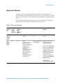
Upconverter Memory
The N8211A performance analog upconverter and N8212A performance vector
upconverter have several memory types, each used for storing a specific types of data.
Before removing sensitive data, it is important to understand how each memory type is
used.
The following tables describe each memory type used in the N8211A performance
analog upconverter and N8212A performance vector upconverter.
Table 1: Base Instrument Memory
Memory
Type and
Size
Writable
During
Normal
Operation?
Data
Retained
When
Powered
Off?
Purpose/Contents
Data Input Method
Location in Instrument and
Remarks
Main
Memory
(SDRAM)
64 MB
Yes
No
firmware operating
memory
operating system (not
user)
CPU board, not battery
backed
Main
Memory
(Flash)
20 MB
Yes
Yes
factory
calibration/configurati
on data user file
system, which includes
instrument status
backup, flatness
calibration, IQ
calibration, instrument
states, waveforms
(including header and
marker data),
modulation definitions,
and sweep lists
firmware upgrades and
user-saved data
CPU board (same chip as
firmware memory, but
managed separately)
Because this 32 MB memory
chip contains 20 MB of user
data (described here) and
12 MB of firmware memory,
a selective chip erase is
performed. User data areas
are selectively and
completely sanitized when
you perform the Erase and
Sanitize function.
SCPI Command:
:SYSTem:SECurity:SANitize
Agilent N8211A/N8212A Performance Upconverter Synthetic Instrument Module, 250 kHz to 20/40 GHz
7
1
Security Features
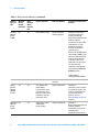
Table 1: Base Instrument Memory (continued)
Memory
Type and
Size
Writable
During
Normal
Operation?
Data
Retained
When
Powered
Off?
Purpose/Contents
Data Input Method
Location in Instrument and
Remarks
Firmware
Memory
(Flash)
12 MB
No
Yes
main firmware image
factory installed or
firmware upgrade
CPU board (same chip as
main flash memory, but
managed separately)
During normal operation, this
memory cannot be
overwritten except for LAN
configuration. It is only
overwritten during the
firmware installation or
upgrade process.
Because this 32 MB memory
chip contains 20 MB of user
data and 12 MB of firmware
memory (described here),
a selective chip erase is
performed. User data areas
are selectively and
completely sanitized when
you perform the Erase and
Sanitize function.
SCPI Command:
:SYSTem:SECurity:SANitize
Yes
Yes
LAN configuration
front panel entry or
remotely
Battery
Backed
Memory
(SRAM)
512 kB
Yes
Yes
user-editable data
(table editors)
last instrument state,
last instrument state
backup, and persistent
instrument state and
instrument status
firmware operations
CPU board
The battery can be removed
to sanitize the memory, but
must be reinstalled for the
instrument to operate.
(Refer to “Battery
Removal/Replacement" on
page 23.)
Boot ROM
Memory
(Flash)
128 kB
No
Yes
CPU bootup program
and firmware
loader/updater
factory programmed
CPU board
During normal operation, this
memory cannot be
overwritten or erased. This
read-only data is
programmed at the factory.
8
Agilent N8211A/N8212A Performance Upconverter Synthetic Instrument Module, 250 kHz to 20/40 GHz
Security Features
1
Table 1: Base Instrument Memory (continued)
Data
Retained
When
Powered
Off?
Purpose/Contents
Data Input Method
Location in Instrument and
Remarks
Calibration No
Backup
Memory
(Flash)
512 KB
Yes
factory
calibration/configurati
on data backup
no user data
factory or service only
motherboard
Boards
Memory
(Flash)
512 Bytes
No
Yes
factory calibration and
information files, code
images, and self-test
limits
no user data
factory or service only
All RF boards, baseband
generator, and motherboard
Microprocessor
Cache
(SRAM)
3 kB
Yes
No
CPU data and
instruction cache
memory is managed by
CPU, not user
CPU board, not battery
backed
Memory
Type and
Size
Writable
During
Normal
Operation?
Agilent N8211A/N8212A Performance Upconverter Synthetic Instrument Module, 250 kHz to 20/40 GHz
9
1
Security Features
Removing Sensitive Data from Memory
This section describes several security functions that can be used to remove sensitive
data stored in the N8211A performance analog upconverter and N8212A performance
vector upconverter when moving them from a secure development environment.
NOTE
All security functions described in this section have an equivalent SCPI command for
remote operation. For more information about the SCPI commands available for removing
sensitive data from memory, refer to “SCPI Commands" on page 15.
Declassification
To declassify the instrument in compliance with Department of Defense (DoD)
standards, perform the following steps:
1 Send the SCPI command SYSTem:SECurity:LEVel SANitize
2 Send the SCPI command SYSTem:SECurity:LEVel:STATe ON
3 Send the SCPI command SYSTem:SECurity:LEVel:STATe OFF
4 Remove the battery, leave it out of the instrument for one minute, and replace it.
Refer to “Battery Removal/Replacement" on page 23 for details.
10
Agilent N8211A/N8212A Performance Upconverter Synthetic Instrument Module, 250 kHz to 20/40 GHz
Security Features
1
Additional Procedures
The following procedures offer additional security details.
Erase All
This function removes all user files, user flatness calibrations, user I/Q calibrations, and
resets all table editors with original factory values, ensuring that user data and
configurations are not accessible or viewable. The instrument appears as if it is in its
original factory state, however, the memory is not sanitized. This action is relatively
quick, typically taking less than one minute (the exact time depends on the number of
files).
On the upconverter, send the following SCPI command:
:SYSTem:SECurity:ERASall
Agilent N8211A/N8212A Performance Upconverter Synthetic Instrument Module, 250 kHz to 20/40 GHz
11
1
Security Features
Erase and Overwrite All
This function performs the same actions as Erase All and then clears and overwrites the
various memory types in accordance with Department of Defense (DoD) standards as
described below.
SRAM
All addressable locations are overwritten with random characters.
CPU Flash
All addressable locations are overwritten with random characters and then the flash blocks are
erased. This accomplishes the same purpose of a chip erase, however, only the areas that are no
longer in use are erased and the factory calibration files are left intact. System files are restored after
erase.
Hard Disk
All addressable locations are overwritten with a single character. (This is insufficient for top secret
data, according to DoD standards. For top secret data, the hard drive must be removed and
destroyed.)
On the upconverter, send the following SCPI command:
:SYSTem:SECurity:OVERwrite
Erase and Sanitize All
This function performs the same actions as Erase and Overwrite All and then adds
more overwriting actions as described below.
SRAM
All addressable locations are overwritten with random characters.
CPU Flash
Overwrites all addressable locations with random characters and then erases the flash blocks. This
accomplishes the same purpose as a chip erase. System files are restored after erase.
Hard Disk
All addressable locations are overwritten with a single character and then a random character. (This
is insufficient for top secret data, according to DoD standards. For top secret data, the hard drive
must be removed and destroyed.)
After executing this function, you must manually remove the battery to sanitize the
instrument in compliance with Department of Defense (DoD) standards. Refer to
“Battery Removal/Replacement" on page 23 for details.
12
Agilent N8211A/N8212A Performance Upconverter Synthetic Instrument Module, 250 kHz to 20/40 GHz
Security Features
1
Removing Persistent State Information Not Removed During Erase
Persistent State
The persistent state settings contain instrument setup information that can be toggled
within predefined limits such as display intensity, contrast, and the LAN address. In
vector models, the user IQ Cal is also saved in this area.
The following SCPI commands can be used to clear the IQ cal file and to set the
operating states that are not affected by a synthetic upconverter power-on, preset, or
*RST command to their factory default:
Instrument Setup
On the upconverter send this command to the upconverter:
:SYSTem:PRESet:PERSistent
LAN Setup
The LAN setup (hostname, IP address, subnet mask, and default gateway) information is
not defaulted with a upconverter power-on or *RST command. This information can
only be changed or cleared by entering new data.
Agilent N8211A/N8212A Performance Upconverter Synthetic Instrument Module, 250 kHz to 20/40 GHz
13
1
Security Features
User IQ Cal File (Vector Models Only)
When a user-defined IQ calibration has been performed, the cal file data is removed by
setting the cal file to default, as follows:
Send these commands to the N8211A or N8212A upconverter:
CAL:IQ:DEF
CAL:WBIQ:DEF
If Your Instrument is Not Functioning
If the instrument is not functioning and you are unable to use the security functions, you
may physically remove the processor board and hard disk, if installed, from the
instrument. Once these assemblies are removed, proceed as follows:
For removal and replacement procedures, refer to the procedure at the end of this
document.
Processor Board
Either
• Discard the processor board and send the instrument to a repair facility. A new
processor board will be installed and the instrument will be repaired and calibrated. If
the instrument is still under warranty, you will not be charged for the new processor
board.
or
• If you have another working instrument, install the processor board into that
instrument and erase the memory. Then reinstall the processor board back into the
non-working instrument and send it to a repair facility for repair and calibration. If
you discover that the processor board does not function in the working instrument,
discard the processor board and note that it caused the instrument failure on the repair
order. If the instrument is still under warranty, you will not be charged for the new
processor board.
14
Agilent N8211A/N8212A Performance Upconverter Synthetic Instrument Module, 250 kHz to 20/40 GHz
Security Features
1
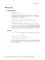
SCPI Commands
Security Commands
:SECurity:ERASeall
:SYSTem:SECurity:ERASall
This command removes all user files, table editor files, flatness correction files, and
baseband generator files. This command differs from the :DELete:ALL command,
which does not remove table editor files.
:SECurity:LEVel NONE|ERASe|OVERwrite|SANitize
:SYSTem:SECurity:LEVel NONE|ERASe|OVERwrite|SANitize
:SYSTem:SECurity:LEVel?
This command selects the secure mode and enables you to select a level of security.
:SECurity:LEVel:STATe must be set to ON to activate the selected security level,
and power must be cycled to perform the selected cleaning operation. Selecting NONE
will preset the upconverter to the factory state. For other cleaning operation descriptions,
see SECurity:ERASall, SECurity:OVERwrite, and SECurity:SANitize.
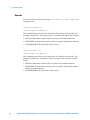
Remarks
:SECurity:LEVel:STATe must be set to ON to activate the selected security level.
:SECurity:LEVel:STATe ON|OFF|1|0
:SYSTem:SECurity:LEVel:STATe ON|OFF|1|0
:SYSTem:SECurity:LEVel:STATe?
When this command is enabled (1) it activates the selected security level. When disabled
(0) it executes the selected security level. Once the secure mode is entered, the security
level can only be increased.
Agilent N8211A/N8212A Performance Upconverter Synthetic Instrument Module, 250 kHz to 20/40 GHz
15
1
Security Features
Remarks
You can exit the secure mode by entering :SYST:SECUrity:LEVel NONE, or by
cycling the power.
:SECurity:OVERwrite
:SYSTem:SECurity:OVERwrite
This command removes all user files, table editor files, flatness correction files, and
baseband generator files. The memory is then overwritten with random data as follows:
• SRAM All addressable locations will be overwritten with random characters.
• HARD DISK All addressable locations will be overwritten with random characters.
• FLASH MEMORY The flash blocks will be erased.
:SECurity:SANitize
:SYSTem:SECurity:SANitize
This command removes all user files, table editor files, flatness correction files, and
baseband generator files. The memory is then overwritten with a sequence of data as
follows:
• SRAM All addressable locations will be overwritten with random characters.
• HARD DISK All addressable locations will be overwritten with a single character
and then a random character.
• FLASH MEMORY The flash blocks will be erased.
16
Agilent N8211A/N8212A Performance Upconverter Synthetic Instrument Module, 250 kHz to 20/40 GHz
Security Features
1
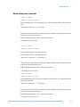
Memory Subsystem Commands
:CATalog:BINary
:MEMory:CATalog:BINary?
This command outputs a list of the binary files. The return data will be in the following
form:
<mem used>,<mem free>{,"<file listing>"}
The upconverter will return the two memory usage parameters and as many file listings
as there are files in the directory list.
Each file listing parameter will be in the following form:
"<file name,file type,file size>"
:CATalog:STATe
:MEMory:CATalog:STATe?
This command outputs a list of the state files.
The return data will be in the following form:
<mem used>,<mem free>{,"<file listing>"}
The upconverter will return the two memory usage parameters and as many file listings
as there are files in the directory list.
Each file listing parameter will be in the following form:
"<file name,file type,file size>"
:CATalog:UFLT
:MEMory:CATalog:UFLT?
This command outputs a list of the user-flatness correction files. The return data will be
in the following form:
<mem used>,<mem free>{,"<file listing>"}
The upconverter will return the two memory usage parameters and as many file listings
as there are files in the directory list.
Each file listing parameter will be in the following form:
"<file name,file type,file size>"
Agilent N8211A/N8212A Performance Upconverter Synthetic Instrument Module, 250 kHz to 20/40 GHz
17
1
Security Features
:CATalog[:ALL]
:MEMory:CATalog[:ALL]?
This command outputs a list of all files in the memory subsystem, but does not include
files stored on the Option 002/602 baseband generator.
The return data is in the following form:
<mem used>,<mem free>{,"<file listing>"}
The upconverter returns the two memory usage parameters and as many file listings as
there are files in the memory subsystem.
Each file listing parameter is in the following form:
"<file name,file type,file size>"
18
Agilent N8211A/N8212A Performance Upconverter Synthetic Instrument Module, 250 kHz to 20/40 GHz
2
Safety and Regulatory
“General Safety Considerations" on page 20
“Lithium Battery Disposal" on page 21
“Assistance" on page 21
“Certification" on page 21
The following safety notes are used throughout this manual. Familiarize yourself with
each of the notes and its meaning before operating this instrument.
CAUTION
Caution denotes a hazard. It calls attention to a procedure that, if not correctly
performed or adhered to, would result in damage to or destruction of the product.
Do not proceed beyond a caution sign until the indicated conditions are fully
understood and met.
WA R N I N G
Warning denotes a hazard. It calls attention to a procedure which, if not correctly
performed or adhered to, could result in injury or loss of life. Do not proceed
beyond a warning note until the indicated conditions are fully understood and
met.
Agilent Technologies
2
Safety and Regulatory
General Safety Considerations
The following safety notes apply specifically to upconverters. These notes also appear in
other chapters of this service guide as required.
20
WA R N I N G
These servicing instructions are for use by qualified personal only. To avoid
electrical shock, do not perform any servicing unless you are qualified to do so.
WA R N I N G
The opening of covers or removal of parts is likely to expose dangerous voltages.
Disconnect the product from all voltage sources before starting to open.
WA R N I N G
The detachable power cord is the instrument disconnecting device. It
disconnects the mains circuits from the mains supply before other parts of the
instrument. The front panel switch is only a standby switch and is not a LINE
switch (disconnecting device).
WA R N I N G
The power cord is connected to internal capacitors that may remain live for 5
seconds after disconnecting the plug from its power supply.
WA R N I N G
This is a Safety Class 1 Product (provided with a protective earthing ground
incorporated in the power cord). The mains plug shall only be inserted in a socket
outlet provided with a protective earth contact. Any interruption of the protective
conductor inside or outside of the product is likely to make the product
dangerous. Intentional interruption is prohibited.
WA R N I N G
Replace battery only with the same or equivalent type recommended. Discard
used batteries according to manufacturer’s instructions.
WA R N I N G
If this product is not used as specified, the protection provided by the equipment
could be impaired. This product must be used in a normal condition (in which all
means for protection are intact) only.
CAUTION
Many of the assemblies in this instrument are very susceptible to damage from
electrostatic discharge (ESD). Perform service procedures only at a static-safe
workstation and wear a grounding strap.
Agilent N8211A/N8212A Performance Upconverter Synthetic Instrument Module,
2
Safety and Regulatory
Lithium Battery Disposal
When the battery on the A18 CPU is exhausted and/or ready for disposal, dispose of it
according to your country’s requirements. You can return the battery to your nearest
Agilent Technologies Sales and Service office for disposal, if required.
Assistance
Product maintenance agreements and other customer assistance agreements are available
for Agilent Technologies products. For any assistance, contact your nearest Agilent
Technologies sales and service office.
Certification
Agilent Technologies Company certifies that this product met its published
specifications at the time of shipment from the factory. Agilent Technologies further
certifies that its calibration measurements are traceable to the United States National
Institute of Standards and Technology, to the extent allowed by the Institute’s calibration
facility, and to the calibration facilities of other International Standards Organization
members.
Agilent N8211A/N8212A Performance Upconverter Synthetic Instrument Module, 250 kHz to 20/40 GHz
21
2
22
Safety and Regulatory
Agilent N8211A/N8212A Performance Upconverter Synthetic Instrument Module,
Security Features Guide
3
Battery Removal/Replacement
“Step 1. Outer Instrument Cover Removel/Replacement" on page 24
“Step 1. Outer Instrument Cover Removel/Replacement" on page 24
“Step 2. Inner Instrument Top and Bottom Cover
Removel/Replacement" on page 26
“Step 3. A18 CPU Removal/Replacement" on page 28
“Step 4. A18BT1 Battery Removal/Replacement" on page 29
CAUTION
Opening the instrument cover and removing any assemblies other than the A18 CPU
may invalidate your instrument calibration and your upconverter may have to be
returned to Agilent to be re-calibrated!
Agilent Technologies
23
3
Battery Removal/Replacement
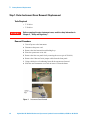
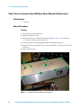
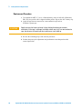
Step 1. Outer Instrument Cover Removel/Replacement
Tools Required
• T-15 driver
• T-20 driver
WA R N I N G
Before removing the outer instrument cover, read the safety information in
Chapter 2, “Safety and Regulatory”.
Removal Procedure
1 Turn off power to the instrument.
2 Disconnect the power cord.
3 Remove the four bottom feet and locking keys.
4 Place the upconverter on its side.
5 Remove the four rear panel feet by removing the screws (p/n 0515-0619).
6 Remove the Coherent Carrier jumper cables from the front panel.
7 Using a thick piece of cushioning foam, tilt the upconverter forward.
8 Slide the outer instrument cover back to remove it from the frame.
Figure 1
24
Instrument Cover Removal
Agilent N8211A/N8212A Performance Upconverter Synthetic Instrument Module, 250 kHz to 20/40 GHz
Battery Removal/Replacement
3
Replacement Procedure
CAUTION
When sliding the instrument cover on, make sure that you do not catch the edge of
the RF shield on the rear panel, also make sure that the grey cable is not sticking out
of the inner top cover slot.
• Reverse the order of the removal procedures.
• Torque all T-15 screws to 21-inch pounds.
• Torque all T-20 screws to 21-inch pounds.
Agilent N8211A/N8212A Performance Upconverter Synthetic Instrument Module, 250 kHz to 20/40 GHz
25
3
Battery Removal/Replacement
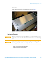
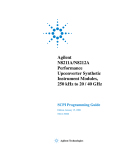
Step 2. Inner Instrument Top and Bottom Cover Removel/Replacement
Tools Required
• T-10 driver
Removal Procedure
Top Cover
1 Turn off power to the instrument.
2 Disconnect the power cord.
3 Remove the outer cover from the upconverter. Refer to “Step 1. Outer Instrument
Cover Removel/Replacement" on page 24.
4 Place the upconverter flat and upright with the front panel facing you.
5 Remove four screws (p/n 0515-1521) on the sides, and five screws (p/n 0515-0430)
on the top.
6 Remove the top cover.
Figure 2
26
Instrument Inner Top Cover Screw Location
Agilent N8211A/N8212A Performance Upconverter Synthetic Instrument Module, 250 kHz to 20/40 GHz
Battery Removal/Replacement
3
Bottom Cover
Remove four screws (p/n 0515-1521) and remove the cover. See Figure 3.
Figure 3
Instrument Inner Bottom Cover Screw Location
Replacement Procedure
CAUTION
Make sure that the brown orange cable (W13) sits in the relief slot of the top cover,
but does not sit above the surface. The relief slot is located under the cable routing
label.
CAUTION
Position the internal top cover on the instrument making sure that the grey flex
cable sits properly in the slot. See arrow in Figure 2.
• Reverse the order of the removal procedures.
• Torque all T-10 screws to 9-inch pounds.
Agilent N8211A/N8212A Performance Upconverter Synthetic Instrument Module, 250 kHz to 20/40 GHz
27
3
Battery Removal/Replacement
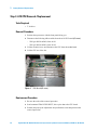
Step 3. A18 CPU Removal/Replacement
Tools Required
• T-10 driver
Removal Procedure
1 Position the upconverter with the front panel facing you.
2 Disconnect the following ribbon cables from the A18 CPU board (#5 arrow):
• W29 (p/n N8210-60202) from A18 J1
• W30 (p/n N8210-60203) from A18 J2
3 Lift the retention levers and disconnect the CPU from the motherboard.
4 Lift the CPU out of the slot.
Figure 4
CPU Board (#5 arrow)
Replacement Procedure
1 Reverse the order of the removal procedure.
2 Send command "DIAG:FILE:REST", this copies data to the CPU board.
3 Perform the post-repair adjustments and performance tests that pertain to this
removal procedure.
28
Agilent N8211A/N8212A Performance Upconverter Synthetic Instrument Module, 250 kHz to 20/40 GHz
Battery Removal/Replacement
3
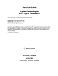
Step 4. A18BT1 Battery Removal/Replacement
WA R N I N G
This battery contains lithium. Do not incinerate or puncture this battery. Do not
install this battery backwards. Dispose of the battery in a safe manner and in
accordance with your country's requirements. You can return batteries to your
nearest Agilent Technologies Sales and Service office for disposal, if required.
Refer to “Lithium Battery Disposal" on page 21.
Tools Required
• T-10 driver (N8212A only)
• flat-head screw driver
Removal Procedure
1 Lay the A18 CPU board on a static safe work surface.
2 Remove the tape holding down the battery. Save this tape to reapply over the new
battery.
3 Using the flat-head screw driver, remove the A18BT1 by leveraging the battery out of
the battery’s socket.
A18BT1
Figure 5
A18BT1 Battery
Agilent N8211A/N8212A Performance Upconverter Synthetic Instrument Module, 250 kHz to 20/40 GHz
29
3
Battery Removal/Replacement
Replacement Procedure
1 To install the A18BT1 3 V, 0.16 A Lithium battery with p/n 1420-0314 (Panasonic
BR 2325), the positive side is aligned with the positive sign on the A18’s battery clip.
2 Apply the tape that was removed or a non-conductive tape such as
Permacel Capcom tape.
CAUTION
Apply tape over the battery to keep it from shaking free during instrument
movement. If the tape is no longer available or does not stick, use non-conductive
tape, but do not use Scotch tape that could cause static build up.
3 Reverse the remaining steps of the removal procedure.
4 Perform the post-repair adjustments and performance tests that pertain to this
removal procedure.
30
Agilent N8211A/N8212A Performance Upconverter Synthetic Instrument Module, 250 kHz to 20/40 GHz