1
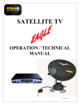
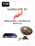
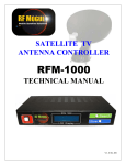
EAGLE RE-1
CONTROLLER
For Use On
MotoSAT HD Mounts
Supported Systems
HD SL5 DirecTV
HD DP3 Dish Network
HD SC2 SHAW
HD DP3 BELL TV
EXECUTIVE
DirecTV 101
Dish Network 119
MSC-60 SHAW
MD-500 Dish Network
MD-1000 Dish Network
Made in USA
24 April 2014
1
Index
Disclaimer
...........................................
3
Parts Bill of Materials .................................
4
Requirements for Installation .....................
5
What you wish you had ..............................
6
Installation .................................................
7
Wiring Diagrams .......................................
8
Menus and Operation .................................
10
Updating and Maintaining Software ..........
11
How to Measure Focal Points .....................
12
Assistance....................................................
17
2
Disclaimer
•
•
•
•
•
•
•
•
•
•
•
•
•
•
The RF Mogul EAGLE RE-1 is designed to operate all MotoSAT mounts
with the exception of the round 24" single LNB reflector.
It will operate the DirecTV, Dish Network, SHAW and Bell TV HD
systems.
The MotoSAT mount must be mechanically sound with functional motors
and count sensors.
The antenna must not be bent "tweaked" or damaged in anyway.
The mount should not have excessive slop or play (wobble) as this will
directly affect the ability of the RF Mogul Eagle controller to peak the
signal for best performance.
The LNB must be 100% functional. If a Shaw system is being used you
must have a 75E LNB for the 70cm dish and a 60E LNB for the 60cm dish.
We strongly recommend replacement of the current SHAW LNB to the new
xKu version. Changing of the receiver's channel map will have to be done
if you change from a dual LNB to a triple xKu LNB.
If your focal point on your MotoSAT mount is not within plus or minus 1/4"
to the specifications in this document then correct that issue before trying to
operate the system.
Check all coax connections and cable for moisture intrusion and wear.
Replace connectors and cable where necessary.
Mount must not have excessive movement in Azimuth, Elevation or Skew
Antenna must not be bent or "tweaked".
The focal point of the LNB on the MotoSAT mount bust be +/- 1/4" to the
specification include in this document.
When making connections to the 12 pin controller connector make sure they
are clean, properly installed according to the wiring diagram included in this
manual.
Check that the proper software for your configuration has been loaded into
your controller before pressing SEARCH. If not, load the proper software
and then proceed.
If your MotoSAT mount cannot perform to its peak capacity due to
hardware issues then EAGLE RE-1 controller will not be able to correct that
issue.
Most installation problems are related to
configuration or connectivity.
3
Bill of Materials
1.
2.
3.
4.
5.
1 ea.
1 ea.
1 ea.
1 ea.
1 ea.
12 Pin Connector
GPS w/12 feet of cable
RF Mogul EAGLE RE-1 Controller
Blue Light adapter
12 VDC Power Supply
1
2
4
5
3
4
STOP !!!
YOU MUST CHECK AND CORRECT THE FOCAL POINT OF YOUR
DISH BEFORE DOING BEGINNING YOUR INSTALL. FAILURE TO DO
SO WILL CREATE PROBLEMS IN ACQUISITION!!!
(See page 13 for details)
Requirements for Installation
•
Color Blind? Ask a friend or neighbor for assistance. Meet a new friend.
•
Patience and attention to details will make this go smoothly. Do not rush
through this document. Analyze each step and consider the implications of
skipping or ignoring any of the steps or recommendations. The correct LNB
must be installed for the software used. Failure to do so will result in the
system not performing an automatic acquisition.
o Shaw 60cm dish must use a 60E LNB
o Shaw 70cm or 75cm HD dish must use a 75E LNB
•
GPS must be mounted where it can best receive the signal from the GPS
satellites.
•
All entry holes in the roof must be sealed properly to prevent water damage
from leaks.
•
Do not splice the GPS cable. If longer lengths are required please request
them from the factory.
•
If the roof is fiberglass or rubber coated (not metal) then the GPS may be
installed inside the RV. It must be unobstructed wherever it is installed.
•
Do not stack electronic components because of potential heat problems.
Most receivers produce a lot of heat even when turned OFF. HEAT is a
primary cause of system failure to perform properly. Do not stack the
controller on top of the receiver.
5
What you wish you had
Pre-installation recommendations for the RF Mogul Eagle Controller to a
MotoSAT mount...
1.
2.
3.
4.
5.
6.
7.
The ability to receive Email and download files from an Email.
Know how to put files on a USB Flash Drive from your computer.
Read and follow wiring instructions.
Cannot be color blind.
A basic Volt/Ohm Meter.
One small screw driver for use on the 12 position control cable connector.
Flashlight
Recommended Tools for the RF Mogul Eagle to MotoSAT Upgrade
1.
2.
3.
4.
5.
6.
#2 Phillips screwdriver
7/16 Open End Wrench
Pliers
Knife
Volt Ohm Meter
Inside assistant
Other possible item needed for install
1.
2.
3.
4.
5.
SWM DirecTV 21 Volt Power Inserter for SWM applications
Drill for roof GPS installation
100% Silicone or Dicor roof sealant
Threaded Reed switches
3M Scotchloks (UR2 IDC Home Depot) for wire splicing
6
INSTALLATION
If your system is equipped with
a GPS, it is required that you bypass
your existing GPS and splitter on the
roof. A simple barrel connector will
allow you to bypass the MotoSAT GPS
and splitter. The coax cable inside the
mount must go directly to the LNB from
the controller.
The GPS/Splitter is located in
two possible locations....
1. On the roof near the GPS or
2. Under the cover located in front
of the mount as shown.
Use a threaded coax barrel connector to
bypass the GPS/Splitter if required.
Note: The GPS may work inside of a RV if
the RV has a non-metal roof. Try it inside
first.
EAGLE RE-1 Controller
Or install the GPS on the roof
of the RV near the cable
entrance in the roof.
12 Volt power
7
Control cable
w/GPS
To Rec
To Mount
Wiring Diagram
For the Control Cable 12 Pin Connector
Wiring Color Code
Pin
Color
MotoSAT
1.
2.
3.
4.
5.
6.
7.
8.
9.
10.
11.
Black
Brown
Red
Orange
Not Used
Not Used
Yellow
Blue
Purple
Green
12.
Color
RF Mogul
How Used
Black
Red /Blue Light Adapter
White
Motor, Azimuth
Motor, Azimuth/Skew
Motor, Elevation/Skew
Motor, Elevation
Not Used
Not Used
Sensor Count, Azimuth
Sensor Count, Elevation
Sensor Count, Skew
Ground
Power, Blue light Connection
GPS TXD
1. The GPS cable has a YELLOW wire in the bundle.
It is not used so cut it OFF.
2. Carefully cut and remove all stranded shield
3. Inspect for small wire strand shorting across pins.
Note: Pins 10 and 11 have a dual function
Pin 10 - Green (MotoSAT Cable) Black is used as Ground.
Pin 11 - Red (for GPS) Blue Light Adapter (for Blue LED) is used as voltage
to the GPS and Blue Light.
Note: White from the existing MotoSAT control cable spliced to the "Blue Light
Adapter" will maintain the blue light on your reflector at night. CAUTION---do
not attach the white wire directly to pin #11 without the blue light adapter.
Damage to the blue light will occur.
8
Note: If you do not wire this
connector properly damage to
your mount could be a result.
Double check all connections
before applying power.
Connecting the Blue Light Adaptor
Connection of Blue Light
Adaptor using a snap type
connector.
For splicing, cut
wire blunt before
inserting into the
Scotch Lock
connector.
9
Menus and Operation
Your controller is menu driven. By selecting a particular menu you can perform
many functions besides just "SEARCHING for satellite".
TO SEARCH
•
Press Power button
o Displayed will be the....
System configuration (software configuration)
HD Mounts
•
•
•
•
•
•
ms HD 1 = Shaw Triple Satellite xKu LNB
ms HD 2 = DirecTV SWM 3 LNB Option
ms HD 3 = Dish Network Triple Satellite 1000.2 LNB
ms HD 4 = Bell TV Triple Satellite 1000.2 LNB
ms HD 5 = DirecTV Slim Line 5 LNB
ms HD 6 = Shaw Dual satellite LNB (Legacy)
18 " Mounts
•
ms 18 7 = DirecTV Single Satellite
•
ms 18 8 = Dish Network Single Satellite
•
ms 18" 9 = Bell TV Single Satellite
Version of software i.e. 14.02.07
Options
• SEARCH (up arrow)
• STOW (down arrow)
• MENU (press "SELECT" which is the POWER button again
to enter menu)
TO ENTER MENU
•
Press the Power button again after turning ON the power to enter the
"menu" portion of your system.......
o Displayed will be the Up and Down arrows which will help you
navigate through the menu. Once the portion of the menu that
you want is displayed, press SELECT (power button) to "select"
that option....
•
•
•
•
1: shutdown - will turn OFF your controller
2: search - will direct the mount to search for your specific
satellite that is specified in your system configuration
3: stow - will cause the mount to return to its travel position
4: move azimuth - pressing and holding the appropriate
button will manually move your mount in azimuth (Up arrow
CLOCKWISE, Down arrow COUNTERCLOCKWISE
10
•
•
•
•
•
•
•
•
5: move elevation - pressing and holding the appropriate
button will manually move your mount in elevation (Up
arrow UP, Down arrow DOWN
6: move skew - pressing and holding the appropriate button
will manually move your dish in skew (Up arrow right side
DOWN, Down arrow left side DOWN
7: test dish - will move the dish in all axis for one complete
cycle
8: temperature - will display current operating temperature
of its operating environment.
9: test azimuth - will automatically do a test of the azimuth
sensor
10: test elevation - will automatically do a test of the
elevation sensor
11: test skew - will automatically do a test of the skew sensor
12: exit - Selecting this option will take you back to main
menu
NOTE: There is an "OVER TEMPERATURE" condition that will be displayed at
the beginning of the SEARCH function if the operating environment is in excess of
136°F. It will not prevent the SEARCH routine but will warn of potential
damaging heat conditions for the equipment within that operating environment.
Updating and Maintaining Software
•
•
•
•
•
The software can be maintained by use of a USB Flash Drive.
Go to www.rfmogul.com and download the software that best fits your
application. Make sure that it is placed in the "root directory".
Insert your flash drive into your EAGLE RE-1 controller.
Turn power ON
Wait for the message to be displayed that will indicate that the software has
been successfully loaded (usually 8 seconds).
Remove the flash drive and press SEARCH to implement acquisition.
11
Most "low signal" can be attributed to
improper focal point. The following will
assist you in determining if you have
problems with your reflector or LNB arm.
HOW TO MEASURE FOCAL POINT
HD SERIES MOUNTS
12
INTRODUCTION AND HOW TO MEASURE
It is important to remember that the focal point of any HD Series mount will always be
measured from a specific point. Follow these simple rules and you will be able to determine the
focal point of your dish. All of these measurements will be plus/minus ¼ inch.
Step
#1
Step
#2
Place the leading edge of your measuring tape over
the lip of your dish in this manner.
Place the trailing edge of your measuring tape to the
point specified by your LNB type.
13
DIRECTV SL5
(Circular Polarized 99 Ka, 101 Ku, 103Ka, 110 Ku, 119 Ku)
STRAIGHT LNB
26 ”
Measure to front edge of the LNB Cover.
CURVED LNB
26 “
Measure to front edge of the LNB Cover.
14
DISH NETWORK DP3
(Circular Polarized 110 Ku, 119 Ku, and 129 Ku)
BELL TV
(Circular Polarized 82 Ku and 91 Ku)
26 3/8 “
Measure to the front edge of the LNB cover.
15
SHAW DIRECT
(Linear Polarized 107.3 Ku and 111.1 Ku)
For HD-SC2 Mounts
24 ⅜”
For MSC60 Mounts
21 ½”
Measure to the point just behind the white LNB cover.
16
ASSISTANCE
For questions or assistance concerning this product please contact your installing
dealer.
For additional assistance you may contact [email protected].
This product was manufactured
in the
United States of America.
RF Mogul
3604 South Via Terra
Salt Lake City, UT 84115
801-895-3392
[email protected]
[email protected]
17